US7495537B2 - Method and apparatus for dynamic magnetic field control using multiple magnets - Google Patents
Method and apparatus for dynamic magnetic field control using multiple magnetsDownload PDFInfo
- Publication number
- US7495537B2 US7495537B2US11/502,335US50233506AUS7495537B2US 7495537 B2US7495537 B2US 7495537B2US 50233506 AUS50233506 AUS 50233506AUS 7495537 B2US7495537 B2US 7495537B2
- Authority
- US
- United States
- Prior art keywords
- magnet
- magnetic field
- field
- magnets
- operating point
- Prior art date
- Legal status (The legal status is an assumption and is not a legal conclusion. Google has not performed a legal analysis and makes no representation as to the accuracy of the status listed.)
- Active, expires
Links
Images


Classifications
- A—HUMAN NECESSITIES
- A61—MEDICAL OR VETERINARY SCIENCE; HYGIENE
- A61B—DIAGNOSIS; SURGERY; IDENTIFICATION
- A61B5/00—Measuring for diagnostic purposes; Identification of persons
- A61B5/06—Devices, other than using radiation, for detecting or locating foreign bodies ; Determining position of diagnostic devices within or on the body of the patient
- A61B5/061—Determining position of a probe within the body employing means separate from the probe, e.g. sensing internal probe position employing impedance electrodes on the surface of the body
- A61B5/062—Determining position of a probe within the body employing means separate from the probe, e.g. sensing internal probe position employing impedance electrodes on the surface of the body using magnetic field
Definitions
- This inventionrelates to the dynamic control of a magnetic field generated by two or more articulated magnets.
- One of the embodiments of the methods disclosedapplies to operator-directed control of the magnetic field direction and magnitude generated by two articulated magnets in an operating region.
- the magnets consideredare permanent magnets generally facing one another and the operating region is centered in between the two magnets.
- the operator-directed controlis executed by means of electromechanical positioners that move the two magnets appropriately.
- the six degrees of freedom(three for each magnet) allow each magnet to translate along the line between the two magnet centers, and each magnet to rotate in two angles ⁇ and ⁇ along respective axes.
- Other similar embodimentsthat could be used to control a multiplicity of magnets to generate a specific magnetic field (direction and magnitude) at a specific point in space are also included in the present invention.
- the procedure to execute a proper turn in a preferred embodiment of the present inventionentails setting a series of steps for the turn, i.e. finding intermediate field vectors (directions and magnitudes) which couple the two known (initial and target) field vectors at the operating point through the turn.
- the problem of finding the articulations or values of the parameters describing each of the degrees of freedom for the magnets necessary to generate the given fieldis the inverse problem of finding the field position, direction, and magnitude of magnets having specific articulations.
- the inverse problem referred to aboveis solved in three steps.
- the magnitude of the desired field at the operating pointis apportioned to the two contributing fields of the two articulated magnets.
- an approximate representation for each magnetic field generated by each magnetis used to ensure quick convergence of the algorithm to an approximate solution.
- optimization methodsare applied to a more accurate and mathematically complex field representation to obtain a refined estimate of the magnets control parameters and a more accurate field solution.
- the magnetic field apportionment algorithmoperates under various constraints related to the nature of magnet design and field distributions to optimize field uniformity near the operating point.
- a nested polynomial representation for each of the magnet fieldsenables an efficient solution to the inverse problem. These representations are based on calibration data acquired prior to any navigation procedure. Optimization operates separately for each magnet in consideration of the apportioned fields.
- the inverse problemis formulated as a simultaneous optimization in all degrees of freedom, and the approximate polynomial field representation of step two is replaced by a more accurate field representation.
- One embodiment of the present inventionuses a spherical harmonics expansion field representation.
- the control algorithmproceeds in three steps.
- the target fieldis apportioned between the N magnets.
- the inverse problem of finding the magnets articulations that provide the apportioned field at the operating pointis solved independently for each of the N magnets using a first level of magnetic field representation.
- the problem of finding the magnet articulations that generate the target field at the operating pointis formulated as a simultaneous constrained optimization problem for all N magnets.
- the third stepuses the output of step two as a starting point in the neighborhood of the optimal solution and also uses a more accurate, second level of magnetic field representation for optimization.
- the magnetspreferably comprise one or more three types: permanent, permanent focusing, or electromagnetic, and are preferably permanent magnets.
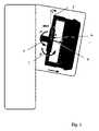
- FIG. 1is a schematic representation of one of the magnets and associated motion axes, including rotation angle ⁇ and pivoting angle ⁇ .
- FIG. 3shows the parameterization ( ⁇ , ⁇ , ⁇ ) for the orientation and magnitude of the projection of the magnetic field B onto a given (X M , Z M ) plane.
- FIG. 4shows maximum Z values achievable as a function of the pivoting angle ⁇ . This represents the spatial constraint imposed by the fixed magnet covers.
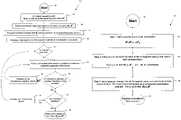
- FIG. 5presents the navigation algorithm flowchart.
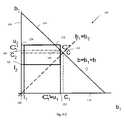
- FIG. 6illustrates the magnetic field vector progression from its initial state B 0 to its target state B T at the operating point through a succession of intermediate field values.
- FIG. 7shows the time progression of one of the state vector elements, Z, through a series of intermediate discrete values.
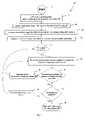
- FIG. 8presents the three-step inversion algorithm flowchart.
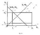
- FIG. 9-Apresents the case when the two magnitudes can be set equal;
- FIG. 9-B and FIG. 9-Cillustrate alternative magnitude apportionment choices when selecting equal magnitudes for the two fields does not lead to a satisfactory solution due to minimum and maximum magnitude constraints on each of the fields.
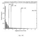
- FIGS. 11-A and 11 -Bpresent respectively corresponding angle and magnitude error distributions achieved by the optimized inverse algorithm of step 3 , using a local spherical harmonics function expansion and simultaneous optimization in all variables.
- control of two permanent magnetsenables dynamic generation of a specific magnetic field at an operating point.
- three Cartesian coordinates systemsare defined: one associated with each of the two magnets, and a third associated with the subject (world coordinate system).
- a given vectorsuch as that representing the desired magnetic field at the operating point within the subject, can be represented in each of these coordinate systems through the usual coordinate transformations.
- the generation of a dynamic magnetic field at the operating pointentails motion of the two magnets with respect to each other and also with respect to the subject.
- the position of the operating point in each magnet coordinate systemwill change, as well as the direction of the desired and intermediate field vectors. Accordingly, a series of intermediate magnetic field vectors that lie in a plane in the subject coordinate system will not in general lie in a plane of either of the magnet coordinate systems.
- the location and orientation of the two magnets at a given timeis called the state of the system at that time. The system state evolves in time as necessary to carry out a proper turn.
- FIG. 1The Cartesian referential frame (X M , Y M , Z M ) associated with each magnet is described in FIG. 1 .
- FIG. 2illustrates the field distribution in the central (X M , Z M ) magnet plane. By design this is a plane of even field symmetry with respect to Y M . Proceeding in the Y M direction, succeeding (X M , Z M ) planes have similar but gradually changing field patterns.
- Part AField representation
- Part Bfurther formulates the problem of magnetic navigation as that of fitting intermediate field vectors that define a proper turn while meeting a number of design constraints.
- Part Cfor each of the intermediate magnetic field vectors, the inverse problem of finding the magnet articulations that generate such a magnetic field at the operating point is solved in three steps.
- the first stepapportions the total magnetic field magnitude to each of the magnets.
- Step twofinds an approximate solution by solving the inverse problem for each of the magnets independently, given the first level of magnetic field representation introduced above and the apportioned fields of step one.
- Step threefinds an improved solution by simultaneously solving the problem for all magnets and using a more accurate field representation.
- the magnet designis meant to generate a specific magnetic field in a three dimensional volume.
- the generated fieldscan be represented to any level of accuracy by a finite element model or by three dimensional look-up tables. Such representations are inefficient in that they require storage of a large amount of data (in function of the desired accuracy) and lead to the use of computationally intensive three-dimensional interpolation methods.
- the magnetic fields requirementsare specific to magnetic navigation of catheters and guide wires in the body of a subject.
- the actual fields generated by magnets designed per the corresponding specificationscan be approximated to a very good accuracy by a basis expansion on spherical harmonic functions using a finite number of terms. In this representation, and referring to FIG.
- the even and odd symmetries of specific field components with respect to the magnet's Y M and Z M axes 2 and 4are taken into account.
- the expansion coefficientsare determined through a calibration procedure using the field values on an imaginary sphere containing the magnet.
- such a representationcan satisfy the Laplace equation that applies to stationary magnetic fields, and can also be used to locally represent the field in a specific volume (such as within a sphere enclosing the operating point) to a very high degree of accuracy.
- spherical harmonics functionsmay not be the most efficient means to represent the field distribution within a given accuracy and a limited number of coefficients. Further, such a representation might not be optimal in terms of performing the inverse calculations that are necessary to determine the system state that will generate a specific field at the operating point.
- these two limitationsare addressed by defining two levels of field representation.
- the first level of accuracyuses nested polynomials to provide a simplified field representation that allows efficient inversion algorithm convergence for each magnet independently to a state vector in the neighborhood of the optimum.
- the coefficients of the spherical harmonics expansionare calculated by performing a least squares minimization between the representation and the actual field in a specified volume of interest.
- the volume of interestcan be defined by a sphere that will encompass the operating point under all practical magnetic navigation situations.
- Such a local representationallows both a minimized error within the volume of interest for a given number of expansion terms as well as improved convergence of the inversion algorithm.
- the Y M component of the magnetic fieldis small (nominally zero by design). Because the field direction and magnitude vary slowly with distance e from the central plane, and because in a typical navigation configuration the Y M field components of the two facing magnets tend to combine destructively (the respective Y M axes being coaxial but in opposite directions), in a first approximation it is natural ignore the Y M field components. Any actual state vector optimization result obtained under this assumption for a target field within the navigation volume will include a small Y M field resultant. Under this assumption, the field for each magnet at any point within a volume of interest can then be represented by its orientation in the associated (X M , Y M ) plane and magnitude.
- uses nested polynomials as described below.
- each of the 15 coefficients a 0 , . . . ,a 4 ,b 0 , . . . ,b 4 ,c 0 , . . . ,c 4may in turn be represented by a fourth-degree polynomial function of Y M .
- the resulting set of 75 coefficientsaccurately describes the field magnitude at any point in a volume that encompasses the navigation sphere.
- the field angle ⁇ M 14can be represented by a function of
- the control algorithmconsiders an operating point located on the Z M axis.
- the projection of B T onto (X M , Z M )forms an angle ⁇ T , 0 ⁇ T ⁇ , with respect to the ⁇ X M axis.
- , ⁇ T )⁇ T ⁇ T .
- ⁇ (0) ⁇ 0 and ⁇grows monotonically from ⁇ ( ⁇ /2) ⁇ to ⁇ ( ⁇ /2) ⁇ and therefore the function ⁇ ( ⁇ ) is monotonic and one-to-one over the interval [ ⁇ /2, ⁇ /2] and such an angle can always be found.
- the coefficients d and ecan be modeled as quadratic functions of the field magnitude: d (
- )d 0 +d 1
- )e 0 +e 1
- Each coefficient d 0 , d 1 , d 2 , e 0 , e 1 , e 2is then modeled as a cubic function of Y M . Accordingly these 24 coefficients provide an accurate representation of the angle ⁇ ( ⁇ ).
- the navigation algorithmsolves the problem of finding a time sequence of source magnets states such that the final sequence state provides an accurate and precise estimate of the target magnetic field at the operating point.
- the problemcan be more formally stated as:
- a number of other conditionsare imposed to make the motions and articulations more efficient and safe; as examples, it is desirable to limit both the accelerations to which the magnets are subject as well as the resulting velocities; mechanical considerations indicate that it is also desirable to reduce the pivoting motion (angle ⁇ in FIG. 1 ). Generally it is favorable to apportion the field magnitudes equally between the two magnets as this field distribution locally minimized field gradients. Yet other conditions and constraints will be shown to be useful in the control method and algorithms that enable performing a proper turn.
- the inversion proceduregives the intermediate state values to be fitted, rather than interpolated, by a polynomial.
- a polynomial of at least degree sixis prescribed.
- At least seven fit nodes or intermediate magnetic field valuesare used in this embodiment to keep the field close to that of a proper turn.
- FIG. 6shows schematically for a navigation turn the intermediate nodes to be fitted during navigation from an initial field B 0 70 to a final field B T 74 at the operating point 76 .
- the intermediate field values B i , 72are provided in 10-degrees increments.
- the algorithmbegins by solving the inverse problem for each intermediate field value B i .
- the inverse algorithmdescribed below in Part C), provides the intermediate state vector values to be approximated during navigation through the fitting procedure.
- the total time T f for the motionis estimated as follows. For each axis and for each segment joining two adjacent state values the absolute coordinate increment is calculated, and the total distance between initial and final state vector coordinates is then estimated as the sum of the absolute (linear) increments over all segments. Assuming parabolic velocity profiles and using velocity and acceleration constraints, and based on the total distances just calculated, the travel time needed for each axis is calculated. The maximum of all the total axes motion times (plus a small extra amount) gives the total initial motion time T f .
- the times needed for each axis to go from one intermediate position to the next with its maximum velocityare determined.
- the time needed by the slowest axis in each intervalis retained, and all the intermediate times are scaled so that their sum equals the total motion time T f .
- the next algorithm steptests whether the inequality constraints are also satisfied. If not, the algorithm increases the weight on the corresponding constraint(s). This procedure is iterated until all constraints are satisfied. Finally, if any velocity or acceleration constraint(s) is still violated, the time points are scaled, thereby increasing the total motion time, and the procedure is iterated.
- the inverse algorithmproceeds in three steps, further described below, and illustrated in the flowchart 90 of FIG. 8 .
- the target magnetic field magnitude b
- is apportioned between the multiple magnets.
- Two methodsare described for this apportionment, a geometric method, and an optimization method that also enables consideration of specific constraints via the inclusion of corresponding cost function terms.
- the second step 96first the initial rotation and pivoting are performed to i) align the desired B i T vector in the X M , Z M plane and ii) to put the operating point on the Z M axis in order to determine the magnitude bounds for each magnet. Then, using the nested polynomial field magnitude and angle representations described above in Part A), the pivoting angle and corresponding Z translation (if necessary) are found that solve the field problem for each magnet independently.
- the third step 98the more accurate field representation using spherical harmonic representation is used to solve the problem formulated as a simultaneous optimization in all magnet coordinates and obtain an improved solution 100 that more closely match the target magnetic field in angle and magnitude.
- This sectiondetails the geometric field magnitude allocation method.
- the two fieldscontribute constructively (additively, i.e., with both fields in the direction of the desired vector).
- the fieldscontribute destructively (i.e., with the two fields in opposite directions).
- the lower and upper bounds of the respective magnet fields B 1 M and B 2 Mare indicated by t 1 , 120 , u 1 , 122 , l 2 , 124 , and u 2 , 126 .
- the problemis formulated as a constrained optimization problem.
- There are three equality constraints from the equation B 1 +B 2B.
- the components of the cost functionsare chosen as follows:
- the rectangular polyhedron R⁇ l i ⁇ b i ⁇ u i ⁇
- the point dH ⁇ L
- the optimization field magnitude allocation method of abovecan be generalized for N magnets as follows: There are 3N variables, consisting of the three field components of the N magnets. There are three equality constraints from the equation
- Step 2Independent Magnet Control using Polynomial Field Representations
- the rotation angle ⁇ 1is found such that B 1 is contained in an (X M , Z M ) magnet M 1 plane. This is achieved by projecting B 1 onto the (X M , Y M ) plane. The angle ⁇ 1 is then the angle between ⁇ X M and the projection of B 1 .
- the pivoting angle ⁇ 1is found that aligns the magnet Z M axis with the line from the magnet coordinate center to the operating point, i.e. brings the operating point to the (Y M , Z M ) plane.
- the field magnitude boundsare determined.
- the vector B 1now lies in an (X M , Z M ) magnet plane; B 1 forms a known angle ⁇ 1 with the ⁇ X M axis.
- the next stepis then to determine the combination of variables ( ⁇ 1 , Z 1 ) that will provide a field matching B 1 at the operating point. This can be achieved in two ways:
- step 3the problem of finding a state vector x that yields a total contributed field B(x) equal to the target field B T at the operating point is formulated as a penalized optimization problem by considering the multiple magnets simultaneously and by using a more accurate spherical harmonics field representation.
- This stepwill in general improve upon the solution found in step 2 and provide an optimized solution that more closely match the target magnetic field in angle and magnitude.
- a state vector estimate xis available; that estimate was derived from independent inversion for each of the magnets using nested-polynomial field representations.
- the algorithmnow proceeds to find a state vector x (for all magnets) that minimizes the Euclidian distance between the target and the estimated fields
- the Euclidian distance cost functionmay have a long shallow valley, for which convergence is difficult in at least one dimension. The following constraints regularize the problem and allow quick convergence to an optimum. First, a component is added to the cost function to minimize the distance to the solution of step 2 (with a small weight).
- Another, independent non-linear constraintis to avoid interference of the stationary covers with the moving magnets. This might require that as the magnet pivots, the magnet be pulled back in Z. This constraint is shown in FIG. 4 .
- the pivoting angleis also limited to the range: ⁇ 40° ⁇ 40°, and Z> ⁇ 4′′.
- the rotation angleis not constrained.
- This optimization problemis a nonlinear least-squares problem with upper and lower bounds on the variables and the nonlinear constraints due to the covers.
- the problemis formulated as a penalized optimization problem, and the total cost function can be written as the summation of squares of nonlinear functions ⁇ i (x). This problem is solved by the following iterative procedure.
- the cover-related nonlinear constraintsare locally approximated with linear chords of the Z( ⁇ ) curves as exemplified in FIG. 4 .
- the chordis chosen around the current point, in a range that depends on whether the curve is locally concave or convex. If during algorithm iterations the cover constraint is slightly violated due to the chord approximation, the Z variable is adjusted to meet the constraint.
- Each term ⁇ i squared in the cost functionis approximated by its linear term, thus resulting in a quadratic sub-optimization problem for this step.
- a search directionalso known as the Gauss-Newton direction
- dis selected from the linear manifold of active constraints.
- a line search using quadratic polynomial fit approximation to the non-linear total cost functionis performed that yields a local minimum and the next state vector iterate.
- a new constraintmay become active, an formerly active constraint may have become inactive, or a global minimum point is reached, which is then the solution of the main optimization problem.
- Step 2yields angle errors of less than 1.7 degrees in 95% of the samples, with a maximum of 11 degrees.
- step 3reduces the angle errors to less than 0.73 degrees in 95% of the samples, with a maximum of 2.9 degrees.
- step 2yields less than 5.3 mTesla in 95% of the samples with a maximum of 9.4 mTesla.
- step 3reduces the magnitude errors to less than 4.3 mTesla in 95% of the samples, with a maximum of 8.4 mTesla. Histograms of these results are shown in FIGS. 10-A and 10 -B for step 2 and FIGS. 11-A and 11 -B for step 3.
- steps 1 and 2together take 3 ms
- step 3takes 140 ms on a personal computer.
- step 2is carried out for each magnet independently, it applies without modification.
- step 3the same cost function and constraints can be written in a space of dimension 3N, and the iterative solution procedure described above will find the solution, although it will take more computation time to perform.
- a target field B Tis generated by the operator using an input device such as a joystick.
- the operating pointmay remain fixed, or it may also be changed by the operator using another input device, such as a pointing device, or it may be automatically calculated by the system using a mechanical model of the interventional device being navigated.
- a new target field or a new operating pointmay be requested while the magnets are moving, along the trajectory calculated by the algorithm, corresponding to the previously requested field.
- the algorithmis modified as follows: The magnets are decelerated to stop at an intermediate position; during the deceleration, the path calculation is repeated, this time starting from the intermediate position and ending at the position corresponding to the newly requested target field; and the motion is started again. This may be repeated as often as necessary, whenever a new field request is generated by the operator, implementing a version of quasi-continuous navigation.
- the forcewill indicate the subjective difficulty of the requested field change.
- the difficultymay be represented by making the resistive force proportional to either one of the following alternatives, or a combination of these:
- More degrees of freedommay be added, by using a secondary articulation mechanism, in order to move each magnet together with its primary articulation mechanism, so as to obtain a better imaging angle or for patient access etc.
- the secondary mechanismmay be floor- or ceiling-mounted, and may be constructed independent of the primary mechanism.
- the relationship between each magnet and its primary articulation mechanismremains the same, so that all the calculations described before for the three axes of motion, Z, ⁇ and ⁇ apply without modification.
- the relationship between each magnet and the patientchanges. Therefore, it is desirable to coordinate the motions of the primary and the secondary mechanisms so that the generated field B remains the same in the patient.
- the secondary mechanismperforms a tilting motion that rotates each magnet and its primary mechanism around the imaging isocenter without changing the relationship between the magnet frames.
- Part AIf it is desired to improve the accuracy of the generated magnetic field beyond the accuracy of the numerical representation in Part A, then one may use a high precision magnetic field sensor to measure the actual field vector B m at the operating point.
- the navigation algorithm described in Parts B and Cis performed to bring the magnets to a penultimate joint position x, with the corresponding measured field B m (x).
- A(x)⁇ B(x)/ ⁇ x.
- the linear approximation of the field around the penultimate position xis B(x+v) ⁇ B(x)+A(x) v.
- the increment procedureis repeated starting from the modified joint vector x+v, until the error is small enough or a given maximum number of iterations is reached
Landscapes
- Health & Medical Sciences (AREA)
- Life Sciences & Earth Sciences (AREA)
- Engineering & Computer Science (AREA)
- Heart & Thoracic Surgery (AREA)
- Molecular Biology (AREA)
- Biophysics (AREA)
- Pathology (AREA)
- Biomedical Technology (AREA)
- Human Computer Interaction (AREA)
- Medical Informatics (AREA)
- Physics & Mathematics (AREA)
- Surgery (AREA)
- Animal Behavior & Ethology (AREA)
- General Health & Medical Sciences (AREA)
- Public Health (AREA)
- Veterinary Medicine (AREA)
- Magnetic Resonance Imaging Apparatus (AREA)
Abstract
Description
- “Pivoting” in the text refers to a rotation by an angle φ,1, about the YMaxis2. This motion alters the contributions of the X and Z components of this magnet to the field at the operating point.
- “Rotation” in the text refers to a rotation by an angle θ,3, about an axis that coincides with the ZMaxis4 when the pivot angle is zero; this motion controls the central symmetry plane of the magnet, and is used to align this particular magnet central plane with the target field BTat the operating point. The effect of this motion is to provide a Y component of the field of this magnet at the operating point.
- “Translation” in the text refers to translating the magnet by a distance Z along an axis that coincides with the ZMaxis4 when the pivot angle is zero; this motion controls the field magnitude.
Functionally, rotation is used to orient the magnet central plane(XM, ZM) such that it contains the target field BT. Pivoting adjusts the direction of the magnet axes (XM, ZM) so that axis −XM,6, is aligned with BTand the ZMcomponent of BTin the magnet central plane is reduced to zero; if that component (the ZMcomponent of BT) is small to start with then the need for pivoting is reduced, as is desirable from a mechanical stand point.
In a given (XM, ZM) plane, the field Z-component presents an odd symmetry with respect to axis ZM, and the variations along α for the coefficients a, b, and c can be efficiently represented by a fourth-degree polynomial in α:
a(α)=a0+a1α+a2α2+ . . . +a4α4
b(α)=b0+b1α+b2α2+ . . . +b4α4
c(α)=c0+c1α+c2α2+ . . . +c4α4
As indicated above, the field variations along YMare relatively slow, and accordingly each of the 15 coefficients a0, . . . ,a4,b0, . . . ,b4,c0, . . . ,c4may in turn be represented by a fourth-degree polynomial function of YM. The resulting set of 75 coefficients accurately describes the field magnitude at any point in a volume that encompasses the navigation sphere.
βM=ƒ(|B|,α).
As will be further described below, the control algorithm considers an operating point located on the ZMaxis. For a given apportioned target field BTat the operating point, the projection of BTonto (XM, ZM) forms an angle βT, 0≦βT≦π, with respect to the −XMaxis. The inverse algorithm then finds the angle αTsuch that βM=ƒ(|B|,αT)=βT−αT. As
α=d(|B|)β+e(|B|),β3.
The coefficients d and e can be modeled as quadratic functions of the field magnitude:
d(|B|)=d0+d1|B|+d2|B|2
e(|B|)=e0+e1|B|+e2|B|2
Each coefficient d0, d1, d2, e0, e1, e2, is then modeled as a cubic function of YM. Accordingly these 24 coefficients provide an accurate representation of the angle α(β).
- ε(|B|)≦1.5 mTesla, and
- ε(β)≦0.7 degrees
- for the range of variables relevant for navigation in the subject volume.
Part B): Navigation Method
- Given:
- an operating point at r, and
- x0(an initial system state) corresponding to an initial field B0at the operating point, and
- BT, the target field at the operating point,
- Find x(t) the state evolution to obtain the target field at the operating point.
It is desired that the magnetic field changes in a plane in the subject frame as the system evolves from the initial state x0=x(t0) to the final state x(tf). In a normal navigation procedure it is also desirable to keep the field magnitude essentially constant; in a well designed magnet system the relative field magnitude variation between initial and final states is not expected to be larger than a few percents.
Constraints are imposed on the velocity and acceleration to which each magnet may be subjected. Z translation constraints are imposed by the fixed magnet covers and other design considerations; also the magnet pivoting angle is limited to a specific range. Mathematically, the procedure to find the desired progression of state x(t) is then:
Minimize the departure of B(t) from the plane formed by B0, BT;
Minimize the difference between the field magnitude |B(t)| and a functional of the initial and final magnitudes |B0| and |BT| (such as average of |B0| and |BT| or a polynomial fit),
Subject to: - Bf=B(tf)=BT
- Z<Zn(Znis the closest position to the system cover)
- −40°<φ<40°
- amin<a<amax, for all variables Z, θ, φ (acceleration conditions)
- vmin<v<vmax, for all variables Z, θ, φ (intermediate velocity conditions)
- v0=vf=0
- x0=x(t0)
- xf=x(tf).
Min∥Ax−b∥2
Degenerate inversion problems (that is, problems with an infinite number of solutions) can be regularized by including a weighted penalty term in the cost function; the additive combination of a degenerate and a non-degenerate quadratic being non-degenerate.
Non-linear constrained optimization problems have been investigated in a number of settings. For a problem formulated as:
Min ƒ(x)
s.t. gi(x)≦0,iεI
a general formalism leading to practical solutions uses a Lagrangian function:
Necessary conditions for local optimum have been given by Kuhn and Tucker. These conditions have also been extended to non-linear problems with both equality and non-equality constraints. It is also clear from the formalism above that a linear problem, such as that of fitting a polynomial to a series of data point, under specific equality and inequality constraints, can be represented and solved through the Lagrangian formalism.
- 1. Define intermediate target field values at predetermined angles,46;
- 2. For each intermediate field value, calculate by inversion the associated state vectors (these intermediate states will then be fitted),48;
- 3. Assess the intermediate interval times based on velocity and acceleration constraints, and determine an initial total time,50;
- 4. For a given
total time 52, iterate on the following till all the inequality constraints are met or an upper bound on the number of iteration is reached: - 5. For the four end constraints (initial and end state and velocity constraints) and additional weighted cost functions (as necessary to represent specific navigation constraints), solve the optimization problem using a
Lagrangian approach 54. If,56, one or more of the inequality constraint(s) is not met, increase the weight on the corresponding constraint,58, and iterate. If the maximum number of iteration has been met,60, increase the total time allotted to the motion and iterate. The finalstate vector sequence 64 is given at the completion of the iteration.
Z(t)=y0+y1t+ . . . +y6t6
and similar equations are written for the variables θ(t), φ(t), for both magnets. It is noted that the tivalues are not necessarily equally spaced. Solution for the polynomial coefficient can be carried out by means of the associated Vandermonde matrix (p=6):
Other basis function choices would lead to other matrix forms. It is desirable to scale the time values to a limited interval to increase numerical stability. This can be done, for example, by normalizing the time sample values by use of the series distribution mean m, and standard deviation σt: ti=(ti−mt)/σt.
- 1) Fit errors-largest weight;
- 2) Acceleration root-mean-square-second largest weight;
- 3) Z and φ root-mean-square distance from center of range of motion-third largest weight;
(Vandermonde inversion regularization).
The problem is then solved analytically for the yicoefficients by minimizing the cost functions subject to the four end point constraints v0=vf=0, x0=x(t0), xf=x(tf). This is solved by using a Lagrangian function L, setting ∂L/∂x and ∂L/∂λ to 0 and finding the corresponding Lagrange multipliers λj.
This procedure provides an initial set of fit coefficient values y0, y1, . . . , y6for which the end point constraints have been satisfied. The next algorithm step tests whether the inequality constraints are also satisfied. If not, the algorithm increases the weight on the corresponding constraint(s). This procedure is iterated until all constraints are satisfied. Finally, if any velocity or acceleration constraint(s) is still violated, the time points are scaled, thereby increasing the total motion time, and the procedure is iterated.
- 1) |b1−b2|2, to reduce the field gradient;
- 2) [B1,Z/b1]2+[B2,Z/b2]2, to reduce the fields components along the coordinate axis perpendicular to the magnet surface; this constraint minimizes the amount of pivoting required;
- 3) b12+b22, to force the fields to add constructively.
The respective terms of the cost functions are combined by weights determined by experience. The problem is solved in closed-form using Lagrange multipliers. A solution can always be found, considering the small number of constraint surfaces. There is a sufficiently small number of Kuhn-Tucker points (stationary points of the Lagrangian) that each satisfies first-order necessary conditions for a (local) minimum, that they can all be checked and compared in turn to determine the global minimum. A general expression for the Lagrangian is:
L(x,λ,μ)=ƒ(x)+λTg(x)+μTh(x),
where g(x) represents equality conditions and h(x) represents inequality conditions.
The geometric apportionment method for N=2 extends to the general case in a straightforward manner. As before, select the field direction for each magnet the same as BT. In order to apportion the magnitudes, define the hyperplane
the line L={bi=bj, ij, =1, . . . , N}, the rectangular polyhedron R={li≦bi≦ui}, and the point d=H∩L, L={bi=b/N i=1, . . . , N}. If the intersection of H and R is empty, meaning that there is no valid selection of individual field magnitudes that add up to the target magnitude, then select the vertex of R closest to H in Euclidean norm as the apportionment point. Since none of the edges of R can be parallel to H, this vertex is unique. If the intersection of H and R is nonempty, then it will define a polytope P of dimension N−1. The apportionment point is selected as the point in P closest to d in Euclidean norm. Since P is a closed convex set, this point is unique. Computationally this point can be found by solving the following linear least-squares problem:
min{∥y−d∥2, y εP}
and setting bi=yi. Since this is a quadratic program with linear equality and inequality constraints, it can be solved efficiently using the algorithm described in below.
In addition there are 2N inequality constraints from the bounds li≦bi≦uii=1, . . . , N. The components of the cost functions are chosen as follows:
to reduce the field gradient;
to reduce the fields components along the world coordinate axis perpendicular to the magnet surface; this constraint minimizes the amount of pivoting required;
to force the fields to add constructively. This can be solved using an iterative algorithm for constrained nonlinear programming.
Part C), Step 2: Independent Magnet Control using Polynomial Field Representations
- i) By performing bisection searches using a look-up table field representation of the field (knowing that both the field magnitude and the field angle are monotonic functions of the distance p and of the pivoting angle φ). The use of such look-up tables requires time-consuming three-dimensional interpolations; or:
- ii) In a preferred embodiment, by using the nested-polynomial field representation previously introduced. In this approximation, the magnet field component along YMis ignored. First the pivoting angle α1is estimated by plugging β1into the functional α(β) and then the distance ρ is found by inverting the quadratic form for 1/b. In this way, the target position that gives the desired field B1is found in the magnet frame using cylindrical coordinates. Finally, the magnet translation Z (function of ρ) and pivoting angle φ (function of α) are found from the system geometry and corresponding motions are implemented to bring the actual target point to the desired target position.
Part C), Step 3: Constrained Simultaneous Optimization using a more Accurate Field Representation
- i. The weighted sum of the difference between the current and the final joint positions, i.e. the distance traveled by each joint.
- ii. The estimated time required to reach the final joint state. The time may be calculated as the maximum of the required times for each joint using the distance traveled and a parabolic velocity profile; or it may be calculated using the path generation algorithm in Part B.
- iii. The vector difference between the current and final field vectors. This would provide a directional resistive force.
More Degrees of Freedom—Secondary Mechanism
∥A v−e∥2+vTR v
where R is a diagonal matrix with positive entries chosen by experience as weights to penalize large changes in the corresponding joint variable. Since the matrix R is positive definite, the unique increment v is found by solving the linear system
(ATA+R)v=ATe=AT(BT−Bm)
which constitutes a feedback law using the magnetic sensor. Then, the increment in the Z positions of the magnets are modified if necessary to satisfy the cover constraint in Part B. The time required to perform this increment is determined as the shortest time that satisfies the velocity and acceleration constraints in Part B.
Claims (20)
Priority Applications (2)
| Application Number | Priority Date | Filing Date | Title |
|---|---|---|---|
| US11/502,335US7495537B2 (en) | 2005-08-10 | 2006-08-10 | Method and apparatus for dynamic magnetic field control using multiple magnets |
| US12/391,302US7772950B2 (en) | 2005-08-10 | 2009-02-24 | Method and apparatus for dynamic magnetic field control using multiple magnets |
Applications Claiming Priority (2)
| Application Number | Priority Date | Filing Date | Title |
|---|---|---|---|
| US70699005P | 2005-08-10 | 2005-08-10 | |
| US11/502,335US7495537B2 (en) | 2005-08-10 | 2006-08-10 | Method and apparatus for dynamic magnetic field control using multiple magnets |
Related Child Applications (1)
| Application Number | Title | Priority Date | Filing Date |
|---|---|---|---|
| US12/391,302ContinuationUS7772950B2 (en) | 2005-08-10 | 2009-02-24 | Method and apparatus for dynamic magnetic field control using multiple magnets |
Publications (2)
| Publication Number | Publication Date |
|---|---|
| US20070038410A1 US20070038410A1 (en) | 2007-02-15 |
| US7495537B2true US7495537B2 (en) | 2009-02-24 |
Family
ID=37743607
Family Applications (2)
| Application Number | Title | Priority Date | Filing Date |
|---|---|---|---|
| US11/502,335Active2027-10-18US7495537B2 (en) | 2005-08-10 | 2006-08-10 | Method and apparatus for dynamic magnetic field control using multiple magnets |
| US12/391,302ActiveUS7772950B2 (en) | 2005-08-10 | 2009-02-24 | Method and apparatus for dynamic magnetic field control using multiple magnets |
Family Applications After (1)
| Application Number | Title | Priority Date | Filing Date |
|---|---|---|---|
| US12/391,302ActiveUS7772950B2 (en) | 2005-08-10 | 2009-02-24 | Method and apparatus for dynamic magnetic field control using multiple magnets |
Country Status (1)
| Country | Link |
|---|---|
| US (2) | US7495537B2 (en) |
Cited By (29)
| Publication number | Priority date | Publication date | Assignee | Title |
|---|---|---|---|---|
| US20040019447A1 (en)* | 2002-07-16 | 2004-01-29 | Yehoshua Shachar | Apparatus and method for catheter guidance control and imaging |
| US20070016006A1 (en)* | 2005-05-27 | 2007-01-18 | Yehoshua Shachar | Apparatus and method for shaped magnetic field control for catheter, guidance, control, and imaging |
| US20070197891A1 (en)* | 2006-02-23 | 2007-08-23 | Yehoshua Shachar | Apparatus for magnetically deployable catheter with MOSFET sensor and method for mapping and ablation |
| US20080027313A1 (en)* | 2003-10-20 | 2008-01-31 | Magnetecs, Inc. | System and method for radar-assisted catheter guidance and control |
| US20080297287A1 (en)* | 2007-05-30 | 2008-12-04 | Magnetecs, Inc. | Magnetic linear actuator for deployable catheter tools |
| US20090184595A1 (en)* | 2008-01-22 | 2009-07-23 | George Farber | System and method for magnetic levitation with tilted orientation |
| US20090318775A1 (en)* | 2008-03-26 | 2009-12-24 | Seth Michelson | Methods and systems for assessing clinical outcomes |
| US20100063385A1 (en)* | 1998-08-07 | 2010-03-11 | Garibaldi Jeffrey M | Method and apparatus for magnetically controlling catheters in body lumens and cavities |
| US20100069733A1 (en)* | 2008-09-05 | 2010-03-18 | Nathan Kastelein | Electrophysiology catheter with electrode loop |
| US20100097315A1 (en)* | 2006-09-06 | 2010-04-22 | Garibaldi Jeffrey M | Global input device for multiple computer-controlled medical systems |
| US20100130854A1 (en)* | 2008-11-25 | 2010-05-27 | Magnetecs, Inc. | System and method for a catheter impedance seeking device |
| US20100163061A1 (en)* | 2000-04-11 | 2010-07-01 | Creighton Francis M | Magnets with varying magnetization direction and method of making such magnets |
| US20100168549A1 (en)* | 2006-01-06 | 2010-07-01 | Carlo Pappone | Electrophysiology catheter and system for gentle and firm wall contact |
| US7772950B2 (en) | 2005-08-10 | 2010-08-10 | Stereotaxis, Inc. | Method and apparatus for dynamic magnetic field control using multiple magnets |
| US20100222669A1 (en)* | 2006-08-23 | 2010-09-02 | William Flickinger | Medical device guide |
| US20100298845A1 (en)* | 2009-05-25 | 2010-11-25 | Kidd Brian L | Remote manipulator device |
| US20100305502A1 (en)* | 2001-05-06 | 2010-12-02 | Ferry Steven J | Systems and methods for medical device advancement and rotation |
| US20110022029A1 (en)* | 2004-12-20 | 2011-01-27 | Viswanathan Raju R | Contact over-torque with three-dimensional anatomical data |
| US20110033100A1 (en)* | 2005-02-07 | 2011-02-10 | Viswanathan Raju R | Registration of three-dimensional image data to 2d-image-derived data |
| US20110046618A1 (en)* | 2009-08-04 | 2011-02-24 | Minar Christopher D | Methods and systems for treating occluded blood vessels and other body cannula |
| US20110092808A1 (en)* | 2009-10-20 | 2011-04-21 | Magnetecs, Inc. | Method for acquiring high density mapping data with a catheter guidance system |
| US20110091853A1 (en)* | 2009-10-20 | 2011-04-21 | Magnetecs, Inc. | Method for simulating a catheter guidance system for control, development and training applications |
| US20110112396A1 (en)* | 2009-11-09 | 2011-05-12 | Magnetecs, Inc. | System and method for targeting catheter electrodes |
| US20110118590A1 (en)* | 2009-11-18 | 2011-05-19 | Siemens Medical Solutions Usa, Inc. | System For Continuous Cardiac Imaging And Mapping |
| US20110130718A1 (en)* | 2009-05-25 | 2011-06-02 | Kidd Brian L | Remote Manipulator Device |
| US8308628B2 (en) | 2009-11-02 | 2012-11-13 | Pulse Therapeutics, Inc. | Magnetic-based systems for treating occluded vessels |
| US9883878B2 (en) | 2012-05-15 | 2018-02-06 | Pulse Therapeutics, Inc. | Magnetic-based systems and methods for manipulation of magnetic particles |
| US11918315B2 (en) | 2018-05-03 | 2024-03-05 | Pulse Therapeutics, Inc. | Determination of structure and traversal of occlusions using magnetic particles |
| US12171443B1 (en) | 2021-03-09 | 2024-12-24 | Pulse Therapeutics, Inc. | Magnetically controlled flow generation |
Families Citing this family (66)
| Publication number | Priority date | Publication date | Assignee | Title |
|---|---|---|---|---|
| US6902528B1 (en)* | 1999-04-14 | 2005-06-07 | Stereotaxis, Inc. | Method and apparatus for magnetically controlling endoscopes in body lumens and cavities |
| US6702804B1 (en) | 1999-10-04 | 2004-03-09 | Stereotaxis, Inc. | Method for safely and efficiently navigating magnetic devices in the body |
| US7313429B2 (en) | 2002-01-23 | 2007-12-25 | Stereotaxis, Inc. | Rotating and pivoting magnet for magnetic navigation |
| US6856006B2 (en)* | 2002-03-28 | 2005-02-15 | Siliconix Taiwan Ltd | Encapsulation method and leadframe for leadless semiconductor packages |
| US7161453B2 (en)* | 2002-01-23 | 2007-01-09 | Stereotaxis, Inc. | Rotating and pivoting magnet for magnetic navigation |
| US7248914B2 (en)* | 2002-06-28 | 2007-07-24 | Stereotaxis, Inc. | Method of navigating medical devices in the presence of radiopaque material |
| US7389778B2 (en) | 2003-05-02 | 2008-06-24 | Stereotaxis, Inc. | Variable magnetic moment MR navigation |
| WO2005029258A2 (en)* | 2003-09-16 | 2005-03-31 | Stereotaxis, Inc. | User interface for remote control of medical devices |
| WO2006076394A2 (en)* | 2005-01-11 | 2006-07-20 | Stereotaxis, Inc. | Navigation using sensed physiological data as feedback |
| US20070060992A1 (en)* | 2005-06-02 | 2007-03-15 | Carlo Pappone | Methods and devices for mapping the ventricle for pacing lead placement and therapy delivery |
| US9314222B2 (en)* | 2005-07-07 | 2016-04-19 | Stereotaxis, Inc. | Operation of a remote medical navigation system using ultrasound image |
| US7769444B2 (en)* | 2005-07-11 | 2010-08-03 | Stereotaxis, Inc. | Method of treating cardiac arrhythmias |
| US20070016131A1 (en)* | 2005-07-12 | 2007-01-18 | Munger Gareth T | Flexible magnets for navigable medical devices |
| US20070062547A1 (en)* | 2005-07-21 | 2007-03-22 | Carlo Pappone | Systems for and methods of tissue ablation |
| US20070060829A1 (en)* | 2005-07-21 | 2007-03-15 | Carlo Pappone | Method of finding the source of and treating cardiac arrhythmias |
| US20070060962A1 (en)* | 2005-07-26 | 2007-03-15 | Carlo Pappone | Apparatus and methods for cardiac resynchronization therapy and cardiac contractility modulation |
| US7818076B2 (en) | 2005-07-26 | 2010-10-19 | Stereotaxis, Inc. | Method and apparatus for multi-system remote surgical navigation from a single control center |
| US20070167720A1 (en)* | 2005-12-06 | 2007-07-19 | Viswanathan Raju R | Smart card control of medical devices |
| US20070149946A1 (en)* | 2005-12-07 | 2007-06-28 | Viswanathan Raju R | Advancer system for coaxial medical devices |
| US20080015670A1 (en)* | 2006-01-17 | 2008-01-17 | Carlo Pappone | Methods and devices for cardiac ablation |
| US20070197899A1 (en)* | 2006-01-17 | 2007-08-23 | Ritter Rogers C | Apparatus and method for magnetic navigation using boost magnets |
| US20070197906A1 (en)* | 2006-01-24 | 2007-08-23 | Ritter Rogers C | Magnetic field shape-adjustable medical device and method of using the same |
| US20070250041A1 (en)* | 2006-04-19 | 2007-10-25 | Werp Peter R | Extendable Interventional Medical Devices |
| WO2008022148A2 (en)* | 2006-08-14 | 2008-02-21 | Stereotaxis, Inc. | Method and apparatus for ablative recanalization of blocked vasculature |
| US7961924B2 (en) | 2006-08-21 | 2011-06-14 | Stereotaxis, Inc. | Method of three-dimensional device localization using single-plane imaging |
| US8244824B2 (en)* | 2006-09-06 | 2012-08-14 | Stereotaxis, Inc. | Coordinated control for multiple computer-controlled medical systems |
| US7747960B2 (en) | 2006-09-06 | 2010-06-29 | Stereotaxis, Inc. | Control for, and method of, operating at least two medical systems |
| US8242972B2 (en) | 2006-09-06 | 2012-08-14 | Stereotaxis, Inc. | System state driven display for medical procedures |
| US8273081B2 (en)* | 2006-09-08 | 2012-09-25 | Stereotaxis, Inc. | Impedance-based cardiac therapy planning method with a remote surgical navigation system |
| WO2008033829A2 (en)* | 2006-09-11 | 2008-03-20 | Stereotaxis, Inc. | Automated mapping of anatomical features of heart chambers |
| US8135185B2 (en)* | 2006-10-20 | 2012-03-13 | Stereotaxis, Inc. | Location and display of occluded portions of vessels on 3-D angiographic images |
| US20080132910A1 (en)* | 2006-11-07 | 2008-06-05 | Carlo Pappone | Control for a Remote Navigation System |
| US20080200913A1 (en)* | 2007-02-07 | 2008-08-21 | Viswanathan Raju R | Single Catheter Navigation for Diagnosis and Treatment of Arrhythmias |
| US20080208912A1 (en)* | 2007-02-26 | 2008-08-28 | Garibaldi Jeffrey M | System and method for providing contextually relevant medical information |
| US20080228065A1 (en)* | 2007-03-13 | 2008-09-18 | Viswanathan Raju R | System and Method for Registration of Localization and Imaging Systems for Navigational Control of Medical Devices |
| US20080228068A1 (en)* | 2007-03-13 | 2008-09-18 | Viswanathan Raju R | Automated Surgical Navigation with Electro-Anatomical and Pre-Operative Image Data |
| US20080287909A1 (en)* | 2007-05-17 | 2008-11-20 | Viswanathan Raju R | Method and apparatus for intra-chamber needle injection treatment |
| US20080294232A1 (en)* | 2007-05-22 | 2008-11-27 | Viswanathan Raju R | Magnetic cell delivery |
| CN101311284A (en)* | 2007-05-24 | 2008-11-26 | 鸿富锦精密工业(深圳)有限公司 | Magnesium alloy and magnesium alloy thin material |
| US8024024B2 (en)* | 2007-06-27 | 2011-09-20 | Stereotaxis, Inc. | Remote control of medical devices using real time location data |
| WO2009009497A1 (en)* | 2007-07-06 | 2009-01-15 | Stereotaxis, Inc. | Management of live remote medical display |
| US20090082722A1 (en)* | 2007-08-21 | 2009-03-26 | Munger Gareth T | Remote navigation advancer devices and methods of use |
| US20090105579A1 (en)* | 2007-10-19 | 2009-04-23 | Garibaldi Jeffrey M | Method and apparatus for remotely controlled navigation using diagnostically enhanced intra-operative three-dimensional image data |
| US8231618B2 (en) | 2007-11-05 | 2012-07-31 | Stereotaxis, Inc. | Magnetically guided energy delivery apparatus |
| US20090131798A1 (en)* | 2007-11-19 | 2009-05-21 | Minar Christopher D | Method and apparatus for intravascular imaging and occlusion crossing |
| US20090131927A1 (en)* | 2007-11-20 | 2009-05-21 | Nathan Kastelein | Method and apparatus for remote detection of rf ablation |
| CA2706860C (en) | 2007-11-26 | 2017-08-01 | Eastern Virginia Medical School | Magnaretractor system and method |
| CL2009000279A1 (en) | 2009-02-06 | 2009-08-14 | Biotech Innovations Ltda | Remote guidance and traction system for mini-invasive surgery, comprising: at least one surgical and removable endopinza with hooking means and a portion of ferro-magnaetic material, a cylindrical introduction guide, a detachment mechanism, and at least a means of remote traction with magnet. |
| US20110248706A1 (en)* | 2010-04-09 | 2011-10-13 | Raytheon UTD, Inc. | Method and system for navigation using magnetic dipoles |
| JP5593934B2 (en)* | 2010-08-02 | 2014-09-24 | 富士通株式会社 | Magnetic exchange coupling energy calculation program, calculation method, and calculation apparatus |
| US8985936B2 (en) | 2012-09-11 | 2015-03-24 | Nidec Minster Corporation | Method and apparatus for orienting a lamination |
| US8764769B1 (en) | 2013-03-12 | 2014-07-01 | Levita Magnetics International Corp. | Grasper with magnetically-controlled positioning |
| US10010370B2 (en) | 2013-03-14 | 2018-07-03 | Levita Magnetics International Corp. | Magnetic control assemblies and systems therefor |
| US11369283B2 (en) | 2013-10-24 | 2022-06-28 | Med-El Elektromedizinische Geraete Gmbh | Implant magnet distance determination |
| WO2015112645A1 (en) | 2014-01-21 | 2015-07-30 | Levita Magnetics International Corp. | Laparoscopic graspers and systems therefor |
| US20150242547A1 (en)* | 2014-02-27 | 2015-08-27 | Phadke Associates, Inc. | Method and apparatus for rapid approximation of system model |
| CN104134511A (en)* | 2014-07-22 | 2014-11-05 | 中国科学院电工研究所 | Zero magnetic space system device and adjustment method thereof |
| WO2016168377A1 (en) | 2015-04-13 | 2016-10-20 | Levita Magnetics International Corp. | Retractor systems, devices, and methods for use |
| ES2895900T3 (en) | 2015-04-13 | 2022-02-23 | Levita Magnetics Int Corp | Magnetically controlled location handle |
| CN108601611B (en) | 2015-12-10 | 2021-11-02 | 诺威适骨科专科公司 | External adjustment device for stretcher |
| EP3399902B1 (en) | 2016-01-08 | 2024-06-12 | Levita Magnetics International Corp. | One-operator surgical system |
| US11020137B2 (en) | 2017-03-20 | 2021-06-01 | Levita Magnetics International Corp. | Directable traction systems and methods |
| US11504023B2 (en) | 2019-12-16 | 2022-11-22 | Biosense Webster (Israel) Ltd. | Sparse calibration of magnetic field created by coils in metal-rich environment |
| US12105162B2 (en)* | 2022-06-13 | 2024-10-01 | International Business Machines Corporation | Multi-axis magnetic field vector generation |
| CN116165722B (en)* | 2023-03-29 | 2025-04-04 | 中国地质大学(武汉) | A fast three-dimensional inversion method for loop source transient electromagnetic using Gauss-Newton method |
| CN116981152B (en)* | 2023-08-30 | 2024-02-23 | 中国原子能科学研究院 | Desktop cyclotron system |
Citations (75)
| Publication number | Priority date | Publication date | Assignee | Title |
|---|---|---|---|---|
| US5168231A (en)* | 1987-11-13 | 1992-12-01 | Centre National De La Recherche Scientifique | Nmr imaging device, method for correcting inhomogeneity and method for making magnets used in this device |
| US5654864A (en) | 1994-07-25 | 1997-08-05 | University Of Virginia Patent Foundation | Control method for magnetic stereotaxis system |
| US5931818A (en) | 1997-08-29 | 1999-08-03 | Stereotaxis, Inc. | Method of and apparatus for intraparenchymal positioning of medical devices |
| US6014580A (en) | 1997-11-12 | 2000-01-11 | Stereotaxis, Inc. | Device and method for specifying magnetic field for surgical applications |
| US6128174A (en) | 1997-08-29 | 2000-10-03 | Stereotaxis, Inc. | Method and apparatus for rapidly changing a magnetic field produced by electromagnets |
| US6148823A (en) | 1999-03-17 | 2000-11-21 | Stereotaxis, Inc. | Method of and system for controlling magnetic elements in the body using a gapped toroid magnet |
| US6152933A (en) | 1997-11-12 | 2000-11-28 | Stereotaxis, Inc. | Intracranial bolt and method of placing and using an intracranial bolt to position a medical device |
| US6157853A (en) | 1997-11-12 | 2000-12-05 | Stereotaxis, Inc. | Method and apparatus using shaped field of repositionable magnet to guide implant |
| US6212419B1 (en) | 1997-11-12 | 2001-04-03 | Walter M. Blume | Method and apparatus using shaped field of repositionable magnet to guide implant |
| US6241671B1 (en) | 1998-11-03 | 2001-06-05 | Stereotaxis, Inc. | Open field system for magnetic surgery |
| US6292678B1 (en) | 1999-05-13 | 2001-09-18 | Stereotaxis, Inc. | Method of magnetically navigating medical devices with magnetic fields and gradients, and medical devices adapted therefor |
| US6298257B1 (en) | 1999-09-22 | 2001-10-02 | Sterotaxis, Inc. | Cardiac methods and system |
| US6296604B1 (en) | 1999-03-17 | 2001-10-02 | Stereotaxis, Inc. | Methods of and compositions for treating vascular defects |
| US6315709B1 (en) | 1998-08-07 | 2001-11-13 | Stereotaxis, Inc. | Magnetic vascular defect treatment system |
| US6330467B1 (en) | 1999-02-04 | 2001-12-11 | Stereotaxis, Inc. | Efficient magnet system for magnetically-assisted surgery |
| US20020019644A1 (en) | 1999-07-12 | 2002-02-14 | Hastings Roger N. | Magnetically guided atherectomy |
| US6352363B1 (en) | 2001-01-16 | 2002-03-05 | Stereotaxis, Inc. | Shielded x-ray source, method of shielding an x-ray source, and magnetic surgical system with shielded x-ray source |
| US6375606B1 (en) | 1999-03-17 | 2002-04-23 | Stereotaxis, Inc. | Methods of and apparatus for treating vascular defects |
| US6385472B1 (en) | 1999-09-10 | 2002-05-07 | Stereotaxis, Inc. | Magnetically navigable telescoping catheter and method of navigating telescoping catheter |
| US6401723B1 (en) | 2000-02-16 | 2002-06-11 | Stereotaxis, Inc. | Magnetic medical devices with changeable magnetic moments and method of navigating magnetic medical devices with changeable magnetic moments |
| US6428551B1 (en) | 1999-03-30 | 2002-08-06 | Stereotaxis, Inc. | Magnetically navigable and/or controllable device for removing material from body lumens and cavities |
| US6459924B1 (en) | 1997-11-12 | 2002-10-01 | Stereotaxis, Inc. | Articulated magnetic guidance systems and devices and methods for using same for magnetically-assisted surgery |
| US20020177789A1 (en) | 2001-05-06 | 2002-11-28 | Ferry Steven J. | System and methods for advancing a catheter |
| US6505062B1 (en) | 1998-02-09 | 2003-01-07 | Stereotaxis, Inc. | Method for locating magnetic implant by source field |
| US6522909B1 (en) | 1998-08-07 | 2003-02-18 | Stereotaxis, Inc. | Method and apparatus for magnetically controlling catheters in body lumens and cavities |
| US6524303B1 (en) | 2000-09-08 | 2003-02-25 | Stereotaxis, Inc. | Variable stiffness magnetic catheter |
| US6527782B2 (en) | 2000-06-07 | 2003-03-04 | Sterotaxis, Inc. | Guide for medical devices |
| US6537196B1 (en) | 2000-10-24 | 2003-03-25 | Stereotaxis, Inc. | Magnet assembly with variable field directions and methods of magnetically navigating medical objects |
| US6562019B1 (en) | 1999-09-20 | 2003-05-13 | Stereotaxis, Inc. | Method of utilizing a magnetically guided myocardial treatment system |
| US6662034B2 (en) | 2000-11-15 | 2003-12-09 | Stereotaxis, Inc. | Magnetically guidable electrophysiology catheter |
| US6677752B1 (en) | 2000-11-20 | 2004-01-13 | Stereotaxis, Inc. | Close-in shielding system for magnetic medical treatment instruments |
| US20040019447A1 (en) | 2002-07-16 | 2004-01-29 | Yehoshua Shachar | Apparatus and method for catheter guidance control and imaging |
| US6702804B1 (en) | 1999-10-04 | 2004-03-09 | Stereotaxis, Inc. | Method for safely and efficiently navigating magnetic devices in the body |
| US20040068173A1 (en) | 2002-08-06 | 2004-04-08 | Viswanathan Raju R. | Remote control of medical devices using a virtual device interface |
| US6733511B2 (en) | 1998-10-02 | 2004-05-11 | Stereotaxis, Inc. | Magnetically navigable and/or controllable device for removing material from body lumens and cavities |
| US20040096511A1 (en) | 2002-07-03 | 2004-05-20 | Jonathan Harburn | Magnetically guidable carriers and methods for the targeted magnetic delivery of substances in the body |
| US20040133130A1 (en) | 2003-01-06 | 2004-07-08 | Ferry Steven J. | Magnetically navigable medical guidewire |
| US20040157082A1 (en) | 2002-07-22 | 2004-08-12 | Ritter Rogers C. | Coated magnetically responsive particles, and embolic materials using coated magnetically responsive particles |
| US20040158972A1 (en) | 2002-11-07 | 2004-08-19 | Creighton Francis M. | Method of making a compound magnet |
| US20040186376A1 (en) | 2002-09-30 | 2004-09-23 | Hogg Bevil J. | Method and apparatus for improved surgical navigation employing electronic identification with automatically actuated flexible medical devices |
| US6817364B2 (en) | 2000-07-24 | 2004-11-16 | Stereotaxis, Inc. | Magnetically navigated pacing leads, and methods for delivering medical devices |
| US20040249263A1 (en) | 2003-03-13 | 2004-12-09 | Creighton Francis M. | Magnetic navigation system and magnet system therefor |
| US20040249262A1 (en) | 2003-03-13 | 2004-12-09 | Werp Peter R. | Magnetic navigation system |
| US6834201B2 (en) | 2001-01-29 | 2004-12-21 | Stereotaxis, Inc. | Catheter navigation within an MR imaging device |
| US20040260172A1 (en) | 2003-04-24 | 2004-12-23 | Ritter Rogers C. | Magnetic navigation of medical devices in magnetic fields |
| US20050020911A1 (en) | 2002-04-10 | 2005-01-27 | Viswanathan Raju R. | Efficient closed loop feedback navigation |
| US20050043611A1 (en) | 2003-05-02 | 2005-02-24 | Sabo Michael E. | Variable magnetic moment MR navigation |
| US20050065435A1 (en) | 2003-07-22 | 2005-03-24 | John Rauch | User interface for remote control of medical devices |
| US20050096589A1 (en) | 2003-10-20 | 2005-05-05 | Yehoshua Shachar | System and method for radar-assisted catheter guidance and control |
| US20050113812A1 (en) | 2003-09-16 | 2005-05-26 | Viswanathan Raju R. | User interface for remote control of medical devices |
| US20050113628A1 (en) | 2002-01-23 | 2005-05-26 | Creighton Francis M.Iv | Rotating and pivoting magnet for magnetic navigation |
| US20050119687A1 (en) | 2003-09-08 | 2005-06-02 | Dacey Ralph G.Jr. | Methods of, and materials for, treating vascular defects with magnetically controllable hydrogels |
| US6902528B1 (en) | 1999-04-14 | 2005-06-07 | Stereotaxis, Inc. | Method and apparatus for magnetically controlling endoscopes in body lumens and cavities |
| US20050182315A1 (en)* | 2003-11-07 | 2005-08-18 | Ritter Rogers C. | Magnetic resonance imaging and magnetic navigation systems and methods |
| US20050256398A1 (en) | 2004-05-12 | 2005-11-17 | Hastings Roger N | Systems and methods for interventional medicine |
| US6968846B2 (en)* | 2002-03-07 | 2005-11-29 | Stereotaxis, Inc. | Method and apparatus for refinably accurate localization of devices and instruments in scattering environments |
| US6975197B2 (en)* | 2002-01-23 | 2005-12-13 | Stereotaxis, Inc. | Rotating and pivoting magnet for magnetic navigation |
| US6980843B2 (en) | 2003-05-21 | 2005-12-27 | Stereotaxis, Inc. | Electrophysiology catheter |
| US20060009735A1 (en) | 2004-06-29 | 2006-01-12 | Viswanathan Raju R | Navigation of remotely actuable medical device using control variable and length |
| US20060025679A1 (en) | 2004-06-04 | 2006-02-02 | Viswanathan Raju R | User interface for remote control of medical devices |
| US20060036163A1 (en) | 2004-07-19 | 2006-02-16 | Viswanathan Raju R | Method of, and apparatus for, controlling medical navigation systems |
| US20060041245A1 (en) | 2001-05-06 | 2006-02-23 | Ferry Steven J | Systems and methods for medical device a dvancement and rotation |
| US7008418B2 (en) | 2002-05-09 | 2006-03-07 | Stereotaxis, Inc. | Magnetically assisted pulmonary vein isolation |
| US20060058646A1 (en) | 2004-08-26 | 2006-03-16 | Raju Viswanathan | Method for surgical navigation utilizing scale-invariant registration between a navigation system and a localization system |
| US7020512B2 (en) | 2002-01-14 | 2006-03-28 | Stereotaxis, Inc. | Method of localizing medical devices |
| US7019610B2 (en) | 2002-01-23 | 2006-03-28 | Stereotaxis, Inc. | Magnetic navigation system |
| US20060074297A1 (en) | 2004-08-24 | 2006-04-06 | Viswanathan Raju R | Methods and apparatus for steering medical devices in body lumens |
| US20060079745A1 (en) | 2004-10-07 | 2006-04-13 | Viswanathan Raju R | Surgical navigation with overlay on anatomical images |
| US20060079812A1 (en) | 2004-09-07 | 2006-04-13 | Viswanathan Raju R | Magnetic guidewire for lesion crossing |
| US20060094956A1 (en) | 2004-10-29 | 2006-05-04 | Viswanathan Raju R | Restricted navigation controller for, and methods of controlling, a remote navigation system |
| US20060093193A1 (en) | 2004-10-29 | 2006-05-04 | Viswanathan Raju R | Image-based medical device localization |
| US20060100505A1 (en) | 2004-10-26 | 2006-05-11 | Viswanathan Raju R | Surgical navigation using a three-dimensional user interface |
| US7066924B1 (en) | 1997-11-12 | 2006-06-27 | Stereotaxis, Inc. | Method of and apparatus for navigating medical devices in body lumens by a guide wire with a magnetic tip |
| US20060144408A1 (en) | 2004-07-23 | 2006-07-06 | Ferry Steven J | Micro-catheter device and method of using same |
| US20060144407A1 (en) | 2004-07-20 | 2006-07-06 | Anthony Aliberto | Magnetic navigation manipulation apparatus |
Family Cites Families (78)
| Publication number | Priority date | Publication date | Assignee | Title |
|---|---|---|---|---|
| US6092528A (en)* | 1994-06-24 | 2000-07-25 | Edwards; Stuart D. | Method to treat esophageal sphincters |
| US5900793A (en)* | 1997-07-23 | 1999-05-04 | Odin Technologies Ltd | Permanent magnet assemblies for use in medical applications |
| US6150911A (en)* | 1996-07-24 | 2000-11-21 | Odin Technologies Ltd. | Yoked permanent magnet assemblies for use in medical applications |
| US6411187B1 (en)* | 1997-07-23 | 2002-06-25 | Odin Medical Technologies, Ltd. | Adjustable hybrid magnetic apparatus |
| US6157278A (en)* | 1997-07-23 | 2000-12-05 | Odin Technologies Ltd. | Hybrid magnetic apparatus for use in medical applications |
| US20040030244A1 (en) | 1999-08-06 | 2004-02-12 | Garibaldi Jeffrey M. | Method and apparatus for magnetically controlling catheters in body lumens and cavities |
| US6940379B2 (en) | 2000-04-11 | 2005-09-06 | Stereotaxis, Inc. | Magnets with varying magnetization direction and method of making such magnets |
| US20030009094A1 (en) | 2000-11-15 | 2003-01-09 | Segner Garland L. | Electrophysiology catheter |
| US7766856B2 (en) | 2001-05-06 | 2010-08-03 | Stereotaxis, Inc. | System and methods for advancing a catheter |
| US7161453B2 (en) | 2002-01-23 | 2007-01-09 | Stereotaxis, Inc. | Rotating and pivoting magnet for magnetic navigation |
| US7248914B2 (en) | 2002-06-28 | 2007-07-24 | Stereotaxis, Inc. | Method of navigating medical devices in the presence of radiopaque material |
| US20080016678A1 (en) | 2002-11-07 | 2008-01-24 | Creighton Iv Francis M | Method of making a compound magnet |
| WO2004045387A2 (en) | 2002-11-18 | 2004-06-03 | Stereotaxis, Inc. | Magnetically navigable balloon catheters |
| US8092450B2 (en) | 2003-01-21 | 2012-01-10 | Baylis Medical Company Inc. | Magnetically guidable energy delivery apparatus and method of using same |
| US20080006280A1 (en) | 2004-07-20 | 2008-01-10 | Anthony Aliberto | Magnetic navigation maneuvering sheath |
| WO2006069257A2 (en) | 2004-12-20 | 2006-06-29 | Stereotaxis, Inc. | Contact over torque with three dimensional anatomical data |
| US8348858B2 (en) | 2005-01-05 | 2013-01-08 | Stereotaxis, Inc. | Stent delivery guide wire |
| US20070032746A1 (en) | 2005-01-10 | 2007-02-08 | Stereotaxis, Inc. | Guide wire with magnetically adjustable bent tip and method for using the same |
| US20070225589A1 (en) | 2005-01-11 | 2007-09-27 | Viswanathan Raju R | Single catheter diagnosis, navigation and treatment of arrhythmias |
| WO2006076394A2 (en) | 2005-01-11 | 2006-07-20 | Stereotaxis, Inc. | Navigation using sensed physiological data as feedback |
| US7756308B2 (en) | 2005-02-07 | 2010-07-13 | Stereotaxis, Inc. | Registration of three dimensional image data to 2D-image-derived data |
| US20070060992A1 (en) | 2005-06-02 | 2007-03-15 | Carlo Pappone | Methods and devices for mapping the ventricle for pacing lead placement and therapy delivery |
| US20070062546A1 (en) | 2005-06-02 | 2007-03-22 | Viswanathan Raju R | Electrophysiology catheter and system for gentle and firm wall contact |
| US20070038065A1 (en) | 2005-07-07 | 2007-02-15 | Creighton Francis M Iv | Operation of a remote medical navigation system using ultrasound image |
| US20070021744A1 (en) | 2005-07-07 | 2007-01-25 | Creighton Francis M Iv | Apparatus and method for performing ablation with imaging feedback |
| US7603905B2 (en) | 2005-07-08 | 2009-10-20 | Stereotaxis, Inc. | Magnetic navigation and imaging system |
| US7769444B2 (en) | 2005-07-11 | 2010-08-03 | Stereotaxis, Inc. | Method of treating cardiac arrhythmias |
| US20070016131A1 (en) | 2005-07-12 | 2007-01-18 | Munger Gareth T | Flexible magnets for navigable medical devices |
| US7690619B2 (en) | 2005-07-12 | 2010-04-06 | Stereotaxis, Inc. | Apparatus for pivotally orienting a projection device |
| US7416335B2 (en) | 2005-07-15 | 2008-08-26 | Sterotaxis, Inc. | Magnetically shielded x-ray tube |
| US8192374B2 (en) | 2005-07-18 | 2012-06-05 | Stereotaxis, Inc. | Estimation of contact force by a medical device |
| US20070062547A1 (en) | 2005-07-21 | 2007-03-22 | Carlo Pappone | Systems for and methods of tissue ablation |
| US20070060829A1 (en) | 2005-07-21 | 2007-03-15 | Carlo Pappone | Method of finding the source of and treating cardiac arrhythmias |
| US20070060962A1 (en) | 2005-07-26 | 2007-03-15 | Carlo Pappone | Apparatus and methods for cardiac resynchronization therapy and cardiac contractility modulation |
| US20070040670A1 (en) | 2005-07-26 | 2007-02-22 | Viswanathan Raju R | System and network for remote medical procedures |
| US7818076B2 (en) | 2005-07-26 | 2010-10-19 | Stereotaxis, Inc. | Method and apparatus for multi-system remote surgical navigation from a single control center |
| US20070043455A1 (en) | 2005-07-26 | 2007-02-22 | Viswanathan Raju R | Apparatus and methods for automated sequential movement control for operation of a remote navigation system |
| US20070060916A1 (en) | 2005-07-26 | 2007-03-15 | Carlo Pappone | System and network for remote medical procedures |
| US7495537B2 (en) | 2005-08-10 | 2009-02-24 | Stereotaxis, Inc. | Method and apparatus for dynamic magnetic field control using multiple magnets |
| US20070049909A1 (en) | 2005-08-26 | 2007-03-01 | Munger Gareth T | Magnetically enabled optical ablation device |
| US20070055124A1 (en) | 2005-09-01 | 2007-03-08 | Viswanathan Raju R | Method and system for optimizing left-heart lead placement |
| US7662126B2 (en) | 2005-09-02 | 2010-02-16 | Stereotaxis, Inc. | Ultrasonic disbursement of magnetically delivered substances |
| US20070167720A1 (en) | 2005-12-06 | 2007-07-19 | Viswanathan Raju R | Smart card control of medical devices |
| US20070149946A1 (en) | 2005-12-07 | 2007-06-28 | Viswanathan Raju R | Advancer system for coaxial medical devices |
| US20070161882A1 (en) | 2006-01-06 | 2007-07-12 | Carlo Pappone | Electrophysiology catheter and system for gentle and firm wall contact |
| US20070197899A1 (en) | 2006-01-17 | 2007-08-23 | Ritter Rogers C | Apparatus and method for magnetic navigation using boost magnets |
| US20080015670A1 (en) | 2006-01-17 | 2008-01-17 | Carlo Pappone | Methods and devices for cardiac ablation |
| US20070197906A1 (en) | 2006-01-24 | 2007-08-23 | Ritter Rogers C | Magnetic field shape-adjustable medical device and method of using the same |
| US20070250041A1 (en) | 2006-04-19 | 2007-10-25 | Werp Peter R | Extendable Interventional Medical Devices |
| US20080039705A1 (en) | 2006-05-03 | 2008-02-14 | Viswanathan Raju R | Map based intuitive device control and sensing to navigate a medical device |
| US20070270686A1 (en) | 2006-05-03 | 2007-11-22 | Ritter Rogers C | Apparatus and methods for using inertial sensing to navigate a medical device |
| WO2008003059A2 (en) | 2006-06-28 | 2008-01-03 | Stereotaxis, Inc. | Electrostriction devices and methods for assisted magnetic navigation |
| US20080015427A1 (en) | 2006-06-30 | 2008-01-17 | Nathan Kastelein | System and network for remote medical procedures |
| WO2008022148A2 (en) | 2006-08-14 | 2008-02-21 | Stereotaxis, Inc. | Method and apparatus for ablative recanalization of blocked vasculature |
| US7961924B2 (en) | 2006-08-21 | 2011-06-14 | Stereotaxis, Inc. | Method of three-dimensional device localization using single-plane imaging |
| US20080114335A1 (en) | 2006-08-23 | 2008-05-15 | William Flickinger | Medical Device Guide |
| US7747960B2 (en) | 2006-09-06 | 2010-06-29 | Stereotaxis, Inc. | Control for, and method of, operating at least two medical systems |
| US8242972B2 (en) | 2006-09-06 | 2012-08-14 | Stereotaxis, Inc. | System state driven display for medical procedures |
| US8244824B2 (en) | 2006-09-06 | 2012-08-14 | Stereotaxis, Inc. | Coordinated control for multiple computer-controlled medical systems |
| US7567233B2 (en) | 2006-09-06 | 2009-07-28 | Stereotaxis, Inc. | Global input device for multiple computer-controlled medical systems |
| US8273081B2 (en) | 2006-09-08 | 2012-09-25 | Stereotaxis, Inc. | Impedance-based cardiac therapy planning method with a remote surgical navigation system |
| WO2008033829A2 (en) | 2006-09-11 | 2008-03-20 | Stereotaxis, Inc. | Automated mapping of anatomical features of heart chambers |
| US8135185B2 (en) | 2006-10-20 | 2012-03-13 | Stereotaxis, Inc. | Location and display of occluded portions of vessels on 3-D angiographic images |
| US20080132910A1 (en) | 2006-11-07 | 2008-06-05 | Carlo Pappone | Control for a Remote Navigation System |
| US20080200913A1 (en) | 2007-02-07 | 2008-08-21 | Viswanathan Raju R | Single Catheter Navigation for Diagnosis and Treatment of Arrhythmias |
| US20080208912A1 (en) | 2007-02-26 | 2008-08-28 | Garibaldi Jeffrey M | System and method for providing contextually relevant medical information |
| US20080228065A1 (en) | 2007-03-13 | 2008-09-18 | Viswanathan Raju R | System and Method for Registration of Localization and Imaging Systems for Navigational Control of Medical Devices |
| US20080228068A1 (en) | 2007-03-13 | 2008-09-18 | Viswanathan Raju R | Automated Surgical Navigation with Electro-Anatomical and Pre-Operative Image Data |
| US20080287909A1 (en) | 2007-05-17 | 2008-11-20 | Viswanathan Raju R | Method and apparatus for intra-chamber needle injection treatment |
| US20080294232A1 (en) | 2007-05-22 | 2008-11-27 | Viswanathan Raju R | Magnetic cell delivery |
| US20080312673A1 (en) | 2007-06-05 | 2008-12-18 | Viswanathan Raju R | Method and apparatus for CTO crossing |
| WO2009009497A1 (en) | 2007-07-06 | 2009-01-15 | Stereotaxis, Inc. | Management of live remote medical display |
| US20090082722A1 (en) | 2007-08-21 | 2009-03-26 | Munger Gareth T | Remote navigation advancer devices and methods of use |
| US7998020B2 (en) | 2007-08-21 | 2011-08-16 | Stereotaxis, Inc. | Apparatus for selectively rotating and/or advancing an elongate device |
| US20090105579A1 (en) | 2007-10-19 | 2009-04-23 | Garibaldi Jeffrey M | Method and apparatus for remotely controlled navigation using diagnostically enhanced intra-operative three-dimensional image data |
| US8231618B2 (en) | 2007-11-05 | 2012-07-31 | Stereotaxis, Inc. | Magnetically guided energy delivery apparatus |
| US20090131798A1 (en) | 2007-11-19 | 2009-05-21 | Minar Christopher D | Method and apparatus for intravascular imaging and occlusion crossing |
| US20090131927A1 (en) | 2007-11-20 | 2009-05-21 | Nathan Kastelein | Method and apparatus for remote detection of rf ablation |
- 2006
- 2006-08-10USUS11/502,335patent/US7495537B2/enactiveActive
- 2009
- 2009-02-24USUS12/391,302patent/US7772950B2/enactiveActive
Patent Citations (95)
| Publication number | Priority date | Publication date | Assignee | Title |
|---|---|---|---|---|
| US5168231A (en)* | 1987-11-13 | 1992-12-01 | Centre National De La Recherche Scientifique | Nmr imaging device, method for correcting inhomogeneity and method for making magnets used in this device |
| US5654864A (en) | 1994-07-25 | 1997-08-05 | University Of Virginia Patent Foundation | Control method for magnetic stereotaxis system |
| US6128174A (en) | 1997-08-29 | 2000-10-03 | Stereotaxis, Inc. | Method and apparatus for rapidly changing a magnetic field produced by electromagnets |
| US5931818A (en) | 1997-08-29 | 1999-08-03 | Stereotaxis, Inc. | Method of and apparatus for intraparenchymal positioning of medical devices |
| US6015414A (en) | 1997-08-29 | 2000-01-18 | Stereotaxis, Inc. | Method and apparatus for magnetically controlling motion direction of a mechanically pushed catheter |
| US6157853A (en) | 1997-11-12 | 2000-12-05 | Stereotaxis, Inc. | Method and apparatus using shaped field of repositionable magnet to guide implant |
| US7066924B1 (en) | 1997-11-12 | 2006-06-27 | Stereotaxis, Inc. | Method of and apparatus for navigating medical devices in body lumens by a guide wire with a magnetic tip |
| US6152933A (en) | 1997-11-12 | 2000-11-28 | Stereotaxis, Inc. | Intracranial bolt and method of placing and using an intracranial bolt to position a medical device |
| US6212419B1 (en) | 1997-11-12 | 2001-04-03 | Walter M. Blume | Method and apparatus using shaped field of repositionable magnet to guide implant |
| US6459924B1 (en) | 1997-11-12 | 2002-10-01 | Stereotaxis, Inc. | Articulated magnetic guidance systems and devices and methods for using same for magnetically-assisted surgery |
| US6014580A (en) | 1997-11-12 | 2000-01-11 | Stereotaxis, Inc. | Device and method for specifying magnetic field for surgical applications |
| US6304768B1 (en) | 1997-11-12 | 2001-10-16 | Stereotaxis, Inc. | Method and apparatus using shaped field of repositionable magnet to guide implant |
| US6507751B2 (en) | 1997-11-12 | 2003-01-14 | Stereotaxis, Inc. | Method and apparatus using shaped field of repositionable magnet to guide implant |
| US7010338B2 (en) | 1998-02-09 | 2006-03-07 | Stereotaxis, Inc. | Device for locating magnetic implant by source field |
| US6505062B1 (en) | 1998-02-09 | 2003-01-07 | Stereotaxis, Inc. | Method for locating magnetic implant by source field |
| US6522909B1 (en) | 1998-08-07 | 2003-02-18 | Stereotaxis, Inc. | Method and apparatus for magnetically controlling catheters in body lumens and cavities |
| US6315709B1 (en) | 1998-08-07 | 2001-11-13 | Stereotaxis, Inc. | Magnetic vascular defect treatment system |
| US6733511B2 (en) | 1998-10-02 | 2004-05-11 | Stereotaxis, Inc. | Magnetically navigable and/or controllable device for removing material from body lumens and cavities |
| US6241671B1 (en) | 1998-11-03 | 2001-06-05 | Stereotaxis, Inc. | Open field system for magnetic surgery |
| US20010038683A1 (en) | 1998-11-03 | 2001-11-08 | Ritter Rogers C. | Open field system for magnetic surgery |
| US6330467B1 (en) | 1999-02-04 | 2001-12-11 | Stereotaxis, Inc. | Efficient magnet system for magnetically-assisted surgery |
| US20040064153A1 (en)* | 1999-02-04 | 2004-04-01 | Creighton Francis M. | Efficient magnet system for magnetically-assisted surgery |
| US6630879B1 (en) | 1999-02-04 | 2003-10-07 | Stereotaxis, Inc. | Efficient magnet system for magnetically-assisted surgery |
| US6364823B1 (en) | 1999-03-17 | 2002-04-02 | Stereotaxis, Inc. | Methods of and compositions for treating vascular defects |
| US6148823A (en) | 1999-03-17 | 2000-11-21 | Stereotaxis, Inc. | Method of and system for controlling magnetic elements in the body using a gapped toroid magnet |
| US6375606B1 (en) | 1999-03-17 | 2002-04-23 | Stereotaxis, Inc. | Methods of and apparatus for treating vascular defects |
| US6296604B1 (en) | 1999-03-17 | 2001-10-02 | Stereotaxis, Inc. | Methods of and compositions for treating vascular defects |
| US6428551B1 (en) | 1999-03-30 | 2002-08-06 | Stereotaxis, Inc. | Magnetically navigable and/or controllable device for removing material from body lumens and cavities |
| US6902528B1 (en) | 1999-04-14 | 2005-06-07 | Stereotaxis, Inc. | Method and apparatus for magnetically controlling endoscopes in body lumens and cavities |
| US6292678B1 (en) | 1999-05-13 | 2001-09-18 | Stereotaxis, Inc. | Method of magnetically navigating medical devices with magnetic fields and gradients, and medical devices adapted therefor |
| US6542766B2 (en) | 1999-05-13 | 2003-04-01 | Andrew F. Hall | Medical devices adapted for magnetic navigation with magnetic fields and gradients |
| US6911026B1 (en) | 1999-07-12 | 2005-06-28 | Stereotaxis, Inc. | Magnetically guided atherectomy |
| US20020019644A1 (en) | 1999-07-12 | 2002-02-14 | Hastings Roger N. | Magnetically guided atherectomy |
| US6385472B1 (en) | 1999-09-10 | 2002-05-07 | Stereotaxis, Inc. | Magnetically navigable telescoping catheter and method of navigating telescoping catheter |
| US6562019B1 (en) | 1999-09-20 | 2003-05-13 | Stereotaxis, Inc. | Method of utilizing a magnetically guided myocardial treatment system |
| US20040006301A1 (en) | 1999-09-20 | 2004-01-08 | Sell Jonathan C. | Magnetically guided myocardial treatment system |
| US6298257B1 (en) | 1999-09-22 | 2001-10-02 | Sterotaxis, Inc. | Cardiac methods and system |
| US20040199074A1 (en) | 1999-10-04 | 2004-10-07 | Ritter Rogers C. | Method for safely and efficiently navigating magnetic devices in the body |
| US6755816B2 (en) | 1999-10-04 | 2004-06-29 | Stereotaxis, Inc. | Method for safely and efficiently navigating magnetic devices in the body |
| US6702804B1 (en) | 1999-10-04 | 2004-03-09 | Stereotaxis, Inc. | Method for safely and efficiently navigating magnetic devices in the body |
| US6401723B1 (en) | 2000-02-16 | 2002-06-11 | Stereotaxis, Inc. | Magnetic medical devices with changeable magnetic moments and method of navigating magnetic medical devices with changeable magnetic moments |
| US6527782B2 (en) | 2000-06-07 | 2003-03-04 | Sterotaxis, Inc. | Guide for medical devices |
| US6817364B2 (en) | 2000-07-24 | 2004-11-16 | Stereotaxis, Inc. | Magnetically navigated pacing leads, and methods for delivering medical devices |
| US6524303B1 (en) | 2000-09-08 | 2003-02-25 | Stereotaxis, Inc. | Variable stiffness magnetic catheter |
| US6537196B1 (en) | 2000-10-24 | 2003-03-25 | Stereotaxis, Inc. | Magnet assembly with variable field directions and methods of magnetically navigating medical objects |
| US6662034B2 (en) | 2000-11-15 | 2003-12-09 | Stereotaxis, Inc. | Magnetically guidable electrophysiology catheter |
| US6677752B1 (en) | 2000-11-20 | 2004-01-13 | Stereotaxis, Inc. | Close-in shielding system for magnetic medical treatment instruments |
| US6352363B1 (en) | 2001-01-16 | 2002-03-05 | Stereotaxis, Inc. | Shielded x-ray source, method of shielding an x-ray source, and magnetic surgical system with shielded x-ray source |
| US6834201B2 (en) | 2001-01-29 | 2004-12-21 | Stereotaxis, Inc. | Catheter navigation within an MR imaging device |
| US20060041245A1 (en) | 2001-05-06 | 2006-02-23 | Ferry Steven J | Systems and methods for medical device a dvancement and rotation |
| US20020177789A1 (en) | 2001-05-06 | 2002-11-28 | Ferry Steven J. | System and methods for advancing a catheter |
| US7020512B2 (en) | 2002-01-14 | 2006-03-28 | Stereotaxis, Inc. | Method of localizing medical devices |
| US7019610B2 (en) | 2002-01-23 | 2006-03-28 | Stereotaxis, Inc. | Magnetic navigation system |
| US6975197B2 (en)* | 2002-01-23 | 2005-12-13 | Stereotaxis, Inc. | Rotating and pivoting magnet for magnetic navigation |
| US20050113628A1 (en) | 2002-01-23 | 2005-05-26 | Creighton Francis M.Iv | Rotating and pivoting magnet for magnetic navigation |
| US6968846B2 (en)* | 2002-03-07 | 2005-11-29 | Stereotaxis, Inc. | Method and apparatus for refinably accurate localization of devices and instruments in scattering environments |
| US20050020911A1 (en) | 2002-04-10 | 2005-01-27 | Viswanathan Raju R. | Efficient closed loop feedback navigation |
| US7008418B2 (en) | 2002-05-09 | 2006-03-07 | Stereotaxis, Inc. | Magnetically assisted pulmonary vein isolation |
| US20040096511A1 (en) | 2002-07-03 | 2004-05-20 | Jonathan Harburn | Magnetically guidable carriers and methods for the targeted magnetic delivery of substances in the body |
| US20060114088A1 (en) | 2002-07-16 | 2006-06-01 | Yehoshua Shachar | Apparatus and method for generating a magnetic field |
| US20060116633A1 (en) | 2002-07-16 | 2006-06-01 | Yehoshua Shachar | System and method for a magnetic catheter tip |
| US20040019447A1 (en) | 2002-07-16 | 2004-01-29 | Yehoshua Shachar | Apparatus and method for catheter guidance control and imaging |
| US20040157082A1 (en) | 2002-07-22 | 2004-08-12 | Ritter Rogers C. | Coated magnetically responsive particles, and embolic materials using coated magnetically responsive particles |
| US20040068173A1 (en) | 2002-08-06 | 2004-04-08 | Viswanathan Raju R. | Remote control of medical devices using a virtual device interface |
| US20040186376A1 (en) | 2002-09-30 | 2004-09-23 | Hogg Bevil J. | Method and apparatus for improved surgical navigation employing electronic identification with automatically actuated flexible medical devices |
| US20040158972A1 (en) | 2002-11-07 | 2004-08-19 | Creighton Francis M. | Method of making a compound magnet |
| US20040133130A1 (en) | 2003-01-06 | 2004-07-08 | Ferry Steven J. | Magnetically navigable medical guidewire |
| US20040249262A1 (en) | 2003-03-13 | 2004-12-09 | Werp Peter R. | Magnetic navigation system |
| US20040249263A1 (en) | 2003-03-13 | 2004-12-09 | Creighton Francis M. | Magnetic navigation system and magnet system therefor |
| US20040260172A1 (en) | 2003-04-24 | 2004-12-23 | Ritter Rogers C. | Magnetic navigation of medical devices in magnetic fields |
| US20050043611A1 (en) | 2003-05-02 | 2005-02-24 | Sabo Michael E. | Variable magnetic moment MR navigation |
| US6980843B2 (en) | 2003-05-21 | 2005-12-27 | Stereotaxis, Inc. | Electrophysiology catheter |
| US20050065435A1 (en) | 2003-07-22 | 2005-03-24 | John Rauch | User interface for remote control of medical devices |
| US20050119687A1 (en) | 2003-09-08 | 2005-06-02 | Dacey Ralph G.Jr. | Methods of, and materials for, treating vascular defects with magnetically controllable hydrogels |
| US20050113812A1 (en) | 2003-09-16 | 2005-05-26 | Viswanathan Raju R. | User interface for remote control of medical devices |
| US20050096589A1 (en) | 2003-10-20 | 2005-05-05 | Yehoshua Shachar | System and method for radar-assisted catheter guidance and control |
| US20050182315A1 (en)* | 2003-11-07 | 2005-08-18 | Ritter Rogers C. | Magnetic resonance imaging and magnetic navigation systems and methods |
| US20050256398A1 (en) | 2004-05-12 | 2005-11-17 | Hastings Roger N | Systems and methods for interventional medicine |
| US20060025679A1 (en) | 2004-06-04 | 2006-02-02 | Viswanathan Raju R | User interface for remote control of medical devices |
| US20060036125A1 (en) | 2004-06-04 | 2006-02-16 | Viswanathan Raju R | User interface for remote control of medical devices |
| US20060041180A1 (en) | 2004-06-04 | 2006-02-23 | Viswanathan Raju R | User interface for remote control of medical devices |
| US20060041179A1 (en) | 2004-06-04 | 2006-02-23 | Viswanathan Raju R | User interface for remote control of medical devices |
| US20060041178A1 (en) | 2004-06-04 | 2006-02-23 | Viswanathan Raju R | User interface for remote control of medical devices |
| US20060041181A1 (en) | 2004-06-04 | 2006-02-23 | Viswanathan Raju R | User interface for remote control of medical devices |
| US20060009735A1 (en) | 2004-06-29 | 2006-01-12 | Viswanathan Raju R | Navigation of remotely actuable medical device using control variable and length |
| US20060036163A1 (en) | 2004-07-19 | 2006-02-16 | Viswanathan Raju R | Method of, and apparatus for, controlling medical navigation systems |
| US20060144407A1 (en) | 2004-07-20 | 2006-07-06 | Anthony Aliberto | Magnetic navigation manipulation apparatus |
| US20060144408A1 (en) | 2004-07-23 | 2006-07-06 | Ferry Steven J | Micro-catheter device and method of using same |
| US20060074297A1 (en) | 2004-08-24 | 2006-04-06 | Viswanathan Raju R | Methods and apparatus for steering medical devices in body lumens |
| US20060058646A1 (en) | 2004-08-26 | 2006-03-16 | Raju Viswanathan | Method for surgical navigation utilizing scale-invariant registration between a navigation system and a localization system |
| US20060079812A1 (en) | 2004-09-07 | 2006-04-13 | Viswanathan Raju R | Magnetic guidewire for lesion crossing |
| US20060079745A1 (en) | 2004-10-07 | 2006-04-13 | Viswanathan Raju R | Surgical navigation with overlay on anatomical images |
| US20060100505A1 (en) | 2004-10-26 | 2006-05-11 | Viswanathan Raju R | Surgical navigation using a three-dimensional user interface |
| US20060094956A1 (en) | 2004-10-29 | 2006-05-04 | Viswanathan Raju R | Restricted navigation controller for, and methods of controlling, a remote navigation system |
| US20060093193A1 (en) | 2004-10-29 | 2006-05-04 | Viswanathan Raju R | Image-based medical device localization |
Cited By (60)
| Publication number | Priority date | Publication date | Assignee | Title |
|---|---|---|---|---|
| US20100063385A1 (en)* | 1998-08-07 | 2010-03-11 | Garibaldi Jeffrey M | Method and apparatus for magnetically controlling catheters in body lumens and cavities |
| US20100163061A1 (en)* | 2000-04-11 | 2010-07-01 | Creighton Francis M | Magnets with varying magnetization direction and method of making such magnets |
| US20100305502A1 (en)* | 2001-05-06 | 2010-12-02 | Ferry Steven J | Systems and methods for medical device advancement and rotation |
| US8114032B2 (en)* | 2001-05-06 | 2012-02-14 | Stereotaxis, Inc. | Systems and methods for medical device advancement and rotation |
| US7873401B2 (en) | 2002-07-16 | 2011-01-18 | Magnetecs, Inc. | System and method for a magnetic catheter tip |
| US20060114088A1 (en)* | 2002-07-16 | 2006-06-01 | Yehoshua Shachar | Apparatus and method for generating a magnetic field |
| US7769427B2 (en) | 2002-07-16 | 2010-08-03 | Magnetics, Inc. | Apparatus and method for catheter guidance control and imaging |
| US20040019447A1 (en)* | 2002-07-16 | 2004-01-29 | Yehoshua Shachar | Apparatus and method for catheter guidance control and imaging |
| US20060116633A1 (en)* | 2002-07-16 | 2006-06-01 | Yehoshua Shachar | System and method for a magnetic catheter tip |
| US7873402B2 (en) | 2003-10-20 | 2011-01-18 | Magnetecs, Inc. | System and method for radar-assisted catheter guidance and control |
| US20080027313A1 (en)* | 2003-10-20 | 2008-01-31 | Magnetecs, Inc. | System and method for radar-assisted catheter guidance and control |
| US20110022029A1 (en)* | 2004-12-20 | 2011-01-27 | Viswanathan Raju R | Contact over-torque with three-dimensional anatomical data |
| US8369934B2 (en) | 2004-12-20 | 2013-02-05 | Stereotaxis, Inc. | Contact over-torque with three-dimensional anatomical data |
| US7961926B2 (en) | 2005-02-07 | 2011-06-14 | Stereotaxis, Inc. | Registration of three-dimensional image data to 2D-image-derived data |
| US20110033100A1 (en)* | 2005-02-07 | 2011-02-10 | Viswanathan Raju R | Registration of three-dimensional image data to 2d-image-derived data |
| US8027714B2 (en)* | 2005-05-27 | 2011-09-27 | Magnetecs, Inc. | Apparatus and method for shaped magnetic field control for catheter, guidance, control, and imaging |
| US20070016006A1 (en)* | 2005-05-27 | 2007-01-18 | Yehoshua Shachar | Apparatus and method for shaped magnetic field control for catheter, guidance, control, and imaging |
| US7772950B2 (en) | 2005-08-10 | 2010-08-10 | Stereotaxis, Inc. | Method and apparatus for dynamic magnetic field control using multiple magnets |
| US20100168549A1 (en)* | 2006-01-06 | 2010-07-01 | Carlo Pappone | Electrophysiology catheter and system for gentle and firm wall contact |
| US20090248014A1 (en)* | 2006-02-23 | 2009-10-01 | Magnetecs, Inc. | Apparatus for magnetically deployable catheter with mosfet sensor and method for mapping and ablation |
| US7869854B2 (en) | 2006-02-23 | 2011-01-11 | Magnetecs, Inc. | Apparatus for magnetically deployable catheter with MOSFET sensor and method for mapping and ablation |
| US20070197891A1 (en)* | 2006-02-23 | 2007-08-23 | Yehoshua Shachar | Apparatus for magnetically deployable catheter with MOSFET sensor and method for mapping and ablation |
| US20100222669A1 (en)* | 2006-08-23 | 2010-09-02 | William Flickinger | Medical device guide |
| US20100097315A1 (en)* | 2006-09-06 | 2010-04-22 | Garibaldi Jeffrey M | Global input device for multiple computer-controlled medical systems |
| US20080297287A1 (en)* | 2007-05-30 | 2008-12-04 | Magnetecs, Inc. | Magnetic linear actuator for deployable catheter tools |
| US8803646B2 (en)* | 2008-01-22 | 2014-08-12 | George Farber | System and method for magnetic levitation with tilted orientation |
| US20090184595A1 (en)* | 2008-01-22 | 2009-07-23 | George Farber | System and method for magnetic levitation with tilted orientation |
| US10361021B1 (en)* | 2008-01-22 | 2019-07-23 | George Farber | System and method for magnetic levitation |
| US8265955B2 (en) | 2008-03-26 | 2012-09-11 | Theranos, Inc. | Methods and systems for assessing clinical outcomes |
| US20090318775A1 (en)* | 2008-03-26 | 2009-12-24 | Seth Michelson | Methods and systems for assessing clinical outcomes |
| US8538774B2 (en) | 2008-03-26 | 2013-09-17 | Theranos, Inc. | Methods and systems for assessing clinical outcomes |
| US20100069733A1 (en)* | 2008-09-05 | 2010-03-18 | Nathan Kastelein | Electrophysiology catheter with electrode loop |
| US20100130854A1 (en)* | 2008-11-25 | 2010-05-27 | Magnetecs, Inc. | System and method for a catheter impedance seeking device |
| US8457714B2 (en) | 2008-11-25 | 2013-06-04 | Magnetecs, Inc. | System and method for a catheter impedance seeking device |
| US20110130718A1 (en)* | 2009-05-25 | 2011-06-02 | Kidd Brian L | Remote Manipulator Device |
| US10537713B2 (en) | 2009-05-25 | 2020-01-21 | Stereotaxis, Inc. | Remote manipulator device |
| US20100298845A1 (en)* | 2009-05-25 | 2010-11-25 | Kidd Brian L | Remote manipulator device |
| US20110046618A1 (en)* | 2009-08-04 | 2011-02-24 | Minar Christopher D | Methods and systems for treating occluded blood vessels and other body cannula |
| US20110091853A1 (en)* | 2009-10-20 | 2011-04-21 | Magnetecs, Inc. | Method for simulating a catheter guidance system for control, development and training applications |
| US20110092808A1 (en)* | 2009-10-20 | 2011-04-21 | Magnetecs, Inc. | Method for acquiring high density mapping data with a catheter guidance system |
| US9339664B2 (en) | 2009-11-02 | 2016-05-17 | Pulse Therapetics, Inc. | Control of magnetic rotors to treat therapeutic targets |
| US10029008B2 (en) | 2009-11-02 | 2018-07-24 | Pulse Therapeutics, Inc. | Therapeutic magnetic control systems and contrast agents |
| US8715150B2 (en) | 2009-11-02 | 2014-05-06 | Pulse Therapeutics, Inc. | Devices for controlling magnetic nanoparticles to treat fluid obstructions |
| US8313422B2 (en) | 2009-11-02 | 2012-11-20 | Pulse Therapeutics, Inc. | Magnetic-based methods for treating vessel obstructions |
| US8926491B2 (en) | 2009-11-02 | 2015-01-06 | Pulse Therapeutics, Inc. | Controlling magnetic nanoparticles to increase vascular flow |
| US8308628B2 (en) | 2009-11-02 | 2012-11-13 | Pulse Therapeutics, Inc. | Magnetic-based systems for treating occluded vessels |
| US9345498B2 (en) | 2009-11-02 | 2016-05-24 | Pulse Therapeutics, Inc. | Methods of controlling magnetic nanoparticles to improve vascular flow |
| US12370259B2 (en) | 2009-11-02 | 2025-07-29 | Pulse Therapeutics, Inc. | Magnetic particle control and visualization |
| US11612655B2 (en) | 2009-11-02 | 2023-03-28 | Pulse Therapeutics, Inc. | Magnetic particle control and visualization |
| US8529428B2 (en) | 2009-11-02 | 2013-09-10 | Pulse Therapeutics, Inc. | Methods of controlling magnetic nanoparticles to improve vascular flow |
| US10159734B2 (en) | 2009-11-02 | 2018-12-25 | Pulse Therapeutics, Inc. | Magnetic particle control and visualization |
| US11000589B2 (en) | 2009-11-02 | 2021-05-11 | Pulse Therapeutics, Inc. | Magnetic particle control and visualization |
| US10813997B2 (en) | 2009-11-02 | 2020-10-27 | Pulse Therapeutics, Inc. | Devices for controlling magnetic nanoparticles to treat fluid obstructions |
| US20110112396A1 (en)* | 2009-11-09 | 2011-05-12 | Magnetecs, Inc. | System and method for targeting catheter electrodes |
| US9655539B2 (en) | 2009-11-09 | 2017-05-23 | Magnetecs, Inc. | System and method for targeting catheter electrodes |
| US20110118590A1 (en)* | 2009-11-18 | 2011-05-19 | Siemens Medical Solutions Usa, Inc. | System For Continuous Cardiac Imaging And Mapping |
| US10646241B2 (en) | 2012-05-15 | 2020-05-12 | Pulse Therapeutics, Inc. | Detection of fluidic current generated by rotating magnetic particles |
| US9883878B2 (en) | 2012-05-15 | 2018-02-06 | Pulse Therapeutics, Inc. | Magnetic-based systems and methods for manipulation of magnetic particles |
| US11918315B2 (en) | 2018-05-03 | 2024-03-05 | Pulse Therapeutics, Inc. | Determination of structure and traversal of occlusions using magnetic particles |
| US12171443B1 (en) | 2021-03-09 | 2024-12-24 | Pulse Therapeutics, Inc. | Magnetically controlled flow generation |
Also Published As
| Publication number | Publication date |
|---|---|
| US20090206972A1 (en) | 2009-08-20 |
| US20070038410A1 (en) | 2007-02-15 |
| US7772950B2 (en) | 2010-08-10 |
Similar Documents
| Publication | Publication Date | Title |
|---|---|---|
| US7495537B2 (en) | Method and apparatus for dynamic magnetic field control using multiple magnets | |
| Eggert et al. | Estimating 3-D rigid body transformations: a comparison of four major algorithms | |
| Terze et al. | Singularity-free time integration of rotational quaternions using non-redundant ordinary differential equations | |
| RU2355030C2 (en) | Method and system of moving virtual human model in virtual media | |
| CN111746523A (en) | Vehicle parking path planning method and device, vehicle and storage medium | |
| Pottmann et al. | Approximation in line space—Applications in robot kinematics and surface reconstruction | |
| JP2002520750A (en) | Numerical calculation method of parameterized surface in eigenspace of subdivision matrix of irregular patch | |
| Raunhardt et al. | Progressive clamping | |
| Psiaki et al. | Numerical solution of a generalized wahba problem for a spinning spacecraft | |
| Tanygin | Fast three-axis constrained attitude pathfinding and visualization using minimum distortion parameterizations | |
| Zhang et al. | A novel spatial position prediction navigation system makes surgery more accurate | |
| US9875335B2 (en) | Metrics for description of human capability in execution of operational tasks | |
| Li | Mesh modification procedures for general 3D non-manifold domains | |
| CN118171410A (en) | Time sequence movable deformation assembly topology optimization method based on stable iteration characteristic | |
| Cervantes-Sánchez et al. | Optimization of the translational velocity for the planar 3-RRR parallel manipulator | |
| Pholsiri | Task-based decision making and control of robotic manipulators | |
| JP4204469B2 (en) | Method for measuring geometric variables of structures contained in images | |
| CN116342768A (en) | Method and device for automatically matching different character models by standard bone animation data | |
| Yang et al. | On-line Cartesian trajectory control of mechanisms along complex curves | |
| US20210304476A1 (en) | Full-body modeling method and apparatus based on model predictive control with visuomotor system | |
| Lin et al. | A novel potential-based path planning of 3-D articulated robots with moving bases | |
| Aguilar et al. | PSO trajectory planner using kinematic controllers that ensure smooth differential robot velocities | |
| Ernandis | Sampling based motion planning for minimizing position uncertainty with stewart platforms | |
| Huang et al. | Modeling and real-time compliance control of robotic automatic polishing for turbine blades | |
| Chu et al. | Model-based feedback control of planar slender soft robots and grasps |
Legal Events
| Date | Code | Title | Description |
|---|---|---|---|
| AS | Assignment | Owner name:STEREOTAXIS, INC., MISSOURI Free format text:ASSIGNMENT OF ASSIGNORS INTEREST;ASSIGNOR:TUNAY, ILKER;REEL/FRAME:018506/0157 Effective date:20061005 | |
| STCF | Information on status: patent grant | Free format text:PATENTED CASE | |
| AS | Assignment | Owner name:SILICON VALLEY BANK, ILLINOIS Free format text:SECURITY AGREEMENT;ASSIGNOR:STEREOTAXIS, INC.;REEL/FRAME:027332/0178 Effective date:20111130 | |
| AS | Assignment | Owner name:COWEN HEALTHCARE ROYALTY PARTNERS II, L.P., AS LENDER, CONNECTICUT Free format text:SECURITY AGREEMENT;ASSIGNOR:STEREOTAXIS, INC.;REEL/FRAME:027346/0001 Effective date:20111205 Owner name:COWEN HEALTHCARE ROYALTY PARTNERS II, L.P., AS LEN Free format text:SECURITY AGREEMENT;ASSIGNOR:STEREOTAXIS, INC.;REEL/FRAME:027346/0001 Effective date:20111205 | |
| REMI | Maintenance fee reminder mailed | ||
| FPAY | Fee payment | Year of fee payment:4 | |
| SULP | Surcharge for late payment | ||
| FEPP | Fee payment procedure | Free format text:PAT HOLDER CLAIMS SMALL ENTITY STATUS, ENTITY STATUS SET TO SMALL (ORIGINAL EVENT CODE: LTOS); ENTITY STATUS OF PATENT OWNER: SMALL ENTITY | |
| REMI | Maintenance fee reminder mailed | ||
| FPAY | Fee payment | Year of fee payment:8 | |
| SULP | Surcharge for late payment | Year of fee payment:7 | |
| AS | Assignment | Owner name:COWEN HEALTHCARE ROYALTY PARTNERS II, L.P., CONNECTICUT Free format text:RELEASE BY SECURED PARTY;ASSIGNOR:STEREOTAXIS, INC.;REEL/FRAME:043733/0376 Effective date:20170828 Owner name:COWEN HEALTHCARE ROYALTY PARTNERS II, L.P., CONNEC Free format text:RELEASE BY SECURED PARTY;ASSIGNOR:STEREOTAXIS, INC.;REEL/FRAME:043733/0376 Effective date:20170828 | |
| AS | Assignment | Owner name:SILICON VALLEY BANK, CALIFORNIA Free format text:SECURITY INTEREST;ASSIGNORS:STEREOTAXIS, INC.;STEREOTAXIS INTERNATIONAL, INC.;REEL/FRAME:044452/0073 Effective date:20171107 | |
| AS | Assignment | Owner name:STEREOTAXIS, INC., MISSOURI Free format text:CORRECTIVE ASSIGNMENT TO CORRECT THE REVERSAL OF ASSIGNOR AND ASSIGNEE PREVIOUSLY RECORDED ON REEL 043733 FRAME 0376. ASSIGNOR(S) HEREBY CONFIRMS THE RELEASE OF SECURITY INTEREST;ASSIGNOR:COWEN HEALTHCARE ROYALTY PARTNERS II, L.P.;REEL/FRAME:044269/0282 Effective date:20170828 | |
| MAFP | Maintenance fee payment | Free format text:PAYMENT OF MAINTENANCE FEE, 12TH YR, SMALL ENTITY (ORIGINAL EVENT CODE: M2553); ENTITY STATUS OF PATENT OWNER: SMALL ENTITY Year of fee payment:12 |