US7494504B2 - Methods and apparatus for regional and whole body temperature modification - Google Patents
Methods and apparatus for regional and whole body temperature modificationDownload PDFInfo
- Publication number
- US7494504B2 US7494504B2US11/724,075US72407507AUS7494504B2US 7494504 B2US7494504 B2US 7494504B2US 72407507 AUS72407507 AUS 72407507AUS 7494504 B2US7494504 B2US 7494504B2
- Authority
- US
- United States
- Prior art keywords
- catheter
- blood
- fluid
- heat
- temperature
- Prior art date
- Legal status (The legal status is an assumption and is not a legal conclusion. Google has not performed a legal analysis and makes no representation as to the accuracy of the status listed.)
- Expired - Fee Related
Links
- 238000000034methodMethods0.000titleclaimsabstractdescription88
- 230000036760body temperatureEffects0.000titleabstractdescription36
- 230000004048modificationEffects0.000titleabstractdescription8
- 238000012986modificationMethods0.000titleabstractdescription8
- 239000008280bloodSubstances0.000claimsabstractdescription262
- 210000004369bloodAnatomy0.000claimsabstractdescription262
- 239000012530fluidSubstances0.000claimsabstractdescription169
- 238000001816coolingMethods0.000claimsabstractdescription80
- 210000004556brainAnatomy0.000claimsabstractdescription66
- 210000004204blood vesselAnatomy0.000claimsabstractdescription63
- 230000005465channelingEffects0.000claimsabstractdescription61
- 210000001124body fluidAnatomy0.000claimsabstractdescription51
- 239000010839body fluidSubstances0.000claimsabstractdescription51
- 230000017531blood circulationEffects0.000claimsdescription26
- 238000003780insertionMethods0.000claimsdescription26
- 230000037431insertionEffects0.000claimsdescription26
- 230000001537neural effectEffects0.000claimsdescription24
- 210000000709aortaAnatomy0.000claimsdescription23
- 238000010792warmingMethods0.000claimsdescription23
- 210000001168carotid artery commonAnatomy0.000claimsdescription21
- 210000001367arteryAnatomy0.000claimsdescription16
- 239000013529heat transfer fluidSubstances0.000claimsdescription13
- 239000003814drugSubstances0.000claimsdescription12
- 210000002376aorta thoracicAnatomy0.000claimsdescription10
- 239000003795chemical substances by applicationSubstances0.000claimsdescription8
- 210000004004carotid artery internalAnatomy0.000claimsdescription6
- 210000002168brachiocephalic trunkAnatomy0.000claimsdescription5
- 229940125717barbiturateDrugs0.000claimsdescription3
- HNYOPLTXPVRDBG-UHFFFAOYSA-Nbarbituric acidChemical compoundO=C1CC(=O)NC(=O)N1HNYOPLTXPVRDBG-UHFFFAOYSA-N0.000claimsdescription3
- 239000003527fibrinolytic agentSubstances0.000claimsdescription3
- 229960000103thrombolytic agentDrugs0.000claimsdescription3
- 210000005166vasculatureAnatomy0.000claimsdescription3
- 206010047163VasospasmDiseases0.000claimsdescription2
- 230000000573anti-seizure effectEffects0.000claimsdescription2
- 239000003146anticoagulant agentSubstances0.000claimsdescription2
- 229940127219anticoagulant drugDrugs0.000claimsdescription2
- 230000010118platelet activationEffects0.000claimsdescription2
- 229940124549vasodilatorDrugs0.000claimsdescription2
- 239000003071vasodilator agentSubstances0.000claimsdescription2
- 210000003462veinAnatomy0.000claimsdescription2
- 239000002872contrast mediaSubstances0.000claims1
- 238000003384imaging methodMethods0.000claims1
- 238000012546transferMethods0.000abstractdescription99
- 230000002631hypothermal effectEffects0.000abstractdescription51
- 238000010438heat treatmentMethods0.000abstractdescription49
- 210000000746body regionAnatomy0.000abstractdescription15
- 230000004112neuroprotectionEffects0.000abstractdescription5
- 206010021113HypothermiaDiseases0.000description45
- 210000001519tissueAnatomy0.000description45
- 230000007246mechanismEffects0.000description17
- 208000006011StrokeDiseases0.000description16
- 230000001965increasing effectEffects0.000description11
- 239000000463materialSubstances0.000description11
- 238000011282treatmentMethods0.000description11
- 230000001276controlling effectEffects0.000description10
- 210000003128headAnatomy0.000description10
- 206010020843HyperthermiaDiseases0.000description9
- 239000000306componentSubstances0.000description9
- 230000006870functionEffects0.000description9
- 230000036031hyperthermiaEffects0.000description9
- 230000001939inductive effectEffects0.000description9
- 230000001105regulatory effectEffects0.000description9
- 230000004044responseEffects0.000description9
- 210000005013brain tissueAnatomy0.000description8
- 230000004087circulationEffects0.000description8
- 238000004891communicationMethods0.000description8
- 210000000056organAnatomy0.000description8
- 239000004033plasticSubstances0.000description8
- 239000002985plastic filmSubstances0.000description8
- 238000005086pumpingMethods0.000description8
- 238000001356surgical procedureMethods0.000description8
- 238000002399angioplastyMethods0.000description7
- 230000008901benefitEffects0.000description7
- 230000036757core body temperatureEffects0.000description6
- 230000006378damageEffects0.000description6
- 229940079593drugDrugs0.000description6
- 208000014674injuryDiseases0.000description6
- 239000000523sampleSubstances0.000description6
- 238000011065in-situ storageMethods0.000description5
- 238000002347injectionMethods0.000description5
- 239000007924injectionSubstances0.000description5
- 239000007788liquidSubstances0.000description5
- 229910052751metalInorganic materials0.000description5
- 239000002184metalSubstances0.000description5
- 230000010412perfusionEffects0.000description5
- 239000000243solutionSubstances0.000description5
- 210000000278spinal cordAnatomy0.000description5
- 239000000126substanceSubstances0.000description5
- 230000001225therapeutic effectEffects0.000description5
- 230000008733traumaEffects0.000description5
- FAPWRFPIFSIZLT-UHFFFAOYSA-MSodium chlorideChemical compound[Na+].[Cl-]FAPWRFPIFSIZLT-UHFFFAOYSA-M0.000description4
- WYTGDNHDOZPMIW-RCBQFDQVSA-NalstonineNatural productsC1=CC2=C3C=CC=CC3=NC2=C2N1C[C@H]1[C@H](C)OC=C(C(=O)OC)[C@H]1C2WYTGDNHDOZPMIW-RCBQFDQVSA-N0.000description4
- 230000033228biological regulationEffects0.000description4
- 230000002490cerebral effectEffects0.000description4
- 230000008859changeEffects0.000description4
- 230000000694effectsEffects0.000description4
- 208000020658intracerebral hemorrhageDiseases0.000description4
- 230000037000normothermiaEffects0.000description4
- 230000037361pathwayEffects0.000description4
- 230000008569processEffects0.000description4
- 238000011144upstream manufacturingMethods0.000description4
- 208000032843HemorrhageDiseases0.000description3
- 208000032382Ischaemic strokeDiseases0.000description3
- 206010028980NeoplasmDiseases0.000description3
- 230000009471actionEffects0.000description3
- 210000001715carotid arteryAnatomy0.000description3
- 230000008878couplingEffects0.000description3
- 238000010168coupling processMethods0.000description3
- 238000005859coupling reactionMethods0.000description3
- 239000011888foilSubstances0.000description3
- 238000002695general anesthesiaMethods0.000description3
- 230000002977hyperthermial effectEffects0.000description3
- 208000028867ischemiaDiseases0.000description3
- 210000004731jugular veinAnatomy0.000description3
- 230000000670limiting effectEffects0.000description3
- 230000009467reductionEffects0.000description3
- 230000002829reductive effectEffects0.000description3
- 239000011780sodium chlorideSubstances0.000description3
- 239000007787solidSubstances0.000description3
- 230000009885systemic effectEffects0.000description3
- 206010008111Cerebral haemorrhageDiseases0.000description2
- 206010008531ChillsDiseases0.000description2
- 206010019196Head injuryDiseases0.000description2
- 208000010496Heart ArrestDiseases0.000description2
- 208000016988Hemorrhagic StrokeDiseases0.000description2
- 206010037660PyrexiaDiseases0.000description2
- 230000004075alterationEffects0.000description2
- 210000003484anatomyAnatomy0.000description2
- 230000003466anti-cipated effectEffects0.000description2
- 230000009286beneficial effectEffects0.000description2
- 230000005540biological transmissionEffects0.000description2
- 230000015572biosynthetic processEffects0.000description2
- 238000009529body temperature measurementMethods0.000description2
- 210000004958brain cellAnatomy0.000description2
- 238000004364calculation methodMethods0.000description2
- 238000013130cardiovascular surgeryMethods0.000description2
- 210000001175cerebrospinal fluidAnatomy0.000description2
- 238000010276constructionMethods0.000description2
- 230000034994deathEffects0.000description2
- 230000003247decreasing effectEffects0.000description2
- 230000001419dependent effectEffects0.000description2
- 238000013156embolectomyMethods0.000description2
- 210000001105femoral arteryAnatomy0.000description2
- 210000003191femoral veinAnatomy0.000description2
- 238000007710freezingMethods0.000description2
- 230000008014freezingEffects0.000description2
- 230000003834intracellular effectEffects0.000description2
- 230000000302ischemic effectEffects0.000description2
- 230000000324neuroprotective effectEffects0.000description2
- 230000002265preventionEffects0.000description2
- 238000006467substitution reactionMethods0.000description2
- 238000002560therapeutic procedureMethods0.000description2
- 230000007704transitionEffects0.000description2
- 230000002792vascularEffects0.000description2
- XLYOFNOQVPJJNP-UHFFFAOYSA-NwaterSubstancesOXLYOFNOQVPJJNP-UHFFFAOYSA-N0.000description2
- 238000004804windingMethods0.000description2
- 0*=C1C*CC1Chemical compound*=C1C*CC10.000description1
- 206010002329AneurysmDiseases0.000description1
- OYPRJOBELJOOCE-UHFFFAOYSA-NCalciumChemical compound[Ca]OYPRJOBELJOOCE-UHFFFAOYSA-N0.000description1
- 206010053567CoagulopathiesDiseases0.000description1
- RYGMFSIKBFXOCR-UHFFFAOYSA-NCopperChemical compound[Cu]RYGMFSIKBFXOCR-UHFFFAOYSA-N0.000description1
- HTTJABKRGRZYRN-UHFFFAOYSA-NHeparinChemical compoundOC1C(NC(=O)C)C(O)OC(COS(O)(=O)=O)C1OC1C(OS(O)(=O)=O)C(O)C(OC2C(C(OS(O)(=O)=O)C(OC3C(C(O)C(O)C(O3)C(O)=O)OS(O)(=O)=O)C(CO)O2)NS(O)(=O)=O)C(C(O)=O)O1HTTJABKRGRZYRN-UHFFFAOYSA-N0.000description1
- 206010021143HypoxiaDiseases0.000description1
- WHUUTDBJXJRKMK-VKHMYHEASA-NL-glutamic acidChemical compoundOC(=O)[C@@H](N)CCC(O)=OWHUUTDBJXJRKMK-VKHMYHEASA-N0.000description1
- 241001465754MetazoaSpecies0.000description1
- 206010028851NecrosisDiseases0.000description1
- 208000028389Nerve injuryDiseases0.000description1
- 206010030113OedemaDiseases0.000description1
- BQCADISMDOOEFD-UHFFFAOYSA-NSilverChemical compound[Ag]BQCADISMDOOEFD-UHFFFAOYSA-N0.000description1
- 208000027418Wounds and injuryDiseases0.000description1
- 230000003213activating effectEffects0.000description1
- 238000004026adhesive bondingMethods0.000description1
- 230000002411adverseEffects0.000description1
- 229910052782aluminiumInorganic materials0.000description1
- XAGFODPZIPBFFR-UHFFFAOYSA-NaluminiumChemical compound[Al]XAGFODPZIPBFFR-UHFFFAOYSA-N0.000description1
- 238000002583angiographyMethods0.000description1
- 238000013459approachMethods0.000description1
- 206010003119arrhythmiaDiseases0.000description1
- QVGXLLKOCUKJST-UHFFFAOYSA-Natomic oxygenChemical compound[O]QVGXLLKOCUKJST-UHFFFAOYSA-N0.000description1
- 230000003190augmentative effectEffects0.000description1
- 230000000740bleeding effectEffects0.000description1
- 230000000903blocking effectEffects0.000description1
- 239000012503blood componentSubstances0.000description1
- 230000036772blood pressureEffects0.000description1
- 239000003633blood substituteSubstances0.000description1
- 230000036770blood supplyEffects0.000description1
- 230000006931brain damageEffects0.000description1
- 231100000874brain damageToxicity0.000description1
- 208000029028brain injuryDiseases0.000description1
- 229910052791calciumInorganic materials0.000description1
- 239000011575calciumSubstances0.000description1
- 230000035602clottingEffects0.000description1
- 230000015271coagulationEffects0.000description1
- 238000005345coagulationMethods0.000description1
- 230000001010compromised effectEffects0.000description1
- 238000007796conventional methodMethods0.000description1
- 239000012809cooling fluidSubstances0.000description1
- 239000000110cooling liquidSubstances0.000description1
- 229910052802copperInorganic materials0.000description1
- 239000010949copperSubstances0.000description1
- 238000007887coronary angioplastyMethods0.000description1
- 210000004351coronary vesselAnatomy0.000description1
- 238000012864cross contaminationMethods0.000description1
- 239000013078crystalSubstances0.000description1
- 230000002939deleterious effectEffects0.000description1
- 238000012217deletionMethods0.000description1
- 230000037430deletionEffects0.000description1
- 238000013461designMethods0.000description1
- 201000010099diseaseDiseases0.000description1
- 208000037265diseases, disorders, signs and symptomsDiseases0.000description1
- 230000009977dual effectEffects0.000description1
- 238000005485electric heatingMethods0.000description1
- 230000010102embolizationEffects0.000description1
- 230000002255enzymatic effectEffects0.000description1
- 210000003238esophagusAnatomy0.000description1
- 230000002068genetic effectEffects0.000description1
- 229930195712glutamateNatural products0.000description1
- PCHJSUWPFVWCPO-UHFFFAOYSA-NgoldChemical compound[Au]PCHJSUWPFVWCPO-UHFFFAOYSA-N0.000description1
- 229910052737goldInorganic materials0.000description1
- 239000010931goldSubstances0.000description1
- 229960002897heparinDrugs0.000description1
- 229920000669heparinPolymers0.000description1
- 230000007954hypoxiaEffects0.000description1
- 238000007654immersionMethods0.000description1
- 208000015181infectious diseaseDiseases0.000description1
- 238000001802infusionMethods0.000description1
- 230000002401inhibitory effectEffects0.000description1
- 230000005764inhibitory processEffects0.000description1
- 238000009413insulationMethods0.000description1
- 210000003734kidneyAnatomy0.000description1
- 210000004185liverAnatomy0.000description1
- 210000004072lungAnatomy0.000description1
- 230000002934lysing effectEffects0.000description1
- 238000013178mathematical modelMethods0.000description1
- 238000013160medical therapyMethods0.000description1
- 230000037323metabolic rateEffects0.000description1
- 150000002739metalsChemical class0.000description1
- 238000012806monitoring deviceMethods0.000description1
- 238000012544monitoring processMethods0.000description1
- 210000003205muscleAnatomy0.000description1
- 208000010125myocardial infarctionDiseases0.000description1
- 210000003928nasal cavityAnatomy0.000description1
- 230000017074necrotic cell deathEffects0.000description1
- 230000008764nerve damageEffects0.000description1
- 210000000653nervous systemAnatomy0.000description1
- 230000007971neurological deficitEffects0.000description1
- 230000000926neurological effectEffects0.000description1
- 239000002858neurotransmitter agentSubstances0.000description1
- 229910052760oxygenInorganic materials0.000description1
- 239000001301oxygenSubstances0.000description1
- 230000002572peristaltic effectEffects0.000description1
- 238000002360preparation methodMethods0.000description1
- 238000001243protein synthesisMethods0.000description1
- 230000000541pulsatile effectEffects0.000description1
- 150000003254radicalsChemical class0.000description1
- 210000000664rectumAnatomy0.000description1
- 238000005057refrigerationMethods0.000description1
- 230000008439repair processEffects0.000description1
- 230000000717retained effectEffects0.000description1
- 230000002441reversible effectEffects0.000description1
- 238000007789sealingMethods0.000description1
- 230000035939shockEffects0.000description1
- 229910052709silverInorganic materials0.000description1
- 239000004332silverSubstances0.000description1
- 238000004513sizingMethods0.000description1
- 210000003625skullAnatomy0.000description1
- -1solutesSubstances0.000description1
- 210000000952spleenAnatomy0.000description1
- 230000008093supporting effectEffects0.000description1
- 230000003319supportive effectEffects0.000description1
- 208000024891symptomDiseases0.000description1
- 230000001360synchronised effectEffects0.000description1
- 230000001331thermoregulatory effectEffects0.000description1
- 230000014616translationEffects0.000description1
- 210000003454tympanic membraneAnatomy0.000description1
- 210000003932urinary bladderAnatomy0.000description1
- 208000019553vascular diseaseDiseases0.000description1
- 238000007631vascular surgeryMethods0.000description1
- 210000001631vena cava inferiorAnatomy0.000description1
Images


Classifications
- A—HUMAN NECESSITIES
- A61—MEDICAL OR VETERINARY SCIENCE; HYGIENE
- A61F—FILTERS IMPLANTABLE INTO BLOOD VESSELS; PROSTHESES; DEVICES PROVIDING PATENCY TO, OR PREVENTING COLLAPSING OF, TUBULAR STRUCTURES OF THE BODY, e.g. STENTS; ORTHOPAEDIC, NURSING OR CONTRACEPTIVE DEVICES; FOMENTATION; TREATMENT OR PROTECTION OF EYES OR EARS; BANDAGES, DRESSINGS OR ABSORBENT PADS; FIRST-AID KITS
- A61F7/00—Heating or cooling appliances for medical or therapeutic treatment of the human body
- A61F7/12—Devices for heating or cooling internal body cavities
- A—HUMAN NECESSITIES
- A61—MEDICAL OR VETERINARY SCIENCE; HYGIENE
- A61F—FILTERS IMPLANTABLE INTO BLOOD VESSELS; PROSTHESES; DEVICES PROVIDING PATENCY TO, OR PREVENTING COLLAPSING OF, TUBULAR STRUCTURES OF THE BODY, e.g. STENTS; ORTHOPAEDIC, NURSING OR CONTRACEPTIVE DEVICES; FOMENTATION; TREATMENT OR PROTECTION OF EYES OR EARS; BANDAGES, DRESSINGS OR ABSORBENT PADS; FIRST-AID KITS
- A61F7/00—Heating or cooling appliances for medical or therapeutic treatment of the human body
- A61F7/0097—Blankets with active heating or cooling sources
- A—HUMAN NECESSITIES
- A61—MEDICAL OR VETERINARY SCIENCE; HYGIENE
- A61F—FILTERS IMPLANTABLE INTO BLOOD VESSELS; PROSTHESES; DEVICES PROVIDING PATENCY TO, OR PREVENTING COLLAPSING OF, TUBULAR STRUCTURES OF THE BODY, e.g. STENTS; ORTHOPAEDIC, NURSING OR CONTRACEPTIVE DEVICES; FOMENTATION; TREATMENT OR PROTECTION OF EYES OR EARS; BANDAGES, DRESSINGS OR ABSORBENT PADS; FIRST-AID KITS
- A61F7/00—Heating or cooling appliances for medical or therapeutic treatment of the human body
- A61F7/12—Devices for heating or cooling internal body cavities
- A61F7/123—Devices for heating or cooling internal body cavities using a flexible balloon containing the thermal element
- A—HUMAN NECESSITIES
- A61—MEDICAL OR VETERINARY SCIENCE; HYGIENE
- A61M—DEVICES FOR INTRODUCING MEDIA INTO, OR ONTO, THE BODY; DEVICES FOR TRANSDUCING BODY MEDIA OR FOR TAKING MEDIA FROM THE BODY; DEVICES FOR PRODUCING OR ENDING SLEEP OR STUPOR
- A61M25/00—Catheters; Hollow probes
- A—HUMAN NECESSITIES
- A61—MEDICAL OR VETERINARY SCIENCE; HYGIENE
- A61B—DIAGNOSIS; SURGERY; IDENTIFICATION
- A61B18/00—Surgical instruments, devices or methods for transferring non-mechanical forms of energy to or from the body
- A—HUMAN NECESSITIES
- A61—MEDICAL OR VETERINARY SCIENCE; HYGIENE
- A61B—DIAGNOSIS; SURGERY; IDENTIFICATION
- A61B18/00—Surgical instruments, devices or methods for transferring non-mechanical forms of energy to or from the body
- A61B18/04—Surgical instruments, devices or methods for transferring non-mechanical forms of energy to or from the body by heating
- A61B18/08—Surgical instruments, devices or methods for transferring non-mechanical forms of energy to or from the body by heating by means of electrically-heated probes
- A61B18/082—Probes or electrodes therefor
- A—HUMAN NECESSITIES
- A61—MEDICAL OR VETERINARY SCIENCE; HYGIENE
- A61B—DIAGNOSIS; SURGERY; IDENTIFICATION
- A61B18/00—Surgical instruments, devices or methods for transferring non-mechanical forms of energy to or from the body
- A61B18/18—Surgical instruments, devices or methods for transferring non-mechanical forms of energy to or from the body by applying electromagnetic radiation, e.g. microwaves
- A61B18/20—Surgical instruments, devices or methods for transferring non-mechanical forms of energy to or from the body by applying electromagnetic radiation, e.g. microwaves using laser
- A61B18/22—Surgical instruments, devices or methods for transferring non-mechanical forms of energy to or from the body by applying electromagnetic radiation, e.g. microwaves using laser the beam being directed along or through a flexible conduit, e.g. an optical fibre; Couplings or hand-pieces therefor
- A61B18/24—Surgical instruments, devices or methods for transferring non-mechanical forms of energy to or from the body by applying electromagnetic radiation, e.g. microwaves using laser the beam being directed along or through a flexible conduit, e.g. an optical fibre; Couplings or hand-pieces therefor with a catheter
- A61B18/245—Surgical instruments, devices or methods for transferring non-mechanical forms of energy to or from the body by applying electromagnetic radiation, e.g. microwaves using laser the beam being directed along or through a flexible conduit, e.g. an optical fibre; Couplings or hand-pieces therefor with a catheter for removing obstructions in blood vessels or calculi
- A—HUMAN NECESSITIES
- A61—MEDICAL OR VETERINARY SCIENCE; HYGIENE
- A61B—DIAGNOSIS; SURGERY; IDENTIFICATION
- A61B17/00—Surgical instruments, devices or methods
- A61B2017/00017—Electrical control of surgical instruments
- A61B2017/00022—Sensing or detecting at the treatment site
- A61B2017/00084—Temperature
- A—HUMAN NECESSITIES
- A61—MEDICAL OR VETERINARY SCIENCE; HYGIENE
- A61B—DIAGNOSIS; SURGERY; IDENTIFICATION
- A61B17/00—Surgical instruments, devices or methods
- A61B17/22—Implements for squeezing-off ulcers or the like on inner organs of the body; Implements for scraping-out cavities of body organs, e.g. bones; for invasive removal or destruction of calculus using mechanical vibrations; for removing obstructions in blood vessels, not otherwise provided for
- A61B2017/22051—Implements for squeezing-off ulcers or the like on inner organs of the body; Implements for scraping-out cavities of body organs, e.g. bones; for invasive removal or destruction of calculus using mechanical vibrations; for removing obstructions in blood vessels, not otherwise provided for with an inflatable part, e.g. balloon, for positioning, blocking, or immobilisation
- A—HUMAN NECESSITIES
- A61—MEDICAL OR VETERINARY SCIENCE; HYGIENE
- A61B—DIAGNOSIS; SURGERY; IDENTIFICATION
- A61B18/00—Surgical instruments, devices or methods for transferring non-mechanical forms of energy to or from the body
- A61B2018/00053—Mechanical features of the instrument of device
- A61B2018/00059—Material properties
- A61B2018/00089—Thermal conductivity
- A61B2018/00095—Thermal conductivity high, i.e. heat conducting
- A—HUMAN NECESSITIES
- A61—MEDICAL OR VETERINARY SCIENCE; HYGIENE
- A61F—FILTERS IMPLANTABLE INTO BLOOD VESSELS; PROSTHESES; DEVICES PROVIDING PATENCY TO, OR PREVENTING COLLAPSING OF, TUBULAR STRUCTURES OF THE BODY, e.g. STENTS; ORTHOPAEDIC, NURSING OR CONTRACEPTIVE DEVICES; FOMENTATION; TREATMENT OR PROTECTION OF EYES OR EARS; BANDAGES, DRESSINGS OR ABSORBENT PADS; FIRST-AID KITS
- A61F7/00—Heating or cooling appliances for medical or therapeutic treatment of the human body
- A61F2007/0054—Heating or cooling appliances for medical or therapeutic treatment of the human body with a closed fluid circuit, e.g. hot water
- A61F2007/0056—Heating or cooling appliances for medical or therapeutic treatment of the human body with a closed fluid circuit, e.g. hot water for cooling
- A—HUMAN NECESSITIES
- A61—MEDICAL OR VETERINARY SCIENCE; HYGIENE
- A61F—FILTERS IMPLANTABLE INTO BLOOD VESSELS; PROSTHESES; DEVICES PROVIDING PATENCY TO, OR PREVENTING COLLAPSING OF, TUBULAR STRUCTURES OF THE BODY, e.g. STENTS; ORTHOPAEDIC, NURSING OR CONTRACEPTIVE DEVICES; FOMENTATION; TREATMENT OR PROTECTION OF EYES OR EARS; BANDAGES, DRESSINGS OR ABSORBENT PADS; FIRST-AID KITS
- A61F7/00—Heating or cooling appliances for medical or therapeutic treatment of the human body
- A61F2007/0086—Heating or cooling appliances for medical or therapeutic treatment of the human body with a thermostat
- A—HUMAN NECESSITIES
- A61—MEDICAL OR VETERINARY SCIENCE; HYGIENE
- A61F—FILTERS IMPLANTABLE INTO BLOOD VESSELS; PROSTHESES; DEVICES PROVIDING PATENCY TO, OR PREVENTING COLLAPSING OF, TUBULAR STRUCTURES OF THE BODY, e.g. STENTS; ORTHOPAEDIC, NURSING OR CONTRACEPTIVE DEVICES; FOMENTATION; TREATMENT OR PROTECTION OF EYES OR EARS; BANDAGES, DRESSINGS OR ABSORBENT PADS; FIRST-AID KITS
- A61F7/00—Heating or cooling appliances for medical or therapeutic treatment of the human body
- A61F2007/0093—Heating or cooling appliances for medical or therapeutic treatment of the human body programmed
- A—HUMAN NECESSITIES
- A61—MEDICAL OR VETERINARY SCIENCE; HYGIENE
- A61F—FILTERS IMPLANTABLE INTO BLOOD VESSELS; PROSTHESES; DEVICES PROVIDING PATENCY TO, OR PREVENTING COLLAPSING OF, TUBULAR STRUCTURES OF THE BODY, e.g. STENTS; ORTHOPAEDIC, NURSING OR CONTRACEPTIVE DEVICES; FOMENTATION; TREATMENT OR PROTECTION OF EYES OR EARS; BANDAGES, DRESSINGS OR ABSORBENT PADS; FIRST-AID KITS
- A61F7/00—Heating or cooling appliances for medical or therapeutic treatment of the human body
- A61F2007/0095—Heating or cooling appliances for medical or therapeutic treatment of the human body with a temperature indicator
- A61F2007/0096—Heating or cooling appliances for medical or therapeutic treatment of the human body with a temperature indicator with a thermometer
- A—HUMAN NECESSITIES
- A61—MEDICAL OR VETERINARY SCIENCE; HYGIENE
- A61F—FILTERS IMPLANTABLE INTO BLOOD VESSELS; PROSTHESES; DEVICES PROVIDING PATENCY TO, OR PREVENTING COLLAPSING OF, TUBULAR STRUCTURES OF THE BODY, e.g. STENTS; ORTHOPAEDIC, NURSING OR CONTRACEPTIVE DEVICES; FOMENTATION; TREATMENT OR PROTECTION OF EYES OR EARS; BANDAGES, DRESSINGS OR ABSORBENT PADS; FIRST-AID KITS
- A61F7/00—Heating or cooling appliances for medical or therapeutic treatment of the human body
- A61F7/12—Devices for heating or cooling internal body cavities
- A61F2007/126—Devices for heating or cooling internal body cavities for invasive application, e.g. for introducing into blood vessels
- A—HUMAN NECESSITIES
- A61—MEDICAL OR VETERINARY SCIENCE; HYGIENE
- A61F—FILTERS IMPLANTABLE INTO BLOOD VESSELS; PROSTHESES; DEVICES PROVIDING PATENCY TO, OR PREVENTING COLLAPSING OF, TUBULAR STRUCTURES OF THE BODY, e.g. STENTS; ORTHOPAEDIC, NURSING OR CONTRACEPTIVE DEVICES; FOMENTATION; TREATMENT OR PROTECTION OF EYES OR EARS; BANDAGES, DRESSINGS OR ABSORBENT PADS; FIRST-AID KITS
- A61F7/00—Heating or cooling appliances for medical or therapeutic treatment of the human body
- A61F7/007—Heating or cooling appliances for medical or therapeutic treatment of the human body characterised by electric heating
- A—HUMAN NECESSITIES
- A61—MEDICAL OR VETERINARY SCIENCE; HYGIENE
- A61F—FILTERS IMPLANTABLE INTO BLOOD VESSELS; PROSTHESES; DEVICES PROVIDING PATENCY TO, OR PREVENTING COLLAPSING OF, TUBULAR STRUCTURES OF THE BODY, e.g. STENTS; ORTHOPAEDIC, NURSING OR CONTRACEPTIVE DEVICES; FOMENTATION; TREATMENT OR PROTECTION OF EYES OR EARS; BANDAGES, DRESSINGS OR ABSORBENT PADS; FIRST-AID KITS
- A61F7/00—Heating or cooling appliances for medical or therapeutic treatment of the human body
- A61F7/10—Cooling bags, e.g. ice-bags
- A—HUMAN NECESSITIES
- A61—MEDICAL OR VETERINARY SCIENCE; HYGIENE
- A61M—DEVICES FOR INTRODUCING MEDIA INTO, OR ONTO, THE BODY; DEVICES FOR TRANSDUCING BODY MEDIA OR FOR TAKING MEDIA FROM THE BODY; DEVICES FOR PRODUCING OR ENDING SLEEP OR STUPOR
- A61M25/00—Catheters; Hollow probes
- A61M25/0067—Catheters; Hollow probes characterised by the distal end, e.g. tips
- A61M25/0074—Dynamic characteristics of the catheter tip, e.g. openable, closable, expandable or deformable
- A61M25/0075—Valve means
- A61M2025/0076—Unidirectional valves
- A61M2025/0078—Unidirectional valves for fluid inflow from the body into the catheter lumen
- A—HUMAN NECESSITIES
- A61—MEDICAL OR VETERINARY SCIENCE; HYGIENE
- A61M—DEVICES FOR INTRODUCING MEDIA INTO, OR ONTO, THE BODY; DEVICES FOR TRANSDUCING BODY MEDIA OR FOR TAKING MEDIA FROM THE BODY; DEVICES FOR PRODUCING OR ENDING SLEEP OR STUPOR
- A61M25/00—Catheters; Hollow probes
- A61M25/10—Balloon catheters
- A61M2025/1043—Balloon catheters with special features or adapted for special applications
- A61M2025/1072—Balloon catheters with special features or adapted for special applications having balloons with two or more compartments
- A—HUMAN NECESSITIES
- A61—MEDICAL OR VETERINARY SCIENCE; HYGIENE
- A61M—DEVICES FOR INTRODUCING MEDIA INTO, OR ONTO, THE BODY; DEVICES FOR TRANSDUCING BODY MEDIA OR FOR TAKING MEDIA FROM THE BODY; DEVICES FOR PRODUCING OR ENDING SLEEP OR STUPOR
- A61M25/00—Catheters; Hollow probes
- A61M25/10—Balloon catheters
- A61M2025/1043—Balloon catheters with special features or adapted for special applications
- A61M2025/1086—Balloon catheters with special features or adapted for special applications having a special balloon surface topography, e.g. pores, protuberances, spikes or grooves
- A—HUMAN NECESSITIES
- A61—MEDICAL OR VETERINARY SCIENCE; HYGIENE
- A61M—DEVICES FOR INTRODUCING MEDIA INTO, OR ONTO, THE BODY; DEVICES FOR TRANSDUCING BODY MEDIA OR FOR TAKING MEDIA FROM THE BODY; DEVICES FOR PRODUCING OR ENDING SLEEP OR STUPOR
- A61M2205/00—General characteristics of the apparatus
- A61M2205/36—General characteristics of the apparatus related to heating or cooling
- A61M2205/366—General characteristics of the apparatus related to heating or cooling by liquid heat exchangers
- A—HUMAN NECESSITIES
- A61—MEDICAL OR VETERINARY SCIENCE; HYGIENE
- A61M—DEVICES FOR INTRODUCING MEDIA INTO, OR ONTO, THE BODY; DEVICES FOR TRANSDUCING BODY MEDIA OR FOR TAKING MEDIA FROM THE BODY; DEVICES FOR PRODUCING OR ENDING SLEEP OR STUPOR
- A61M2206/00—Characteristics of a physical parameter; associated device therefor
- A61M2206/10—Flow characteristics
- A—HUMAN NECESSITIES
- A61—MEDICAL OR VETERINARY SCIENCE; HYGIENE
- A61M—DEVICES FOR INTRODUCING MEDIA INTO, OR ONTO, THE BODY; DEVICES FOR TRANSDUCING BODY MEDIA OR FOR TAKING MEDIA FROM THE BODY; DEVICES FOR PRODUCING OR ENDING SLEEP OR STUPOR
- A61M2230/00—Measuring parameters of the user
- A61M2230/50—Temperature
- A—HUMAN NECESSITIES
- A61—MEDICAL OR VETERINARY SCIENCE; HYGIENE
- A61M—DEVICES FOR INTRODUCING MEDIA INTO, OR ONTO, THE BODY; DEVICES FOR TRANSDUCING BODY MEDIA OR FOR TAKING MEDIA FROM THE BODY; DEVICES FOR PRODUCING OR ENDING SLEEP OR STUPOR
- A61M25/00—Catheters; Hollow probes
- A61M25/10—Balloon catheters
- A61M25/1011—Multiple balloon catheters
Definitions
- the present inventiongenerally relates to the selective modification and control of a patient's body temperature, and to the regulation of the temperature of a fluid that is to be delivered to a specific target location within a body structure. More particularly, the invention provides methods and apparatus for treating or inducing hypothermia or hyperthermia by inserting a catheter into a blood vessel of the patient and selectively transferring heat to or from blood flowing through the vessel, and for altering the temperature of a fluid that is to be delivered to the target location while the fluid is within the patient.
- the present inventionfurther relates to the selective modification and control of whole body temperature and the temperature of selected target regions of the body such as the brain. More particularly, the invention is directed to methods and apparatus for lowering the temperature of the brain by using heat transfer regions of a heat transfer catheter to cool fluids in contact with, or circulating in, around, or leading to the brain region to provide regional hypothermia and temperature control.
- the thermal regulatory system of the human bodymaintains a near constant temperature of about 37° C. (98.6° F.). Heat lost to the environment is precisely balanced by internal heat produced within the body.
- Hypothermiais a condition of abnormally low body temperature generally characterized by a core body temperature of 35° C. or less, and may be further clinically defined according to its severity.
- a body core temperature within the range of 32° C. to 35° C.may be described as mild hypothermia, 30° C. to 32° C. as moderate, 24° C. to 30° C. as severe, and a body temperature of less than 24° C. may constitute profound hypothermia.
- the above rangesmay provide a useful basis for discussion, they are not absolutes and definitions vary widely as indicated in the medical literature.
- Hyperthermiamay be defined as a condition of abnormally high body temperature, and may be the result from exposure to a hot environment or surroundings, overexertion, or fever. Body core temperatures may range from 38° C. to 41° C. due to conditions such as fever, and may be substantially higher in cases of exposure and overexertion. Like hypothermia, hyperthermia is a serious condition that can be fatal.
- hypothermia and hyperthermiamay be harmful and require treatment in some case
- hyperthermia or hypothermia, and particularly hypothermiamay be therapeutic or otherwise advantageous, and therefore may be intentionally induced.
- periods of cardiac arrest in the setting of myocardial infarction and heart surgerycan produce brain damage or other nerve damage.
- Hypothermiais recognized in the medical community as an accepted neuroprotectant during cardiovascular surgery and therefore a patient is often kept in a state of induced hypothermia during cardiovascular surgery.
- hypothermiais sometimes induced as a neuroprotectant during neurosurgery.
- Hypothermiamay also be beneficial in other situations, for example, for victims of head trauma, spinal trauma, brain attack (also sometimes called stroke), spinal surgery or surgery where blood flow may be interrupted or compromised to the brain or spinal cord such as aneurysm repair, as well as other types of surgery where neuroprotection is desirable.
- Neural tissuethat is all tissue of the nervous system such as the brain or spinal cord, is particularly subject to damage by vascular disease processes including, but not limited to ischemic or hemorrhagic stroke, blood deprivation for any reason, including cardiac arrest, intracerebral hemorrhage and head trauma. In each of these instances, damage to brain tissue may occur because of ischemia, pressure, edema or other processes resulting in a loss of cerebral function and permanent neurological deficits.
- Lowering the brain temperaturemay confer neuroprotection through several mechanisms including the blunting of post-insult elevation of neurotransmitters such as glutamate, reduction of cerebral metabolic rate, moderation of intracellular calcium, prevention of intracellular protein synthesis inhibition, and reduction of free radical formation as well as other enzymatic cascades and even genetic responses.
- neurotransmitterssuch as glutamate
- reduction of cerebral metabolic ratesuch as glutamate
- moderation of intracellular calciumsuch as sodium bicarbonate
- prevention of intracellular protein synthesis inhibitionsuch as sodium bicarbonate
- free radical formationas well as other enzymatic cascades and even genetic responses.
- hypothermiamay prevent some of the damage to brain or other neurological tissue during surgery or as a result of stroke, intracerebral hemorrhage and trauma.
- Strokesometimes called brain attack
- ischemic strokea severely debilitating and complex disease that results from the blockage (ischemic stroke) or rupture (hemorrhagic stroke) of a blood vessel within or leading to the brain region.
- ischemic strokea severely debilitating and complex disease that results from the blockage (ischemic stroke) or rupture (hemorrhagic stroke) of a blood vessel within or leading to the brain region.
- ischemic strokeischemic stroke
- rupturerupture
- brain tissuea severely debilitating and complex disease that results from the blockage (ischemic stroke) or rupture (hemorrhagic stroke) of a blood vessel within or leading to the brain region.
- ischemic strokeischemic stroke
- rupturehemorrhagic stroke
- brain cellsare damaged either by a lack of oxygen or by increased pressure. These events can eventually result in death and necrosis of brain tissue.
- at least one goal in the therapeutic intervention for strokeis to preserve the function of as much brain tissue as possible.
- Newer treatmentsfor example clot-dissolving drugs, are available but may be only suitable for treatment of ischemic strokes and must generally be used shortly (within several hours) of the initial stroke symptoms to avoid side effects related to bleeding within the brain.
- most strokesare not aggressively treated with medical therapy.
- hypothermiaAs a neuroprotectant, it has not been widely used outside of the surgical setting. Additionally, most current practices attempt to provide hypothermia to the brain by inducing whole body hypothermia through systemic treatment. However, whole body hypothermia presents numerous difficulties and is cumbersome to implement in a patient who is not under general anesthesia. Lowering the systemic temperature of a patient not only takes a significant amount of time, but also subjects the patient to deleterious effects of hypothermia including cardiac arrhythmias, coagulation problems, increased susceptibility to infections, and problems of discomfort such as profound shivering.
- Control of the body's temperaturefor example, to maintain normothermia (usually 37° C.), is often desirable.
- normothermiausually 37° C.
- the body's normal temperature regulating mechanismsmay not be fully functioning, and the anesthesiologist may be required to artificially control the patient's body temperature.
- a patientmay lose an extraordinary amount of heat to the environment, for example, during major surgery, and the patient's unaided body may not be able to generate sufficient heat to compensate for the heat lost.
- a device and method for controlling body temperaturefor example by adding heat to maintain normothermia, would be desirable.
- an external method for inducing hypothermiasuch as a bypass machine
- a bypass machineis an extremely invasive procedure that subjects vast quantities of the patients' blood to pumping for an extended length of time. External pumping of blood may be harmful to the blood, and continued pumping of blood into a patient for extensive periods of time, for example, more than one or two hours, is generally avoided. Additionally, such a procedure may require systemic treatment of the patient, for example, with heparin to prevent clotting which may present other undesirable consequences in a stroke victim.
- Balloons capable of acting as ongoing heat transfer balloons by the continual flow of heat transfer medium through the balloonhave also been shown.
- a concentric inflow and outflow lumeneach terminate within the heat transfer balloon so that a continual flow of heat transfer liquid can be maintained within the balloon for controlled heat transfer to the adjacent tissue.
- U.S. Pat. No. 5,269,758 to Taheridiscloses a balloon in which heated fluid such as heated saline solution is circulated through a balloon that pulses. The heat from the heat transfer liquid may then be imparted to the blood as it flows past the balloon to treat hypothermia in a patient. The flow of the affected blood is not otherwise generally directed nor is the temperature of a target region disclosed to be altered by the heated balloon of Tahari.
- balloonsto provide channels for the flow of blood from the proximal side to the distal side of a balloon blocking a blood vessel, such as a balloon used for PTCA has also been shown.
- a balloon used for PTCAa balloon used for PTCA
- an autoperfusion balloon angioplasty catheteris shown in U.S. Pat. No. 4,581,017 to Sahota
- the multi-lumen balloon shown in U.S. Pat. No. 5,342,301 to Saab as discussed for use in angioplastydiscloses a multi-lumen balloon catheter configured to allow blood to perfuse from the proximal side to the distal side of a balloon angioplasty catheter when the balloon is inflated to apply angioplastic pressure against the blood vessel walls and otherwise fully obstruct blood passage.
- a method of treating a patient to protect tissue, and particularly neural tissue, by inducing hypothermiais desirable.
- Protecting particular target tissue by inducing hypothermia in that tissue by means of in situ cooling of body fluid directed to that tissuewould be particularly advantageous.
- the present inventionprovides heat exchange catheter devices which generally comprise an elongate flexible catheter having a heat exchanger which is operative to exchange heat between blood or other body fluid which flows in heat exchanging proximity thereto. Also, the present invention provides methods for utilizing such heat exchange catheter devices to selectively heat or cool a particular region (e.g., the brain, a selected portion of the brain, the spinal cord, an organ, an intra-abdominal organ, the spleen, the liver, the heart, a portion of the heart, a lung, a kidney, a muscle, a tumor, a site where trauma has occurred, a site where hemorrhage has occurred, etc.) of the body of a mammalian patient.
- a particular regione.g., the brain, a selected portion of the brain, the spinal cord, an organ, an intra-abdominal organ, the spleen, the liver, the heart, a portion of the heart, a lung, a kidney, a muscle, a tumor, a site where trauma
- a heat exchange catheter devicewhich may generally comprise: i) an elongate catheter having a proximal end and a distal end, the entire length of said flexible catheter being defined as the distance from its proximal end to its distal end; ii) at least one fluid lumen through which a thermal exchange fluid may be circulated, and, iii) a heat exchanger with heat exchange fins located at a first location on the catheter, and a working lumen extending from outside the patient through at least part of the catheter that is inserted into the patient.
- the heat exchangeris operative to exchange heat between blood which flows in heat exchanging proximity to the heat exchanger and a thermal exchange fluid which is circulated through the catheter.
- the “first location” at which the heat exchanger is locatedmay constitute less than the entire length of the catheter, and is typically at or near the distal end of the catheter.
- the heat exchangermay specifically comprise a balloon or other structure through which the thermal exchange fluid may circulate, and the heat exchange fins may be a plurality of lobes of the balloon or may be surface area increasing projections (e.g., outwardly extending protuberances, ribs, etc.) to enhance the efficiency with which heat exchange occurs.
- a body fluid channeling sleevemay be formed about the portion of the catheter whereupon the heat exchanger is located (and may extend some distance proximal to the heat exchanger) to channel a flow of blood or other body fluid in heat exchanging proximity to the heat exchanger.
- Such body fluid channeling sleevemay thus be utilized to channel available body fluid (e.g., blood) form one anatomical conduit (e.g., the descending aorta) in which the proximal end of the sleeve is located, into a second anatomical conduit (e.g., a carotid artery) in which the distal end of the sleeve is located.
- the sleevemay be sized and configured to form a shoulder that forms a snug seal between the outside of the sleeve and the second anatomical conduit.
- the catheter devicemay further be provided in combination with a device (such as a guide wire, or embolectomy catheter) or medicament (such as a thrombolytic agent or barbiturate) for insertion through the working lumen.
- a devicesuch as a guide wire, or embolectomy catheter
- medicamentsuch as a thrombolytic agent or barbiturate
- the catheter device of the inventionmay also comprise a curved heat exchange balloon with an insulated side and a thermoconductive side, and may be placed in the anatomy such that blood flowing to the brain flows past the thermoconductive side and blood flowing to the rest of the body flows past the insulated side.
- another aspect of the inventionis the catheter device in combination with a control system that senses body conditions such as temperature and controls the catheter in response to the body conditions sensed, such as turning off the heat exchanger when the patient's target region reaches a pre-selected temperature, or reactivating the heat exchanger when the temperature strays from that pre-selected temperature.
- body conditionssuch as temperature
- controls the catheterin response to the body conditions sensed, such as turning off the heat exchanger when the patient's target region reaches a pre-selected temperature, or reactivating the heat exchanger when the temperature strays from that pre-selected temperature.
- a procedure for modulating or changing the temperature of a selected region of the body of a mammalian patientcomprises the steps of:
- a catheter device of the foregoing characterinto an anatomical conduit of the patient's body through which a body fluid flows to the selected region of the patient's body, and positioning the catheter such that body fluid flowing through the anatomical conduit to the selected region will pass in heat exchanging proximity to the heat exchanger before reaching said selected region;
- the catheter devicemay be positioned in a blood vessel which leads to the brain (e.g., the right common carotid artery, left common carotid artery, innominate artery, right internal carotid artery, left internal carotid artery, etc.) and used to cool the brain or a portion thereof to deter neural damage following a stroke or other insult (e.g., period of ischemia, period of hypoxia, hemorrhage, trauma, etc.).
- a blood vesselwhich leads to the brain
- the braine.g., the right common carotid artery, left common carotid artery, innominate artery, right internal carotid artery, left internal carotid artery, etc.
- a stroke or other insulte.g., period of ischemia, period of hypoxia, hemorrhage, trauma, etc.
- two or more catheter devices of the foregoing charactermay be simultaneously positioned at different sites within the patient's body so as to selectively heat or cool body fluid (e.g., blood) which is flowing to the selected body region, and to subsequently return such body fluid to or close to its original temperature as it flows from the selected body region.
- body fluide.g., blood
- one heat exchange catheter devicemay be positioned in an artery which perfuses the brain to cause cooling of the brain following a stroke or other insult
- a second cathetermay be positioned in the inferior vena cava or other suitable vein to re-warm blood after it circulates through the brain, or to generally add heat to blood going to the trunk of a patient's body to maintain normothermia in the body at locations other than the cooled region.
- a predetermined temperaturemay be established at a target tissue, and may be maintained.
- a predetermined temperaturemay be established for the target tissue, for example a particular hypothermic temperature for the brain, and another temperature may be selected for another region, for example the core body temperature being normothermic, and two catheters may be simultaneously controlled to maintain both pre-selected temperatures.
- FIG. 1depicts a catheter according to the present invention inserted percutaneously into a blood vessel of a patient.
- FIG. 2depicts a catheter in which a heated or cooled fluid flows through a balloon, which provides for an increased surface area near the distal end of the catheter.
- FIG. 3depicts a catheter having a resistance heating element at its distal end and a balloon having longitudinal ribs to further increase the heat transfer surface area.
- FIG. 4Adepicts a catheter having longitudinal fins at the distal end of the catheter body.
- FIG. 4Bdepicts a catheter having radial ribs at the distal end of the catheter body.
- FIG. 4Cdepicts a catheter having a spiral fin to increase the heat transfer area at the distal end of the catheter.
- FIG. 5is a flow chart describing the control scheme of the invention.
- FIG. 6is a diagrammatic representation of the temperature of target tissue under the influence of the control system of FIG. 5 .
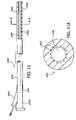
- FIG. 7illustrates a preferred catheter for the selective heating and cooling of patient blood flow employing a wire coil resistance heater and a metal foil cooling element.
- FIG. 8depicts a distal end of a catheter according to the present invention which is inserted into a vessel of a patient.
- FIG. 8Ais a cross-sectional side view of a catheter shown in FIG. 8 taken along lines A-A and depicting a temperature altering region.
- FIG. 9is a side view of an exemplary catheter for heating or cooling a fluid passing through an internal lumen according to the invention.
- FIG. 10is a more detailed view of a distal end of a catheter similarly shown in FIG. 9 .
- FIG. 11is a side view of an alternative catheter for heating a fluid passing through an internal lumen according to the invention.
- FIG. 11Ais a side view of the catheter of FIG. 11 taken along lines A-A.
- FIG. 12is a side view of another alternative embodiment of a catheter for heating or cooling a fluid passing through an internal lumen and having a plurality of perfusion orifices for allowing body fluids to enter into the internal lumen according to the invention.
- FIG. 13is a cutaway side view of a portion of a catheter similarly illustrated in FIG. 12 showing a plurality of flaps which are closed to prevent body fluids from entering into the internal lumen when a liquid is externally injected into the lumen.
- FIG. 14illustrates a catheter similarly illustrated in FIG. 13 showing the flaps opening to allow body fluids to enter into the internal lumen when no fluids are externally injected into the lumen.
- FIG. 15is a perspective view of a heat transfer catheter system connected to a patient that may include monitoring devices, a controller, and a thermal catheter with multiple heat transfer portions.
- FIG. 16is a simplified perspective view of a heat transfer catheter system with a controller, disposable components, reusable components, a heat exchange balloon catheter and various sensors.
- FIG. 17Ais a simplified perspective view of a variation of the heat transfer catheter of the invention in place within the left common carotid artery.
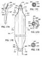
- FIG. 17Bis a simplified perspective view of the distal portion of a finned thermal balloon catheter in accordance with one aspect of the invention having a balloon heat transfer portion for supporting the circulation of heat transfer fluid.
- FIG. 17Cis a simplified cross-sectional view of the catheter illustrated in FIG. 17B taken along line C-C.
- FIG. 17Dis a simplified cross-sectional view of the catheter illustrated in FIG. 17B taken along line D-D.
- FIG. 17Eis a simplified cross-sectional view of the catheter illustrated in FIG. 17B taken along line E-E.
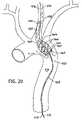
- FIG. 18Ais a simplified perspective view of a variation of the heat transfer catheter of the invention in place within the aorta, the innominate artery, and the right common carotid artery.
- FIG. 18Bis a perspective view in greater detail of the heat transfer catheter of FIG. 18A formed with a blood channeling sleeve defined by openings that may be in communication with a fluid-containing body region.
- FIG. 18Cis a simplified cross-sectional view of the catheter illustrated in FIG. 18B taken along line C-C.
- FIG. 18Dis a simplified cross-sectional view of the catheter illustrated in FIG. 18B taken along line D-D.
- FIG. 18Eis a simplified cross-sectional view of the catheter illustrated in FIG. 18B taken along line E-E.
- FIG. 18Fis a simplified cross-sectional view of the catheter illustrated in FIG. 18B taken along line F-F.
- FIG. 18Gis a simplified cross-sectional view of the catheter illustrated in FIG. 18B taken along line G-G.
- FIG. 19is a simplified illustration of a heat transfer catheter shown in the aorta and having a blood channeling sleeve with a proximal opening in the descending aorta and a distal opening in the left common carotid artery.
- FIG. 20is a simplified perspective view of a variation of the heat transfer catheter of the invention formed with an elongated shaft and a tapered catheter body with spiral shaped fins, and located in the aorta and left common carotid artery.
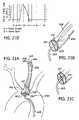
- FIG. 21Ais a simplified perspective view of another variation of the thermal catheter formed with an occlusive shoulder and valve assembly.
- FIG. 21Billustrates a proximal or distal sleeve valve in a closed position for a thermal catheter of the type shown in FIG. 21A .
- FIG. 21Cillustrates a proximal or distal sleeve valve in an open position for a thermal catheter of the type shown in FIG. 21A .
- FIG. 21Dprovides a graphical representation of a heartbeat cycle with aortic blood flow measured against the synchronous opening and closing of a sleeve valve similarly shown in FIGS. 21A-C .
- FIG. 22is a heat transfer catheter with a plurality of heat transfer regions that may be configured for placement in the aortic region.
- FIG. 23Ais a simplified perspective drawing of a version of the heat exchange catheter of the invention having an entry for cooled blood into a central lumen, the distal end of the central lumen inserted into the coronary ostium.
- FIG. 23Bis a cross-sectional view of FIG. 29 taken along lines B-B.
- FIG. 24Ais a simplified perspective view of a finned thermal balloon catheter, the fins being inflatable balloon lobes.
- FIG. 24Bis a simplified cross-sectional view taken along the line B-B in FIG. 24A .
- FIG. 24Cis a simplified cross-sectional view taken along the line C-C in FIG. 24A .
- FIG. 24Dis a simplified cross-sectional view taken along the line D-D in FIG. 24A .
- FIG. 24Eis a simplified cross-sectional view taken along the line E-E in FIG. 24A .
- FIG. 24Fis a simplified cross-sectional view taken along the line F-F in FIG. 24A .
- the present inventionprovides methods and apparatus for selectively controlling regional and whole body temperature by warming or cooling a body fluid such as blood in situ and directing the warmed or cooled body fluid to a desired location.
- a catheter having a heat exchangerwhich may be, for example, a balloon with fins, is inserted into a fluid containing portion of the patients body, for example, a blood vessel.
- a blood channeling sleeveis mounted over the heat exchanger and is open at both its proximal end (closest to the insertion point) and its distal end (farthest along the catheter from the insertion point).
- the distal end of the sleeveis placed so that fluid such as blood that enters the proximal end of the sleeve flows in heat transfer proximity past the heat exchanger.
- Heat exchange proximityrequires sufficient proximity for effective heat exchange to occur and depends on such factors as the chemical and physical make-up of the blood, the rate of flow past the heat exchange surface, the pattern of blood flow past the heat exchanger, (laminar flow, turbulent flow, and the like), the difference in temperature between the heat exchange surface and the blood, the material of which the heat exchange surface is made, and the proximity between the heat exchange surface and the blood.
- target tissuesuch as the brain
- the inventionwhen inducing hypothermia or hyperthermia, provides for heating or cooling the target tissue to the desired temperature and maintaining that temperature by controlling the heat exchange catheter.
- different regionsmay be controllably maintained at temperatures different from each other by controlling different heat exchange catheters at different locations with the patient's body.
- the temperature of the target tissuemay be maintained at a desired temperature, for example, mildly hypothermic, while the core temperature of the body may be monitored and maintained at a different temperature, for example, normothermic (37° C.) or nearly normothermic, by use of a separate heat exchange catheter or an additional heat exchange region located on the same heat exchange catheter.
- FIG. 1depicts a distal portion 15 of a heat exchange catheter 10 .
- the cathetermay be inserted through the patient's skin into a blood vessel BV. Blood flow through the vessel is indicated in FIG. 1 by a set of flow arrows F.
- the cathetermay be inserted into a relatively large blood vessel, e.g., a femoral artery or vein, a jugular vein, since these vessels provide numerous advantages in that they are readily accessible, provide safe and convenient insertion sites, and have relatively large volumes of blood flowing through them. In general, large blood flow rates facilitate quicker heat transfer into or out of the patient.
- a catheter suitable for insertion into a vessel of this sizecan be made quite large relative to catheters intended for insertion into other regions of the vascular system. Atherectomy or balloon angioplasty catheters are sometimes used to clear blockages from the coronary artery and similar vessels. These catheters commonly have external diameters in the range between 2 and 8 French. However, a catheter formed in accordance with this aspect of the invention may have an external diameter of about 10 French or more, although this dimension may obviously be varied a great deal without departing from the basic principles of the invention.
- the cathetermay be small enough so that the puncture site can be entered using the percutaneous Seldinger technique, a technique well known to medical practitioners. To avoid vessel trauma, the catheter will usually be less than 12 French in diameter upon insertion. Once in the vessel however, the distal or working end of the catheter can be expanded to any size so long as blood flow is not unduly impeded. Additionally, the femoral artery and vein and the jugular vein are relatively long and straight blood vessels. This will allow for the convenient insertion of a catheter having a temperature controlled region of considerable length. This is of course advantageous in that more heat may be transferred at a given temperature for a catheter of a given diameter if the length of the heat transfer region is increased.
- FIG. 2depicts still another means for transferring heat to or from the distal end of a catheter.
- catheter shaft 20has two lumens running through it. Fluid flows from the proximal end of the catheter through in-flow lumen 60 , through a heat transfer region 62 , and back out through out-flow lumen 64 .
- heatmay be transferred either to or from the patient's blood stream which flows in heat transfer proximity to the heat transfer region.
- the heat transfer region 62may be in the form of a balloon 70 .
- Use of a balloonmay be advantageous in some embodiments to provide an increased surface area through which heat transfer may take place.
- Balloon inflationis maintained by a pressure difference in the fluid as it flows through in-flow lumen 60 and out-flow lumen 64 .
- the balloonshould be inflated to a diameter somewhat less than that of the inside diameter of the blood vessel so as not to unduly impede the flow of blood through the vessel.
- FIG. 3depicts a catheter having an internal resistance heating element 28 and a balloon 70 , which is shown inflated.
- the balloon surfacemay be provided with structures that increase the surface area available for heat transfer, i.e. fins.
- the increased surface area provided by the inflated balloonis augmented by the presence of a set of longitudinal fins 75 on the surface of the balloon.
- longitudinal fins 75 , radial ribs 77 , or one or more spiral fins 79may be disposed directly on the body 20 of a catheter. Longitudinal ribs may be advantageous because they tend to restrict blood flow through the vessel less than other configurations.
- these ribsinsure that the balloon will not substantially block the flow of blood through the vessel because a flow path may be maintained between the ribs even when the balloon is inflated.
- Inclusion of a balloon on a catheter employing resistance heatingallows for designs in which current is conducted through the fluid which fills the balloon.
- a catheter according to the present inventionmay be designed and configured to optimize the rate of heat transfer between the catheter and blood flowing through the vessel. While a large surface area is desirable in order to maximize heat transfer, the catheter should be appropriately configured and sized to minimize restriction to flow through a blood vessel. Furthermore, the temperature of the catheter should be carefully controlled to prevent undesirable chemical changes within the blood. This is especially important when applying heat to the blood as blood is readily denatured by even moderately high temperatures.
- the exterior temperature of a catheter for warming bloodshould generally not exceed about 42° C.-43° C. It is estimated that a catheter whose surface temperature is controlled between 37° C. and 42° C. will provide a body core warming rate of approximately one to two degrees Celsius per hour in a patient starting out with severe hypothermia.
- This estimateis highly dependent on a number of factors including the rate of blood flow through the vessel, the initial body temperature of the patient, the external surface area of the catheter through which heat is conducted, etc.
- the actual rate achievedmay vary substantially from the above estimate.
- the above estimateprovides a starting point for a rough estimate as to the level of power transferred from the catheter to the patient's body and therefore of the size of the power supply required by the system. Regardless of the exact means of power transmission chosen, resistance heating coil, laser and diffusing tip, direct conduction or fluid circulation, an appropriate power supply will be required to provide heat to or remove heat from the system.
- hypothermiato induce hypothermia, sufficient heat will need to be removed from the blood to lower the temperature of the target tissue, or in the case of whole body hypothermia, to remove more heat than is generated by the body.
- the power required to cool the heat exchangerwill be largely dependent on the efficiency of the cooling device including the dissipation of excess heat from the device to the environment.
- An alternative estimatecan be made by comparing the likely performance of the various embodiments described herein with the power requirements for the external blood warming apparatus presently known.
- Such external warming apparatusgenerally requires a supply of power on the order of 1000-1500 watts and sometimes more.
- a device formed in accordance with the present inventionmay require considerably less power than that.
- the present inventionmay not require an external pump to circulate the blood; this function is provided by the patient's own heart. Accordingly, no power is needed to drive such a pump.
- the present inventionmay be considerably less complicated than external blood warming systems. Known systems circulate the blood over a relatively lengthy path from the patient, through the warming element, and back into the patient. More heat may be lost over this lengthy path than in devices described herein.
- the power required by external blood circulation and warming systems of the type previously knowncan be used as a rough estimate of the likely upper limit for power required by a system according to the present invention. It is most likely that such a system may be equipped with a power supply having a capacity somewhere between the two rough estimates described above. It is therefore contemplated that a suitable power supply will be capable of providing peak power somewhere in the range between 100 and 1500 watts, probably being in the range between 300 and 1000 watts. The ranges specified are an estimate of suitable peak power capability.
- the power supplywill most commonly be thermostatically controlled in response to a temperature sensor in the body of the catheter. The actual effective power transmitted to the patient will therefore typically be much less than the peak power capacity of the system power supply.
- the above calculationsrefer primarily to a system for heating the blood.
- a catheter for cooling the bloodthe temperature and power constraints may not be as limiting. Care should be taken to avoid freezing the blood or inducing shock to the patient from excessively rapid cooling.
- the primary component of bloodis essentially water with a number of suspended and dissolved substances. As such, its freezing point is somewhat below 0° C.
- a catheter adapted to cool blood in a hyperthermic patient or to induce an artificial hypothermiawill usually not be operated at temperatures that low. It is presently contemplated that the external surface of such a catheter may be held in the range between about 1° C. and 20° C., although the actual temperature could vary between about 0° C. and the patient's current body temperature.
- the surface temperature of the balloonmay vary along its length as it gives off heat to the blood.
- a balloonmay vary in temperature as much as 12° C. or more along its length.
- Another aspect of the present inventionfurther provides methods for both raising the body temperature of initially hypothermic patients and lowering the body temperature of patients who are initially hyperthermic, or for whom the body temperature is to be lowered below normal for some other purpose.
- this aspect of the inventionspecifically provides for reversing the heat transfer process to maintain the target tissue at the selected temperature.
- a sample control schemeis provided herein for either warming or cooling target tissue to a preferred temperature and maintaining the tissue at about the preferred temperature.
- the control schemeis described by the flow chart shown in FIG. 5 and illustrated with the graph shown in FIG. 6 .
- a preferred temperatureis pre-selected for the target temperature, for example a temperature of 31° C. for the brain tissue.
- This pre-selected temperatureis communicated to a control unit, for example by setting a desired temperature on a control unit for a heat exchange catheter.
- a heat exchange cathetercapable of either removing heat from the blood or adding heat to the blood is inserted so that it is in heat exchange proximity with blood in a blood vessel that delivers blood to a target location such as the brain.
- the catheteris controlled by the control unit described above that may turn the heat exchanger off or on and may control the heat exchanger to heat or cool the blood which is in heat exchange proximity with the heat exchanger.
- the temperature of the brainis monitored, for example by a temperature probe inserted into the brain tissue or by measuring temperature at some proxy location such as the tympanic membrane or nasal cavity provides a temperature measurement that represents the brain temperature. This results in a sensed temperature measurement that is communicated to the controller.
- An upper variance set pointis determined, for example 1 ⁇ 2 degree above the pre-selected temperature, and communicated to the controller. In this example, that would result in an upper variance set point of 311 ⁇ 2°.
- a lower variance set pointis also determined and communicated to the controller, for example 1 ⁇ 2 degree below the pre-selected temperature, resulting in this example in a lower variance set point of 301 ⁇ 2°.
- the sensed temperature of the target tissueis compared with the pre-selected temperature. If the sensed temperature is above the pre-selected temperature, the cooling continues. If the sensed temperature falls to the pre-selected temperature or below, then the controller acts to turn the heat exchanger off. After the heat exchanger is turned off, the temperature of the target tissue is again measured to obtain a sensed temperature. If the sensed temperature is above the upper variance set point, the controller acts to cause the heat exchanger to begin cooling again. This cooling continues until the temperature again reaches the pre-selected temperature. At this point, the controller once again acts to turn the heat exchanger off.
- the temperaturewill oscillate between the preferred temperature and the upper variance set point, in this example, between 31° C. and 311 ⁇ 2° C. as illustrated by section A of FIG. 6 .
- the temperature of the target tissuemay continue to fall spontaneously after the heat exchanger is turned off, for example if the brain tissue is giving off more heat to the environment than is generated by the brain. In such a situation the sensed temperature may continue to fall until it is below the lower variance set point. If it does, the controller acts to cause the heat exchanger to add heat to the blood and thus to the target tissue until the sensed temperature is again at the pre-selected temperature. The controller then turns the heat exchange catheter off. If the temperature again falls until it reaches a temperature below the lower variance set point, the process is repeated. If this situation repeats, it may be seen that the temperature will oscillate between the pre-selected temperature and the lower variance set point, in this example, between 31° C. and 301 ⁇ 2° C. as illustrated by section B of FIG. 6 .
- the pre-selected temperature and upper and lower variance set pointsmay be different than those described above.
- the discussion abovewas an example of cooling the target tissue to a temperature below normothermic.
- a pre-selected temperature above normothermicmay also be selected, and a heat exchanger which is controlled to both add heat to the blood or remove heat from the blood may, through use of the same control scheme, maintain the temperature of the target tissue at the preferred temperature within the upper and lower variance set points around a pre-selected temperature above normothermic.
- a patient that is hypothermicmay be rewarmed to normothermia by setting the preselected temperature in the control scheme illustrated to 37° which will cause the heating element to warm the blood until the sensed temperature reaches 37°.
- the anticipation and prevention of temperature overshootmay be accomplished as described in U.S. patent application Ser. No. 08/584,013 previously incorporated herein by reference.
- the stepsare all stated as discrete actions, such as measuring the temperature of the target tissue or comparing sensed and pre-selected temperatures, but it may be readily understood by one of skill in the art that the actions may be relatively continuous.
- control criteria other than the temperature of the target tissuemay be substituted and controlled, for example blood pressure or cranial pressure, or temperature derived from some other location, and two control schemes as described may be simultaneously instituted for different locations in the patient, for example, to cool a region such as the brain and maintain that region in a relatively stable cooled condition while simultaneously warming the core temperature of the patient to normothermic and maintaining the patient's core temperature relatively stable at a normothermic temperature.
- the method of affecting the target tissue's temperature discussed abovewas cooling the blood upstream from the target tissue, but it may be appreciated that other methods of heating and cooling, for example heating or cooling cerebrospinal fluid circulating around the brain or spinal cord may be employed.
- the systemmay comprise a catheter 100 having a proximal end 102 , a distal end 104 , a heat-generating surface 106 near the distal end, and a heat-absorbing surface near the distal end 108 .
- the heat-generating surface 106may include any of the heat transfer components described above, particularly a wire coil resistance heater as shown having from 50 to 1000 windings, typically spaced-apart from 0.1 mm to 1 mm.
- the total length of the cathetermay range from 15 cm to 50 cm, and may measure from about 1 mm to 5 mm in diameter.
- the windingsmay extend over a total distance in the range from 10 cm to 20 cm near the distal end.
- the heat-absorbing surfacemay be a thermally conductive metal foil, typically composed of a biologically compatible thermally conductive metal, such as gold, silver, aluminum, or the like. Copper may also be useful, but should be treated or encapsulated in order to enhance its biocompatibility.
- the metal foilmay be thin in order to enhance flexibility of the catheter body, typically having a thickness in the range from 0.001 mm to 0.01 mm.
- the heat-absorbing surface 108may be conductively coupled to a cooler located externally of the catheter, typically in a control unit 120 as described below. In the illustrated embodiment, the surface 108 is coupled by a thermally conductive core member 110 composed of a flexible rod or wire formed from one of the thermally conductive metals described above.
- thermal couplingcan be achieved by extending the surface 108 proximally so that the proximal end of the surface can be coupled to the cooler. In the latter case, it may be preferable that the proximal portions of the surface 108 be thermally insulated to prevent cooling outside of the blood circulation.
- the systemmay further comprise a control unit 120 which typically provides both the heat-generator and the cooler for coupling to the catheter 100 .
- the heat-generatormay also comprise a direct current source for coupling to the resistance heater on the catheter.
- the direct current sourcewill be a commercially available, temperature-controlled DC power supply, typically operating at a voltage in the range from 10 VDC to 60 VDC and a current output in the range from 1 A to 2.5 A.
- the power supplymay be controlled to maintain the surface temperature of the heating surface 106 in the range from 40° C. to 42° C. As discussed above, the surface temperature should not exceed 42° C. in order to prevent damage to blood components. Other desirable characteristics of the heat exchange surface are described above.
- the temperature of the heat exchange surfacecan also be controlled based on measured blood temperature and/or measured body temperature.
- Blood temperaturecan be measured by temperature sensors present on the catheter.
- a temperature sensor 112may be located on the catheter spaced-apart from the heat exchange surfaces 106 and 108 .
- the temperature sensor 112may be located either upstream or downstream from the heat exchange surfaces based on the direction of blood flow and depending on the manner in which the catheter is introduced to the patient.
- a pair of temperature sensorscould be provided, one disposed on each side of the heat exchange surfaces in order to measure both upstream and downstream blood temperatures.
- the cathetermay also include a temperature sensor (not shown) coupled directly to the heat-generating surface 106 so that the temperature of the surface may be directly controlled.
- the cooler in control unit 120may be any type of refrigeration unit capable of removing heat from the heat-absorbing surface 106 at a rate sufficient to cool the blood at a desired rate. Typically, the cooler may be rated at from 150 W to 350 W.
- the coolerwill be a thermoelectric cooler, such as those commercially available from Melcor Thermoelectrics, Trenton, N.J. 08648.
- the coolermay be directly coupled to the core element 110 so that direct heat conduction from the heat-absorbing surface 108 may be effected to the cooler in control unit 120 .
- the temperature of the cooling surface 108may be less critical than that of the heating surface 106 with regard to this aspect of the invention, but will usually be maintained in the range from 0° C. to 35° C. preferably being below 30° C.
- the temperature of the cooling surfacemay be directly controlled within this range, or alternatively, the system may be designed so that the cooling temperature operates approximately within this range based on the total system characteristics.
- the control unit 120may further include one or more temperature controllers for controlling the temperature of the heat-generating surface 106 and the heat-absorbing surface 106 based on the blood temperature and/or the body temperature. At a minimum, the control unit 120 may control the temperature of the heat-generating surface 106 within the range set forth above, and may monitor at least one of the patient blood temperature and patient body temperature in order to reverse the heating or cooling mode as discussed above. With respect to the control scheme described in FIG. 10 , for example, the system may operate in an on-off mode where for example hypothermic patients are initially treated by warming the blood at a constant surface temperature rate until a target temperature is reached. When the target temperature is reached, power to the heat-generating surface 106 is turned off.
- the systemis operated in the cooling mode until the excess body temperature is lowered.
- the cooling and warming modesare reversed.
- the temperature control schemes of the present inventioncould be substantially more sophisticated.
- the power input to warm the patientcould be controlled based on proportional, derivative, or integral control schemes which will typically provide for a tapering of the heat transfer rate as the patient's core or regional body temperature approaches the desired target level.
- cascade control schemesbased on both patient blood temperature and patient body temperature could be devised. Such control schemes, for example, could be adapted both for warming the patient and cooling the patient with mathematical models of typical patient physiological characteristics being taken into account in preparing the control schemes. However, a simple off-on control scheme that is capable of reversing the heat transfer mode if the target temperature is exceeded by more than a safe amount will be sufficient.
- Another aspect of the inventionprovides methods and apparatus for regulating the temperature of a fluid that is to be delivered to a target location within a patient while the fluid is within the body.
- the regulation of the fluid temperature in this mannerlends itself to a variety of applications including heating or cooling the temperature of drugs, solutes, or blood before their delivery to a target site. Regulation of the temperature of the injected fluid may also find use in regulating the temperature of the target location itself in preparation for various medical procedures, including neurosurgical procedures within the brain.
- the methods and apparatusallow for the temperature of tissue within a patient's body temperature to be controlled by warming or cooling the patient's blood in situ. By warming or cooling the patient's blood that subsequently flows to that tissue, the temperature of the tissue in question may thereby be increased or decreased as desired.
- Such methods and apparatustherefore provide a convenient therapy for treating hypothermia or hyperthermia, or for inducing regional cooling or heating.
- FIG. 8depicts a distal end 210 of a catheter 212 formed in accordance with another aspect of the present invention.
- the catheter 212may be positioned within a blood vessel BV. Blood flow through the vessel is indicated in FIG. 8 by a set of arrows F.
- the distal end 210 of the catheter 212may include a temperature altering region 214 although it will be appreciated that the temperature altering region may be located anywhere between the proximal and the distal catheter end. Techniques for inserting catheters into various blood vessels such as the Seldinger technique mentioned above, are well known among medical personnel.
- the catheter 212may be manufactured in various sizes depending upon the particular application.
- the catheter 212will preferably be flexible to allow the catheter to be moved through various vessels within a patient, and may be positioned in the body preferably with the assistance of a guidewire.
- the catheter 212may include an internal lumen 216 .
- a temperature altering mechanism 218may be provided adjacent the luminal wall of the lumen 216 at the temperature altering region 214 .
- the temperature altering mechanism 218is illustrated schematically and may comprise a variety of mechanisms that are employed to either heat or cool the luminal wall of the lumen 216 to heat or cool the fluid passing through the lumen 216 at the temperature altering region 214 .
- Exemplary mechanisms for heating or cooling the luminal wallmay include heated or cooled fluids passing through the catheter 212 near the luminal wall, resistive elements disposed within the catheter 212 , laser energy that is supplied to the temperature altering region, various chemicals disposed within the catheter body, thermoelectric crystal, and the like.
- the temperature altering mechanism 218may be configured to heat a fluid passing through the temperature altering region so that its temperature will be heated by at least 5° C. to about 42° C.
- the temperature altering mechanism 218may be configured to cool the fluid by at least 7° C. to about 30° C.
- the temperature altering mechanism 218may be designed to optimize the rate of heat transfer between the catheter and a fluid flowing through the internal lumen. Further, the temperature of the catheter may be carefully controlled to prevent undesirable chemical changes within the blood.
- the temperature of the luminal wall for warming bloodshould generally not exceed about 42° C. to 43° C.
- the amount of energy that may be supplied to heat a patient's core body temperatureis described in U.S. Pat. No. 5,486,208, previously incorporated by reference herein.
- the temperature altering mechanism 218may be also arranged within the catheter 212 so that the temperature of the luminal wall may be heated or cooled without substantial direct heating of an outer surface of the catheter. In this way, the catheter 212 may be employed to selectively heat or cool a specific target site by simply positioning the distal end of the catheter at the target site and introducing a fluid through the lumen 216 .
- a catheter 220 formed in accordance with this aspect of the inventionmay circulate a heat transfer fluid to alter the temperature of a fluid passing through the catheter.
- the catheter 220comprises a catheter body 222 having a proximal end 224 and a distal end 226 .
- a lumen 228extends between the proximal end 224 and the distal end 226 .
- a proximal port 230is a proximal port 230 through which various fluids may be introduced into the lumen 228 from outside of a patient.
- Passing through the catheter body 222is a first fluid path 232 and a second fluid path 234 as particularly shown in FIG. 10 .
- a first port 236is in communication with the first fluid path 232 and a second port 238 is in communication with the second fluid path 234 .
- a heated or cooled heat transfer fluidmay be introduced into the first port 236 where it passes through the first fluid path 232 adjacent to the lumen 228 .
- heat transfer fluidpasses through the first fluid path 232 , heat is transferred either to or from a fluid passing through the lumen 228 to heat or cool the fluid to a desired temperature before exiting the catheter body 222 .
- the heat transfer fluidcirculates back through catheter body 222 through the second fluid path 234 where it exits the second port 238 .
- FIGS. 11 and 11Aprovide illustrations of yet another variation of the invention that includes a catheter 240 with resistive heating to heat a fluid passing through the catheter.
- the catheter 240comprises a catheter body 242 having a proximal end 244 and a distal end 246 .
- a lumen 248passes through the catheter body 242 between its proximal end 244 and distal end 246 .
- a proximal port 250is provided to facilitate the introduction of fluids into the lumen 248 from outside a patient.
- Disposed within the catheter body 242 near the lumen 248are a plurality of wires 252 as shown in FIG. 17 . These wires 252 may exit the catheter body 242 through a port 254 .
- the wires 252may be also connected to either a DC or low frequency AC power supply. As electrical current passes through the wires 252 , some of the energy is dissipated as heat to heat the luminal wall. Alternatively, a radio frequency or RF power supply may be employed to supply power to electrodes disposed within the catheter body 242 to heat the luminal wall.
- a catheter 256may be employed to heat or cool an externally injected fluid, to heat or cool a body fluid in situ, or a combination of both.
- the catheter 256may comprise a catheter body 258 having a proximal end 260 and a distal end 262 . Extending between the proximal end 260 and the distal end 262 is a lumen 264 as shown in FIG. 12 .
- a proximal port 266is also provided at the proximal end 260 to allow various fluids to be injected into the lumen 264 while port 266 is positioned outside a patient.
- a temperature altering region 268which includes a temperature altering mechanism (not shown).
- the particular temperature altering mechanismmay comprise any of those described with respect to other aspects of the invention set forth above or hereafter.
- a fluid which is injected into the port 266will pass through the lumen 264 and have its temperature altered when passing through the temperature altering region 268 in a manner similar to that previously described with other embodiments.
- the catheter body 258may include a plurality of perfusion orifices 270 which extend through the wall of the catheter body to provide fluid paths to the lumen 264 . As shown by the arrows in FIG.
- a body fluidsuch as blood
- a body fluidmay pass through the orifices 270 and into the lumen 264 where it will have its temperature altered at the temperature altering region 268 so that the temperature of the body fluid will be within a desired range when exiting the catheter body 258 at its distal end 262 as shown.
- the luminal wall of the catheter body 258may include a plurality of flaps 272 . These flaps 272 may control the passage of body fluids through the orifices 270 and into the lumen 264 . These flaps 272 or similar structures may be also constructed as described in U.S. Pat. No. 5,180,364, the disclosure of which is herein incorporated by reference.
- a fluidis injected into the lumen 264 at the port 266 , the pressure and direction of flow of the injected fluid will cause the flaps 272 to close over the orifices 270 as shown in FIG. 13 so that essentially only the injected fluid will pass through the temperature altering region 268 .
- the temperature of the injected fluidwill have its temperature altered so that it will be within a desired range when exiting the distal end.
- the pressure of the body fluid within a vesselwill cause the flaps 272 to open to allow the body fluids to flow through the orifices 270 and into the lumen 264 .
- a body fluidsuch as blood
- the configuration of the flaps 272is particularly advantageous in applications where the temperature of a patient's tissue is altered.
- the blood which flows into the lumen 264 via the orifices 270will have its temperature altered by the time it exits the distal end 262 . This may result in whole body temperature alteration, or if the blood is directed to a specific site by the catheter, may result in regional temperature alteration. In the event that a solute or drug is also needed for therapy, it may be introduced into the lumen 264 through the port 266 and have its temperature be substantially the same as the exiting blood temperature. As described above, this aspect of the invention provides methods and apparatus which are useful in regulating the temperature of various fluids while such fluids are within a patient.
- a variety of proceduresmay be performed including the introduction of a drug or solute from outside the patient that may have its temperature altered within the catheter before reaching a target location.
- a fluidmay be heated or cooled within the catheter to in turn heat or cool a specific region of a body structure prior to the performance of a medical procedure.
- the temperature of a patient's body fluid, such as bloodmay be altered in situ to treat a patient suffering from either hypothermia or hyperthermia, or to intentionally induce either whole body or regional hypothermia.
- Another aspect of the present inventionprovides methods and apparatus for regional and whole body temperature modification.
- the lowering of body temperature for selected regionsmay provide a neuroprotective effect particularly in proximity to the brain.
- Selected portions of at least one cathetermay, for example, cool fluids such as blood or cerebral spinal fluid that are in contact with, circulating in, around, or leading to the brain region.
- the cooled body fluidmay be selectively directed to a chosen region of the patient's body for producing a regionally confined cooling effect.
- a patient's whole body temperaturemay be reduced to provide, for example, neuroprotection for the entire brain and other widely spaced tissue such as the spinal cord.
- methods and apparatus provided hereinmay include a heat exchange catheter formed with an increased surface area or a finned section to provide rapid and effective heat transfer.
- a regionally confined thermal transfer region along a catheter body having a longitudinal dimensionmay further provide effective heat transfer with fluids traveling within an inner passageway, while the catheter may further provide a zone of regional cooling or heat transfer along selected portions of the catheter.
- Various combinations of both heating and cooling elementsmay be defined along different portions of a single catheter, or as part of a series or combination of heat exchange devices as similarly described with respect to other aspects of the invention.
- All of these devices and proceduresmay be directed to regional or selected body temperature modification that is particularly suitable for the cooling of the cerebral region, and for inducing an artificial state of hypothermia that may provide therapeutic benefits in the treatment of cerebrovascular injury.
- the systemmay be a simple heat transfer catheter with manual controls, or may be operated by means of a controller that may monitor a number of sensors and control the heat exchange catheter in response to data received form said sensors.
- a heat transfer catheter system directed to this aspect of the inventionmay include a catheter control unit 300 and a heat transfer catheter 302 formed with a combination of at least one heat transfer section.
- the heat transfer section or sectionsare located on that portion of the catheter, as illustrated by section 319 , that is inserted into the patient. This insertion portion is less than the full length of the catheter and extends from the location on the catheter just inside the patient, when the catheter is fully inserted, to the distal end of the catheter.
- the catheter control unit 300may include a fluid pump for circulating a heat exchange fluid or medium within the catheter 302 , and a combination of at least one heat exchanger component for heating and/or cooling circulating fluids within the heat transfer system.
- a reservoir or fluid bag 306may be connected to the control unit 300 to provide a source of heat transfer fluid such as, saline, blood substitute solution or other biocompatible fluid.
- the control unit 300may further receive data from a variety of sensors which may be, for example, solid state thermocouples to provide feedback and patient temperature information from selected organs or portions of the body such as a temperature probes for the brain and head region 308 , a rectal temperature probe 309 , an ear temperature probe 311 , a bladder temperature probe (not shown) and the like. Based upon sensed temperatures and conditions, the control unit 300 may direct the heating or cooling of the catheter in response to input from the sensors.
- the control unit 300may activate a heat exchanger at a first sensed temperature, and may also deactivate the heat exchanger at a second sensed temperature which may be relatively higher or lower than the first sensed temperature or any other predetermined temperature.
- the control unit 300may of course independently heat or cool selected heat transfer sections to attain desired or preselected temperatures in body regions. Likewise the controller may activate more than one heat exchanger to control temperature at particular regions of the patient's body.
- the controllermight also activate or deactivate other apparatus, for example, external heating blankets or the like, in response to sensed temperatures.
- the controllermay function as described above and illustrated in FIGS. 5 and 6 .
- the temperature regulating catheter 302 illustrated in FIG. 15may also provide various zones of cooling and/or heating by circulating heat transfer medium through a series of inlet and an outlet conduits.
- a first and a second fluid path 312 and 314may provide a heat exchanger channel within the catheter, and may be respectively connected to the inlet 316 and outlet 317 of a pump for circulation of a heat transfer fluid to cool the flow of fluid within a selected body region.
- a similar arrangementmay be implemented for heating a selected body region simultaneously or independently from the cooling component of the system.
- the catheter control unit 300may further include a thermoelectric cooler and heater which are selectively activated and deactivated to perform both heating and cooling functions with the same or different heat transfer medium within the closed-loop catheter system.
- a first heat transfer section 318 of at least one temperature regulating catheter 302 and located on the insertion portion 319 of that cathetermay circulate a cold solution in the immediate head region, or alternatively, within a carotid artery or other blood vessel leading to the brain.
- the head temperaturemay be locally monitored with temperature sensors 308 positioned on a relatively proximate exterior surface of the patient or within selected body regions.
- Another or a second heat transfer section 320 of the catheter 302also located on the insertion portion 319 , may circulate a heated solution within a collapsible balloon or otherwise provide heat to other body locations through heating elements other mechanisms described in accordance with other aspects of the invention.
- heat transfer catheter 302may provide regional hypothermia to the brain region for neuroprotective benefits, other parts of the body may be kept relatively warm so that adverse side effects such as shivering may be avoided or minimized. Warming of the body generally below the neck may be further achieved by insulating or wrapping the relatively lower body in a heating pad or blanket 322 while the head region 310 above the neck is cooled. It should be understood of course that multiple heat transfer sections of the catheter 302 may be modified to provide whole body cooling or warming to affect body core temperature, and is not just limited to regional or localized body temperature regulation.
- FIG. 16provides an illustration of the heat transfer catheter system of the invention which includes disposable components including a heat transfer catheter 324 , a disposable heat exchange plate 338 , a pump head assembly 340 , a saline bag 339 , sensors 348 , 344 and a fluid flow line 337 , as well as reusable components including a solid state thermoelectric heater/cooler 342 , a pump driver 343 and various controls for the unit.
- disposable componentsincluding a heat transfer catheter 324 , a disposable heat exchange plate 338 , a pump head assembly 340 , a saline bag 339 , sensors 348 , 344 and a fluid flow line 337 , as well as reusable components including a solid state thermoelectric heater/cooler 342 , a pump driver 343 and various controls for the unit.
- the heat transfer catheter 324is formed with a blood channeling sleeve 325 , a catheter shaft 326 , and a heat exchanger 327 which may be for example a heat exchange balloon operated using closed-loop flow of heat exchange medium.
- the catheter shaftmay be formed with a working lumen 328 for injection of drugs, fluoroscopic dye, or the like, and for receipt of a guide wire 329 for use in placing the heat transfer catheter at an appropriate location in the patient's body.
- the proximal end of the shaftmay be connected to a multi-arm adapter 330 for providing separate access to various channels in the catheter shaft.
- one arm 336may provide access to the central lumen 328 of the catheter shaft for insertion of a guide wire 329 to steer the heat transfer catheter to the desired location.
- the adaptermay contain an arm 332 to connect an inlet flow line 333 to an inlet flow channel (not shown in this Fig.) within the catheter shaft, a separate arm 334 to connect an outlet fluid line 335 to an outlet flow channel (also not shown in this Fig.)
- a dual channel flow line 337may contain both inlet and outlet flow lines 333 , 335 to connect the catheter shaft 326 to a disposable heat exchange plate 338 .
- one of the flow linesfor example the inlet flow line 333 may be connected to a bag 339 of heat exchange fluid 331 to prime the closed-loop heat exchange balloon catheter system as necessary.
- the heat exchange plate 338may include a serpentine pathway 339 for the heat exchange fluid to be pumped through the heat exchange plate by means of a disposable pump head 340 .
- the heat exchange plate including the serpentine pathway and the pump headis configured to install into a reusable master control unit 341 .
- the master control unitmay include a heat generating or removing unit 342 such as a thermoelectric heater/cooler (TE cooler).
- TE cooleris particularly advantageous because the same unit is capable of either generating heat or removing heat by changing the polarity of current activating the unit. Therefore it may be conveniently controlled to supply or remove heat from the system without the need of two separate units.
- the master control unitincludes a pump drive 343 that activates the pump head 340 to pump the heat exchange fluid 331 and cause it to circulate through the heat exchanger 327 and the serpentine path in the heat exchange plate.
- the heat exchange plateis in thermal communication with the TE cooler, and thus the TE cooler may act to heat or cool the heat exchange fluid as that fluid is circulated through the serpentine pathway.
- the heat exchange fluidis circulated through the heat exchanger located in a patient's body, it may act to add or remove heat from the body. In this way the TE cooler may act to affect the blood temperature of a patient as desired.
- the TE cooler and the pumpare responsive to a controller unit 344 .
- the control unitreceives data input through electrical connections 345 , 346 , 347 to numerous sensors, for example body temperature sensors 348 , 349 that may sense temperatures from a patient's ear, brain region, bladder, rectum, esophagus or other appropriate location as desired by the operator who places the sensors.
- a sensor 350may monitor the temperature of the heat exchange balloon, and other sensors (not shown) may be provided as desired to monitor the blood temperature at the distal tip of the catheter, at the proximal tip of the catheter, or other desired location.
- An operator by means of the manual input unit 351may provide the operating parameters of the control system, for example a pre-selected temperature for the brain.
- the parametersare communicated to the control unit 344 by means of a connection 353 between the manual input unit and the control unit.
- the operator using the manual input unitsupplies a set of parameters to the control unit 344 .
- a desired temperature for the brain region and/or the whole body of the patientmay be specified as the pre-selected temperature.
- Datais received from the sensors 348 , 349 indicating for example, a sensed temperature of the patient at the location of the sensors, e.g. the actual core body temperature of the patient or the actual temperature of the brain region.
- Other data inputmay include the actual temperature of the heat exchanger, the temperature of blood at the distal end of the catheter body, or the like.
- the control unitcoordinates the data and selectively actuates the various units of the system to achieve and maintain parameters. For example, it may actuate the TE cooler to increase the amount of heat it is removing if the actual temperature is above the specified temperature, or decreasing the amount of heat being removed if the temperature is below the specified temperature. It may stop the pumping of the heat exchange fluid when the body or regional temperature sensed is the desired temperature.
- the controllermay have a buffer range for operation wherein a target temperature is established, and an upper variance set point temperature and lower variance set point temperature are also set. In this way, the controller may cause the heat exchanger to operate until the target temperature is reached. At that temperature, the controller may suspend the operation of the heat exchanger until either the upper variance set point temperature is sensed or the lower variance set point temperature is reached. When the upper variance set point temperature is sensed, the controller would then activate the heat exchanger to remove heat from the blood stream. On the other hand, if the lower variance set point temperature is sensed, then the controller would activate the heat exchanger to add heat to the blood stream. This control scheme is similar to that illustrated in FIGS. 5 and 6 discussed above.
- Such a control scheme as applied to this systemhas the advantage of allowing the operator to essentially dial in a desired temperature and the system will act to reach that target temperature and maintain the patient at that target temperature.
- a buffer rangeis established so that when the target temperature is reached, the controller will generally not turn the TE cooler on and off or activate and deactivate the pump drive in rapid succession, actions that would be potentially damaging to the electric units in question.
- the controllermay be configured to simultaneously respond to several sensors, or to activate or deactivate various components such as several heat exchangers.
- a controllermight heat blood that is subsequently circulated to the core body in response to a sensed core body temperature that is below the target temperature, and simultaneously activate a second heat exchanger to cool blood that is directed to the brain region in response to a sensed brain temperature that is above the target temperature.
- the sensed body temperatureis at the target temperature and thus the heat exchanger that is in contact with blood circulating to the core body may be turned off by the controller, while at the same time the controller continues to activate the heat exchanger to cool blood that is directed to the brain region.
- Any of the many control schemesthat may be anticipated by an operator and programmed into the control unit are contemplated by this invention.
- An advantage of the system as illustratedis that all the portions of the system that are in contact with the patient are disposable, but substantial and relatively expensive portions of the system are reusable.
- the catheter, the flow path for sterile heat exchange fluid, the sterile heat exchange fluid itself, and the pump headare all disposable. Even if a rupture in the heat exchange balloon permits the heat exchange fluid channels and thus the pump head to come in contact with a patient's blood, no cross-contamination will occur between patients because all those elements are disposable.
- the pump drive, the electronic control mechanisms, the TE cooler, and the manual input unitare all reusable for economy and convenience.
- the sensorsmay be disposable, but the control unit to which they attach is reusable.
- the serpentine pathwaymay be a coil or other suitable configuration
- the sensorsmay sense a wide variety of body locations and other parameters may be provided to the control unit, such as temperature or pressure
- the heat exchangermay be any appropriate type, such as a thermal electric heating unit which would not require the circulation of heat exchange fluid.
- a pumpmight be provided that is a screw pump, a gear pump diaphragm pump, a peristaltic roller pump, or any other suitable means for pumping the heat exchange fluid. All of these and other substitutions obvious to those of skill in the art are contemplated by this invention.
- FIGS. 17A-Eprovide illustrations an embodiment of a heat exchanger of the invention.
- a heat exchange balloon catheter 360 with a finned balloon portion 362may be positioned within at least a portion of the descending aorta 364 and a blood vessel 366 conducting blood flow to the brain region.
- the balloon portion 362may be formed of material that is sufficiently thin to promote effective thermal transfer between heat exchange fluid within the balloon and blood flowing within heat exchange proximity of the balloon, but not excessively elastic to expand and unintentionally obstruct a fluid passageway or blood vessel 366 .
- the use of thin, strong but relatively inelastic materialsuch as PET is desirable to obtain a predictable balloon configuration with adequate heat exchange properties.
- the catheter shaft 368 of the thermal catheter 360 provided hereinmay be placed in a desired location relative to a selected body region or artery 366 by conventional techniques such as guiding catheters or steerable wire over-the-wire technique as known to those of ordinary skill in the field.
- the balloon portion 362 of the catheter 360may support the closed-loop circulation of a heat transfer fluid as described herein.
- the increased surface areamay provide effective heat transfer within a body region by thermal conduction, and may further permit blood continued blood flow without substantial disruption by creating channels exterior of the balloon surface when the balloon is expanded.
- FIG. 17Billustrates a heat exchange balloon 360 mounted on a shaft 368 defined by a longitudinal axis and a plurality of heat transfer fins 369 , 371 , 373 , 375 projecting radially outward from the longitudinal axis 370 of the catheter shaft.
- the heat transfer finsmay be formed, for example, as the lobes of a multi-lobed, collapsible balloon.
- the shaft 368is generally round and in this embodiment includes a working lumen 370 running through the shaft and open at the distal end of the catheter.
- the working lumenmay be used for the injection of medicaments which may include, for example, a thrombolytic agent, an anticoagulant, a neuro-protectant, a barbiturate, a anti-seizure agent, an oxygenated perfusate, a vaso-dilator, an agent which prevents vaso-spasm, an agent to prevent platelet activation, and an agent to deter the adhesion of platelets.
- medicamentsmay include, for example, a thrombolytic agent, an anticoagulant, a neuro-protectant, a barbiturate, a anti-seizure agent, an oxygenated perfusate, a vaso-dilator, an agent which prevents vaso-spasm, an agent to prevent platelet activation, and an agent to deter the adhesion of platelets.
- the working lumenmay be used for the injection of flouroscopic dye, for the receipt of a guide wire 329 , or as a guiding catheter for various diagnostic or therapeutic devices including, for example, an angioplasty catheter, an embolectomy catheter, an occlusion member delivering catheter, an embolization member delivering catheter, an electro-cautery device, or a microcatheter.
- the shaft exterior of the central lumenis divided by a web 372 into two channels, an inlet channel 374 and an outlet channel 376 .
- the shafthas inlet orifices 377 , 378 , 379 communicating between the inlet channel and the interior of the balloon at the distal portion of the balloon.
- the shaftalso has outlet orifices 380 , 381 , 382 communicating between the interior of the balloon and the outlet channel.
- a plug 384is inserted in the outlet channel between the inlet and the outlet orifices.
- the web 372may be removed from the shaft between the plug and the inlet orifices to reduce resistance to flow of the heat exchange fluid in this portion of the shaft.
- a tube with an open round lumenmay be spliced between the plug in the outlet channel and the inlet orifices to provide a channel under the balloon for relatively unobstructed flow of the heat exchange fluid.
- the balloonmay be made of, for example, a single sheet of collapsible thin plastic material 285 sufficiently thin to allow for effective thermal exchange between a heat exchange fluid on the interior of the balloon and blood flowing over the exterior of the balloon. Tacking the material to the shaft as shown at 286 may form lobes of the balloon. Tacking the sheet of plastic to itself in appropriate locations as shown at 287 and 288 may further shape the lobes.
- the lobed shape of the balloon surfaceprovides for significant surface for heat exchange while providing for continued flow past the balloon through the space between the lobes of the balloon.
- heat exchange fluid(not shown) may be pumped under mild pressure into the inlet channel 374 .
- the heat exchange fluidmay be, for example, sterile saline or other biocompatible fluid with appropriate heat transfer characteristics.
- the heat exchange fluidflows down the inlet channel until it reaches the inlet orifices 377 , 378 , 379 at the distal end of the balloon.
- the fluidflows from the inlet channel into the interior of the balloon. It then flows in a proximal direction through the interior of the balloon until it reaches the outlet orifices 380 , 381 , 382 at the proximal end of the balloon.
- the heat exchange fluidthen flows from the interior of the balloon through the outlet orifices and into the outlet channel 376 where it then flows back down the shaft and out of the body.
- a heat exchange fluidmay be circulated through the balloon and either give off heat if the fluid is hotter than the blood flowing past the balloon, or absorb heat from the heat exchange fluid is cooler than the blood.
- FIGS. 18A-Eprovide illustrations of another variation of the invention heat exchange catheter 390 formed with a sleeve having an inner fluid passageway 392 that provides regionally confined thermal transfer.
- the heat transfer catheter 390may comprise a blood channeling sleeve 394 for placement within a fluid-containing body region, the sleeve defined by a proximal region 396 and a distal region 398 formed with an inner fluid passageway 392 defined by at least one relatively proximal opening 395 and at least one relatively distal opening 399 each in communication with the fluid-containing body region for directing the flow of fluid within the catheter body 394 .
- a heat exchangeris internally positioned within at least a portion the sleeve for regionally confined heat transfer with fluid within the inner fluid passageway 392 of the blood channeling sleeve.
- the heat exchanger illustratedis a fluted closed-loop exchanger positioned around the circumference of the interior passageway 392 for circulation of heat exchange fluid as described in greater detail below.
- the temperature regulating catheter 390may be positioned within at least a portion of the aorta 364 and a blood vessel 399 branching off the aorta to direct blood to the brain region.
- the catheteris positioned in the innominate artery, but could equally be positioned, for example, with its distal portion in the right common carotid artery, the left common carotid, the right internal carotid and the left internal carotid among other locations. Blood may therefore be directed into the brain region while passing the heat exchanger positioned within the inner fluid passageway 392 of the catheter body 394 .
- the heat exchangeris configured for cooling blood flowing through the inner passageway 392 and the catheter is positioned as shown in FIG.
- localized hypothermia of the brain regionmay be effectively achieved.
- the temperature regulating catheter 390may be also selected for applicable methods for controlling the temperature of other selected fluid-containing body regions, for example, where the catheter is positioned to selectively direct blood to those regions.
- the cathetermay be formed with a proximal shaft 400 , the proximal shaft having a central working lumen and two arc-shaped lumens in side-by side configuration.
- the two lumenscomprise an inlet lumen 402 and an outlet lumen 403 .
- the blood channeling sleeveis attached to the proximal shaft at a proximal attachment region 404 .
- the sleevecomprises a layer 405 of very thin material such as a PET sheet formed into a large tube-like configuration.
- the catheter shaftis positioned down the inside of the tube, and the sheet is attached along both the top 406 and the bottom 407 of the catheter shaft along the length of the sleeve.
- the outer layer of the plastic sheet of each of these channelsmay be connected together at the top of the channels 410 to form the tube-like structure that forms the sleeve.
- the two layers of plastic sheet that form each channelmay be connected together at various points or along lines 411 along the length of the sleeve to form pleats 412 , and the inner layer 405 may be loose so that the channels will billow when inflated.
- an orifice 415is formed between the inlet lumen 402 and the inlet channel of the catheter shaft 409 , and similarly an orifice 416 is formed between the outlet lumen 403 and the outlet channel 408 of the sleeve.
- the inlet 409 and outlet 408 channels between the plastic sheetsare connected, so that there is a common space 413 shared by the two channels to allow fluid flowing down the inlet side to be removed through the outlet side as described in greater detail below.
- the catheter shaft under the sleevemay have reduced profile as illustrated in FIG. 18 B so that the sleeve formed of the thin plastic sheets may be folded down onto the catheter shaft and have a suitably low profile.
- two tubesmay be used to create the sleeve.
- the catheter shaftis inserted into a large outer tube, and a slightly smaller inner tube is inserted into the outer tube but over the catheter shaft.
- the outer tubeis sealed along its length on the bottom of the catheter shaft, and the inner tube is sealed along its length on the top of the catheter shaft.
- the inner and outer tubesare sealed to each a line opposite the catheter shaft to form two channels between them.
- the seal opposite the shaftdoes not extend all the way to the distal end which functions to create the common space for communication between the inlet and outlet channels.
- Yet another method of constructing such a deviceis to invert a large tube of thin plastic to create an inner passageway bounded by two layers of thin plastic, with the thin plastic layers essentially attached at their distal end.
- the space between the two plastic layersforms the inlet and outlet channels.
- the catheter shaftmay be placed within the inner passageway, and the two layers sealed to each other and to the catheter shaft along the bottom of the catheter shaft for the length of the inner passageway.
- the two layers of plasticare also sealed to each other along the top of the inner passageway from the proximal opening to a point just short of the distal end of the passageway. This creates an inlet channel 409 and an outlet channel 408 while leaving a common space 413 at the distal end of the sleeve.
- heat exchange fluid(not illustrated) is introduced under pressure into the inlet lumen 402 of the proximal shaft 404 . It is directed down the shaft to the inlet orifice 415 , at which point it enters the inlet channel 409 between the two layers of the plastic sheet on the inlet side. The fluid is then directed down the inlet channel, essentially inflating the billowing pleats of the sleeve somewhat. The fluid enters the common space 413 at the distal end of the blood channeling sleeve, and thereby enters the outlet channel 408 formed between the layers of plastic sheet on the outlet side of the sleeve.
- the fluidtravels back down the length of the sleeve through the pleated channel to the outlet orifice 416 formed between the outlet channel 408 and the outlet lumen 403 in the catheter shaft.
- the fluidthen travels down the outlet channel and out of the body.
- heat exchange fluidmay be circulated through the structure to create heat exchange between blood flowing through the inner passageway in heat exchange proximity with the heat exchange fluid.
- the formation of the inner passageway using a thin plastic sheetsallows blood channeling sleeve to be collapsed to a low profile, for example, wrapping or folding it onto the reduced profile portion of the catheter shaft. This in turn provides a low profile device for insertion into the vascular system.
- the billows created by the pleating of the plastic sheetincreases the surface area for heat exchange between the heat exchange fluid flowing in the catheter body and blood or other body fluid in heat exchange proximity within the interior passageway.
- a heat transfer catheter 420may have a catheter body 422 formed as a blood channeling sleeve forming an inner passageway 423 with a heat exchanger such as a heat exchange balloon catheter 424 positioned within the inner passageway 423 .
- the heat exchangermay be any suitable heat exchanger, but in the embodiment shown the heat exchanger is a heat transfer balloon catheter, for example the type described in the previous sections or depicted in FIG. 17B or FIG. 24A below.
- the heat exchangershould be suitably sized and configured to provide sufficient heat exchange capabilities but allow adequate flow of fluid through the inner passageway.
- the blood channeling sleevehas a proximal section 426 having a proximal opening 428 .
- the wall of the sleeve in the proximal sectionmay additionally form orifices 430 to further enhance perfusion of fluid from the surrounding body portion into the inner passageway.
- the sleevefurther has an intermediate section 432 .
- the wall of the sleeve in the intermediate sectionis generally solid so that it generally will not permit fluid to exit the inner passageway through the wall of the sleeve in the intermediate section.
- the wall of the sleeve in the intermediateand indeed throughout its length, may be formed of a material with thermal insulation properties to thermally insulate fluid within the inner passageway from the tissue such as blood outside of the inner passageway.
- tissuesuch as blood outside of the inner passageway.
- the distal section 434 of the blood channeling sleevehas a distal opening 436 .
- the wall of the blood channeling sleeve at the distal sectionmay form orifices 438 that further enhance the flow of fluid out of the inner passageway and into the surrounding body portion such as a blood vessel.
- the distal end of the sleeve 436may be proximal of the distal end of the heat exchanger 440 , may be co-extensive with the end of the heat exchanger (not shown) or may extend distal of the heat exchanger as is shown in FIG. 26 .
- central working lumen 442that extends from the proximal end of the catheter shaft outside the patient's body to the distal end of the catheter shaft 443 .
- the central lumenmay extend past the distal end of the heat exchange balloon or even past the distal end of the sleeve.
- the working lumenmay be used to accommodate a guide wire or to inject dye or insert a microcatheter for additional procedures such as lysing a clot or performing injections through the microcatheter or any of the other uses for the working lumen as described above, particularly in reference to the working lumen shown in FIG. 17 .
- any of the above uses of the working lumenmay be performed before, after, or even during the cooling of blood within the blood channeling sleeve. It may be one advantage of a catheter of the invention having a working lumen that the working lumen may be used for any of the above purposes at the same time that cooling is taking place and without inhibiting the cooling function of the catheter.
- the heat transfer catheteris placed in a fluid containing body, for example, as illustrated in FIG. 19 , the arterial system.
- the proximal end of the blood channeling sleevemay be, for example, located in the descending aorta 446 .
- the distal end of the catheter bodyis positioned as desired, in the case illustrated, in the left common carotid artery 448 , which delivers blood to the brain.
- the pressure differential between the aorta at the level of the proximal end of the sleeve and the left common carotid artery at the distal end of sleeveis sufficient to cause blood to flow through the sleeve, into left common carotid artery and thence to the brain.
- bloodenters the inner passageway of the blood channeling sleeve located in the aorta, and travels through the inner passageway and in heat exchange proximity with the heat transfer balloon 424 in which heated or cooled heat exchange fluid is circulating.
- the bloodis thus heated or cooled.
- the heated or cooled bloodis then channeled out the distal end of the inner passageway where it flows into the left common carotid artery. If the heat exchanger is cooling the blood, cooled blood would thus be directed into the left common carotid and bath the brain in cooled blood. This, in turn, if maintained for a sufficient length of time, may result in regional cooling of the brain tissue with the advantages of that condition noted above.
- the placement of the proximal opening of the blood channeling sleeve 423 down the descending aorta some distance from the aortic arch 447will provide for a longer path for the blood to travel over the heat exchange balloon catheter in reaching the right common carotid than would be the case if blood were captured and directed through the inner passageway by a blood-channeling sleeve located entirely within the left common carotid artery. This longer flow path provides for increased cooling effect relative to the shorter path.
- the placement of the blood channeling sleeve at least partially in the aortaprovides for the use of a larger heat exchanger, for example a heat exchange balloon of greater diameter, than would be possible if the heat exchange portion of the catheter body was located in the right common carotid artery since the aorta is significantly larger in diameter than the right common carotid artery.
- the distal section 434 of the blood channeling sleevemay also form a relatively tight fit around the blood vessel in which it is located. In this way, the pressure differential between the proximal and distal end of the sleeve is maximized, and essentially all the blood flowing from, for example, the aorta to the carotid artery passes through the inner passageway and is heated or cooled by the heat exchanger.
- the wall of the blood channeling sleevemay form an occlusive shoulder to facilitate the sealing of the artery.
- the heat exchangeris, for example, a heat transfer balloon that holds the walls of the catheter body extended, and the heat exchange balloon has fins or the like that will permit significant blood flow between the heat exchange balloon fins and between the inner walls of the inner passageway and the balloon, most if not all the blood entering the right common carotid artery would pass over the heat exchanger and thus is treated by heating or cooling.
- the catheter 450may be provided with a blood channeling sleeve 452 for the receipt and direction of body fluid such as blood.
- the sleevemay be essentially funnel shaped, having a distal region 454 that is significantly larger in diameter than its distal region 456 .
- the exterior surface of the blood channeling sleevemay form an occlusive shoulder that may be pressed or rest against appropriate anatomical structures such as the interior of the artery in question, so that most or virtually all of the blood entering the artery in question is directed through the interior passageway 464 of the blood channeling sleeve before entering the artery.
- the artery into which the catheter body is insertedis the left common carotid artery, but it may be readily appreciated by those of skill in the art that the distal portion of the blood channeling sleeve may be configured for similar placement in other desired locations.
- the distal regionmay be elongate with a substantially cylindrical shape and terminate in a distal opening 458 .
- the proximal regionmay have a proximal opening 460 which may have a valve 462 for opening or closing the proximal opening or otherwise controlling entrance of the blood to the interior passageway 464 within the catheter body.
- the interior of the proximal region 454contains a heat exchanger.
- the heat exchanger depictedis a series of spiral fins 466 which may contain contains heat transfer balloons or balloon lobes for circulating heat transfer fluid. Alternatively the fins may be other types of heating or cooling mechanisms such as electric resistance heaters.
- the heat transfer cathetermay be provided with a catheter shaft 468 which may be provided with a working lumen 470 which may extend out of the patient's body when the heat exchange catheter is in place, and thus provide for the injection of drugs, fluoroscopic dye, or the like, and may accommodate a guide wire 472 for the placement of the heat transfer catheter.
- the shaftmay also have channels (not shown) for the flow of heat transfer fluid, or contain electrical wires (not shown) to connect to the heat exchangers or sensors (also not shown) on the catheter.
- the heat transfer catheter 450is placed in the desired body location.
- the catheteris placed so that the proximal portion of the blood channeling sleeve 454 is within the aorta 474 and the distal portion 456 is within the left common carotid artery 476 .
- Bloodflows down the aorta (illustrated with the arrows labeled “F”) and may enter the proximal opening 460 of the catheter body if the valve 462 is open.
- the pressure differential between the blood in the aorta and the blood in the left common carotidis sufficient to cause the blood to flow up the inner passageway.
- the bloodflows up the inner passageway it passes in heat exchange proximity with the heat exchange fins 466 and is heated or cooled.
- the heated or cooled bloodis channeled into the left common carotid by the blood channeling sleeve, and ultimately the heated or cooled blood baths the brain. If maintained for a sufficient length of time this may result in regionally heating or cooling of the brain.
- FIG. 21Another embodiment of the heat transfer catheter of the invention is illustrated in FIG. 21 .
- the catheter 490 illustrated in that drawingis provided with a blood channeling sleeve 492 that is configured for placement in the blood vessels of the patient's body, for example the main arteries leading to the brain region 494 .
- the blood channeling sleeveis essentially cylindrical in shape, but may have a slightly enlarged proximal section 496 that creates a shoulder in the catheter body that may act as an occlusive shoulder 498 when the blood channeling sleeve is placed in an artery, such as an artery branching off the coronary arch.
- the blood channeling sleeveis shaped as a tube and forms an inner passageway 500 that extends from the proximal section 496 that begins with a proximal opening 502 to the distal end which terminates at a distal opening. 504 .
- a heat exchangersuch as a fined balloon heat exchange catheter 506 as described and illustrated in FIGS. 17 B and 24 A is located in the catheter body and may be contained entirely within the inner passageway 500 of the sleeve.
- the fins 508provide for added heat transfer surface relative to a cylindrically shaped heat exchange balloon, and also create flow channels between the fins for the flow of blood from the proximal opening, over and between the fins of the heat exchange balloon, and out the distal end of the inner passageway.
- a catheter shaft 509may also be provided as described in conjunction with the other embodiments described above.
- FIGS. 21B-Dillustrate the operation of a control system to regulate the opening and closing of a valve assembly 460 that may be formed along any section of the sleeve 492 such as at the proximal opening 502 in order to control the flow of blood within the inner passageway 500 .
- a bi-leaflet valve 510may be positioned at the proximal opening of the sleeve 492 around the catheter shaft.
- the valve 510may have at least one closed position as shown in FIG. 21B and at least one open position as shown in FIG. 21C .
- Other valvessuch as one-way valves may be selected for the catheter body, and the valve may be opened and closed to a variable degree to control the amount of fluid passing through the sleeve at selected points in time.
- the valve 510may be synchronously opened and/or closed in accordance with the heartbeat of a patient as illustrated by the graph of FIG. 21D . Because aortic blood flow (L/min) is pulsatile and fluctuates at different time intervals during the heartbeat cycle, a valve may be selectively opened when a relatively large amount of blood is released from the heart. At the same time, the valve may be selectively closed to retain the blood within the inner passageway 500 when the blood flow is slower. Alternatively, the valves may be controlled to cause blood to flow more slowly through the inner passageway to allow for all the blood passing in to the artery distal of the catheter body flows slowly over the head exchanger for maximum heating or cooling.
- L/minaortic blood flow
- the valvesmay be controlled to cause blood to flow more slowly through the inner passageway to allow for all the blood passing in to the artery distal of the catheter body flows slowly over the head exchanger for maximum heating or cooling.
- a catheter control unitmay simultaneously monitor body conditions or sensed stimuli such as the heart rate, temperature at various locations, and pressure within the apparatus or within the patient.
- body conditions or sensed stimulisuch as the heart rate, temperature at various locations, and pressure within the apparatus or within the patient.
- the valve 510When the valve 510 is in a closed position ( FIG. 21B ), blood or fluid is retained within the inner passageway 500 and effectively cooled by the internally positioned heat exchanger 506 .
- a valve in a closed positionmay prevent or minimize backflow of cooled fluid away from the brain.
- the valvemay be activated to assume an open position ( FIG. 21C ) to allow the cooled blood to be pushed out of the confined cooling area by the relatively warmer incoming blood.
- the valve 510When the pressure or surge of blood from the heart subsides thereafter, the valve 510 may again close, and this cooling and pumping cycle continues repeatedly until the desired level of regional hypothermia in the brain is achieved.
- FIG. 21Dis a graphic representation of the cycle
- a heat exchange catheter 520includes a heat transfer balloon 524 with a plurality of collapsible cooling fins 522 placed in the aortic 526 region.
- a suitable heat transfer balloon catheter with finshas been previously described.
- the heat exchange cathetermay be provided with a catheter shaft 528 .
- the heat exchange cathetermay have a heating element 530 formed at a different location along the catheter shaft than the cooling balloon 524 .
- the shaft 528may include a pair of longitudinal fluid paths (not shown) for circulating hot heat transfer medium to the heating element as well as an additional pair of fluid paths (not shown) that circulate cold heat transfer medium to the cooling balloon 522 .
- the heating fin 530may include a resistance heater or other heating elements known in the art. In the case of a resistance heating element, electrical current may pass through wires within the shaft (not shown) to the heat-generating element.
- the cooling balloon 522may include an insulated underside 534 . Blood flowing in a certain direction, for example to the brain region, may thus be preferentially cooled relative to blood flowing to other areas of the patient's body, for example to the lower body.
- the heat transfer regionincludes a curved cooling balloon that is thermally insulated along the inner radius of its curvature and thermally conductive along its outer radius of its curvature.
- the cooling balloonmay be placed in the aortic arch. Blood is pumped by the heart into the aorta (indicated by arrows F) and some flows over the top surface 523 of the cooling balloon 522 in heat exchange proximity to the balloon surface. This blood is cooled, and the cool blood then flows naturally to the brain region.
- Blood flowing past the inner, insulated curvature of radius 525is not cooled, and thus blood of normal temperature flows down the aorta and to the lower body. It may be noted that, in the example illustrated, cool blood flows to the brain region through all of the arteries extending from the aortic arch without the need to cannulate each of those arteries. In such a configuration, it is also unnecessary to provide the heat transfer catheter with a blood channeling sleeve since the directional cooling is obtained without using the catheter to direct the cool blood to specific arteries.
- heating and cooling mechanismsmay be formed at various locations along the shaft 528 of the heat transfer catheter 524 .
- multiple heating and cooling cathetersmay be used in combination or cooperatively.
- a common catheter control unitmay monitor and control multiple devices individually or collectively, and may be responsive to one or more sensors (not shown) such as pressure sensors or temperature sensors.
- FIG. 23Another aspect of the invention is illustrated in FIG. 23 whereby heated or cooled blood may be directed to a specific location such as a tumor, or organ such as the heart, through a relatively small vessel.
- a heat transfer catheter 550is provided having a blood channeling sleeve 552 , which sleeve has a proximal opening 554 and a distal end section 552 .
- a heat exchanger 558which may be, for example, a finned heat transfer balloon as described above, is located within the blood channeling sleeve.
- the heat transfer catheterhas a catheter shaft 560 , which extends from at least the interior of the blood channeling sleeve to a distal end 562 .
- the distal section of the sleeveis sealed around the catheter shaft 564 .
- the catheter shaft 560has a perfusion lumen 566 extending between blood inlet orifices 568 , 570 formed in the catheter shaft at a point within the blood channeling above, and the distal end 562 of the shaft.
- the blood inlet orificesprovide fluid communication between the perfusion lumen and the interior 572 of the blood channeling sleeve.
- the heat transfer catheter 560is placed into a patient's vasculature, for example the aorta 574 , and is positioned so that the distal end 562 of the catheter shaft 560 in a desired location, for example, in the coronary ostium.
- the pressure differential between the blood in the aorta at the proximal end of the blood channeling sleeve 552 and the distal end 566 of the catheter shaftcauses blood to flow through the proximal opening of the sleeve, through 554 the inner passageway and in heat transfer proximity to the heat exchanger at which time the blood will be heated or cooled, and into the blood inlet orifices through the central lumen of the catheter shaft and out the distal tip of the central lumen 578 .
- a stream of heated or cooled bloodmay be directed to a specific organ or tissue, for example the heart or tumor, and bath that organ or tissue in the heated or cooled blood. If a sufficient portion of the organ or tissue's blood supply is treated in this manner for a sufficient time, regional heating or cooling of the organ or tissue in question will result.
- the central lumenmay extend from the distal tip 578 to a proximal opening outside the body. In this way the central lumen may function as a working lumen for all applications as previously described including angiography and acting as a guide catheter for angioplasty.
- the central or working lumenmay be sized to function as a guide catheter and allow simultaneous insertion of an angioplasty catheter and infusion of cold blood through the central or working lumen.
- FIG. 24AAn alternative construction to the heat exchange balloon as illustrated in FIG. 17 is shown in FIG. 24A wherein the heat exchange region is formed using a series of three collapsible balloon lobes 902 , 904 , 906 located around a central collapsible lumen 908 .
- a proximal shaft 910is formed having two channels, an inlet channel 912 and an outlet channel 914 .
- the interior of the shaftis divided into two lumens by webs 916 , 917 , but the lumens do not occupy equal portions of the interior of the shaft.
- the inlet channeloccupies about 1 ⁇ 3 of the circumference of the interior
- the outlet channeloccupies about 2 ⁇ 3 of the circumference of the interior for reasons that will be explained below.
- a transition 915is formed between the shaft 910 and the tube 911 forming the central collapsible lumen 908 .
- the outlet channelis plugged 917
- the tube 911is affixed over the shaft 910 by, for example gluing, at the transition 915 , and the shaft ends with the tube (not shown).
- the inlet channel in this portion of the catheteroccupies the entire circumference of the shaft.
- inlet orifices 918 , 920 , 922are formed between the inlet channel and the three collapsible balloons.
- outlet orifices 924 , 926 , 928are formed between the interior of each balloon and the outlet channel in the shaft. As may be seen in FIG. 30D , the configuration of the outlet channel is such that communication with the interior of each of the three balloons is possible.
- heat exchange fluidmay flow down the inlet channel in the shaft 912 , continue down lumen 908 to the distal end of the heat exchange region, exit the lumen through the inlet orifices 918 , 919 , 920 to the interior lumens of the balloon lobes 919 , 921 , 923 , travel back down each of the three balloons and re-enter the shaft through the outlet orifices 924 , 926 , 928 and then down the outlet channel 914 toward the proximal end of the catheter.
- heat exchange fluidmay be circulated through the three balloons to add heat to the blood flowing in heat transfer proximity to the balloons if the heat exchange fluid is warmer than the blood, or to remove heat from the blood if the heat exchange fluid is cooler than the blood.
- the material from which the balloons are madeis made of a material that will permit significant thermal exchange between the heat exchange fluid on the interior of the balloon and the body fluid such as blood flowing in heat exchange proximity to the surface of the balloon.
- One such appropriate materialis very thin plastic material, which may also be made strong enough to withstand the pressure necessary for adequate flow of the heat exchange fluid.
- the same heat exchange balloon of the type described here and in conjunction with FIG. 17may be used to add heat to the blood stream or remove heat from the blood stream depending on the relative temperature of the heat exchange fluid and the blood flowing in heat exchange proximity to the balloon. That is, the same device at the same location may be used alternately to add or to remove heat merely by controlling the temperature of the heat exchange fluid within the device.
- a heat exchange devicemay also be supplied as a kit comprising the heat exchange device and a set of instruction for using the heat exchange device.
- the heat exchange devicemay comprise, for example, a heat exchange catheter as described in this application.
- the instructions for usewill generally instruct the user to insert the heat exchange device into a body fluid containing region and to establish the temperature of the heat exchange device to affect the temperature of the body fluid.
- the instructions for usemay direct the user to heat or cool the body fluid to achieve any of the purposes described in this application.
Landscapes
- Health & Medical Sciences (AREA)
- Life Sciences & Earth Sciences (AREA)
- Public Health (AREA)
- Engineering & Computer Science (AREA)
- Biomedical Technology (AREA)
- Heart & Thoracic Surgery (AREA)
- Animal Behavior & Ethology (AREA)
- General Health & Medical Sciences (AREA)
- Veterinary Medicine (AREA)
- Vascular Medicine (AREA)
- Thermal Sciences (AREA)
- Physics & Mathematics (AREA)
- Pulmonology (AREA)
- Biophysics (AREA)
- Anesthesiology (AREA)
- Hematology (AREA)
- Thermotherapy And Cooling Therapy Devices (AREA)
- Diaphragms For Electromechanical Transducers (AREA)
- Inorganic Insulating Materials (AREA)
- Infusion, Injection, And Reservoir Apparatuses (AREA)
- Apparatus For Radiation Diagnosis (AREA)
- Media Introduction/Drainage Providing Device (AREA)
- External Artificial Organs (AREA)
Abstract
Description
ΔH=Hc+Hi−He
where ΔH is the sum of all heat transferred, Hcis the heat transferred from the catheter to the patient, Hithe heat produced by the patient internally, and Hethe heat lost from the patient to the environment. If one assumes, as will ordinarily be the case in a healthy patient, that the body's internal thermoregulatory system will produce just enough heat to offset heat lost to the environment, then the equation is made simple:
ΔH=Hc.
The above equation can be written in terms of the change in the patient's internal body temperature over time as follows:
mc(ΔT/Δt)=(ΔHc/Δt)
where m is the body mass of the patient, c is the specific heat of the patient's body, (ΔT/Δt) is the time rate of change of the patient's internal body temperature, (ΔHc/Δt) is the time rate of heat delivery from the catheter to the patient. If one assumes a patient having a body mass of 75 kilograms and a specific heat of 4186 joules/° C.-kg (assumes the specific heat of the human body to be the same as that of water, the actual value will be somewhat different), then a warming rate of 1° C. per hour (3600 seconds) will require the catheter to transfer heat to the patient at a rate of about 87 watts (1 watt=1 joule/sec). However, as an estimate of the desirable size of a power supply to be used with a catheter of the present invention, this estimation may be too low. This may be true for a number of reasons. First, it was assumed for the sake of convenience that the patient's internal system would produce an amount of heat equal to that lost to the environment. In a hypothermic patient this will obviously not be the case. Almost by definition, accidental hypothermia occurs when a person's ability to produce heat internally is overwhelmed by heat lost to the environment. The catheter will have to make up the difference so the power level required will need to be greater for that reason alone. Alternatively, to induce hypothermia, sufficient heat will need to be removed from the blood to lower the temperature of the target tissue, or in the case of whole body hypothermia, to remove more heat than is generated by the body. In removal of heat, the power required to cool the heat exchanger will be largely dependent on the efficiency of the cooling device including the dissipation of excess heat from the device to the environment.
Claims (27)
Priority Applications (8)
| Application Number | Priority Date | Filing Date | Title |
|---|---|---|---|
| US11/724,075US7494504B2 (en) | 1993-02-10 | 2007-03-13 | Methods and apparatus for regional and whole body temperature modification |
| US11/931,463US7771460B2 (en) | 1993-02-10 | 2007-10-31 | Methods and apparatus for regional and whole body temperature modification |
| US12/853,864US20110054575A1 (en) | 1993-02-10 | 2010-08-10 | Methods and Apparatus for Regional and Whole Body Temperature Modification |
| US13/182,805US9056004B2 (en) | 1998-08-24 | 2011-07-14 | Methods and apparatus for treating or deterring injuries to or disorders of the brain or spinal cord of a subject |
| US13/183,226US20110270368A1 (en) | 1998-08-24 | 2011-07-14 | Heat Exchange Catheter System |
| US13/367,910US20120283562A1 (en) | 1998-08-24 | 2012-02-07 | In Situ Modification of Therapeutic Agents Using Heat Exchange Catheter System |
| US13/367,956US8968378B2 (en) | 1998-08-24 | 2012-02-07 | Methods for preparing a heat exchange catheter system and for heating and/or cooling a subject's body |
| US14/739,906US20150272777A1 (en) | 1998-08-24 | 2015-06-15 | Devices and Methods for Controlling a Subject's Body Temperature |
Applications Claiming Priority (6)
| Application Number | Priority Date | Filing Date | Title |
|---|---|---|---|
| US1577493A | 1993-02-10 | 1993-02-10 | |
| US08/324,853US5486208A (en) | 1993-02-10 | 1994-10-18 | Method and apparatus for controlling a patient's body temperature by in situ blood temperature modification |
| US08/584,013US5837003A (en) | 1993-02-10 | 1996-01-08 | Method and apparatus for controlling a patient's body temperature by in situ blood temperature modification |
| US09/138,830US6620188B1 (en) | 1998-08-24 | 1998-08-24 | Methods and apparatus for regional and whole body temperature modification |
| US10/626,007US7217282B2 (en) | 1993-02-10 | 2003-07-24 | Methods and apparatus for regional and whole body temperature modification |
| US11/724,075US7494504B2 (en) | 1993-02-10 | 2007-03-13 | Methods and apparatus for regional and whole body temperature modification |
Related Parent Applications (1)
| Application Number | Title | Priority Date | Filing Date |
|---|---|---|---|
| US10/626,007ContinuationUS7217282B2 (en) | 1993-02-10 | 2003-07-24 | Methods and apparatus for regional and whole body temperature modification |
Related Child Applications (1)
| Application Number | Title | Priority Date | Filing Date |
|---|---|---|---|
| US11/931,463ContinuationUS7771460B2 (en) | 1993-02-10 | 2007-10-31 | Methods and apparatus for regional and whole body temperature modification |
Publications (2)
| Publication Number | Publication Date |
|---|---|
| US20070233212A1 US20070233212A1 (en) | 2007-10-04 |
| US7494504B2true US7494504B2 (en) | 2009-02-24 |
Family
ID=22483860
Family Applications (12)
| Application Number | Title | Priority Date | Filing Date |
|---|---|---|---|
| US09/138,830Expired - LifetimeUS6620188B1 (en) | 1993-02-10 | 1998-08-24 | Methods and apparatus for regional and whole body temperature modification |
| US09/739,427Expired - LifetimeUS6497721B2 (en) | 1993-02-10 | 2000-12-15 | Method and apparatus for regional and whole body temperature modification |
| US09/739,134Expired - Fee RelatedUS6527798B2 (en) | 1993-02-10 | 2000-12-15 | Method and apparatus for regional and whole body temperature modification |
| US10/626,007Expired - Fee RelatedUS7217282B2 (en) | 1993-02-10 | 2003-07-24 | Methods and apparatus for regional and whole body temperature modification |
| US11/724,075Expired - Fee RelatedUS7494504B2 (en) | 1993-02-10 | 2007-03-13 | Methods and apparatus for regional and whole body temperature modification |
| US11/931,463Expired - Fee RelatedUS7771460B2 (en) | 1993-02-10 | 2007-10-31 | Methods and apparatus for regional and whole body temperature modification |
| US12/853,864AbandonedUS20110054575A1 (en) | 1993-02-10 | 2010-08-10 | Methods and Apparatus for Regional and Whole Body Temperature Modification |
| US13/182,805Expired - Fee RelatedUS9056004B2 (en) | 1998-08-24 | 2011-07-14 | Methods and apparatus for treating or deterring injuries to or disorders of the brain or spinal cord of a subject |
| US13/183,226AbandonedUS20110270368A1 (en) | 1998-08-24 | 2011-07-14 | Heat Exchange Catheter System |
| US13/367,956Expired - Fee RelatedUS8968378B2 (en) | 1998-08-24 | 2012-02-07 | Methods for preparing a heat exchange catheter system and for heating and/or cooling a subject's body |
| US13/367,910AbandonedUS20120283562A1 (en) | 1998-08-24 | 2012-02-07 | In Situ Modification of Therapeutic Agents Using Heat Exchange Catheter System |
| US14/739,906AbandonedUS20150272777A1 (en) | 1998-08-24 | 2015-06-15 | Devices and Methods for Controlling a Subject's Body Temperature |
Family Applications Before (4)
| Application Number | Title | Priority Date | Filing Date |
|---|---|---|---|
| US09/138,830Expired - LifetimeUS6620188B1 (en) | 1993-02-10 | 1998-08-24 | Methods and apparatus for regional and whole body temperature modification |
| US09/739,427Expired - LifetimeUS6497721B2 (en) | 1993-02-10 | 2000-12-15 | Method and apparatus for regional and whole body temperature modification |
| US09/739,134Expired - Fee RelatedUS6527798B2 (en) | 1993-02-10 | 2000-12-15 | Method and apparatus for regional and whole body temperature modification |
| US10/626,007Expired - Fee RelatedUS7217282B2 (en) | 1993-02-10 | 2003-07-24 | Methods and apparatus for regional and whole body temperature modification |
Family Applications After (7)
| Application Number | Title | Priority Date | Filing Date |
|---|---|---|---|
| US11/931,463Expired - Fee RelatedUS7771460B2 (en) | 1993-02-10 | 2007-10-31 | Methods and apparatus for regional and whole body temperature modification |
| US12/853,864AbandonedUS20110054575A1 (en) | 1993-02-10 | 2010-08-10 | Methods and Apparatus for Regional and Whole Body Temperature Modification |
| US13/182,805Expired - Fee RelatedUS9056004B2 (en) | 1998-08-24 | 2011-07-14 | Methods and apparatus for treating or deterring injuries to or disorders of the brain or spinal cord of a subject |
| US13/183,226AbandonedUS20110270368A1 (en) | 1998-08-24 | 2011-07-14 | Heat Exchange Catheter System |
| US13/367,956Expired - Fee RelatedUS8968378B2 (en) | 1998-08-24 | 2012-02-07 | Methods for preparing a heat exchange catheter system and for heating and/or cooling a subject's body |
| US13/367,910AbandonedUS20120283562A1 (en) | 1998-08-24 | 2012-02-07 | In Situ Modification of Therapeutic Agents Using Heat Exchange Catheter System |
| US14/739,906AbandonedUS20150272777A1 (en) | 1998-08-24 | 2015-06-15 | Devices and Methods for Controlling a Subject's Body Temperature |
Country Status (10)
| Country | Link |
|---|---|
| US (12) | US6620188B1 (en) |
| EP (3) | EP1107714B1 (en) |
| JP (2) | JP4738595B2 (en) |
| AT (2) | ATE353204T1 (en) |
| AU (2) | AU772661B2 (en) |
| CA (1) | CA2342107C (en) |
| DE (2) | DE69935074T2 (en) |
| ES (1) | ES2588389T3 (en) |
| IL (1) | IL141431A0 (en) |
| WO (1) | WO2000010494A1 (en) |
Cited By (4)
| Publication number | Priority date | Publication date | Assignee | Title |
|---|---|---|---|---|
| US20090043366A1 (en)* | 2007-08-09 | 2009-02-12 | Radiant Medical, Inc. | Devices and methods for using endovascular cooling to treat septic shock and other disorders |
| US20110276115A1 (en)* | 2004-09-16 | 2011-11-10 | Thomas Lad Merrill | Cooling Guide Catheter And Associated Method Of Use |
| US20110275935A1 (en)* | 1998-08-24 | 2011-11-10 | Zoll Circulation Inc. | Methods and Apparatus for Treating or Deterring Injuries to or Disorders of the Brain or Spinal Cord of a Subject |
| US9320644B2 (en) | 2011-07-25 | 2016-04-26 | Neurosave, Inc. | Non-invasive systems, devices, and methods for selective brain cooling |
Families Citing this family (321)
| Publication number | Priority date | Publication date | Assignee | Title |
|---|---|---|---|---|
| US6110168A (en)* | 1993-02-10 | 2000-08-29 | Radiant Medical, Inc. | Method and apparatus for controlling a patient's body temperature by in situ blood temperature modifications |
| US6849083B2 (en)* | 1993-02-10 | 2005-02-01 | Radiant Medical, Inc. | Method and apparatus for controlling a patients's body temperature by in situ blood temperature modification |
| US6036687A (en)* | 1996-03-05 | 2000-03-14 | Vnus Medical Technologies, Inc. | Method and apparatus for treating venous insufficiency |
| WO1998056310A1 (en)* | 1997-06-09 | 1998-12-17 | Auckland Uniservices Limited | System and method for reducing brain injury particularly in newborn infants |
| US6200312B1 (en)* | 1997-09-11 | 2001-03-13 | Vnus Medical Technologies, Inc. | Expandable vein ligator catheter having multiple electrode leads |
| US7371254B2 (en) | 1998-01-23 | 2008-05-13 | Innercool Therapies, Inc. | Medical procedure |
| US6325818B1 (en) | 1999-10-07 | 2001-12-04 | Innercool Therapies, Inc. | Inflatable cooling apparatus for selective organ hypothermia |
| US6843800B1 (en) | 1998-01-23 | 2005-01-18 | Innercool Therapies, Inc. | Patient temperature regulation method and apparatus |
| US6096068A (en) | 1998-01-23 | 2000-08-01 | Innercool Therapies, Inc. | Selective organ cooling catheter and method of using the same |
| US6491039B1 (en) | 1998-01-23 | 2002-12-10 | Innercool Therapies, Inc. | Medical procedure |
| US6585752B2 (en) | 1998-06-23 | 2003-07-01 | Innercool Therapies, Inc. | Fever regulation method and apparatus |
| US6312452B1 (en) | 1998-01-23 | 2001-11-06 | Innercool Therapies, Inc. | Selective organ cooling catheter with guidewire apparatus and temperature-monitoring device |
| US6251130B1 (en) | 1998-03-24 | 2001-06-26 | Innercool Therapies, Inc. | Device for applications of selective organ cooling |
| US6051019A (en) | 1998-01-23 | 2000-04-18 | Del Mar Medical Technologies, Inc. | Selective organ hypothermia method and apparatus |
| US6974463B2 (en) | 1999-02-09 | 2005-12-13 | Innercool Therapies, Inc. | System and method for patient temperature control employing temperature projection algorithm |
| US6379378B1 (en) | 2000-03-03 | 2002-04-30 | Innercool Therapies, Inc. | Lumen design for catheter |
| US6991645B2 (en) | 1998-01-23 | 2006-01-31 | Innercool Therapies, Inc. | Patient temperature regulation method and apparatus |
| US6383210B1 (en) | 2000-06-02 | 2002-05-07 | Innercool Therapies, Inc. | Method for determining the effective thermal mass of a body or organ using cooling catheter |
| US6464716B1 (en) | 1998-01-23 | 2002-10-15 | Innercool Therapies, Inc. | Selective organ cooling apparatus and method |
| US6471717B1 (en) | 1998-03-24 | 2002-10-29 | Innercool Therapies, Inc. | Selective organ cooling apparatus and method |
| US6364899B1 (en) | 1998-01-23 | 2002-04-02 | Innercool Therapies, Inc. | Heat pipe nerve cooler |
| US6231595B1 (en) | 1998-03-31 | 2001-05-15 | Innercool Therapies, Inc. | Circulating fluid hypothermia method and apparatus |
| US6719779B2 (en) | 2000-11-07 | 2004-04-13 | Innercool Therapies, Inc. | Circulation set for temperature-controlled catheter and method of using the same |
| US7458984B2 (en)* | 1998-01-23 | 2008-12-02 | Innercool Therapies, Inc. | System and method for inducing hypothermia with active patient temperature control employing catheter-mounted temperature sensor and temperature projection algorithm |
| US6261312B1 (en) | 1998-06-23 | 2001-07-17 | Innercool Therapies, Inc. | Inflatable catheter for selective organ heating and cooling and method of using the same |
| US6558412B2 (en) | 1998-01-23 | 2003-05-06 | Innercool Therapies, Inc. | Selective organ hypothermia method and apparatus |
| US6576002B2 (en) | 1998-03-24 | 2003-06-10 | Innercool Therapies, Inc. | Isolated selective organ cooling method and apparatus |
| US6551349B2 (en) | 1998-03-24 | 2003-04-22 | Innercool Therapies, Inc. | Selective organ cooling apparatus |
| US6599312B2 (en) | 1998-03-24 | 2003-07-29 | Innercool Therapies, Inc. | Isolated selective organ cooling apparatus |
| US6602276B2 (en) | 1998-03-31 | 2003-08-05 | Innercool Therapies, Inc. | Method and device for performing cooling- or cryo-therapies for, e.g., angioplasty with reduced restenosis or pulmonary vein cell necrosis to inhibit atrial fibrillation |
| US6905494B2 (en) | 1998-03-31 | 2005-06-14 | Innercool Therapies, Inc. | Method and device for performing cooling- or cryo-therapies for, e.g., angioplasty with reduced restenosis or pulmonary vein cell necrosis to inhibit atrial fibrillation employing tissue protection |
| US7291144B2 (en)* | 1998-03-31 | 2007-11-06 | Innercool Therapies, Inc. | Method and device for performing cooling- or cryo-therapies for, e.g., angioplasty with reduced restenosis or pulmonary vein cell necrosis to inhibit atrial fibrillation |
| US7001378B2 (en) | 1998-03-31 | 2006-02-21 | Innercool Therapies, Inc. | Method and device for performing cooling or cryo-therapies, for, e.g., angioplasty with reduced restenosis or pulmonary vein cell necrosis to inhibit atrial fibrillation employing tissue protection |
| US6685732B2 (en) | 1998-03-31 | 2004-02-03 | Innercool Therapies, Inc. | Method and device for performing cooling- or cryo-therapies for, e.g., angioplasty with reduced restenosis or pulmonary vein cell necrosis to inhibit atrial fibrillation employing microporous balloon |
| US6589271B1 (en) | 1998-04-21 | 2003-07-08 | Alsius Corporations | Indwelling heat exchange catheter |
| US7287398B2 (en)* | 2001-09-25 | 2007-10-30 | Alsius Corporation | Heating/cooling system for indwelling heat exchange catheter |
| US8128595B2 (en)* | 1998-04-21 | 2012-03-06 | Zoll Circulation, Inc. | Method for a central venous line catheter having a temperature control system |
| US6530946B1 (en) | 1998-04-21 | 2003-03-11 | Alsius Corporation | Indwelling heat exchange heat pipe catheter and method of using same |
| US6419643B1 (en) | 1998-04-21 | 2002-07-16 | Alsius Corporation | Central venous catheter with heat exchange properties |
| US6338727B1 (en) | 1998-08-13 | 2002-01-15 | Alsius Corporation | Indwelling heat exchange catheter and method of using same |
| US6149670A (en)* | 1999-03-11 | 2000-11-21 | Alsius Corporation | Method and system for treating cardiac arrest using hypothermia |
| US6645234B2 (en) | 1998-04-21 | 2003-11-11 | Alsius Corporation | Cardiovascular guiding catheter with heat exchange properties and methods of use |
| US7255709B2 (en)* | 1998-04-21 | 2007-08-14 | Alsius Corporation | Intravascular heat exchange catheter with temperature sensor |
| US6458150B1 (en)* | 1999-02-19 | 2002-10-01 | Alsius Corporation | Method and apparatus for patient temperature control |
| US6682551B1 (en)* | 1999-03-11 | 2004-01-27 | Alsius Corporation | Method and system for treating cardiac arrest using hypothermia |
| US6620189B1 (en)* | 2000-02-28 | 2003-09-16 | Radiant Medical, Inc. | Method and system for control of a patient's body temperature by way of a transluminally insertable heat exchange catheter |
| US6610083B2 (en)* | 1998-08-24 | 2003-08-26 | Radiant Medical, Inc. | Multiple lumen heat exchange catheters |
| US6673098B1 (en)* | 1998-08-24 | 2004-01-06 | Radiant Medical, Inc. | Disposable cassette for intravascular heat exchange catheter |
| US6830581B2 (en) | 1999-02-09 | 2004-12-14 | Innercool Therspies, Inc. | Method and device for patient temperature control employing optimized rewarming |
| US7914564B2 (en)* | 1999-02-09 | 2011-03-29 | Innercool Therapies, Inc. | System and method for patient temperature control employing temperature projection algorithm |
| US6869440B2 (en) | 1999-02-09 | 2005-03-22 | Innercool Therapies, Inc. | Method and apparatus for patient temperature control employing administration of anti-shivering agents |
| US6554797B1 (en) | 1999-02-19 | 2003-04-29 | Alsius Corporation | Method and system for patient temperature management and central venous access |
| US6585692B1 (en) | 1999-02-19 | 2003-07-01 | Alsius Corporation | Method and system for patient temperature management and central venous access |
| US6299599B1 (en)* | 1999-02-19 | 2001-10-09 | Alsius Corporation | Dual balloon central venous line catheter temperature control system |
| US6432102B2 (en)* | 1999-03-15 | 2002-08-13 | Cryovascular Systems, Inc. | Cryosurgical fluid supply |
| US6460544B1 (en)* | 1999-03-11 | 2002-10-08 | Alsius Corporation | Method and apparatus for establishing and maintaining therapeutic hypothemia |
| US6726710B2 (en) | 1999-08-16 | 2004-04-27 | Alsius Corporation | Method and system for treating cardiac arrest using hypothermia |
| US7527622B2 (en)* | 1999-08-23 | 2009-05-05 | Cryocath Technologies Inc. | Endovascular cryotreatment catheter |
| US6575966B2 (en)* | 1999-08-23 | 2003-06-10 | Cryocath Technologies Inc. | Endovascular cryotreatment catheter |
| US7320885B1 (en)* | 1999-09-09 | 2008-01-22 | Toudai Tlo, Ltd. | Method of perforating membrane and apparatus therefor |
| WO2001043661A2 (en)* | 1999-12-14 | 2001-06-21 | Radiant Medical, Inc. | Method for reducing myocardial infarct by applicaton of intravascular hypothermia |
| AU2001238434B2 (en)* | 2000-02-28 | 2006-01-19 | Radiant Medical, Inc. | Disposable cassette for intravascular heat exchange catheter |
| US6648906B2 (en) | 2000-04-06 | 2003-11-18 | Innercool Therapies, Inc. | Method and apparatus for regulating patient temperature by irrigating the bladder with a fluid |
| SE0002100D0 (en)* | 2000-06-05 | 2000-06-05 | Jostra Ab | Cerebral tempering |
| US6726708B2 (en) | 2000-06-14 | 2004-04-27 | Innercool Therapies, Inc. | Therapeutic heating and cooling via temperature management of a colon-inserted balloon |
| US6719723B2 (en) | 2000-12-06 | 2004-04-13 | Innercool Therapies, Inc. | Multipurpose catheter assembly |
| US6450987B1 (en) | 2001-02-01 | 2002-09-17 | Innercool Therapies, Inc. | Collapsible guidewire lumen |
| US6544282B1 (en)* | 2001-02-21 | 2003-04-08 | Radiant Medical, Inc. | Inhibition of platelet activation, aggregation and/or adhesion by hypothermia |
| EP1258230A3 (en) | 2001-03-29 | 2003-12-10 | CardioSafe Ltd | Balloon catheter device |
| US8123789B2 (en) | 2002-04-29 | 2012-02-28 | Rohit Khanna | Central nervous system cooling catheter |
| US6699269B2 (en)* | 2001-04-30 | 2004-03-02 | Rohit K. Khanna | Selective brain and spinal cord hypothermia method and apparatus |
| WO2003002044A2 (en)* | 2001-06-27 | 2003-01-09 | Chuwa Tei | Method of inhibiting the proliferation of vascular smooth muscle cells |
| US7150737B2 (en)* | 2001-07-13 | 2006-12-19 | Sci/Med Life Systems, Inc. | Methods and apparatuses for navigating the subarachnoid space |
| US6679906B2 (en) | 2001-07-13 | 2004-01-20 | Radiant Medical, Inc. | Catheter system with on-board temperature probe |
| US20070213793A1 (en) | 2001-08-06 | 2007-09-13 | Radiant Medical, Inc. | Use of endovascular hypothermia in organ and/or tissue transplantations |
| US6692519B1 (en) | 2001-08-06 | 2004-02-17 | Radiant Medical, Inc. | Use of endovascular hypothermia in organ and/or tissue transplantations |
| WO2003015672A1 (en) | 2001-08-15 | 2003-02-27 | Innercool Therapies, Inc. | Method and apparatus for patient temperature control employing administration of anti-shivering |
| US6800068B1 (en) | 2001-10-26 | 2004-10-05 | Radiant Medical, Inc. | Intra-aortic balloon counterpulsation with concurrent hypothermia |
| US6878147B2 (en) | 2001-11-02 | 2005-04-12 | Vivant Medical, Inc. | High-strength microwave antenna assemblies |
| US7128739B2 (en)* | 2001-11-02 | 2006-10-31 | Vivant Medical, Inc. | High-strength microwave antenna assemblies and methods of use |
| CN1596092A (en)* | 2001-12-28 | 2005-03-16 | 坂本哲康 | Whole-body thermotherapy method and device |
| AU2002243488A1 (en)* | 2002-01-09 | 2003-07-30 | Alsius Corporation | Method and system for therapeutic hypothermia |
| US20160193078A1 (en)* | 2002-01-16 | 2016-07-07 | Zoll Circulation, Inc. | Apparatus and Method Of Gastric Cooling Using Balloon Catheter |
| US8840608B2 (en) | 2002-03-15 | 2014-09-23 | The General Hospital Corporation | Methods and devices for selective disruption of fatty tissue by controlled cooling |
| EP1917935B1 (en) | 2002-03-15 | 2011-01-12 | The General Hospital Corporation | Method for selective disruption of fatty tissue by controlled cooling |
| AU2003220474A1 (en)* | 2002-03-21 | 2003-10-08 | Radiant Medical, Inc. | Measuring blood flow rate or cardiac output |
| US8150519B2 (en) | 2002-04-08 | 2012-04-03 | Ardian, Inc. | Methods and apparatus for bilateral renal neuromodulation |
| US7653438B2 (en) | 2002-04-08 | 2010-01-26 | Ardian, Inc. | Methods and apparatus for renal neuromodulation |
| US6685733B1 (en)* | 2002-04-10 | 2004-02-03 | Radiant Medical, Inc. | Methods and systems for reducing substance-induced renal damage |
| US20030216746A1 (en)* | 2002-05-20 | 2003-11-20 | Worthen William J. | Method and system for treating stroke using hypothermia |
| US20050222652A1 (en)* | 2002-06-17 | 2005-10-06 | Atsuo Mori | Catheter for topical cooling and topical cooling device using the same |
| US6866638B2 (en) | 2002-08-12 | 2005-03-15 | Radiant Medical, Inc. | Temperature sensing system with retrograde sensor |
| US7186222B1 (en) | 2002-09-10 | 2007-03-06 | Radiant Medical, Inc. | Vascular introducer with temperature monitoring probe and systems for endovascular temperature control |
| CA2497181C (en)* | 2002-09-12 | 2013-08-13 | Radiant Medical, Inc. | System and method for determining and controlling core body temperature |
| US7179279B2 (en) | 2002-09-30 | 2007-02-20 | Medtronic Physio Control Corp. | Rapid induction of mild hypothermia |
| US7087075B2 (en) | 2002-09-30 | 2006-08-08 | Medtronic Emergency Response Systems, Inc. | Feedback system for rapid induction of mild hypothermia |
| CA2411569A1 (en)* | 2002-11-12 | 2004-05-12 | Ross E. Mantle | Medical device for the extravascular recirculation of fluid in body cavities at controlled temperature and pressure |
| US7056282B2 (en) | 2002-12-23 | 2006-06-06 | Medtronic Emergency Response Systems, Inc. | Coolant control for rapid induction of mild hypothermia |
| US7278984B2 (en)* | 2002-12-31 | 2007-10-09 | Alsius Corporation | System and method for controlling rate of heat exchange with patient |
| US7300453B2 (en) | 2003-02-24 | 2007-11-27 | Innercool Therapies, Inc. | System and method for inducing hypothermia with control and determination of catheter pressure |
| US20050015125A1 (en)* | 2003-03-14 | 2005-01-20 | Mioduski Paul C. | Hyperthermia treatment systems and methods |
| US20040199114A1 (en)* | 2003-04-01 | 2004-10-07 | Alsius Corporation | Intravascular heat exchange catheter with tissue preservative |
| WO2004093756A1 (en)* | 2003-04-24 | 2004-11-04 | Sheldan Medical Device Ltd. | Urethral warming system |
| JP4192040B2 (en)* | 2003-06-11 | 2008-12-03 | 泉工医科工業株式会社 | Balloon pump drive device |
| US20040267338A1 (en)* | 2003-06-25 | 2004-12-30 | Kent Harrison | Targeted tissue cooling within a body |
| US7311703B2 (en) | 2003-07-18 | 2007-12-25 | Vivant Medical, Inc. | Devices and methods for cooling microwave antennas |
| DE10342709A1 (en)* | 2003-09-11 | 2005-04-21 | Biotronik Gmbh & Co Kg | catheter |
| BRPI0414956A (en)* | 2003-10-03 | 2006-11-14 | Pharmacia Corp | compositions of a selective cyclooxygenase-2 inhibitor administered under hypothermic conditions for the treatment of ischemia-mediated central nervous system disorders or lesions |
| US7326195B2 (en)* | 2003-11-18 | 2008-02-05 | Boston Scientific Scimed, Inc. | Targeted cooling of tissue within a body |
| JP4391221B2 (en)* | 2003-12-22 | 2009-12-24 | 有限会社日本エレクテル | High frequency heating balloon catheter |
| US7520862B2 (en) | 2004-02-03 | 2009-04-21 | Neuro Diagnostic Devices, Inc. | Cerebral spinal fluid shunt evaluation system |
| US20060025840A1 (en)* | 2004-08-02 | 2006-02-02 | Martin Willard | Cooling tissue inside the body |
| US20060058859A1 (en)* | 2004-09-16 | 2006-03-16 | Merrill Thomas L | Cooling catheter and method with adjunctive therapy capability |
| US20060064146A1 (en)* | 2004-09-17 | 2006-03-23 | Collins Kenneth A | Heating/cooling system for indwelling heat exchange catheter |
| US20070016272A1 (en)* | 2004-09-27 | 2007-01-18 | Thompson Russell B | Systems and methods for treating a hollow anatomical structure |
| US20060069385A1 (en)* | 2004-09-28 | 2006-03-30 | Scimed Life Systems, Inc. | Methods and apparatus for tissue cryotherapy |
| US20060079820A1 (en)* | 2004-09-30 | 2006-04-13 | Heart Core, L.L.C. | Cervical Immobilization Collar with Arterial Cooling Elements |
| US8672988B2 (en) | 2004-10-22 | 2014-03-18 | Medtronic Cryocath Lp | Method and device for local cooling within an organ using an intravascular device |
| US20060129126A1 (en)* | 2004-11-19 | 2006-06-15 | Kaplitt Michael G | Infusion device and method for infusing material into the brain of a patient |
| US20060175543A1 (en)* | 2005-02-08 | 2006-08-10 | John Elefteriades | Intra-thecal catheter and method for cooling the spinal cord |
| US20060190062A1 (en)* | 2005-02-23 | 2006-08-24 | Worthen William J | System and method for reducing shivering when using external cooling pads |
| US7070612B1 (en)* | 2005-02-23 | 2006-07-04 | Alsius Corporation | System and method for bringing hypothermia rapidly onboard |
| US20060190066A1 (en)* | 2005-02-23 | 2006-08-24 | Worthen William J | System and method for bringing hypothermia rapidly onboard |
| US7425216B2 (en) | 2005-03-01 | 2008-09-16 | Alsius Corporation | System and method for treating cardiac arrest and myocardial infarction |
| US7892269B2 (en) | 2005-04-18 | 2011-02-22 | Zoll Circulation, Inc. | External heat exchange pad for patient |
| US7806915B2 (en) | 2005-04-27 | 2010-10-05 | Zoll Circulation, Inc. | Apparatus and method for providing enhanced heat transfer from a body |
| US7799019B2 (en) | 2005-05-10 | 2010-09-21 | Vivant Medical, Inc. | Reinforced high strength microwave antenna |
| US20060276864A1 (en)* | 2005-06-03 | 2006-12-07 | Alsius Corporation | Systems and methods for sensing patient temperature in temperature management system |
| US8157851B2 (en) | 2005-06-08 | 2012-04-17 | Xtent, Inc. | Apparatus and methods for deployment of multiple custom-length prostheses |
| US20060293732A1 (en)* | 2005-06-27 | 2006-12-28 | Collins Kenneth A | Thermoelectric cooler (TEC) heat exchanger for intravascular heat exchange catheter |
| US20100130937A1 (en)* | 2005-06-30 | 2010-05-27 | Abbott Vascular Inc. | Introducer sheath and methods of making |
| US20080004571A1 (en)* | 2006-06-28 | 2008-01-03 | Abbott Laboratories | Expandable introducer sheath |
| US9352118B2 (en) | 2005-06-30 | 2016-05-31 | Abbott Laboratories | Modular introducer and exchange sheath |
| US8801744B2 (en)* | 2006-06-28 | 2014-08-12 | Abbott Laboratories | Expandable introducer sheath to preserve guidewire access |
| US9168359B2 (en) | 2005-06-30 | 2015-10-27 | Abbott Laboratories | Modular introducer and exchange sheath |
| US9597063B2 (en)* | 2006-06-28 | 2017-03-21 | Abbott Laboratories | Expandable introducer sheath to preserve guidewire access |
| US8440122B2 (en) | 2005-06-30 | 2013-05-14 | Abbott Vascular Inc. | Introducer sheath and methods of making |
| US8359723B2 (en)* | 2005-06-30 | 2013-01-29 | Abbott Vascular Inc. | Introducer sheath and methods of making |
| US7181927B2 (en) | 2005-07-01 | 2007-02-27 | Alsius Corporation | Primary heat exchanger for patient temperature control |
| US7951182B2 (en) | 2005-07-14 | 2011-05-31 | Zoll Circulation, Inc. | System and method for leak detection in external cooling pad |
| JP4776317B2 (en)* | 2005-07-15 | 2011-09-21 | 有限会社エスアールジェイ | Method for holding medical capsule and endoscope apparatus used therefor |
| US20070055326A1 (en)* | 2005-07-21 | 2007-03-08 | Farley Brian E | Method of treating a hollow anatomical structure with a thermal catheter |
| US7963940B2 (en)* | 2005-08-22 | 2011-06-21 | Boston Scientific Scimed, Inc. | Local perfusion device |
| US7699799B2 (en)* | 2005-08-26 | 2010-04-20 | Ceeben Systems, Inc. | Ultrasonic material removal system for cardiopulmonary bypass and other applications |
| US9089411B2 (en) | 2005-09-28 | 2015-07-28 | Cryothermic Systems, Inc. | Cervical immobilization collar with arterial cooling elements and method of using the same |
| US9084670B2 (en) | 2005-09-28 | 2015-07-21 | Cryothermic Systems, Inc. | Cervical immobilization collar with arterial cooling elements and method of using the same |
| US9226847B2 (en) | 2005-09-28 | 2016-01-05 | Cryothermic Systems, Inc. | Arterial cooling elements for use with a cervical immobilization collar |
| US20180311071A1 (en) | 2005-10-21 | 2018-11-01 | Daniel R. BURNETT | Method and apparatus for peritoneal oxygenation |
| US20070093697A1 (en) | 2005-10-21 | 2007-04-26 | Theranova, Llc | Method and apparatus for detection of right to left shunting in the cardiopulmonary vasculature |
| JP5199118B2 (en)* | 2005-12-22 | 2013-05-15 | ザ・トラスティーズ・オブ・コロンビア・ユニバーシティ・イン・ザ・シティ・オブ・ニューヨーク | Intravascular cooling system and method |
| US8622837B2 (en)* | 2006-03-20 | 2014-01-07 | Sony Computer Entertainment America Llc | Managing game metrics and authorizations |
| US20070225781A1 (en)* | 2006-03-21 | 2007-09-27 | Nidus Medical, Llc | Apparatus and methods for altering temperature in a region within the body |
| KR101039758B1 (en) | 2006-04-28 | 2011-06-09 | 젤티크 애스세틱스, 인코포레이티드. | Cryoprotectants for use with therapeutic devices for improved cooling of subcutaneous lipid-rich cells |
| KR100807984B1 (en)* | 2006-05-11 | 2008-02-27 | 국립암센터 | High Temperature Tumor Therapy |
| RU2361548C2 (en)* | 2006-06-05 | 2009-07-20 | Государственное Образовательное Учреждение Высшего Профессионального Образования "Дагестанский Государственный Технический Университет"(Дгту) | Device for local heat impact on human tissues |
| US9889275B2 (en) | 2006-06-28 | 2018-02-13 | Abbott Laboratories | Expandable introducer sheath to preserve guidewire access |
| DE102006036948A1 (en)* | 2006-08-06 | 2008-02-07 | Akdis, Mustafa, Dipl.-Ing. | blood pump |
| US7822485B2 (en) | 2006-09-25 | 2010-10-26 | Zoll Circulation, Inc. | Method and apparatus for spinal cooling |
| US9132031B2 (en) | 2006-09-26 | 2015-09-15 | Zeltiq Aesthetics, Inc. | Cooling device having a plurality of controllable cooling elements to provide a predetermined cooling profile |
| US8192474B2 (en) | 2006-09-26 | 2012-06-05 | Zeltiq Aesthetics, Inc. | Tissue treatment methods |
| US20080077201A1 (en) | 2006-09-26 | 2008-03-27 | Juniper Medical, Inc. | Cooling devices with flexible sensors |
| US10850235B2 (en) | 2006-10-09 | 2020-12-01 | Minnetronix, Inc. | Method for filtering cerebrospinal fluid (CSF) including monitoring CSF flow |
| US10569064B2 (en)* | 2013-03-13 | 2020-02-25 | Minnetronix, Inc. | Devices and methods for providing focal cooling to the brain and spinal cord |
| US10632237B2 (en) | 2006-10-09 | 2020-04-28 | Minnetronix, Inc. | Tangential flow filter system for the filtration of materials from biologic fluids |
| US7867266B2 (en) | 2006-11-13 | 2011-01-11 | Zoll Circulation, Inc. | Temperature management system with assist mode for use with heart-lung machine |
| US7892270B2 (en) | 2006-11-21 | 2011-02-22 | Zoll Circulation Inc. | Temperature management system and method for burn patients |
| US20080119757A1 (en)* | 2006-11-21 | 2008-05-22 | Suzanne Winter | Temperature management system with wireless patient temperature sensor |
| US20080161890A1 (en)* | 2007-01-03 | 2008-07-03 | Boston Scientific Scimed, Inc. | Methods, systems, and apparatuses for protecting esophageal tissue during ablation |
| EP2106265A4 (en)* | 2007-01-26 | 2012-12-05 | Twin Star Medical Inc | Assay catheter with pressure monitoring |
| US8353893B2 (en) | 2007-03-07 | 2013-01-15 | Zoll Circulation, Inc. | System and method for rapidly cooling cardiac arrest patient |
| US7780630B2 (en)* | 2007-03-30 | 2010-08-24 | Boston Scientific Scimed, Inc. | Perfusion device |
| CA2684807A1 (en) | 2007-04-05 | 2008-10-16 | Velomedix, Inc. | Automated therapy system and method |
| US7998139B2 (en)* | 2007-04-25 | 2011-08-16 | Vivant Medical, Inc. | Cooled helical antenna for microwave ablation |
| US9737692B2 (en) | 2007-05-18 | 2017-08-22 | Zoll Circulation, Inc. | System and method for effecting non-standard fluid line connections |
| US20080287839A1 (en) | 2007-05-18 | 2008-11-20 | Juniper Medical, Inc. | Method of enhanced removal of heat from subcutaneous lipid-rich cells and treatment apparatus having an actuator |
| US8353901B2 (en) | 2007-05-22 | 2013-01-15 | Vivant Medical, Inc. | Energy delivery conduits for use with electrosurgical devices |
| US20080312644A1 (en) | 2007-06-14 | 2008-12-18 | Boston Scientific Scimed, Inc. | Cryogenic balloon ablation instruments and systems |
| US9023024B2 (en) | 2007-06-20 | 2015-05-05 | Covidien Lp | Reflective power monitoring for microwave applications |
| WO2009009540A1 (en) | 2007-07-09 | 2009-01-15 | Velomedix, Inc. | Hypothermia devices and methods |
| US8523927B2 (en) | 2007-07-13 | 2013-09-03 | Zeltiq Aesthetics, Inc. | System for treating lipid-rich regions |
| WO2009023797A1 (en)* | 2007-08-14 | 2009-02-19 | Innercool Therapies, Inc. | Methods and systems for inducing therapeutic hypothermia in a pre-hospital, field, or ambulance setting |
| WO2009026471A1 (en) | 2007-08-21 | 2009-02-26 | Zeltiq Aesthetics, Inc. | Monitoring the cooling of subcutaneous lipid-rich cells, such as the cooling of adipose tissue |
| WO2009042220A1 (en)* | 2007-09-27 | 2009-04-02 | Critical Care Research, Inc. | Portable apparatus and method for the administration of heat exchange in the lungs of a mammal |
| US9566185B2 (en) | 2007-10-12 | 2017-02-14 | Medivance Incorporated | System and method for patient temperature control |
| WO2009065138A1 (en) | 2007-11-16 | 2009-05-22 | Medivance Incorporated | Patient temperature response control system and method |
| US10206821B2 (en) | 2007-12-20 | 2019-02-19 | Acclarent, Inc. | Eustachian tube dilation balloon with ventilation path |
| US20090299374A1 (en)* | 2008-06-02 | 2009-12-03 | Loma Vista Medical, Inc. | Inflatable medical devices |
| TWI472907B (en)* | 2008-06-11 | 2015-02-11 | Asustek Comp Inc | Computer device and method of regulating temperature |
| US20110029050A1 (en)* | 2008-11-18 | 2011-02-03 | John Elefteriades | Intra-ventricular brain cooling catheter |
| US8603073B2 (en) | 2008-12-17 | 2013-12-10 | Zeltiq Aesthetics, Inc. | Systems and methods with interrupt/resume capabilities for treating subcutaneous lipid-rich cells |
| EP2382933B1 (en)* | 2008-12-19 | 2016-11-30 | Japan Electel Inc. | Balloon catheter system |
| US20100168739A1 (en)* | 2008-12-31 | 2010-07-01 | Ardian, Inc. | Apparatus, systems, and methods for achieving intravascular, thermally-induced renal neuromodulation |
| US8652129B2 (en) | 2008-12-31 | 2014-02-18 | Medtronic Ardian Luxembourg S.A.R.L. | Apparatus, systems, and methods for achieving intravascular, thermally-induced renal neuromodulation |
| US8608696B1 (en) | 2009-02-24 | 2013-12-17 | North Carolina State University | Rapid fluid cooling devices and methods for cooling fluids |
| US9326890B2 (en) | 2009-02-26 | 2016-05-03 | Advanced Cooling Therapy, Inc. | Devices and methods for controlling patient temperature |
| US9301871B2 (en) | 2009-02-26 | 2016-04-05 | Advanced Cooling Therapy, Inc. | Devices and methods for controlling patient temperature |
| US9622909B2 (en) | 2009-02-26 | 2017-04-18 | Advanced Cooling Therapy, Inc. | Devices and methods for controlling patient temperature |
| US8834404B2 (en)* | 2009-03-30 | 2014-09-16 | Steve Andre Beaudin | Apparatus, system and methods for extracorporeal blood processing for selectively cooling the brain relative to the body during hyperthermic treatment or to induce hypothermia of the brain |
| CA2760610C (en) | 2009-04-30 | 2017-09-19 | Zeltiq Aesthetics, Inc. | Device, system and method of removing heat from subcutaneous lipid-rich cells |
| CN101744682B (en)* | 2009-06-24 | 2011-04-20 | 中国科学院自动化研究所 | Intravascular automatic temperature regulation instrument |
| US8672938B2 (en) | 2009-07-23 | 2014-03-18 | Covidien Lp | Active cooling system and apparatus for controlling temperature of a fluid used during treatment of biological tissue |
| DE102009053524A1 (en)* | 2009-11-16 | 2011-05-26 | Siemens Aktiengesellschaft | Apparatus and method for thermal exposure to defined areas of a patient's body |
| US20110144637A1 (en)* | 2009-12-11 | 2011-06-16 | Medtronic Cryocath Lp | Vein Occlusion Devices and Methods for Catheter-Based Ablation |
| CA2787374A1 (en) | 2010-01-25 | 2011-07-28 | Zeltiq Aesthetics, Inc. | Home-use applicators for non-invasively removing heat from subcutaneous lipid-rich cells via phase change coolants, and associated devices, systems and methods |
| US9980765B2 (en)* | 2010-02-15 | 2018-05-29 | The General Hospital Corporation | Methods and devices for selective disruption of visceral fat by controlled cooling |
| US9192746B2 (en) | 2010-06-07 | 2015-11-24 | Cook Medical Technologies Llc | Reperfusion catheter system |
| US9622670B2 (en) | 2010-07-09 | 2017-04-18 | Potrero Medical, Inc. | Method and apparatus for pressure measurement |
| US8676338B2 (en) | 2010-07-20 | 2014-03-18 | Zeltiq Aesthetics, Inc. | Combined modality treatment systems, methods and apparatus for body contouring applications |
| WO2012012740A1 (en)* | 2010-07-23 | 2012-01-26 | Neurosave, Inc. | Imaging of regional and global brain function, perfusion, edema and damage using thermal imaging during upper aerodigestive tract temperature modulation |
| US9005163B2 (en)* | 2010-08-03 | 2015-04-14 | Bayer Pharma Aktiengesellschaft | Balloon catheter with external delivery tube |
| EP2431010A1 (en)* | 2010-09-15 | 2012-03-21 | Hans I. Wallsten | Apparatus for performing heat treatment |
| JP5782523B2 (en)* | 2010-11-22 | 2015-09-24 | アリア シーブイ, インコーポレイテッド | System and method for reducing pulsating pressure |
| US10722395B2 (en) | 2011-01-25 | 2020-07-28 | Zeltiq Aesthetics, Inc. | Devices, application systems and methods with localized heat flux zones for removing heat from subcutaneous lipid-rich cells |
| EP2686651B1 (en)* | 2011-03-18 | 2017-05-03 | Augustine Biomedical and Design, LLC | Non-invasive core temperature sensor |
| CN103781443B (en)* | 2011-04-13 | 2016-07-06 | 低温疗法有限公司 | Plaque stabilization using cryogenic energy |
| JP2012249951A (en)* | 2011-06-06 | 2012-12-20 | Olympus Corp | Treatment apparatus and method for operating the same |
| US20130046326A1 (en)* | 2011-08-19 | 2013-02-21 | Donald K. Jones | Methods and systems for performing intralumenal procedures |
| US9501918B2 (en)* | 2011-08-24 | 2016-11-22 | Safetyminded Holdings, Inc. | Human safety indicator |
| US9283110B2 (en) | 2011-09-20 | 2016-03-15 | Zoll Circulation, Inc. | Patient temperature control catheter with outer sleeve cooled by inner sleeve |
| US10045881B2 (en) | 2011-09-28 | 2018-08-14 | Zoll Circulation, Inc. | Patient temperature control catheter with helical heat exchange paths |
| US9314370B2 (en) | 2011-09-28 | 2016-04-19 | Zoll Circulation, Inc. | Self-centering patient temperature control catheter |
| US8888832B2 (en) | 2011-09-28 | 2014-11-18 | Zoll Circulation, Inc. | System and method for doubled use of patient temperature control catheter |
| US9259348B2 (en) | 2011-09-28 | 2016-02-16 | Zoll Circulation, Inc. | Transatrial patient temperature control catheter |
| US9566187B2 (en)* | 2012-03-13 | 2017-02-14 | Breg, Inc. | Cold therapy systems and methods |
| US8876848B2 (en)* | 2012-06-06 | 2014-11-04 | Stewart And Stien Enterprises, Llc | Dilator and elongate guide wire and method of using same |
| EP2866723A4 (en) | 2012-06-27 | 2016-12-14 | Monteris Medical Corp | GUIDED THERAPY BY IMAGE OF A FABRIC |
| US9241827B2 (en) | 2012-09-28 | 2016-01-26 | Zoll Circulation, Inc. | Intravascular heat exchange catheter with multiple spaced apart discrete coolant loops |
| US9433528B2 (en) | 2012-09-28 | 2016-09-06 | Zoll Circulation, Inc. | Intravascular heat exchange catheter with rib cage-like coolant path |
| US9801756B2 (en) | 2012-09-28 | 2017-10-31 | Zoll Circulation, Inc. | Intravascular heat exchange catheter and system with RFID coupling |
| US9717625B2 (en) | 2012-09-28 | 2017-08-01 | Zoll Circulation, Inc. | Intravascular heat exchange catheter with non-round coiled coolant path |
| DE102012111581B4 (en) | 2012-11-29 | 2018-05-09 | Acandis Gmbh & Co. Kg | Medical tempering for endovascular tempering of blood and system with such a tempering |
| US9278023B2 (en) | 2012-12-14 | 2016-03-08 | Zoll Circulation, Inc. | System and method for management of body temperature |
| US10076384B2 (en) | 2013-03-08 | 2018-09-18 | Symple Surgical, Inc. | Balloon catheter apparatus with microwave emitter |
| WO2014165042A1 (en)* | 2013-03-13 | 2014-10-09 | Advanced Cooling Therapy, Llc | Devices, systems, and methods for managing patient temperature and correcting cardiac arrhythmia |
| CN110496276B (en)* | 2013-03-13 | 2022-10-14 | 努瓦拉公司 | Fluid delivery system and method of treatment |
| US9545523B2 (en) | 2013-03-14 | 2017-01-17 | Zeltiq Aesthetics, Inc. | Multi-modality treatment systems, methods and apparatus for altering subcutaneous lipid-rich tissue |
| US9844460B2 (en) | 2013-03-14 | 2017-12-19 | Zeltiq Aesthetics, Inc. | Treatment systems with fluid mixing systems and fluid-cooled applicators and methods of using the same |
| JP6728037B2 (en) | 2013-05-20 | 2020-07-22 | ストライカー コーポレイションStryker Corporation | Thermal control unit |
| WO2015061653A1 (en) | 2013-10-25 | 2015-04-30 | Advanced Cooling Therapy, Llc | Temperature management systems |
| US20150216719A1 (en) | 2014-01-31 | 2015-08-06 | Zeltiq Aesthetics, Inc | Treatment systems and methods for treating cellulite and for providing other treatments |
| US9474644B2 (en) | 2014-02-07 | 2016-10-25 | Zoll Circulation, Inc. | Heat exchange system for patient temperature control with multiple coolant chambers for multiple heat exchange modalities |
| US11033424B2 (en) | 2014-02-14 | 2021-06-15 | Zoll Circulation, Inc. | Fluid cassette with tensioned polymeric membranes for patient heat exchange system |
| US10792185B2 (en) | 2014-02-14 | 2020-10-06 | Zoll Circulation, Inc. | Fluid cassette with polymeric membranes and integral inlet and outlet tubes for patient heat exchange system |
| US10500088B2 (en) | 2014-02-14 | 2019-12-10 | Zoll Circulation, Inc. | Patient heat exchange system with two and only two fluid loops |
| WO2015124232A1 (en)* | 2014-02-24 | 2015-08-27 | Cryotherapeutics Gmbh | Heat exchanger unity for cryotherapy |
| US9241528B2 (en)* | 2014-03-03 | 2016-01-26 | Loren George Partlo | Sport safety headgear with bracing system and warning system |
| US10595791B2 (en) | 2014-03-07 | 2020-03-24 | Zoll Circulation, Inc. | Endovascular heat exchange systems and methods with blood flow monitoring and notification functions |
| US10675176B1 (en) | 2014-03-19 | 2020-06-09 | Zeltiq Aesthetics, Inc. | Treatment systems, devices, and methods for cooling targeted tissue |
| USD777338S1 (en) | 2014-03-20 | 2017-01-24 | Zeltiq Aesthetics, Inc. | Cryotherapy applicator for cooling tissue |
| EP2932945A1 (en)* | 2014-04-17 | 2015-10-21 | seiratherm GmbH | Apparatus, system and method for controlling a temperature of a patient |
| US20150305892A1 (en)* | 2014-04-25 | 2015-10-29 | Abbott Cardiovascular Systems Inc. | Methods and Devices for Treating a Bodily Lumen with In Situ Generated Structural Support |
| US20150320592A1 (en)* | 2014-05-09 | 2015-11-12 | Scion Neurostim, Llc | Devices, Systems and Methods for Delivering Thermal Stimulation |
| US10952891B1 (en) | 2014-05-13 | 2021-03-23 | Zeltiq Aesthetics, Inc. | Treatment systems with adjustable gap applicators and methods for cooling tissue |
| US20150366365A1 (en)* | 2014-06-23 | 2015-12-24 | Michael A. Golin | Active Thermal Mattress |
| DE102014215795A1 (en)* | 2014-08-08 | 2016-02-11 | Bernd ZIMMER | Transportable therapy device for the therapeutic treatment of at least one person, in particular a painful condition of the extremity of the person |
| CN106573101B (en) | 2014-08-14 | 2020-02-11 | 梅迪万斯股份有限公司 | System and method for extracorporeal blood temperature control |
| US10935174B2 (en) | 2014-08-19 | 2021-03-02 | Zeltiq Aesthetics, Inc. | Stress relief couplings for cryotherapy apparatuses |
| US10568759B2 (en) | 2014-08-19 | 2020-02-25 | Zeltiq Aesthetics, Inc. | Treatment systems, small volume applicators, and methods for treating submental tissue |
| US11359620B2 (en) | 2015-04-01 | 2022-06-14 | Zoll Circulation, Inc. | Heat exchange system for patient temperature control with easy loading high performance peristaltic pump |
| US9784263B2 (en) | 2014-11-06 | 2017-10-10 | Zoll Circulation, Inc. | Heat exchange system for patient temperature control with easy loading high performance peristaltic pump |
| US10285749B2 (en)* | 2014-12-05 | 2019-05-14 | Medtronic Cryocath Lp | Determination of pulmonary vein and other vascular occlusion using temperature profile following cold saline injection |
| US9956025B2 (en) | 2014-12-05 | 2018-05-01 | Medtronic Cryocath Lp | Contrast agent to assess quality of occlusion through impedance measurement |
| DE102014226628A1 (en)* | 2014-12-19 | 2016-06-23 | Raumedic Ag | Multi-lumen microcatheter tube and method of making a multi-lumen microcatheter tube |
| JP6787903B2 (en) | 2015-01-27 | 2020-11-18 | メディヴァンス インコーポレイテッドMedivance,Inc. | Improved medical pads and systems for hyperthermia |
| US10537465B2 (en) | 2015-03-31 | 2020-01-21 | Zoll Circulation, Inc. | Cold plate design in heat exchanger for intravascular temperature management catheter and/or heat exchange pad |
| US11213423B2 (en) | 2015-03-31 | 2022-01-04 | Zoll Circulation, Inc. | Proximal mounting of temperature sensor in intravascular temperature management catheter |
| US10022265B2 (en) | 2015-04-01 | 2018-07-17 | Zoll Circulation, Inc. | Working fluid cassette with hinged plenum or enclosure for interfacing heat exchanger with intravascular temperature management catheter |
| US10327830B2 (en)* | 2015-04-01 | 2019-06-25 | Monteris Medical Corporation | Cryotherapy, thermal therapy, temperature modulation therapy, and probe apparatus therefor |
| US9814824B2 (en) | 2015-06-01 | 2017-11-14 | Asia Pacific Medical Technology Development Company, Ltd | Systems and methods for extracorporeal support |
| CN107708581B (en)* | 2015-06-10 | 2021-11-19 | Ekos公司 | Ultrasonic wave guide tube |
| EP3331586B1 (en) | 2015-08-05 | 2020-04-29 | Minnetronix Inc. | Tangential flow filter system for the filtration of materials from biologic fluids |
| CN108289702A (en)* | 2015-10-06 | 2018-07-17 | 米奈特朗尼克斯有限公司 | Device and method for providing focal cooling to brain and spinal cord |
| DE102015117340B4 (en)* | 2015-10-12 | 2019-03-28 | Adceris Gmbh & Co. Kg | Balloon catheter for endovascular tempering |
| US11154418B2 (en) | 2015-10-19 | 2021-10-26 | Zeltiq Aesthetics, Inc. | Vascular treatment systems, cooling devices, and methods for cooling vascular structures |
| US10265460B2 (en) | 2015-11-04 | 2019-04-23 | Asia Pacific Medical Technology Development Company, Ltd. | Systems and methods for providing zones of selective thermal therapy |
| US10213542B2 (en) | 2015-11-04 | 2019-02-26 | Asia Pacific Medical Technology Development Company, Ltd | Systems and methods for flow stagnation control |
| US10058371B2 (en) | 2015-11-18 | 2018-08-28 | Medtronic Cryocath Lp | Multi-lobe balloon for cryoablation |
| US10335573B2 (en) | 2015-12-02 | 2019-07-02 | Cook Medical Technologies Llc | Intraperitoneal chemotherapy medical devices, kits, and methods |
| JP6654242B2 (en) | 2015-12-04 | 2020-02-26 | ミネトロニクス, インコーポレイテッド | System for treating cerebrospinal fluid |
| HK1259174A1 (en) | 2016-01-07 | 2019-11-29 | Zeltiq Aesthetics, Inc. | Temperature-dependent adhesion between applicator and skin during cooling of tissue |
| CN105496637B (en)* | 2016-01-28 | 2018-07-13 | 中国医科大学附属第一医院 | A kind of equipment for inducing the anti-cervical human papillomavirus-affected of immunity of organism |
| US10765552B2 (en) | 2016-02-18 | 2020-09-08 | Zeltiq Aesthetics, Inc. | Cooling cup applicators with contoured heads and liner assemblies |
| US10588778B2 (en) | 2016-03-21 | 2020-03-17 | Stryker Corporation | Mobile thermal system |
| US11382790B2 (en) | 2016-05-10 | 2022-07-12 | Zeltiq Aesthetics, Inc. | Skin freezing systems for treating acne and skin conditions |
| US10555831B2 (en) | 2016-05-10 | 2020-02-11 | Zeltiq Aesthetics, Inc. | Hydrogel substances and methods of cryotherapy |
| US10682297B2 (en) | 2016-05-10 | 2020-06-16 | Zeltiq Aesthetics, Inc. | Liposomes, emulsions, and methods for cryotherapy |
| FR3052075B1 (en)* | 2016-06-01 | 2022-01-07 | Hexacath | INFUSION CATHETER DEVICE FOR TREATING AT LEAST PARTIAL OR COMPLETE OBSTRUCTION IN A DUCT, SUCH AS BODY DUCT |
| IL246009B (en)* | 2016-06-02 | 2018-11-29 | Ezer Haim | Method and system for monitoring condition of cerebral aneurysms |
| CA3022144A1 (en) | 2016-06-07 | 2017-12-14 | Stryker Corporation | Thermal control system |
| US10426656B2 (en) | 2016-07-12 | 2019-10-01 | Stryker Corporation | Thermal control system |
| US11058572B2 (en) | 2016-10-11 | 2021-07-13 | Stryker Corporation | Thermal control system |
| US10653553B2 (en) | 2017-01-27 | 2020-05-19 | Stryker Corporation | Thermal control system with fluid cartridges |
| US11337851B2 (en) | 2017-02-02 | 2022-05-24 | Zoll Circulation, Inc. | Devices, systems and methods for endovascular temperature control |
| US11116657B2 (en) | 2017-02-02 | 2021-09-14 | Zoll Circulation, Inc. | Devices, systems and methods for endovascular temperature control |
| US11185440B2 (en) | 2017-02-02 | 2021-11-30 | Zoll Circulation, Inc. | Devices, systems and methods for endovascular temperature control |
| CN110621268B (en)* | 2017-04-07 | 2023-09-01 | 帕尔梅拉医学公司 | Organ Cooling for Therapy |
| US11076879B2 (en) | 2017-04-26 | 2021-08-03 | Zeltiq Aesthetics, Inc. | Shallow surface cryotherapy applicators and related technology |
| US11707312B2 (en)* | 2017-06-19 | 2023-07-25 | St. Jude Medical, Cardiology Division, Inc. | Apparatuses and methods for cooling tissue or fluid |
| US10849787B2 (en) | 2017-09-15 | 2020-12-01 | Rohit Khanna | Method and apparatus for treating the brain and/or spinal cord using a catheter |
| JP2021510614A (en)* | 2018-01-16 | 2021-04-30 | エルメディカル リミテッドElmedical Ltd. | Devices, systems, and methods for the treatment of heat in body tissues |
| JP2021519668A (en) | 2018-03-22 | 2021-08-12 | クライオライフ、インコーポレイテッド | Central Nervous System Local Hypothermia Devices and Methods |
| US20190374378A1 (en)* | 2018-06-07 | 2019-12-12 | Aladdin Dreamer, Inc. | Devices and methods for wearables |
| WO2020028472A1 (en) | 2018-07-31 | 2020-02-06 | Zeltiq Aesthetics, Inc. | Methods, devices, and systems for improving skin characteristics |
| EP3955985B1 (en) | 2019-04-19 | 2024-08-21 | Abiomed, Inc. | Cooled mechanical circulatory support system and method of operation |
| CN110101956A (en)* | 2019-04-30 | 2019-08-09 | 首都医科大学宣武医院 | Guiding catheter |
| WO2020222047A1 (en)* | 2019-05-02 | 2020-11-05 | Ahmed Mahmoud Metwally Alkhatip Ahmed Abdelaal | An anti-thrombotic medical instrument and catheter |
| CN110522503A (en)* | 2019-08-26 | 2019-12-03 | 首都医科大学宣武医院 | Cryogenic Catheter and Cryogenic Control System |
| RU197983U1 (en)* | 2019-09-23 | 2020-06-10 | Владимир Аркадьевич Базылев | CRANIOCEREBRAL HYPOTHERM |
| JP2021083482A (en)* | 2019-11-25 | 2021-06-03 | 株式会社村田製作所 | Device for measuring inside of oral cavity and system for measuring inside of oral cavity |
| US12011184B2 (en) | 2020-02-10 | 2024-06-18 | Elixir Medical Corporation | Methods and apparatus for plaque disruption |
| US20220000713A1 (en)* | 2020-07-01 | 2022-01-06 | Wellness Allied Inc | Needle warming system |
| AU2021305336B2 (en) | 2020-07-10 | 2025-02-06 | C° Change Surgical Llc | Injectable slush feed supply |
| CA3189116A1 (en) | 2020-07-30 | 2022-02-03 | Boston Scientific Scimed, Inc. | Fluid management system with integrated laser fiber cooling |
| US12433785B2 (en) | 2021-02-23 | 2025-10-07 | C. R. Bard, Inc. | Gel pad assembly using free rotatable fluid joints |
| US12241570B2 (en) | 2021-07-07 | 2025-03-04 | C. R. Bard, Inc. | Negative pressure connector seal |
| CN115137549B (en)* | 2022-01-29 | 2023-04-18 | 瓴科医疗科技(杭州)有限公司 | Double-layer heat exchange balloon for sub-low temperature treatment |
| CN114432031A (en)* | 2022-02-09 | 2022-05-06 | 复旦大学附属中山医院 | An intravascular hypothermia system |
| CN119816273A (en) | 2022-04-29 | 2025-04-11 | 阿尔克泰斯医疗公司 | Devices and methods for cooling and/or heating an organ |
| CN117426856A (en)* | 2022-07-14 | 2024-01-23 | 波士顿科学医疗器械有限公司 | Ablation catheter with pressure sensor for treating varicose veins |
| WO2025174572A1 (en)* | 2024-02-12 | 2025-08-21 | The Regents Of The University Of Michigan | Balloon occlusive aortic cannula |
| CN117838426A (en)* | 2024-03-06 | 2024-04-09 | 中山大学附属第五医院 | A brain perfusion machine for mild hypothermia treatment |
Citations (86)
| Publication number | Priority date | Publication date | Assignee | Title |
|---|---|---|---|---|
| US2308484A (en) | 1939-01-16 | 1943-01-19 | Davol Rubber Co | Catheter |
| US3369549A (en) | 1965-10-05 | 1968-02-20 | Thomas A. Armao | Capsule probe having thermoelectric heat exchange means therein |
| US3425419A (en) | 1964-08-08 | 1969-02-04 | Angelo Actis Dato | Method of lowering and raising the temperature of the human body |
| US3726283A (en) | 1971-10-07 | 1973-04-10 | Kendall & Co | Body-retained catheter |
| US3788328A (en) | 1971-04-29 | 1974-01-29 | Sherwood Medical Ind Inc | Cardiovascular catheter |
| US3995617A (en) | 1972-05-31 | 1976-12-07 | Watkins David H | Heart assist method and catheter |
| US4014317A (en) | 1972-02-18 | 1977-03-29 | The United States Of America As Represented By The Department Of Health, Education And Welfare | Multipurpose cardiocirculatory assist cannula and methods of use thereof |
| US4038519A (en) | 1973-11-15 | 1977-07-26 | Rhone-Poulenc S.A. | Electrically heated flexible tube having temperature measuring probe |
| US4111209A (en) | 1977-04-18 | 1978-09-05 | Datascope Corporation | Topical hypothermia apparatus and method for treating the human body and the like |
| US4246932A (en) | 1979-10-18 | 1981-01-27 | Burron Medical, Inc. | Multiple additive valve assembly |
| US4298006A (en) | 1980-04-30 | 1981-11-03 | Research Against Cancer, Inc. | Systemic hyperthermia with improved temperature sensing apparatus and method |
| US4378797A (en) | 1980-04-14 | 1983-04-05 | Thomas Jefferson University | Extravascular circulation of oxygenated synthetic nutrients to treat tissue hypoxic and ischemic disorders |
| US4445886A (en) | 1980-04-14 | 1984-05-01 | Thomas Jefferson University | Stroke treatment utilizing extravascular circulation of oxygenated synthetic nutrients to treat tissue hypoxic and ischemic disorders |
| US4445500A (en) | 1982-03-03 | 1984-05-01 | Thomas Jefferson University | Stroke treatment utilizing extravascular circulation of oxygenated synthetic nutrients to treat tissue hypoxic and ischemic disorders |
| US4470407A (en) | 1982-03-11 | 1984-09-11 | Laserscope, Inc. | Endoscopic device |
| US4540402A (en) | 1982-04-20 | 1985-09-10 | Karl Aigner | Double perfusion catheter |
| US4661094A (en) | 1985-05-03 | 1987-04-28 | Advanced Cardiovascular Systems | Perfusion catheter and method |
| US4662383A (en) | 1982-09-27 | 1987-05-05 | Kureha Kagaku Kogyo Kabushiki Kaisha | Endotract antenna device for hyperthermia |
| US4672962A (en) | 1983-09-28 | 1987-06-16 | Cordis Corporation | Plaque softening method |
| US4686085A (en) | 1980-04-14 | 1987-08-11 | Thomas Jefferson University | Stroke treatment utilizing extravascular circulation of oxygenated synthetic nutrients to treat tissue hypoxic and ischemic disorders |
| US4701166A (en) | 1983-05-03 | 1987-10-20 | Catheter Technology Corp. | Valved two-way catheter |
| US4705501A (en) | 1982-04-12 | 1987-11-10 | Regents Of The University Of Minnesota | Bi-directional, anti-reflux vascular access system |
| US4748979A (en) | 1985-10-07 | 1988-06-07 | Cordis Corporation | Plaque resolving device |
| US4750493A (en) | 1986-02-28 | 1988-06-14 | Brader Eric W | Method of preventing brain damage during cardiac arrest, CPR or severe shock |
| US4754752A (en) | 1986-07-28 | 1988-07-05 | Robert Ginsburg | Vascular catheter |
| US4762130A (en) | 1987-01-15 | 1988-08-09 | Thomas J. Fogarty | Catheter with corkscrew-like balloon |
| US4769005A (en) | 1987-08-06 | 1988-09-06 | Robert Ginsburg | Selective catheter guide |
| US4804358A (en) | 1985-02-20 | 1989-02-14 | Medicorp Research Laboratories Corporation | Coronary perfusion pump |
| US4819655A (en) | 1987-08-04 | 1989-04-11 | Webler William E | Injectateless thermal cardiac output determination method and apparatus |
| US4840617A (en) | 1980-04-14 | 1989-06-20 | Thomas Jefferson University | Cerebral and lumbar perfusion catheterization apparatus for use in treating hypoxic/ischemic neurologic tissue |
| US4857054A (en) | 1988-07-15 | 1989-08-15 | Eastman Kodak Company | Perfusion angioplasty catheter with pump assist |
| US4892095A (en) | 1987-03-17 | 1990-01-09 | Nakhgevany Karim B | Endotracheal tube |
| US4892519A (en) | 1987-12-03 | 1990-01-09 | Advanced Cardiovascular Systems, Inc. | Steerable perfusion dilatation catheter |
| US4899741A (en) | 1987-01-14 | 1990-02-13 | Hgm Medical Laser Systems, Inc. | Laser heated probe and control system |
| US4909252A (en) | 1988-05-26 | 1990-03-20 | The Regents Of The Univ. Of California | Perfusion balloon catheter |
| US4920963A (en) | 1986-02-28 | 1990-05-01 | Brader Eric W | Apparatus for preventing brain damage during cardiac arrest, CPR or severe shock |
| US4941475A (en) | 1988-08-30 | 1990-07-17 | Spectramed, Inc. | Thermodilution by heat exchange |
| US4960103A (en) | 1988-06-28 | 1990-10-02 | Urso Charles L | Versatile heater/cooler |
| US4976691A (en) | 1989-01-23 | 1990-12-11 | Harvinder Sahota | Topless catheters |
| US4995863A (en) | 1986-10-06 | 1991-02-26 | Catheter Technology Corporation | Catheter with slit valve |
| WO1991005528A1 (en) | 1989-10-19 | 1991-05-02 | Granulab B.V. | Device for cooling or heating a person |
| US5019075A (en) | 1984-10-24 | 1991-05-28 | The Beth Israel Hospital | Method and apparatus for angioplasty |
| US5030210A (en) | 1988-02-08 | 1991-07-09 | Becton, Dickinson And Company | Catheter valve assembly |
| DE4100290A1 (en) | 1990-01-17 | 1991-07-18 | Weikl Andreas | Medical treatment catheter widening constricted vessels - has balloon inflated by fluid medium and heated by laser light |
| US5041089A (en) | 1987-12-11 | 1991-08-20 | Devices For Vascular Intervention, Inc. | Vascular dilation catheter construction |
| US5092841A (en) | 1990-05-17 | 1992-03-03 | Wayne State University | Method for treating an arterial wall injured during angioplasty |
| US5106360A (en) | 1987-09-17 | 1992-04-21 | Olympus Optical Co., Ltd. | Thermotherapeutic apparatus |
| US5112301A (en) | 1991-06-19 | 1992-05-12 | Strato Medical Corporation | Bidirectional check valve catheter |
| US5147385A (en) | 1989-11-01 | 1992-09-15 | Schneider (Europe) A.G. | Stent and catheter for the introduction of the stent |
| US5149321A (en) | 1990-10-10 | 1992-09-22 | Klatz Ronald M | Brain resuscitation device and method for performing the same |
| US5151100A (en) | 1988-10-28 | 1992-09-29 | Boston Scientific Corporation | Heating catheters |
| US5174285A (en) | 1990-01-08 | 1992-12-29 | Lake Shore Medical Development Partners Ltd. | Localized heat transfer device |
| US5180364A (en) | 1991-07-03 | 1993-01-19 | Robert Ginsburg | Valved self-perfusing catheter guide |
| US5191883A (en) | 1988-10-28 | 1993-03-09 | Prutech Research And Development Partnership Ii | Device for heating tissue in a patient's body |
| US5196024A (en) | 1990-07-03 | 1993-03-23 | Cedars-Sinai Medical Center | Balloon catheter with cutting edge |
| US5211631A (en) | 1991-07-24 | 1993-05-18 | Sheaff Charles M | Patient warming apparatus |
| US5248312A (en) | 1992-06-01 | 1993-09-28 | Sensor Electronics, Inc. | Liquid metal-filled balloon |
| US5250070A (en) | 1991-05-28 | 1993-10-05 | Parodi Juan C | Less traumatic angioplasty balloon for arterial dilatation |
| US5257977A (en) | 1990-03-22 | 1993-11-02 | Argomed Ltd. | Technique for localized thermal treatment of mammals |
| US5261399A (en) | 1991-05-22 | 1993-11-16 | Klatz Ronald M | Brain cooling device and method for performing the same |
| US5269758A (en)* | 1992-04-29 | 1993-12-14 | Taheri Syde A | Intravascular catheter and method for treatment of hypothermia |
| US5342301A (en) | 1992-08-13 | 1994-08-30 | Advanced Polymers Incorporated | Multi-lumen balloons and catheters made therewith |
| US5368591A (en) | 1988-10-28 | 1994-11-29 | Prutech Research And Development Partnership Ii | Heated balloon catheters |
| US5383856A (en) | 1993-03-19 | 1995-01-24 | Bersin; Robert M. | Helical spiral balloon catheter |
| US5395314A (en) | 1990-10-10 | 1995-03-07 | Life Resuscitation Technologies, Inc. | Brain resuscitation and organ preservation device and method for performing the same |
| US5403281A (en) | 1992-09-25 | 1995-04-04 | Minnesota Mining And Manufacturing Company | Inline heat exchanger and cardioplegia system |
| US5437673A (en) | 1993-02-04 | 1995-08-01 | Cryomedical Sciences, Inc. | Closed circulation tissue warming apparatus and method of using the same in prostate surgery |
| US5486208A (en) | 1993-02-10 | 1996-01-23 | Ginsburg; Robert | Method and apparatus for controlling a patient's body temperature by in situ blood temperature modification |
| US5531776A (en) | 1993-09-24 | 1996-07-02 | The Ohio State University | Non-invasive aortic impingement and core and cerebral temperature manipulation method |
| US5584804A (en) | 1990-10-10 | 1996-12-17 | Life Resuscitation Technologies, Inc. | Brain resuscitation and organ preservation device and method for performing the same |
| US5624392A (en) | 1990-05-11 | 1997-04-29 | Saab; Mark A. | Heat transfer catheters and methods of making and using same |
| WO1997025011A1 (en) | 1996-01-08 | 1997-07-17 | Radiant Medical, Inc. | Method and apparatus for controlling body temperature |
| US5653692A (en) | 1995-09-07 | 1997-08-05 | Innerdyne Medical, Inc. | Method and system for direct heating of fluid solution in a hollow body organ |
| US5716386A (en) | 1994-06-27 | 1998-02-10 | The Ohio State University | Non-invasive aortic impingement and core and cerebral temperature manipulation |
| US5733319A (en) | 1996-04-25 | 1998-03-31 | Urologix, Inc. | Liquid coolant supply system |
| US5755755A (en) | 1995-12-13 | 1998-05-26 | Panyard; Albert A. | Therapeutic structure and method |
| WO1998026831A1 (en) | 1996-12-19 | 1998-06-25 | Radiant Medical | Temperature regulating catheter and methods |
| US5908407A (en) | 1997-07-25 | 1999-06-01 | Neuroperfusion, Inc. | Retroperfusion catheter apparatus and method |
| US5957963A (en) | 1998-01-23 | 1999-09-28 | Del Mar Medical Technologies, Inc. | Selective organ hypothermia method and apparatus |
| US5980561A (en) | 1995-03-01 | 1999-11-09 | Kolen; Paul T. | Applying thermal therapy to living tissue |
| WO2000009054A1 (en) | 1998-08-13 | 2000-02-24 | Alsius, Inc. | Indwelling heat exchange catheter and method of using same |
| US6042559A (en) | 1998-02-24 | 2000-03-28 | Innercool Therapies, Inc. | Insulated catheter for selective organ perfusion |
| US6096068A (en) | 1998-01-23 | 2000-08-01 | Innercool Therapies, Inc. | Selective organ cooling catheter and method of using the same |
| US6126684A (en)* | 1998-04-21 | 2000-10-03 | The Regents Of The University Of California | Indwelling heat exchange catheter and method of using same |
| US6149677A (en)* | 1998-03-31 | 2000-11-21 | Innercool Therapies, Inc. | Circulating fluid hypothermia method |
| US6497721B2 (en) | 1993-02-10 | 2002-12-24 | Radiant Medical, Inc. | Method and apparatus for regional and whole body temperature modification |
Family Cites Families (27)
| Publication number | Priority date | Publication date | Assignee | Title |
|---|---|---|---|---|
| US3171018A (en)* | 1961-03-02 | 1965-02-23 | Blue M Electric Company | Temperature control |
| US3504674A (en)* | 1966-12-22 | 1970-04-07 | Emil S Swenson | Method and apparatus for performing hypothermia |
| US3901224A (en)* | 1973-08-27 | 1975-08-26 | Investors In Ventures Inc | Thermal control of body functions |
| US4071745A (en)* | 1977-03-04 | 1978-01-31 | Hall B C | Programmable time varying control system and method |
| US4181132A (en)* | 1977-05-31 | 1980-01-01 | Parks Leon C | Method and apparatus for effecting hyperthermic treatment |
| US4581017B1 (en) | 1983-03-07 | 1994-05-17 | Bard Inc C R | Catheter systems |
| US5358486A (en)* | 1987-01-09 | 1994-10-25 | C. R. Bard, Inc. | Multiple layer high strength balloon for dilatation catheter |
| US4919134A (en)* | 1987-07-31 | 1990-04-24 | Becton, Dickinson And Company | Thermoelectric chiller and automatic syringe |
| DE3738429A1 (en) | 1987-11-12 | 1989-05-24 | Osypka Peter | DEVICE FOR EXTENDING AND / OR OPENING BLOOD VESSELS |
| US5147355A (en)* | 1988-09-23 | 1992-09-15 | Brigham And Womens Hospital | Cryoablation catheter and method of performing cryoablation |
| US5271743A (en)* | 1991-03-27 | 1993-12-21 | Hattler Brack G | System to optimize the transfer of gas through membranes |
| US5207640A (en)* | 1991-03-27 | 1993-05-04 | Hattler Brack G | Method of anesthetizing a patient |
| JP3091253B2 (en)* | 1991-04-25 | 2000-09-25 | オリンパス光学工業株式会社 | Thermal treatment equipment |
| US5277191A (en)* | 1991-06-19 | 1994-01-11 | Abbott Laboratories | Heated catheter for monitoring cardiac output |
| US5131100A (en) | 1991-07-26 | 1992-07-21 | Royal Textile Mills, Inc. | Athletic compression shorts |
| US5230862A (en)* | 1991-08-16 | 1993-07-27 | Cardiopulmonics, Inc. | Apparatus for extracorporeal blood oxygenation |
| JPH07505452A (en) | 1992-03-27 | 1995-06-15 | アクゾ ノーベル ナムローゼ フェンノートシャップ | Hollow fiber bundle and its manufacturing method and manufacturing device |
| US5281213A (en)* | 1992-04-16 | 1994-01-25 | Implemed, Inc. | Catheter for ice mapping and ablation |
| US5281215A (en)* | 1992-04-16 | 1994-01-25 | Implemed, Inc. | Cryogenic catheter |
| US5266778A (en)* | 1992-05-29 | 1993-11-30 | Hollister, Inc. | Dynamic temperature control for use with a heating and/or cooling system including at least one temperature sensor |
| US5450561A (en)* | 1992-07-29 | 1995-09-12 | Bull Hn Information Systems Inc. | Cache miss prediction method and apparatus for use with a paged main memory in a data processing system |
| US5334193A (en)* | 1992-11-13 | 1994-08-02 | American Cardiac Ablation Co., Inc. | Fluid cooled ablation catheter |
| US5348554A (en)* | 1992-12-01 | 1994-09-20 | Cardiac Pathways Corporation | Catheter for RF ablation with cooled electrode |
| US5545161A (en)* | 1992-12-01 | 1996-08-13 | Cardiac Pathways Corporation | Catheter for RF ablation having cooled electrode with electrically insulated sleeve |
| US6146411A (en)* | 1998-12-24 | 2000-11-14 | Alsius Corporation | Cooling system for indwelling heat exchange catheter |
| US6019783A (en)* | 1999-03-02 | 2000-02-01 | Alsius Corporation | Cooling system for therapeutic catheter |
| US7806915B2 (en)* | 2005-04-27 | 2010-10-05 | Zoll Circulation, Inc. | Apparatus and method for providing enhanced heat transfer from a body |
- 1998
- 1998-08-24USUS09/138,830patent/US6620188B1/ennot_activeExpired - Lifetime
- 1999
- 1999-08-20ILIL14143199Apatent/IL141431A0/enunknown
- 1999-08-20ATAT99942341Tpatent/ATE353204T1/ennot_activeIP Right Cessation
- 1999-08-20DEDE69935074Tpatent/DE69935074T2/ennot_activeExpired - Lifetime
- 1999-08-20ATAT07002175Tpatent/ATE485795T1/ennot_activeIP Right Cessation
- 1999-08-20WOPCT/US1999/018939patent/WO2000010494A1/enactiveIP Right Grant
- 1999-08-20DEDE69942899Tpatent/DE69942899D1/ennot_activeExpired - Lifetime
- 1999-08-20AUAU55741/99Apatent/AU772661B2/ennot_activeCeased
- 1999-08-20EPEP99942341Apatent/EP1107714B1/ennot_activeExpired - Lifetime
- 1999-08-20JPJP2000565819Apatent/JP4738595B2/ennot_activeExpired - Fee Related
- 1999-08-20EPEP07002175Apatent/EP1808151B1/ennot_activeExpired - Lifetime
- 1999-08-20CACA002342107Apatent/CA2342107C/ennot_activeExpired - Lifetime
- 1999-08-20ESES10182791.3Tpatent/ES2588389T3/ennot_activeExpired - Lifetime
- 1999-08-20EPEP10182791.3Apatent/EP2260802B1/ennot_activeExpired - Lifetime
- 2000
- 2000-12-15USUS09/739,427patent/US6497721B2/ennot_activeExpired - Lifetime
- 2000-12-15USUS09/739,134patent/US6527798B2/ennot_activeExpired - Fee Related
- 2003
- 2003-07-24USUS10/626,007patent/US7217282B2/ennot_activeExpired - Fee Related
- 2004
- 2004-08-04AUAU2004203604Apatent/AU2004203604A1/ennot_activeAbandoned
- 2007
- 2007-03-13USUS11/724,075patent/US7494504B2/ennot_activeExpired - Fee Related
- 2007-10-31USUS11/931,463patent/US7771460B2/ennot_activeExpired - Fee Related
- 2010
- 2010-02-08JPJP2010025861Apatent/JP5153804B2/ennot_activeExpired - Lifetime
- 2010-08-10USUS12/853,864patent/US20110054575A1/ennot_activeAbandoned
- 2011
- 2011-07-14USUS13/182,805patent/US9056004B2/ennot_activeExpired - Fee Related
- 2011-07-14USUS13/183,226patent/US20110270368A1/ennot_activeAbandoned
- 2012
- 2012-02-07USUS13/367,956patent/US8968378B2/ennot_activeExpired - Fee Related
- 2012-02-07USUS13/367,910patent/US20120283562A1/ennot_activeAbandoned
- 2015
- 2015-06-15USUS14/739,906patent/US20150272777A1/ennot_activeAbandoned
Patent Citations (95)
| Publication number | Priority date | Publication date | Assignee | Title |
|---|---|---|---|---|
| US2308484A (en) | 1939-01-16 | 1943-01-19 | Davol Rubber Co | Catheter |
| US3425419A (en) | 1964-08-08 | 1969-02-04 | Angelo Actis Dato | Method of lowering and raising the temperature of the human body |
| US3369549A (en) | 1965-10-05 | 1968-02-20 | Thomas A. Armao | Capsule probe having thermoelectric heat exchange means therein |
| US3788328A (en) | 1971-04-29 | 1974-01-29 | Sherwood Medical Ind Inc | Cardiovascular catheter |
| US3726283A (en) | 1971-10-07 | 1973-04-10 | Kendall & Co | Body-retained catheter |
| US4014317A (en) | 1972-02-18 | 1977-03-29 | The United States Of America As Represented By The Department Of Health, Education And Welfare | Multipurpose cardiocirculatory assist cannula and methods of use thereof |
| US3995617A (en) | 1972-05-31 | 1976-12-07 | Watkins David H | Heart assist method and catheter |
| US4038519A (en) | 1973-11-15 | 1977-07-26 | Rhone-Poulenc S.A. | Electrically heated flexible tube having temperature measuring probe |
| US4111209A (en) | 1977-04-18 | 1978-09-05 | Datascope Corporation | Topical hypothermia apparatus and method for treating the human body and the like |
| US4246932A (en) | 1979-10-18 | 1981-01-27 | Burron Medical, Inc. | Multiple additive valve assembly |
| US4378797A (en) | 1980-04-14 | 1983-04-05 | Thomas Jefferson University | Extravascular circulation of oxygenated synthetic nutrients to treat tissue hypoxic and ischemic disorders |
| US4445886A (en) | 1980-04-14 | 1984-05-01 | Thomas Jefferson University | Stroke treatment utilizing extravascular circulation of oxygenated synthetic nutrients to treat tissue hypoxic and ischemic disorders |
| US4840617A (en) | 1980-04-14 | 1989-06-20 | Thomas Jefferson University | Cerebral and lumbar perfusion catheterization apparatus for use in treating hypoxic/ischemic neurologic tissue |
| US4686085A (en) | 1980-04-14 | 1987-08-11 | Thomas Jefferson University | Stroke treatment utilizing extravascular circulation of oxygenated synthetic nutrients to treat tissue hypoxic and ischemic disorders |
| US4298006A (en) | 1980-04-30 | 1981-11-03 | Research Against Cancer, Inc. | Systemic hyperthermia with improved temperature sensing apparatus and method |
| US4445500A (en) | 1982-03-03 | 1984-05-01 | Thomas Jefferson University | Stroke treatment utilizing extravascular circulation of oxygenated synthetic nutrients to treat tissue hypoxic and ischemic disorders |
| US4470407A (en) | 1982-03-11 | 1984-09-11 | Laserscope, Inc. | Endoscopic device |
| US4705501A (en) | 1982-04-12 | 1987-11-10 | Regents Of The University Of Minnesota | Bi-directional, anti-reflux vascular access system |
| US4540402A (en) | 1982-04-20 | 1985-09-10 | Karl Aigner | Double perfusion catheter |
| US4662383A (en) | 1982-09-27 | 1987-05-05 | Kureha Kagaku Kogyo Kabushiki Kaisha | Endotract antenna device for hyperthermia |
| US4701166A (en) | 1983-05-03 | 1987-10-20 | Catheter Technology Corp. | Valved two-way catheter |
| US4672962A (en) | 1983-09-28 | 1987-06-16 | Cordis Corporation | Plaque softening method |
| US5019075A (en) | 1984-10-24 | 1991-05-28 | The Beth Israel Hospital | Method and apparatus for angioplasty |
| US4804358A (en) | 1985-02-20 | 1989-02-14 | Medicorp Research Laboratories Corporation | Coronary perfusion pump |
| US4661094A (en) | 1985-05-03 | 1987-04-28 | Advanced Cardiovascular Systems | Perfusion catheter and method |
| US4748979A (en) | 1985-10-07 | 1988-06-07 | Cordis Corporation | Plaque resolving device |
| US4750493A (en) | 1986-02-28 | 1988-06-14 | Brader Eric W | Method of preventing brain damage during cardiac arrest, CPR or severe shock |
| US4920963A (en) | 1986-02-28 | 1990-05-01 | Brader Eric W | Apparatus for preventing brain damage during cardiac arrest, CPR or severe shock |
| US4754752A (en) | 1986-07-28 | 1988-07-05 | Robert Ginsburg | Vascular catheter |
| US4995863A (en) | 1986-10-06 | 1991-02-26 | Catheter Technology Corporation | Catheter with slit valve |
| US4899741A (en) | 1987-01-14 | 1990-02-13 | Hgm Medical Laser Systems, Inc. | Laser heated probe and control system |
| US4762130A (en) | 1987-01-15 | 1988-08-09 | Thomas J. Fogarty | Catheter with corkscrew-like balloon |
| US4892095A (en) | 1987-03-17 | 1990-01-09 | Nakhgevany Karim B | Endotracheal tube |
| US4819655A (en) | 1987-08-04 | 1989-04-11 | Webler William E | Injectateless thermal cardiac output determination method and apparatus |
| US4769005A (en) | 1987-08-06 | 1988-09-06 | Robert Ginsburg | Selective catheter guide |
| US5106360A (en) | 1987-09-17 | 1992-04-21 | Olympus Optical Co., Ltd. | Thermotherapeutic apparatus |
| US4892519A (en) | 1987-12-03 | 1990-01-09 | Advanced Cardiovascular Systems, Inc. | Steerable perfusion dilatation catheter |
| US5041089A (en) | 1987-12-11 | 1991-08-20 | Devices For Vascular Intervention, Inc. | Vascular dilation catheter construction |
| US5030210A (en) | 1988-02-08 | 1991-07-09 | Becton, Dickinson And Company | Catheter valve assembly |
| US4909252A (en) | 1988-05-26 | 1990-03-20 | The Regents Of The Univ. Of California | Perfusion balloon catheter |
| US4960103A (en) | 1988-06-28 | 1990-10-02 | Urso Charles L | Versatile heater/cooler |
| US4857054A (en) | 1988-07-15 | 1989-08-15 | Eastman Kodak Company | Perfusion angioplasty catheter with pump assist |
| US4941475A (en) | 1988-08-30 | 1990-07-17 | Spectramed, Inc. | Thermodilution by heat exchange |
| US5151100A (en) | 1988-10-28 | 1992-09-29 | Boston Scientific Corporation | Heating catheters |
| US5368591A (en) | 1988-10-28 | 1994-11-29 | Prutech Research And Development Partnership Ii | Heated balloon catheters |
| US5191883A (en) | 1988-10-28 | 1993-03-09 | Prutech Research And Development Partnership Ii | Device for heating tissue in a patient's body |
| US4976691A (en) | 1989-01-23 | 1990-12-11 | Harvinder Sahota | Topless catheters |
| WO1991005528A1 (en) | 1989-10-19 | 1991-05-02 | Granulab B.V. | Device for cooling or heating a person |
| US5147385A (en) | 1989-11-01 | 1992-09-15 | Schneider (Europe) A.G. | Stent and catheter for the introduction of the stent |
| US5174285A (en) | 1990-01-08 | 1992-12-29 | Lake Shore Medical Development Partners Ltd. | Localized heat transfer device |
| US5344436A (en) | 1990-01-08 | 1994-09-06 | Lake Shore Medical Development Partners, Ltd. | Localized heat transfer device |
| DE4100290A1 (en) | 1990-01-17 | 1991-07-18 | Weikl Andreas | Medical treatment catheter widening constricted vessels - has balloon inflated by fluid medium and heated by laser light |
| US5257977A (en) | 1990-03-22 | 1993-11-02 | Argomed Ltd. | Technique for localized thermal treatment of mammals |
| US5624392A (en) | 1990-05-11 | 1997-04-29 | Saab; Mark A. | Heat transfer catheters and methods of making and using same |
| US5092841A (en) | 1990-05-17 | 1992-03-03 | Wayne State University | Method for treating an arterial wall injured during angioplasty |
| US5196024A (en) | 1990-07-03 | 1993-03-23 | Cedars-Sinai Medical Center | Balloon catheter with cutting edge |
| US5149321A (en) | 1990-10-10 | 1992-09-22 | Klatz Ronald M | Brain resuscitation device and method for performing the same |
| US5234405A (en) | 1990-10-10 | 1993-08-10 | Klatz Ronald M | Brain resuscitation device and method for performing the same |
| US5584804A (en) | 1990-10-10 | 1996-12-17 | Life Resuscitation Technologies, Inc. | Brain resuscitation and organ preservation device and method for performing the same |
| US5395314A (en) | 1990-10-10 | 1995-03-07 | Life Resuscitation Technologies, Inc. | Brain resuscitation and organ preservation device and method for performing the same |
| US5261399A (en) | 1991-05-22 | 1993-11-16 | Klatz Ronald M | Brain cooling device and method for performing the same |
| US5250070A (en) | 1991-05-28 | 1993-10-05 | Parodi Juan C | Less traumatic angioplasty balloon for arterial dilatation |
| US5112301A (en) | 1991-06-19 | 1992-05-12 | Strato Medical Corporation | Bidirectional check valve catheter |
| US5180364A (en) | 1991-07-03 | 1993-01-19 | Robert Ginsburg | Valved self-perfusing catheter guide |
| US5211631A (en) | 1991-07-24 | 1993-05-18 | Sheaff Charles M | Patient warming apparatus |
| US5269758A (en)* | 1992-04-29 | 1993-12-14 | Taheri Syde A | Intravascular catheter and method for treatment of hypothermia |
| US5248312A (en) | 1992-06-01 | 1993-09-28 | Sensor Electronics, Inc. | Liquid metal-filled balloon |
| US5342301A (en) | 1992-08-13 | 1994-08-30 | Advanced Polymers Incorporated | Multi-lumen balloons and catheters made therewith |
| US5403281A (en) | 1992-09-25 | 1995-04-04 | Minnesota Mining And Manufacturing Company | Inline heat exchanger and cardioplegia system |
| US5437673A (en) | 1993-02-04 | 1995-08-01 | Cryomedical Sciences, Inc. | Closed circulation tissue warming apparatus and method of using the same in prostate surgery |
| US6527798B2 (en) | 1993-02-10 | 2003-03-04 | Radiant Medical, Inc. | Method and apparatus for regional and whole body temperature modification |
| US5486208A (en) | 1993-02-10 | 1996-01-23 | Ginsburg; Robert | Method and apparatus for controlling a patient's body temperature by in situ blood temperature modification |
| US6497721B2 (en) | 1993-02-10 | 2002-12-24 | Radiant Medical, Inc. | Method and apparatus for regional and whole body temperature modification |
| US5383856A (en) | 1993-03-19 | 1995-01-24 | Bersin; Robert M. | Helical spiral balloon catheter |
| US5531776A (en) | 1993-09-24 | 1996-07-02 | The Ohio State University | Non-invasive aortic impingement and core and cerebral temperature manipulation method |
| US5716386A (en) | 1994-06-27 | 1998-02-10 | The Ohio State University | Non-invasive aortic impingement and core and cerebral temperature manipulation |
| US5980561A (en) | 1995-03-01 | 1999-11-09 | Kolen; Paul T. | Applying thermal therapy to living tissue |
| US5653692A (en) | 1995-09-07 | 1997-08-05 | Innerdyne Medical, Inc. | Method and system for direct heating of fluid solution in a hollow body organ |
| US5755755A (en) | 1995-12-13 | 1998-05-26 | Panyard; Albert A. | Therapeutic structure and method |
| US6635076B1 (en) | 1996-01-08 | 2003-10-21 | Radiant Medical Inc. | System for controlling body temperature of a patient |
| WO1997025011A1 (en) | 1996-01-08 | 1997-07-17 | Radiant Medical, Inc. | Method and apparatus for controlling body temperature |
| US6007571A (en) | 1996-04-25 | 1999-12-28 | Urologix, Inc. | Liquid coolant supply system |
| US5733319A (en) | 1996-04-25 | 1998-03-31 | Urologix, Inc. | Liquid coolant supply system |
| WO1998026831A1 (en) | 1996-12-19 | 1998-06-25 | Radiant Medical | Temperature regulating catheter and methods |
| US5908407A (en) | 1997-07-25 | 1999-06-01 | Neuroperfusion, Inc. | Retroperfusion catheter apparatus and method |
| US5957963A (en) | 1998-01-23 | 1999-09-28 | Del Mar Medical Technologies, Inc. | Selective organ hypothermia method and apparatus |
| US6051019A (en) | 1998-01-23 | 2000-04-18 | Del Mar Medical Technologies, Inc. | Selective organ hypothermia method and apparatus |
| US6096068A (en) | 1998-01-23 | 2000-08-01 | Innercool Therapies, Inc. | Selective organ cooling catheter and method of using the same |
| US6042559A (en) | 1998-02-24 | 2000-03-28 | Innercool Therapies, Inc. | Insulated catheter for selective organ perfusion |
| US6231595B1 (en) | 1998-03-31 | 2001-05-15 | Innercool Therapies, Inc. | Circulating fluid hypothermia method and apparatus |
| US6149677A (en)* | 1998-03-31 | 2000-11-21 | Innercool Therapies, Inc. | Circulating fluid hypothermia method |
| US6126684A (en)* | 1998-04-21 | 2000-10-03 | The Regents Of The University Of California | Indwelling heat exchange catheter and method of using same |
| US6338727B1 (en) | 1998-08-13 | 2002-01-15 | Alsius Corporation | Indwelling heat exchange catheter and method of using same |
| WO2000009054A1 (en) | 1998-08-13 | 2000-02-24 | Alsius, Inc. | Indwelling heat exchange catheter and method of using same |
| US6620188B1 (en) | 1998-08-24 | 2003-09-16 | Radiant Medical, Inc. | Methods and apparatus for regional and whole body temperature modification |
Non-Patent Citations (47)
| Title |
|---|
| A Technique for The Production of Hypothermia; Prelim. Report Charles B. Ripstein, M.D., et al.; Dept. of Surgery, Maimonides Hospital and State Univ. of NY, College of Medicine at N.Y.; Apr. 7, 1953. |
| Barone, F. et al., Brain Cooling During Transient Focal Ischemia Provides Complete Neuroprotection, Neuroscience and Biobehavioral Reviews, vol. 21, No. 1, pp. 31-44, 1997. |
| Capone, A., et al., Complete Recovery After Normothermic Hemorrahagic Shock and Profound Hypothermic of 60 Minutes in Dogs, The Journal of Trauma: Injury, Infection and Critical Care, vol. 40, No. 3, 1996, pp. 388-395. |
| Colbourne, F. et al., Postischemic Hypothermia: A Critical Appraisal with Implications for Clinical Treatment, Molecular Neurobiology, vol. 14, No. 3, Jun. 1997, pp. 171-201. |
| Dietrich, W., The Importance of Brain Temperature in Celebral Injury, Journal of Neurotrauma, vol. 9, Suppl. 2, 1992, pp. S475-S485. |
| Effects of Total Body Core Cooling on Heat Production of Conscious Goats; James B. Mercer & Claus Jessen; Pflugers Archiv European Journal of Physiology; Springer-Verlag 1978. |
| Ginsberg, M. et al., Therapeutic Modulation of Brain Temperature: Relevance to Ischemic Brain Injury, Cerebrovascular and Brain Metabolism Reviews, vol. 4, No. 3, 1992, pp. 189-225. |
| Gisvold, S. et al., Cerebral Resuscitation form Cardiac Arrest: Treatment Potentials, Crit. Care Med., vol. 24, No. 2 Suppl., 1996, pp. S69-S80. |
| Gisvold, S., et al., Multifaceted Therapy After Global Brain Ischemia in Monkeys, Stroke, vol. 15, No. 5, Sep. 1984, pp. 803-812. |
| Hoffman, W. et al., Effects of Graded Hypothermia on Outcome From Brain Ischemia, Neurological Research, vol. 18, No. 2, Apr. 1996, pp. 185-199. |
| Kataoka, K. et al., Ischemic Neuronal Damage: How Does Mild Hypothermia Modulate It?, Molecular and Chemical Neuropathalogy, vol. 28, 1996, pp. 191-195. |
| Kuboyama, K. et al., Mild Hypothermia After Cardiac Arrest in Dogs Does Not Affect Postarrest Cerebral Oxygen Uptake/Delivery Mismatching, Resuscitation, vol. 27, 1994, pp. 231-244. |
| Kunoyama, K, et al., Delay in Cooling Negates the Beneficial Effect of Mild Resuscitative Cerebral Hypothermia After Cardiac Arrest in Dogs: A Prospective, Randomized Study, Crit. Care Med., vol. 21, No. 9, 1993, pp. 1348-1358. |
| Laptook, A. et al., Modest Hypothermia Provides Partial Neuroprotection for Ischemic Neonatal Brain, Pediatric Research, vol. 35, No. 4, 1994, pp. 436-442. |
| Leonov, Y. et al., Mild Cerebral Hypothermia during and After Cardiac Arrest Improves Neurologic Outcome in Dogs, Journal of Cerebral Blood Flow and Metabolism, vol. 10, 1990, pp. 57-70. |
| Leonov, Y. et al., Moderate Hypothermia After Cardiac Arrest of 17 Minutes in Dogs: Effect on Cerebral and Cardiac Outcome, Stroke, vol. 21, No. 11, Nov. 1990, pp. 1600-1606. |
| Long, R., Regional Cranial Hypothermia in the Prevention of Cerebral Ischemic Damage During Carotid Occlusion, Review of Surgery, vol. 23, No. 3, May 1966, pp. 226-228. |
| Maher, J. et. al., Hypothermia as a Potential Treatment of Cerebral Ischemia, Cerebrovascular and Brain Metabolism Reviews, vol. 5, No. 4, 1993, pp. 227-300. |
| Marion, D. et al., Resuscitative Hypothermia, Crit. Care Med., vol. 24, No. 2, Suppl., Feb. 1996, pp. S81-S89. |
| Markarian, G. et al., Mild Hypothermia: Therapeutic Window After Experimental Cerebral Ischemia, Neurosurgery, vol. 38, No. 3, Mar. 1996, pp. 542-551. |
| Martinez-Arizala, A. et al., Hypothermia in Spinal Cord Injury, Journal of Neurotrauma, vol. 9., Suppl. 2, 1992, pp. S497-S505. |
| Metz, C. et al, Moderate Hypothermia in Patients With Severe Head Injury: Cerebral and Extracerebral Effects, Journal of Neurosurgery, vol. 85, No. 4, Oct. 1996, pp. 533-541. |
| Minamisawa, H. et al., The Effect of Mild Hyperthermia and Hypothermia on Brain Damage Following 5, 10 and 15 Minutes of Forebrain Ischemia, American Neurological Association, 1990, pp. 26-33. |
| Negrin, Jr., J., The Hypothermostat: An Instrument to Obtain Local Hypothermia of the Brain or Spinal Cord, International Surgery, Sec. 1, vol. 54, No. 2, Aug. 1970, pp. 93-106. |
| Oku, K., et al., Mild Hypothermia After Cardiac Arrest in Dogs Does Not Affect Postarrest Multifocal Cerebral Hypoperfusion, Stroke, vol. 24, No. 10, Oct. 1993, pp. 1590-1597. |
| Onoe, M. et al., The Effect of Pulsatile Perfusion on Cerebral Blood Flow During Profound Hypothermia with Total Circulatory Arrest, Journal of Thoracic and Cardiovascular Surgery, vol. 108, Jul. 1994, pp. 119-125. |
| Ping, F. et al., Protection of the Brain From Hypoxia: A Review, Canad. Anaesth. Soc. J., vol. 25, No. 6, Nov. 1978, pp. 468-473. |
| Rosomoff, H. et al, Resuscitation From Severe Brain Trauma, Crit. Care Med., vol. 24, No. 2, Suppl. Feb. 1996, pp. S48-S56. |
| Safar, P. et al., Improved Cerebral Resuscitation From Cardiac Arrest in Dogs With Mild Hypothermia Plus Blood Flow Promotion, Stroke, vol. 27, No. 1, Jan. 1996, pp. 105-113. |
| Safar, P., Cerebral Resuscitation After Cardiac Arrest: Research Initiatives and Future Directions, Annals of Emergency Medicine, vol. 22, No. 2, Part 2, Feb. 1993, pp. 324-389. |
| Safar, P., Dynamics of Brain Resuscitation After Ischemic Anoxia, Hospital Practice, Feb. 1981, pp. 67-72. |
| Safar, P., et al., Selective Brain Cooling After Cardiac Arrest, Crit. Care Med., 1996, vol. 24, No. 6, pp. 911-914. |
| Safar, P., Resuscitation After Global Brain Ischemia-Anaxia, Crit. Care Med., vol. 6, No. 4, 1978, pp. 215-227. |
| Salzano, Richard P., et al., Regional Hypothermia of the Spinal Cord Protects Against Ischemic Injury During Thoracic Aortic Cross-Clamping, The Society of Thoracic Surgeons, vol. 57, 1994, pp. 65-71. |
| Schwartz, A. et al., Isolated Cerebral Hypothermia by Single Carotid Artery Perfusion of Extracorporeally Cooled Blood in Baboons, Neurosurgery, vol. 39, No. 3, Sep. 1996, pp. 577-582. |
| Sessler, D., Deliberate Mild Hypothermia, Journal of Neurosurgical Anesthesiology, vol. 7, No. 1, Jan. 1995, pp. 38-46. |
| Sterz, F. et al., Mild Hypothermia Cardiopulmonary Resuscitation Improves Outcome after Prolonged Cardiac Arrest in Dogs, Critical Care Medicine, vol. 19, No. 3, 1991, pp. 379-389. |
| Sterz, F. et al., Mild Resuscitation Hypothermia and Outcome After Cardiopulmonary Resuscitation, Journal of Neurosurgical Anesthesiology, vol. 8, No. 1, 1996, pp. 88-96. |
| Tisherman, S. et al., Deep Hypothermic Circulatory Arrest Induced During Hemorrhagic Shock in Dogs: Preliminary Systemic and Cerebral Metabolism Studies, Current Surgery, Sep. 1990, pp. 327-330. |
| Tisherman, S. et al., Future Directions for Resuscitation Research, V. Ultra-Advanced Life Support, Resuscitation, vol. 34, 1997, pp. 281-293. |
| Tisherman, S. et al., Profound Hypothermia (<10° C) Compared with Deep Hypothermia (15° C) Improves Neurologic Outcome in Dogs After Two Hours' Circulatory Arrest Induced to Enable Resuscitative Surgery, The Journal of Trauma, vol. 31, No. 8, Aug. 1991, pp. 1051-1062. |
| Tisherman, S. et al., Therapeutic Deep Hypothermic Circulatory Arrest in Dogs: A Resuscitation Modality for Hemorrahagic Shock with 'Irreparable' Injury, The Journal of Trauma, vol. 30, No. 7, Jul. 1990, pp. 836-847. |
| Wass, C. et al., Hypothermia-Associated Protection from Ischemic Brain Injury: Implications for Patient Management, International Anesthesiology Clinics: Topics in Neuroanesthesia, vol. 34, No. 4, 1996, pp. 95-111. |
| Weale, F.E., The Aneroid Manometer in Peripheral Arterial Surgery, The British Journal of Surgery, vol. 56, No. 8, Aug. 1969, pp. 612-631. |
| Weinrauch, V. et al., Beneficial Effect of Mild Hypothermia and Detrimental Effect of Deep Hypothermia After Cardiac Arrest in Dogs, Stroke, vol. 23, No. 10, Oct. 1992, pp. 1454-1462. |
| White, R., et al., Profound Selective Cooling and Ischemia of Primate Brain Without Pump or Oxygenator, Surgery, vol. 66, No. 1, Jul. 1969, pp. 224-232. |
| Xiao, F. et al., Peritoneal Cooling for Mild Cerebral Hypothermia After Cardiac Arrest in Dogs, Resuscitation, vol. 30, 1995, pp. 51-59. |
Cited By (9)
| Publication number | Priority date | Publication date | Assignee | Title |
|---|---|---|---|---|
| US20110275935A1 (en)* | 1998-08-24 | 2011-11-10 | Zoll Circulation Inc. | Methods and Apparatus for Treating or Deterring Injuries to or Disorders of the Brain or Spinal Cord of a Subject |
| US8968378B2 (en) | 1998-08-24 | 2015-03-03 | Zoll Circulation, Inc. | Methods for preparing a heat exchange catheter system and for heating and/or cooling a subject's body |
| US9056004B2 (en)* | 1998-08-24 | 2015-06-16 | Zoll Circulation, Inc. | Methods and apparatus for treating or deterring injuries to or disorders of the brain or spinal cord of a subject |
| US20110276115A1 (en)* | 2004-09-16 | 2011-11-10 | Thomas Lad Merrill | Cooling Guide Catheter And Associated Method Of Use |
| US8353942B2 (en)* | 2004-09-16 | 2013-01-15 | Thomas Lad Merrill | Cooling guide catheter and associated method of use |
| US20090043366A1 (en)* | 2007-08-09 | 2009-02-12 | Radiant Medical, Inc. | Devices and methods for using endovascular cooling to treat septic shock and other disorders |
| US8475509B2 (en)* | 2007-08-09 | 2013-07-02 | Zoll Circulation, Inc. | Devices and methods for using endovascular cooling to treat septic shock and other disorders |
| US9597226B2 (en) | 2007-08-09 | 2017-03-21 | Zoll Circulation, Inc. | Devices and methods for using endovascular cooling to treat septic shock and other disorders |
| US9320644B2 (en) | 2011-07-25 | 2016-04-26 | Neurosave, Inc. | Non-invasive systems, devices, and methods for selective brain cooling |
Also Published As
Similar Documents
| Publication | Publication Date | Title |
|---|---|---|
| US7494504B2 (en) | Methods and apparatus for regional and whole body temperature modification | |
| US7566341B2 (en) | Multiple lumen heat exchange catheters | |
| EP1253891B1 (en) | Multiple lumen heat exchange catheters | |
| US20010044644A1 (en) | Heat exchange catheter with discrete heat exchange elements | |
| US20040167593A1 (en) | Heat exchange catheter with discrete heat exchange elements | |
| AU2007242941B2 (en) | Methods and apparatus for regional and whole body temperature modification |
Legal Events
| Date | Code | Title | Description |
|---|---|---|---|
| AS | Assignment | Owner name:BAY CITY CAPITAL FUND IV, L.P., CALIFORNIA Free format text:ASSIGNMENT OF ASSIGNORS INTEREST;ASSIGNOR:HORIZON TECHNOLOGY FUNDING COMPANY LLC;REEL/FRAME:019781/0792 Effective date:20070906 Owner name:BAY CITY CAPITAL FUND IV, L.P.,CALIFORNIA Free format text:ASSIGNMENT OF ASSIGNORS INTEREST;ASSIGNOR:HORIZON TECHNOLOGY FUNDING COMPANY LLC;REEL/FRAME:019781/0792 Effective date:20070906 | |
| AS | Assignment | Owner name:BAY CITY CAPITAL FUND IV L.P., CALIFORNIA Free format text:SECURITY AGREEMENT;ASSIGNOR:RADIANT MEDICAL, INC.;REEL/FRAME:019812/0192 Effective date:20070907 Owner name:BAY CITY CAPITAL FUND IV L.P.,CALIFORNIA Free format text:SECURITY AGREEMENT;ASSIGNOR:RADIANT MEDICAL, INC.;REEL/FRAME:019812/0192 Effective date:20070907 | |
| AS | Assignment | Owner name:ZOLL CIRCULATION, INC., CALIFORNIA Free format text:ASSIGNMENT OF ASSIGNORS INTEREST;ASSIGNORS:RADIANT MEDICAL, INC.;BAY CITY CAPITAL FUND IV, L.P.;REEL/FRAME:020684/0535 Effective date:20070918 Owner name:ZOLL CIRCULATION, INC.,CALIFORNIA Free format text:ASSIGNMENT OF ASSIGNORS INTEREST;ASSIGNORS:RADIANT MEDICAL, INC.;BAY CITY CAPITAL FUND IV, L.P.;REEL/FRAME:020684/0535 Effective date:20070918 | |
| STCF | Information on status: patent grant | Free format text:PATENTED CASE | |
| FPAY | Fee payment | Year of fee payment:4 | |
| FPAY | Fee payment | Year of fee payment:8 | |
| SULP | Surcharge for late payment | Year of fee payment:7 | |
| FEPP | Fee payment procedure | Free format text:MAINTENANCE FEE REMINDER MAILED (ORIGINAL EVENT CODE: REM.); ENTITY STATUS OF PATENT OWNER: LARGE ENTITY | |
| LAPS | Lapse for failure to pay maintenance fees | Free format text:PATENT EXPIRED FOR FAILURE TO PAY MAINTENANCE FEES (ORIGINAL EVENT CODE: EXP.); ENTITY STATUS OF PATENT OWNER: LARGE ENTITY | |
| STCH | Information on status: patent discontinuation | Free format text:PATENT EXPIRED DUE TO NONPAYMENT OF MAINTENANCE FEES UNDER 37 CFR 1.362 | |
| FP | Lapsed due to failure to pay maintenance fee | Effective date:20210224 |