US7493972B1 - Superabrasive compact with selected interface and rotary drill bit including same - Google Patents
Superabrasive compact with selected interface and rotary drill bit including sameDownload PDFInfo
- Publication number
- US7493972B1 US7493972B1US11/463,452US46345206AUS7493972B1US 7493972 B1US7493972 B1US 7493972B1US 46345206 AUS46345206 AUS 46345206AUS 7493972 B1US7493972 B1US 7493972B1
- Authority
- US
- United States
- Prior art keywords
- superabrasive
- substrate
- depression
- superabrasive compact
- generally
- Prior art date
- Legal status (The legal status is an assumption and is not a legal conclusion. Google has not performed a legal analysis and makes no representation as to the accuracy of the status listed.)
- Expired - Fee Related, expires
Links
Images


Classifications
- E—FIXED CONSTRUCTIONS
- E21—EARTH OR ROCK DRILLING; MINING
- E21B—EARTH OR ROCK DRILLING; OBTAINING OIL, GAS, WATER, SOLUBLE OR MELTABLE MATERIALS OR A SLURRY OF MINERALS FROM WELLS
- E21B10/00—Drill bits
- E21B10/46—Drill bits characterised by wear resisting parts, e.g. diamond inserts
- E21B10/56—Button-type inserts
- E21B10/567—Button-type inserts with preformed cutting elements mounted on a distinct support, e.g. polycrystalline inserts
- E21B10/573—Button-type inserts with preformed cutting elements mounted on a distinct support, e.g. polycrystalline inserts characterised by support details, e.g. the substrate construction or the interface between the substrate and the cutting element
- E21B10/5735—Interface between the substrate and the cutting element
Definitions
- Superabrasive compactsare utilized for a variety of applications and in a corresponding variety of mechanical systems.
- polycrystalline diamond elementsare used in drilling tools (e.g., as inserts, cutting elements, gage trimmers, etc.), machining equipment, bearing apparatuses, wire drawing machinery, and in other mechanical systems.
- Such superabrasive compactsmay be known in the art as inserts, buttons, machining tools, wear elements, and bearing elements are typically manufactured by forming a superabrasive layer on the end of a substrate (e.g., a sintered or cemented tungsten carbide substrate).
- cutting elementsmay be subjected to very high forces in various directions, and the superabrasive layer may fracture, delaminate, spall, or fail due to the combination of drilling-induced stresses as well as residual stresses much sooner than would be initiated by normal abrasive wear of the superabrasive layer.
- premature failure of the superabrasive layer at the superabrasive table/substrate interfacemay be augmented by the presence of high residual stresses in the cutting element, attempts have been made to provide PDC cutting elements which are resistant to premature failure.
- the use of a transition layer with material properties intermediate of those of the superabrasive table and substrateis known in the art.
- a variety of conventional cutting element designs in which the superabrasive table/substrate interfaceis three dimensional (i.e., the superabrasive layer and/or substrate have portions which protrude into the other member) exists.
- a superabrasive compactmay comprise a superabrasive table bonded to a substrate along an interface comprising a depression and a dividing wall.
- the interfacemay comprise a depression formed into the substrate, the depression surrounded by a peripheral wall and a dividing wall positioned within the depression, wherein the dividing wall forms at least one closed plane figure.
- FIG. 4shows a perspective view of another embodiment of a substrate including a closed plane figure
- FIG. 7shows a schematic side cross-sectional view of another embodiment of a substrate as shown in FIGS. 3-5 ;
- FIG. 13shows a perspective view of another embodiment of a substrate including a plurality of raised features
- FIG. 14shows a perspective view of a further embodiment of a substrate including a closed plane figure and a plurality of raised features
- FIG. 17shows a schematic, side cross-sectional view of the substrate shown in FIG. 16 ;
- FIG. 18shows a perspective view of one embodiment of a substrate including a hexagonal structure
- FIG. 20shows a perspective view of a superabrasive compact including a substrate and a superabrasive table bonded to the substrate;
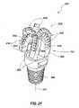
- FIG. 21shows a perspective view of a rotary drill bit including at least one superabrasive cutting element according to the present invention.
- FIG. 22shows a top elevation view of the rotary drill bit including at least one superabrasive cutting element according to the present invention as shown in FIG. 21 .
- the present inventionrelates generally to a superabrasive compact comprising a superabrasive layer or table bonded to a substrate. More specifically, a selected three-dimensional interface may be formed between the superabrasive layer and the substrate.
- the interfacemay comprise a depression formed into one end surface of the substrate. Such a depression may be formed over a majority of the end surface area and may form a closed peripheral wall extending proximate the periphery of the substrate.
- at least one raised featuremay extend from a base surface of the depression. In one embodiment, an upper surface of the at least one raised feature may extend beyond an upper surface of the closed peripheral wall.
- an exemplary superabrasive compact 120may be generally cylindrical about a central or longitudinal axis 111 .
- Superabrasive compact 120may comprise a superabrasive table 112 with an exposed surface 134 (e.g., a cutting face, if superabrasive compact 120 is employed as a cutting element) and an interfacial surface 132 , generally including complementary shaped protrusion 113 .
- Such a superabrasive compact 120may be able to withstand relatively high applied drilling forces because of a beneficial stress state and relatively high strength of mutual affixation between the superabrasive table 112 and substrate 110 provided by the interface 138 .
- a closed plane figuremay form a polygon.
- the dividing wallmay extend from the base surface and may separate two regions of the base surface.
- a lower surface surrounded by the dividing wallmay be uneven within (e.g. above or below) base surface 141 of depression 140 .
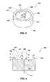
- FIG. 3shows a perspective view of one embodiment of a substrate 110 including an interfacial surface 130 comprising a depression 140 base surface 141 and a dividing wall 170 forming a generally square-shaped closed plane figure 180 .
- dividing wall 170may include a substantially planar upper surface 172 .
- upper surface 172may exhibit a nonplanar, selected topography.
- closed plane figure 180may include substantially cubic vertex regions 177 .
- dividing wall 170may taper (e.g, expand or shrink in relation to increasing distance from base surface 141 ), if desired.
- closed plane figure 180may exhibit a selected size.
- closed plane figure 180may be generally square-shaped and may have a side length of about 0.110 inches.
- closed plane figure 180may be generally rectangular, generally parallelogram, or generally polygonal, if desired.
- closed plane figure 180may exhibit a selected size. In one embodiment, closed plane figure 180 may exhibit an inner diameter of about 0.070 inches and an outer diameter of about 0.120 inches.
- any closed plane figure(e.g., a dividing wall following at least one curve, at least one linear path, or combinations of the foregoing, without limitation) as known in the art may be formed by a dividing wall.
- FIG. 5shows a perspective view of one embodiment of a substrate 110 including an interfacial surface 130 comprising a depression 140 forming base surface 141 as described above and a dividing wall 170 forming a generally triangular closed plane figure 180 .
- dividing wall 170may include a substantially planar upper surface 172 or, optionally, in other embodiments, upper surface 172 may exhibit a nonplanar, selected topography.
- a generally triangular closed plane figure 180may exhibit partially rounded vertex regions 177 , if desired, or may exhibit “sharp” vertex regions in other embodiments.
- dividing wall 170may taper (e.g., expand or shrink in relation to increasing distance from base surface 141 ), if desired.
- closed plane figure 180may exhibit a selected size.
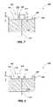
- FIG. 6shows a schematic, side cross-sectional view of a substrate 110 including a closed plane figure 180 .
- Closed plane figure 180may comprise any of the above-described embodiments, without limitation.
- upper surface 172 of closed plane figure 180may be positioned closer to base surface 141 than upper surface 152 of peripheral wall 150 .
- a magnitude of height or distance d 2 between base surface 141 and upper surface 172 of closed plane figure 180may be less than a magnitude of height or distance d between base surface 141 and upper surface 152 of peripheral wall 150 .
- peripheral wall 150may exhibit a selected thickness t. In one embodiment, thickness t may be about 0.015 inches to about 0.040 inches.
- closed plane figure 180may exhibit a selected thickness t 2 . In one embodiment, t 2 may be about 0.015 inches to about 0.040 inches
- an upper surface 172 of dividing wall 170may extend beyond upper surface 141 of peripheral wall 140 .
- FIG. 7shows a schematic, side cross-sectional view of a substrate 110 including a closed plane figure 180 .
- substrate 110may be as described above in relation to FIG. 6 .
- upper surface 172 of closed plane figure 180may be positioned farther from base surface 141 than upper surface 152 of peripheral wall 150 .
- a magnitude of height or distance d 2 between base surface 141 and upper surface 172 of closed plane figure 180may exceed a magnitude of height or distance d between base surface 141 and upper surface 152 of peripheral wall 150 .
- an upper surface 172 of dividing wall 170may be substantially even with upper surface 141 of peripheral wall 140 .
- FIG. 8shows a schematic, side cross-sectional view of a substrate 110 including a closed plane figure 180 .
- substrate 110may be as described above in relation to FIG. 6 .
- upper surface 172 of closed plane figure 180may be positioned at a distance from base surface 141 that is substantially equal to a distance between upper surface 152 of peripheral wall 150 and base surface 141 .
- a magnitude of height or distance d 2 between base surface 141 and upper surface 172 of closed plane figure 180may be substantially equal to a magnitude of height or distance d between base surface 141 and upper surface 152 of peripheral wall 150 .
- distances d and/or d 2may be between about 0.005 inches and about 0.250 inches.
- a raised featuremay be positioned within a depression formed into a substrate.
- a raised featuremay comprise a two leg sections.
- the two leg sections of the raised featuremay be substantially perpendicular to one another.
- FIG. 9shows a substrate 110 including an interfacial surface 130 comprising a peripheral wall 150 surrounding a depression 140 and a base surface 141 , generally as described above.
- a raised feature 200may be positioned generally within depression 140 . More specifically, in one embodiment, raised feature 200 may comprise a first leg section 202 and a second leg section 204 . As shown in FIG.
- each of leg sections 202 , 204may extend from a junction toward peripheral wall 150 .
- leg sections 202 , 204may be contiguous with (i.e., touching) peripheral wall 150 .
- leg sections 202 , 204may be adjacent to, but separated from, an inner surface 155 of peripheral wall 150 .
- the first leg section 202 and the second leg section 204may be generally perpendicular to one another.
- first leg section 202may extend generally along a first reference axis 201
- second leg section 204may extend generally along a second reference axis 203
- first reference axis 201is generally perpendicular to second reference axis 203 .
- a plurality of raised featuresmay be positioned generally within a depression formed into a substrate. More particularly, in one embodiment, a plurality of substantially identical raised features may be arranged in a selected configuration. For example, a plurality of substantially identical raised features may be positioned upon a selected reference path or shape about a central axis (e.g., along a reference circle or other shape) of a substrate.
- FIG. 10shows a perspective view of a substrate 110 including an interfacial surface 103 comprising a depression 140 and a plurality of raised features 200 (as described above in relation to FIG. 9 ) positioned in a circumferential pattern generally equidistantly from one another.
- each of the plurality of raised features 200may be positioned as if rotated about a selected axis (e.g., positioned at 0°, 90°, 180°, and 270°).
- a selected axismay be aligned with a longitudinal axis of the substrate 110 .
- Such a configurationmay, when a superabrasive table is bonded to the substrate 110 , promote regions of symmetry of residual stress fields in the substrate 110 , the superabrasive table, or both.
- a plurality of raised features 200may be arranged in any selected pattern or configuration, without limitation.
- a substratemay comprise a depression, a dividing wall forming a closed plane figure, and at least one raised feature extending from the base surface of the depression.
- FIG. 11shows a perspective view of one embodiment of a substrate 110 including an interface 130 comprising a peripheral wall 150 surrounding a depression 140 and base surface 141 .
- substrate 110includes a dividing wall 170 forming a generally square-shaped closed plane figure 180 (as described above with reference to FIGS. 1-3 and 6 - 8 ).
- a plurality of raised features 200are positioned between closed plane figure 180 and peripheral wall 150 .
- Such a configurationmay provide a desirable residual stress field when a superabrasive table is bonded to the interfacial surface 130 of substrate 110 .
- an upper surface 172 of dividing wall 170 forming a closed plane figure 180may be positioned below, above, or substantially even with an upper surface 152 of peripheral wall 150 .
- upper surface 172 of closed plane figure 180may be positioned closer to base surface 141 than upper surface 152 of peripheral wall 150 .
- a magnitude of distance between base surface 141 and upper surface 172 of closed plane figure 180may be less than a magnitude of distance between base surface 141 and upper surface 152 of peripheral wall 150 .
- upper surfaces 206 of raised features 200may be substantially even with an upper surface 172 of closed plane figure 180 .
- FIG. 12shows a perspective view of a substrate 110 including an interfacial surface 130 , wherein each of upper surfaces 206 of raised features 200 are positioned farther from base surface 141 than upper surface 152 of peripheral wall 150 .
- a magnitude of distance between base surface 141 each of upper surfaces 206 of raised features 200may be greater than a magnitude of distance between base surface 141 and upper surface 152 of peripheral wall 150 .
- an upper surface 172 of dividing wall 170 forming a closed plane figure 180may extend beyond an upper surface 152 of peripheral wall 150 . For example, as shown in FIG.
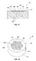
- FIG. 15shows a perspective view of one embodiment of a substrate 110 including a peripheral wall 150 .
- a plurality of elongated walls 220may extend across depression 140 .
- elongated channels 221may be positioned between adjacent elongated walls 220 .
- each of elongated walls 220may form a chord across peripheral wall 150 .
- an upper surface of each of elongated walls 220may be coplanar with upper surface 152 of peripheral wall 150 .
- an upper surface of each of elongated walls 220may be above or below upper surface 152 of peripheral wall 150 (i.e., a discontinuity or step may be formed between elongated walls 220 and peripheral wall 150 ).
- each of elongated walls 220may be substantially parallel to one another.
- one or more elongated wallsmay extend between different regions of peripheral wall 150 and may be nonparallel with one another or may intersect with one another, without limitation.
- a substratemay include a peripheral wall comprising a honeycomb structure.
- FIG. 18shows a substrate 110 including an interfacial surface 130 comprising a honeycomb structure 230 .
- honeycomb structure 230may comprise a peripheral hexagonal wall 234 , lower surfaces 233 , and a plurality of inner hexagonal walls 236 .
- peripheral hexagonal wall 234 , lower surfaces 233 , and a plurality of inner hexagonal walls 236may define hexagonal recesses 232 .
- lower surfaces 233 of hexagonal recesses 232are positioned below (i.e., into the substrate 110 ) or substantially even with (i.e., coplanar, in one embodiment) flange surface 153 .
- peripheral hexagonal wall 234may define a recess (i.e., collective lower surfaces 233 of hexagonal recesses 232 ), wherein inner hexagonal walls 236 separate the recess into hexagonal recesses 232 .
- a recessi.e., collective lower surfaces 233 of hexagonal recesses 232
- inner hexagonal walls 236separate the recess into hexagonal recesses 232 .
- any substrate known in the artmay be utilized, such as a substrate comprising at least one of the following materials: titanium carbide, niobium carbide, tantalum carbide, vanadium carbide, iron, and nickel, without limitation.
- a superabrasive compacte.g., polycrystalline diamond compact
- wire dies, bearings, artificial joints, cutting elements, and heat sinksmay include at least one superabrasive compact.
- the present inventioncontemplates that any of the embodiments encompassed by the above-discussion or variants encompassed thereby may be employed for forming a superabrasive compact.
- FIG. 20shows a superabrasive compact 120 including a superabrasive table 112 exhibiting exposed surface 134 , wherein the superabrasive table is bonded to a substrate 110 along interface 138 .
- superabrasive table 112may form a layer that at least partially (e.g. in one embodiment, completely) covers interfacial surface 130 of substrate 110 .
- interface 138may comprise a substrate interfacial surface (e.g., any substrate interfacial surface embodiment as discussed above in relation to FIGS.
- At least one of cutting elements 120may comprise a polycrystalline diamond table 112 formed upon a substrate 110 .
- rotary drill bit 301includes at least one cutting element 120
- the present inventionis not limited by such an example. Rather, a rotary drill bit according to the present invention may include, without limitation, one or more cutting elements according to the present invention.
- all of the cutting elements shown in FIGS. 21 and 22may exhibit at least one embodiment contemplated by the present invention.
- FIGS. 21 and 22merely depict one example of a rotary drill bit employing at least one cutting element 120 of the present invention, without limitation.
Landscapes
- Engineering & Computer Science (AREA)
- Life Sciences & Earth Sciences (AREA)
- Mining & Mineral Resources (AREA)
- Geology (AREA)
- Mechanical Engineering (AREA)
- Physics & Mathematics (AREA)
- Environmental & Geological Engineering (AREA)
- Fluid Mechanics (AREA)
- Chemical & Material Sciences (AREA)
- Crystallography & Structural Chemistry (AREA)
- General Life Sciences & Earth Sciences (AREA)
- Geochemistry & Mineralogy (AREA)
- Polishing Bodies And Polishing Tools (AREA)
- Processing Of Stones Or Stones Resemblance Materials (AREA)
Abstract
Description
Claims (32)
Priority Applications (2)
| Application Number | Priority Date | Filing Date | Title |
|---|---|---|---|
| US11/463,452US7493972B1 (en) | 2006-08-09 | 2006-08-09 | Superabrasive compact with selected interface and rotary drill bit including same |
| US12/368,896US7757790B1 (en) | 2006-08-09 | 2009-02-10 | Superabrasive compact with selected interface and rotary drill bit including same |
Applications Claiming Priority (1)
| Application Number | Priority Date | Filing Date | Title |
|---|---|---|---|
| US11/463,452US7493972B1 (en) | 2006-08-09 | 2006-08-09 | Superabrasive compact with selected interface and rotary drill bit including same |
Related Child Applications (1)
| Application Number | Title | Priority Date | Filing Date |
|---|---|---|---|
| US12/368,896ContinuationUS7757790B1 (en) | 2006-08-09 | 2009-02-10 | Superabrasive compact with selected interface and rotary drill bit including same |
Publications (1)
| Publication Number | Publication Date |
|---|---|
| US7493972B1true US7493972B1 (en) | 2009-02-24 |
Family
ID=40364537
Family Applications (2)
| Application Number | Title | Priority Date | Filing Date |
|---|---|---|---|
| US11/463,452Expired - Fee RelatedUS7493972B1 (en) | 2006-08-09 | 2006-08-09 | Superabrasive compact with selected interface and rotary drill bit including same |
| US12/368,896Expired - Fee RelatedUS7757790B1 (en) | 2006-08-09 | 2009-02-10 | Superabrasive compact with selected interface and rotary drill bit including same |
Family Applications After (1)
| Application Number | Title | Priority Date | Filing Date |
|---|---|---|---|
| US12/368,896Expired - Fee RelatedUS7757790B1 (en) | 2006-08-09 | 2009-02-10 | Superabrasive compact with selected interface and rotary drill bit including same |
Country Status (1)
| Country | Link |
|---|---|
| US (2) | US7493972B1 (en) |
Cited By (23)
| Publication number | Priority date | Publication date | Assignee | Title |
|---|---|---|---|---|
| US20100084198A1 (en)* | 2008-10-08 | 2010-04-08 | Smith International, Inc. | Cutters for fixed cutter bits |
| US20100084196A1 (en)* | 2008-10-03 | 2010-04-08 | Us Synthetic Corporation | Polycrystalline diamond, polycrystalline diamond compact, method of fabricating same, and various applications |
| US7757790B1 (en)* | 2006-08-09 | 2010-07-20 | Us Synthetic Corporation | Superabrasive compact with selected interface and rotary drill bit including same |
| US20110017519A1 (en)* | 2008-10-03 | 2011-01-27 | Us Synthetic Corporation | Polycrystalline diamond compacts, method of fabricating same, and various applications |
| US20110120782A1 (en)* | 2009-11-25 | 2011-05-26 | Us Synthetic Corporation | Polycrystalline diamond compact including a substrate having a raised interfacial surface bonded to a leached polycrystalline diamond table, and applications therefor |
| US20120103699A1 (en)* | 2010-10-28 | 2012-05-03 | Smith International, Inc. | Interface design of tsp shear cutters |
| US8727046B2 (en) | 2011-04-15 | 2014-05-20 | Us Synthetic Corporation | Polycrystalline diamond compacts including at least one transition layer and methods for stress management in polycrsystalline diamond compacts |
| US20140238753A1 (en)* | 2013-02-28 | 2014-08-28 | Baker Hughes Incorporated | Cutting elements including non-planar interfaces, earth-boring tools including such cutting elements, and methods of forming cutting elements |
| US8820442B2 (en) | 2010-03-02 | 2014-09-02 | Us Synthetic Corporation | Polycrystalline diamond compact including a substrate having a raised interfacial surface bonded to a polycrystalline diamond table, and applications therefor |
| WO2015091672A3 (en)* | 2013-12-17 | 2015-11-19 | Element Six Limited | Superhard constructions & methods of making same |
| US9199356B2 (en) | 2010-12-22 | 2015-12-01 | Element Six Abrasives S.A. | Cutting element |
| US9315881B2 (en) | 2008-10-03 | 2016-04-19 | Us Synthetic Corporation | Polycrystalline diamond, polycrystalline diamond compacts, methods of making same, and applications |
| US9376867B2 (en) | 2011-09-16 | 2016-06-28 | Baker Hughes Incorporated | Methods of drilling a subterranean bore hole |
| EP2585669A4 (en)* | 2010-06-24 | 2016-08-10 | Baker Hughes Inc | Cutting elements for earth-boring tools, earth-boring tools including such cutting elements, and methods of forming cutting elements for earth-boring tools |
| US9428966B2 (en) | 2012-05-01 | 2016-08-30 | Baker Hughes Incorporated | Cutting elements for earth-boring tools, earth-boring tools including such cutting elements, and related methods |
| US9821437B2 (en) | 2012-05-01 | 2017-11-21 | Baker Hughes Incorporated | Earth-boring tools having cutting elements with cutting faces exhibiting multiple coefficients of friction, and related methods |
| US20180230754A1 (en)* | 2017-02-16 | 2018-08-16 | Baker Hughes Incorporated | Cutting tables including rhenium-containing structures, and related cutting elements, earth-boring tools, and methods |
| EP3341623A4 (en)* | 2015-08-26 | 2019-01-16 | US Synthetic Corporation | OSCILLATING SKATE BEARING ASSEMBLIES, AND BEARING APPARATUSES AND METHODS FOR THEIR USE |
| US10208794B2 (en)* | 2015-08-10 | 2019-02-19 | Dalian Sanhuan Composite Material Technology Development Co., Ltd. | Water lubricated composite thrust bearing of nuclear main pump |
| US10337255B2 (en) | 2011-04-22 | 2019-07-02 | Baker Hughes Incorporated | Cutting elements for earth-boring tools, earth-boring tools including such cutting elements, and related methods |
| US10428591B2 (en) | 2011-04-22 | 2019-10-01 | Baker Hughes Incorporated | Structures for drilling a subterranean formation |
| US10711331B2 (en) | 2015-04-28 | 2020-07-14 | Halliburton Energy Services, Inc. | Polycrystalline diamond compact with gradient interfacial layer |
| US11649682B1 (en)* | 2016-08-26 | 2023-05-16 | Us Synthetic Corporation | Multi-part superabrasive compacts, rotary drill bits including multi-part superabrasive compacts, and related methods |
Families Citing this family (2)
| Publication number | Priority date | Publication date | Assignee | Title |
|---|---|---|---|---|
| US10060192B1 (en)* | 2014-08-14 | 2018-08-28 | Us Synthetic Corporation | Methods of making polycrystalline diamond compacts and polycrystalline diamond compacts made using the same |
| WO2025186438A1 (en)* | 2024-03-08 | 2025-09-12 | Element Six Gmbh | Insert |
Citations (18)
| Publication number | Priority date | Publication date | Assignee | Title |
|---|---|---|---|---|
| US4764434A (en) | 1987-06-26 | 1988-08-16 | Sandvik Aktiebolag | Diamond tools for rock drilling and machining |
| US4997049A (en) | 1988-08-15 | 1991-03-05 | Klaus Tank | Tool insert |
| US5120327A (en) | 1991-03-05 | 1992-06-09 | Diamant-Boart Stratabit (Usa) Inc. | Cutting composite formed of cemented carbide substrate and diamond layer |
| US5355969A (en)* | 1993-03-22 | 1994-10-18 | U.S. Synthetic Corporation | Composite polycrystalline cutting element with improved fracture and delamination resistance |
| US5379854A (en) | 1993-08-17 | 1995-01-10 | Dennis Tool Company | Cutting element for drill bits |
| US5435403A (en) | 1993-12-09 | 1995-07-25 | Baker Hughes Incorporated | Cutting elements with enhanced stiffness and arrangements thereof on earth boring drill bits |
| US5472376A (en) | 1992-12-23 | 1995-12-05 | Olmstead; Bruce R. | Tool component |
| US5484330A (en) | 1993-07-21 | 1996-01-16 | General Electric Company | Abrasive tool insert |
| US5590728A (en) | 1993-11-10 | 1997-01-07 | Camco Drilling Group Limited | Elements faced with superhard material |
| US5711702A (en) | 1996-08-27 | 1998-01-27 | Tempo Technology Corporation | Curve cutter with non-planar interface |
| US5875862A (en)* | 1995-07-14 | 1999-03-02 | U.S. Synthetic Corporation | Polycrystalline diamond cutter with integral carbide/diamond transition layer |
| US5906246A (en) | 1996-06-13 | 1999-05-25 | Smith International, Inc. | PDC cutter element having improved substrate configuration |
| US6041875A (en) | 1996-12-06 | 2000-03-28 | Smith International, Inc. | Non-planar interfaces for cutting elements |
| US6068071A (en) | 1996-05-23 | 2000-05-30 | U.S. Synthetic Corporation | Cutter with polycrystalline diamond layer and conic section profile |
| US6488106B1 (en)* | 2001-02-05 | 2002-12-03 | Varel International, Inc. | Superabrasive cutting element |
| US6571891B1 (en)* | 1996-04-17 | 2003-06-03 | Baker Hughes Incorporated | Web cutter |
| US6962218B2 (en)* | 2003-06-03 | 2005-11-08 | Smith International, Inc. | Cutting elements with improved cutting element interface design and bits incorporating the same |
| US7270199B2 (en)* | 2005-09-19 | 2007-09-18 | Hall David R | Cutting element with a non-shear stress relieving substrate interface |
Family Cites Families (1)
| Publication number | Priority date | Publication date | Assignee | Title |
|---|---|---|---|---|
| US7493972B1 (en)* | 2006-08-09 | 2009-02-24 | Us Synthetic Corporation | Superabrasive compact with selected interface and rotary drill bit including same |
- 2006
- 2006-08-09USUS11/463,452patent/US7493972B1/ennot_activeExpired - Fee Related
- 2009
- 2009-02-10USUS12/368,896patent/US7757790B1/ennot_activeExpired - Fee Related
Patent Citations (19)
| Publication number | Priority date | Publication date | Assignee | Title |
|---|---|---|---|---|
| US4764434A (en) | 1987-06-26 | 1988-08-16 | Sandvik Aktiebolag | Diamond tools for rock drilling and machining |
| US4997049A (en) | 1988-08-15 | 1991-03-05 | Klaus Tank | Tool insert |
| US5120327A (en) | 1991-03-05 | 1992-06-09 | Diamant-Boart Stratabit (Usa) Inc. | Cutting composite formed of cemented carbide substrate and diamond layer |
| US5472376A (en) | 1992-12-23 | 1995-12-05 | Olmstead; Bruce R. | Tool component |
| US5355969A (en)* | 1993-03-22 | 1994-10-18 | U.S. Synthetic Corporation | Composite polycrystalline cutting element with improved fracture and delamination resistance |
| US5484330A (en) | 1993-07-21 | 1996-01-16 | General Electric Company | Abrasive tool insert |
| US5379854A (en) | 1993-08-17 | 1995-01-10 | Dennis Tool Company | Cutting element for drill bits |
| US5590728A (en) | 1993-11-10 | 1997-01-07 | Camco Drilling Group Limited | Elements faced with superhard material |
| US5435403A (en) | 1993-12-09 | 1995-07-25 | Baker Hughes Incorporated | Cutting elements with enhanced stiffness and arrangements thereof on earth boring drill bits |
| US5875862A (en)* | 1995-07-14 | 1999-03-02 | U.S. Synthetic Corporation | Polycrystalline diamond cutter with integral carbide/diamond transition layer |
| US6571891B1 (en)* | 1996-04-17 | 2003-06-03 | Baker Hughes Incorporated | Web cutter |
| US6068071A (en) | 1996-05-23 | 2000-05-30 | U.S. Synthetic Corporation | Cutter with polycrystalline diamond layer and conic section profile |
| US5906246A (en) | 1996-06-13 | 1999-05-25 | Smith International, Inc. | PDC cutter element having improved substrate configuration |
| US5711702A (en) | 1996-08-27 | 1998-01-27 | Tempo Technology Corporation | Curve cutter with non-planar interface |
| US6041875A (en) | 1996-12-06 | 2000-03-28 | Smith International, Inc. | Non-planar interfaces for cutting elements |
| US6739417B2 (en)* | 1998-12-22 | 2004-05-25 | Baker Hughes Incorporated | Superabrasive cutters and drill bits so equipped |
| US6488106B1 (en)* | 2001-02-05 | 2002-12-03 | Varel International, Inc. | Superabrasive cutting element |
| US6962218B2 (en)* | 2003-06-03 | 2005-11-08 | Smith International, Inc. | Cutting elements with improved cutting element interface design and bits incorporating the same |
| US7270199B2 (en)* | 2005-09-19 | 2007-09-18 | Hall David R | Cutting element with a non-shear stress relieving substrate interface |
Cited By (67)
| Publication number | Priority date | Publication date | Assignee | Title |
|---|---|---|---|---|
| US7757790B1 (en)* | 2006-08-09 | 2010-07-20 | Us Synthetic Corporation | Superabrasive compact with selected interface and rotary drill bit including same |
| US10961785B2 (en) | 2008-10-03 | 2021-03-30 | Us Synthetic Corporation | Polycrystalline diamond compact |
| US10508502B2 (en) | 2008-10-03 | 2019-12-17 | Us Synthetic Corporation | Polycrystalline diamond compact |
| US20100225311A1 (en)* | 2008-10-03 | 2010-09-09 | Us Synthetic Corporation | Method of characterizing a polycrystalline diamond element by at least one magnetic measurement |
| US20100307069A1 (en)* | 2008-10-03 | 2010-12-09 | Us Synthetic Corporation | Polycrystalline diamond compact |
| US20100310855A1 (en)* | 2008-10-03 | 2010-12-09 | Us Synthetic Corporation | Polycrystalline diamond |
| US7866418B2 (en) | 2008-10-03 | 2011-01-11 | Us Synthetic Corporation | Rotary drill bit including polycrystalline diamond cutting elements |
| US20110017519A1 (en)* | 2008-10-03 | 2011-01-27 | Us Synthetic Corporation | Polycrystalline diamond compacts, method of fabricating same, and various applications |
| US9315881B2 (en) | 2008-10-03 | 2016-04-19 | Us Synthetic Corporation | Polycrystalline diamond, polycrystalline diamond compacts, methods of making same, and applications |
| US8020645B2 (en) | 2008-10-03 | 2011-09-20 | Us Synthetic Corporation | Method of fabricating polycrystalline diamond and a polycrystalline diamond compact |
| US8158258B2 (en) | 2008-10-03 | 2012-04-17 | Us Synthetic Corporation | Polycrystalline diamond |
| US9932274B2 (en) | 2008-10-03 | 2018-04-03 | Us Synthetic Corporation | Polycrystalline diamond compacts |
| US10507565B2 (en) | 2008-10-03 | 2019-12-17 | Us Synthetic Corporation | Polycrystalline diamond, polycrystalline diamond compacts, methods of making same, and applications |
| US8297382B2 (en) | 2008-10-03 | 2012-10-30 | Us Synthetic Corporation | Polycrystalline diamond compacts, method of fabricating same, and various applications |
| US10287822B2 (en) | 2008-10-03 | 2019-05-14 | Us Synthetic Corporation | Methods of fabricating a polycrystalline diamond compact |
| US8461832B2 (en) | 2008-10-03 | 2013-06-11 | Us Synthetic Corporation | Method of characterizing a polycrystalline diamond element by at least one magnetic measurement |
| US8766628B2 (en) | 2008-10-03 | 2014-07-01 | Us Synthetic Corporation | Methods of characterizing a component of a polycrystalline diamond compact by at least one magnetic measurement |
| US10703681B2 (en) | 2008-10-03 | 2020-07-07 | Us Synthetic Corporation | Polycrystalline diamond compacts |
| US12350792B2 (en) | 2008-10-03 | 2025-07-08 | Us Synthetic Corporation | Polycrystalline diamond, polycrystalline diamond compacts, methods of making same, and applications |
| US12044075B2 (en) | 2008-10-03 | 2024-07-23 | Us Synthetic Corporation | Polycrystalline diamond compact |
| US9459236B2 (en) | 2008-10-03 | 2016-10-04 | Us Synthetic Corporation | Polycrystalline diamond compact |
| US20100084196A1 (en)* | 2008-10-03 | 2010-04-08 | Us Synthetic Corporation | Polycrystalline diamond, polycrystalline diamond compact, method of fabricating same, and various applications |
| US12297153B2 (en) | 2008-10-03 | 2025-05-13 | Us Synthetic Corporation | Polycrystalline diamond compacts |
| US8616306B2 (en) | 2008-10-03 | 2013-12-31 | Us Synthetic Corporation | Polycrystalline diamond compacts, method of fabricating same, and various applications |
| US9134275B2 (en) | 2008-10-03 | 2015-09-15 | Us Synthetic Corporation | Polycrystalline diamond compact and method of fabricating same |
| US8833492B2 (en)* | 2008-10-08 | 2014-09-16 | Smith International, Inc. | Cutters for fixed cutter bits |
| US20100084198A1 (en)* | 2008-10-08 | 2010-04-08 | Smith International, Inc. | Cutters for fixed cutter bits |
| US8689913B2 (en) | 2009-11-25 | 2014-04-08 | Us Synthetic Corporation | Polycrystalline diamond compact including a substrate having a raised interfacial surface bonded to a leached polycrystalline diamond table, and applications therefor |
| US8353371B2 (en) | 2009-11-25 | 2013-01-15 | Us Synthetic Corporation | Polycrystalline diamond compact including a substrate having a raised interfacial surface bonded to a leached polycrystalline diamond table, and applications therefor |
| US20110120782A1 (en)* | 2009-11-25 | 2011-05-26 | Us Synthetic Corporation | Polycrystalline diamond compact including a substrate having a raised interfacial surface bonded to a leached polycrystalline diamond table, and applications therefor |
| US9435160B2 (en) | 2010-03-02 | 2016-09-06 | Us Synthetic Corporation | Polycrystalline diamond compact including a substrate having a raised interfacial surface bonded to a polycrystalline diamond table, and applications therefor |
| US8820442B2 (en) | 2010-03-02 | 2014-09-02 | Us Synthetic Corporation | Polycrystalline diamond compact including a substrate having a raised interfacial surface bonded to a polycrystalline diamond table, and applications therefor |
| EP2585669A4 (en)* | 2010-06-24 | 2016-08-10 | Baker Hughes Inc | Cutting elements for earth-boring tools, earth-boring tools including such cutting elements, and methods of forming cutting elements for earth-boring tools |
| US9931736B2 (en) | 2010-06-24 | 2018-04-03 | Baker Hughes Incorporated | Cutting elements for earth-boring tools, earth-boring tools including such cutting elements, and methods of forming cutting elements for earth-boring tools |
| US8899358B2 (en)* | 2010-10-28 | 2014-12-02 | Smith International, Inc. | Interface design of TSP shear cutters |
| GB2500508A (en)* | 2010-10-28 | 2013-09-25 | Smith International | Interface design of tsp shear cutters |
| CN103237952A (en)* | 2010-10-28 | 2013-08-07 | 史密斯运输股份有限公司 | Interface design of TSP shear cutters |
| WO2012058562A3 (en)* | 2010-10-28 | 2012-06-28 | Smith International, Inc. | Interface design of tsp shear cutters |
| US20120103699A1 (en)* | 2010-10-28 | 2012-05-03 | Smith International, Inc. | Interface design of tsp shear cutters |
| US9199356B2 (en) | 2010-12-22 | 2015-12-01 | Element Six Abrasives S.A. | Cutting element |
| US8727046B2 (en) | 2011-04-15 | 2014-05-20 | Us Synthetic Corporation | Polycrystalline diamond compacts including at least one transition layer and methods for stress management in polycrsystalline diamond compacts |
| US10350730B2 (en) | 2011-04-15 | 2019-07-16 | Us Synthetic Corporation | Polycrystalline diamond compacts including at least one transition layer and methods for stress management in polycrystalline diamond compacts |
| US10428591B2 (en) | 2011-04-22 | 2019-10-01 | Baker Hughes Incorporated | Structures for drilling a subterranean formation |
| US10337255B2 (en) | 2011-04-22 | 2019-07-02 | Baker Hughes Incorporated | Cutting elements for earth-boring tools, earth-boring tools including such cutting elements, and related methods |
| US9376867B2 (en) | 2011-09-16 | 2016-06-28 | Baker Hughes Incorporated | Methods of drilling a subterranean bore hole |
| US10385623B2 (en) | 2011-09-16 | 2019-08-20 | Baker Hughes, A Ge Company, Llc | Cutting elements for earth-boring tools and earth-boring tools including such cutting elements |
| US10428590B2 (en) | 2011-09-16 | 2019-10-01 | Baker Hughes, A Ge Company, Llc | Cutting elements for earth-boring tools and earth-boring tools including such cutting elements |
| US11229989B2 (en) | 2012-05-01 | 2022-01-25 | Baker Hughes Holdings Llc | Methods of forming cutting elements with cutting faces exhibiting multiple coefficients of friction, and related methods |
| US10066442B2 (en) | 2012-05-01 | 2018-09-04 | Baker Hughes Incorporated | Cutting elements for earth-boring tools, earth-boring tools including such cutting elements, and related methods |
| US9428966B2 (en) | 2012-05-01 | 2016-08-30 | Baker Hughes Incorporated | Cutting elements for earth-boring tools, earth-boring tools including such cutting elements, and related methods |
| US9821437B2 (en) | 2012-05-01 | 2017-11-21 | Baker Hughes Incorporated | Earth-boring tools having cutting elements with cutting faces exhibiting multiple coefficients of friction, and related methods |
| US9140072B2 (en)* | 2013-02-28 | 2015-09-22 | Baker Hughes Incorporated | Cutting elements including non-planar interfaces, earth-boring tools including such cutting elements, and methods of forming cutting elements |
| US20140238753A1 (en)* | 2013-02-28 | 2014-08-28 | Baker Hughes Incorporated | Cutting elements including non-planar interfaces, earth-boring tools including such cutting elements, and methods of forming cutting elements |
| CN106068362A (en)* | 2013-12-17 | 2016-11-02 | 第六元素有限公司 | Superhard component and manufacture method thereof |
| US20160311689A1 (en)* | 2013-12-17 | 2016-10-27 | Element Six Limited | Superhard constructions & methods of making same |
| WO2015091672A3 (en)* | 2013-12-17 | 2015-11-19 | Element Six Limited | Superhard constructions & methods of making same |
| US20220144646A1 (en)* | 2013-12-17 | 2022-05-12 | Element Six Limited | Superhard constructions & methods of making same |
| US10711331B2 (en) | 2015-04-28 | 2020-07-14 | Halliburton Energy Services, Inc. | Polycrystalline diamond compact with gradient interfacial layer |
| US10208794B2 (en)* | 2015-08-10 | 2019-02-19 | Dalian Sanhuan Composite Material Technology Development Co., Ltd. | Water lubricated composite thrust bearing of nuclear main pump |
| US10753388B2 (en) | 2015-08-26 | 2020-08-25 | Us Synthetic Corporation | Tilting pad bearing assemblies, and bearing apparatuses and methods of using the same |
| US11085488B2 (en) | 2015-08-26 | 2021-08-10 | Us Synthetic Corporation | Tilting pad bearing assemblies, and bearing apparatuses and methods of using the same |
| EP3341623A4 (en)* | 2015-08-26 | 2019-01-16 | US Synthetic Corporation | OSCILLATING SKATE BEARING ASSEMBLIES, AND BEARING APPARATUSES AND METHODS FOR THEIR USE |
| US11649682B1 (en)* | 2016-08-26 | 2023-05-16 | Us Synthetic Corporation | Multi-part superabrasive compacts, rotary drill bits including multi-part superabrasive compacts, and related methods |
| US20180230754A1 (en)* | 2017-02-16 | 2018-08-16 | Baker Hughes Incorporated | Cutting tables including rhenium-containing structures, and related cutting elements, earth-boring tools, and methods |
| CN110494624B (en)* | 2017-02-16 | 2021-09-07 | 通用电气(Ge)贝克休斯有限责任公司 | Cutting table including rhenium-containing structures, and related cutting elements, earth-boring tools, and methods |
| US10619422B2 (en)* | 2017-02-16 | 2020-04-14 | Baker Hughes, A Ge Company, Llc | Cutting tables including rhenium-containing structures, and related cutting elements, earth-boring tools, and methods |
| CN110494624A (en)* | 2017-02-16 | 2019-11-22 | 通用电气(Ge)贝克休斯有限责任公司 | Cutting table and related cutting element, earth-boring tools and method including rhenium-containing structure |
Also Published As
| Publication number | Publication date |
|---|---|
| US7757790B1 (en) | 2010-07-20 |
Similar Documents
| Publication | Publication Date | Title |
|---|---|---|
| US7493972B1 (en) | Superabrasive compact with selected interface and rotary drill bit including same | |
| US10920499B1 (en) | Polycrystalline diamond compact including a non-uniformly leached polycrystalline diamond table and applications therefor | |
| US10428585B2 (en) | Methods of fabricating cutting elements for earth-boring tools and methods of selectively removing a portion of a cutting element of an earth-boring tool | |
| US11459830B2 (en) | Devices and systems for using additive manufacturing to manufacture a tool crown | |
| US9435160B2 (en) | Polycrystalline diamond compact including a substrate having a raised interfacial surface bonded to a polycrystalline diamond table, and applications therefor | |
| US8353371B2 (en) | Polycrystalline diamond compact including a substrate having a raised interfacial surface bonded to a leached polycrystalline diamond table, and applications therefor | |
| US8783388B1 (en) | Superabrasive inserts including an arcuate peripheral surface | |
| US9163461B2 (en) | Methods of attaching a shank to a body of an earth-boring tool including a load-bearing joint and tools formed by such methods | |
| CA2942530C (en) | Cutting elements having non-planar cutting faces with selectively leached regions, earth-boring tools including such cutting elements, and related methods | |
| US9605488B2 (en) | Cutting elements including undulating boundaries between catalyst-containing and catalyst-free regions of polycrystalline superabrasive materials and related earth-boring tools and methods | |
| US10024113B2 (en) | Cutting elements having a non-uniform annulus leach depth, earth-boring tools including such cutting elements, and related methods | |
| US11719050B2 (en) | Cutting elements for earth-boring tools and related earth-boring tools and methods |
Legal Events
| Date | Code | Title | Description |
|---|---|---|---|
| AS | Assignment | Owner name:US SYNTHETIC CORPORATION, UTAH Free format text:ASSIGNMENT OF ASSIGNORS INTEREST;ASSIGNOR:SCHMIDT, SCOTT M.;REEL/FRAME:018079/0561 Effective date:20060808 | |
| AS | Assignment | Owner name:U.S. SYNTHETIC CORPORATION, UTAH Free format text:ASSIGNMENT OF ASSIGNORS INTEREST;ASSIGNORS:SCHMIDT, SCOTT M.;SANDSTROM, MICHAEL JOHN;REEL/FRAME:018717/0156;SIGNING DATES FROM 20061211 TO 20061212 | |
| STCF | Information on status: patent grant | Free format text:PATENTED CASE | |
| FPAY | Fee payment | Year of fee payment:4 | |
| FEPP | Fee payment procedure | Free format text:PAYOR NUMBER ASSIGNED (ORIGINAL EVENT CODE: ASPN); ENTITY STATUS OF PATENT OWNER: LARGE ENTITY | |
| FPAY | Fee payment | Year of fee payment:8 | |
| AS | Assignment | Owner name:JPMORGAN CHASE BANK, N.A., NEW YORK Free format text:SECURITY AGREEMENT;ASSIGNORS:APERGY (DELAWARE) FORMATION, INC.;APERGY BMCS ACQUISITION CORP.;APERGY ENERGY AUTOMATION, LLC;AND OTHERS;REEL/FRAME:046117/0015 Effective date:20180509 | |
| AS | Assignment | Owner name:BANK OF AMERICA, N.A., NORTH CAROLINA Free format text:SECURITY INTEREST;ASSIGNORS:ACE DOWNHOLE, LLC;APERGY BMCS ACQUISITION CORP.;HARBISON-FISCHER, INC.;AND OTHERS;REEL/FRAME:053790/0001 Effective date:20200603 | |
| FEPP | Fee payment procedure | Free format text:MAINTENANCE FEE REMINDER MAILED (ORIGINAL EVENT CODE: REM.); ENTITY STATUS OF PATENT OWNER: LARGE ENTITY | |
| LAPS | Lapse for failure to pay maintenance fees | Free format text:PATENT EXPIRED FOR FAILURE TO PAY MAINTENANCE FEES (ORIGINAL EVENT CODE: EXP.); ENTITY STATUS OF PATENT OWNER: LARGE ENTITY | |
| STCH | Information on status: patent discontinuation | Free format text:PATENT EXPIRED DUE TO NONPAYMENT OF MAINTENANCE FEES UNDER 37 CFR 1.362 | |
| FP | Lapsed due to failure to pay maintenance fee | Effective date:20210224 | |
| AS | Assignment | Owner name:WINDROCK, INC., TEXAS Free format text:RELEASE BY SECURED PARTY;ASSIGNOR:BANK OF AMERICA, N.A.;REEL/FRAME:060305/0001 Effective date:20220607 Owner name:US SYNTHETIC CORPORATION, TEXAS Free format text:RELEASE BY SECURED PARTY;ASSIGNOR:BANK OF AMERICA, N.A.;REEL/FRAME:060305/0001 Effective date:20220607 Owner name:NORRISEAL-WELLMARK, INC., TEXAS Free format text:RELEASE BY SECURED PARTY;ASSIGNOR:BANK OF AMERICA, N.A.;REEL/FRAME:060305/0001 Effective date:20220607 Owner name:APERGY BMCS ACQUISITION CORP., TEXAS Free format text:RELEASE BY SECURED PARTY;ASSIGNOR:BANK OF AMERICA, N.A.;REEL/FRAME:060305/0001 Effective date:20220607 Owner name:THETA OILFIELD SERVICES, INC., TEXAS Free format text:RELEASE BY SECURED PARTY;ASSIGNOR:BANK OF AMERICA, N.A.;REEL/FRAME:060305/0001 Effective date:20220607 Owner name:SPIRIT GLOBAL ENERGY SOLUTIONS, INC., TEXAS Free format text:RELEASE BY SECURED PARTY;ASSIGNOR:BANK OF AMERICA, N.A.;REEL/FRAME:060305/0001 Effective date:20220607 Owner name:QUARTZDYNE, INC., TEXAS Free format text:RELEASE BY SECURED PARTY;ASSIGNOR:BANK OF AMERICA, N.A.;REEL/FRAME:060305/0001 Effective date:20220607 Owner name:PCS FERGUSON, INC., TEXAS Free format text:RELEASE BY SECURED PARTY;ASSIGNOR:BANK OF AMERICA, N.A.;REEL/FRAME:060305/0001 Effective date:20220607 Owner name:NORRIS RODS, INC., TEXAS Free format text:RELEASE BY SECURED PARTY;ASSIGNOR:BANK OF AMERICA, N.A.;REEL/FRAME:060305/0001 Effective date:20220607 Owner name:HARBISON-FISCHER, INC., TEXAS Free format text:RELEASE BY SECURED PARTY;ASSIGNOR:BANK OF AMERICA, N.A.;REEL/FRAME:060305/0001 Effective date:20220607 Owner name:ACE DOWNHOLE, LLC, TEXAS Free format text:RELEASE BY SECURED PARTY;ASSIGNOR:BANK OF AMERICA, N.A.;REEL/FRAME:060305/0001 Effective date:20220607 | |
| AS | Assignment | Owner name:CHAMPIONX LLC, TEXAS Free format text:RELEASE OF SECURITY INTEREST IN PATENTS;ASSIGNOR:JPMORGAN CHASE BANK, N.A.;REEL/FRAME:072004/0019 Effective date:20250716 Owner name:APERGY ESP SYSTEMS, LLC, TEXAS Free format text:RELEASE OF SECURITY INTEREST IN PATENTS;ASSIGNOR:JPMORGAN CHASE BANK, N.A.;REEL/FRAME:072004/0019 Effective date:20250716 Owner name:APERGY BMCS ACQUISITION CORP, TEXAS Free format text:RELEASE OF SECURITY INTEREST IN PATENTS;ASSIGNOR:JPMORGAN CHASE BANK, N.A.;REEL/FRAME:072004/0019 Effective date:20250716 Owner name:HARBISON-FISCHER, INC., TEXAS Free format text:RELEASE OF SECURITY INTEREST IN PATENTS;ASSIGNOR:JPMORGAN CHASE BANK, N.A.;REEL/FRAME:072004/0019 Effective date:20250716 Owner name:NORRIS RODS, INC.,, TEXAS Free format text:RELEASE OF SECURITY INTEREST IN PATENTS;ASSIGNOR:JPMORGAN CHASE BANK, N.A.;REEL/FRAME:072004/0019 Effective date:20250716 Owner name:NORRISEAL-WELLMARK, INC., TEXAS Free format text:RELEASE OF SECURITY INTEREST IN PATENTS;ASSIGNOR:JPMORGAN CHASE BANK, N.A.;REEL/FRAME:072004/0019 Effective date:20250716 Owner name:PCS FERGUSON, INC., TEXAS Free format text:RELEASE OF SECURITY INTEREST IN PATENTS;ASSIGNOR:JPMORGAN CHASE BANK, N.A.;REEL/FRAME:072004/0019 Effective date:20250716 Owner name:QUARTZDYNE, INC., TEXAS Free format text:RELEASE OF SECURITY INTEREST IN PATENTS;ASSIGNOR:JPMORGAN CHASE BANK, N.A.;REEL/FRAME:072004/0019 Effective date:20250716 Owner name:US SYNTHETIC CORPORATION, TEXAS Free format text:RELEASE OF SECURITY INTEREST IN PATENTS;ASSIGNOR:JPMORGAN CHASE BANK, N.A.;REEL/FRAME:072004/0019 Effective date:20250716 |