US7493005B2 - Coupler for cable trough - Google Patents
Coupler for cable troughDownload PDFInfo
- Publication number
- US7493005B2 US7493005B2US11/677,184US67718407AUS7493005B2US 7493005 B2US7493005 B2US 7493005B2US 67718407 AUS67718407 AUS 67718407AUS 7493005 B2US7493005 B2US 7493005B2
- Authority
- US
- United States
- Prior art keywords
- clip
- slot
- coupler
- trough
- trough member
- Prior art date
- Legal status (The legal status is an assumption and is not a legal conclusion. Google has not performed a legal analysis and makes no representation as to the accuracy of the status listed.)
- Active
Links
Images


Classifications
- G—PHYSICS
- G02—OPTICS
- G02B—OPTICAL ELEMENTS, SYSTEMS OR APPARATUS
- G02B6/00—Light guides; Structural details of arrangements comprising light guides and other optical elements, e.g. couplings
- G02B6/44—Mechanical structures for providing tensile strength and external protection for fibres, e.g. optical transmission cables
- G02B6/4439—Auxiliary devices
- G02B6/4459—Ducts; Conduits; Hollow tubes for air blown fibres
- Y—GENERAL TAGGING OF NEW TECHNOLOGICAL DEVELOPMENTS; GENERAL TAGGING OF CROSS-SECTIONAL TECHNOLOGIES SPANNING OVER SEVERAL SECTIONS OF THE IPC; TECHNICAL SUBJECTS COVERED BY FORMER USPC CROSS-REFERENCE ART COLLECTIONS [XRACs] AND DIGESTS
- Y10—TECHNICAL SUBJECTS COVERED BY FORMER USPC
- Y10T—TECHNICAL SUBJECTS COVERED BY FORMER US CLASSIFICATION
- Y10T403/00—Joints and connections
- Y10T403/55—Member ends joined by inserted section
- Y10T403/551—Externally bridged
Definitions
- Embodiments disclosed hereinrelate to systems for the management and routing of telecommunication cables, and, more particularly, to couplers for joining trough members.
- optical fiber systemsare increasingly used for high-speed signal transmission.
- optical fiber cable managementrequires industry attention.
- optical fiber managementis the routing of optical fibers from one piece of equipment to another.
- optical fiber cablesare routed between fiber distribution equipment and optical line terminating equipment.
- the cable routingtypically takes place in concealed ceiling areas or in other manners to route cables from one location to another.
- routing systemsWhen routing optical fibers and other cables such as copper wires, it is desirable that a routing system is readily modifiable and adaptable to changes in equipment needs. Accordingly, such routing systems include a plurality of components, such as trough members and couplers, for defining the cable routing paths. The trough members are joined together by couplings.
- U.S. Pat. Nos. 5,067,678; 5,316,243; 5,752,781; 6,709,186; and 6,715,719teach cable routing systems that include a plurality of trough members and couplers.
- couplersfor coupling trough members.
- One concernis that a plurality of hardware is used for joining the trough members. This hardware can be cumbersome. Further, there is sometimes a need to rearrange or change the trough members and couplers. It is desirable to provide couplers that can be disconnected and reconnected.
- Embodiments disclosed hereinrelate to a system for the management and routing of telecommunication cables, and, more particularly, to clips, couplers, systems, and methods for joining two or more trough members.
- One aspectrelates to a cable trough system including a first trough member including an exterior surface defining a slot extending in a longitudinal direction along the exterior surface, and a clip including first and second ends positioned in the slot adjacent a terminal end of the first trough member.
- the systemincludes a coupler including a body including a bottom wall and two side walls defining a trough, the body having a body terminal end defining an overlap region, the overlap region being sized to slideably receive a terminal end of a first trough member along a longitudinal direction of the body, and the coupler including a locking element including a main body, a clip member configured to couple the main body to the coupler, a first arm extending from the main body, the first arm being configured to flex relative to the main body, and a first barb coupled to the first arm.
- the first barb of the locking elementcontacts and rides along a surface of the clip, and wherein, when the first trough member is fully inserted into the coupler, the first barb engages the first end of the clip in the slot to couple the first trough member to the coupler.
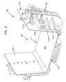
- FIG. 1is a perspective view of an embodiment of a trough system shown in exploded form.
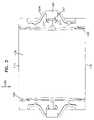
- FIG. 2is a perspective view of an embodiment of a coupler of the trough system of FIG. 1 .
- FIG. 3is a top view of the coupler of FIG. 2 .
- FIG. 4is a side view of an embodiment of a locking element of the trough system of FIG. 1 .
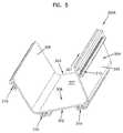
- FIG. 5is a perspective view of an embodiment of a trough member of the trough system of FIG. 1 .
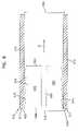
- FIG. 6is a side view of a portion of the trough member of FIG. 5 including a slot.
- FIG. 7is a side view of an embodiment of a clip of the trough system of FIG. 1 .
- FIG. 8is a cross-sectional view of a portion of the trough member of FIG. 5 including a clip.
- FIG. 9is a perspective view of another embodiment of a trough system.
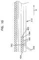
- FIG. 10is a cross-sectional view of a portion of a trough member partially coupled to a coupler.
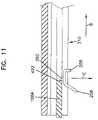
- FIG. 11is another cross-sectional view of the portion of the trough member fully coupled to the coupler of FIG. 10 .
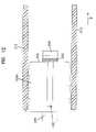
- FIG. 12is another cross-sectional view of the portion of the trough member fully coupled to the coupler of FIG. 10 .
- FIG. 13is another cross-sectional view of the portion of the trough member fully coupled to the coupler of FIG. 10 .
- the terms “couple” and “coupled”mean to join or attach a first element in relation to a second element, whether the attachment is made directly with the second element or indirectly through one or more intermediate components.
- the term “slot”means a space defined by one or more surfaces and can include, without limitation, T-slots, closed slots, flanges, and projections.
- FIG. 1shows an example trough system 10 including a coupler 100 for interconnecting trough members 300 A, 300 B.
- Coupler 100includes locking elements 107 A, 107 B, 107 C, 107 D.
- Trough members 300 A, 300 Binclude clips 108 A, 108 B, 108 C, 108 D, 108 E, 108 F, 108 G, 180 H.
- locking elements 107 A, 107 B, 107 C, 107 D and clips 108 A, 108 B, 108 C, 108 D, 108 E, 108 F, 108 G, 180 Hsecure the connection between coupler 100 and trough members 300 A, 300 B.
- coupler 100can be configured to release the connections between coupler 100 and trough members 300 A, 300 B.
- locking elements 107 A, 107 B, 107 C, 107 D and clips 108 A, 108 B, 108 C, 108 D, 108 E, 108 F, 108 G, 180 Hare tool-less (i.e., do not require the use of a separate tool to couple and uncouple trough members 300 A, 300 B to coupler 100 ).
- elements requiring one or more auxiliary toolsare also within the scope of the present disclosure.
- coupler 100includes a first guiding surface 101 and a second guiding surface 102 at least partially surrounding first guiding surface 101 , as well as a first coupler end 110 and a second coupler end 111 .
- a spacing 103is defined between first guiding surface 101 and second guiding surface 102 . Spacing 103 is sized to receive a trough member (e.g., trough members 300 A, 300 B) or another trough system component inserted into the spacing 103 in a longitudinal direction 190 .
- a trough membere.g., trough members 300 A, 300 B
- First guiding surface 101 of coupler 100is generally in the shape of a trough, including a first side wall portion 104 and a second side wall portion 105 , as well as a bottom wall portion 106 joining first and second side wall portions 104 and 105 .
- troughmeans any structure that defines an interior in which an element such as an optical cable can be maintained.
- Second guiding surface 102is also in the shape of a trough.
- a midpoint or midsection 175divides coupler 100 into first and second halves, and generally surrounds at least a portion of first guiding surface 101 .
- Locking element 107 Aincludes a main body 252 and arms 254 , 256 extending therefrom.
- a clip member 209 of main body 252is configured to couple locking element 107 A to coupler 100 .
- Clip member 209includes members 210 A, 210 B with wedges 211 at the ends thereof.
- Locking element 107 Ais coupled to coupler 100 by placing members 210 A, 210 B of clip member 209 through a frame member 166 formed in midpoint 175 of coupler 100 .
- wedges 211engage opposing sides of frame member 166 , and members 210 A, 210 B are compressed towards each other until wedges 211 clear frame member 166 . In this position, wedges 211 engage an end 167 of frame member 166 to maintain locking element 107 A on coupler 100 . Locking element 107 A can be removed from coupler 100 by compressing members 210 A, 210 B towards one another until wedges 211 clear end 167 of frame member 166 . In this position, clip member 209 can be removed from frame member 166 to remove locking element 107 A from coupler 100 .
- Each arm 254 , 256 of locking element 107 Aincludes a barb 262 , 264 extending therefrom.
- Outer ends 258 of arms 254 , 256extend outwardly in a direction opposite to that of barbs 262 , 264 to allow the user to easily grasp and move a respective arm into the unlocked position.
- Arms 254 , 256flex to allow ends 258 and barbs 262 , 264 to move independently and relative to main body 252 , as described further below.
- trough member 300 Ais shown in more detail.
- the phrase “trough member”is used to refer to any trough, fitting, railway, raceway, or similarly configured component including any number of ends. Although a specific embodiment of a trough member is shown in and described herein, other trough members can also be used.
- Trough member 300 Aincludes a first terminal end 302 and a second terminal end 303 .
- Trough member 300 Ais generally in the shape of a trough including first and second side walls 305 , 306 coupled by a bottom wall 307 , thereby defining an interior surface 308 and an exterior surface 309 .
- Walls 305 , 306 , 307are each generally planar.
- the exterior surface 309define one or more slots 310 on the side walls 305 and 306 and bottom wall 307 .
- Slots 310extend in a longitudinal direction 301 of the trough member 300 A from the first terminal end 302 to the second terminal end 303 .
- slot 310is formed by two walls 312 that define a space 314 therebetween.
- slots 310will be provided to correspond to at least one or more of locking element 107 A, 107 B, 107 C, 107 D, as described further below.
- the slots 310may be T-slots, as shown on the example embodiment of the trough 300 A.
- T-slotmeans a slot having a narrow access opening and a wider interior region.
- the slots 310may also be flanges or opposing projections.
- Example slot configurationsinclude two opposing walls that extend in the longitudinal direction 301 , although a single surface may also be used.
- the slots 310may not extend fully between the terminal ends of the trough member.
- the placement of the slots on the exterior surface of the trough membersmay be altered. More or fewer slots may also be provided.
- Clip 108 Aincludes a main body 410 with a first end 422 and a second end 424 .
- Clip 108 Ais generally shaped as a wedge or arrow to allow clip 108 A to be inserted into space 314 of slot 310 of trough member 300 A.
- Main body 410includes teeth 415 formed on opposing outer edges of main body 410 to engage portions of slot 310 of trough member 300 A when clip 108 A is inserted into slot 310 .
- Tabs 420are formed at second end 424 of main body 410 .
- Main body 410also includes a slot 430 extending from first end 422 that divides main body 410 into portions 432 , 434 . Slot 430 and tabs 420 facilitate insertion of clip 108 A into slot 310 of trough member 300 A, as described below.
- clip 108 Ais shown inserted into space 314 of slot 310 .
- first end 422 of clip 108 Ais introduced into space 314 of slot 310 and clip 108 A is slid into slot 310 in a direction A.
- a width 450 of clip 108 A(see FIG. 7 ) is slightly larger than a width 350 of walls 312 of slot 310 so that, when clip 108 is slid into slot 310 in direction A, teeth 415 engage walls 312 of slot 310 and portions 432 , 434 of main body 410 are compressed slightly towards one another.
- Clip 108 Ais slid in direction A until tabs 420 on end 424 contact end 311 of slot 310 , as shown in FIG. 8 .
- portions 432 , 434remain under slight compression, and the serrated shape of teeth 415 engage walls 312 to resist movement of clip 108 A in a direction opposite of that of direction A to maintain clip 108 A within slot 310 .
- clip 108 Ais made of metal. In other embodiments, other materials, such as plastic, can be used.
- clips 108 B, 108 C, 108 D, 108 E, 108 F, 108 G, and 108 Hcan be inserted into respective slots 310 of coupler 300 A in a similar manner.
- terminal ends 302 , 303 of the trough members 300 A, 300 Bare slidingly engaged in the spacing 103 between the first and second guiding surfaces 101 and 102 of the coupler 100 .
- the thickness of the walls of each of the trough members 300 A, 300 B, or the distance between the inner and outer surfaces 308 , 309are sized to fit within the spacing 103 of the coupler 100 .
- the coupler 100overlaps the terminal ends 302 , 303 of each of the trough members 300 A, 300 B to form the coupling, the overlap defining an overlap region.
- each trough member 300 A, 300 Bis inserted into a respective end 110 , 111 of the coupler 100 in a direction B, arms 254 , 256 of locking elements 107 A extend into slots 310 of trough members 300 A, 300 B.
- barb 262 of locking element 107 Acontacts second end 424 of clip 108 A and flexes slightly outward to ride along an outer surface 460 of clip 108 A as trough member 300 A is inserted into coupler 100 .
- barb 262slides past outer surface 460 of clip 108 A. In this position, barb 262 engages first end 422 of clip 108 A to resist movement of clip 108 A and attached trough member 300 A in a direction opposite to that of direction B.
- end 258 of arm 256is moved in a direction C until barb 262 clears first end 422 of clip 108 A. Once barb 262 clears first end 422 , trough member 300 A can be removed from spacing 103 of coupler 100 .
- Trough member 300 Bcan be coupled to the opposite end of coupler 100 in a similar manner.
- each end 258 of arms 254 , 256 of locking element 107 Acan be moved separately to separately release trough members 300 A, 300 B.
- both ends 258 of locking element 107 Acan be moved at the same time to release both trough members 300 A, 300 B at the same time.
- the other locking elements 107 B, 107 C, 107 D and clips 108 B, 108 C, 108 D, 108 E, 108 F, 108 G, 108 Hfunction in a manner similar to that of locking element 107 A and clip 108 A.
- An example method for coupling one or both of trough members 300 A, 300 B to coupler 100is as follows. Clips 108 A, 108 B, 108 C, 108 D, 108 E, 108 F, 108 G, 108 H are inserted into slots 310 on trough members 300 A, 300 B. Locking elements 107 A, 107 B, 107 C, 107 D are coupled to coupler 100 .
- Terminal end 302 of trough member 300 Ais inserted into spacing 103 of coupler 100 in direction 190 .
- barbs 262 of locking elements 107 A, 107 B, 107 C, 107 Dride along respective clips 108 A, 108 B, 108 C, 108 D in slots 310 of trough member 300 A.
- barbs 262clear clips 108 A, 108 B, 108 C, 108 D and contact first ends 422 of clips 108 A, 108 B, 108 C, 108 D.
- Trough member 300 Bcan be coupled to second coupler end 111 of coupler 100 in a similar manner.
- An example method of removing trough member 300 Aincludes moving ends 258 of arms 256 of locking elements 107 A, 107 B, 107 C, 107 D so that barbs 262 clear first ends 422 of clips 108 A, 108 B, 108 C, 108 D. Once barbs 262 clear first ends 422 of clips 108 A, 108 B, 108 C, 108 D, trough member 300 A can be removed from spacing 103 of coupler 100 . Trough member 300 B can be removed in a similar fashion.
- the locking elements disclosed hereinare tool-less in that the locking elements do not require a separate tool to move the locking elements from the locked position to the unlocked position and vice versa.
- the locking elementscan be moved from the locked position to the unlocked position through use of the user's hand.
- the locking elements disclosed hereinare auto-locking, in that the locking elements can be placed in the locked position prior to insertion of the trough member into the coupler. When the trough member is introduced into the coupler, the locking elements automatically lock the trough member to the coupler. The locking elements can subsequently be moved to the unlocked position to release the trough member from the coupler.
- the locking elementsinclude straight, rather than curved, arms.
- other features or componentsare included at the ends of the arms of the locking elements to assist a user in moving the arms and associated barbs away from the exterior surface of the trough members.
- a couplercan be configured to be coupled to more than two trough members, therefore including more than the first and second coupler ends.
- a greater number of locking elements and/or clipscan be presented for each coupler end, or, alternatively, fewer locking elements such as, for example, two on opposing sides, can be used.
Landscapes
- Physics & Mathematics (AREA)
- General Physics & Mathematics (AREA)
- Optics & Photonics (AREA)
- Supports For Pipes And Cables (AREA)
- Installation Of Indoor Wiring (AREA)
Abstract
Description
Claims (15)
Priority Applications (1)
| Application Number | Priority Date | Filing Date | Title |
|---|---|---|---|
| US11/677,184US7493005B2 (en) | 2007-02-21 | 2007-02-21 | Coupler for cable trough |
Applications Claiming Priority (1)
| Application Number | Priority Date | Filing Date | Title |
|---|---|---|---|
| US11/677,184US7493005B2 (en) | 2007-02-21 | 2007-02-21 | Coupler for cable trough |
Publications (2)
| Publication Number | Publication Date |
|---|---|
| US20080199142A1 US20080199142A1 (en) | 2008-08-21 |
| US7493005B2true US7493005B2 (en) | 2009-02-17 |
Family
ID=39706731
Family Applications (1)
| Application Number | Title | Priority Date | Filing Date |
|---|---|---|---|
| US11/677,184ActiveUS7493005B2 (en) | 2007-02-21 | 2007-02-21 | Coupler for cable trough |
Country Status (1)
| Country | Link |
|---|---|
| US (1) | US7493005B2 (en) |
Cited By (1)
| Publication number | Priority date | Publication date | Assignee | Title |
|---|---|---|---|---|
| US10444459B2 (en) | 2015-10-19 | 2019-10-15 | Commscope Technologies Llc | Articulating optical fiber guide system |
Families Citing this family (3)
| Publication number | Priority date | Publication date | Assignee | Title |
|---|---|---|---|---|
| CN105369898B (en)* | 2015-08-25 | 2017-10-13 | 河南奥斯派克科技有限公司 | Thin-wall channel assembled house based on BIM |
| USD887992S1 (en)* | 2018-04-25 | 2020-06-23 | Telect, Inc. | Cable trough attachment assembly |
| USD868004S1 (en) | 2018-04-25 | 2019-11-26 | Telect, Inc. | Cable trough lip |
Citations (89)
| Publication number | Priority date | Publication date | Assignee | Title |
|---|---|---|---|---|
| GB549840A (en) | 1941-09-08 | 1942-12-09 | Arthur Harry Stevens | Improvements in conduits for electric cables |
| US2316166A (en) | 1940-09-04 | 1943-04-13 | Nat Electric Prod Corp | Wiring duct |
| US2360159A (en) | 1942-11-06 | 1944-10-10 | Wm Burchenal | Conduit connector |
| US2569532A (en)* | 1948-06-09 | 1951-10-02 | Franklin W Marshall | Joining device |
| US2741499A (en) | 1951-08-18 | 1956-04-10 | Kelek Company | Raceway fitting providing access opening |
| US2821154A (en) | 1949-06-18 | 1958-01-28 | Jr James D Tennison | Couplings for joining lengths of trough gutters |
| US2823056A (en) | 1954-10-20 | 1958-02-11 | T J Cope Inc | Connecting means for cable-supporting trough systems and the like |
| US2834622A (en) | 1954-12-15 | 1958-05-13 | T J Cope Inc | Connecting means for cable-supporting trough systems and the like |
| US2880887A (en) | 1955-04-28 | 1959-04-07 | Buckeye Steel Castings Co | Retaining means for coupler carrier |
| US2891750A (en) | 1956-10-01 | 1959-06-23 | Gen Electric | Cable supporting system |
| US3022972A (en) | 1959-07-21 | 1962-02-27 | Burndy Corp | Supporting trough |
| US3042351A (en) | 1960-05-27 | 1962-07-03 | Bois Marvin A Du | Cable trays |
| US3188030A (en) | 1961-12-11 | 1965-06-08 | Fischer Arthur | Clamp or hanger for cables and the like |
| FR1479341A (en) | 1967-07-31 | |||
| US3351699A (en) | 1965-03-19 | 1967-11-07 | Danzer Metal Works Co | Raceway for electrical cables and wires adapted to retain rf energy |
| US3370121A (en) | 1967-06-26 | 1968-02-20 | Danzer Metal Works Co | Rf energy retaining raceway for communications cables |
| US3457598A (en) | 1968-08-09 | 1969-07-29 | Thomas & Betts Corp | Self-clinching bundling strap |
| US3471629A (en) | 1963-03-12 | 1969-10-07 | Ray O Leary | Electrical surface raceway wiring system |
| US3493917A (en) | 1967-08-01 | 1970-02-03 | Viking Industries | Connector locking means |
| US3603625A (en) | 1970-05-18 | 1971-09-07 | Textron Inc | Trenchduct connector units |
| GB1342085A (en) | 1971-04-19 | 1973-12-25 | Simplex Power Centre Ltd | |
| US3782420A (en) | 1971-04-14 | 1974-01-01 | Tehalit Kunststoffwerk Gmbh | Cable installation conduit with l and t joints |
| US3875618A (en) | 1973-12-10 | 1975-04-08 | Fastway Fasteners | Bundling tie |
| US3915420A (en) | 1974-10-07 | 1975-10-28 | Crouse Hinds Co | Cable tray |
| US4099749A (en) | 1974-04-08 | 1978-07-11 | Air-O-Mulder B.V. | Coupling sleeve |
| US4305236A (en) | 1980-01-14 | 1981-12-15 | Williams Robert F | Rain gutter system |
| DE3636412A1 (en) | 1986-10-25 | 1988-04-28 | Bettermann Obo Ohg | Connecting device for cable ducts (cable channels) |
| EP0315023A2 (en) | 1987-11-03 | 1989-05-10 | Swifts Of Scarborough Limited | Improvements relating to cable tray systems |
| US4854665A (en) | 1984-09-17 | 1989-08-08 | Endot Industries, Inc. | Coupling for joining axial sections of duct for fiber optic cables |
| US4954015A (en) | 1990-04-04 | 1990-09-04 | Gsw Inc. | Gutter seal |
| US5035092A (en) | 1990-08-13 | 1991-07-30 | Gsw Inc. | Nonsymmetrical eavestrough fitting |
| US5038528A (en) | 1990-05-08 | 1991-08-13 | Gsw Inc. | Gasket seal |
| US5067678A (en) | 1989-07-31 | 1991-11-26 | Adc Telecommunications, Inc. | Optic cable management system |
| US5078530A (en) | 1991-04-26 | 1992-01-07 | Permanent Solution Industries, Inc. | Plastic coupling device for connecting two building elements |
| US5100221A (en) | 1990-01-22 | 1992-03-31 | Porta Systems Corp. | Optical fiber cable distribution frame and support |
| US5134250A (en) | 1991-04-10 | 1992-07-28 | Panduit Corp. | Wiring duct |
| US5142606A (en) | 1990-01-22 | 1992-08-25 | Porta Systems Corp. | Optical fiber cable distribution frame and support |
| US5161580A (en) | 1990-08-27 | 1992-11-10 | Tyton Corporation | Cable duct fitting with removable cover |
| EP0571307A1 (en) | 1992-05-22 | 1993-11-24 | Max Petit | Self-assembly of cable duct pieces and method of manufacture |
| US5316243A (en) | 1989-07-31 | 1994-05-31 | Adc Telecommunications, Inc. | Optic cable management |
| USD348651S (en) | 1991-04-01 | 1994-07-12 | Adc Telecommunications, Inc. | Fiber trough coupling |
| EP0486442B1 (en) | 1990-11-13 | 1995-10-04 | TELEPLAST S.r.L. | A system of modular supports made up of three or more pieces, suitable for receiving ducts of different diameters |
| US5469893A (en) | 1993-12-21 | 1995-11-28 | Panduit Corp. | Tab and slot fiber optic fitting |
| US5547307A (en) | 1993-12-10 | 1996-08-20 | Legrand | Device for butt-jointing perforated cable tray sections |
| US5617678A (en) | 1992-08-28 | 1997-04-08 | Gsw Inc. | Eavestrough system |
| US5720567A (en) | 1995-04-19 | 1998-02-24 | Sigma-Aldrich Company | Cable tray system |
| US5753855A (en) | 1994-11-17 | 1998-05-19 | Panduit Corp. | Wiring duct fittings |
| US5752781A (en) | 1997-03-14 | 1998-05-19 | Adc Telecommunications, Inc. | Fiber trough coupling |
| US5792993A (en) | 1997-04-07 | 1998-08-11 | Sigma-Aldrich Company | Wireway sealing device |
| EP0874260A1 (en) | 1997-04-21 | 1998-10-28 | Polva Pipelife B.V. | Duct system, coupling, and also method for manufacturing a duct system |
| USD402263S (en) | 1996-12-06 | 1998-12-08 | Panduit Corp. | Straight single raceway fitting |
| USD402262S (en) | 1996-12-06 | 1998-12-08 | Panduit Corp. | Straight dual raceway fitting |
| WO1999006746A1 (en) | 1997-08-01 | 1999-02-11 | Metal Deploye S.A. | Wire cable rack equipped with at least one fixing accessory, and corresponding fixing accessory |
| USD413306S (en) | 1998-06-04 | 1999-08-31 | Panduit Corp. | Right angle single raceway fitting |
| US5995699A (en) | 1998-01-05 | 1999-11-30 | The Wiremold Company | Fiber optic cable raceway system cross reference to related applications |
| US5998732A (en) | 1998-01-13 | 1999-12-07 | Panduit Corp. | Raceway outlet station |
| USD419962S (en) | 1998-01-13 | 2000-02-01 | Panduit Corp. | Raceway outlet station |
| US6037543A (en) | 1994-11-17 | 2000-03-14 | Panduit Corp. | Wiring duct fittings |
| USD430543S (en) | 2000-02-07 | 2000-09-05 | Panduit Corp. | Raceway cover |
| EP1033800A1 (en) | 1999-03-03 | 2000-09-06 | Panduit Corporation | Wireway system having a pivotable cover |
| US6126122A (en) | 1997-11-06 | 2000-10-03 | Sioux Chief Manufacturing Co., Inc. | Double ratchet arm pipe clamp |
| US6143984A (en) | 1998-04-02 | 2000-11-07 | Tyco Electronics Corporation | Adjustable channel connector for a cable raceway system |
| WO2000075550A1 (en) | 1999-06-02 | 2000-12-14 | Warren & Brown Manufacturing Pty. Ltd. | Hollow member connector |
| US6188024B1 (en) | 1998-02-03 | 2001-02-13 | Aparellaje Electrico, S.A. | Elbow for the angular connection of two stretches of raceway for electrical cable system |
| US6193434B1 (en) | 1996-07-26 | 2001-02-27 | Metal Deploye S.A. | Connecting splice for cable trough sections, and resulting cable trough sections |
| EP1160950A2 (en) | 2000-06-01 | 2001-12-05 | Panduit Corp. | Cable duct coupler with locking clip |
| EP1160949A2 (en) | 2000-06-01 | 2001-12-05 | Panduit Corporation | Split fiber cover and raceway fitting |
| US20020006312A1 (en) | 2000-07-12 | 2002-01-17 | Legrand And Legrand Snc | Trunking connecting device |
| WO2002018991A1 (en) | 2000-08-28 | 2002-03-07 | Telect, Inc. | Fiber transition trough coupling system |
| WO2002031939A1 (en) | 2000-10-13 | 2002-04-18 | Alan Dick & Co. Ltd. | Cable tray |
| WO2002033445A2 (en) | 2000-08-28 | 2002-04-25 | Telect, Inc. | Fiber trough coupling system |
| US20020096606A1 (en) | 2000-06-01 | 2002-07-25 | Bernard William A. | Cable duct coupler |
| US6454485B2 (en) | 1999-03-10 | 2002-09-24 | Adaptive Engineering Lab, Inc. | Bi-directional retainer |
| US6463631B2 (en) | 2000-05-17 | 2002-10-15 | Kitagawa Industries Co., Inc. | Binding tool |
| EP1249912A1 (en) | 2001-04-13 | 2002-10-16 | Vergokan | Cable-trough joint |
| WO2002086576A1 (en) | 2001-04-25 | 2002-10-31 | Adc Telecommunications, Inc. | Articulated trough system for communication cables |
| DE10212285A1 (en) | 2001-05-15 | 2002-11-21 | Barad Systems Gmbh | Cable channel corner piece has between two first or second channel parts, hinge and in at least second or first channel part, plate piece |
| US6512875B1 (en) | 2000-10-06 | 2003-01-28 | Adc Telecommunications, Inc. | Optical cable troughs, fittings, and couplings |
| US6520192B1 (en) | 2001-11-14 | 2003-02-18 | Albert Chong-Jen Lo | Extensible positioning device of the shank of an umbrella |
| US6603073B2 (en) | 2001-09-12 | 2003-08-05 | Adc Telecommunications, Inc. | Snap together cable trough system |
| US20030147690A1 (en) | 2000-03-20 | 2003-08-07 | Roennquist Lennart | Connection device, box and clamp |
| US20030177628A1 (en) | 2002-02-21 | 2003-09-25 | Mark Viklund | Cable ducting joiner |
| US20030183732A1 (en) | 2002-03-27 | 2003-10-02 | Adc Telecommunications, Inc. | Coupler for cable trough |
| US6634825B2 (en) | 2000-09-18 | 2003-10-21 | Bluefin Robotics Corporation | Apparatus for joining cylindrical sections |
| WO2004006400A1 (en) | 2002-07-03 | 2004-01-15 | Richard John Thompson | Trunking and coupling means therefor |
| US6709186B2 (en) | 2001-11-16 | 2004-03-23 | Adc Telecommunications, Inc. | Coupler for cable trough |
| US6810191B2 (en) | 2001-07-20 | 2004-10-26 | Adc Telecommunications, Inc. | Cable trough cover |
| US7029195B2 (en) | 2002-03-27 | 2006-04-18 | Adc Telecommunications, Inc. | Coupler for cable trough |
| US7246778B2 (en) | 2003-03-27 | 2007-07-24 | Panduit Corp. | Releasable barb assembly |
- 2007
- 2007-02-21USUS11/677,184patent/US7493005B2/enactiveActive
Patent Citations (103)
| Publication number | Priority date | Publication date | Assignee | Title |
|---|---|---|---|---|
| FR1479341A (en) | 1967-07-31 | |||
| US2316166A (en) | 1940-09-04 | 1943-04-13 | Nat Electric Prod Corp | Wiring duct |
| GB549840A (en) | 1941-09-08 | 1942-12-09 | Arthur Harry Stevens | Improvements in conduits for electric cables |
| US2360159A (en) | 1942-11-06 | 1944-10-10 | Wm Burchenal | Conduit connector |
| US2569532A (en)* | 1948-06-09 | 1951-10-02 | Franklin W Marshall | Joining device |
| US2821154A (en) | 1949-06-18 | 1958-01-28 | Jr James D Tennison | Couplings for joining lengths of trough gutters |
| US2741499A (en) | 1951-08-18 | 1956-04-10 | Kelek Company | Raceway fitting providing access opening |
| US2823056A (en) | 1954-10-20 | 1958-02-11 | T J Cope Inc | Connecting means for cable-supporting trough systems and the like |
| US2834622A (en) | 1954-12-15 | 1958-05-13 | T J Cope Inc | Connecting means for cable-supporting trough systems and the like |
| US2880887A (en) | 1955-04-28 | 1959-04-07 | Buckeye Steel Castings Co | Retaining means for coupler carrier |
| US2891750A (en) | 1956-10-01 | 1959-06-23 | Gen Electric | Cable supporting system |
| US3022972A (en) | 1959-07-21 | 1962-02-27 | Burndy Corp | Supporting trough |
| US3042351A (en) | 1960-05-27 | 1962-07-03 | Bois Marvin A Du | Cable trays |
| US3188030A (en) | 1961-12-11 | 1965-06-08 | Fischer Arthur | Clamp or hanger for cables and the like |
| US3471629A (en) | 1963-03-12 | 1969-10-07 | Ray O Leary | Electrical surface raceway wiring system |
| US3351699A (en) | 1965-03-19 | 1967-11-07 | Danzer Metal Works Co | Raceway for electrical cables and wires adapted to retain rf energy |
| US3370121A (en) | 1967-06-26 | 1968-02-20 | Danzer Metal Works Co | Rf energy retaining raceway for communications cables |
| US3493917A (en) | 1967-08-01 | 1970-02-03 | Viking Industries | Connector locking means |
| US3457598A (en) | 1968-08-09 | 1969-07-29 | Thomas & Betts Corp | Self-clinching bundling strap |
| US3603625A (en) | 1970-05-18 | 1971-09-07 | Textron Inc | Trenchduct connector units |
| US3782420A (en) | 1971-04-14 | 1974-01-01 | Tehalit Kunststoffwerk Gmbh | Cable installation conduit with l and t joints |
| GB1342085A (en) | 1971-04-19 | 1973-12-25 | Simplex Power Centre Ltd | |
| US3875618A (en) | 1973-12-10 | 1975-04-08 | Fastway Fasteners | Bundling tie |
| US4099749A (en) | 1974-04-08 | 1978-07-11 | Air-O-Mulder B.V. | Coupling sleeve |
| US3915420A (en) | 1974-10-07 | 1975-10-28 | Crouse Hinds Co | Cable tray |
| US4305236A (en) | 1980-01-14 | 1981-12-15 | Williams Robert F | Rain gutter system |
| US4854665A (en) | 1984-09-17 | 1989-08-08 | Endot Industries, Inc. | Coupling for joining axial sections of duct for fiber optic cables |
| DE3636412A1 (en) | 1986-10-25 | 1988-04-28 | Bettermann Obo Ohg | Connecting device for cable ducts (cable channels) |
| EP0315023A2 (en) | 1987-11-03 | 1989-05-10 | Swifts Of Scarborough Limited | Improvements relating to cable tray systems |
| US5067678A (en) | 1989-07-31 | 1991-11-26 | Adc Telecommunications, Inc. | Optic cable management system |
| US5316243A (en) | 1989-07-31 | 1994-05-31 | Adc Telecommunications, Inc. | Optic cable management |
| US5142606A (en) | 1990-01-22 | 1992-08-25 | Porta Systems Corp. | Optical fiber cable distribution frame and support |
| US5100221A (en) | 1990-01-22 | 1992-03-31 | Porta Systems Corp. | Optical fiber cable distribution frame and support |
| US4954015A (en) | 1990-04-04 | 1990-09-04 | Gsw Inc. | Gutter seal |
| US5038528A (en) | 1990-05-08 | 1991-08-13 | Gsw Inc. | Gasket seal |
| US5035092A (en) | 1990-08-13 | 1991-07-30 | Gsw Inc. | Nonsymmetrical eavestrough fitting |
| US5161580A (en) | 1990-08-27 | 1992-11-10 | Tyton Corporation | Cable duct fitting with removable cover |
| EP0486442B1 (en) | 1990-11-13 | 1995-10-04 | TELEPLAST S.r.L. | A system of modular supports made up of three or more pieces, suitable for receiving ducts of different diameters |
| USD348651S (en) | 1991-04-01 | 1994-07-12 | Adc Telecommunications, Inc. | Fiber trough coupling |
| US5134250A (en) | 1991-04-10 | 1992-07-28 | Panduit Corp. | Wiring duct |
| US5078530A (en) | 1991-04-26 | 1992-01-07 | Permanent Solution Industries, Inc. | Plastic coupling device for connecting two building elements |
| EP0571307A1 (en) | 1992-05-22 | 1993-11-24 | Max Petit | Self-assembly of cable duct pieces and method of manufacture |
| US5617678A (en) | 1992-08-28 | 1997-04-08 | Gsw Inc. | Eavestrough system |
| US5547307A (en) | 1993-12-10 | 1996-08-20 | Legrand | Device for butt-jointing perforated cable tray sections |
| US5469893A (en) | 1993-12-21 | 1995-11-28 | Panduit Corp. | Tab and slot fiber optic fitting |
| US5753855A (en) | 1994-11-17 | 1998-05-19 | Panduit Corp. | Wiring duct fittings |
| US6037543A (en) | 1994-11-17 | 2000-03-14 | Panduit Corp. | Wiring duct fittings |
| US5720567A (en) | 1995-04-19 | 1998-02-24 | Sigma-Aldrich Company | Cable tray system |
| US6402418B1 (en) | 1996-07-26 | 2002-06-11 | Metal Deploye S.A. | Coupling for assembling cable tray unit sections and cable tray unit sections obtained |
| US6193434B1 (en) | 1996-07-26 | 2001-02-27 | Metal Deploye S.A. | Connecting splice for cable trough sections, and resulting cable trough sections |
| USD402262S (en) | 1996-12-06 | 1998-12-08 | Panduit Corp. | Straight dual raceway fitting |
| USD402263S (en) | 1996-12-06 | 1998-12-08 | Panduit Corp. | Straight single raceway fitting |
| USD447737S1 (en) | 1996-12-06 | 2001-09-11 | Panduit Corp. | Right angle dual raceway fitting |
| US5752781A (en) | 1997-03-14 | 1998-05-19 | Adc Telecommunications, Inc. | Fiber trough coupling |
| US5792993A (en) | 1997-04-07 | 1998-08-11 | Sigma-Aldrich Company | Wireway sealing device |
| EP0874260A1 (en) | 1997-04-21 | 1998-10-28 | Polva Pipelife B.V. | Duct system, coupling, and also method for manufacturing a duct system |
| WO1999006746A1 (en) | 1997-08-01 | 1999-02-11 | Metal Deploye S.A. | Wire cable rack equipped with at least one fixing accessory, and corresponding fixing accessory |
| US6126122A (en) | 1997-11-06 | 2000-10-03 | Sioux Chief Manufacturing Co., Inc. | Double ratchet arm pipe clamp |
| US5995699A (en) | 1998-01-05 | 1999-11-30 | The Wiremold Company | Fiber optic cable raceway system cross reference to related applications |
| US5998732A (en) | 1998-01-13 | 1999-12-07 | Panduit Corp. | Raceway outlet station |
| USD419962S (en) | 1998-01-13 | 2000-02-01 | Panduit Corp. | Raceway outlet station |
| US6188024B1 (en) | 1998-02-03 | 2001-02-13 | Aparellaje Electrico, S.A. | Elbow for the angular connection of two stretches of raceway for electrical cable system |
| US6143984A (en) | 1998-04-02 | 2000-11-07 | Tyco Electronics Corporation | Adjustable channel connector for a cable raceway system |
| USD413306S (en) | 1998-06-04 | 1999-08-31 | Panduit Corp. | Right angle single raceway fitting |
| EP1033800A1 (en) | 1999-03-03 | 2000-09-06 | Panduit Corporation | Wireway system having a pivotable cover |
| US6454485B2 (en) | 1999-03-10 | 2002-09-24 | Adaptive Engineering Lab, Inc. | Bi-directional retainer |
| WO2000075550A1 (en) | 1999-06-02 | 2000-12-14 | Warren & Brown Manufacturing Pty. Ltd. | Hollow member connector |
| USD430543S (en) | 2000-02-07 | 2000-09-05 | Panduit Corp. | Raceway cover |
| US20030147690A1 (en) | 2000-03-20 | 2003-08-07 | Roennquist Lennart | Connection device, box and clamp |
| US6463631B2 (en) | 2000-05-17 | 2002-10-15 | Kitagawa Industries Co., Inc. | Binding tool |
| EP1160949A2 (en) | 2000-06-01 | 2001-12-05 | Panduit Corporation | Split fiber cover and raceway fitting |
| EP1160950A2 (en) | 2000-06-01 | 2001-12-05 | Panduit Corp. | Cable duct coupler with locking clip |
| US6476327B1 (en) | 2000-06-01 | 2002-11-05 | Panduit Corp. | Split fiber cover and raceway fitting |
| US6634605B2 (en) | 2000-06-01 | 2003-10-21 | Panduit Corp. | Cable duct coupler |
| US20020096606A1 (en) | 2000-06-01 | 2002-07-25 | Bernard William A. | Cable duct coupler |
| US6450458B1 (en) | 2000-06-01 | 2002-09-17 | Panduit Corp. | Cable duct coupler with locking clip |
| US6523791B2 (en) | 2000-06-01 | 2003-02-25 | Panduit Corp. | Cable duct coupler |
| US20020006312A1 (en) | 2000-07-12 | 2002-01-17 | Legrand And Legrand Snc | Trunking connecting device |
| US6424779B1 (en) | 2000-08-28 | 2002-07-23 | Steven W. Ellison | Fiber trough coupling system |
| WO2002018991A1 (en) | 2000-08-28 | 2002-03-07 | Telect, Inc. | Fiber transition trough coupling system |
| WO2002033445A2 (en) | 2000-08-28 | 2002-04-25 | Telect, Inc. | Fiber trough coupling system |
| US6634825B2 (en) | 2000-09-18 | 2003-10-21 | Bluefin Robotics Corporation | Apparatus for joining cylindrical sections |
| US6512875B1 (en) | 2000-10-06 | 2003-01-28 | Adc Telecommunications, Inc. | Optical cable troughs, fittings, and couplings |
| WO2002031939A1 (en) | 2000-10-13 | 2002-04-18 | Alan Dick & Co. Ltd. | Cable tray |
| EP1249912A1 (en) | 2001-04-13 | 2002-10-16 | Vergokan | Cable-trough joint |
| WO2002086576A1 (en) | 2001-04-25 | 2002-10-31 | Adc Telecommunications, Inc. | Articulated trough system for communication cables |
| DE10212285A1 (en) | 2001-05-15 | 2002-11-21 | Barad Systems Gmbh | Cable channel corner piece has between two first or second channel parts, hinge and in at least second or first channel part, plate piece |
| US6810191B2 (en) | 2001-07-20 | 2004-10-26 | Adc Telecommunications, Inc. | Cable trough cover |
| US6603073B2 (en) | 2001-09-12 | 2003-08-05 | Adc Telecommunications, Inc. | Snap together cable trough system |
| US6520192B1 (en) | 2001-11-14 | 2003-02-18 | Albert Chong-Jen Lo | Extensible positioning device of the shank of an umbrella |
| US20040159750A1 (en) | 2001-11-16 | 2004-08-19 | Adc Telecommunications, Inc. | Coupler for cable trough |
| US7175137B2 (en) | 2001-11-16 | 2007-02-13 | Adc Telecommunications, Inc. | Coupler for cable trough |
| US6709186B2 (en) | 2001-11-16 | 2004-03-23 | Adc Telecommunications, Inc. | Coupler for cable trough |
| US20030177628A1 (en) | 2002-02-21 | 2003-09-25 | Mark Viklund | Cable ducting joiner |
| US20030183731A1 (en) | 2002-03-27 | 2003-10-02 | Ferris Matthew D. | Coupler for cable trough |
| US6715719B2 (en) | 2002-03-27 | 2004-04-06 | Adc Telecommunications, Inc. | Coupler for cable trough |
| US7029195B2 (en) | 2002-03-27 | 2006-04-18 | Adc Telecommunications, Inc. | Coupler for cable trough |
| US7093997B2 (en) | 2002-03-27 | 2006-08-22 | Adc Telecommunications, Inc. | Coupler for cable trough |
| US20060210356A1 (en) | 2002-03-27 | 2006-09-21 | Adc Telecommunications, Inc. | Coupler for Cable Trough |
| US20060261240A1 (en) | 2002-03-27 | 2006-11-23 | Adc Telecommunications, Inc. | Coupler for Cable Trough |
| US20030183732A1 (en) | 2002-03-27 | 2003-10-02 | Adc Telecommunications, Inc. | Coupler for cable trough |
| WO2004006400A1 (en) | 2002-07-03 | 2004-01-15 | Richard John Thompson | Trunking and coupling means therefor |
| US7246778B2 (en) | 2003-03-27 | 2007-07-24 | Panduit Corp. | Releasable barb assembly |
Non-Patent Citations (21)
| Title |
|---|
| Exhibit A, Ditel, Inc.; Ditel UPL-1000/UPT-1000/Corner Cable Guides; product information, 2 pages, (C) 1986. |
| Exhibit A, Ditel, Inc.; Ditel UPL-1000/UPT-1000/Corner Cable Guides; product information, 2 pages, © 1986. |
| Exhibit B, ADC Telecommunications, Inc.; FiberGuide(TM), Fiber Management System, 6 pages front and back printed, 16/1989. |
| Exhibit B, ADC Telecommunications, Inc.; FiberGuide™, Fiber Management System, 6 pages front and back printed, 16/1989. |
| Exhibit C, Warren & Brown Technologies Pty. Ltd., Fibre Optic Management Systems, Component Selection Guide, 19 pages of product information. Source: www.warrenandbrown.com.au (admitted prior art as of the filing date). |
| Exhibit D, Panduit Network Connectivity Group, FiberRunner(TM) 6x4 Routing System Product Brochure, 2 pages, (C) Panduit Corp. 2000. |
| Exhibit D, Panduit Network Connectivity Group, FiberRunner™ 6×4 Routing System Product Brochure, 2 pages, © Panduit Corp. 2000. |
| Exhibit E, Panduit Corp. FiberRunner(TM) 4x4 Quiklock(TM) Coupler (FRBC4x4) Customer Drawing, 1 page, Jul. 13, 2001. |
| Exhibit E, Panduit Corp. FiberRunner™ 4×4 Quiklock™ Coupler (FRBC4×4) Customer Drawing, 1 page, Jul. 13, 2001. |
| Exhibit F, Panduit Corp. FiberRunner(TM) 6x4 Quiklock(TM) Coupler (FRBC6x4) Customer Drawing, 1 page, May 10, 2000. |
| Exhibit F, Panduit Corp. FiberRunner™ 6×4 Quiklock™ Coupler (FRBC6×4) Customer Drawing, 1 page, May 10, 2000. |
| Exhibit G, Panduit Corp. FiberRunner(TM) 12x4 Quiklock(TM) Coupler (FRBC12x4) Customer Drawing, 1 page, Jan. 3, 2001. |
| Exhibit G, Panduit Corp. FiberRunner™ 12×4 Quiklock™ Coupler (FRBC12×4) Customer Drawing, 1 page, Jan. 3, 2001. |
| Exhibits H-Y, Photographs of various Panduit products (admitted prior art as of the filing date). |
| U.S. Appl. No. 11/425,625, filed on Jun. 21, 2006. |
| U.S. Appl. No. 11/677,174, filed on Feb. 21, 2007. |
| U.S. Appl. No. 11/677,181, filed on Feb. 21, 2007. |
| U.S. Appl. No. 11/677,188, filed on Feb. 21, 2007. |
| U.S. Appl. No. 11/677,193, filed on Feb. 21, 2007. |
| U.S. Appl. No. 11/677,200, filed on Feb. 21, 2007. |
| U.S. Appl. No. 11/677,203, filed on Feb. 21, 2007. |
Cited By (3)
| Publication number | Priority date | Publication date | Assignee | Title |
|---|---|---|---|---|
| US10444459B2 (en) | 2015-10-19 | 2019-10-15 | Commscope Technologies Llc | Articulating optical fiber guide system |
| US10823929B2 (en) | 2015-10-19 | 2020-11-03 | Commscope Technologies Llc | Articulating optical fiber guide system |
| US11487072B2 (en) | 2015-10-19 | 2022-11-01 | Commscope Technologies Llc | Articulating optical fiber guide system |
Also Published As
| Publication number | Publication date |
|---|---|
| US20080199142A1 (en) | 2008-08-21 |
Similar Documents
| Publication | Publication Date | Title |
|---|---|---|
| US20190064467A1 (en) | Coupler for Cable Trough | |
| US8256723B2 (en) | Cable routing devices with integrated couplers | |
| US7614817B2 (en) | Coupler for cable trough | |
| US9356436B2 (en) | Cable trough system and method | |
| US8254744B2 (en) | Cable trough system and method | |
| US7896295B2 (en) | Coupler for cable trough | |
| US7493005B2 (en) | Coupler for cable trough | |
| US7584929B2 (en) | Coupler for cable trough | |
| US7481597B2 (en) | Coupler for cable trough | |
| US7815152B2 (en) | Coupler for cable trough | |
| US7463809B2 (en) | Coupler for cable trough | |
| US7504583B2 (en) | Coupler for cable trough | |
| US20080197243A1 (en) | Coupler for Cable Trough |
Legal Events
| Date | Code | Title | Description |
|---|---|---|---|
| AS | Assignment | Owner name:ADC TELECOMMUNICATIONS, INC., MINNESOTA Free format text:ASSIGNMENT OF ASSIGNORS INTEREST;ASSIGNOR:BECK, RONALD A.;REEL/FRAME:018918/0783 Effective date:20070219 | |
| STCF | Information on status: patent grant | Free format text:PATENTED CASE | |
| FPAY | Fee payment | Year of fee payment:4 | |
| AS | Assignment | Owner name:TYCO ELECTRONICS SERVICES GMBH, SWITZERLAND Free format text:ASSIGNMENT OF ASSIGNORS INTEREST;ASSIGNOR:ADC TELECOMMUNICATIONS, INC.;REEL/FRAME:036060/0174 Effective date:20110930 | |
| AS | Assignment | Owner name:COMMSCOPE EMEA LIMITED, IRELAND Free format text:ASSIGNMENT OF ASSIGNORS INTEREST;ASSIGNOR:TYCO ELECTRONICS SERVICES GMBH;REEL/FRAME:036956/0001 Effective date:20150828 | |
| AS | Assignment | Owner name:COMMSCOPE TECHNOLOGIES LLC, NORTH CAROLINA Free format text:ASSIGNMENT OF ASSIGNORS INTEREST;ASSIGNOR:COMMSCOPE EMEA LIMITED;REEL/FRAME:037012/0001 Effective date:20150828 | |
| AS | Assignment | Owner name:JPMORGAN CHASE BANK, N.A., AS COLLATERAL AGENT, ILLINOIS Free format text:PATENT SECURITY AGREEMENT (TERM);ASSIGNOR:COMMSCOPE TECHNOLOGIES LLC;REEL/FRAME:037513/0709 Effective date:20151220 Owner name:JPMORGAN CHASE BANK, N.A., AS COLLATERAL AGENT, ILLINOIS Free format text:PATENT SECURITY AGREEMENT (ABL);ASSIGNOR:COMMSCOPE TECHNOLOGIES LLC;REEL/FRAME:037514/0196 Effective date:20151220 Owner name:JPMORGAN CHASE BANK, N.A., AS COLLATERAL AGENT, IL Free format text:PATENT SECURITY AGREEMENT (TERM);ASSIGNOR:COMMSCOPE TECHNOLOGIES LLC;REEL/FRAME:037513/0709 Effective date:20151220 Owner name:JPMORGAN CHASE BANK, N.A., AS COLLATERAL AGENT, IL Free format text:PATENT SECURITY AGREEMENT (ABL);ASSIGNOR:COMMSCOPE TECHNOLOGIES LLC;REEL/FRAME:037514/0196 Effective date:20151220 | |
| FPAY | Fee payment | Year of fee payment:8 | |
| AS | Assignment | Owner name:COMMSCOPE, INC. OF NORTH CAROLINA, NORTH CAROLINA Free format text:RELEASE BY SECURED PARTY;ASSIGNOR:JPMORGAN CHASE BANK, N.A.;REEL/FRAME:048840/0001 Effective date:20190404 Owner name:ALLEN TELECOM LLC, ILLINOIS Free format text:RELEASE BY SECURED PARTY;ASSIGNOR:JPMORGAN CHASE BANK, N.A.;REEL/FRAME:048840/0001 Effective date:20190404 Owner name:COMMSCOPE TECHNOLOGIES LLC, NORTH CAROLINA Free format text:RELEASE BY SECURED PARTY;ASSIGNOR:JPMORGAN CHASE BANK, N.A.;REEL/FRAME:048840/0001 Effective date:20190404 Owner name:ANDREW LLC, NORTH CAROLINA Free format text:RELEASE BY SECURED PARTY;ASSIGNOR:JPMORGAN CHASE BANK, N.A.;REEL/FRAME:048840/0001 Effective date:20190404 Owner name:REDWOOD SYSTEMS, INC., NORTH CAROLINA Free format text:RELEASE BY SECURED PARTY;ASSIGNOR:JPMORGAN CHASE BANK, N.A.;REEL/FRAME:048840/0001 Effective date:20190404 Owner name:REDWOOD SYSTEMS, INC., NORTH CAROLINA Free format text:RELEASE BY SECURED PARTY;ASSIGNOR:JPMORGAN CHASE BANK, N.A.;REEL/FRAME:049260/0001 Effective date:20190404 Owner name:COMMSCOPE, INC. OF NORTH CAROLINA, NORTH CAROLINA Free format text:RELEASE BY SECURED PARTY;ASSIGNOR:JPMORGAN CHASE BANK, N.A.;REEL/FRAME:049260/0001 Effective date:20190404 Owner name:COMMSCOPE TECHNOLOGIES LLC, NORTH CAROLINA Free format text:RELEASE BY SECURED PARTY;ASSIGNOR:JPMORGAN CHASE BANK, N.A.;REEL/FRAME:049260/0001 Effective date:20190404 Owner name:ALLEN TELECOM LLC, ILLINOIS Free format text:RELEASE BY SECURED PARTY;ASSIGNOR:JPMORGAN CHASE BANK, N.A.;REEL/FRAME:049260/0001 Effective date:20190404 Owner name:ANDREW LLC, NORTH CAROLINA Free format text:RELEASE BY SECURED PARTY;ASSIGNOR:JPMORGAN CHASE BANK, N.A.;REEL/FRAME:049260/0001 Effective date:20190404 | |
| AS | Assignment | Owner name:WILMINGTON TRUST, NATIONAL ASSOCIATION, AS COLLATE Free format text:PATENT SECURITY AGREEMENT;ASSIGNOR:COMMSCOPE TECHNOLOGIES LLC;REEL/FRAME:049892/0051 Effective date:20190404 Owner name:JPMORGAN CHASE BANK, N.A., NEW YORK Free format text:TERM LOAN SECURITY AGREEMENT;ASSIGNORS:COMMSCOPE, INC. OF NORTH CAROLINA;COMMSCOPE TECHNOLOGIES LLC;ARRIS ENTERPRISES LLC;AND OTHERS;REEL/FRAME:049905/0504 Effective date:20190404 Owner name:JPMORGAN CHASE BANK, N.A., NEW YORK Free format text:ABL SECURITY AGREEMENT;ASSIGNORS:COMMSCOPE, INC. OF NORTH CAROLINA;COMMSCOPE TECHNOLOGIES LLC;ARRIS ENTERPRISES LLC;AND OTHERS;REEL/FRAME:049892/0396 Effective date:20190404 Owner name:WILMINGTON TRUST, NATIONAL ASSOCIATION, AS COLLATERAL AGENT, CONNECTICUT Free format text:PATENT SECURITY AGREEMENT;ASSIGNOR:COMMSCOPE TECHNOLOGIES LLC;REEL/FRAME:049892/0051 Effective date:20190404 | |
| MAFP | Maintenance fee payment | Free format text:PAYMENT OF MAINTENANCE FEE, 12TH YEAR, LARGE ENTITY (ORIGINAL EVENT CODE: M1553); ENTITY STATUS OF PATENT OWNER: LARGE ENTITY Year of fee payment:12 | |
| AS | Assignment | Owner name:WILMINGTON TRUST, DELAWARE Free format text:SECURITY INTEREST;ASSIGNORS:ARRIS SOLUTIONS, INC.;ARRIS ENTERPRISES LLC;COMMSCOPE TECHNOLOGIES LLC;AND OTHERS;REEL/FRAME:060752/0001 Effective date:20211115 | |
| AS | Assignment | Owner name:APOLLO ADMINISTRATIVE AGENCY LLC, NEW YORK Free format text:SECURITY INTEREST;ASSIGNORS:ARRIS ENTERPRISES LLC;COMMSCOPE TECHNOLOGIES LLC;COMMSCOPE INC., OF NORTH CAROLINA;AND OTHERS;REEL/FRAME:069889/0114 Effective date:20241217 | |
| AS | Assignment | Owner name:RUCKUS WIRELESS, LLC (F/K/A RUCKUS WIRELESS, INC.), NORTH CAROLINA Free format text:RELEASE OF SECURITY INTEREST AT REEL/FRAME 049905/0504;ASSIGNOR:JPMORGAN CHASE BANK, N.A., AS COLLATERAL AGENT;REEL/FRAME:071477/0255 Effective date:20241217 Owner name:COMMSCOPE TECHNOLOGIES LLC, NORTH CAROLINA Free format text:RELEASE OF SECURITY INTEREST AT REEL/FRAME 049905/0504;ASSIGNOR:JPMORGAN CHASE BANK, N.A., AS COLLATERAL AGENT;REEL/FRAME:071477/0255 Effective date:20241217 Owner name:COMMSCOPE, INC. OF NORTH CAROLINA, NORTH CAROLINA Free format text:RELEASE OF SECURITY INTEREST AT REEL/FRAME 049905/0504;ASSIGNOR:JPMORGAN CHASE BANK, N.A., AS COLLATERAL AGENT;REEL/FRAME:071477/0255 Effective date:20241217 Owner name:ARRIS SOLUTIONS, INC., NORTH CAROLINA Free format text:RELEASE OF SECURITY INTEREST AT REEL/FRAME 049905/0504;ASSIGNOR:JPMORGAN CHASE BANK, N.A., AS COLLATERAL AGENT;REEL/FRAME:071477/0255 Effective date:20241217 Owner name:ARRIS TECHNOLOGY, INC., NORTH CAROLINA Free format text:RELEASE OF SECURITY INTEREST AT REEL/FRAME 049905/0504;ASSIGNOR:JPMORGAN CHASE BANK, N.A., AS COLLATERAL AGENT;REEL/FRAME:071477/0255 Effective date:20241217 Owner name:ARRIS ENTERPRISES LLC (F/K/A ARRIS ENTERPRISES, INC.), NORTH CAROLINA Free format text:RELEASE OF SECURITY INTEREST AT REEL/FRAME 049905/0504;ASSIGNOR:JPMORGAN CHASE BANK, N.A., AS COLLATERAL AGENT;REEL/FRAME:071477/0255 Effective date:20241217 |