US7492806B2 - Compact mid-IR laser - Google Patents
Compact mid-IR laserDownload PDFInfo
- Publication number
- US7492806B2 US7492806B2US11/154,264US15426405AUS7492806B2US 7492806 B2US7492806 B2US 7492806B2US 15426405 AUS15426405 AUS 15426405AUS 7492806 B2US7492806 B2US 7492806B2
- Authority
- US
- United States
- Prior art keywords
- quantum cascade
- housing
- laser
- cascade laser
- approximately
- Prior art date
- Legal status (The legal status is an assumption and is not a legal conclusion. Google has not performed a legal analysis and makes no representation as to the accuracy of the status listed.)
- Expired - Lifetime, expires
Links
Images


Classifications
- H—ELECTRICITY
- H01—ELECTRIC ELEMENTS
- H01S—DEVICES USING THE PROCESS OF LIGHT AMPLIFICATION BY STIMULATED EMISSION OF RADIATION [LASER] TO AMPLIFY OR GENERATE LIGHT; DEVICES USING STIMULATED EMISSION OF ELECTROMAGNETIC RADIATION IN WAVE RANGES OTHER THAN OPTICAL
- H01S5/00—Semiconductor lasers
- H01S5/02—Structural details or components not essential to laser action
- H01S5/022—Mountings; Housings
- H01S5/02208—Mountings; Housings characterised by the shape of the housings
- H01S5/02216—Butterfly-type, i.e. with electrode pins extending horizontally from the housings
- B—PERFORMING OPERATIONS; TRANSPORTING
- B82—NANOTECHNOLOGY
- B82Y—SPECIFIC USES OR APPLICATIONS OF NANOSTRUCTURES; MEASUREMENT OR ANALYSIS OF NANOSTRUCTURES; MANUFACTURE OR TREATMENT OF NANOSTRUCTURES
- B82Y20/00—Nanooptics, e.g. quantum optics or photonic crystals
- G—PHYSICS
- G02—OPTICS
- G02B—OPTICAL ELEMENTS, SYSTEMS OR APPARATUS
- G02B3/00—Simple or compound lenses
- G—PHYSICS
- G02—OPTICS
- G02B—OPTICAL ELEMENTS, SYSTEMS OR APPARATUS
- G02B7/00—Mountings, adjusting means, or light-tight connections, for optical elements
- G02B7/02—Mountings, adjusting means, or light-tight connections, for optical elements for lenses
- G02B7/023—Mountings, adjusting means, or light-tight connections, for optical elements for lenses permitting adjustment
- H—ELECTRICITY
- H01—ELECTRIC ELEMENTS
- H01S—DEVICES USING THE PROCESS OF LIGHT AMPLIFICATION BY STIMULATED EMISSION OF RADIATION [LASER] TO AMPLIFY OR GENERATE LIGHT; DEVICES USING STIMULATED EMISSION OF ELECTROMAGNETIC RADIATION IN WAVE RANGES OTHER THAN OPTICAL
- H01S5/00—Semiconductor lasers
- H01S5/005—Optical components external to the laser cavity, specially adapted therefor, e.g. for homogenisation or merging of the beams or for manipulating laser pulses, e.g. pulse shaping
- H—ELECTRICITY
- H01—ELECTRIC ELEMENTS
- H01S—DEVICES USING THE PROCESS OF LIGHT AMPLIFICATION BY STIMULATED EMISSION OF RADIATION [LASER] TO AMPLIFY OR GENERATE LIGHT; DEVICES USING STIMULATED EMISSION OF ELECTROMAGNETIC RADIATION IN WAVE RANGES OTHER THAN OPTICAL
- H01S5/00—Semiconductor lasers
- H01S5/02—Structural details or components not essential to laser action
- H01S5/022—Mountings; Housings
- H01S5/023—Mount members, e.g. sub-mount members
- H01S5/02325—Mechanically integrated components on mount members or optical micro-benches
- H—ELECTRICITY
- H01—ELECTRIC ELEMENTS
- H01S—DEVICES USING THE PROCESS OF LIGHT AMPLIFICATION BY STIMULATED EMISSION OF RADIATION [LASER] TO AMPLIFY OR GENERATE LIGHT; DEVICES USING STIMULATED EMISSION OF ELECTROMAGNETIC RADIATION IN WAVE RANGES OTHER THAN OPTICAL
- H01S5/00—Semiconductor lasers
- H01S5/02—Structural details or components not essential to laser action
- H01S5/024—Arrangements for thermal management
- H01S5/02407—Active cooling, e.g. the laser temperature is controlled by a thermo-electric cooler or water cooling
- H01S5/02415—Active cooling, e.g. the laser temperature is controlled by a thermo-electric cooler or water cooling by using a thermo-electric cooler [TEC], e.g. Peltier element
- H—ELECTRICITY
- H01—ELECTRIC ELEMENTS
- H01S—DEVICES USING THE PROCESS OF LIGHT AMPLIFICATION BY STIMULATED EMISSION OF RADIATION [LASER] TO AMPLIFY OR GENERATE LIGHT; DEVICES USING STIMULATED EMISSION OF ELECTROMAGNETIC RADIATION IN WAVE RANGES OTHER THAN OPTICAL
- H01S5/00—Semiconductor lasers
- H01S5/02—Structural details or components not essential to laser action
- H01S5/024—Arrangements for thermal management
- H01S5/02476—Heat spreaders, i.e. improving heat flow between laser chip and heat dissipating elements
- H01S5/02492—CuW heat spreaders
- H—ELECTRICITY
- H01—ELECTRIC ELEMENTS
- H01S—DEVICES USING THE PROCESS OF LIGHT AMPLIFICATION BY STIMULATED EMISSION OF RADIATION [LASER] TO AMPLIFY OR GENERATE LIGHT; DEVICES USING STIMULATED EMISSION OF ELECTROMAGNETIC RADIATION IN WAVE RANGES OTHER THAN OPTICAL
- H01S5/00—Semiconductor lasers
- H01S5/04—Processes or apparatus for excitation, e.g. pumping, e.g. by electron beams
- H01S5/042—Electrical excitation ; Circuits therefor
- H01S5/0427—Electrical excitation ; Circuits therefor for applying modulation to the laser
- H—ELECTRICITY
- H01—ELECTRIC ELEMENTS
- H01S—DEVICES USING THE PROCESS OF LIGHT AMPLIFICATION BY STIMULATED EMISSION OF RADIATION [LASER] TO AMPLIFY OR GENERATE LIGHT; DEVICES USING STIMULATED EMISSION OF ELECTROMAGNETIC RADIATION IN WAVE RANGES OTHER THAN OPTICAL
- H01S5/00—Semiconductor lasers
- H01S5/06—Arrangements for controlling the laser output parameters, e.g. by operating on the active medium
- H01S5/062—Arrangements for controlling the laser output parameters, e.g. by operating on the active medium by varying the potential of the electrodes
- H01S5/06226—Modulation at ultra-high frequencies
- H—ELECTRICITY
- H01—ELECTRIC ELEMENTS
- H01S—DEVICES USING THE PROCESS OF LIGHT AMPLIFICATION BY STIMULATED EMISSION OF RADIATION [LASER] TO AMPLIFY OR GENERATE LIGHT; DEVICES USING STIMULATED EMISSION OF ELECTROMAGNETIC RADIATION IN WAVE RANGES OTHER THAN OPTICAL
- H01S5/00—Semiconductor lasers
- H01S5/30—Structure or shape of the active region; Materials used for the active region
- H01S5/34—Structure or shape of the active region; Materials used for the active region comprising quantum well or superlattice structures, e.g. single quantum well [SQW] lasers, multiple quantum well [MQW] lasers or graded index separate confinement heterostructure [GRINSCH] lasers
- H01S5/3401—Structure or shape of the active region; Materials used for the active region comprising quantum well or superlattice structures, e.g. single quantum well [SQW] lasers, multiple quantum well [MQW] lasers or graded index separate confinement heterostructure [GRINSCH] lasers having no PN junction, e.g. unipolar lasers, intersubband lasers, quantum cascade lasers
Definitions
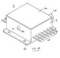
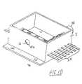
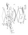
- the heat spreaderserves as an optical platform onto which the quantum cascade laser and the collimating lens are fixedly secured.
- the optical platformis as a rigid platform to maintain the relative positions of the lens and quantum cascade laser which are secured thereto (either directly or indirectly).
- the resulting structurepresents a foot print that is extremely small with a package size (housing size) of approximately 20 cm (height) ⁇ 20 cm (width) ⁇ 20 cm (length) or less.
- the lengthis taken along the optical axis.
- the packages sizemay be any integer or fraction thereof between approximately 1-20 cm for the length dimension combined with any integer or fraction thereof between approximately 1-20 cm in width dimension combined with any integer or fraction thereof between approximately 1-20 cm in the height dimension.
- a preferred footprintis approximately 3 cm (height) ⁇ 4 cm (width) ⁇ 6 cm (length) for the laser package.
Landscapes
- Physics & Mathematics (AREA)
- Optics & Photonics (AREA)
- General Physics & Mathematics (AREA)
- Engineering & Computer Science (AREA)
- Condensed Matter Physics & Semiconductors (AREA)
- Electromagnetism (AREA)
- Nanotechnology (AREA)
- Chemical & Material Sciences (AREA)
- Biophysics (AREA)
- Crystallography & Structural Chemistry (AREA)
- Life Sciences & Earth Sciences (AREA)
- Semiconductor Lasers (AREA)
- Lenses (AREA)
- Optical Modulation, Optical Deflection, Nonlinear Optics, Optical Demodulation, Optical Logic Elements (AREA)
Abstract
Description
Claims (14)
Priority Applications (12)
| Application Number | Priority Date | Filing Date | Title |
|---|---|---|---|
| US11/154,264US7492806B2 (en) | 2005-06-15 | 2005-06-15 | Compact mid-IR laser |
| EP06844137AEP1891716A4 (en) | 2005-06-15 | 2006-06-06 | Compact mid-ir laser |
| PCT/US2006/022033WO2007050134A2 (en) | 2005-06-15 | 2006-06-06 | Compact mid-ir laser |
| US11/525,385US7466734B1 (en) | 2005-06-15 | 2006-09-22 | Compact external cavity mid-IR optical lasers |
| US11/525,384US7535656B2 (en) | 2005-06-15 | 2006-09-22 | Lenses, optical sources, and their couplings |
| US12/354,237US7873094B2 (en) | 2005-06-15 | 2009-01-15 | Compact Mid-IR laser |
| US12/425,306US7796341B2 (en) | 2005-06-15 | 2009-04-16 | Lenses, optical sources, and their couplings |
| US12/697,155US20100132581A1 (en) | 2005-06-15 | 2010-01-29 | Compact mid-ir laser |
| US12/813,679US20100243891A1 (en) | 2005-06-15 | 2010-06-11 | Compact mid-ir laser |
| US12/878,829US8027094B2 (en) | 2005-06-15 | 2010-09-09 | Lenses, optical sources, and their couplings |
| US12/987,830US8050307B2 (en) | 2005-06-15 | 2011-01-10 | Compact mid-IR laser |
| US13/076,358US20110173870A1 (en) | 2005-06-15 | 2011-03-30 | Security device with compact mid-ir laser |
Applications Claiming Priority (1)
| Application Number | Priority Date | Filing Date | Title |
|---|---|---|---|
| US11/154,264US7492806B2 (en) | 2005-06-15 | 2005-06-15 | Compact mid-IR laser |
Related Parent Applications (1)
| Application Number | Title | Priority Date | Filing Date |
|---|---|---|---|
| US12/697,155ContinuationUS20100132581A1 (en) | 2005-06-15 | 2010-01-29 | Compact mid-ir laser |
Related Child Applications (4)
| Application Number | Title | Priority Date | Filing Date |
|---|---|---|---|
| US11/525,384Continuation-In-PartUS7535656B2 (en) | 2005-06-15 | 2006-09-22 | Lenses, optical sources, and their couplings |
| US11/525,385Continuation-In-PartUS7466734B1 (en) | 2005-06-15 | 2006-09-22 | Compact external cavity mid-IR optical lasers |
| US12/354,237ContinuationUS7873094B2 (en) | 2005-06-15 | 2009-01-15 | Compact Mid-IR laser |
| US12/697,155ContinuationUS20100132581A1 (en) | 2005-06-15 | 2010-01-29 | Compact mid-ir laser |
Publications (2)
| Publication Number | Publication Date |
|---|---|
| US20070291804A1 US20070291804A1 (en) | 2007-12-20 |
| US7492806B2true US7492806B2 (en) | 2009-02-17 |
Family
ID=37679005
Family Applications (5)
| Application Number | Title | Priority Date | Filing Date |
|---|---|---|---|
| US11/154,264Expired - LifetimeUS7492806B2 (en) | 2005-06-15 | 2005-06-15 | Compact mid-IR laser |
| US12/354,237Expired - LifetimeUS7873094B2 (en) | 2005-06-15 | 2009-01-15 | Compact Mid-IR laser |
| US12/697,155AbandonedUS20100132581A1 (en) | 2005-06-15 | 2010-01-29 | Compact mid-ir laser |
| US12/987,830Expired - LifetimeUS8050307B2 (en) | 2005-06-15 | 2011-01-10 | Compact mid-IR laser |
| US13/076,358AbandonedUS20110173870A1 (en) | 2005-06-15 | 2011-03-30 | Security device with compact mid-ir laser |
Family Applications After (4)
| Application Number | Title | Priority Date | Filing Date |
|---|---|---|---|
| US12/354,237Expired - LifetimeUS7873094B2 (en) | 2005-06-15 | 2009-01-15 | Compact Mid-IR laser |
| US12/697,155AbandonedUS20100132581A1 (en) | 2005-06-15 | 2010-01-29 | Compact mid-ir laser |
| US12/987,830Expired - LifetimeUS8050307B2 (en) | 2005-06-15 | 2011-01-10 | Compact mid-IR laser |
| US13/076,358AbandonedUS20110173870A1 (en) | 2005-06-15 | 2011-03-30 | Security device with compact mid-ir laser |
Country Status (3)
| Country | Link |
|---|---|
| US (5) | US7492806B2 (en) |
| EP (1) | EP1891716A4 (en) |
| WO (1) | WO2007050134A2 (en) |
Cited By (33)
| Publication number | Priority date | Publication date | Assignee | Title |
|---|---|---|---|---|
| US20080225913A1 (en)* | 2005-10-27 | 2008-09-18 | Limo Patentverwaltung Gmbh & Co. Kg | Semiconductor Laser Device |
| US20090028197A1 (en)* | 2007-07-25 | 2009-01-29 | Daylight Solutions Inc | Fixed wavelength mid infrared laser source with an external cavity |
| US20090213882A1 (en)* | 2008-01-17 | 2009-08-27 | Miles James Weida | Laser source that generates a plurality of alternative wavelength output beams |
| US20090224153A1 (en)* | 2006-08-11 | 2009-09-10 | Lasermax, Inc. | Target Marker having Quantum Cascade Laser for Thermally Marking a Target |
| US20100064777A1 (en)* | 2006-12-07 | 2010-03-18 | Cascade Technologies Limited | Leak detection system and method |
| US20100111122A1 (en)* | 2008-04-29 | 2010-05-06 | Daylight Solutions, Inc. | High output, mid infrared laser source assembly |
| US20100132581A1 (en)* | 2005-06-15 | 2010-06-03 | Timothy Day | Compact mid-ir laser |
| US7796341B2 (en) | 2005-06-15 | 2010-09-14 | Daylight Solutions, Inc. | Lenses, optical sources, and their couplings |
| US20100229448A1 (en)* | 2007-12-14 | 2010-09-16 | Lasermax, Inc. | Removable foregrip with laser sight |
| US20100243891A1 (en)* | 2005-06-15 | 2010-09-30 | Timothy Day | Compact mid-ir laser |
| US20110047851A1 (en)* | 2007-12-14 | 2011-03-03 | Lasermax, Inc. | Removable foregrip with laser sight |
| US20110222566A1 (en)* | 2010-03-15 | 2011-09-15 | Weida Miles J | Laser source that generates a rapidly changing output beam |
| US8335413B2 (en) | 2010-05-14 | 2012-12-18 | Daylight Solutions, Inc. | Optical switch |
| US20130061509A1 (en)* | 2011-09-09 | 2013-03-14 | Lasermax, Inc. | Target marking system |
| US8442081B2 (en) | 2007-03-12 | 2013-05-14 | Daylight Solutions, Inc. | Quantum cascade laser suitable for portable applications |
| US8467430B2 (en) | 2010-09-23 | 2013-06-18 | Daylight Solutions, Inc. | Continuous wavelength tunable laser source with optimum orientation of grating and gain medium |
| US8565275B2 (en) | 2008-04-29 | 2013-10-22 | Daylight Solutions, Inc. | Multi-wavelength high output laser source assembly with precision output beam |
| US8774244B2 (en) | 2009-04-21 | 2014-07-08 | Daylight Solutions, Inc. | Thermal pointer |
| US9042688B2 (en) | 2011-01-26 | 2015-05-26 | Daylight Solutions, Inc. | Multiple port, multiple state optical switch |
| US9059562B2 (en) | 2011-06-23 | 2015-06-16 | Daylight Solutions, Inc. | Control system for directing power to a laser assembly |
| US9077137B2 (en) | 2013-03-08 | 2015-07-07 | Daylight Solutions, Inc. | Laser assembly with package beam pointing registration |
| US9086375B2 (en) | 2008-04-29 | 2015-07-21 | Daylight Solutions, Inc. | Laser source with a large spectral range |
| US9093813B2 (en) | 2011-10-11 | 2015-07-28 | Daylight Solutions, Inc. | Mounting base for a laser system |
| US9147995B2 (en) | 2013-03-15 | 2015-09-29 | Daylight Solutions, Inc. | Rapidly tunable laser source assembly with long stroke grating mover |
| US9225148B2 (en) | 2010-09-23 | 2015-12-29 | Daylight Solutions, Inc. | Laser source assembly with thermal control and mechanically stable mounting |
| US9496674B2 (en) | 2012-08-28 | 2016-11-15 | Daylight Solutions, Inc. | Rapidly tunable laser assembly |
| US20170059279A1 (en)* | 2010-05-04 | 2017-03-02 | Lasermax, Inc. | Encoded signal detection and display |
| US9625671B2 (en) | 2013-10-23 | 2017-04-18 | Lasermax, Inc. | Laser module and system |
| US9791113B2 (en) | 2013-10-23 | 2017-10-17 | Daylight Solutions, Inc. | Light source assembly with multiple, disparate light sources |
| US9859680B2 (en) | 2013-12-17 | 2018-01-02 | Lasermax, Inc. | Shock resistant laser module |
| US10208902B2 (en) | 2013-10-23 | 2019-02-19 | Daylight Solutions, Inc. | Light source assembly with multiple, disparate light sources |
| US11009217B2 (en) | 2013-10-23 | 2021-05-18 | Daylight Solutions, Inc. | Light source assembly with multiple, disparate light sources |
| US20220382017A1 (en)* | 2017-06-14 | 2022-12-01 | Teledyne Flir Commercial Systems, Inc. | Lens systems and methods of manufacture |
Families Citing this family (46)
| Publication number | Priority date | Publication date | Assignee | Title |
|---|---|---|---|---|
| US7466734B1 (en)* | 2005-06-15 | 2008-12-16 | Daylight Solutions, Inc. | Compact external cavity mid-IR optical lasers |
| US9057927B2 (en) | 2005-07-08 | 2015-06-16 | Lockheed Martin Coroporation | High-power multi-function millimeter-wave signal generation using OPO and DFG |
| US7535936B2 (en)* | 2005-08-05 | 2009-05-19 | Daylight Solutions, Inc. | External cavity tunable compact Mid-IR laser |
| US8695266B2 (en) | 2005-12-22 | 2014-04-15 | Larry Moore | Reference beam generating apparatus |
| US7424042B2 (en)* | 2006-09-22 | 2008-09-09 | Daylight Solutions, Inc. | Extended tuning in external cavity quantum cascade lasers |
| US20090159798A1 (en)* | 2007-12-20 | 2009-06-25 | Daylight Solutions, Inc. | Gas imaging system |
| IL190419A0 (en)* | 2008-03-25 | 2008-12-29 | Elta Systems Ltd | A laser aiming and marking device |
| US20100110198A1 (en)* | 2008-04-01 | 2010-05-06 | Daylight Solutions, Inc. | Mid infrared optical illuminator assembly |
| US8627591B2 (en) | 2008-09-05 | 2014-01-14 | Larry Moore | Slot-mounted sighting device |
| US8607495B2 (en) | 2008-10-10 | 2013-12-17 | Larry E. Moore | Light-assisted sighting devices |
| US8312665B2 (en) | 2008-10-10 | 2012-11-20 | P&L Industries, Inc. | Side-mounted lighting device |
| US20110080311A1 (en)* | 2009-10-05 | 2011-04-07 | Michael Pushkarsky | High output laser source assembly with precision output beam |
| US8222822B2 (en) | 2009-10-27 | 2012-07-17 | Tyco Healthcare Group Lp | Inductively-coupled plasma device |
| US20110295140A1 (en)* | 2010-05-28 | 2011-12-01 | Intelliscience Research Llc | Method and Apparatus for Measuring Trace Levels of CO in Human Breath Using Cavity Enhanced, Mid-Infared Absorption Spectroscopy |
| WO2011162776A1 (en)* | 2010-06-25 | 2011-12-29 | Markem-Imaje Corporation | Ingress protected laser |
| US9062932B2 (en) | 2010-10-13 | 2015-06-23 | Lasermax, Inc. | Thermal marking systems and methods of control |
| US8912492B2 (en) | 2010-10-13 | 2014-12-16 | Lasermax, Inc. | Thermal marking systems and methods of control |
| FR2969315B1 (en)* | 2010-12-15 | 2012-12-14 | Univ Reims Champagne Ardenne | METHOD AND DEVICE FOR TRANSMITTING A LASER BEAM IN A CASE |
| US8696150B2 (en) | 2011-01-18 | 2014-04-15 | Larry E. Moore | Low-profile side mounted laser sighting device |
| US9429404B2 (en) | 2011-01-18 | 2016-08-30 | Larry E. Moore | Laser trainer target |
| US10532275B2 (en) | 2012-01-18 | 2020-01-14 | Crimson Trace Corporation | Laser activated moving target |
| GB2499616B (en) | 2012-02-22 | 2017-03-22 | Iti Scotland Ltd | Heterodyne detection system and method |
| US8844189B2 (en) | 2012-12-06 | 2014-09-30 | P&L Industries, Inc. | Sighting device replicating shotgun pattern spread |
| US8822256B1 (en) | 2013-04-04 | 2014-09-02 | Bae Systems Information And Electronic Systems Integration Inc. | Method for fabricating infrared sensors |
| US9297614B2 (en) | 2013-08-13 | 2016-03-29 | Larry E. Moore | Master module light source, retainer and kits |
| US9182194B2 (en) | 2014-02-17 | 2015-11-10 | Larry E. Moore | Front-grip lighting device |
| DE102014102050B4 (en) | 2014-02-18 | 2020-08-13 | Avl Emission Test Systems Gmbh | Device and method for determining the concentration of at least one gas in a sample gas stream by means of infrared absorption spectroscopy |
| US9644826B2 (en) | 2014-04-25 | 2017-05-09 | Larry E. Moore | Weapon with redirected lighting beam |
| US10649497B2 (en)* | 2014-07-23 | 2020-05-12 | Apple Inc. | Adaptive processes for improving integrity of surfaces |
| WO2016014047A1 (en) | 2014-07-23 | 2016-01-28 | Apple Inc. | Adaptive processes for improving integrity of surfaces |
| US10436553B2 (en) | 2014-08-13 | 2019-10-08 | Crimson Trace Corporation | Master module light source and trainer |
| CN107078457A (en)* | 2014-10-28 | 2017-08-18 | 住友电气工业株式会社 | Optical module applying light source, light modulator and wavelength detector and assembly method thereof |
| JP6417199B2 (en)* | 2014-12-08 | 2018-10-31 | 浜松ホトニクス株式会社 | Quantum cascade laser device |
| US10132595B2 (en) | 2015-03-20 | 2018-11-20 | Larry E. Moore | Cross-bow alignment sighter |
| US9829280B1 (en) | 2016-05-26 | 2017-11-28 | Larry E. Moore | Laser activated moving target |
| US10209030B2 (en) | 2016-08-31 | 2019-02-19 | Larry E. Moore | Gun grip |
| US11675078B2 (en)* | 2016-10-06 | 2023-06-13 | GM Global Technology Operations LLC | LiDAR system |
| US10436538B2 (en) | 2017-05-19 | 2019-10-08 | Crimson Trace Corporation | Automatic pistol slide with laser |
| US10622787B2 (en)* | 2018-01-26 | 2020-04-14 | Pranalytica, Inc. | Dual quantum cascade laser micropackage |
| US10209033B1 (en) | 2018-01-30 | 2019-02-19 | Larry E. Moore | Light sighting and training device |
| IL260441A (en)* | 2018-07-05 | 2019-01-31 | The State Of Israel Israel Nat Police | Laser interceptor for soft airborne devices |
| US10804677B2 (en) | 2018-08-21 | 2020-10-13 | Battelle Memorial Institute | Stabilized diode laser |
| JP7568390B2 (en)* | 2019-09-20 | 2024-10-16 | 日亜化学工業株式会社 | Light-emitting device |
| JP7590889B2 (en)* | 2021-02-24 | 2024-11-27 | 浜松ホトニクス株式会社 | External cavity laser module and method for manufacturing the same |
| CN113074640A (en)* | 2021-04-29 | 2021-07-06 | 重庆智能机器人研究院 | Red steel material type detection device, detection robot and detection method |
| CN117253643B (en)* | 2023-09-22 | 2024-03-08 | 之江实验室 | System and method for realizing mesoscopic particle biaxial quantum ground state cooling |
Citations (42)
| Publication number | Priority date | Publication date | Assignee | Title |
|---|---|---|---|---|
| US2684015A (en) | 1950-04-27 | 1954-07-20 | Polaroid Corp | Reflecting mirror optical objective |
| US4656641A (en) | 1985-02-04 | 1987-04-07 | Xerox Corporation | Laser cavity optical system for stabilizing the beam from a phase locked multi-emitter broad emitter laser |
| US5050176A (en)* | 1989-06-19 | 1991-09-17 | Fujitsu Limited | Direct modulation phase-shift-keying system and method |
| US5068867A (en)* | 1989-11-20 | 1991-11-26 | Hughes Aircraft Company | Coupled quantum well strained superlattice structure and optically bistable semiconductor laser incorporating the same |
| US5082339A (en) | 1988-07-11 | 1992-01-21 | Telefunken Electronic Gmbh | Optical read-write head with diffraction grating structure |
| US5082799A (en) | 1990-09-14 | 1992-01-21 | Gte Laboratories Incorporated | Method for fabricating indium phosphide/indium gallium arsenide phosphide buried heterostructure semiconductor lasers |
| US5140599A (en) | 1990-08-01 | 1992-08-18 | Hewlett-Packard Company | Optical oscillator sweeper |
| US5172390A (en)* | 1989-04-20 | 1992-12-15 | Massachusetts Institute Of Technology | Pre-aligned diode laser for external cavity operation |
| US5181214A (en)* | 1991-11-18 | 1993-01-19 | Harmonic Lightwaves, Inc. | Temperature stable solid-state laser package |
| US5331651A (en) | 1992-01-24 | 1994-07-19 | Hewlett-Packard Company | Method and apparatus for adjusting the wavelength in an optical device and laser using the method |
| US5457709A (en) | 1994-04-04 | 1995-10-10 | At&T Ipm Corp. | Unipolar semiconductor laser |
| US5537432A (en) | 1993-01-07 | 1996-07-16 | Sdl, Inc. | Wavelength-stabilized, high power semiconductor laser |
| US5662819A (en)* | 1994-02-10 | 1997-09-02 | Sony Corporation | Plasma processing method with controlled ion/radical ratio |
| US5752100A (en) | 1996-01-26 | 1998-05-12 | Eastman Kodak Company | Driver circuit for a camera autofocus laser diode with provision for fault protection |
| US6243404B1 (en) | 1999-01-25 | 2001-06-05 | Lucent Technologies, Inc. | Laser module with adjustable operating temperature range |
| US20010036210A1 (en)* | 1998-12-31 | 2001-11-01 | Nokia Networks Oy | Method and a coupling to change the wavelength of an optical transmitter in a system using wavelength division multiplexing |
| US6326646B1 (en)* | 1999-11-24 | 2001-12-04 | Lucent Technologies, Inc. | Mounting technology for intersubband light emitters |
| US20020090013A1 (en)* | 2001-01-09 | 2002-07-11 | Murry Stefan J. | VCSEL assembly with edge-receiving optical devices |
| US20020150133A1 (en) | 1999-02-04 | 2002-10-17 | Takeshi Aikiyo | Mounting structure for semiconductor laser module |
| US6483978B1 (en) | 2001-06-08 | 2002-11-19 | Photon-X, Inc. | Compact optical amplifier module |
| US20020176473A1 (en) | 2001-05-23 | 2002-11-28 | Aram Mooradian | Wavelength selectable, controlled chirp, semiconductor laser |
| US20030043877A1 (en) | 2001-09-04 | 2003-03-06 | Ron Kaspi | Multiple wavelength broad bandwidth optically pumped semiconductor laser |
| US20030095346A1 (en)* | 2001-10-31 | 2003-05-22 | The Furukawa Electric Co., Ltd. | Optical module |
| US6575641B2 (en) | 2000-11-13 | 2003-06-10 | Sumitomo Electric Industries, Ltd. | Laser diode module |
| US6636539B2 (en) | 2001-05-25 | 2003-10-21 | Novalux, Inc. | Method and apparatus for controlling thermal variations in an optical device |
| US20030198274A1 (en)* | 2002-04-20 | 2003-10-23 | Lucchetti Richard L. | Laser-based jaw setting device |
| US6652452B1 (en)* | 1999-10-25 | 2003-11-25 | Advanced Medical Electronics Corporation | Infrared endoscope with sensor array at the distal tip |
| US20040013154A1 (en) | 2002-07-16 | 2004-01-22 | Applied Optoelectronics, Inc. | Optically-pumped multiple-quantum well active region with improved distribution of optical pumping power |
| US6782162B2 (en) | 2001-08-06 | 2004-08-24 | Nippon Sheet Glass Co., Ltd. | Optical module and method for assembling the same |
| US20040208602A1 (en) | 2001-12-01 | 2004-10-21 | James Plante | Free space optical communications link tolerant of atmospheric interference |
| US20040228371A1 (en) | 2003-04-09 | 2004-11-18 | James Kolodzey | Terahertz frequency radiation sources and detectors based on group IV materials and method of manufacture |
| US20040238811A1 (en) | 2002-06-28 | 2004-12-02 | Takao Nakamura | Semiconductor light-emitting device |
| US6856717B2 (en) | 2003-03-24 | 2005-02-15 | Hymite A/S | Package with a light emitting device |
| US20050199869A1 (en)* | 2004-02-05 | 2005-09-15 | Zhisheng Shi | Orientated group IV-VI semiconductor structure, and method for making and using the same |
| US20050213627A1 (en) | 2004-02-20 | 2005-09-29 | Humboldt-Universtaet Zu Berlin | Quantum cascade laser structure |
| US20050237524A1 (en) | 2004-03-01 | 2005-10-27 | National Institute Of Adv. Industrial Sci. & Tech. | Device for detecting emission light of micro-object |
| US20060056466A1 (en) | 2004-08-19 | 2006-03-16 | Gregory Belenky | Semiconductor light source with electrically tunable emission wavelength |
| US7032431B2 (en) | 2003-06-13 | 2006-04-25 | Baum Marc A | Non-invasive, miniature, breath monitoring apparatus |
| US7061022B1 (en) | 2003-08-26 | 2006-06-13 | United States Of America As Represented By The Secretary Of The Army | Lateral heat spreading layers for epi-side up ridge waveguide semiconductor lasers |
| US20070030865A1 (en) | 2005-08-05 | 2007-02-08 | Daylight Solutions | External cavity tunable compact mid-IR laser |
| US20070291804A1 (en) | 2005-06-15 | 2007-12-20 | Timothy Day | Compact mid-IR laser |
| US20080075133A1 (en) | 2006-09-22 | 2008-03-27 | Daylight Solutions Inc. | Extended tuning in external cavity quantum cascade lasers |
Family Cites Families (126)
| Publication number | Priority date | Publication date | Assignee | Title |
|---|---|---|---|---|
| US199869A (en)* | 1878-01-29 | Improvement in duplex telegraphs | ||
| US95346A (en)* | 1869-09-28 | hitchcock | ||
| US2685015A (en)* | 1953-03-31 | 1954-07-27 | Paul G Weiller | Resistance thermometer element |
| US3782832A (en)* | 1973-04-12 | 1974-01-01 | Us Army | Method of boresight alignment of a weapon |
| JPS5587107A (en) | 1978-12-23 | 1980-07-01 | Fujitsu Ltd | Photo switch |
| US4266873A (en)* | 1979-08-20 | 1981-05-12 | The United States Of America As Represented By The Secretary Of The Army | Collinear aiming light image viewer |
| US4555627A (en) | 1983-04-05 | 1985-11-26 | The United States Of America As Represented By The United States Department Of Energy | Backscatter absorption gas imaging system |
| US4470662A (en)* | 1983-04-07 | 1984-09-11 | Mid-West Instrument | Rotary optic switch |
| DE3508193C2 (en)* | 1985-03-08 | 1987-03-26 | Preussag Ag Metall, 3380 Goslar | Device for detecting fluorescent substances on the earth's surface |
| US4737028A (en)* | 1986-04-07 | 1988-04-12 | The United States Of America As Represented By The Secretary Of The Army | Target loop active boresighting device |
| US4852956A (en)* | 1986-12-15 | 1989-08-01 | Holotek Ltd. | Hologan scanner system |
| AU598367B2 (en)* | 1987-05-08 | 1990-06-21 | Broken Hill Proprietary Company Limited, The | Sensing of methane |
| US4796266A (en) | 1987-12-21 | 1989-01-03 | Bell Communications Research, Inc. | Laser driver circuit with dynamic bias |
| US4772789A (en)* | 1987-12-28 | 1988-09-20 | Rockwell International Corporation | Leak imaging using differential absorption |
| SE462934B (en)* | 1989-05-19 | 1990-09-17 | Opsis Ab Ideon | DEVICE FOR TRANSMISSION AND RECEIVING LIGHTS |
| US5005934A (en)* | 1989-07-11 | 1991-04-09 | Galileo Electro-Optics Corporation | Fiber optics channel selection device |
| JPH0724322B2 (en)* | 1989-07-17 | 1995-03-15 | 松下電器産業株式会社 | Optical feedback type light emitting device |
| DE4003932A1 (en)* | 1990-02-09 | 1991-08-14 | Messerschmitt Boelkow Blohm | METHOD FOR VISOR ADJUSTMENT IN WEAPON SYSTEMS |
| US5056097A (en)* | 1990-03-02 | 1991-10-08 | Meyers Brad E | Target illuminators and systems employing same |
| US5064988A (en) | 1990-04-19 | 1991-11-12 | Havis-Shields Equipment Corporation | Laser light attachment for firearms |
| JP3198292B2 (en) | 1990-06-06 | 2001-08-13 | ケイオウエル オウエイチアール コーポレーション | Optical fiber system |
| US5264368A (en) | 1990-10-10 | 1993-11-23 | Boston Advanced Technologies, Inc. | Hydrocarbon leak sensor |
| IL96869A (en)* | 1991-01-02 | 1994-04-12 | Israel State | Method and system for aiming a small caliber weapon |
| SE468337B (en) | 1991-05-08 | 1992-12-14 | Radians Innova Ab | SETTING AND ADJUSTING A LASER AND LASER DEVICE WHICH IMPLEMENTS THE SET |
| US5161408A (en) | 1991-08-26 | 1992-11-10 | Mcrae Thomas G | Photo-acoustic leak detection system and method |
| US5430293A (en)* | 1991-10-08 | 1995-07-04 | Osaka Gas Co., Ltd. | Gas visualizing apparatus and method for detecting gas leakage from tanks or piping |
| US5225679A (en)* | 1992-01-24 | 1993-07-06 | Boston Advanced Technologies, Inc. | Methods and apparatus for determining hydrocarbon fuel properties |
| US5355609A (en)* | 1992-12-04 | 1994-10-18 | Schenke Reynold A | Laser beam sighting apparatus with a selectively adjustable beam width |
| DE4321644A1 (en)* | 1993-06-30 | 1995-01-12 | Nord Systemtechnik | Device for detecting leaks in components |
| US5481631A (en) | 1994-02-25 | 1996-01-02 | The Perkin-Elmer Corp. | Optical switching apparatus with retroreflector |
| JPH07240558A (en)* | 1994-02-28 | 1995-09-12 | Ando Electric Co Ltd | Light source of tunable semiconductor laser |
| US5410815A (en) | 1994-04-29 | 1995-05-02 | Cubic Defense Systems, Inc. | Automatic player identification small arms laser alignment system |
| US5656813A (en)* | 1995-04-04 | 1997-08-12 | Gmd Systems, Inc. | Apparatus for imaging gas |
| US5751830A (en) | 1995-05-24 | 1998-05-12 | Lockheed Martin Energy Systems, Inc. | Method and apparatus for coherent imaging of infrared energy |
| US5685636A (en) | 1995-08-23 | 1997-11-11 | Science And Engineering Associates, Inc. | Eye safe laser security device |
| US5671561A (en)* | 1995-11-14 | 1997-09-30 | Emerging Technologies, Inc. | Modular, combination laser and electronic aiming system |
| JPH09260753A (en)* | 1996-03-25 | 1997-10-03 | Ando Electric Co Ltd | External resonator-type variable wavelength light source |
| IL139982A (en)* | 1996-04-01 | 2004-07-25 | Lockheed Corp | Combined laser/flir optics system |
| US5854422A (en) | 1996-07-10 | 1998-12-29 | K-Line Industries, Inc. | Ultrasonic detector |
| US5866073A (en)* | 1997-02-28 | 1999-02-02 | The United States Of America As Represented By The Secretary Of The Army | Detector of halogenated compounds based on laser photofragmentation/fragment stimulated emission |
| US5834632A (en) | 1997-03-27 | 1998-11-10 | United Technologies Corporation | Photo-acoustic leak detector with multiple beams |
| US5780724A (en)* | 1997-03-27 | 1998-07-14 | United Technologies Corp | Photo-acoustic leak detector with improved signal-to-noise response |
| US5901168A (en) | 1997-05-07 | 1999-05-04 | Lucent Technologies Inc. | Article comprising an improved QC laser |
| JPH10341057A (en) | 1997-06-06 | 1998-12-22 | Ando Electric Co Ltd | External resonator type wavelength-variable semiconductor laser optical source and wavelength variable method therefor |
| US6192064B1 (en)* | 1997-07-01 | 2001-02-20 | Cymer, Inc. | Narrow band laser with fine wavelength control |
| US6142650A (en)* | 1997-07-10 | 2000-11-07 | Brown; David C. | Laser flashlight |
| US5892617A (en)* | 1997-07-28 | 1999-04-06 | Wallace; Robert E. | Multi-function day/night observation, ranging, and sighting device and method of its operation |
| US6134257A (en) | 1998-04-21 | 2000-10-17 | Lucent Technologies Inc. | Solid state laser for operation in librational modes |
| US6157033A (en) | 1998-05-18 | 2000-12-05 | Power Distribution Services, Inc. | Leak detection system |
| US6089076A (en)* | 1998-09-18 | 2000-07-18 | United Technologies Corporation | System to control the power of a beam |
| US6154307A (en) | 1998-09-18 | 2000-11-28 | United Technologies Corporation | Method and apparatus to diffract multiple beams |
| AU3204900A (en)* | 1999-02-19 | 2000-09-04 | Radians Innova Ab | Device and method for tuning the wavelength of the light in an external cavity laser |
| US6714564B1 (en)* | 1999-08-23 | 2004-03-30 | B. E. Meyers & Co., Inc. | Dual function single laser |
| WO2001026192A1 (en)* | 1999-10-07 | 2001-04-12 | Maxion Technologies, Inc. | Parallel cascade quantum well light emitting device |
| SE9904836L (en)* | 1999-12-28 | 2001-06-29 | Jonas Sandsten | Quantitative imaging of gas emissions using optical technology |
| US6363648B1 (en)* | 2000-01-27 | 2002-04-02 | William H. Grube | Laser aiming light for firearms |
| US6400744B1 (en) | 2000-02-25 | 2002-06-04 | Lucent Technologies, Inc. | Apparatus comprising a quantum cascade laser having improved distributed feedback for single-mode operation |
| DE60115445T2 (en)* | 2000-06-09 | 2006-09-07 | L-3 Communications Corporation | FIREARM LASER EXERCISE SYSTEM AND METHOD FOR FIRE FIGURINE IMPROVEMENT WITH DIFFERENT OBJECTIVES AND VISUAL RE-COUPLING OF SIMULATED STOREY LOCATIONS |
| US7345277B2 (en) | 2000-08-09 | 2008-03-18 | Evan Zhang | Image intensifier and LWIR fusion/combination system |
| US6646799B1 (en) | 2000-08-30 | 2003-11-11 | Science Applications International Corporation | System and method for combining multiple energy bands to improve scene viewing |
| US6741066B1 (en) | 2000-09-21 | 2004-05-25 | O2Micro International Limited | Power management for battery powered appliances |
| US6690472B2 (en)* | 2000-09-28 | 2004-02-10 | Sandia National Laboratories | Pulsed laser linescanner for a backscatter absorption gas imaging system |
| US6470036B1 (en) | 2000-11-03 | 2002-10-22 | Cidra Corporation | Tunable external cavity semiconductor laser incorporating a tunable bragg grating |
| JP2002164613A (en)* | 2000-11-27 | 2002-06-07 | Sharp Corp | Semiconductor laser device |
| US6636653B2 (en)* | 2001-02-02 | 2003-10-21 | Teravicta Technologies, Inc. | Integrated optical micro-electromechanical systems and methods of fabricating and operating the same |
| JP2002280659A (en)* | 2001-03-16 | 2002-09-27 | Furukawa Electric Co Ltd:The | Light source consisting of laser diode module |
| US7505119B2 (en)* | 2001-04-13 | 2009-03-17 | Optical Air Data Systems, Llc | Multi-function optical system and assembly |
| JPWO2003005509A1 (en)* | 2001-07-02 | 2004-10-28 | 古河電気工業株式会社 | Semiconductor laser module, optical amplifier, and method of manufacturing semiconductor laser module |
| US6798358B2 (en) | 2001-07-03 | 2004-09-28 | Nortel Networks Limited | Location-based content delivery |
| US6914917B2 (en)* | 2001-07-24 | 2005-07-05 | Southwest Sciences Incorporated | Discrete wavelength-locked external cavity laser |
| US6526688B1 (en)* | 2001-08-13 | 2003-03-04 | Lewis Danielson | Apparatus and method for actuating a weapon accessory by a laser sighting beam |
| US6608847B2 (en)* | 2001-09-28 | 2003-08-19 | New Focus, Inc. | Tunable laser with suppression of spontaneous emission |
| US7248611B2 (en)* | 2001-10-31 | 2007-07-24 | William Marsh Rice University | Frequency scanning pulsed laser having synchronously set subthreshold current |
| US6903343B2 (en)* | 2001-11-20 | 2005-06-07 | Lockheed Martin Corporation | Lightweight laser designator ranger flir optics |
| US6862301B2 (en)* | 2001-12-31 | 2005-03-01 | Finisar Corporation | Tunable laser assembly |
| DE10205310B4 (en) | 2002-02-08 | 2010-04-15 | Fraunhofer-Gesellschaft zur Förderung der angewandten Forschung e.V. | A method for generating the effect of a broadband incoherent LED-like light source and use of such a method in a gas measuring device and in a lighting device |
| US6765663B2 (en)* | 2002-03-14 | 2004-07-20 | Raytheon Company | Efficient multiple emitter boresight reference source |
| JP2006507478A (en)* | 2002-05-22 | 2006-03-02 | ファースト レスポンダー システムズ アンド テクノロジー,エル エル シー | Remote chemical identification processing system |
| US6866089B2 (en)* | 2002-07-02 | 2005-03-15 | Carrier Corporation | Leak detection with thermal imaging |
| US6975402B2 (en)* | 2002-11-19 | 2005-12-13 | Sandia National Laboratories | Tunable light source for use in photoacoustic spectrometers |
| US6769347B1 (en)* | 2002-11-26 | 2004-08-03 | Recon/Optical, Inc. | Dual elevation weapon station and method of use |
| US7031353B2 (en)* | 2003-02-25 | 2006-04-18 | Clifford Jr George M | Apparatus and method for adjusting external-cavity lasers |
| US20040264523A1 (en) | 2003-06-30 | 2004-12-30 | Posamentier Joshua D | Temperature compensation circuit to maintain ratio of monitor photodiode current to fiber coupled light in a laser |
| US7358498B2 (en) | 2003-08-04 | 2008-04-15 | Technest Holdings, Inc. | System and a method for a smart surveillance system |
| US7189970B2 (en) | 2003-08-29 | 2007-03-13 | Power Diagnostic Technologies Ltd. | Imaging of fugitive gas leaks |
| US7151787B2 (en) | 2003-09-10 | 2006-12-19 | Sandia National Laboratories | Backscatter absorption gas imaging systems and light sources therefore |
| DE20317904U1 (en)* | 2003-11-19 | 2005-03-31 | Sacher Joachim | Laser diode array with external resonator |
| US6822742B1 (en)* | 2003-12-19 | 2004-11-23 | Eastman Kodak Company | System and method for remote quantitative detection of fluid leaks from a natural gas or oil pipeline |
| US7490430B2 (en)* | 2004-03-10 | 2009-02-17 | Raytheon Company | Device with multiple sights for respective different munitions |
| WO2005115737A2 (en) | 2004-03-22 | 2005-12-08 | Quantaspec Inc. | System and method for detecting and identifying an analyte |
| JP2005317819A (en) | 2004-04-30 | 2005-11-10 | Sony Corp | Laser system |
| US7161787B2 (en)* | 2004-05-04 | 2007-01-09 | Millipore Corporation | Low power solenoid driver circuit |
| US7325354B2 (en)* | 2004-05-06 | 2008-02-05 | Insight Technology, Inc. | Weapon aiming device |
| US20070008999A1 (en)* | 2004-06-07 | 2007-01-11 | Maxion Technologies, Inc. | Broadened waveguide for interband cascade lasers |
| ATE504020T1 (en) | 2004-07-15 | 2011-04-15 | Polatis Ltd | OPTICAL SWITCH |
| US7265842B2 (en) | 2004-10-14 | 2007-09-04 | Picarro, Inc. | Method for detecting a gaseous analyte present as a minor constituent in an admixture |
| US7051469B1 (en)* | 2004-12-14 | 2006-05-30 | Omnitech Partners | Night sight for use with a telescopic sight |
| US8129684B2 (en) | 2005-03-22 | 2012-03-06 | Coherent, Inc. | Detection of hidden objects by terahertz heterodyne laser imaging |
| US20060262316A1 (en) | 2005-05-20 | 2006-11-23 | Baney Douglas M | System and method for interferometric laser photoacoustic spectroscopy |
| US7474685B2 (en) | 2005-05-24 | 2009-01-06 | Itt Manufacturing Enterprises, Inc. | Multi-line tunable laser system |
| US7535656B2 (en) | 2005-06-15 | 2009-05-19 | Daylight Solutions, Inc. | Lenses, optical sources, and their couplings |
| US20100243891A1 (en)* | 2005-06-15 | 2010-09-30 | Timothy Day | Compact mid-ir laser |
| US7466734B1 (en) | 2005-06-15 | 2008-12-16 | Daylight Solutions, Inc. | Compact external cavity mid-IR optical lasers |
| US7733924B2 (en)* | 2005-08-15 | 2010-06-08 | William Marsh Rice University | Piezo activated mode tracking system for widely tunable mode-hop-free external cavity mid-IR semiconductor lasers |
| GB0518732D0 (en)* | 2005-09-14 | 2005-10-19 | Polatis Ltd | Latching switch improvements |
| US7325318B2 (en)* | 2005-09-22 | 2008-02-05 | Cubic Corporation | Compact multifunction sight |
| US7755041B2 (en) | 2005-11-15 | 2010-07-13 | University Of South Florida | Optical and laser differential absorption remote detection of TATP peroxide based explosives |
| US7753549B2 (en)* | 2006-02-02 | 2010-07-13 | L-3 Insight Technology Incorporated | Weapon aiming device |
| US20070209268A1 (en)* | 2006-03-09 | 2007-09-13 | Santa Barbara Infrared, Inc. | Laser rangefinder sighting apparatus and method |
| TWM296364U (en)* | 2006-03-20 | 2006-08-21 | Asia Optical Co Inc | Firearms aiming and photographing compound apparatus |
| US7903704B2 (en)* | 2006-06-23 | 2011-03-08 | Pranalytica, Inc. | Tunable quantum cascade lasers and photoacoustic detection of trace gases, TNT, TATP and precursors acetone and hydrogen peroxide |
| US7732767B2 (en)* | 2006-08-11 | 2010-06-08 | Lasermax, Inc. | Target marker having quantum cascade laser for thermally marking a target |
| US7609738B2 (en)* | 2006-10-30 | 2009-10-27 | Maxion Technologies, Inc. | Multiple phonon resonance quantum cascade lasers |
| US7429734B1 (en)* | 2006-11-29 | 2008-09-30 | Aculight Corporation | System and method for aircraft infrared countermeasures to missiles |
| US7920608B2 (en)* | 2007-03-12 | 2011-04-05 | Daylight Solutions, Inc. | Quantum cascade laser suitable for portable applications |
| US8659664B2 (en)* | 2007-03-23 | 2014-02-25 | Flir Systems, Inc. | Thermography camera configured for leak detection |
| US8115994B2 (en) | 2007-07-10 | 2012-02-14 | Lockheed Martin Corporation | Scanning wide field telescope and method |
| US7818911B2 (en) | 2007-10-26 | 2010-10-26 | Lasermax, Inc. | Target marking system having a gas laser assembly and a thermal imager |
| US20100229448A1 (en)* | 2007-12-14 | 2010-09-16 | Lasermax, Inc. | Removable foregrip with laser sight |
| US20090159798A1 (en)* | 2007-12-20 | 2009-06-25 | Daylight Solutions, Inc. | Gas imaging system |
| US7848382B2 (en) | 2008-01-17 | 2010-12-07 | Daylight Solutions, Inc. | Laser source that generates a plurality of alternative wavelength output beams |
| US7936511B2 (en)* | 2008-02-19 | 2011-05-03 | B.E. Meyers & Co., Inc | Single laser illuminating and pointing systems |
| US8014430B2 (en)* | 2008-02-27 | 2011-09-06 | President And Fellows Of Harvard College | Quantum cascade laser |
| US20090219961A1 (en)* | 2008-02-28 | 2009-09-03 | B.E. Meyers & Co., Inc. | Laser Systems and Methods Having Auto-Ranging and Control Capability |
| US20100110198A1 (en)* | 2008-04-01 | 2010-05-06 | Daylight Solutions, Inc. | Mid infrared optical illuminator assembly |
| US7733925B2 (en) | 2008-07-07 | 2010-06-08 | Daylight Solutions, Inc. | Continuous wavelength tunable laser source with optimum positioning of pivot axis for grating |
- 2005
- 2005-06-15USUS11/154,264patent/US7492806B2/ennot_activeExpired - Lifetime
- 2006
- 2006-06-06EPEP06844137Apatent/EP1891716A4/ennot_activeWithdrawn
- 2006-06-06WOPCT/US2006/022033patent/WO2007050134A2/enactiveApplication Filing
- 2009
- 2009-01-15USUS12/354,237patent/US7873094B2/ennot_activeExpired - Lifetime
- 2010
- 2010-01-29USUS12/697,155patent/US20100132581A1/ennot_activeAbandoned
- 2011
- 2011-01-10USUS12/987,830patent/US8050307B2/ennot_activeExpired - Lifetime
- 2011-03-30USUS13/076,358patent/US20110173870A1/ennot_activeAbandoned
Patent Citations (44)
| Publication number | Priority date | Publication date | Assignee | Title |
|---|---|---|---|---|
| US2684015A (en) | 1950-04-27 | 1954-07-20 | Polaroid Corp | Reflecting mirror optical objective |
| US4656641A (en) | 1985-02-04 | 1987-04-07 | Xerox Corporation | Laser cavity optical system for stabilizing the beam from a phase locked multi-emitter broad emitter laser |
| US5082339A (en) | 1988-07-11 | 1992-01-21 | Telefunken Electronic Gmbh | Optical read-write head with diffraction grating structure |
| US5172390A (en)* | 1989-04-20 | 1992-12-15 | Massachusetts Institute Of Technology | Pre-aligned diode laser for external cavity operation |
| US5050176A (en)* | 1989-06-19 | 1991-09-17 | Fujitsu Limited | Direct modulation phase-shift-keying system and method |
| US5068867A (en)* | 1989-11-20 | 1991-11-26 | Hughes Aircraft Company | Coupled quantum well strained superlattice structure and optically bistable semiconductor laser incorporating the same |
| US5140599A (en) | 1990-08-01 | 1992-08-18 | Hewlett-Packard Company | Optical oscillator sweeper |
| US5082799A (en) | 1990-09-14 | 1992-01-21 | Gte Laboratories Incorporated | Method for fabricating indium phosphide/indium gallium arsenide phosphide buried heterostructure semiconductor lasers |
| US5181214A (en)* | 1991-11-18 | 1993-01-19 | Harmonic Lightwaves, Inc. | Temperature stable solid-state laser package |
| US5331651A (en) | 1992-01-24 | 1994-07-19 | Hewlett-Packard Company | Method and apparatus for adjusting the wavelength in an optical device and laser using the method |
| US5537432A (en) | 1993-01-07 | 1996-07-16 | Sdl, Inc. | Wavelength-stabilized, high power semiconductor laser |
| US5662819A (en)* | 1994-02-10 | 1997-09-02 | Sony Corporation | Plasma processing method with controlled ion/radical ratio |
| US5457709A (en) | 1994-04-04 | 1995-10-10 | At&T Ipm Corp. | Unipolar semiconductor laser |
| US5752100A (en) | 1996-01-26 | 1998-05-12 | Eastman Kodak Company | Driver circuit for a camera autofocus laser diode with provision for fault protection |
| US20010036210A1 (en)* | 1998-12-31 | 2001-11-01 | Nokia Networks Oy | Method and a coupling to change the wavelength of an optical transmitter in a system using wavelength division multiplexing |
| US6243404B1 (en) | 1999-01-25 | 2001-06-05 | Lucent Technologies, Inc. | Laser module with adjustable operating temperature range |
| US20020150133A1 (en) | 1999-02-04 | 2002-10-17 | Takeshi Aikiyo | Mounting structure for semiconductor laser module |
| US6652452B1 (en)* | 1999-10-25 | 2003-11-25 | Advanced Medical Electronics Corporation | Infrared endoscope with sensor array at the distal tip |
| US6326646B1 (en)* | 1999-11-24 | 2001-12-04 | Lucent Technologies, Inc. | Mounting technology for intersubband light emitters |
| US6575641B2 (en) | 2000-11-13 | 2003-06-10 | Sumitomo Electric Industries, Ltd. | Laser diode module |
| US20020090013A1 (en)* | 2001-01-09 | 2002-07-11 | Murry Stefan J. | VCSEL assembly with edge-receiving optical devices |
| US20020176473A1 (en) | 2001-05-23 | 2002-11-28 | Aram Mooradian | Wavelength selectable, controlled chirp, semiconductor laser |
| US6636539B2 (en) | 2001-05-25 | 2003-10-21 | Novalux, Inc. | Method and apparatus for controlling thermal variations in an optical device |
| US6483978B1 (en) | 2001-06-08 | 2002-11-19 | Photon-X, Inc. | Compact optical amplifier module |
| US6782162B2 (en) | 2001-08-06 | 2004-08-24 | Nippon Sheet Glass Co., Ltd. | Optical module and method for assembling the same |
| US6553045B2 (en) | 2001-09-04 | 2003-04-22 | The United States Of America As Represented By The Secretary Of The Air Force | Multiple wavelength broad bandwidth optically pumped semiconductor laser |
| US20030043877A1 (en) | 2001-09-04 | 2003-03-06 | Ron Kaspi | Multiple wavelength broad bandwidth optically pumped semiconductor laser |
| US20030095346A1 (en)* | 2001-10-31 | 2003-05-22 | The Furukawa Electric Co., Ltd. | Optical module |
| US20040208602A1 (en) | 2001-12-01 | 2004-10-21 | James Plante | Free space optical communications link tolerant of atmospheric interference |
| US20030198274A1 (en)* | 2002-04-20 | 2003-10-23 | Lucchetti Richard L. | Laser-based jaw setting device |
| US20040238811A1 (en) | 2002-06-28 | 2004-12-02 | Takao Nakamura | Semiconductor light-emitting device |
| US6859481B2 (en) | 2002-07-16 | 2005-02-22 | Applied Optoelectronics, Inc. | Optically-pumped multiple-quantum well active region with improved distribution of optical pumping power |
| US20040013154A1 (en) | 2002-07-16 | 2004-01-22 | Applied Optoelectronics, Inc. | Optically-pumped multiple-quantum well active region with improved distribution of optical pumping power |
| US6856717B2 (en) | 2003-03-24 | 2005-02-15 | Hymite A/S | Package with a light emitting device |
| US20040228371A1 (en) | 2003-04-09 | 2004-11-18 | James Kolodzey | Terahertz frequency radiation sources and detectors based on group IV materials and method of manufacture |
| US7032431B2 (en) | 2003-06-13 | 2006-04-25 | Baum Marc A | Non-invasive, miniature, breath monitoring apparatus |
| US7061022B1 (en) | 2003-08-26 | 2006-06-13 | United States Of America As Represented By The Secretary Of The Army | Lateral heat spreading layers for epi-side up ridge waveguide semiconductor lasers |
| US20050199869A1 (en)* | 2004-02-05 | 2005-09-15 | Zhisheng Shi | Orientated group IV-VI semiconductor structure, and method for making and using the same |
| US20050213627A1 (en) | 2004-02-20 | 2005-09-29 | Humboldt-Universtaet Zu Berlin | Quantum cascade laser structure |
| US20050237524A1 (en) | 2004-03-01 | 2005-10-27 | National Institute Of Adv. Industrial Sci. & Tech. | Device for detecting emission light of micro-object |
| US20060056466A1 (en) | 2004-08-19 | 2006-03-16 | Gregory Belenky | Semiconductor light source with electrically tunable emission wavelength |
| US20070291804A1 (en) | 2005-06-15 | 2007-12-20 | Timothy Day | Compact mid-IR laser |
| US20070030865A1 (en) | 2005-08-05 | 2007-02-08 | Daylight Solutions | External cavity tunable compact mid-IR laser |
| US20080075133A1 (en) | 2006-09-22 | 2008-03-27 | Daylight Solutions Inc. | Extended tuning in external cavity quantum cascade lasers |
Non-Patent Citations (29)
| Title |
|---|
| AIAA 2002-0824 Measurments of Trace Pollutants in Combustion Flows Using Room-Temperatur, Mid-IR Quantum Cascade Lasers.-S Wehe, D Sonnenfroh, M Allen (Physical Sciences Inc.) C Gmachl and F Capasso ( Bell Laboratories, Lucent Technologies)-Meeting and Exhibit Jan. 14-17, 2002-cover and pp. 1-7. |
| Cavity Enhancing Sensors using QC Lasers-infrared.phl.gov/enhanced.sensors.htm-pp. 1-6. |
| Corrie David Farmer, "Fab and Eval. of QCL's", Sep. 2000, Faculty of Engineering, University of Glasgow, Glasgow, UK. |
| External-cavity quantum-cascade lasers-www.unine.ch/phys/meso/EC/ED.html pp. 1-4. |
| FM Spectroscopy With Tunable Diode Lasers-Application Note 7-New Focus Copyright 2001-pp. 1-10. |
| Frequency Modulation Spectroscopy-J Andrews and P Dallin-www.spectroscopyeurope.com-pp. 24-26. |
| Frequency stabilization of diode lasers-Santa Chawla-National Physical Laboratoriy-www.ias.ac.in/currsci/jan25/articles41.htm-pp. 1-17. |
| Gaetano Scamarcio et al., Micro-probe characterization of QCLs correlation with optical performance, APL 78, 1177 & APL 78, 2095 (2001), APL 2002, APL 2004, University of Bari, Bari Italy. |
| Gaetano Scamarcio, Mid-IR and THz Quantum Cascade Lasers, 2005, Physics Dept., University of Bari, Bari Italy. |
| J. Faist, THz and Mid-IR Quantum cascade lasers, QM in space, Chatillon, Mar. 31, Science 2002, University of Neuchatel, EU Projects Answer/Teranova; Agilent, Funding Swiss National Science Foundation. |
| J.M. Hensley et al., Demonstration of an External Cavity Terahertz Quantum Cascade Laser, Copyright 2005, Optical Society of America, Washington, DC 20036. |
| Joel M. Hensley, Recent Updates in QCL-based Sensing Applications, Sep. 5-10, 2006, Physical Sciences, Inc., Andover, MA, 2nd International Workshop on Quantum Cascade Lasers, Ostuni, Italy. |
| L. Hildebrandt et al., Quantum cascade external cavity and DFB laser systems in the mid-infrared spectral range: devices and applications, 2004, Marburg Germany. |
| MOEMS Tuning Element for a Littrow Exernal Cavity Laser-Journal of Microelectromechanical Systems, vol. 12, No. 6 Dec. 2003-RA Syms-A Lohmann-pp. 921-928. |
| Peltier Coolers-V Rudometov-E Rudometov-Vontage The Broadband Phone Company-www.digit-life.com/article/peltiercollers/ pp. 1-11. |
| Precision MEMS Flexure mount for a Littman tunable external cavity laser-W Huang, RRA Syms, J. Stagg and A. A Lohmann-IEE Prc-Sci Meas. Technol vol. 151, No. 2 Mar. 2004-pp. 67-75. |
| Pushkarsky, M. et al.; "Sub-parts-per-billion level detection of NO2 using room temp. QCLs"; May 2006. |
| Quantum cascade external cavity and DFB laser systems in the mid-infrared spectral range; devices and applications-L Hildebrandt, S Stry, R Knispel, JR Sacher, T Beyer, M Braun, A Lambrecht, T Gensty, W Elsaber, Ch. Mann and F. Fuchs-2 pages. |
| Richard Maulini et al., Broadly tunable external cavity quantum-cascade lasers, 2005, University of Neuchatel, Neuchatel Switzerland. |
| Room-temperature mid-infrared laser sensor for trace gas detection-T Topfer, KP Petrov, Y Mine, D Jundt, RF Curl, and FK Tittel-Applied Optices/ vol. 36. No. 30-Oct. 20, 1997 pp. 8042-8049. |
| S. Blaser et al., Alpes Lasers, Room-temperature continuous-wave single-mode quantum cascade lasers, Photonics West 2006, Novel In-Plane Semiconductors V:Quantum Cascade Lasers:6133-01 Switzerland. |
| Sensitive absorption spectroscopy with a room-temperature distributed-feedback quantum-cascade laser-K Namjou, S Cai, EA Whittaker, J Faist, C Gmachl, F Capasso, DL Sivco, and AY Cho.-1998 Optical Society of America-pp. 219-221. |
| Thermoelectrically cooled quantum cascade laser based sensor for continuous monitoring of ambient atmospheric CO-AA Koserev, FK Tittel, R Kohler, C Gmachl, F Capasso, DL Sivco, AY Cho, S Wehe and M Allen-Copyright 2002 Optical Society of America-cover and pp. 1-16. |
| Transient FM Absorption Spectroscopy-www.chem/tamu.edu/rgroup/north/FM.html - pp. 1 and 2. |
| Transient Laser Frequency Modulation Spectroscopy-G E Hall, SW North-Annu Rev. Phys. Chem. 2000, 51:; 243-74-Copyright 2000. |
| Tsekoun, A. et al; "Improved performance of QCL's through a scalable, manufacturable epitaxial-side-down mounting process"; Feb. 2006. |
| Tunable infrared laser spectroscopy-RF Curl and FK Tittel-pp. 219-272. |
| Williams, B. et al.;"Terahertz QCLs and Electronics"; PhD-MIT 2003. |
| Wirtz, D. et al.; "A tuneable heterodyne infrared spectrometer"; Physikalisches Institut; University of Koln; Koln Germany Spectrochimica 2002. |
Cited By (58)
| Publication number | Priority date | Publication date | Assignee | Title |
|---|---|---|---|---|
| US20100132581A1 (en)* | 2005-06-15 | 2010-06-03 | Timothy Day | Compact mid-ir laser |
| US8050307B2 (en) | 2005-06-15 | 2011-11-01 | Daylight Solutions, Inc. | Compact mid-IR laser |
| US8027094B2 (en) | 2005-06-15 | 2011-09-27 | Daylight Solutions, Inc. | Lenses, optical sources, and their couplings |
| US20110173870A1 (en)* | 2005-06-15 | 2011-07-21 | Daylight Solutions Inc. | Security device with compact mid-ir laser |
| US20110006229A1 (en)* | 2005-06-15 | 2011-01-13 | Timothy Day | Lenses, optical sources, and their couplings |
| US20100243891A1 (en)* | 2005-06-15 | 2010-09-30 | Timothy Day | Compact mid-ir laser |
| US7796341B2 (en) | 2005-06-15 | 2010-09-14 | Daylight Solutions, Inc. | Lenses, optical sources, and their couplings |
| US7715456B2 (en)* | 2005-10-27 | 2010-05-11 | Limo Patentverwaltung Gmbh & Co. Kg | Semiconductor laser device |
| US20080225913A1 (en)* | 2005-10-27 | 2008-09-18 | Limo Patentverwaltung Gmbh & Co. Kg | Semiconductor Laser Device |
| US8067734B2 (en) | 2006-08-11 | 2011-11-29 | Lasermax, Inc. | Target marker having quantum cascade laser for thermally marking a target |
| US20090224153A1 (en)* | 2006-08-11 | 2009-09-10 | Lasermax, Inc. | Target Marker having Quantum Cascade Laser for Thermally Marking a Target |
| US8168952B2 (en) | 2006-08-11 | 2012-05-01 | Lasermax, Inc. | Target marker having quantum cascade laser for thermally marking a target |
| US7732767B2 (en) | 2006-08-11 | 2010-06-08 | Lasermax, Inc. | Target marker having quantum cascade laser for thermally marking a target |
| US20100064777A1 (en)* | 2006-12-07 | 2010-03-18 | Cascade Technologies Limited | Leak detection system and method |
| US8438908B2 (en)* | 2006-12-07 | 2013-05-14 | Cascade Technologies Limited | Leak detection system and method |
| US8442081B2 (en) | 2007-03-12 | 2013-05-14 | Daylight Solutions, Inc. | Quantum cascade laser suitable for portable applications |
| US8913637B1 (en) | 2007-03-12 | 2014-12-16 | Daylight Solutions, Inc. | Quantum cascade laser suitable for portable applications |
| US20090028197A1 (en)* | 2007-07-25 | 2009-01-29 | Daylight Solutions Inc | Fixed wavelength mid infrared laser source with an external cavity |
| US20110047851A1 (en)* | 2007-12-14 | 2011-03-03 | Lasermax, Inc. | Removable foregrip with laser sight |
| US20100229448A1 (en)* | 2007-12-14 | 2010-09-16 | Lasermax, Inc. | Removable foregrip with laser sight |
| US20110096800A1 (en)* | 2008-01-17 | 2011-04-28 | Miles James Weida | Laser source that generates a plurality of alternative wavelength output beams |
| US20090213882A1 (en)* | 2008-01-17 | 2009-08-27 | Miles James Weida | Laser source that generates a plurality of alternative wavelength output beams |
| US7848382B2 (en) | 2008-01-17 | 2010-12-07 | Daylight Solutions, Inc. | Laser source that generates a plurality of alternative wavelength output beams |
| US8068521B2 (en) | 2008-01-17 | 2011-11-29 | Daylight Solutions, Inc. | Laser source that generates a plurality of alternative wavelength output beams |
| US8565275B2 (en) | 2008-04-29 | 2013-10-22 | Daylight Solutions, Inc. | Multi-wavelength high output laser source assembly with precision output beam |
| US9086375B2 (en) | 2008-04-29 | 2015-07-21 | Daylight Solutions, Inc. | Laser source with a large spectral range |
| US8306077B2 (en) | 2008-04-29 | 2012-11-06 | Daylight Solutions, Inc. | High output, mid infrared laser source assembly |
| US8879590B2 (en) | 2008-04-29 | 2014-11-04 | Daylight Solutions, Inc. | High output, mid infrared laser source assembly |
| US20100111122A1 (en)* | 2008-04-29 | 2010-05-06 | Daylight Solutions, Inc. | High output, mid infrared laser source assembly |
| US8774244B2 (en) | 2009-04-21 | 2014-07-08 | Daylight Solutions, Inc. | Thermal pointer |
| US20110222566A1 (en)* | 2010-03-15 | 2011-09-15 | Weida Miles J | Laser source that generates a rapidly changing output beam |
| US8718105B2 (en) | 2010-03-15 | 2014-05-06 | Daylight Solutions, Inc. | Laser source that generates a rapidly changing output beam |
| US11598608B2 (en) | 2010-05-04 | 2023-03-07 | Lmd Applied Science, Llc | Encoded signal detection and display |
| US10323902B2 (en) | 2010-05-04 | 2019-06-18 | Lasermax Inc | Encoded signal detection and display |
| US20170059279A1 (en)* | 2010-05-04 | 2017-03-02 | Lasermax, Inc. | Encoded signal detection and display |
| US8335413B2 (en) | 2010-05-14 | 2012-12-18 | Daylight Solutions, Inc. | Optical switch |
| US9225148B2 (en) | 2010-09-23 | 2015-12-29 | Daylight Solutions, Inc. | Laser source assembly with thermal control and mechanically stable mounting |
| US8467430B2 (en) | 2010-09-23 | 2013-06-18 | Daylight Solutions, Inc. | Continuous wavelength tunable laser source with optimum orientation of grating and gain medium |
| US10181693B2 (en) | 2010-09-23 | 2019-01-15 | Daylight Solutions, Inc. | Laser source assembly with thermal control and mechanically stable mounting |
| US9042688B2 (en) | 2011-01-26 | 2015-05-26 | Daylight Solutions, Inc. | Multiple port, multiple state optical switch |
| US9059562B2 (en) | 2011-06-23 | 2015-06-16 | Daylight Solutions, Inc. | Control system for directing power to a laser assembly |
| US10107591B2 (en) | 2011-09-09 | 2018-10-23 | Lasermax Inc | Target marking system |
| US20130061509A1 (en)* | 2011-09-09 | 2013-03-14 | Lasermax, Inc. | Target marking system |
| US10670371B2 (en) | 2011-09-09 | 2020-06-02 | Lmd Power Of Light Corp | Target marking system |
| US8720102B2 (en)* | 2011-09-09 | 2014-05-13 | Lasermax, Inc. | Target marking system |
| US9093813B2 (en) | 2011-10-11 | 2015-07-28 | Daylight Solutions, Inc. | Mounting base for a laser system |
| US9496674B2 (en) | 2012-08-28 | 2016-11-15 | Daylight Solutions, Inc. | Rapidly tunable laser assembly |
| US9780531B2 (en) | 2012-08-28 | 2017-10-03 | Daylight Solutions, Inc. | Rapidly tunable laser assembly |
| US9077137B2 (en) | 2013-03-08 | 2015-07-07 | Daylight Solutions, Inc. | Laser assembly with package beam pointing registration |
| US9147995B2 (en) | 2013-03-15 | 2015-09-29 | Daylight Solutions, Inc. | Rapidly tunable laser source assembly with long stroke grating mover |
| US9791113B2 (en) | 2013-10-23 | 2017-10-17 | Daylight Solutions, Inc. | Light source assembly with multiple, disparate light sources |
| US10208902B2 (en) | 2013-10-23 | 2019-02-19 | Daylight Solutions, Inc. | Light source assembly with multiple, disparate light sources |
| US9625671B2 (en) | 2013-10-23 | 2017-04-18 | Lasermax, Inc. | Laser module and system |
| US11009217B2 (en) | 2013-10-23 | 2021-05-18 | Daylight Solutions, Inc. | Light source assembly with multiple, disparate light sources |
| US11018476B2 (en) | 2013-10-23 | 2021-05-25 | Lmd Applied Science, Llc | Laser module and system |
| US9859680B2 (en) | 2013-12-17 | 2018-01-02 | Lasermax, Inc. | Shock resistant laser module |
| US20220382017A1 (en)* | 2017-06-14 | 2022-12-01 | Teledyne Flir Commercial Systems, Inc. | Lens systems and methods of manufacture |
| US12253657B2 (en)* | 2017-06-14 | 2025-03-18 | Teledyne Flir Commercial Systems, Inc. | Lens systems and methods of manufacture |
Also Published As
| Publication number | Publication date |
|---|---|
| EP1891716A4 (en) | 2010-04-28 |
| US20090262768A1 (en) | 2009-10-22 |
| US7873094B2 (en) | 2011-01-18 |
| US20110103414A1 (en) | 2011-05-05 |
| WO2007050134A2 (en) | 2007-05-03 |
| EP1891716A2 (en) | 2008-02-27 |
| US20110173870A1 (en) | 2011-07-21 |
| US8050307B2 (en) | 2011-11-01 |
| US20100132581A1 (en) | 2010-06-03 |
| US20070291804A1 (en) | 2007-12-20 |
| WO2007050134A3 (en) | 2007-09-27 |
| WO2007050134A9 (en) | 2007-06-14 |
Similar Documents
| Publication | Publication Date | Title |
|---|---|---|
| US7492806B2 (en) | Compact mid-IR laser | |
| US7535936B2 (en) | External cavity tunable compact Mid-IR laser | |
| US20100243891A1 (en) | Compact mid-ir laser | |
| US20090159798A1 (en) | Gas imaging system | |
| US8068521B2 (en) | Laser source that generates a plurality of alternative wavelength output beams | |
| US5289485A (en) | Multi-element optically pumped external cavity laser system | |
| US7733925B2 (en) | Continuous wavelength tunable laser source with optimum positioning of pivot axis for grating | |
| US20090028197A1 (en) | Fixed wavelength mid infrared laser source with an external cavity | |
| Fischer et al. | Intermittent operation of QC-lasers for mid-IR spectroscopy with low heat dissipation: tuning characteristics and driving electronics | |
| Wandt et al. | External cavity laser diode with 40 nm continuous tuning range around 825 nm | |
| US6301279B1 (en) | Semiconductor diode lasers with thermal sensor control of the active region temperature | |
| WO2017104791A1 (en) | Light source configured for stabilization relative to external operating conditions | |
| Eichler et al. | Semiconductor lasers | |
| Fox et al. | Semiconductor diode lasers | |
| Hofstetter et al. | High performance quantum cascade lasers and their applications | |
| US20160261089A1 (en) | Hermetically sealed container for laser device | |
| US20230253755A1 (en) | Laser module | |
| Fuchs | Development of a High Power Stablized Diode Laser System | |
| Wang et al. | Kilowatt line beam from a 905nm pulsed diode laser module for LiDAR applications | |
| US20220149593A1 (en) | High frequency current modulation device controller | |
| Popov et al. | Investigation of the mode structure of InAsSb/InAsSbP lasers with respect to spectroscopic applications | |
| US20210296854A1 (en) | Method and device for ultraviolet to long wave infrared multiband semiconducting single emitter | |
| Nyamuda | Design and development of an external cavity diode laser for laser cooling and spectroscopy applications | |
| Clark et al. | Dynamic wavelength tuning of single-mode GaAlAs lasers | |
| Macomber et al. | High-power diode laser array for an imaging laser radar sensor |
Legal Events
| Date | Code | Title | Description |
|---|---|---|---|
| AS | Assignment | Owner name:DAYLIGHT SOLUTIONS INC., CALIFORNIA Free format text:ASSIGNMENT OF ASSIGNORS INTEREST;ASSIGNORS:DAY, TIMOTHY;ARNONE, DAVID F.;REEL/FRAME:016834/0732 Effective date:20050909 | |
| STCF | Information on status: patent grant | Free format text:PATENTED CASE | |
| CC | Certificate of correction | ||
| FPAY | Fee payment | Year of fee payment:4 | |
| AS | Assignment | Owner name:VENTURE LENDING & LEASING VII, INC., CALIFORNIA Free format text:SECURITY INTEREST;ASSIGNOR:DAYLIGHT SOLUTIONS, INC.;REEL/FRAME:032707/0884 Effective date:20140414 Owner name:VENTURE LENDING & LEASING VI, INC., CALIFORNIA Free format text:SECURITY INTEREST;ASSIGNOR:DAYLIGHT SOLUTIONS, INC.;REEL/FRAME:032707/0884 Effective date:20140414 | |
| FEPP | Fee payment procedure | Free format text:PAT HOLDER NO LONGER CLAIMS SMALL ENTITY STATUS, ENTITY STATUS SET TO UNDISCOUNTED (ORIGINAL EVENT CODE: STOL); ENTITY STATUS OF PATENT OWNER: LARGE ENTITY | |
| AS | Assignment | Owner name:VENTURE LENDING & LEASING VII, INC., CALIFORNIA Free format text:SECURITY INTEREST;ASSIGNOR:DAYLIGHT SOLUTIONS, INC.;REEL/FRAME:038474/0212 Effective date:20151221 Owner name:VENTURE LENDING & LEASING VIII, INC., CALIFORNIA Free format text:SECURITY INTEREST;ASSIGNOR:DAYLIGHT SOLUTIONS, INC.;REEL/FRAME:038474/0212 Effective date:20151221 | |
| FPAY | Fee payment | Year of fee payment:8 | |
| MAFP | Maintenance fee payment | Free format text:PAYMENT OF MAINTENANCE FEE, 12TH YEAR, LARGE ENTITY (ORIGINAL EVENT CODE: M1553); ENTITY STATUS OF PATENT OWNER: LARGE ENTITY Year of fee payment:12 |