US7492546B1 - Providing pre-determined servo position correction values for use during disk drive initialization - Google Patents
Providing pre-determined servo position correction values for use during disk drive initializationDownload PDFInfo
- Publication number
- US7492546B1 US7492546B1US11/762,620US76262007AUS7492546B1US 7492546 B1US7492546 B1US 7492546B1US 76262007 AUS76262007 AUS 76262007AUS 7492546 B1US7492546 B1US 7492546B1
- Authority
- US
- United States
- Prior art keywords
- servo
- position correction
- track
- servo position
- disk drive
- Prior art date
- Legal status (The legal status is an assumption and is not a legal conclusion. Google has not performed a legal analysis and makes no representation as to the accuracy of the status listed.)
- Expired - Fee Related, expires
Links
Images


Classifications
- G—PHYSICS
- G11—INFORMATION STORAGE
- G11B—INFORMATION STORAGE BASED ON RELATIVE MOVEMENT BETWEEN RECORD CARRIER AND TRANSDUCER
- G11B5/00—Recording by magnetisation or demagnetisation of a record carrier; Reproducing by magnetic means; Record carriers therefor
- G11B5/48—Disposition or mounting of heads or head supports relative to record carriers ; arrangements of heads, e.g. for scanning the record carrier to increase the relative speed
- G11B5/58—Disposition or mounting of heads or head supports relative to record carriers ; arrangements of heads, e.g. for scanning the record carrier to increase the relative speed with provision for moving the head for the purpose of maintaining alignment of the head relative to the record carrier during transducing operation, e.g. to compensate for surface irregularities of the latter or for track following
- G11B5/596—Disposition or mounting of heads or head supports relative to record carriers ; arrangements of heads, e.g. for scanning the record carrier to increase the relative speed with provision for moving the head for the purpose of maintaining alignment of the head relative to the record carrier during transducing operation, e.g. to compensate for surface irregularities of the latter or for track following for track following on disks
- G11B5/59627—Aligning for runout, eccentricity or offset compensation
Definitions
- the inventionrelates to disk drives. More particularly, the invention relates to providing pre-determined servo position correction values for use during disk drive initialization to improve track following on a reserved track of a disk.
- each computing devicehas a storage peripheral such as a disk drive.
- a disk drivefor mass-market computing devices such as desktop computers and laptop computers, as well as small form factor (SFF) disk drives for use in mobile computing devices (e.g. personal digital assistants (PDAs), cell-phones, digital cameras, etc.).
- PDAspersonal digital assistants
- a disk driveshould be relatively inexpensive and provide substantial capacity, rapid access to data, and reliable performance.
- Disk drivestypically employ a moveable head actuator to frequently access large amounts of data stored on a disk.
- a disk driveis a hard disk drive.
- a conventional hard disk drivehas a head disk assembly (“HDA”) including at least one magnetic disk (“disk”), a spindle motor for rapidly rotating the disk, and a head stack assembly (“HSA”) that includes a head gimbal assembly (HGA) with a moveable transducer head for reading and writing data.
- HDAhead disk assembly
- HSAhead stack assembly
- HGAhead gimbal assembly
- the HSAforms part of a servo control system that positions the moveable transducer head over a particular track on the disk to read or write information from and to that track, respectively.
- a conventional hard disk driveincludes a disk having a plurality of concentric tracks.
- Each surface of each diskconventionally contains a plurality of concentric data tracks angularly divided into a plurality of data sectors.
- special servo informationmay be provided on each disk to determine the position of the moveable transducer head.
- embedded servoThe most popular form of servo is called “embedded servo” wherein the servo information is written in a plurality of servo sectors that are angularly spaced from one another and are interspersed between data sectors around each track of each disk.
- Each servo sectortypically includes at least a track identification (TKID) field, a sector ID field having a sector ID number to identify the sector, and a group of servo bursts (e.g. an alternating pattern of magnetic transitions) which the servo control system of the disk drive samples to align the moveable transducer head with or relative to a particular track.
- TKIDtrack identification
- the servo control systemmoves the transducer head toward a desired track during a “seek” mode using the TKID field as a control input.
- the servo control systemuses the servo bursts to keep the moveable transducer head over that track in a “track follow” mode.
- track follow modethe moveable transducer head repeatedly reads the sector ID field of each successive servo sector to obtain the binary encoded sector ID number that identifies each sector of the track. In this way, the servo control system continuously knows where the moveable transducer head is relative to the disk. Further, position error signals (PESs) are often utilized as a feedback signal for the servo control system during track following operations.
- PESsposition error signals
- the PES signalmay be derived from read servo bursts as the head flies over the servo bursts of the servo sectors of the disk.
- the PES signalmay be utilized by the servo control system to keep the head near the center of the track.
- reserved tracksare located at the outer diameter of a disk of a disk drive. However, reserved tracks may also be located at the inner diameter of the disk. Reserved tracks may be utilized by the servo control system of the disk drive during calibration.
- disk drivesAlthough position linearity compensation is sometimes used in track following in disk drives, disk drives presently do not employ position linearity compensation when track following on the reserved track to read calibration data and initialize the disk drive. Further, although disk drives may create a calibrated compensation table during the calibration process for the disk drive, due to the increasingly stringent servo control margins resulting from narrower tracks and more closely spaced servo bursts, off-track gain variations may occur that prevent the disk drive from effectively track-following on the reserved track to read any calibrated linearity compensation parameters for the servo system, thereby detrimentally affecting the initialization process and even causing disk drive failure.
- a method for providing pre-determined servo position correction values for use in initializing a disk drivecomprises: selecting a set of servo position correction coefficients for a class of disk drives and coding firmware for the class of disk drives with the selected set of servo position correction coefficients.
- the methodfurther comprises: calculating servo position correction values using the selected set of servo position correction coefficients; storing the servo position correction values in a pre-determined servo position correction look-up table in memory; and utilizing the pre-determined servo position correction look-up table to track follow on a reserved track of the disk drive.
- a disk drivecomprising a moveable head, a disk, and a servo controller to control track following operations.
- the diskincludes a plurality of tracks in which a substantial majority of the tracks include a plurality of servo sectors utilized in track following operations.
- the servo controllerimplements a program during power-up to: calculate servo position correction values using a set of servo position correction coefficients that have been pre-selected for the disk drive based upon the class of disk drive in which the set of servo position correction coefficients have been coded into the program; store the servo position correction values in a pre-determined servo position correction look-up table in memory; and utilize the pre-determined servo bursts correction look-up table to track follow on a reserved track of the disk.
- a disk drivein yet another embodiment, includes: a means for calculating and storing a pre-determined look up table in response to a set of predetermined coefficients for a class of disk drives in which the pre-determined look up table includes servo position correction values; a means for track following on a reserved track using the pre-determined look up table; and a means for creating an off-track gain profile for the disk drive and for creating a calibrated look up table in response to the off-track gain profile, the calibrated look up table comprising calibrated servo position correction values.
- FIG. 1is a flow diagram illustrating a process for providing and utilizing pre-determined servo position correction values for use in initializing a disk drive to improve track following on a reserved track of a disk, according to one embodiment of the invention.
- FIG. 2shows a simplified block diagram of a disk drive in which embodiments of the invention may be practiced.
- FIG. 3Ais a graph that illustrates uncompensated off-track gain profiles for a class of disk drives.
- FIG. 3Bis a graph that illustrates the shapes and magnitudes of pre-determined position linearity correction functions Cpre(x) for default gains based upon selected servo position correction coefficients.
- FIG. 3Cis a graph that illustrates the application of the pre-determined linear correction equation Cpre(x).
- FIG. 4is a flow diagram illustrating a process for determining whether a calibrated servo position correction table is in the reserved track, according to one embodiment of the invention.
- FIG. 5is a flow diagram illustrating a process by which the pre-determined servo position correction look-up table is utilized to track follow on the reserved track of the disk drive, according to one embodiment of the invention.
- FIG. 6is a graph illustrating an example of eight different servo zones defined across two track widths (i.e., from 0 to 512 micro-jogs on the x-axis) and the amplitudes of the servo bursts (A, B, C, D) (y-axis) across the servo zones.
- FIG. 1is a flow diagram illustrating a process 10 for providing and utilizing pre-determined servo position correction values for use in initializing a disk drive to improve track following on a reserved track of a disk.
- a set of servo position correction coefficientsis selected for a class of disk drives. This selection is based upon a characterization process that will be described in more detail later.
- firmware or software for the class of disk drivesis coded to include the selected set of servo position coefficients (block 14 ).
- the firmware or softwareis implemented by the servo controller of the disk drive.
- servo position correction valuesare calculated using the selected set of servo position correction coefficients (block 18 ).
- the servo position correction valuesare then stored in a pre-determined servo position correction look-up table in memory of the disk drive (e.g., dynamic random access memory (DRAM)) (block 20 ).
- DRAMdynamic random access memory
- the pre-determined servo position correction look-up tableis then utilized by the servo controller of the disk drive to track follow on a reserved track of the disk drive (block 22 ).
- a reserved trackmay be read to perform diagnostic and calibration functions.
- the reserved trackis located at the outer diameter (OD) of the disk of the disk drive; however, reserved tracks may also be located at the inner diameter (ID) of the disk.
- the reserved trackis typically utilized by the servo control system of the disk drive during disk drive power-up and initialization to read previously stored calibration results.
- process 10moves forward to determine whether or not a calibrated servo position correction table is already present in the reserved track, as will be described in more detail later.
- FIG. 2shows a simplified block diagram of a disk drive 30 , in which embodiments of the invention may be practiced.
- Disk drive 30comprises a Head/Disk Assembly (HDA) 34 and a controller printed circuit board assembly (PCBA) 32 .
- Host 36may be a computing device such as a desktop computer, a laptop computer, server computer, a mobile computing device (e.g. PDA, camera, cell-phone, etc.), or any type of computing device. Alternatively, host 36 may be a test computer that performs calibration and testing functions as part of the disk drive manufacturing process.
- Disk drive 30may be of a suitable form factor and capacity for larger computers or for smaller mobile devices (e.g. a small form factor (SFF) disk drive).
- SFFsmall form factor
- HDA 34comprises: one or more disks 46 for data storage; a spindle motor 50 for rapidly spinning each disk 46 (four shown) on a spindle 48 ; and an actuator assembly 40 for moving a plurality of heads 64 in unison over each disk 46 .
- Actuator assembly 40includes a plurality of actuator arms 41 having heads 64 attached to distal ends thereof, respectively, such that the actuator arms 41 and heads 64 are rotated about a pivot point so that the heads sweep radially across the disks 46 , respectively.
- the heads 64are connected to a preamplifier 42 via a cable assembly 65 for reading and writing data on disks 46 .
- Preamplifier 42is connected to channel circuitry in controller PCBA 32 via read data line 92 and write data line 90 .
- Controller PCBA 32may include a read/write channel 68 , servo controller 98 , host interface and disk controller (HIDC) 74 , voice coil motor (VCM) driver 102 , spindle motor driver (SMD) 103 , microprocessor 84 , and several memory arrays—buffer or cache memory 82 , RAM 108 , and non-volatile memory 106 .
- HIDChost interface and disk controller
- VCMvoice coil motor
- SMDspindle motor driver
- Servo controller 98may operate under the control of a program or routine (e.g., firmware, software, etc.) to execute methods or processes in accordance with embodiments of the invention, as will be described in more detail later. These embodiments generally relate to servo control techniques for providing pre-determined servo position correction values for use during disk drive initialization to improve track following on a reserved track of disk 46 .
- Microprocessor 84may pre-program servo controller 98 and/or initialize the servo controller with initial and operational values for use in implementing these servo control techniques and may aid servo controller 98 in performing this functionality. Alternatively, microprocessor 84 may implement the servo control techniques.
- processorrefers to any machine or collection of logic that is capable of executing a sequence of instructions and shall be taken to include, but not be limited to, general purpose microprocessors, special purpose microprocessors, central processing units (CPUs), digital signal processors (DSPs), application specific integrated circuits (ASICs), multi-media controllers, signal processors and microcontrollers, etc.
- CPUscentral processing units
- DSPsdigital signal processors
- ASICsapplication specific integrated circuits
- multi-media controllersmulti-media controllers
- signal processors and microcontrollersetc.
- Host initiated operations for reading and writing data in disk drive 30are executed under control of microprocessor 84 of HIDC 74 which is connected to the controllers and memory arrays via bus 86 .
- Program code executed by microprocessor 84may be stored in non-volatile memory 106 and random access memory RAM 108 .
- Program overlay code stored on reserved tracks of disks 46may also be loaded into RAM 108 as required for execution.
- data transferred by preamplifier 42is encoded and decoded by read/write channel 68 .
- channel 68decodes data into digital bits transferred on an NRZ bus 96 to HIDC 74 .
- HIDCprovides digital data over the NRZ bus to channel 68 which encodes the data prior to its transmittal to preamplifier 42 .
- Channel 68may employ PRML (partial response maximum likelihood) coding techniques, although other coding processes may be utilized.
- HIDC 74includes disk controller 80 for formatting and providing error detection and correction of disk data, a host interface controller 76 for responding to commands from host 36 , and a buffer controller 78 for storing data which is transferred between disks 46 and host 36 . Collectively the controllers in HIDC 74 provide automated functions which assist microprocessor 84 in controlling disk operations.
- Servo controller 98provides an interface between microprocessor 84 and actuator assembly 40 and spindle motor 50 .
- Microprocessor 84commands logic in servo controller 98 to position actuator assembly 40 using a VCM driver 102 and to precisely control the rotation of spindle motor 50 with a spindle motor driver 103 .
- disk drive 30employs a sampled servo system in which equally spaced servo sectors (termed “servo sectors”) are recorded on each track of each disk 46 . Data sectors are recorded in the intervals between servo sectors on each track. Servo sectors are sampled at regular intervals by servo controller 98 to provide servo position information to microprocessor 84 to aid in seeking and track following operations. Servo sectors are received by channel 68 , and are processed by servo controller 98 , to provide position information to microprocessor 84 via bus 86 .
- servo sectorsequally spaced servo sectors
- Each servo sectormay include at least: a phase lock loop (PLL) field, a servo synch mark (SSM) field, a track identification (TKID) field, a sector identifier (ID), and a group of servo bursts, such as an alternating pattern of magnetic transitions, that the servo controller 98 samples to align the moveable transducer head with, and relative to, a particular track.
- servo controller 98moves the transducer head 64 toward a desired track during a “seek” mode using the TKID field as a control input.
- a phase lock loop (PLL) fieldmay first be read in order to facilitate bit synchronization.
- a servo synch markmay be read to facilitate block synchronization.
- a valid servo synchronization signalresults in the read/write channel 68 of the disk drive 30 establishing a precise timing reference point for the reading of servo data and for read/write operations.
- a sector IDmay be used as a binary encoded sector ID number to identify the sector.
- servo controller 98may use the servo bursts to keep the transducer head 64 over the track in a “track follow” mode based upon demodulated PES values from the read servo bursts.
- the moveable transducer head 64may repeatedly read the sector ID of each successive servo sector to obtain the binary encoded sector ID number that identifies each sector of the track.
- servo controller 98continuously knows where the head 64 is relative to the disk 46 and communicates this to microprocessor 84 . In this way, microprocessor 84 continuously knows where the head 64 is relative to the disk and can command the movement of the head 64 , via servo controller 98 , to implement disk drive operations, such as seeking, tracking, read/write operations, etc.
- Servo controller 98may operate under the control of a program or routine to execute methods or processes relating to servo control techniques for providing pre-determined servo position correction values for use during disk drive power-up and initialization to improve track following on a reserved track of a disk. As previously described, servo controller 98 is generally responsible for commanding seeking and track following operations via the actuator assembly of HDA 34 .
- servo controller 98may implement a program stored as firmware in servo controller 98 or non-volatile memory 106 (or at other locations) during power-up to calculate servo position correction values using a set of servo position correction coefficients that have been pre-selected for the disk drive based upon a characterized class of disk drives.
- the set of servo position correction coefficientsare actually coded into the program.
- This set of servo position correction coefficientsare pre-selected based upon an analysis and characterization of the class of disk drives to which the disk drive is associated to minimize off-track gain variations.
- These servo position correction valuesare then stored in a pre-determined servo position correction look-up table in memory, such as random access memory (RAM) 108 .
- RAM 108may be dynamic random access memory (DRAM).
- servo controller 98utilizes the pre-determined servo position correction look-up table to track follow on a reserved track of a disk 46 during power-up and initialization.
- pre-determined servo position correction look-up tableBy utilizing a predetermined servo position correction look-up table, large off-track gain variations may be accounted for such that servo controller 98 can effectively track follow on the reserved track to successfully perform disk drive initialization. In particular, this can occur before any calibrated linearity compensation parameters are loaded into servo controller 98 .
- Components of the various embodiments of the inventionmay be implemented as hardware, software, firmware, microcode, or any combination thereof.
- the elements of the embodiment of the present inventionare the program code or code segments that include instructions to perform the necessary tasks.
- a code segmentmay represent a procedure, a function, a subprogram, a program, a routine, a subroutine, a module, a software package, a class, or any combination of instructions, data structures, or program statements.
- the program or code segmentsmay be stored in a processor readable medium or transmitted by a data signal embodied in a carrier wave, or a signal modulated by a carrier, over a transmission medium.
- the “processor readable or accessible medium”may include any medium that can store, transmit, or transfer information. Examples of accessible media include an electronic circuit, a semiconductor memory device, a read only memory (ROM), a flash memory, an erasable ROM (EROM), a floppy diskette, a compact disk (CD-ROM), an optical disk, a hard disk, a fiber optic medium, a radio frequency (RF) link, etc.
- the processor readable or accessible mediummay include data that, when accessed by a processor or circuitry, cause the processor circuitry to perform the operations and processes described herein.
- dataherein refers to any type of information that is encoded for machine-readable purposes. Therefore, it may include programs, code, data, files, etc.
- a set of servo position correction coefficientsare selected for a class of disk drives. This is based upon a characterization of the class of disk drives. In particular, common characteristics for a class of disk drives are typically measured by disk drive designers. Off-track gain variation may be measured for a class of disk drives and servo position correction coefficients may be determined to compensate for the off-track gain variation for the class of disk drives, according to one embodiment of the invention.
- FIG. 3Ais a graph 300 that illustrates uncompensated off-track gain profiles for a class of disk drives.
- off-track gain profilesare characterized in terms of off-track gain in decibels (db) [y-axis] versus off-track micro-jog position [x-axis] from track center (0).
- the x-axisrepresents generalized servo zones in terms of micro-jog position from track center (0).
- servo zonesare often defined for use in seeking and track following.
- One particular implementation of the use of servo zones that may be utilized with embodiments of the inventionare servo zones described in U.S. Pat. No.
- a servo zoneis defined as being 64 micro-jogs and eight servo zones are defined across two tracks having a total 512 micro-jog distance. These servo zones will be discussed in more detail later.
- the off-track gain measurements at the middle diameter (line 302 ), the inner diameter (line 304 ), and the outer diameter (line 306 )all show that the maximum off-track gain (i.e., the highest gain) is directly on-track at zero micro-jogs, and that the off-track gains become lower towards the ends of the servo zones (i.e., all of the gains begin to become negative).
- the amount of off-track gainis dependent upon whether the servo zone is at the middle diameter, inner diameter, or outer diameter of the disk.
- the off-track gainmay be reduced at track center (0) micro-jogs and increased at the ends of the servo zones.
- the off-track gainmay be reduced and position linearity improved.
- a pre-determined position linearity correctioni.e., default compensation
- This type of sinusoidal based pre-determined position linearity correctionmay be configured by coefficients and used to improve position linearity in track following.
- This pre-determined compensationis effective, because as previously shown with respect to FIG. 3A , a class of disk drives can be effectively characterized to show consistent and predictable behavior. As previously shown with respect to FIG. 3A , higher off-track gains are found at the on-track region and off-track gains decrease away from the on-track region.
- a pre-determined position linearity correction functionmay be generated from C(x) with the following properties: 1) reduced gain at the on-track region; 2) a profile that is symmetric about the on-track region; and 3) a compensation profile that may be controlled by two coefficients, B 1 and B 2 .
- xrepresents head position and w represents a conversion factor.
- wis defined as 2 ⁇ /T, wherein T is the distance of a servo zone.
- Tmay be the distance of two servo zones in which x is equal to +/ ⁇ 64 micro-jogs and T is equal to 128 micro-jogs.
- FIG. 3Bis a graph 310 illustrating the shapes and magnitudes of pre-determined position linearity correction functions Cpre(x) for default gains based upon selected B 1 and B 2 servo position correction coefficients.
- the y-axisrepresents gain(db) and the x-axis shows off-track positions from track center (0) in micro-jogs.
- the B1 and B2 coefficientsmay be determined by inverting the off-track gain profiles shown in FIG. 3A then performing a curve fit to determine the B1 and B2 coefficients.
- the inversion of the off-track gain profile g(x)may be may be found by the inversion function: 1/g(x) ⁇ 1.
- the table belowillustrates examples of various default gains of 1 db, 2 db, 3 db, 4 db, and 5 db and their associated servo position correction coefficients (B 1 and B 2 ) for the curves illustrated in FIG. 3B . These values may be scaled by a factor of 2048 to avoid time-intensive floating point operations at the firmware level, as is well known in the art. In another embodiment, the coefficients B 1 and B 2 are determined and selected based on a predicted rather than a measured or simulated off-track gain profile for a class of disk drives.
- line 315 having a default gain of 1 dbprovides the closest attenuation to match line 306 of FIG. 3A which is the off-track gain at the outer diameter (OD). Because the reserved track is at the OD, a disk drive designer would select the 1 db default gain (and corresponding B1 and B2 coefficients) to match the uncompensated off-track gain illustrated by line 306 ( FIG. 3A ) for a reserved track at the OD.
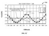
- FIG. 3Cis a graph 320 showing the effects of the application of the predetermined linear correction equation Cpre(x) with these coefficients.
- the off-track gain variationis reduced across the servo zones for the middle diameter, inner diameter, and outer diameter shown by lines 322 , 324 , and 330 , respectively.
- the outer diameter (OD) off-track gain variationis reduced to almost zero db utilizing the ⁇ 1 db compensation.
- these servo position correction coefficients (B 1 and B 2 ) for the pre-determined linear correction equation to apply the ⁇ 1 db off-track gain compensationmay be selected by a disk drive designer to allow for track following on the reserved track of the disk at the outer diameter (OD) with the pre-characterized off-track gain being almost completely accounted for.
- this processallows a disk drive designer to determine that the servo position correction coefficients (B 1 , B 2 ) imparting ⁇ 1 db gain, as shown in FIG. 3C are best for compensating for the off-track gain variation for the class of disk drives, such that there is almost no off-track gain variation during track following at the reserved track at the OD of the disk.
- the selected servo position correction coefficients (B 1 , B 2 ) for the class of disk driveswould then be coded into the firmware of the servo controller for each disk drive.
- the servo controllerthen implements the firmware during power-up to: calculate servo position correction values using the set of programmed servo position correction coefficients (B 1 and B 2 ) that have been pre-selected for the disk drive; store the servo position correction values in a pre-determined servo position correction look-up table in memory; and then utilize the pre-determined servo position correction look-up table to track follow on the reserved track of the disk at the outer diameter (OD) of the disk to perform initialization and calibration functions.
- a suitable pre-determined look-up table of I(x) values based upon Cpre(x)may be generated for a generalized servo zone and stored in memory.
- the linearly compensated ideal position (I(x))may be outputted from the look-up table for use in PES determination and track following on the reserved track at the OD, as will be more particularly described hereinafter.
- FIG. 4is a flow diagram illustrating a process 400 for determining whether a calibrated servo position correction table is in the reserved track.
- the servo controllerdetermines whether or not a calibrated servo position correction table is present in the reserved track (block 402 ). If there is not a calibrated servo position correction table in the reserved track, the servo controller continues to use the pre-determined servo position correction look-up table to track follow on the reserved track and other tracks to characterize the off-track gain variation for that disk drive and determine a calibrated set of servo position coefficients specific for the disk drive (block 404 ).
- This calibrationmay occur during the manufacture of the disk drive when the disk drive is connected to the test computer equipment and is being calibrated.
- the servo controllerdetermines a calibrated set of servo position coefficients based upon the linear correction function C(x) previously discussed, and shown below:
- C ( x )A 1 cos( wx )+ B 1 sin( wx )+ A 2 cos(2 wx )+ B 2 sin(2 wx )+ . . . + A 5 cos(5 wx )+ B 5 sin(5 wx )
- the servo controllermay calculate new calibrated servo position correction values (block 406 ) based upon the complete linear correction equation C(x) by calculating the off-track gain variation for a generalized servo zone using the pre-determined look-up table [based upon Cpre(x)] for track following and determines a complete set of appropriate coefficients A 1 -A 5 and B 1 -B 5 for the appropriate attenuation.
- the new B1 and B2 coefficientsmay be adjusted because the pre-determined B1 and B2 coefficients were used for track following when generating the new B1 and B2 coefficients.
- the new B1 coefficientmay be increased by the predetermined B1 coefficient and the new B2 coefficient may be increased by the predetermined B2 coefficient.
- the servo controllermay calculate new calibrated servo position correction values solely based on the linear correction equation Cpre(x).
- the calibrated servo position correction valuesare calculated (block 406 ) and the calibrated servo position correction values are stored in a calibrated servo position correction look-up table in the reserved track (block 408 ).
- the pre-determined servo position correction tableis then replaced with the calibrated servo position correction look-up table in memory.
- the calibrated servo position correction values from the calibrated servo position correction look-up tableare then utilized in track following (block 410 ).
- the calibrated servo position correction tableis already in the reserved track when the disk drive is powered-on and initializing (block 402 )
- the pre-determined servo position correction tableis simply replaced with the calibrated servo position correction table in memory (block 420 ).
- the calibrated servo position correction values from the calibrated servo position correction tableare then utilized in track following (block 422 ).
- FIG. 5is a flow diagram illustrating a process 500 by which the pre-determined servo position correction look-up table is utilized to track follow on the reserved track of the disk drive, according to one embodiment of the invention.
- servo burstsare read (block 502 )
- a servo zoneis determined (block 504 )
- an uncorrected servo position valueis determined (block 506 ).
- servo burst and servo zone definition as well as servo zone and servo position value determinationmay be accomplished in accordance with U.S. Pat. No. 6,995,941.
- the amplitudes of read servo burstse.g., A, B, C, D
- the amplitudes of read servo burstsare compared to first determine a radial servo position zone.
- eight servo zonesare defined spanning two track lengths. This can be seen with reference to FIG.
- An uncorrected servo position valuemay be calculated based upon the read servo bursts (e.g., A, B, C, D) and various burst ratios in accordance with position equations set forth in the '941 patent.
- the servo controllerutilizes the determined uncorrected servo position value y(x) as an index into the pre-determined servo correction look-up table (block 510 ), and finds a linear compensated servo position value (block 512 ) and this value is used to determine a position error signal (PES) for use in track following 515 .
- PESposition error signal
- the pre-determined servo correction look-up table(block 510 ) outputs the linearly compensated position (I(x)) (block 512 ) which is then used in PES determination and track following (block 515 ).
- the off-track gain variation for the class of disk drivescan be compensated for upon power-up and initialization such that the servo controller of the disk drive can properly track follow on the reserved track of the disk to accomplish initialization and calibration functions.
- the pre-determined servo position correction look-up table 510is replaced in memory with the calibrated servo burst correction table and the calibrated servo position correction values are utilized in track following, as previously described.
Landscapes
- Moving Of The Head To Find And Align With The Track (AREA)
Abstract
Description
C(x)=A1 cos(wx)+B1 sin(wx)+A2 cos(2wx)+B2 sin(2wx)+ . . . +A5 cos(5wx)+B5 sin(5wx)
Cpre(x)=B1 sin(wx)+B2 sin(2wx)
| gain | |||||
| 1 | 2 | 3 | 4 db | 5 db | |
| B1Def- | −2692.86 | −5046.90 | −7132.15 | −8999.35 | −10686.381 |
| PEComp | |||||
| B2Def- | −484.97 | −852.72 | −1133.09 | −1346.77 | −1508.61 |
| PEComp | |||||
C(x)=A1 cos(wx)+B1 sin(wx)+A2 cos(2wx)+B2 sin(2wx)+ . . . +A5 cos(5wx)+B5 sin(5wx)
Claims (23)
Priority Applications (1)
| Application Number | Priority Date | Filing Date | Title |
|---|---|---|---|
| US11/762,620US7492546B1 (en) | 2007-06-13 | 2007-06-13 | Providing pre-determined servo position correction values for use during disk drive initialization |
Applications Claiming Priority (1)
| Application Number | Priority Date | Filing Date | Title |
|---|---|---|---|
| US11/762,620US7492546B1 (en) | 2007-06-13 | 2007-06-13 | Providing pre-determined servo position correction values for use during disk drive initialization |
Publications (1)
| Publication Number | Publication Date |
|---|---|
| US7492546B1true US7492546B1 (en) | 2009-02-17 |
Family
ID=40349344
Family Applications (1)
| Application Number | Title | Priority Date | Filing Date |
|---|---|---|---|
| US11/762,620Expired - Fee RelatedUS7492546B1 (en) | 2007-06-13 | 2007-06-13 | Providing pre-determined servo position correction values for use during disk drive initialization |
Country Status (1)
| Country | Link |
|---|---|
| US (1) | US7492546B1 (en) |
Cited By (102)
| Publication number | Priority date | Publication date | Assignee | Title |
|---|---|---|---|---|
| US8824081B1 (en) | 2012-03-13 | 2014-09-02 | Western Digital Technologies, Inc. | Disk drive employing radially coherent reference pattern for servo burst demodulation and fly height measurement |
| US8830617B1 (en) | 2013-05-30 | 2014-09-09 | Western Digital Technologies, Inc. | Disk drive adjusting state estimator to compensate for unreliable servo data |
| US8879191B1 (en) | 2012-11-14 | 2014-11-04 | Western Digital Technologies, Inc. | Disk drive modifying rotational position optimization algorithm to achieve target performance for limited stroke |
| US8891191B1 (en) | 2014-05-06 | 2014-11-18 | Western Digital Technologies, Inc. | Data storage device initializing read signal gain to detect servo seed pattern |
| US8891194B1 (en) | 2013-05-14 | 2014-11-18 | Western Digital Technologies, Inc. | Disk drive iteratively adapting correction value that compensates for non-linearity of head |
| US8896957B1 (en) | 2013-05-10 | 2014-11-25 | Western Digital Technologies, Inc. | Disk drive performing spiral scan of disk surface to detect residual data |
| US8902539B1 (en) | 2014-05-13 | 2014-12-02 | Western Digital Technologies, Inc. | Data storage device reducing seek power consumption |
| US8902538B1 (en) | 2013-03-29 | 2014-12-02 | Western Digital Technologies, Inc. | Disk drive detecting crack in microactuator |
| US8913342B1 (en) | 2014-03-21 | 2014-12-16 | Western Digital Technologies, Inc. | Data storage device adjusting range of microactuator digital-to-analog converter based on operating temperature |
| US8917475B1 (en) | 2013-12-20 | 2014-12-23 | Western Digital Technologies, Inc. | Disk drive generating a disk locked clock using radial dependent timing feed-forward compensation |
| US8917474B1 (en) | 2011-08-08 | 2014-12-23 | Western Digital Technologies, Inc. | Disk drive calibrating a velocity profile prior to writing a spiral track |
| US8922940B1 (en) | 2014-05-27 | 2014-12-30 | Western Digital Technologies, Inc. | Data storage device reducing spindle motor voltage boost during power failure |
| US8922938B1 (en) | 2012-11-02 | 2014-12-30 | Western Digital Technologies, Inc. | Disk drive filtering disturbance signal and error signal for adaptive feed-forward compensation |
| US8922937B1 (en) | 2012-04-19 | 2014-12-30 | Western Digital Technologies, Inc. | Disk drive evaluating multiple vibration sensor outputs to enable write-protection |
| US8922931B1 (en) | 2013-05-13 | 2014-12-30 | Western Digital Technologies, Inc. | Disk drive releasing variable amount of buffered write data based on sliding window of predicted servo quality |
| US8929021B1 (en) | 2012-03-27 | 2015-01-06 | Western Digital Technologies, Inc. | Disk drive servo writing from spiral tracks using radial dependent timing feed-forward compensation |
| US8929022B1 (en) | 2012-12-19 | 2015-01-06 | Western Digital Technologies, Inc. | Disk drive detecting microactuator degradation by evaluating frequency component of servo signal |
| US8934186B1 (en) | 2014-03-26 | 2015-01-13 | Western Digital Technologies, Inc. | Data storage device estimating servo zone to reduce size of track address |
| US8937784B1 (en) | 2012-08-01 | 2015-01-20 | Western Digital Technologies, Inc. | Disk drive employing feed-forward compensation and phase shift compensation during seek settling |
| US8941945B1 (en) | 2014-06-06 | 2015-01-27 | Western Digital Technologies, Inc. | Data storage device servoing heads based on virtual servo tracks |
| US8941939B1 (en) | 2013-10-24 | 2015-01-27 | Western Digital Technologies, Inc. | Disk drive using VCM BEMF feed-forward compensation to write servo data to a disk |
| US8947819B1 (en) | 2012-08-28 | 2015-02-03 | Western Digital Technologies, Inc. | Disk drive implementing hysteresis for primary shock detector based on a more sensitive secondary shock detector |
| US8953278B1 (en) | 2011-11-16 | 2015-02-10 | Western Digital Technologies, Inc. | Disk drive selecting disturbance signal for feed-forward compensation |
| US8953271B1 (en) | 2013-05-13 | 2015-02-10 | Western Digital Technologies, Inc. | Disk drive compensating for repeatable run out selectively per zone |
| US8958169B1 (en) | 2014-06-11 | 2015-02-17 | Western Digital Technologies, Inc. | Data storage device re-qualifying state estimator while decelerating head |
| US8970979B1 (en) | 2013-12-18 | 2015-03-03 | Western Digital Technologies, Inc. | Disk drive determining frequency response of actuator near servo sample frequency |
| US8982490B1 (en) | 2014-04-24 | 2015-03-17 | Western Digital Technologies, Inc. | Data storage device reading first spiral track while simultaneously writing second spiral track |
| US8982501B1 (en) | 2014-09-22 | 2015-03-17 | Western Digital Technologies, Inc. | Data storage device compensating for repeatable disturbance when commutating a spindle motor |
| US8995075B1 (en) | 2012-06-21 | 2015-03-31 | Western Digital Technologies, Inc. | Disk drive adjusting estimated servo state to compensate for transient when crossing a servo zone boundary |
| US8995082B1 (en) | 2011-06-03 | 2015-03-31 | Western Digital Technologies, Inc. | Reducing acoustic noise in a disk drive when exiting idle mode |
| US9001454B1 (en) | 2013-04-12 | 2015-04-07 | Western Digital Technologies, Inc. | Disk drive adjusting phase of adaptive feed-forward controller when reconfiguring servo loop |
| US9007714B1 (en) | 2014-07-18 | 2015-04-14 | Western Digital Technologies Inc. | Data storage device comprising slew rate anti-windup compensation for microactuator |
| US9013824B1 (en) | 2014-06-04 | 2015-04-21 | Western Digital Technologies, Inc. | Data storage device comprising dual read sensors and dual servo channels to improve servo demodulation |
| US9013825B1 (en) | 2014-03-24 | 2015-04-21 | Western Digital Technologies, Inc. | Electronic system with vibration management mechanism and method of operation thereof |
| US9025269B1 (en) | 2014-01-02 | 2015-05-05 | Western Digital Technologies, Inc. | Disk drive compensating for cycle slip of disk locked clock when reading mini-wedge |
| US9026728B1 (en) | 2013-06-06 | 2015-05-05 | Western Digital Technologies, Inc. | Disk drive applying feed-forward compensation when writing consecutive data tracks |
| US9047901B1 (en) | 2013-05-28 | 2015-06-02 | Western Digital Technologies, Inc. | Disk drive measuring spiral track error by measuring a slope of a spiral track across a disk radius |
| US9047932B1 (en) | 2014-03-21 | 2015-06-02 | Western Digital Technologies, Inc. | Data storage device adjusting a power loss threshold based on samples of supply voltage |
| US9047919B1 (en) | 2013-03-12 | 2015-06-02 | Western Digitial Technologies, Inc. | Disk drive initializing servo read channel by reading data preceding servo preamble during access operation |
| US9053727B1 (en) | 2014-06-02 | 2015-06-09 | Western Digital Technologies, Inc. | Disk drive opening spiral crossing window based on DC and AC spiral track error |
| US9053726B1 (en) | 2014-01-29 | 2015-06-09 | Western Digital Technologies, Inc. | Data storage device on-line adapting disturbance observer filter |
| US9053712B1 (en) | 2014-05-07 | 2015-06-09 | Western Digital Technologies, Inc. | Data storage device reading servo sector while writing data sector |
| US9058834B1 (en) | 2013-11-08 | 2015-06-16 | Western Digital Technologies, Inc. | Power architecture for low power modes in storage devices |
| US9058827B1 (en) | 2013-06-25 | 2015-06-16 | Western Digitial Technologies, Inc. | Disk drive optimizing filters based on sensor signal and disturbance signal for adaptive feed-forward compensation |
| US9058826B1 (en) | 2014-02-13 | 2015-06-16 | Western Digital Technologies, Inc. | Data storage device detecting free fall condition from disk speed variations |
| US9064537B1 (en) | 2013-09-13 | 2015-06-23 | Western Digital Technologies, Inc. | Disk drive measuring radial offset between heads by detecting a difference between ramp contact |
| US9076473B1 (en) | 2014-08-12 | 2015-07-07 | Western Digital Technologies, Inc. | Data storage device detecting fly height instability of head during load operation based on microactuator response |
| US9076471B1 (en) | 2013-07-31 | 2015-07-07 | Western Digital Technologies, Inc. | Fall detection scheme using FFS |
| US9076490B1 (en) | 2012-12-12 | 2015-07-07 | Western Digital Technologies, Inc. | Disk drive writing radial offset spiral servo tracks by reading spiral seed tracks |
| US9076472B1 (en) | 2014-08-21 | 2015-07-07 | Western Digital (Fremont), Llc | Apparatus enabling writing servo data when disk reaches target rotation speed |
| US9093105B2 (en) | 2011-12-09 | 2015-07-28 | Western Digital Technologies, Inc. | Disk drive charging capacitor using motor supply voltage during power failure |
| US9099147B1 (en) | 2014-09-22 | 2015-08-04 | Western Digital Technologies, Inc. | Data storage device commutating a spindle motor using closed-loop rotation phase alignment |
| US9111575B1 (en) | 2014-10-23 | 2015-08-18 | Western Digital Technologies, Inc. | Data storage device employing adaptive feed-forward control in timing loop to compensate for vibration |
| US9129630B1 (en) | 2014-12-16 | 2015-09-08 | Western Digital Technologies, Inc. | Data storage device employing full servo sectors on first disk surface and mini servo sectors on second disk surface |
| US9142235B1 (en) | 2009-10-27 | 2015-09-22 | Western Digital Technologies, Inc. | Disk drive characterizing microactuator by injecting sinusoidal disturbance and evaluating feed-forward compensation values |
| US9141177B1 (en) | 2014-03-21 | 2015-09-22 | Western Digital Technologies, Inc. | Data storage device employing glitch compensation for power loss detection |
| US9142249B1 (en) | 2013-12-06 | 2015-09-22 | Western Digital Technologies, Inc. | Disk drive using timing loop control signal for vibration compensation in servo loop |
| US9142225B1 (en) | 2014-03-21 | 2015-09-22 | Western Digital Technologies, Inc. | Electronic system with actuator control mechanism and method of operation thereof |
| US9147428B1 (en) | 2013-04-24 | 2015-09-29 | Western Digital Technologies, Inc. | Disk drive with improved spin-up control |
| US9147418B1 (en) | 2013-06-20 | 2015-09-29 | Western Digital Technologies, Inc. | Disk drive compensating for microactuator gain variations |
| US9153283B1 (en) | 2014-09-30 | 2015-10-06 | Western Digital Technologies, Inc. | Data storage device compensating for hysteretic response of microactuator |
| US9165583B1 (en) | 2014-10-29 | 2015-10-20 | Western Digital Technologies, Inc. | Data storage device adjusting seek profile based on seek length when ending track is near ramp |
| US9171567B1 (en) | 2014-05-27 | 2015-10-27 | Western Digital Technologies, Inc. | Data storage device employing sliding mode control of spindle motor |
| US9171568B1 (en) | 2014-06-25 | 2015-10-27 | Western Digital Technologies, Inc. | Data storage device periodically re-initializing spindle motor commutation sequence based on timing data |
| US9208808B1 (en) | 2014-04-22 | 2015-12-08 | Western Digital Technologies, Inc. | Electronic system with unload management mechanism and method of operation thereof |
| US9208810B1 (en) | 2014-04-24 | 2015-12-08 | Western Digital Technologies, Inc. | Data storage device attenuating interference from first spiral track when reading second spiral track |
| US9208815B1 (en) | 2014-10-09 | 2015-12-08 | Western Digital Technologies, Inc. | Data storage device dynamically reducing coast velocity during seek to reduce power consumption |
| US9214175B1 (en) | 2015-03-16 | 2015-12-15 | Western Digital Technologies, Inc. | Data storage device configuring a gain of a servo control system for actuating a head over a disk |
| US9230593B1 (en) | 2014-12-23 | 2016-01-05 | Western Digital Technologies, Inc. | Data storage device optimizing spindle motor power when transitioning into a power failure mode |
| US9230592B1 (en) | 2014-12-23 | 2016-01-05 | Western Digital Technologies, Inc. | Electronic system with a method of motor spindle bandwidth estimation and calibration thereof |
| US9245577B1 (en) | 2015-03-26 | 2016-01-26 | Western Digital Technologies, Inc. | Data storage device comprising spindle motor current sensing with supply voltage noise attenuation |
| US9245540B1 (en) | 2014-10-29 | 2016-01-26 | Western Digital Technologies, Inc. | Voice coil motor temperature sensing circuit to reduce catastrophic failure due to voice coil motor coil shorting to ground |
| US9245560B1 (en) | 2015-03-09 | 2016-01-26 | Western Digital Technologies, Inc. | Data storage device measuring reader/writer offset by reading spiral track and concentric servo sectors |
| US9251823B1 (en) | 2014-12-10 | 2016-02-02 | Western Digital Technologies, Inc. | Data storage device delaying seek operation to avoid thermal asperities |
| US9269386B1 (en) | 2014-01-29 | 2016-02-23 | Western Digital Technologies, Inc. | Data storage device on-line adapting disturbance observer filter |
| US9286925B1 (en) | 2015-03-26 | 2016-03-15 | Western Digital Technologies, Inc. | Data storage device writing multiple burst correction values at the same radial location |
| US9286927B1 (en) | 2014-12-16 | 2016-03-15 | Western Digital Technologies, Inc. | Data storage device demodulating servo burst by computing slope of intermediate integration points |
| US9343102B1 (en) | 2015-03-25 | 2016-05-17 | Western Digital Technologies, Inc. | Data storage device employing a phase offset to generate power from a spindle motor during a power failure |
| US9343094B1 (en) | 2015-03-26 | 2016-05-17 | Western Digital Technologies, Inc. | Data storage device filtering burst correction values before downsampling the burst correction values |
| US9350278B1 (en) | 2014-06-13 | 2016-05-24 | Western Digital Technologies, Inc. | Circuit technique to integrate voice coil motor support elements |
| US9349401B1 (en) | 2014-07-24 | 2016-05-24 | Western Digital Technologies, Inc. | Electronic system with media scan mechanism and method of operation thereof |
| US9355676B1 (en) | 2015-03-25 | 2016-05-31 | Western Digital Technologies, Inc. | Data storage device controlling amplitude and phase of driving voltage to generate power from a spindle motor |
| US9355667B1 (en) | 2014-11-11 | 2016-05-31 | Western Digital Technologies, Inc. | Data storage device saving absolute position at each servo wedge for previous write operations |
| US9361939B1 (en) | 2014-03-10 | 2016-06-07 | Western Digital Technologies, Inc. | Data storage device characterizing geometry of magnetic transitions |
| US9396751B1 (en) | 2015-06-26 | 2016-07-19 | Western Digital Technologies, Inc. | Data storage device compensating for fabrication tolerances when measuring spindle motor current |
| US9407015B1 (en) | 2014-12-29 | 2016-08-02 | Western Digital Technologies, Inc. | Automatic power disconnect device |
| US9418689B2 (en) | 2014-10-09 | 2016-08-16 | Western Digital Technologies, Inc. | Data storage device generating an operating seek time profile as a function of a base seek time profile |
| US9424868B1 (en) | 2015-05-12 | 2016-08-23 | Western Digital Technologies, Inc. | Data storage device employing spindle motor driving profile during seek to improve power performance |
| US9424871B1 (en) | 2012-09-13 | 2016-08-23 | Western Digital Technologies, Inc. | Disk drive correcting an error in a detected gray code |
| US9437237B1 (en) | 2015-02-20 | 2016-09-06 | Western Digital Technologies, Inc. | Method to detect power loss through data storage device spindle speed |
| US9437231B1 (en) | 2015-09-25 | 2016-09-06 | Western Digital Technologies, Inc. | Data storage device concurrently controlling and sensing a secondary actuator for actuating a head over a disk |
| US9454212B1 (en) | 2014-12-08 | 2016-09-27 | Western Digital Technologies, Inc. | Wakeup detector |
| US9471072B1 (en) | 2013-11-14 | 2016-10-18 | Western Digital Technologies, Inc | Self-adaptive voltage scaling |
| US9484733B1 (en) | 2013-09-11 | 2016-11-01 | Western Digital Technologies, Inc. | Power control module for data storage device |
| US9542966B1 (en) | 2015-07-09 | 2017-01-10 | Western Digital Technologies, Inc. | Data storage devices and methods with frequency-shaped sliding mode control |
| US9564162B1 (en) | 2015-12-28 | 2017-02-07 | Western Digital Technologies, Inc. | Data storage device measuring resonant frequency of a shock sensor by applying differential excitation and measuring oscillation |
| US9581978B1 (en) | 2014-12-17 | 2017-02-28 | Western Digital Technologies, Inc. | Electronic system with servo management mechanism and method of operation thereof |
| US9620160B1 (en) | 2015-12-28 | 2017-04-11 | Western Digital Technologies, Inc. | Data storage device measuring resonant frequency of a shock sensor by inserting the shock sensor into an oscillator circuit |
| US9823294B1 (en) | 2013-10-29 | 2017-11-21 | Western Digital Technologies, Inc. | Negative voltage testing methodology and tester |
| US9886285B2 (en) | 2015-03-31 | 2018-02-06 | Western Digital Technologies, Inc. | Communication interface initialization |
| US9899834B1 (en) | 2015-11-18 | 2018-02-20 | Western Digital Technologies, Inc. | Power control module using protection circuit for regulating backup voltage to power load during power fault |
| US9959204B1 (en) | 2015-03-09 | 2018-05-01 | Western Digital Technologies, Inc. | Tracking sequential ranges of non-ordered data |
Citations (8)
| Publication number | Priority date | Publication date | Assignee | Title |
|---|---|---|---|---|
| US5339206A (en)* | 1992-03-31 | 1994-08-16 | Fujitsu Limited | Positioning control method and apparatus of head which is used in magnetic disk apparatus |
| US6421198B1 (en) | 1999-04-27 | 2002-07-16 | International Business Machines Corporation | Linearity compensation for a position error signal based on repeatable and non-repeatable run out in a disk drive |
| US6798606B2 (en) | 2002-01-22 | 2004-09-28 | International Business Machines Corporation | Position error signal linearization calibration |
| US6937424B2 (en) | 2003-05-12 | 2005-08-30 | Hitachi Global Storage Technologies Netherlands N.V. | Repeatable runout (RRO) compensation methods and apparatus for data storage devices |
| US6995941B1 (en) | 2005-01-07 | 2006-02-07 | Western Digital Technologies, Inc. | Method for improving head position determination in a disk drive |
| US7139150B2 (en) | 2004-02-10 | 2006-11-21 | Marvell International Ltd. | Method and system for head position control in embedded disk drive controllers |
| US7286316B2 (en)* | 2005-05-20 | 2007-10-23 | Hitachi Global Storage Technologies Netherlands B.V. | Method and data storage device for writing patterns onto recording disk |
| US7391584B1 (en)* | 2006-11-07 | 2008-06-24 | Western Digital Technologies, Inc. | Compensating for repeatable phase error when servo writing a disk drive from spiral tracks |
- 2007
- 2007-06-13USUS11/762,620patent/US7492546B1/ennot_activeExpired - Fee Related
Patent Citations (8)
| Publication number | Priority date | Publication date | Assignee | Title |
|---|---|---|---|---|
| US5339206A (en)* | 1992-03-31 | 1994-08-16 | Fujitsu Limited | Positioning control method and apparatus of head which is used in magnetic disk apparatus |
| US6421198B1 (en) | 1999-04-27 | 2002-07-16 | International Business Machines Corporation | Linearity compensation for a position error signal based on repeatable and non-repeatable run out in a disk drive |
| US6798606B2 (en) | 2002-01-22 | 2004-09-28 | International Business Machines Corporation | Position error signal linearization calibration |
| US6937424B2 (en) | 2003-05-12 | 2005-08-30 | Hitachi Global Storage Technologies Netherlands N.V. | Repeatable runout (RRO) compensation methods and apparatus for data storage devices |
| US7139150B2 (en) | 2004-02-10 | 2006-11-21 | Marvell International Ltd. | Method and system for head position control in embedded disk drive controllers |
| US6995941B1 (en) | 2005-01-07 | 2006-02-07 | Western Digital Technologies, Inc. | Method for improving head position determination in a disk drive |
| US7286316B2 (en)* | 2005-05-20 | 2007-10-23 | Hitachi Global Storage Technologies Netherlands B.V. | Method and data storage device for writing patterns onto recording disk |
| US7391584B1 (en)* | 2006-11-07 | 2008-06-24 | Western Digital Technologies, Inc. | Compensating for repeatable phase error when servo writing a disk drive from spiral tracks |
Cited By (107)
| Publication number | Priority date | Publication date | Assignee | Title |
|---|---|---|---|---|
| US9142235B1 (en) | 2009-10-27 | 2015-09-22 | Western Digital Technologies, Inc. | Disk drive characterizing microactuator by injecting sinusoidal disturbance and evaluating feed-forward compensation values |
| US8995082B1 (en) | 2011-06-03 | 2015-03-31 | Western Digital Technologies, Inc. | Reducing acoustic noise in a disk drive when exiting idle mode |
| US8917474B1 (en) | 2011-08-08 | 2014-12-23 | Western Digital Technologies, Inc. | Disk drive calibrating a velocity profile prior to writing a spiral track |
| US8953278B1 (en) | 2011-11-16 | 2015-02-10 | Western Digital Technologies, Inc. | Disk drive selecting disturbance signal for feed-forward compensation |
| US9093105B2 (en) | 2011-12-09 | 2015-07-28 | Western Digital Technologies, Inc. | Disk drive charging capacitor using motor supply voltage during power failure |
| US9390749B2 (en) | 2011-12-09 | 2016-07-12 | Western Digital Technologies, Inc. | Power failure management in disk drives |
| US8824081B1 (en) | 2012-03-13 | 2014-09-02 | Western Digital Technologies, Inc. | Disk drive employing radially coherent reference pattern for servo burst demodulation and fly height measurement |
| US8929021B1 (en) | 2012-03-27 | 2015-01-06 | Western Digital Technologies, Inc. | Disk drive servo writing from spiral tracks using radial dependent timing feed-forward compensation |
| US8934191B1 (en) | 2012-03-27 | 2015-01-13 | Western Digital Technologies, Inc. | Disk drive generating a disk locked clock using radial dependent timing feed-forward compensation |
| US8922937B1 (en) | 2012-04-19 | 2014-12-30 | Western Digital Technologies, Inc. | Disk drive evaluating multiple vibration sensor outputs to enable write-protection |
| US9454989B1 (en) | 2012-06-21 | 2016-09-27 | Western Digital Technologies, Inc. | Disk drive adjusting estimated servo state to compensate for transient when crossing a servo zone boundary |
| US8995075B1 (en) | 2012-06-21 | 2015-03-31 | Western Digital Technologies, Inc. | Disk drive adjusting estimated servo state to compensate for transient when crossing a servo zone boundary |
| US8937784B1 (en) | 2012-08-01 | 2015-01-20 | Western Digital Technologies, Inc. | Disk drive employing feed-forward compensation and phase shift compensation during seek settling |
| US8947819B1 (en) | 2012-08-28 | 2015-02-03 | Western Digital Technologies, Inc. | Disk drive implementing hysteresis for primary shock detector based on a more sensitive secondary shock detector |
| US9424871B1 (en) | 2012-09-13 | 2016-08-23 | Western Digital Technologies, Inc. | Disk drive correcting an error in a detected gray code |
| US8922938B1 (en) | 2012-11-02 | 2014-12-30 | Western Digital Technologies, Inc. | Disk drive filtering disturbance signal and error signal for adaptive feed-forward compensation |
| US8879191B1 (en) | 2012-11-14 | 2014-11-04 | Western Digital Technologies, Inc. | Disk drive modifying rotational position optimization algorithm to achieve target performance for limited stroke |
| US9076490B1 (en) | 2012-12-12 | 2015-07-07 | Western Digital Technologies, Inc. | Disk drive writing radial offset spiral servo tracks by reading spiral seed tracks |
| US8929022B1 (en) | 2012-12-19 | 2015-01-06 | Western Digital Technologies, Inc. | Disk drive detecting microactuator degradation by evaluating frequency component of servo signal |
| US9047919B1 (en) | 2013-03-12 | 2015-06-02 | Western Digitial Technologies, Inc. | Disk drive initializing servo read channel by reading data preceding servo preamble during access operation |
| US8902538B1 (en) | 2013-03-29 | 2014-12-02 | Western Digital Technologies, Inc. | Disk drive detecting crack in microactuator |
| US9001454B1 (en) | 2013-04-12 | 2015-04-07 | Western Digital Technologies, Inc. | Disk drive adjusting phase of adaptive feed-forward controller when reconfiguring servo loop |
| US9147428B1 (en) | 2013-04-24 | 2015-09-29 | Western Digital Technologies, Inc. | Disk drive with improved spin-up control |
| US8896957B1 (en) | 2013-05-10 | 2014-11-25 | Western Digital Technologies, Inc. | Disk drive performing spiral scan of disk surface to detect residual data |
| US8922931B1 (en) | 2013-05-13 | 2014-12-30 | Western Digital Technologies, Inc. | Disk drive releasing variable amount of buffered write data based on sliding window of predicted servo quality |
| US8953271B1 (en) | 2013-05-13 | 2015-02-10 | Western Digital Technologies, Inc. | Disk drive compensating for repeatable run out selectively per zone |
| US8891194B1 (en) | 2013-05-14 | 2014-11-18 | Western Digital Technologies, Inc. | Disk drive iteratively adapting correction value that compensates for non-linearity of head |
| US9047901B1 (en) | 2013-05-28 | 2015-06-02 | Western Digital Technologies, Inc. | Disk drive measuring spiral track error by measuring a slope of a spiral track across a disk radius |
| US8830617B1 (en) | 2013-05-30 | 2014-09-09 | Western Digital Technologies, Inc. | Disk drive adjusting state estimator to compensate for unreliable servo data |
| US9026728B1 (en) | 2013-06-06 | 2015-05-05 | Western Digital Technologies, Inc. | Disk drive applying feed-forward compensation when writing consecutive data tracks |
| US9147418B1 (en) | 2013-06-20 | 2015-09-29 | Western Digital Technologies, Inc. | Disk drive compensating for microactuator gain variations |
| US9058827B1 (en) | 2013-06-25 | 2015-06-16 | Western Digitial Technologies, Inc. | Disk drive optimizing filters based on sensor signal and disturbance signal for adaptive feed-forward compensation |
| US9076471B1 (en) | 2013-07-31 | 2015-07-07 | Western Digital Technologies, Inc. | Fall detection scheme using FFS |
| US9484733B1 (en) | 2013-09-11 | 2016-11-01 | Western Digital Technologies, Inc. | Power control module for data storage device |
| US9064537B1 (en) | 2013-09-13 | 2015-06-23 | Western Digital Technologies, Inc. | Disk drive measuring radial offset between heads by detecting a difference between ramp contact |
| US8941939B1 (en) | 2013-10-24 | 2015-01-27 | Western Digital Technologies, Inc. | Disk drive using VCM BEMF feed-forward compensation to write servo data to a disk |
| US9823294B1 (en) | 2013-10-29 | 2017-11-21 | Western Digital Technologies, Inc. | Negative voltage testing methodology and tester |
| US9058834B1 (en) | 2013-11-08 | 2015-06-16 | Western Digital Technologies, Inc. | Power architecture for low power modes in storage devices |
| US9471072B1 (en) | 2013-11-14 | 2016-10-18 | Western Digital Technologies, Inc | Self-adaptive voltage scaling |
| US9142249B1 (en) | 2013-12-06 | 2015-09-22 | Western Digital Technologies, Inc. | Disk drive using timing loop control signal for vibration compensation in servo loop |
| US8970979B1 (en) | 2013-12-18 | 2015-03-03 | Western Digital Technologies, Inc. | Disk drive determining frequency response of actuator near servo sample frequency |
| US8917475B1 (en) | 2013-12-20 | 2014-12-23 | Western Digital Technologies, Inc. | Disk drive generating a disk locked clock using radial dependent timing feed-forward compensation |
| US9025269B1 (en) | 2014-01-02 | 2015-05-05 | Western Digital Technologies, Inc. | Disk drive compensating for cycle slip of disk locked clock when reading mini-wedge |
| US9053726B1 (en) | 2014-01-29 | 2015-06-09 | Western Digital Technologies, Inc. | Data storage device on-line adapting disturbance observer filter |
| US9269386B1 (en) | 2014-01-29 | 2016-02-23 | Western Digital Technologies, Inc. | Data storage device on-line adapting disturbance observer filter |
| US9058826B1 (en) | 2014-02-13 | 2015-06-16 | Western Digital Technologies, Inc. | Data storage device detecting free fall condition from disk speed variations |
| US9361939B1 (en) | 2014-03-10 | 2016-06-07 | Western Digital Technologies, Inc. | Data storage device characterizing geometry of magnetic transitions |
| US8913342B1 (en) | 2014-03-21 | 2014-12-16 | Western Digital Technologies, Inc. | Data storage device adjusting range of microactuator digital-to-analog converter based on operating temperature |
| US9047932B1 (en) | 2014-03-21 | 2015-06-02 | Western Digital Technologies, Inc. | Data storage device adjusting a power loss threshold based on samples of supply voltage |
| US9141177B1 (en) | 2014-03-21 | 2015-09-22 | Western Digital Technologies, Inc. | Data storage device employing glitch compensation for power loss detection |
| US9142225B1 (en) | 2014-03-21 | 2015-09-22 | Western Digital Technologies, Inc. | Electronic system with actuator control mechanism and method of operation thereof |
| US9013825B1 (en) | 2014-03-24 | 2015-04-21 | Western Digital Technologies, Inc. | Electronic system with vibration management mechanism and method of operation thereof |
| US8934186B1 (en) | 2014-03-26 | 2015-01-13 | Western Digital Technologies, Inc. | Data storage device estimating servo zone to reduce size of track address |
| US9208808B1 (en) | 2014-04-22 | 2015-12-08 | Western Digital Technologies, Inc. | Electronic system with unload management mechanism and method of operation thereof |
| US9208810B1 (en) | 2014-04-24 | 2015-12-08 | Western Digital Technologies, Inc. | Data storage device attenuating interference from first spiral track when reading second spiral track |
| US8982490B1 (en) | 2014-04-24 | 2015-03-17 | Western Digital Technologies, Inc. | Data storage device reading first spiral track while simultaneously writing second spiral track |
| US8891191B1 (en) | 2014-05-06 | 2014-11-18 | Western Digital Technologies, Inc. | Data storage device initializing read signal gain to detect servo seed pattern |
| US9053712B1 (en) | 2014-05-07 | 2015-06-09 | Western Digital Technologies, Inc. | Data storage device reading servo sector while writing data sector |
| US8902539B1 (en) | 2014-05-13 | 2014-12-02 | Western Digital Technologies, Inc. | Data storage device reducing seek power consumption |
| US8922940B1 (en) | 2014-05-27 | 2014-12-30 | Western Digital Technologies, Inc. | Data storage device reducing spindle motor voltage boost during power failure |
| US9171567B1 (en) | 2014-05-27 | 2015-10-27 | Western Digital Technologies, Inc. | Data storage device employing sliding mode control of spindle motor |
| US9053727B1 (en) | 2014-06-02 | 2015-06-09 | Western Digital Technologies, Inc. | Disk drive opening spiral crossing window based on DC and AC spiral track error |
| US9013824B1 (en) | 2014-06-04 | 2015-04-21 | Western Digital Technologies, Inc. | Data storage device comprising dual read sensors and dual servo channels to improve servo demodulation |
| US8941945B1 (en) | 2014-06-06 | 2015-01-27 | Western Digital Technologies, Inc. | Data storage device servoing heads based on virtual servo tracks |
| US8958169B1 (en) | 2014-06-11 | 2015-02-17 | Western Digital Technologies, Inc. | Data storage device re-qualifying state estimator while decelerating head |
| US9350278B1 (en) | 2014-06-13 | 2016-05-24 | Western Digital Technologies, Inc. | Circuit technique to integrate voice coil motor support elements |
| US9171568B1 (en) | 2014-06-25 | 2015-10-27 | Western Digital Technologies, Inc. | Data storage device periodically re-initializing spindle motor commutation sequence based on timing data |
| US9007714B1 (en) | 2014-07-18 | 2015-04-14 | Western Digital Technologies Inc. | Data storage device comprising slew rate anti-windup compensation for microactuator |
| US9349401B1 (en) | 2014-07-24 | 2016-05-24 | Western Digital Technologies, Inc. | Electronic system with media scan mechanism and method of operation thereof |
| US9076473B1 (en) | 2014-08-12 | 2015-07-07 | Western Digital Technologies, Inc. | Data storage device detecting fly height instability of head during load operation based on microactuator response |
| US9076472B1 (en) | 2014-08-21 | 2015-07-07 | Western Digital (Fremont), Llc | Apparatus enabling writing servo data when disk reaches target rotation speed |
| US9099147B1 (en) | 2014-09-22 | 2015-08-04 | Western Digital Technologies, Inc. | Data storage device commutating a spindle motor using closed-loop rotation phase alignment |
| US8982501B1 (en) | 2014-09-22 | 2015-03-17 | Western Digital Technologies, Inc. | Data storage device compensating for repeatable disturbance when commutating a spindle motor |
| US9153283B1 (en) | 2014-09-30 | 2015-10-06 | Western Digital Technologies, Inc. | Data storage device compensating for hysteretic response of microactuator |
| US9208815B1 (en) | 2014-10-09 | 2015-12-08 | Western Digital Technologies, Inc. | Data storage device dynamically reducing coast velocity during seek to reduce power consumption |
| US9418689B2 (en) | 2014-10-09 | 2016-08-16 | Western Digital Technologies, Inc. | Data storage device generating an operating seek time profile as a function of a base seek time profile |
| US9111575B1 (en) | 2014-10-23 | 2015-08-18 | Western Digital Technologies, Inc. | Data storage device employing adaptive feed-forward control in timing loop to compensate for vibration |
| US9245540B1 (en) | 2014-10-29 | 2016-01-26 | Western Digital Technologies, Inc. | Voice coil motor temperature sensing circuit to reduce catastrophic failure due to voice coil motor coil shorting to ground |
| US9165583B1 (en) | 2014-10-29 | 2015-10-20 | Western Digital Technologies, Inc. | Data storage device adjusting seek profile based on seek length when ending track is near ramp |
| US9355667B1 (en) | 2014-11-11 | 2016-05-31 | Western Digital Technologies, Inc. | Data storage device saving absolute position at each servo wedge for previous write operations |
| US9454212B1 (en) | 2014-12-08 | 2016-09-27 | Western Digital Technologies, Inc. | Wakeup detector |
| US9251823B1 (en) | 2014-12-10 | 2016-02-02 | Western Digital Technologies, Inc. | Data storage device delaying seek operation to avoid thermal asperities |
| US9286927B1 (en) | 2014-12-16 | 2016-03-15 | Western Digital Technologies, Inc. | Data storage device demodulating servo burst by computing slope of intermediate integration points |
| US9129630B1 (en) | 2014-12-16 | 2015-09-08 | Western Digital Technologies, Inc. | Data storage device employing full servo sectors on first disk surface and mini servo sectors on second disk surface |
| US9581978B1 (en) | 2014-12-17 | 2017-02-28 | Western Digital Technologies, Inc. | Electronic system with servo management mechanism and method of operation thereof |
| US9230592B1 (en) | 2014-12-23 | 2016-01-05 | Western Digital Technologies, Inc. | Electronic system with a method of motor spindle bandwidth estimation and calibration thereof |
| US9230593B1 (en) | 2014-12-23 | 2016-01-05 | Western Digital Technologies, Inc. | Data storage device optimizing spindle motor power when transitioning into a power failure mode |
| US9761266B2 (en) | 2014-12-23 | 2017-09-12 | Western Digital Technologies, Inc. | Data storage device optimizing spindle motor power when transitioning into a power failure mode |
| US9407015B1 (en) | 2014-12-29 | 2016-08-02 | Western Digital Technologies, Inc. | Automatic power disconnect device |
| US9437237B1 (en) | 2015-02-20 | 2016-09-06 | Western Digital Technologies, Inc. | Method to detect power loss through data storage device spindle speed |
| US9245560B1 (en) | 2015-03-09 | 2016-01-26 | Western Digital Technologies, Inc. | Data storage device measuring reader/writer offset by reading spiral track and concentric servo sectors |
| US9959204B1 (en) | 2015-03-09 | 2018-05-01 | Western Digital Technologies, Inc. | Tracking sequential ranges of non-ordered data |
| US9214175B1 (en) | 2015-03-16 | 2015-12-15 | Western Digital Technologies, Inc. | Data storage device configuring a gain of a servo control system for actuating a head over a disk |
| US9355676B1 (en) | 2015-03-25 | 2016-05-31 | Western Digital Technologies, Inc. | Data storage device controlling amplitude and phase of driving voltage to generate power from a spindle motor |
| US9343102B1 (en) | 2015-03-25 | 2016-05-17 | Western Digital Technologies, Inc. | Data storage device employing a phase offset to generate power from a spindle motor during a power failure |
| US9343094B1 (en) | 2015-03-26 | 2016-05-17 | Western Digital Technologies, Inc. | Data storage device filtering burst correction values before downsampling the burst correction values |
| US9286925B1 (en) | 2015-03-26 | 2016-03-15 | Western Digital Technologies, Inc. | Data storage device writing multiple burst correction values at the same radial location |
| US9245577B1 (en) | 2015-03-26 | 2016-01-26 | Western Digital Technologies, Inc. | Data storage device comprising spindle motor current sensing with supply voltage noise attenuation |
| US9886285B2 (en) | 2015-03-31 | 2018-02-06 | Western Digital Technologies, Inc. | Communication interface initialization |
| US9424868B1 (en) | 2015-05-12 | 2016-08-23 | Western Digital Technologies, Inc. | Data storage device employing spindle motor driving profile during seek to improve power performance |
| US9396751B1 (en) | 2015-06-26 | 2016-07-19 | Western Digital Technologies, Inc. | Data storage device compensating for fabrication tolerances when measuring spindle motor current |
| US9542966B1 (en) | 2015-07-09 | 2017-01-10 | Western Digital Technologies, Inc. | Data storage devices and methods with frequency-shaped sliding mode control |
| US9437231B1 (en) | 2015-09-25 | 2016-09-06 | Western Digital Technologies, Inc. | Data storage device concurrently controlling and sensing a secondary actuator for actuating a head over a disk |
| US9899834B1 (en) | 2015-11-18 | 2018-02-20 | Western Digital Technologies, Inc. | Power control module using protection circuit for regulating backup voltage to power load during power fault |
| US10127952B2 (en) | 2015-11-18 | 2018-11-13 | Western Digital Technologies, Inc. | Power control module using protection circuit for regulating backup voltage to power load during power fault |
| US9564162B1 (en) | 2015-12-28 | 2017-02-07 | Western Digital Technologies, Inc. | Data storage device measuring resonant frequency of a shock sensor by applying differential excitation and measuring oscillation |
| US9620160B1 (en) | 2015-12-28 | 2017-04-11 | Western Digital Technologies, Inc. | Data storage device measuring resonant frequency of a shock sensor by inserting the shock sensor into an oscillator circuit |
Similar Documents
| Publication | Publication Date | Title |
|---|---|---|
| US7492546B1 (en) | Providing pre-determined servo position correction values for use during disk drive initialization | |
| US7616399B1 (en) | Disk drive servo control techniques to preserve PES continuity | |
| US7639447B1 (en) | Servo track squeeze compensation in a disk drive | |
| US7558016B1 (en) | Disk drive servo control techniques for predicting an off-track condition utilizing an estimation filter | |
| US7212374B1 (en) | Disk drive to characterize misaligned servo wedges | |
| US7663835B1 (en) | System and method for identifying track squeeze errors (TSEs) of a disk of a disk drive | |
| US7656603B1 (en) | Pre-programming of a preamplifier in a disk drive to improve servo-writing characteristics | |
| US7551390B1 (en) | Disk drive to characterize misaligned servo wedges | |
| US8000053B1 (en) | Write jog value determination for a disk drive | |
| US7595954B1 (en) | Disk drive to estimate repeatable runout (RRO) based upon on an optimal mean square estimation (MSE) learning method | |
| US7466509B1 (en) | Disk drive operable with first and second servo patterns in a perpendicular media recording environment | |
| US8154812B1 (en) | Condensing a defect scan log for a disk of a disk drive | |
| US7852592B1 (en) | Spiral slope approximation of spiral patterns written to a disk of a disk drive | |
| US7388728B1 (en) | System and method for writing servo sectors in a perpendicular media recording environment | |
| US8493679B1 (en) | Disk drive implementing a read channel optimization process | |
| US6847502B1 (en) | Repeatable runout determination within a rotating media storage device | |
| US8711500B1 (en) | Disk drive to enable defect margining | |
| US7907364B2 (en) | Disk drive including a delay circuit to provide a delayed reset signal | |
| US7724461B1 (en) | Determining head non-linearity in a disk drive | |
| US7333290B1 (en) | Magnetic disk in a disk drive and method having improved null servo burst phasing | |
| US6754030B2 (en) | Optimal reader-to-writer offset measurement of a head in a disc drive for reduced track misregistration | |
| US6995941B1 (en) | Method for improving head position determination in a disk drive | |
| US7974039B1 (en) | Disk drive to reduce head instability | |
| US7580212B1 (en) | Magnetic disk having efficiently stored WRRO compensation value redundancy information and method for using the redundancy information | |
| US7679854B1 (en) | Head switch operation for a disk drive |
Legal Events
| Date | Code | Title | Description |
|---|---|---|---|
| AS | Assignment | Owner name:WESTERN DIGITAL TECHNOLOGIES, INC., CALIFORNIA Free format text:ASSIGNMENT OF ASSIGNORS INTEREST;ASSIGNOR:MIYAMURA, MASAO;REEL/FRAME:019424/0840 Effective date:20070612 | |
| FPAY | Fee payment | Year of fee payment:4 | |
| AS | Assignment | Owner name:U.S. BANK NATIONAL ASSOCIATION, AS COLLATERAL AGENT, CALIFORNIA Free format text:SECURITY AGREEMENT;ASSIGNOR:WESTERN DIGITAL TECHNOLOGIES, INC.;REEL/FRAME:038744/0281 Effective date:20160512 Owner name:JPMORGAN CHASE BANK, N.A., AS COLLATERAL AGENT, ILLINOIS Free format text:SECURITY AGREEMENT;ASSIGNOR:WESTERN DIGITAL TECHNOLOGIES, INC.;REEL/FRAME:038722/0229 Effective date:20160512 Owner name:JPMORGAN CHASE BANK, N.A., AS COLLATERAL AGENT, ILLINOIS Free format text:SECURITY AGREEMENT;ASSIGNOR:WESTERN DIGITAL TECHNOLOGIES, INC.;REEL/FRAME:038744/0481 Effective date:20160512 Owner name:JPMORGAN CHASE BANK, N.A., AS COLLATERAL AGENT, IL Free format text:SECURITY AGREEMENT;ASSIGNOR:WESTERN DIGITAL TECHNOLOGIES, INC.;REEL/FRAME:038722/0229 Effective date:20160512 Owner name:U.S. BANK NATIONAL ASSOCIATION, AS COLLATERAL AGEN Free format text:SECURITY AGREEMENT;ASSIGNOR:WESTERN DIGITAL TECHNOLOGIES, INC.;REEL/FRAME:038744/0281 Effective date:20160512 Owner name:JPMORGAN CHASE BANK, N.A., AS COLLATERAL AGENT, IL Free format text:SECURITY AGREEMENT;ASSIGNOR:WESTERN DIGITAL TECHNOLOGIES, INC.;REEL/FRAME:038744/0481 Effective date:20160512 | |
| REMI | Maintenance fee reminder mailed | ||
| LAPS | Lapse for failure to pay maintenance fees | ||
| STCH | Information on status: patent discontinuation | Free format text:PATENT EXPIRED DUE TO NONPAYMENT OF MAINTENANCE FEES UNDER 37 CFR 1.362 | |
| FP | Lapsed due to failure to pay maintenance fee | Effective date:20170217 | |
| AS | Assignment | Owner name:WESTERN DIGITAL TECHNOLOGIES, INC., CALIFORNIA Free format text:RELEASE BY SECURED PARTY;ASSIGNOR:U.S. BANK NATIONAL ASSOCIATION, AS COLLATERAL AGENT;REEL/FRAME:045501/0714 Effective date:20180227 | |
| AS | Assignment | Owner name:WESTERN DIGITAL TECHNOLOGIES, INC., CALIFORNIA Free format text:RELEASE OF SECURITY INTEREST AT REEL 038744 FRAME 0481;ASSIGNOR:JPMORGAN CHASE BANK, N.A.;REEL/FRAME:058982/0556 Effective date:20220203 |