US7492057B2 - High reliability DC power distribution system - Google Patents
High reliability DC power distribution systemDownload PDFInfo
- Publication number
- US7492057B2 US7492057B2US11/256,881US25688105AUS7492057B2US 7492057 B2US7492057 B2US 7492057B2US 25688105 AUS25688105 AUS 25688105AUS 7492057 B2US7492057 B2US 7492057B2
- Authority
- US
- United States
- Prior art keywords
- power
- distribution system
- busway
- power distribution
- operationally connected
- Prior art date
- Legal status (The legal status is an assumption and is not a legal conclusion. Google has not performed a legal analysis and makes no representation as to the accuracy of the status listed.)
- Active - Reinstated, expires
Links
- 238000004146energy storageMethods0.000claimsabstractdescription24
- 239000000446fuelSubstances0.000claimsdescription3
- 230000003068static effectEffects0.000abstractdescription8
- 230000008901benefitEffects0.000description4
- 238000012986modificationMethods0.000description4
- 230000004048modificationEffects0.000description4
- 238000012546transferMethods0.000description4
- 238000002955isolationMethods0.000description3
- 238000012423maintenanceMethods0.000description3
- 238000013461designMethods0.000description2
- 238000005516engineering processMethods0.000description2
- 238000009434installationMethods0.000description2
- 238000000034methodMethods0.000description2
- 239000000126substanceSubstances0.000description2
- 230000001360synchronised effectEffects0.000description2
- 229920000049Carbon (fiber)Polymers0.000description1
- 238000013459approachMethods0.000description1
- 230000000712assemblyEffects0.000description1
- 238000000429assemblyMethods0.000description1
- 239000004917carbon fiberSubstances0.000description1
- 230000008878couplingEffects0.000description1
- 238000010168coupling processMethods0.000description1
- 238000005859coupling reactionMethods0.000description1
- 230000008030eliminationEffects0.000description1
- 238000003379elimination reactionMethods0.000description1
- 238000005265energy consumptionMethods0.000description1
- 230000017525heat dissipationEffects0.000description1
- 239000000463materialSubstances0.000description1
- VNWKTOKETHGBQD-UHFFFAOYSA-NmethaneChemical compoundCVNWKTOKETHGBQD-UHFFFAOYSA-N0.000description1
- 230000001105regulatory effectEffects0.000description1
- 238000012360testing methodMethods0.000description1
Images


Classifications
- H—ELECTRICITY
- H02—GENERATION; CONVERSION OR DISTRIBUTION OF ELECTRIC POWER
- H02J—CIRCUIT ARRANGEMENTS OR SYSTEMS FOR SUPPLYING OR DISTRIBUTING ELECTRIC POWER; SYSTEMS FOR STORING ELECTRIC ENERGY
- H02J1/00—Circuit arrangements for DC mains or DC distribution networks
- H02J1/14—Balancing the load in a network
- H02J1/16—Balancing the load in a network using dynamo-electric machines coupled to flywheels
- H—ELECTRICITY
- H02—GENERATION; CONVERSION OR DISTRIBUTION OF ELECTRIC POWER
- H02J—CIRCUIT ARRANGEMENTS OR SYSTEMS FOR SUPPLYING OR DISTRIBUTING ELECTRIC POWER; SYSTEMS FOR STORING ELECTRIC ENERGY
- H02J1/00—Circuit arrangements for DC mains or DC distribution networks
- H02J1/001—Hot plugging or unplugging of load or power modules to or from power distribution networks
Definitions
- This inventionrelates generally to electrical distribution systems and in particular to distribution systems for direct current electrical power.
- UPSuninterruptible power supply
- FIGS. 1-3illustrate typical critical power distribution systems for facilities of different sizes.
- High voltage DC power distributionallows for the elimination of high cost static switches and active paralleling of AC sources, since coupling multiple DC sources is as simple as matching output voltages.
- Currently available extremely reliable, high power DC/DC converterscan then provide at a lower cost, more reliable, noise and harmonic free, critical electrical power directly to equipment racks at 48 VDC, 24 VDC, 12 VDC, 9 VDC, or any other desired DC voltage level.
- Servers equipped with DC power suppliesinstead of AC power supplies, operate with 20-40% less heat, reduce power consumption by up to 30%, increase server reliability, offer flexibility to installations, and decrease maintenance requirements.
- Some additional benefits of the present inventioninclude:
- the DC electrical power distribution solution described hereinprovides an additional benefit by helping to lower energy consumption in computer data centers, which, in turn, lowers data center operational costs by reducing equipment heat dissipation by approximately 20-40% and achieving power savings of up to 30%.
- FIG. 1shows a schematic of a typical small size electrical distribution system according to the prior art
- FIG. 2shows a schematic of a typical medium size electrical distribution system according to the prior art
- FIG. 3shows a schematic of a typical large size electrical distribution system according to the prior art
- FIG. 4shows a schematic of a DC electrical power distribution system according to the present invention
- FIG. 5shows a portion of the distribution system of FIG. 4 for describing additional features according to one embodiment of the present invention
- FIG. 6shows a portion of the distribution system of FIG. 4 for describing additional features according to one embodiment of the present invention.
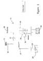
- FIG. 7shows a schematic of a DC electrical power distribution system according to a specific embodiment of the present invention.
- FIG. 1shows a schematic of a typical small size electrical distribution system, generally indicated as 10 , according to the prior art.
- Normal service AC poweris provided by a utility service company 13 and typically enters the facility through a step-down transformer 15 for service up to approximately 300 KVA.
- a standby generator 18is available for rapid startup upon loss of power from the utility company.
- a quick acting transfer switch 21is normally selected to receive power from the utility 13 , but can rapidly transfer to the generator 18 on loss of voltage.
- Typical line voltage in such a small facilityis approximately 120/208 VAC through a single main distribution panel.
- Essential loadssuch as 24
- Critical loadssuch as 30
- An uninterruptible power supply 36usually contains a battery 39 and a pair of power converters.
- a rectifier that converts the AC line power to DC powercontinuously charges the battery 39 and provides regulated power through the inverter to the critical loads 30 .
- the battery 39Upon loss of AC line power, the battery 39 immediately begins to discharge, and the static inverter continues to provide output power to the critical loads 30 .
- FIG. 2shows a schematic of a typical medium size, up to approximately 1,000 KVA, electrical distribution system, according to the prior art.
- normal service AC poweris provided by a utility service company and typically enters the facility through one or more step-down transformers 53 , 54 .
- the electrical distribution system 50will operate in parallel, with redundant components on each side separated by a plurality of normally open breakers, such as 56 , 57 , 58 , 59 , 60 .
- Typical line voltage in such a medium size facilityis approximately 480 VAC through a plurality of distribution panels.
- Building services 65 , 66 and HVAC services 68 , 69may be provided power from either side of the distribution network.
- a pair of uninterruptible power supplies 72 , 73provides stable electrical power to critical load panels 76 , 77 , 78 , 79 .
- An important difference from the small distribution system 10is that the output of the static inverters of the uninterruptible power supply 72 , 73 must be the same as the line voltage, i.e. 480 VAC.
- Another important differenceis that the critical load panels 76 , 77 , 78 , 79 are typically provided power through separate quick-acting, static transfer switches 86 , 87 , 88 , 89 , which are preferentially supplied from one side of the distribution network or the other, and provide power that is stepped down through transformers to 120/208 VAC.
- a plurality of generators 92can provide AC power to the main distribution panels and to the entire network through breakers 56 or 57 .
- critical loads 115receive electrical power from a plurality of uninterruptible power supplies 118 , each having a rectifier, battery storage unit, and static inverter, as described above.
- Multiple isolation breakers 121enable selection of various options for providing reliable electrical power to the critical loads 115 .
- FIG. 4an exemplary high reliability DC power distribution system, indicated generally as 130 , is shown.
- Normal utility power and/or generator power at approximately 277/480 VACis supplied to distribution panels 133 , 134 .
- a plurality of rectifiers, such as 141 , 142 , 143 , and 146 , 147 , 148provide 300 VDC to 600 VDC (500 VDC nominal) to collector busses 151 , 152 .
- Energy storage systems 156 , 157provide rapid emergency DC power to the collector busses 151 , 152 upon loss of AC power to the rectifiers.
- the collector busses 151 , 152feed power to a distribution bus 160 , which may be divided into parallel, redundant busses 163 , 164 , separated by normally open breakers 167 , 168 .
- Distribution bus 160feeds power to both ends of a universal busway 171 having dedicated drops 172 to a plurality of rack mounted DC-to-DC converters 174 or directly to servers or other equipment that operate at the voltage on the universal busway 171 . While the nominal voltage on the universal busway 171 is approximately 500 VDC, high voltage DC power may be approximately 300 VDC to 600 VDC.
- An engine/generatortypically a diesel engine system—(not shown in FIGS. 4-6 ) is on the supply side of the system, typically tied in at the service entrance point for the facility (see FIG. 1 ). Such engine/generator provides rapid startup, emergency electrical power upon loss of power from the service utility.
- FIGS. 5 and 6illustrate enlarged portions of the high reliability DC power distribution system 130 .
- rectifiers 141 , 142 , 143convert utility or generator supplied, three-phase AC power to high voltage DC power.
- the number of rectifiersshould be selected based upon capacity requirements and desired redundancy.
- a suitable devicemay be one or more 20 kW modules, such as model C6497VH-s provided by Schaefer, Inc. of Ashland, Mass.
- AC to DC rectifiersare utilized to act as the front-end power source for a high voltage DC distribution system that supports an entire critical operations environment instead of using a single use rectifier for a specific component.
- the high voltage DC powermay be approximately 300 VDC to 600 VDC (500 VDC nominal). Other appropriate voltages may be used.
- Energy storage system 156comprises flywheel devices 177 , 178 , 179 that provide DC power ride through. That is, upon loss of utility AC power to the rectifiers, the energy storage system 156 provides power to the collector bus 151 while a backup AC power source, such as an engine-powered generator, is brought on line.
- a backup AC power sourcesuch as an engine-powered generator
- the high voltage DC output level from the energy storage system 156is selectable and pre-set to match the nominal voltage on the collector bus 151 .
- the flywheel devices 177 , 178 , 179provide ride-through for the entire distribution system instead of as a DC battery link for a typical uninterruptible power supply. No batteries are required in this invention.
- a suitable flywheel energy storage deviceis manufactured by Pentadyne Power Corporation of Chatsworth, Calif. It employs a carbon-fiber flywheel with an integral synchronous reluctance motor-generator. The flywheel is fully levitated by magnetic bearings to eliminate mechanical losses and includes an internal vacuum pump to minimize aerodynamic losses.
- a plurality of flywheel devices 177 , 178 , 179can be added as desired to increase redundancy and, therefore, reliability, without the need for active paralleling controls, which would be required when multiple AC power systems are paralleled.
- busway 171provides a unique application. Instead of providing an AC distribution system with a single feed, busway 171 provides a DC distribution system that can be fed from multiple DC voltage matched sources. Alternatively, busway 171 can be fed from two separate sources, one on each end, utilizing two bus bars each. The busway 171 is intended to have four separate bus bars—each rated approximately 600 VDC. Two bus bars are fed by one source (labeled A in FIGS. 4 and 6 ) and the other two bus bars are fed by another source (labeled B in FIGS. 4 and 6 ). The drops from the busway 171 can then be selectable from either source.
- busway 171will provide high voltage DC power to equipment rack locations within a compact package having hot swappable/movable connectors that can be fed from separate DC power sources.
- the high voltage DC powermay be approximately 300 VDC to 600 VDC (500 VDC nominal).
- a suitable buswayis the StarLine Track Busway provided by Universal Electric Corporation of Bridgeville, Pa.
- DC-to-DC converters 174take the high voltage DC power from the universal busway 171 and converts to low voltage DC as required at the load rack for critical power load connections. Typical voltage requirements may be 48 VDC, 24 VDC, 9 VDC, 2 VDC, etc. According to the present invention, this unique application provides the necessary equipment voltage at the location of the load itself. Fed from the high voltage DC distribution system, any DC power supply equipment can be fed at any DC voltage utilizing DC-to-DC converters as close as possible to the load itself. This approach greatly increases system efficiency and reliability when redundant systems are used.
- Critical load equipment racks 183are connected to the universal busway 171 through individual DC-to-DC converters 174 .
- Normal three-phase utility service power at approximately 480 VACis provided to the rectifier 186 , which supplies the busway 171 at A.
- Nominal rating for the rectifier rackis 480 VAC input and 520 VDC output.
- An energy storage system 189provides DC power ride through.
- Nominal rating for the energy storage systemis 520 VDC input and 500 VDC output. While the system has been described as nominally 500 VDC distribution, other appropriate voltages, such as approximately 300 VDC to 600 VDC may be used.
- a similarly configured, redundant rectifier rack and energy storage system or other power supplysuch as wind, solar, or fuel cell power, can be provided to the remaining end of the universal busway at B.
Landscapes
- Engineering & Computer Science (AREA)
- Power Engineering (AREA)
- Stand-By Power Supply Arrangements (AREA)
- Direct Current Feeding And Distribution (AREA)
- Supply And Distribution Of Alternating Current (AREA)
Abstract
Description
- Voltage surges and spikes—Times when the voltage on the line is greater than it should be.
- Voltage sags—Times when the voltage on the line is less than it should be.
- Total power failure—Times when a line goes down or a fuse blows somewhere on the grid or in the building.
- Frequency differences—Times when the power is oscillating at something other than 60 Hertz.
- 1) lower component count resulting in higher system efficiency, greater reliability, less maintenance, and lower cost.
- 2) modular and flexible design that allows for system growth.
- 3) energy storage devices that eliminate the need for chemical batteries.
- 4) modular busway system that enables growth and permits redundant DC sources at critical loads.
- 5) DC rated plug-in modules that can be energized on the bus without interruption of critical loads.
- 6) no downstream transfer switches or static switches required.
- 7) DC power distribution eliminates harmonics found on AC systems.
- 8) eliminates the need for stand-alone UPS requirements.
- 9) provides a more efficient interface with “green” power sources that typically produce a DC output, such as wind power, solar power, fuel cells, etc.
Claims (24)
Priority Applications (1)
| Application Number | Priority Date | Filing Date | Title |
|---|---|---|---|
| US11/256,881US7492057B2 (en) | 2004-11-10 | 2005-10-24 | High reliability DC power distribution system |
Applications Claiming Priority (2)
| Application Number | Priority Date | Filing Date | Title |
|---|---|---|---|
| US62667904P | 2004-11-10 | 2004-11-10 | |
| US11/256,881US7492057B2 (en) | 2004-11-10 | 2005-10-24 | High reliability DC power distribution system |
Publications (2)
| Publication Number | Publication Date |
|---|---|
| US20060097578A1 US20060097578A1 (en) | 2006-05-11 |
| US7492057B2true US7492057B2 (en) | 2009-02-17 |
Family
ID=36315603
Family Applications (1)
| Application Number | Title | Priority Date | Filing Date |
|---|---|---|---|
| US11/256,881Active - Reinstated2026-03-21US7492057B2 (en) | 2004-11-10 | 2005-10-24 | High reliability DC power distribution system |
Country Status (1)
| Country | Link |
|---|---|
| US (1) | US7492057B2 (en) |
Cited By (13)
| Publication number | Priority date | Publication date | Assignee | Title |
|---|---|---|---|---|
| US20110148213A1 (en)* | 2009-12-22 | 2011-06-23 | Direct Power Technologies, Inc. | 380 volt direct current power distribution system for information and communication technology systems and facilities |
| US20120134090A1 (en)* | 2010-11-30 | 2012-05-31 | Inventec Corporation | Server computer set |
| US20120200987A1 (en)* | 2011-02-07 | 2012-08-09 | Dell Products L.P. | System and method for structural, modular power distribution in a modular data center |
| CN103490524A (en)* | 2013-09-16 | 2014-01-01 | 江苏大学 | Large-scale hybrid energy storage system and control strategy thereof |
| US8742620B1 (en) | 2012-07-10 | 2014-06-03 | Geneva Holdings, LLC | Electrical cogeneration system and method |
| US8847088B2 (en) | 2011-09-22 | 2014-09-30 | General Electric Company | Cover mounted handle operating mechanism with integrated interlock assembly for a busplug enclosure |
| US8994231B1 (en)* | 2010-12-03 | 2015-03-31 | Exaflop Llc | Medium voltage power distribution |
| US9618991B1 (en) | 2012-09-27 | 2017-04-11 | Google Inc. | Large-scale power back-up for data centers |
| US20180244407A1 (en)* | 2017-02-27 | 2018-08-30 | Hamilton Sundstrand Corporation | Power management and distribution architecture for a space vehicle |
| US10211630B1 (en)* | 2012-09-27 | 2019-02-19 | Google Llc | Data center with large medium voltage domain |
| US10486836B2 (en) | 2016-11-10 | 2019-11-26 | Hamilton Sundstrand Corporaration | Solar powered spacecraft power system |
| US11622468B1 (en) | 2018-06-01 | 2023-04-04 | Worldwide Environmental Services, LLC | Modular data center |
| WO2024052083A1 (en) | 2022-09-05 | 2024-03-14 | Siemens Energy AS | Power distribution system for data centre |
Families Citing this family (13)
| Publication number | Priority date | Publication date | Assignee | Title |
|---|---|---|---|---|
| US7466042B2 (en) | 2005-04-06 | 2008-12-16 | Flexsil, Inc. | Universal DC power |
| US20070029879A1 (en)* | 2005-08-04 | 2007-02-08 | Eldredge James G | Distribution of universal DC power in buildings |
| US8853872B2 (en)* | 2007-02-26 | 2014-10-07 | Google Inc. | Water-based data center |
| EP2467917B1 (en) | 2009-08-21 | 2017-10-11 | Renergyx Pty Limited | Electrical energy distribution system with ride-through capability |
| US7990743B2 (en)* | 2009-10-20 | 2011-08-02 | General Electric Company | System and method for decreasing solar collector system losses |
| US7855906B2 (en)* | 2009-10-26 | 2010-12-21 | General Electric Company | DC bus voltage control for two stage solar converter |
| US8050062B2 (en) | 2010-02-24 | 2011-11-01 | General Electric Company | Method and system to allow for high DC source voltage with lower DC link voltage in a two stage power converter |
| US9778717B2 (en)* | 2014-05-15 | 2017-10-03 | Amazon Technologies, Inc. | Flexible power support redundancy busway system |
| US9857855B2 (en)* | 2014-06-25 | 2018-01-02 | Amazon Technologies, Inc. | Redundant secondary power support system |
| US10090676B2 (en)* | 2015-06-03 | 2018-10-02 | Northrop Grumman Systems Corporation | Aircraft DC power distribution systems and methods |
| US20170126019A1 (en)* | 2015-11-04 | 2017-05-04 | Salt River Project Agricultural Improvement And Power District | Systems and methods for redundant power supply |
| US12074437B2 (en)* | 2020-07-08 | 2024-08-27 | Google Llc | Superconductor network for dynamically reconfigurable power plane |
| CN112018857B (en)* | 2020-09-25 | 2025-03-28 | 深圳市雄韬电源科技股份有限公司 | Battery management system and device |
Citations (31)
| Publication number | Priority date | Publication date | Assignee | Title |
|---|---|---|---|---|
| US4239978A (en) | 1978-03-09 | 1980-12-16 | Robert Bosch Gmbh | Method and system to supply electrical energy to a self-contained electrical network at multiple voltage level, multiple power range, particularly for mobile application |
| US5576940A (en) | 1995-01-09 | 1996-11-19 | General Electric Company | Front-end power converter for distributed power systems |
| US5646458A (en) | 1996-02-22 | 1997-07-08 | Atlas Energy Systems, Inc. | Uninterruptible power system with a flywheel-driven source of standby power |
| US6133716A (en) | 1998-10-23 | 2000-10-17 | Statordyne, Inc. | High-efficiency high-power uninterrupted power system |
| US6175166B1 (en) | 1999-06-14 | 2001-01-16 | Abb Power T&D Company Inc. | System for mitigating voltage disturbances and interruptions for power distribution applications |
| US6239513B1 (en) | 2000-02-24 | 2001-05-29 | Design Power Solutions International | Emergency supplemental power supply for outage protection of critical electric loads |
| US6255743B1 (en) | 1999-05-26 | 2001-07-03 | Active Power, Inc. | Method and apparatus for providing an uninterruptible supply of electric power to a critical load |
| US6304006B1 (en) | 2000-12-28 | 2001-10-16 | Abb T&D Technology Ltd. | Energy management uninterruptible power supply system |
| US6465910B2 (en) | 2001-02-13 | 2002-10-15 | Utc Fuel Cells, Llc | System for providing assured power to a critical load |
| US6463738B1 (en) | 2001-05-21 | 2002-10-15 | Active Power, Inc. | Method and apparatus for providing a continuous supply of electric power |
| US6487096B1 (en) | 1997-09-08 | 2002-11-26 | Capstone Turbine Corporation | Power controller |
| US6507506B1 (en) | 1999-06-09 | 2003-01-14 | Lear Automotive (Eeds) Spain, S. L. | Dual voltage electrical distribution system |
| US20030015873A1 (en) | 2001-01-10 | 2003-01-23 | Claude Khalizadeh | Transient ride-through or load leveling power distribution system |
| US6559559B2 (en) | 2000-05-31 | 2003-05-06 | Sure Power Corporation | Power system utilizing a DC bus |
| US6573626B1 (en) | 1999-10-08 | 2003-06-03 | Piller Gmbh | Apparatus for uninterruptedly supplying power including an electrical machine and a flywheel |
| US20030137196A1 (en) | 2002-01-24 | 2003-07-24 | Abraham Liran | Power supply for providing continuous and regulated energy to the power user |
| US6611068B2 (en) | 1998-05-19 | 2003-08-26 | Sure Power Corporation | Power system |
| US20030160514A1 (en) | 2002-02-27 | 2003-08-28 | Ramamoorthy Rajagopalan | Universal uninterruptible power supply input circuitry and methods for configuring same |
| JP2003339118A (en) | 2002-05-22 | 2003-11-28 | My Way Giken Kk | Distributed power supply system |
| US6657320B1 (en) | 1999-11-03 | 2003-12-02 | Active Power, Inc. | Integrated flywheel uninterruptible power supply system |
| US6683389B2 (en) | 2000-06-30 | 2004-01-27 | Capstone Turbine Corporation | Hybrid electric vehicle DC power generation system |
| US20040070278A1 (en) | 2002-10-15 | 2004-04-15 | Divan Deepakraj M. | Dual feed power supply systems with enhanced power quality |
| US6737763B2 (en) | 2001-12-17 | 2004-05-18 | Cloudshield Technologies, Inc. | Intelligent load sharing with power limiting scheme for multiple power supplies connected to a common load |
| US6746250B2 (en) | 2000-10-05 | 2004-06-08 | Ballard Power Systems Ag | Connection for a distribution network |
| US6762595B2 (en) | 2002-01-21 | 2004-07-13 | Yazaki Corporation | Power distribution system |
| US20040150374A1 (en)* | 2002-11-01 | 2004-08-05 | Rudy Kraus | Apparatus for providing high quality power |
| US20040155527A1 (en) | 2003-02-10 | 2004-08-12 | Bryde Jan Henrik | Distributed power generation, conversion, and storage system |
| US6788029B1 (en) | 2001-11-02 | 2004-09-07 | Christopher W. Gabrys | Flywheel with switched coupling regulator |
| US20040207266A1 (en) | 2003-04-16 | 2004-10-21 | Abel Stephen G. | Standby electrical power generation and storage system and method |
| US20050006598A1 (en) | 2001-10-10 | 2005-01-13 | Asher Pearl | Method and device for aligning a charged particle beam column |
| US20060061213A1 (en)* | 2004-08-24 | 2006-03-23 | Honeywell International | Electrical starting, generation, conversion and distribution system architecture for a more electric vehicle |
- 2005
- 2005-10-24USUS11/256,881patent/US7492057B2/enactiveActive - Reinstated
Patent Citations (31)
| Publication number | Priority date | Publication date | Assignee | Title |
|---|---|---|---|---|
| US4239978A (en) | 1978-03-09 | 1980-12-16 | Robert Bosch Gmbh | Method and system to supply electrical energy to a self-contained electrical network at multiple voltage level, multiple power range, particularly for mobile application |
| US5576940A (en) | 1995-01-09 | 1996-11-19 | General Electric Company | Front-end power converter for distributed power systems |
| US5646458A (en) | 1996-02-22 | 1997-07-08 | Atlas Energy Systems, Inc. | Uninterruptible power system with a flywheel-driven source of standby power |
| US6487096B1 (en) | 1997-09-08 | 2002-11-26 | Capstone Turbine Corporation | Power controller |
| US6611068B2 (en) | 1998-05-19 | 2003-08-26 | Sure Power Corporation | Power system |
| US6133716A (en) | 1998-10-23 | 2000-10-17 | Statordyne, Inc. | High-efficiency high-power uninterrupted power system |
| US6255743B1 (en) | 1999-05-26 | 2001-07-03 | Active Power, Inc. | Method and apparatus for providing an uninterruptible supply of electric power to a critical load |
| US6507506B1 (en) | 1999-06-09 | 2003-01-14 | Lear Automotive (Eeds) Spain, S. L. | Dual voltage electrical distribution system |
| US6175166B1 (en) | 1999-06-14 | 2001-01-16 | Abb Power T&D Company Inc. | System for mitigating voltage disturbances and interruptions for power distribution applications |
| US6573626B1 (en) | 1999-10-08 | 2003-06-03 | Piller Gmbh | Apparatus for uninterruptedly supplying power including an electrical machine and a flywheel |
| US6657320B1 (en) | 1999-11-03 | 2003-12-02 | Active Power, Inc. | Integrated flywheel uninterruptible power supply system |
| US6239513B1 (en) | 2000-02-24 | 2001-05-29 | Design Power Solutions International | Emergency supplemental power supply for outage protection of critical electric loads |
| US6559559B2 (en) | 2000-05-31 | 2003-05-06 | Sure Power Corporation | Power system utilizing a DC bus |
| US6683389B2 (en) | 2000-06-30 | 2004-01-27 | Capstone Turbine Corporation | Hybrid electric vehicle DC power generation system |
| US6746250B2 (en) | 2000-10-05 | 2004-06-08 | Ballard Power Systems Ag | Connection for a distribution network |
| US6304006B1 (en) | 2000-12-28 | 2001-10-16 | Abb T&D Technology Ltd. | Energy management uninterruptible power supply system |
| US20030015873A1 (en) | 2001-01-10 | 2003-01-23 | Claude Khalizadeh | Transient ride-through or load leveling power distribution system |
| US6465910B2 (en) | 2001-02-13 | 2002-10-15 | Utc Fuel Cells, Llc | System for providing assured power to a critical load |
| US6463738B1 (en) | 2001-05-21 | 2002-10-15 | Active Power, Inc. | Method and apparatus for providing a continuous supply of electric power |
| US20050006598A1 (en) | 2001-10-10 | 2005-01-13 | Asher Pearl | Method and device for aligning a charged particle beam column |
| US6788029B1 (en) | 2001-11-02 | 2004-09-07 | Christopher W. Gabrys | Flywheel with switched coupling regulator |
| US6737763B2 (en) | 2001-12-17 | 2004-05-18 | Cloudshield Technologies, Inc. | Intelligent load sharing with power limiting scheme for multiple power supplies connected to a common load |
| US6762595B2 (en) | 2002-01-21 | 2004-07-13 | Yazaki Corporation | Power distribution system |
| US20030137196A1 (en) | 2002-01-24 | 2003-07-24 | Abraham Liran | Power supply for providing continuous and regulated energy to the power user |
| US20030160514A1 (en) | 2002-02-27 | 2003-08-28 | Ramamoorthy Rajagopalan | Universal uninterruptible power supply input circuitry and methods for configuring same |
| JP2003339118A (en) | 2002-05-22 | 2003-11-28 | My Way Giken Kk | Distributed power supply system |
| US20040070278A1 (en) | 2002-10-15 | 2004-04-15 | Divan Deepakraj M. | Dual feed power supply systems with enhanced power quality |
| US20040150374A1 (en)* | 2002-11-01 | 2004-08-05 | Rudy Kraus | Apparatus for providing high quality power |
| US20040155527A1 (en) | 2003-02-10 | 2004-08-12 | Bryde Jan Henrik | Distributed power generation, conversion, and storage system |
| US20040207266A1 (en) | 2003-04-16 | 2004-10-21 | Abel Stephen G. | Standby electrical power generation and storage system and method |
| US20060061213A1 (en)* | 2004-08-24 | 2006-03-23 | Honeywell International | Electrical starting, generation, conversion and distribution system architecture for a more electric vehicle |
Cited By (20)
| Publication number | Priority date | Publication date | Assignee | Title |
|---|---|---|---|---|
| US20110148213A1 (en)* | 2009-12-22 | 2011-06-23 | Direct Power Technologies, Inc. | 380 volt direct current power distribution system for information and communication technology systems and facilities |
| US8638008B2 (en)* | 2009-12-22 | 2014-01-28 | Direct Power Tech Ip, Llc | 380 volt direct current power distribution system for information and communication technology systems and facilities |
| US20120134090A1 (en)* | 2010-11-30 | 2012-05-31 | Inventec Corporation | Server computer set |
| US8994231B1 (en)* | 2010-12-03 | 2015-03-31 | Exaflop Llc | Medium voltage power distribution |
| US20120200987A1 (en)* | 2011-02-07 | 2012-08-09 | Dell Products L.P. | System and method for structural, modular power distribution in a modular data center |
| US8446710B2 (en)* | 2011-02-07 | 2013-05-21 | Dell Products L.P. | System and method for structural, modular power distribution in a modular data center |
| US8847088B2 (en) | 2011-09-22 | 2014-09-30 | General Electric Company | Cover mounted handle operating mechanism with integrated interlock assembly for a busplug enclosure |
| US8742620B1 (en) | 2012-07-10 | 2014-06-03 | Geneva Holdings, LLC | Electrical cogeneration system and method |
| US8957546B2 (en) | 2012-07-10 | 2015-02-17 | Nixon Power Services, Llc | Electrical cogeneration system and method |
| US9618991B1 (en) | 2012-09-27 | 2017-04-11 | Google Inc. | Large-scale power back-up for data centers |
| US10013037B1 (en) | 2012-09-27 | 2018-07-03 | Google Llc | Large-scale power back-up for data centers |
| US10211630B1 (en)* | 2012-09-27 | 2019-02-19 | Google Llc | Data center with large medium voltage domain |
| CN103490524A (en)* | 2013-09-16 | 2014-01-01 | 江苏大学 | Large-scale hybrid energy storage system and control strategy thereof |
| US10486836B2 (en) | 2016-11-10 | 2019-11-26 | Hamilton Sundstrand Corporaration | Solar powered spacecraft power system |
| US20180244407A1 (en)* | 2017-02-27 | 2018-08-30 | Hamilton Sundstrand Corporation | Power management and distribution architecture for a space vehicle |
| US10110000B2 (en)* | 2017-02-27 | 2018-10-23 | Hamilton Sundstrand Corporation | Power management and distribution architecture for a space vehicle |
| US11622468B1 (en) | 2018-06-01 | 2023-04-04 | Worldwide Environmental Services, LLC | Modular data center |
| US11917788B1 (en) | 2018-06-01 | 2024-02-27 | Worldwide Environmental Services, LLC | Modular data center |
| US12356579B1 (en) | 2018-06-01 | 2025-07-08 | Worldwide Environmental Services, LLC | Modular data center |
| WO2024052083A1 (en) | 2022-09-05 | 2024-03-14 | Siemens Energy AS | Power distribution system for data centre |
Also Published As
| Publication number | Publication date |
|---|---|
| US20060097578A1 (en) | 2006-05-11 |
Similar Documents
| Publication | Publication Date | Title |
|---|---|---|
| US7492057B2 (en) | High reliability DC power distribution system | |
| US12132345B2 (en) | Combination wind/solar DC power system | |
| US8638008B2 (en) | 380 volt direct current power distribution system for information and communication technology systems and facilities | |
| US7633181B2 (en) | DC-based data center power architecture | |
| US10873099B1 (en) | Storage system controller | |
| US7141894B2 (en) | Apparatus for providing high quality power | |
| EP2724439B1 (en) | B-side feed for critical power applications | |
| EP0919077B1 (en) | High efficiency lighting system | |
| US11799316B2 (en) | Fuel cell system for information technology loads | |
| US20090079266A1 (en) | Electrical Power Distribution System and Method Thereof | |
| EP2889985A2 (en) | Uninterruptable power supply system and method | |
| AU2016101769A4 (en) | Power system and method | |
| CN110140275A (en) | The UPS device that rack for data center is installed | |
| US20240243606A1 (en) | Systems and Methods for Supplying Uninterruptible Power | |
| US10211630B1 (en) | Data center with large medium voltage domain | |
| CN116316526A (en) | Power supply backup system and method | |
| US12424873B1 (en) | Elevator backup power system and method | |
| JP7470750B2 (en) | Power System | |
| EP4552196A1 (en) | Power distribution system for data centre | |
| GB2622580A (en) | Power distribution system | |
| CN118953085A (en) | A system and method for improving charging efficiency of a light storage and charging system | |
| Warren | Increasing UPS and computer reliability in large installations |
Legal Events
| Date | Code | Title | Description |
|---|---|---|---|
| FPAY | Fee payment | Year of fee payment:4 | |
| REMI | Maintenance fee reminder mailed | ||
| LAPS | Lapse for failure to pay maintenance fees | ||
| FP | Lapsed due to failure to pay maintenance fee | Effective date:20170217 | |
| FEPP | Fee payment procedure | Free format text:SURCHARGE, PETITION TO ACCEPT PYMT AFTER EXP, UNINTENTIONAL. (ORIGINAL EVENT CODE: M2558); ENTITY STATUS OF PATENT OWNER: SMALL ENTITY Free format text:PETITION RELATED TO MAINTENANCE FEES GRANTED (ORIGINAL EVENT CODE: PMFG) Free format text:PETITION RELATED TO MAINTENANCE FEES FILED (ORIGINAL EVENT CODE: PMFP) | |
| MAFP | Maintenance fee payment | Free format text:PAYMENT OF MAINTENANCE FEE, 8TH YR, SMALL ENTITY (ORIGINAL EVENT CODE: M2552) Year of fee payment:8 | |
| PRDP | Patent reinstated due to the acceptance of a late maintenance fee | Effective date:20170925 | |
| STCF | Information on status: patent grant | Free format text:PATENTED CASE | |
| FEPP | Fee payment procedure | Free format text:MAINTENANCE FEE REMINDER MAILED (ORIGINAL EVENT CODE: REM.); ENTITY STATUS OF PATENT OWNER: SMALL ENTITY | |
| LAPS | Lapse for failure to pay maintenance fees | Free format text:PATENT EXPIRED FOR FAILURE TO PAY MAINTENANCE FEES (ORIGINAL EVENT CODE: EXP.); ENTITY STATUS OF PATENT OWNER: SMALL ENTITY | |
| STCH | Information on status: patent discontinuation | Free format text:PATENT EXPIRED DUE TO NONPAYMENT OF MAINTENANCE FEES UNDER 37 CFR 1.362 | |
| FEPP | Fee payment procedure | Free format text:PETITION RELATED TO MAINTENANCE FEES GRANTED (ORIGINAL EVENT CODE: PMFG); ENTITY STATUS OF PATENT OWNER: SMALL ENTITY Free format text:SURCHARGE, PETITION TO ACCEPT PYMT AFTER EXP, UNINTENTIONAL. (ORIGINAL EVENT CODE: M2558); ENTITY STATUS OF PATENT OWNER: SMALL ENTITY Free format text:PETITION RELATED TO MAINTENANCE FEES FILED (ORIGINAL EVENT CODE: PMFP); ENTITY STATUS OF PATENT OWNER: SMALL ENTITY | |
| MAFP | Maintenance fee payment | Free format text:PAYMENT OF MAINTENANCE FEE, 12TH YR, SMALL ENTITY (ORIGINAL EVENT CODE: M2553); ENTITY STATUS OF PATENT OWNER: SMALL ENTITY Year of fee payment:12 | |
| PRDP | Patent reinstated due to the acceptance of a late maintenance fee | Effective date:20210405 | |
| STCF | Information on status: patent grant | Free format text:PATENTED CASE | |
| FP | Lapsed due to failure to pay maintenance fee | Effective date:20210217 |