US7491239B2 - Interior insert ball and dual socket joint - Google Patents
Interior insert ball and dual socket jointDownload PDFInfo
- Publication number
- US7491239B2 US7491239B2US11/207,683US20768305AUS7491239B2US 7491239 B2US7491239 B2US 7491239B2US 20768305 AUS20768305 AUS 20768305AUS 7491239 B2US7491239 B2US 7491239B2
- Authority
- US
- United States
- Prior art keywords
- plate
- depression
- disk
- vertebrae
- placement
- Prior art date
- Legal status (The legal status is an assumption and is not a legal conclusion. Google has not performed a legal analysis and makes no representation as to the accuracy of the status listed.)
- Expired - Fee Related, expires
Links
- 230000009977dual effectEffects0.000title1
- 239000007943implantSubstances0.000claimsabstractdescription42
- 239000000463materialSubstances0.000claimsdescription17
- 239000012858resilient materialSubstances0.000claimsdescription10
- 238000000926separation methodMethods0.000claimsdescription3
- 238000007789sealingMethods0.000claims1
- 230000006835compressionEffects0.000abstractdescription4
- 238000007906compressionMethods0.000abstractdescription4
- 230000007246mechanismEffects0.000abstractdescription4
- 229910052751metalInorganic materials0.000description6
- 239000002184metalSubstances0.000description6
- 239000012528membraneSubstances0.000description5
- 229920000642polymerPolymers0.000description5
- PNEYBMLMFCGWSK-UHFFFAOYSA-NAluminaChemical compound[O-2].[O-2].[O-2].[Al+3].[Al+3]PNEYBMLMFCGWSK-UHFFFAOYSA-N0.000description4
- 229910052581Si3N4Inorganic materials0.000description4
- 238000005452bendingMethods0.000description4
- 210000000988bone and boneAnatomy0.000description4
- HQVNEWCFYHHQES-UHFFFAOYSA-Nsilicon nitrideChemical compoundN12[Si]34N5[Si]62N3[Si]51N64HQVNEWCFYHHQES-UHFFFAOYSA-N0.000description4
- 230000009471actionEffects0.000description3
- 229910045601alloyInorganic materials0.000description3
- 239000000956alloySubstances0.000description3
- 239000000919ceramicSubstances0.000description3
- HBMJWWWQQXIZIP-UHFFFAOYSA-Nsilicon carbideChemical compound[Si+]#[C-]HBMJWWWQQXIZIP-UHFFFAOYSA-N0.000description3
- 229910010271silicon carbideInorganic materials0.000description3
- IJGRMHOSHXDMSA-UHFFFAOYSA-NAtomic nitrogenChemical compoundN#NIJGRMHOSHXDMSA-UHFFFAOYSA-N0.000description2
- 229910000684Cobalt-chromeInorganic materials0.000description2
- RTAQQCXQSZGOHL-UHFFFAOYSA-NTitaniumChemical compound[Ti]RTAQQCXQSZGOHL-UHFFFAOYSA-N0.000description2
- 238000005524ceramic coatingMethods0.000description2
- 229910010293ceramic materialInorganic materials0.000description2
- 238000000576coating methodMethods0.000description2
- 239000010952cobalt-chromeSubstances0.000description2
- 230000000694effectsEffects0.000description2
- 238000002595magnetic resonance imagingMethods0.000description2
- 239000011159matrix materialSubstances0.000description2
- 150000002739metalsChemical class0.000description2
- 238000000034methodMethods0.000description2
- 230000004048modificationEffects0.000description2
- 238000012986modificationMethods0.000description2
- -1respectivelyInorganic materials0.000description2
- 239000010935stainless steelSubstances0.000description2
- 229910001220stainless steelInorganic materials0.000description2
- 229910052719titaniumInorganic materials0.000description2
- 239000010936titaniumSubstances0.000description2
- VUEGYUOUAAVYAS-JGGQBBKZSA-N(6ar,9s,10ar)-9-(dimethylsulfamoylamino)-7-methyl-6,6a,8,9,10,10a-hexahydro-4h-indolo[4,3-fg]quinolineChemical compoundC1=CC([C@H]2C[C@@H](CN(C)[C@@H]2C2)NS(=O)(=O)N(C)C)=C3C2=CNC3=C1VUEGYUOUAAVYAS-JGGQBBKZSA-N0.000description1
- VYZAMTAEIAYCRO-UHFFFAOYSA-NChromiumChemical compound[Cr]VYZAMTAEIAYCRO-UHFFFAOYSA-N0.000description1
- 239000004698PolyethyleneSubstances0.000description1
- 229910001069Ti alloyInorganic materials0.000description1
- 210000003484anatomyAnatomy0.000description1
- 229910052804chromiumInorganic materials0.000description1
- 239000011651chromiumSubstances0.000description1
- 239000000084colloidal systemSubstances0.000description1
- 238000005260corrosionMethods0.000description1
- 230000007797corrosionEffects0.000description1
- 238000002405diagnostic procedureMethods0.000description1
- 238000002513implantationMethods0.000description1
- 238000003780insertionMethods0.000description1
- 230000037431insertionEffects0.000description1
- 230000003993interactionEffects0.000description1
- 210000003041ligamentAnatomy0.000description1
- 238000004519manufacturing processMethods0.000description1
- 210000003205muscleAnatomy0.000description1
- 229910052757nitrogenInorganic materials0.000description1
- 230000000399orthopedic effectEffects0.000description1
- 239000002245particleSubstances0.000description1
- 229920000573polyethylenePolymers0.000description1
- 229920001296polysiloxanePolymers0.000description1
- 230000008439repair processEffects0.000description1
- 239000007787solidSubstances0.000description1
- 238000001356surgical procedureMethods0.000description1
- 210000002435tendonAnatomy0.000description1
- 210000001519tissueAnatomy0.000description1
Images


Classifications
- A—HUMAN NECESSITIES
- A61—MEDICAL OR VETERINARY SCIENCE; HYGIENE
- A61F—FILTERS IMPLANTABLE INTO BLOOD VESSELS; PROSTHESES; DEVICES PROVIDING PATENCY TO, OR PREVENTING COLLAPSING OF, TUBULAR STRUCTURES OF THE BODY, e.g. STENTS; ORTHOPAEDIC, NURSING OR CONTRACEPTIVE DEVICES; FOMENTATION; TREATMENT OR PROTECTION OF EYES OR EARS; BANDAGES, DRESSINGS OR ABSORBENT PADS; FIRST-AID KITS
- A61F2/00—Filters implantable into blood vessels; Prostheses, i.e. artificial substitutes or replacements for parts of the body; Appliances for connecting them with the body; Devices providing patency to, or preventing collapsing of, tubular structures of the body, e.g. stents
- A61F2/02—Prostheses implantable into the body
- A61F2/30—Joints
- A61F2/44—Joints for the spine, e.g. vertebrae, spinal discs
- A61F2/442—Intervertebral or spinal discs, e.g. resilient
- A61F2/4425—Intervertebral or spinal discs, e.g. resilient made of articulated components
- A—HUMAN NECESSITIES
- A61—MEDICAL OR VETERINARY SCIENCE; HYGIENE
- A61F—FILTERS IMPLANTABLE INTO BLOOD VESSELS; PROSTHESES; DEVICES PROVIDING PATENCY TO, OR PREVENTING COLLAPSING OF, TUBULAR STRUCTURES OF THE BODY, e.g. STENTS; ORTHOPAEDIC, NURSING OR CONTRACEPTIVE DEVICES; FOMENTATION; TREATMENT OR PROTECTION OF EYES OR EARS; BANDAGES, DRESSINGS OR ABSORBENT PADS; FIRST-AID KITS
- A61F2/00—Filters implantable into blood vessels; Prostheses, i.e. artificial substitutes or replacements for parts of the body; Appliances for connecting them with the body; Devices providing patency to, or preventing collapsing of, tubular structures of the body, e.g. stents
- A61F2/02—Prostheses implantable into the body
- A61F2/30—Joints
- A61F2/30721—Accessories
- A61F2/30742—Bellows or hose-like seals; Sealing membranes
- A—HUMAN NECESSITIES
- A61—MEDICAL OR VETERINARY SCIENCE; HYGIENE
- A61F—FILTERS IMPLANTABLE INTO BLOOD VESSELS; PROSTHESES; DEVICES PROVIDING PATENCY TO, OR PREVENTING COLLAPSING OF, TUBULAR STRUCTURES OF THE BODY, e.g. STENTS; ORTHOPAEDIC, NURSING OR CONTRACEPTIVE DEVICES; FOMENTATION; TREATMENT OR PROTECTION OF EYES OR EARS; BANDAGES, DRESSINGS OR ABSORBENT PADS; FIRST-AID KITS
- A61F2/00—Filters implantable into blood vessels; Prostheses, i.e. artificial substitutes or replacements for parts of the body; Appliances for connecting them with the body; Devices providing patency to, or preventing collapsing of, tubular structures of the body, e.g. stents
- A61F2/02—Prostheses implantable into the body
- A61F2/30—Joints
- A61F2002/30001—Additional features of subject-matter classified in A61F2/28, A61F2/30 and subgroups thereof
- A61F2002/30108—Shapes
- A61F2002/30199—Three-dimensional shapes
- A61F2002/30242—Three-dimensional shapes spherical
- A—HUMAN NECESSITIES
- A61—MEDICAL OR VETERINARY SCIENCE; HYGIENE
- A61F—FILTERS IMPLANTABLE INTO BLOOD VESSELS; PROSTHESES; DEVICES PROVIDING PATENCY TO, OR PREVENTING COLLAPSING OF, TUBULAR STRUCTURES OF THE BODY, e.g. STENTS; ORTHOPAEDIC, NURSING OR CONTRACEPTIVE DEVICES; FOMENTATION; TREATMENT OR PROTECTION OF EYES OR EARS; BANDAGES, DRESSINGS OR ABSORBENT PADS; FIRST-AID KITS
- A61F2/00—Filters implantable into blood vessels; Prostheses, i.e. artificial substitutes or replacements for parts of the body; Appliances for connecting them with the body; Devices providing patency to, or preventing collapsing of, tubular structures of the body, e.g. stents
- A61F2/02—Prostheses implantable into the body
- A61F2/30—Joints
- A61F2002/30001—Additional features of subject-matter classified in A61F2/28, A61F2/30 and subgroups thereof
- A61F2002/30316—The prosthesis having different structural features at different locations within the same prosthesis; Connections between prosthetic parts; Special structural features of bone or joint prostheses not otherwise provided for
- A61F2002/30329—Connections or couplings between prosthetic parts, e.g. between modular parts; Connecting elements
- A61F2002/30331—Connections or couplings between prosthetic parts, e.g. between modular parts; Connecting elements made by longitudinally pushing a protrusion into a complementarily-shaped recess, e.g. held by friction fit
- A61F2002/30362—Connections or couplings between prosthetic parts, e.g. between modular parts; Connecting elements made by longitudinally pushing a protrusion into a complementarily-shaped recess, e.g. held by friction fit with possibility of relative movement between the protrusion and the recess
- A61F2002/3037—Translation along the common longitudinal axis, e.g. piston
- A61F2002/30372—Translation along the common longitudinal axis, e.g. piston with additional means for limiting said translation
- A—HUMAN NECESSITIES
- A61—MEDICAL OR VETERINARY SCIENCE; HYGIENE
- A61F—FILTERS IMPLANTABLE INTO BLOOD VESSELS; PROSTHESES; DEVICES PROVIDING PATENCY TO, OR PREVENTING COLLAPSING OF, TUBULAR STRUCTURES OF THE BODY, e.g. STENTS; ORTHOPAEDIC, NURSING OR CONTRACEPTIVE DEVICES; FOMENTATION; TREATMENT OR PROTECTION OF EYES OR EARS; BANDAGES, DRESSINGS OR ABSORBENT PADS; FIRST-AID KITS
- A61F2/00—Filters implantable into blood vessels; Prostheses, i.e. artificial substitutes or replacements for parts of the body; Appliances for connecting them with the body; Devices providing patency to, or preventing collapsing of, tubular structures of the body, e.g. stents
- A61F2/02—Prostheses implantable into the body
- A61F2/30—Joints
- A61F2002/30001—Additional features of subject-matter classified in A61F2/28, A61F2/30 and subgroups thereof
- A61F2002/30316—The prosthesis having different structural features at different locations within the same prosthesis; Connections between prosthetic parts; Special structural features of bone or joint prostheses not otherwise provided for
- A61F2002/30329—Connections or couplings between prosthetic parts, e.g. between modular parts; Connecting elements
- A61F2002/30426—Bayonet coupling
- A—HUMAN NECESSITIES
- A61—MEDICAL OR VETERINARY SCIENCE; HYGIENE
- A61F—FILTERS IMPLANTABLE INTO BLOOD VESSELS; PROSTHESES; DEVICES PROVIDING PATENCY TO, OR PREVENTING COLLAPSING OF, TUBULAR STRUCTURES OF THE BODY, e.g. STENTS; ORTHOPAEDIC, NURSING OR CONTRACEPTIVE DEVICES; FOMENTATION; TREATMENT OR PROTECTION OF EYES OR EARS; BANDAGES, DRESSINGS OR ABSORBENT PADS; FIRST-AID KITS
- A61F2/00—Filters implantable into blood vessels; Prostheses, i.e. artificial substitutes or replacements for parts of the body; Appliances for connecting them with the body; Devices providing patency to, or preventing collapsing of, tubular structures of the body, e.g. stents
- A61F2/02—Prostheses implantable into the body
- A61F2/30—Joints
- A61F2002/30001—Additional features of subject-matter classified in A61F2/28, A61F2/30 and subgroups thereof
- A61F2002/30316—The prosthesis having different structural features at different locations within the same prosthesis; Connections between prosthetic parts; Special structural features of bone or joint prostheses not otherwise provided for
- A61F2002/30535—Special structural features of bone or joint prostheses not otherwise provided for
- A61F2002/30563—Special structural features of bone or joint prostheses not otherwise provided for having elastic means or damping means, different from springs, e.g. including an elastomeric core or shock absorbers
- A—HUMAN NECESSITIES
- A61—MEDICAL OR VETERINARY SCIENCE; HYGIENE
- A61F—FILTERS IMPLANTABLE INTO BLOOD VESSELS; PROSTHESES; DEVICES PROVIDING PATENCY TO, OR PREVENTING COLLAPSING OF, TUBULAR STRUCTURES OF THE BODY, e.g. STENTS; ORTHOPAEDIC, NURSING OR CONTRACEPTIVE DEVICES; FOMENTATION; TREATMENT OR PROTECTION OF EYES OR EARS; BANDAGES, DRESSINGS OR ABSORBENT PADS; FIRST-AID KITS
- A61F2/00—Filters implantable into blood vessels; Prostheses, i.e. artificial substitutes or replacements for parts of the body; Appliances for connecting them with the body; Devices providing patency to, or preventing collapsing of, tubular structures of the body, e.g. stents
- A61F2/02—Prostheses implantable into the body
- A61F2/30—Joints
- A61F2002/30001—Additional features of subject-matter classified in A61F2/28, A61F2/30 and subgroups thereof
- A61F2002/30316—The prosthesis having different structural features at different locations within the same prosthesis; Connections between prosthetic parts; Special structural features of bone or joint prostheses not otherwise provided for
- A61F2002/30535—Special structural features of bone or joint prostheses not otherwise provided for
- A61F2002/30565—Special structural features of bone or joint prostheses not otherwise provided for having spring elements
- A—HUMAN NECESSITIES
- A61—MEDICAL OR VETERINARY SCIENCE; HYGIENE
- A61F—FILTERS IMPLANTABLE INTO BLOOD VESSELS; PROSTHESES; DEVICES PROVIDING PATENCY TO, OR PREVENTING COLLAPSING OF, TUBULAR STRUCTURES OF THE BODY, e.g. STENTS; ORTHOPAEDIC, NURSING OR CONTRACEPTIVE DEVICES; FOMENTATION; TREATMENT OR PROTECTION OF EYES OR EARS; BANDAGES, DRESSINGS OR ABSORBENT PADS; FIRST-AID KITS
- A61F2/00—Filters implantable into blood vessels; Prostheses, i.e. artificial substitutes or replacements for parts of the body; Appliances for connecting them with the body; Devices providing patency to, or preventing collapsing of, tubular structures of the body, e.g. stents
- A61F2/02—Prostheses implantable into the body
- A61F2/30—Joints
- A61F2002/30001—Additional features of subject-matter classified in A61F2/28, A61F2/30 and subgroups thereof
- A61F2002/30316—The prosthesis having different structural features at different locations within the same prosthesis; Connections between prosthetic parts; Special structural features of bone or joint prostheses not otherwise provided for
- A61F2002/30535—Special structural features of bone or joint prostheses not otherwise provided for
- A61F2002/30574—Special structural features of bone or joint prostheses not otherwise provided for with an integral complete or partial collar or flange
- A—HUMAN NECESSITIES
- A61—MEDICAL OR VETERINARY SCIENCE; HYGIENE
- A61F—FILTERS IMPLANTABLE INTO BLOOD VESSELS; PROSTHESES; DEVICES PROVIDING PATENCY TO, OR PREVENTING COLLAPSING OF, TUBULAR STRUCTURES OF THE BODY, e.g. STENTS; ORTHOPAEDIC, NURSING OR CONTRACEPTIVE DEVICES; FOMENTATION; TREATMENT OR PROTECTION OF EYES OR EARS; BANDAGES, DRESSINGS OR ABSORBENT PADS; FIRST-AID KITS
- A61F2/00—Filters implantable into blood vessels; Prostheses, i.e. artificial substitutes or replacements for parts of the body; Appliances for connecting them with the body; Devices providing patency to, or preventing collapsing of, tubular structures of the body, e.g. stents
- A61F2/02—Prostheses implantable into the body
- A61F2/30—Joints
- A61F2002/30001—Additional features of subject-matter classified in A61F2/28, A61F2/30 and subgroups thereof
- A61F2002/30316—The prosthesis having different structural features at different locations within the same prosthesis; Connections between prosthetic parts; Special structural features of bone or joint prostheses not otherwise provided for
- A61F2002/30535—Special structural features of bone or joint prostheses not otherwise provided for
- A61F2002/30576—Special structural features of bone or joint prostheses not otherwise provided for with extending fixation tabs
- A61F2002/30578—Special structural features of bone or joint prostheses not otherwise provided for with extending fixation tabs having apertures, e.g. for receiving fixation screws
- A—HUMAN NECESSITIES
- A61—MEDICAL OR VETERINARY SCIENCE; HYGIENE
- A61F—FILTERS IMPLANTABLE INTO BLOOD VESSELS; PROSTHESES; DEVICES PROVIDING PATENCY TO, OR PREVENTING COLLAPSING OF, TUBULAR STRUCTURES OF THE BODY, e.g. STENTS; ORTHOPAEDIC, NURSING OR CONTRACEPTIVE DEVICES; FOMENTATION; TREATMENT OR PROTECTION OF EYES OR EARS; BANDAGES, DRESSINGS OR ABSORBENT PADS; FIRST-AID KITS
- A61F2/00—Filters implantable into blood vessels; Prostheses, i.e. artificial substitutes or replacements for parts of the body; Appliances for connecting them with the body; Devices providing patency to, or preventing collapsing of, tubular structures of the body, e.g. stents
- A61F2/02—Prostheses implantable into the body
- A61F2/30—Joints
- A61F2002/30001—Additional features of subject-matter classified in A61F2/28, A61F2/30 and subgroups thereof
- A61F2002/30316—The prosthesis having different structural features at different locations within the same prosthesis; Connections between prosthetic parts; Special structural features of bone or joint prostheses not otherwise provided for
- A61F2002/30535—Special structural features of bone or joint prostheses not otherwise provided for
- A61F2002/30604—Special structural features of bone or joint prostheses not otherwise provided for modular
- A61F2002/30616—Sets comprising a plurality of prosthetic parts of different sizes or orientations
- A—HUMAN NECESSITIES
- A61—MEDICAL OR VETERINARY SCIENCE; HYGIENE
- A61F—FILTERS IMPLANTABLE INTO BLOOD VESSELS; PROSTHESES; DEVICES PROVIDING PATENCY TO, OR PREVENTING COLLAPSING OF, TUBULAR STRUCTURES OF THE BODY, e.g. STENTS; ORTHOPAEDIC, NURSING OR CONTRACEPTIVE DEVICES; FOMENTATION; TREATMENT OR PROTECTION OF EYES OR EARS; BANDAGES, DRESSINGS OR ABSORBENT PADS; FIRST-AID KITS
- A61F2/00—Filters implantable into blood vessels; Prostheses, i.e. artificial substitutes or replacements for parts of the body; Appliances for connecting them with the body; Devices providing patency to, or preventing collapsing of, tubular structures of the body, e.g. stents
- A61F2/02—Prostheses implantable into the body
- A61F2/30—Joints
- A61F2002/30001—Additional features of subject-matter classified in A61F2/28, A61F2/30 and subgroups thereof
- A61F2002/30621—Features concerning the anatomical functioning or articulation of the prosthetic joint
- A61F2002/30649—Ball-and-socket joints
- A61F2002/30663—Ball-and-socket joints multiaxial, e.g. biaxial; multipolar, e.g. bipolar or having an intermediate shell articulating between the ball and the socket
- A—HUMAN NECESSITIES
- A61—MEDICAL OR VETERINARY SCIENCE; HYGIENE
- A61F—FILTERS IMPLANTABLE INTO BLOOD VESSELS; PROSTHESES; DEVICES PROVIDING PATENCY TO, OR PREVENTING COLLAPSING OF, TUBULAR STRUCTURES OF THE BODY, e.g. STENTS; ORTHOPAEDIC, NURSING OR CONTRACEPTIVE DEVICES; FOMENTATION; TREATMENT OR PROTECTION OF EYES OR EARS; BANDAGES, DRESSINGS OR ABSORBENT PADS; FIRST-AID KITS
- A61F2/00—Filters implantable into blood vessels; Prostheses, i.e. artificial substitutes or replacements for parts of the body; Appliances for connecting them with the body; Devices providing patency to, or preventing collapsing of, tubular structures of the body, e.g. stents
- A61F2/02—Prostheses implantable into the body
- A61F2/30—Joints
- A61F2/30767—Special external or bone-contacting surface, e.g. coating for improving bone ingrowth
- A61F2/30771—Special external or bone-contacting surface, e.g. coating for improving bone ingrowth applied in original prostheses, e.g. holes or grooves
- A61F2002/30841—Sharp anchoring protrusions for impaction into the bone, e.g. sharp pins, spikes
- A—HUMAN NECESSITIES
- A61—MEDICAL OR VETERINARY SCIENCE; HYGIENE
- A61F—FILTERS IMPLANTABLE INTO BLOOD VESSELS; PROSTHESES; DEVICES PROVIDING PATENCY TO, OR PREVENTING COLLAPSING OF, TUBULAR STRUCTURES OF THE BODY, e.g. STENTS; ORTHOPAEDIC, NURSING OR CONTRACEPTIVE DEVICES; FOMENTATION; TREATMENT OR PROTECTION OF EYES OR EARS; BANDAGES, DRESSINGS OR ABSORBENT PADS; FIRST-AID KITS
- A61F2/00—Filters implantable into blood vessels; Prostheses, i.e. artificial substitutes or replacements for parts of the body; Appliances for connecting them with the body; Devices providing patency to, or preventing collapsing of, tubular structures of the body, e.g. stents
- A61F2/02—Prostheses implantable into the body
- A61F2/30—Joints
- A61F2/30767—Special external or bone-contacting surface, e.g. coating for improving bone ingrowth
- A61F2002/30932—Special external or bone-contacting surface, e.g. coating for improving bone ingrowth for retarding or preventing ingrowth of bone tissue
- A—HUMAN NECESSITIES
- A61—MEDICAL OR VETERINARY SCIENCE; HYGIENE
- A61F—FILTERS IMPLANTABLE INTO BLOOD VESSELS; PROSTHESES; DEVICES PROVIDING PATENCY TO, OR PREVENTING COLLAPSING OF, TUBULAR STRUCTURES OF THE BODY, e.g. STENTS; ORTHOPAEDIC, NURSING OR CONTRACEPTIVE DEVICES; FOMENTATION; TREATMENT OR PROTECTION OF EYES OR EARS; BANDAGES, DRESSINGS OR ABSORBENT PADS; FIRST-AID KITS
- A61F2/00—Filters implantable into blood vessels; Prostheses, i.e. artificial substitutes or replacements for parts of the body; Appliances for connecting them with the body; Devices providing patency to, or preventing collapsing of, tubular structures of the body, e.g. stents
- A61F2/02—Prostheses implantable into the body
- A61F2/30—Joints
- A61F2/44—Joints for the spine, e.g. vertebrae, spinal discs
- A61F2/442—Intervertebral or spinal discs, e.g. resilient
- A61F2/4425—Intervertebral or spinal discs, e.g. resilient made of articulated components
- A61F2002/443—Intervertebral or spinal discs, e.g. resilient made of articulated components having two transversal endplates and at least one intermediate component
- A—HUMAN NECESSITIES
- A61—MEDICAL OR VETERINARY SCIENCE; HYGIENE
- A61F—FILTERS IMPLANTABLE INTO BLOOD VESSELS; PROSTHESES; DEVICES PROVIDING PATENCY TO, OR PREVENTING COLLAPSING OF, TUBULAR STRUCTURES OF THE BODY, e.g. STENTS; ORTHOPAEDIC, NURSING OR CONTRACEPTIVE DEVICES; FOMENTATION; TREATMENT OR PROTECTION OF EYES OR EARS; BANDAGES, DRESSINGS OR ABSORBENT PADS; FIRST-AID KITS
- A61F2220/00—Fixations or connections for prostheses classified in groups A61F2/00 - A61F2/26 or A61F2/82 or A61F9/00 or A61F11/00 or subgroups thereof
- A61F2220/0025—Connections or couplings between prosthetic parts, e.g. between modular parts; Connecting elements
- A61F2220/0033—Connections or couplings between prosthetic parts, e.g. between modular parts; Connecting elements made by longitudinally pushing a protrusion into a complementary-shaped recess, e.g. held by friction fit
- A—HUMAN NECESSITIES
- A61—MEDICAL OR VETERINARY SCIENCE; HYGIENE
- A61F—FILTERS IMPLANTABLE INTO BLOOD VESSELS; PROSTHESES; DEVICES PROVIDING PATENCY TO, OR PREVENTING COLLAPSING OF, TUBULAR STRUCTURES OF THE BODY, e.g. STENTS; ORTHOPAEDIC, NURSING OR CONTRACEPTIVE DEVICES; FOMENTATION; TREATMENT OR PROTECTION OF EYES OR EARS; BANDAGES, DRESSINGS OR ABSORBENT PADS; FIRST-AID KITS
- A61F2230/00—Geometry of prostheses classified in groups A61F2/00 - A61F2/26 or A61F2/82 or A61F9/00 or A61F11/00 or subgroups thereof
- A61F2230/0063—Three-dimensional shapes
- A61F2230/0071—Three-dimensional shapes spherical
- A—HUMAN NECESSITIES
- A61—MEDICAL OR VETERINARY SCIENCE; HYGIENE
- A61F—FILTERS IMPLANTABLE INTO BLOOD VESSELS; PROSTHESES; DEVICES PROVIDING PATENCY TO, OR PREVENTING COLLAPSING OF, TUBULAR STRUCTURES OF THE BODY, e.g. STENTS; ORTHOPAEDIC, NURSING OR CONTRACEPTIVE DEVICES; FOMENTATION; TREATMENT OR PROTECTION OF EYES OR EARS; BANDAGES, DRESSINGS OR ABSORBENT PADS; FIRST-AID KITS
- A61F2310/00—Prostheses classified in A61F2/28 or A61F2/30 - A61F2/44 being constructed from or coated with a particular material
- A61F2310/00005—The prosthesis being constructed from a particular material
- A61F2310/00011—Metals or alloys
- A—HUMAN NECESSITIES
- A61—MEDICAL OR VETERINARY SCIENCE; HYGIENE
- A61F—FILTERS IMPLANTABLE INTO BLOOD VESSELS; PROSTHESES; DEVICES PROVIDING PATENCY TO, OR PREVENTING COLLAPSING OF, TUBULAR STRUCTURES OF THE BODY, e.g. STENTS; ORTHOPAEDIC, NURSING OR CONTRACEPTIVE DEVICES; FOMENTATION; TREATMENT OR PROTECTION OF EYES OR EARS; BANDAGES, DRESSINGS OR ABSORBENT PADS; FIRST-AID KITS
- A61F2310/00—Prostheses classified in A61F2/28 or A61F2/30 - A61F2/44 being constructed from or coated with a particular material
- A61F2310/00005—The prosthesis being constructed from a particular material
- A61F2310/00179—Ceramics or ceramic-like structures
- A61F2310/00185—Ceramics or ceramic-like structures based on metal oxides
- A61F2310/00203—Ceramics or ceramic-like structures based on metal oxides containing alumina or aluminium oxide
- A—HUMAN NECESSITIES
- A61—MEDICAL OR VETERINARY SCIENCE; HYGIENE
- A61F—FILTERS IMPLANTABLE INTO BLOOD VESSELS; PROSTHESES; DEVICES PROVIDING PATENCY TO, OR PREVENTING COLLAPSING OF, TUBULAR STRUCTURES OF THE BODY, e.g. STENTS; ORTHOPAEDIC, NURSING OR CONTRACEPTIVE DEVICES; FOMENTATION; TREATMENT OR PROTECTION OF EYES OR EARS; BANDAGES, DRESSINGS OR ABSORBENT PADS; FIRST-AID KITS
- A61F2310/00—Prostheses classified in A61F2/28 or A61F2/30 - A61F2/44 being constructed from or coated with a particular material
- A61F2310/00005—The prosthesis being constructed from a particular material
- A61F2310/00179—Ceramics or ceramic-like structures
- A61F2310/00269—Ceramics or ceramic-like structures based on metal carbides
- A61F2310/00281—Ceramics or ceramic-like structures based on metal carbides containing silicon carbide
- A—HUMAN NECESSITIES
- A61—MEDICAL OR VETERINARY SCIENCE; HYGIENE
- A61F—FILTERS IMPLANTABLE INTO BLOOD VESSELS; PROSTHESES; DEVICES PROVIDING PATENCY TO, OR PREVENTING COLLAPSING OF, TUBULAR STRUCTURES OF THE BODY, e.g. STENTS; ORTHOPAEDIC, NURSING OR CONTRACEPTIVE DEVICES; FOMENTATION; TREATMENT OR PROTECTION OF EYES OR EARS; BANDAGES, DRESSINGS OR ABSORBENT PADS; FIRST-AID KITS
- A61F2310/00—Prostheses classified in A61F2/28 or A61F2/30 - A61F2/44 being constructed from or coated with a particular material
- A61F2310/00005—The prosthesis being constructed from a particular material
- A61F2310/00179—Ceramics or ceramic-like structures
- A61F2310/00299—Ceramics or ceramic-like structures based on metal nitrides
- A61F2310/00317—Ceramics or ceramic-like structures based on metal nitrides containing silicon nitride
- A—HUMAN NECESSITIES
- A61—MEDICAL OR VETERINARY SCIENCE; HYGIENE
- A61F—FILTERS IMPLANTABLE INTO BLOOD VESSELS; PROSTHESES; DEVICES PROVIDING PATENCY TO, OR PREVENTING COLLAPSING OF, TUBULAR STRUCTURES OF THE BODY, e.g. STENTS; ORTHOPAEDIC, NURSING OR CONTRACEPTIVE DEVICES; FOMENTATION; TREATMENT OR PROTECTION OF EYES OR EARS; BANDAGES, DRESSINGS OR ABSORBENT PADS; FIRST-AID KITS
- A61F2310/00—Prostheses classified in A61F2/28 or A61F2/30 - A61F2/44 being constructed from or coated with a particular material
- A61F2310/00389—The prosthesis being coated or covered with a particular material
- A61F2310/00592—Coating or prosthesis-covering structure made of ceramics or of ceramic-like compounds
Definitions
- This inventionrelates to orthopedic surgery and, in particular, spinal implants for replacement of ruptured or excised spinal disks.
- U.S. Pat. No. 4,759,769 to Hedman et aldiscloses an artificial disk device in which two plates are attached to the adjacent vertebrae by bone screws inserted through flanges on the plates. A spring biasing mechanism is captured between the plates to simulate the actions of the natural disk material.
- U.S. Pat. No. 5,246,458 to Graham and U.S. Pat. No. 6,228,118 to Gordondisclose other intervertebral implants with arcuate flanges used to connect the device to adjacent vertebra. Graham also teaches a resilient structure.
- the inventionis directed to a spinal implant for insertion between adjacent vertebrae to function as an disk prosthesis.
- the prosthesisis formed from two plates fastened to adjacent vertebrae facing each other.
- the facing sides of the plateseach have a depending skirt formed as concentric arcs of about 90 degrees.
- the skirtsare either bowed or tapered in the axial direction.
- a depressionis centrally located between the arcs of both plates.
- a spring mechanismis centrally located on one or both of the plates to provide axial compression.
- a sphere or ballis placed in the central depression of one of the plates.
- the platesare oriented to each other with the concentric arcs of each interrupted skirt at 90 degrees and the ball is engaged in the depression of the other plate.
- the platesare then rotated about 90 degrees and the opposed arcs of one plate interlock with the opposed arcs of the other plate to prevent separation in the axial direction.
- one plateforms a receptacle for a dynamic socket to be inserted and fixed in place internally.
- FIG. 1is an exploded perspective of the disassembled cage of this invention
- FIG. 2is an exploded perspective of a disassembled plate of the spinal implant of FIG. 1 ;
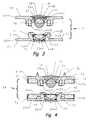
- FIG. 3is an exploded cross section of the assembled implant of this invention.
- FIG. 4is an exploded cross section of another embodiment of the assembled implant of this invention.
- FIG. 5is a perspective of the embodiment shown in FIG. 6 ;
- FIG. 6is an exploded cross section of another embodiment of the assembled implant of this invention.
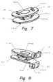
- FIG. 7is a perspective of the assembled implant of this invention showing a bone attachment device
- FIG. 8is a perspective of the assembled implant of this invention showing another bone attachment device.
- the spinal implant 10shown in FIG. 1 , has three major components, an upper plate 11 , a lower plate 12 and a universally rotatable sphere or ball 50 .
- the upper plate 11 and the lower plate 12form a cage when assembled with the ball 50 captured for universal movement within the interior of the cage.
- Both upper plate 11 and lower plate 12have a plan form substantially the size and shape of the end wall of the vertebra between which the implant will be placed to produce the maximum area of contact between the implant and the vertebra for stability and support.
- different sized platesare necessary because of the difference in size of vertebra within regions of the spinal column and the different sizes or ages of patients.
- the upper plate 11has a planar surface 14 for contact with the end wall of a vertebra and an opposite disk surface 15 .
- an interrupted skirt 16with opposed arcs 17 and 18 .
- the arcsare approximately 180 degrees apart at their centers and extend about 90 degrees.
- the diameter of the arcsis less than the periphery of the plate 11 leaving a horizontal flange 19 .
- Centrally located within the semi-circular arcsis a through bore 13 .
- a sleeve 51is inserted in the through bore 13 and telescopes in the plate 11 .
- the sleeve 51has a spherical depression 52 facing plate 12 .
- the lower plate 12has a planar surface 20 for contact with the end wall of a vertebra and an opposite disk surface 21 . Upstanding from the disk surface is an interrupted skirt 22 with opposed arcs 23 and 24 . The arcs are approximately 180 degrees apart at their centers and extend about 90 degrees. The diameter of the arcs is less than the periphery of the plate 12 leaving a horizontal flange 25 . Centrally located within the semi-circular arcs is a receptacle 26 . A sleeve 53 is inserted in the receptacle and reciprocates in the plate 12 . The sleeve 53 has a depression 54 that is rounded and shaped to closely mirror the contours of the depression 52 . The depressions 52 and 54 , as well as the diameter of the ball 50 , are of such dimensions as to support the weight of the spinal column.
- the opposed arcs 17 and 18 of the depending interrupted skirt 16are concentric with the opposed arcs 23 and 24 of the upstanding interrupted skirt and of lesser diameter allowing rotation of the plates relative to each other with surface contact between the outer surface 28 of the upstanding arcs and the inner surface 29 of the depending arcs.
- the spinal implantprovides support and range of motion similar to the natural joint in that the plates 11 and 12 may rotate axially limited by natural anatomical structures, such as tendons, ligaments and muscles.
- natural anatomical structuressuch as tendons, ligaments and muscles.
- a spring mechanism 60 , 61is placed in the vertical axis of the plates 11 and 12 .
- the springsare resiliently compressionable.
- the spring retainer 63is in the opposite end of sleeve 51 from the depression 52 .
- the annular spring retainer 63is formed by the upstanding end wall of the sleeve and the dome shaped central portion.
- An O-ring spring 60is disposed in the spring retainer 63 .
- the spring 60 and the sleeve 51are held in the plate 11 by dome cover plate 56 .
- the lower platedoes not have a through bore.
- a receptacleis formed in the interior of the socket.
- the spring 61is inserted and covered by the sleeve 53 .
- a retainer ringis placed between the upper circumference of the sleeve and laser welded to the plate. Other permanent attachment methods may be used.
- the sleeve 53is resiliently supported on the spring 61 in the form of a resilient O-ring.
- the springis held in the cavity 26 by the retainer ring 55 .
- the dome cover plate 56 and the retainer ring 55each, has a laser weld 57 , 58 or other bond to their respective plates.
- the plates 11 and 12may have a resilient material inserted therebetween, as shown in FIGS. 4 , 5 , and 6 .
- the platesmay be connected by a flexible or elastomeric membrane 70 , as shown in FIG. 4 .
- the membrane 70can be discontinuous and act as a plurality of elastic bands about the periphery of the plates 11 and 12 .
- the membrane 70may be a continuous annular wall attached to the opposite flanges 19 and 25 .
- a viscous polymeric compound 71may occupy the space between the plates, such as a silicone.
- the membranemay be in the form of an outer skin integral with the polymeric compound.
- the viscosity of the materialmay vary from that of a gel to that of a resilient colloid.
- the polymeric compoundmay be molded or otherwise sealed between the plates 11 and 12 .
- the continuous membranediscourages boney ingrowth which can limit spinal movement. As the spine is turned or tilted, the insert will be compressed on one side and extended on the other side producing a cushioning effect and a tendency to return to a state of equilibrium.
- an elastomeric plug 72may be inserted between the plates and attached to one or both the plates 11 and 12 .
- the plug 72operates in the same manner as the polymeric compound discussed above.
- the spinemay bend laterally and tilt medially in flexion/extension in a range comparable to the normal range of motion.
- the inserts 71 and 72may also having varying viscosities or moments of elasticity tailored to the area of the spine in which they are to be implanted.
- the implantalso provides limitation of these movements through interaction of the depending arcs and the upstanding arcs.
- the components of the implantare connected together by orienting the interrupted skirts 16 and 22 at 90 degrees to each other. This action overlaps the interrupted skirts vertically.
- the platesare rotated through 90 degrees relative to each other. This rotation aligns the depending opposed arcs with the upstanding opposed arcs and interlocks the plates in a movable joint that cannot be separated axially.
- the inner surface 28 of the interrupted skirt 16slidably contacts the outer surface 29 of the interrupted skirt 22 .
- the contacting surfacesare spherical or bowed, from the plate at least to the height of the diameter of the ball 50 , forming another ball and socket joint with the bottom edge of the depending arc 23 of a larger diameter than the top edge of the upstanding arc 17 by which the plates are interlocked.
- the remainder of the inner and outer surfaces of the interrupted skirtsmay be straight or tapered and spaced apart to allow for bending and tilting.
- the cooperating interrupted skirtsact as an bending stop when they come in contact with the opposite plate.
- FIG. 4also illustrates a modification of the dynamic spring action of the implant of FIG. 2 .
- the depression 52is formed on a slidable sleeve 51 in a bore 13 of the plate.
- the sleeve 51is solidly mounted in the bore 13 .
- the sleeve 51may be formed integrally with the dome cover plate as a one piece component, in which case, the plug is then laser welded or otherwise bonded into the plate 11 .
- the resilient O-ring 61is disposed in the receptacle 26 , as described above. This embodiment is less complex and less expensive to fabricate.
- the springcould be omitted from both plates, in which case the implant does not have the dynamic characteristics of the implant containing the O-ring.
- a fasteneris shown in the form of spikes 34 attached or formed on flanges 19 and 25 which are to be driven into the end walls of the adjacent vertebra.
- each of flanges 19 and 25 of the spinal implanthas a vertical extension with apertures 32 , 33 which cooperate with bone screws to mount the spinal implant on the vertebra.
- the vertical extensionsare disposed in line with each other.
- the vertical extensionscan be on opposite lateral sides of the flanges 19 and 25 permitting fastening of each plate on the opposite side of adjacent vertebrae.
- the two fastenersmay be used together, eg., the spikes may be on one plate and the vertical extensions on the other plate of the same spinal implant.
- the componentsare made from materials that are suitable for implantation in the living body and have the requisite strength to perform the described functions without deformation, e.g., the opposed bearing surfaces of the depressions and ball may be made of metal or a ceramic and a metal, respectively, the ceramic material is implant grade alumina ceramic or a silicon nitride or carbide and the metal may be a nitrogen alloyed chromium stainless steel or cobalt chrome alloy, or titanium, and alloys of each, coated metals, ceramics, ceramic coatings, and polymer coatings.
- the platesmay be made entirely of cobalt chrome alloy or only the inserts. In the high wear areas, such as the depressions coatings or inserts may be used to prevent galling and permit repair.
- the end platesmay be titanium, titanium alloy, or stainless steel among other materails as discussed above.
- the prosthetic ball 50is preferably made from an implant grade alumina ceramic or a silicon nitride or silicon carbide material.
- the ball 50may be formed entirely of the ceramic material or a ceramic coating on another matrix.
- the alumina ceramic or silicon nitride or silicon carbide materialcan be hot isostatic pressed (HIPing).
- the ball 50is then polished to a mirror-like finish.
- the ceramic ballis completely corrosion resistant and is non-abrasive.
- the solid matrixeliminates the wear particles, such as liberated from metal, other coated metals and polyethylene implants.
- the ball 50has excellent thermal conductivity thereby reducing patient discomfort associated with exposure to cold weather. Further, the alumina ceramic or silicon nitride implant will react well with x-ray and MRI (magnetic resonance imaging) diagnostic procedures.
- the kitcontains plates with protrusions and skirts of varying lengths to allow selection of components for an implant with the axial dimension substantially the same as the thickness of the disk the implant will replace.
- the kitmay also contain upper and lower plate components of varying sizes.
- a prosthesiscould be assembled from the kit with springs in the upper and lower plates.
Landscapes
- Health & Medical Sciences (AREA)
- Engineering & Computer Science (AREA)
- Biomedical Technology (AREA)
- Neurology (AREA)
- Orthopedic Medicine & Surgery (AREA)
- Cardiology (AREA)
- Oral & Maxillofacial Surgery (AREA)
- Transplantation (AREA)
- Heart & Thoracic Surgery (AREA)
- Vascular Medicine (AREA)
- Life Sciences & Earth Sciences (AREA)
- Animal Behavior & Ethology (AREA)
- General Health & Medical Sciences (AREA)
- Public Health (AREA)
- Veterinary Medicine (AREA)
- Prostheses (AREA)
Abstract
Description
This application claims priority from U.S. Provisional Application No. 60/655,662, filed Feb. 23, 2005.
This application is related to U.S. patent application Ser. No. 11/060,206 filed Feb. 15, 2005 which is a continuation-in-part of a U.S. patent application Ser. No. 11/025,656, entitled Ball-In-Cage Spinal Implant, filed Dec. 28, 2004 which is related to U.S. application Ser. No. 10/793,433, filed Mar. 3, 2004 which is a continuation-in-part of U.S. application Ser. No. 10/792,399, filed Mar. 2, 2004; the contents of which is incorporated herein by reference.
This invention relates to orthopedic surgery and, in particular, spinal implants for replacement of ruptured or excised spinal disks.
Several attempts have been made to design a spinal prosthesis for replacement of missing or excised disk material that replicates the functions of the missing tissue. U.S. Pat. No. 4,759,769 to Hedman et al discloses an artificial disk device in which two plates are attached to the adjacent vertebrae by bone screws inserted through flanges on the plates. A spring biasing mechanism is captured between the plates to simulate the actions of the natural disk material. U.S. Pat. No. 5,246,458 to Graham and U.S. Pat. No. 6,228,118 to Gordon disclose other intervertebral implants with arcuate flanges used to connect the device to adjacent vertebra. Graham also teaches a resilient structure.
The patents to Marnay, U.S. Pat. No. 5,314,477, Buttner-Janz et al, U.S. Pat. No. 5,401,269, Yuan et al, U.S. Pat. No. 5,676,701, and Shelokov, U.S. Pat. No. 6,039,763, all are directed to the design of the opposing faces of the adjacent plates of an implant to provide a limited universal joint to simulate the natural movement of the spine.
U.S. Pat. No. 5,683,465 to Shinn et al teaches two plates with bow shaped skirts which are interlocked.
The invention is directed to a spinal implant for insertion between adjacent vertebrae to function as an disk prosthesis. The prosthesis is formed from two plates fastened to adjacent vertebrae facing each other. The facing sides of the plates each have a depending skirt formed as concentric arcs of about 90 degrees. The skirts are either bowed or tapered in the axial direction. A depression is centrally located between the arcs of both plates. A spring mechanism is centrally located on one or both of the plates to provide axial compression. A sphere or ball is placed in the central depression of one of the plates. The plates are oriented to each other with the concentric arcs of each interrupted skirt at 90 degrees and the ball is engaged in the depression of the other plate. The plates are then rotated about 90 degrees and the opposed arcs of one plate interlock with the opposed arcs of the other plate to prevent separation in the axial direction.
Therefore, it is an objective of this invention to provide a spinal implant for axial support of the spinal column which replicates the dimensions and function of an intervertebral disk.
It is another objective of this invention to provide a kit including all the components for assembly and surgical placement of an artificial spinal disk.
It is a further objective of this invention to provide a method of assembly of the components of the kit which results in an axially interlocked spinal implant. Specifically, one plate forms a receptacle for a dynamic socket to be inserted and fixed in place internally.
It is yet another objective of this invention to provide a ball and socket joint between two plates attached to adjacent vertebrae permitting axial rotation, lateral bending, vertical tilting and axial compression.
It is a still further objective of this invention to provide shaped interrupted skirts on two plates which act as stop limits for tilting and bending.
It is another objective of this invention to provide an axially resilient ball and socket joint.
Other objectives and advantages of this invention will become apparent from the following description taken in conjunction with the accompanying drawings wherein are set forth, by way of illustration and example, certain embodiments of this invention. The drawings constitute a part of this specification and include exemplary embodiments of the present invention and illustrate various objects and features thereof.
Thespinal implant 10, shown inFIG. 1 , has three major components, an upper plate11, alower plate 12 and a universally rotatable sphere orball 50. The upper plate11 and thelower plate 12 form a cage when assembled with theball 50 captured for universal movement within the interior of the cage. Of course, the position of the plates can be reversed, in use. Both upper plate11 andlower plate 12 have a plan form substantially the size and shape of the end wall of the vertebra between which the implant will be placed to produce the maximum area of contact between the implant and the vertebra for stability and support. Obviously, different sized plates are necessary because of the difference in size of vertebra within regions of the spinal column and the different sizes or ages of patients.
The upper plate11 has aplanar surface 14 for contact with the end wall of a vertebra and anopposite disk surface 15. Depending from the disk surface is aninterrupted skirt 16 withopposed arcs horizontal flange 19. Centrally located within the semi-circular arcs is a throughbore 13. Asleeve 51 is inserted in the throughbore 13 and telescopes in the plate11. Thesleeve 51 has aspherical depression 52 facingplate 12.
Thelower plate 12 has aplanar surface 20 for contact with the end wall of a vertebra and anopposite disk surface 21. Upstanding from the disk surface is an interruptedskirt 22 withopposed arcs plate 12 leaving ahorizontal flange 25. Centrally located within the semi-circular arcs is areceptacle 26. Asleeve 53 is inserted in the receptacle and reciprocates in theplate 12. Thesleeve 53 has adepression 54 that is rounded and shaped to closely mirror the contours of thedepression 52. Thedepressions ball 50, are of such dimensions as to support the weight of the spinal column.
As shown, though the relationship could be reversed, the opposed arcs17 and18 of the depending interruptedskirt 16 are concentric with the opposed arcs23 and24 of the upstanding interrupted skirt and of lesser diameter allowing rotation of the plates relative to each other with surface contact between theouter surface 28 of the upstanding arcs and theinner surface 29 of the depending arcs.
The spinal implant provides support and range of motion similar to the natural joint in that theplates 11 and12 may rotate axially limited by natural anatomical structures, such as tendons, ligaments and muscles. To simulate the compression of the natural disk during normal activities, such as walking, aspring mechanism plates 11 and12. The springs are resiliently compressionable.
Thespring retainer 63 is in the opposite end ofsleeve 51 from thedepression 52. Theannular spring retainer 63 is formed by the upstanding end wall of the sleeve and the dome shaped central portion. An O-ring spring 60 is disposed in thespring retainer 63. Thespring 60 and thesleeve 51 are held in the plate11 bydome cover plate 56.
In order to simplify the manufacturing process, the lower plate does not have a through bore. A receptacle is formed in the interior of the socket. Thespring 61 is inserted and covered by thesleeve 53. A retainer ring is placed between the upper circumference of the sleeve and laser welded to the plate. Other permanent attachment methods may be used. Thesleeve 53 is resiliently supported on thespring 61 in the form of a resilient O-ring. The spring is held in thecavity 26 by theretainer ring 55. Thedome cover plate 56 and theretainer ring 55, each, has alaser weld
To further imitate the function of a natural disk, theplates 11 and12 may have a resilient material inserted therebetween, as shown inFIGS. 4 ,5, and6. The plates may be connected by a flexible orelastomeric membrane 70, as shown inFIG. 4 . Themembrane 70 can be discontinuous and act as a plurality of elastic bands about the periphery of theplates 11 and12. Or themembrane 70 may be a continuous annular wall attached to theopposite flanges viscous polymeric compound 71 may occupy the space between the plates, such as a silicone. The membrane may be in the form of an outer skin integral with the polymeric compound. The viscosity of the material may vary from that of a gel to that of a resilient colloid. The polymeric compound may be molded or otherwise sealed between theplates 11 and12. The continuous membrane discourages boney ingrowth which can limit spinal movement. As the spine is turned or tilted, the insert will be compressed on one side and extended on the other side producing a cushioning effect and a tendency to return to a state of equilibrium.
As shown inFIG. 6 , anelastomeric plug 72 may be inserted between the plates and attached to one or both theplates 11 and12. Theplug 72 operates in the same manner as the polymeric compound discussed above.
The spine may bend laterally and tilt medially in flexion/extension in a range comparable to the normal range of motion. Theinserts
The implant also provides limitation of these movements through interaction of the depending arcs and the upstanding arcs. As shown inFIG. 3 , the components of the implant are connected together by orienting the interrupted skirts16 and22 at 90 degrees to each other. This action overlaps the interrupted skirts vertically. The plates are rotated through 90 degrees relative to each other. This rotation aligns the depending opposed arcs with the upstanding opposed arcs and interlocks the plates in a movable joint that cannot be separated axially. Theinner surface 28 of the interruptedskirt 16 slidably contacts theouter surface 29 of the interruptedskirt 22. The contacting surfaces are spherical or bowed, from the plate at least to the height of the diameter of theball 50, forming another ball and socket joint with the bottom edge of the dependingarc 23 of a larger diameter than the top edge of theupstanding arc 17 by which the plates are interlocked. Of course, the remainder of the inner and outer surfaces of the interrupted skirts may be straight or tapered and spaced apart to allow for bending and tilting. In this instance, the cooperating interrupted skirts act as an bending stop when they come in contact with the opposite plate.
InFIG. 7 , a fastener is shown in the form ofspikes 34 attached or formed onflanges FIG. 8 , each offlanges apertures flanges
The components are made from materials that are suitable for implantation in the living body and have the requisite strength to perform the described functions without deformation, e.g., the opposed bearing surfaces of the depressions and ball may be made of metal or a ceramic and a metal, respectively, the ceramic material is implant grade alumina ceramic or a silicon nitride or carbide and the metal may be a nitrogen alloyed chromium stainless steel or cobalt chrome alloy, or titanium, and alloys of each, coated metals, ceramics, ceramic coatings, and polymer coatings.
The plates may be made entirely of cobalt chrome alloy or only the inserts. In the high wear areas, such as the depressions coatings or inserts may be used to prevent galling and permit repair. In this modular concept, the end plates may be titanium, titanium alloy, or stainless steel among other materails as discussed above.
Theprosthetic ball 50 is preferably made from an implant grade alumina ceramic or a silicon nitride or silicon carbide material. Theball 50 may be formed entirely of the ceramic material or a ceramic coating on another matrix. The alumina ceramic or silicon nitride or silicon carbide material can be hot isostatic pressed (HIPing). Theball 50 is then polished to a mirror-like finish. The ceramic ball is completely corrosion resistant and is non-abrasive. The solid matrix eliminates the wear particles, such as liberated from metal, other coated metals and polyethylene implants. Theball 50 has excellent thermal conductivity thereby reducing patient discomfort associated with exposure to cold weather. Further, the alumina ceramic or silicon nitride implant will react well with x-ray and MRI (magnetic resonance imaging) diagnostic procedures.
The kit contains plates with protrusions and skirts of varying lengths to allow selection of components for an implant with the axial dimension substantially the same as the thickness of the disk the implant will replace. The kit may also contain upper and lower plate components of varying sizes. A prosthesis could be assembled from the kit with springs in the upper and lower plates.
A number of embodiments of the present invention have been described. Nevertheless, it will be understood that various modifications may be made without departing from the spirit and scope of the invention. Accordingly, it is to be understood that the invention is not to be limited by the specific illustrated embodiment but only by the scope of the appended claims.
Claims (10)
1. A spinal implant for placement between adjacent vertebrae to replace disk material comprising a first plate and a second plate adapted to interlock by a 90 degree rotation about a central axis, said first plate having a vertebrae engaging side and a first disk side, said first disk side including a first skirt formed monolithically thereto and extending therefrom, a first depression in said central axis of said disk side of said first plate, said second plate having a second vertebrae engaging side and a second disk side, said second disk side including a second skirt formed monolithically thereto and extending therefrom, a second depression in said central axis of said second disk side of said second plate, said first depression and said second depression facing each other and forming a spherical shaped cavity, and a universally rotatable ball positioned in said spherical shaped cavity, a resilient material contacting both said first plate and said second plate and including an annular outer wall in contact with both a periphery of the first plate and a periphery of said second plate whereby the outer annular wall of said resilient material discourages boney ingrowth which can limit spinal movement, said first plate is adapted to contact a vertebrae and said second plate is adapted to contact an adjacent vertebrae with said spherical shaped cavity forming a bearing surface for said ball along said central axis and forming a dynamic universal joint whereby said first and second interrupted skirts are interlocked to prevent axial separation of said first and said second plates, wherein one of said first plate and said second plate has a central through bore, a sleeve movably disposed in said through bore, a cap sealing said through bore and fixed to said vertebrae side of said plate retaining said sleeve in said through bore.
2. The spinal implant for placement between adjacent vertebrae to replace disk material ofclaim 1 wherein said sleeve has a depression formed in one end.
3. The spinal implant for placement between adjacent vertebrae to replace disk material ofclaim 1 wherein said resilient material is disposed in said through bore.
4. The spinal implant for placement between adjacent vertebrae to replace disk material ofclaim 3 wherein said sleeve has a depression formed in one end.
5. The spinal implant for placement between adjacent vertebrae to replace disk material ofclaim 1 wherein one of said first plate and said second plate includes a unitary vertebrae engaging side surface, one of said first depression and said second depression includes a sleeve movably disposed in said depression, said resilient material disposed between said sleeve and said unitary vertebrae engaging side.
6. The spinal implant for placement between adjacent vertebrae to replace disk material ofclaim 1 wherein said first skirt and said second skirt are interlocked forming a universal joint.
7. The spinal implant for placement between adjacent vertebrae to replace disk material ofclaim 1 wherein said resilient material circumscribes said first depression and said second depression.
8. The spinal implant for placement between adjacent vertebrae to replace disk material ofclaim 7 wherein said resilient material approximates the consistency of the excised disk material.
9. A spinal implant for placement between adjacent vertebrae to replace disk material comprising a first plate and a second plate adapted to interlock by a 90 degree rotation about a central axis, said first plate having a vertebrae engaging side and a first disk side, said first disk side including a first skirt formed monolithically thereto and extending there from, a first depression in said central axis of said disk side of said first plate, said second plate having a second vertebrae engaging side and a second disk side, said second disk side including a second skirt formed monolithically thereto and extending there from, a second depression in said central axis of said second disk side of said second plate, said first depression and said second depression facing each other and forming a spherical shaped cavity, and a universally rotatable ball positioned in said spherical shaped cavity, a resilient material contacting both said first plate and said second plate and including an annular outer wall in contact with both a periphery of the first plate and a periphery of said second plate whereby said outer annular wall of the resilient material discourages boney ingrowth which can limit spinal movement, said first plate is adapted to contact a vertebrae and said second plate is adapted to contact an adjacent vertebrae with said spherical shaped cavity forming a bearing surface for said ball along said central axis and forming a dynamic universal joint whereby said first and second interrupted skirts are interlocked to prevent axial separation of said first and said second plates, wherein one of said first plate and said second plate includes a unitary vertebrae engaging side surface, one of said first depression and said second depression includes a sleeve movably disposed in said depression, said resilient material disposed between said sleeve and said unitary vertebrae engaging side.
10. The spinal implant for placement between adjacent vertebrae to replace disk material ofclaim 9 wherein said sleeve has a depression formed in one end.
Priority Applications (2)
| Application Number | Priority Date | Filing Date | Title |
|---|---|---|---|
| US11/207,683US7491239B2 (en) | 2005-02-23 | 2005-08-18 | Interior insert ball and dual socket joint |
| US11/668,577US20070162133A1 (en) | 2004-03-02 | 2007-01-30 | Concentric interior insert ball and dual socket joint |
Applications Claiming Priority (2)
| Application Number | Priority Date | Filing Date | Title |
|---|---|---|---|
| US65566205P | 2005-02-23 | 2005-02-23 | |
| US11/207,683US7491239B2 (en) | 2005-02-23 | 2005-08-18 | Interior insert ball and dual socket joint |
Related Parent Applications (1)
| Application Number | Title | Priority Date | Filing Date |
|---|---|---|---|
| US11/060,206Continuation-In-PartUS7195644B2 (en) | 2004-03-02 | 2005-02-15 | Ball and dual socket joint |
Related Child Applications (1)
| Application Number | Title | Priority Date | Filing Date |
|---|---|---|---|
| US11/668,577Continuation-In-PartUS20070162133A1 (en) | 2004-03-02 | 2007-01-30 | Concentric interior insert ball and dual socket joint |
Publications (2)
| Publication Number | Publication Date |
|---|---|
| US20060190084A1 US20060190084A1 (en) | 2006-08-24 |
| US7491239B2true US7491239B2 (en) | 2009-02-17 |
Family
ID=36927964
Family Applications (1)
| Application Number | Title | Priority Date | Filing Date |
|---|---|---|---|
| US11/207,683Expired - Fee RelatedUS7491239B2 (en) | 2004-03-02 | 2005-08-18 | Interior insert ball and dual socket joint |
Country Status (2)
| Country | Link |
|---|---|
| US (1) | US7491239B2 (en) |
| WO (1) | WO2006091627A2 (en) |
Cited By (6)
| Publication number | Priority date | Publication date | Assignee | Title |
|---|---|---|---|---|
| US20100256770A1 (en)* | 2007-11-07 | 2010-10-07 | Gs Development Ab | Artificial joint |
| US20110144757A1 (en)* | 2007-09-17 | 2011-06-16 | Linares Medical Devices, Llc | Artificial joint support between first and second bones |
| USD676966S1 (en)* | 2009-10-22 | 2013-02-26 | Kinetic Spine Technologies Inc. | Spinal implant |
| US20150037085A1 (en)* | 2013-07-31 | 2015-02-05 | Jeffrey D. Carnevali | Rotary coupling |
| US9968460B2 (en) | 2013-03-15 | 2018-05-15 | Medsmart Innovation Inc. | Dynamic spinal segment replacement |
| US10258481B2 (en)* | 2013-03-15 | 2019-04-16 | Paradigm Spine, Llc | Modular, customizable spine stabilization system |
Families Citing this family (32)
| Publication number | Priority date | Publication date | Assignee | Title |
|---|---|---|---|---|
| US7041309B2 (en) | 2002-06-13 | 2006-05-09 | Neuropro Technologies, Inc. | Spinal fusion using an HMG-CoA reductase inhibitor |
| US7491239B2 (en) | 2005-02-23 | 2009-02-17 | Joint Synergy, Llc | Interior insert ball and dual socket joint |
| US7195644B2 (en)* | 2004-03-02 | 2007-03-27 | Joint Synergy, Llc | Ball and dual socket joint |
| US8597360B2 (en) | 2004-11-03 | 2013-12-03 | Neuropro Technologies, Inc. | Bone fusion device |
| USH2261H1 (en)* | 2005-09-26 | 2011-08-02 | Simmons Jr James W | Disc and facet replacement |
| US8182536B2 (en)* | 2006-02-01 | 2012-05-22 | Synthes Usa, Llc | Total disc replacement device |
| US7914562B2 (en)* | 2006-02-27 | 2011-03-29 | Zielinski Steven C | Method and apparatus for lateral reduction and fusion of the spine |
| FR2898487B1 (en)* | 2006-03-14 | 2008-11-14 | Spineart Sa Sa | PROSTHETICS OF INTERVERTEBRAL DISCS |
| US9526525B2 (en) | 2006-08-22 | 2016-12-27 | Neuropro Technologies, Inc. | Percutaneous system for dynamic spinal stabilization |
| DE602006021239D1 (en)* | 2006-08-22 | 2011-05-19 | Synthes Gmbh | DEVICE FOR RIBBED TOTAL HEADSET |
| US20080114453A1 (en)* | 2006-11-13 | 2008-05-15 | Warsaw Orthopedic, Inc. | Intervertebral prosthetic devices and surgical methods |
| US20080125787A1 (en)* | 2006-11-27 | 2008-05-29 | Doubler Robert L | Dynamic rod |
| US20080183292A1 (en)* | 2007-01-29 | 2008-07-31 | Warsaw Orthopedic, Inc. | Compliant intervertebral prosthetic devices employing composite elastic and textile structures |
| US8057547B2 (en)* | 2007-06-12 | 2011-11-15 | Kinetic Spine Technologies Inc. | Articulating intervertebral disc prosthesis |
| WO2008151426A1 (en)* | 2007-06-12 | 2008-12-18 | Kinetic Spine Technologies Inc. | Artificial intervertebral disc |
| US7909874B2 (en)* | 2008-01-30 | 2011-03-22 | Zielinski Steven C | Artificial spinal disk |
| US8083796B1 (en) | 2008-02-29 | 2011-12-27 | Nuvasive, Inc. | Implants and methods for spinal fusion |
| US8764833B2 (en) | 2008-03-11 | 2014-07-01 | Spinalmotion, Inc. | Artificial intervertebral disc with lower height |
| US9358123B2 (en) | 2011-08-09 | 2016-06-07 | Neuropro Spinal Jaxx, Inc. | Bone fusion device, apparatus and method |
| US10420654B2 (en) | 2011-08-09 | 2019-09-24 | Neuropro Technologies, Inc. | Bone fusion device, system and method |
| WO2013023096A1 (en) | 2011-08-09 | 2013-02-14 | Neuropro Technologies, Inc. | Bone fusion device, system and method |
| FR2981562B1 (en) | 2011-10-19 | 2014-12-19 | Medicrea International | INTERVERTEBRAL DISC PROSTHESIS |
| US10159583B2 (en) | 2012-04-13 | 2018-12-25 | Neuropro Technologies, Inc. | Bone fusion device |
| US9532883B2 (en) | 2012-04-13 | 2017-01-03 | Neuropro Technologies, Inc. | Bone fusion device |
| CA2906531C (en) | 2013-03-15 | 2020-10-06 | Neuropro Technologies, Inc. | Bodiless bone fusion device, apparatus and method |
| US10729560B2 (en) | 2017-01-18 | 2020-08-04 | Neuropro Technologies, Inc. | Bone fusion system, device and method including an insertion instrument |
| US10111760B2 (en) | 2017-01-18 | 2018-10-30 | Neuropro Technologies, Inc. | Bone fusion system, device and method including a measuring mechanism |
| US10973657B2 (en) | 2017-01-18 | 2021-04-13 | Neuropro Technologies, Inc. | Bone fusion surgical system and method |
| US10213321B2 (en) | 2017-01-18 | 2019-02-26 | Neuropro Technologies, Inc. | Bone fusion system, device and method including delivery apparatus |
| CN108245289B (en)* | 2018-01-05 | 2021-07-20 | 广州中国科学院工业技术研究院 | Implantable intervertebral disc |
| CN111419485A (en)* | 2018-07-27 | 2020-07-17 | 深圳清华大学研究院 | A kind of intervertebral motion retention device, positioning implantation device and implantation method thereof |
| CN110934669B (en)* | 2019-12-10 | 2025-03-11 | 佛山市逸合生物科技有限公司 | Intervertebral disc prosthesis |
Citations (130)
| Publication number | Priority date | Publication date | Assignee | Title |
|---|---|---|---|---|
| US566360A (en) | 1896-08-25 | Adjustable support | ||
| US1436573A (en) | 1921-07-28 | 1922-11-21 | Choppinet Joseph | Joint |
| US2836442A (en) | 1955-07-19 | 1958-05-27 | Milton A Moskovitz | Dust seals for ball joints |
| US3325197A (en) | 1964-06-12 | 1967-06-13 | Moog Industries Inc | Ball joint |
| US3426364A (en) | 1966-08-25 | 1969-02-11 | Colorado State Univ Research F | Prosthetic appliance for replacing one or more natural vertebrae |
| US3857642A (en) | 1973-02-26 | 1974-12-31 | Ingersoll Rand Co | Flexible or universal coupling means |
| US3875595A (en) | 1974-04-15 | 1975-04-08 | Edward C Froning | Intervertebral disc prosthesis and instruments for locating same |
| US4074542A (en) | 1976-11-03 | 1978-02-21 | Rockwell International Corporation | Coupling |
| US4156070A (en) | 1977-08-08 | 1979-05-22 | Eastman Kodak Company | Liquid crystal copolyesters prepared from an aromatic dicarboxylic acid, a substituted hydroquinone and resorcinol |
| US4238600A (en) | 1979-11-19 | 1980-12-09 | Eastman Kodak Company | Copolyesters derived from terephthalic acid, phenylhydroquinone and t-butylhydroquinone |
| US4257129A (en) | 1979-05-21 | 1981-03-24 | Volz Robert G | Prosthetic knee joint tibial implant |
| US4289123A (en) | 1980-03-31 | 1981-09-15 | Dunn Harold K | Orthopedic appliance |
| US4309777A (en) | 1980-11-13 | 1982-01-12 | Patil Arun A | Artificial intervertebral disc |
| US4349921A (en) | 1980-06-13 | 1982-09-21 | Kuntz J David | Intervertebral disc prosthesis |
| US4401112A (en) | 1980-09-15 | 1983-08-30 | Rezaian Seyed M | Spinal fixator |
| US4412058A (en) | 1982-06-02 | 1983-10-25 | E. I. Du Pont De Nemours And Company | Aromatic polyesters and high strength filaments thereof |
| US4499259A (en) | 1983-12-16 | 1985-02-12 | E. I. Du Pont De Nemours And Company | Optically anisotropic melt forming copolyesters |
| US4605417A (en) | 1984-10-03 | 1986-08-12 | Fleischauer K E | Prosthetic joint |
| US4614789A (en) | 1984-07-28 | 1986-09-30 | Bayer Aktiengesellschaft | Thermotropic aromatic polyesters with high rigidity, a process for the production thereof and the use thereof for the production of mouldings, filaments, fibres and films |
| US4636217A (en) | 1985-04-23 | 1987-01-13 | Regents Of The University Of Minnesota | Anterior spinal implant |
| US4655778A (en) | 1985-08-12 | 1987-04-07 | Harrington Arthritis Research Center | Joint prosthesis |
| US4664972A (en) | 1986-04-23 | 1987-05-12 | E. I. Du Pont De Nemours And Company | Optically anisotropic melt forming aromatic copolyesters based on t-butylhydroquinone |
| USRE32449E (en) | 1983-06-16 | 1987-06-30 | Max-Planck-Gesellschaft Zur Forderung Der Wissenschaften E.V | Ceramic body of zirconium dioxide (ZrO2) and method for its preparation |
| US4714469A (en) | 1987-02-26 | 1987-12-22 | Pfizer Hospital Products Group, Inc. | Spinal implant |
| US4749769A (en) | 1986-06-27 | 1988-06-07 | Basf Aktiengesellschaft | Fully aromatic mesomorphic polyesters and their preparation |
| US4756711A (en) | 1985-12-24 | 1988-07-12 | Christian Mai | Self-locking prosthesis, and methods for producing and for fitting in same |
| US4759766A (en) | 1984-09-04 | 1988-07-26 | Humboldt-Universitaet Zu Berlin | Intervertebral disc endoprosthesis |
| US4759769A (en) | 1987-02-12 | 1988-07-26 | Health & Research Services Inc. | Artificial spinal disc |
| US4770659A (en) | 1984-03-07 | 1988-09-13 | Kendall Richard L | Femoral prosthesis with forced motion sharing |
| US4787908A (en) | 1987-04-30 | 1988-11-29 | Queen's University At Kingston | Metatarsal-phalangeal replacement joint |
| US4863476A (en) | 1986-08-29 | 1989-09-05 | Shepperd John A N | Spinal implant |
| US4863477A (en) | 1987-05-12 | 1989-09-05 | Monson Gary L | Synthetic intervertebral disc prosthesis |
| US4874389A (en) | 1987-12-07 | 1989-10-17 | Downey Ernest L | Replacement disc |
| US4892545A (en) | 1988-07-14 | 1990-01-09 | Ohio Medical Instrument Company, Inc. | Vertebral lock |
| US4904261A (en) | 1987-08-06 | 1990-02-27 | A. W. Showell (Surgicraft) Limited | Spinal implants |
| US4919666A (en) | 1986-05-05 | 1990-04-24 | Sulzer Brothers Limited | Implant having recesses for therapeutically effective substances |
| US4932969A (en) | 1987-01-08 | 1990-06-12 | Sulzer Brothers Limited | Joint endoprosthesis |
| US4932975A (en) | 1989-10-16 | 1990-06-12 | Vanderbilt University | Vertebral prosthesis |
| US4936848A (en) | 1989-09-22 | 1990-06-26 | Bagby George W | Implant for vertebrae |
| US4946458A (en) | 1986-04-25 | 1990-08-07 | Harms Juergen | Pedicle screw |
| US4946378A (en) | 1987-11-24 | 1990-08-07 | Asahi Kogaku Kogyo Kabushiki Kaisha | Artificial intervertebral disc |
| US4955916A (en) | 1989-05-01 | 1990-09-11 | Techmedica, Inc. | Thumb joint prosthesis |
| US4955908A (en) | 1987-07-09 | 1990-09-11 | Sulzer Brothers Limited | Metallic intervertebral prosthesis |
| US4997432A (en) | 1988-03-23 | 1991-03-05 | Waldemar Link Gmbh & Co. | Surgical instrument set |
| US5002576A (en) | 1988-06-06 | 1991-03-26 | Mecron Medizinische Produkte Gmbh | Intervertebral disk endoprosthesis |
| US5024670A (en) | 1989-10-02 | 1991-06-18 | Depuy, Division Of Boehringer Mannheim Corporation | Polymeric bearing component |
| US5041139A (en) | 1989-04-25 | 1991-08-20 | Branemark Per Ingvar | Anchoring element for supporting a joint mechanism of an ankle, hip or other reconstructed joint |
| US5047055A (en) | 1990-12-21 | 1991-09-10 | Pfizer Hospital Products Group, Inc. | Hydrogel intervertebral disc nucleus |
| US5071437A (en) | 1989-02-15 | 1991-12-10 | Acromed Corporation | Artificial disc |
| US5123926A (en) | 1991-02-22 | 1992-06-23 | Madhavan Pisharodi | Artificial spinal prosthesis |
| US5145134A (en) | 1990-06-14 | 1992-09-08 | Matsushita Electric Industrial Co., Ltd. | Tiltable-turntable for display monitor |
| US5192326A (en) | 1990-12-21 | 1993-03-09 | Pfizer Hospital Products Group, Inc. | Hydrogel bead intervertebral disc nucleus |
| US5236460A (en) | 1990-02-12 | 1993-08-17 | Midas Rex Pneumatic Tools, Inc. | Vertebral body prosthesis |
| US5246458A (en) | 1992-10-07 | 1993-09-21 | Graham Donald V | Artificial disk |
| US5258043A (en) | 1987-07-20 | 1993-11-02 | Regen Corporation | Method for making a prosthetic intervertebral disc |
| US5258031A (en) | 1992-01-06 | 1993-11-02 | Danek Medical | Intervertebral disk arthroplasty |
| US5306308A (en) | 1989-10-23 | 1994-04-26 | Ulrich Gross | Intervertebral implant |
| US5306309A (en) | 1992-05-04 | 1994-04-26 | Calcitek, Inc. | Spinal disk implant and implantation kit |
| US5306307A (en) | 1991-07-22 | 1994-04-26 | Calcitek, Inc. | Spinal disk implant |
| US5308412A (en) | 1993-03-15 | 1994-05-03 | Zimmer, Inc. | Method of surface hardening cobalt-chromium based alloys for orthopedic implant devices |
| US5314477A (en) | 1990-03-07 | 1994-05-24 | J.B.S. Limited Company | Prosthesis for intervertebral discs and instruments for implanting it |
| US5320644A (en) | 1991-08-30 | 1994-06-14 | Sulzer Brothers Limited | Intervertebral disk prosthesis |
| US5360430A (en) | 1993-07-29 | 1994-11-01 | Lin Chih I | Intervertebral locking device |
| US5370697A (en) | 1992-04-21 | 1994-12-06 | Sulzer Medizinaltechnik Ag | Artificial intervertebral disk member |
| US5401269A (en) | 1992-03-13 | 1995-03-28 | Waldemar Link Gmbh & Co. | Intervertebral disc endoprosthesis |
| US5404182A (en) | 1993-10-28 | 1995-04-04 | Nippon Control Industrial Co., Ltd. | Swivel chassis |
| US5414704A (en) | 1992-10-22 | 1995-05-09 | Digital Equipment Corporation | Address lookup in packet data communications link, using hashing and content-addressable memory |
| US5425777A (en) | 1992-12-23 | 1995-06-20 | Sarkisian; James S. | Artificial finger joint |
| US5425773A (en) | 1992-01-06 | 1995-06-20 | Danek Medical, Inc. | Intervertebral disk arthroplasty device |
| US5458642A (en) | 1994-01-18 | 1995-10-17 | Beer; John C. | Synthetic intervertebral disc |
| US5458641A (en) | 1993-09-08 | 1995-10-17 | Ramirez Jimenez; Juan J. | Vertebral body prosthesis |
| US5458638A (en) | 1989-07-06 | 1995-10-17 | Spine-Tech, Inc. | Non-threaded spinal implant |
| US5474555A (en) | 1990-04-26 | 1995-12-12 | Cross Medical Products | Spinal implant system |
| US5507816A (en) | 1991-12-04 | 1996-04-16 | Customflex Limited | Spinal vertebrae implants |
| US5534029A (en) | 1992-12-14 | 1996-07-09 | Yumiko Shima | Articulated vertebral body spacer |
| US5534030A (en) | 1993-02-09 | 1996-07-09 | Acromed Corporation | Spine disc |
| US5538427A (en) | 1991-02-25 | 1996-07-23 | Louisiana State University | Subperiosteal bone anchor |
| US5549680A (en) | 1994-02-10 | 1996-08-27 | Biomet, Inc. | Apparatus for total temporomandibular joint replacement |
| US5556431A (en) | 1992-03-13 | 1996-09-17 | B+E,Uml U+Ee Ttner-Janz; Karin | Intervertebral disc endoprosthesis |
| US5566687A (en) | 1995-09-18 | 1996-10-22 | Trapanovski; Tomislav | Hairdresser's comb |
| US5588625A (en) | 1994-08-16 | 1996-12-31 | Samsung Electronics Co., Ltd. | Monitor stand assembly |
| US5603478A (en) | 1995-08-14 | 1997-02-18 | Wang; Daniel | Keyboard support |
| US5645596A (en) | 1993-07-07 | 1997-07-08 | Asahi Kogaku Kogyo Kabushiki Kaisha | Ceramic vertebrae prosthesis |
| US5674296A (en) | 1994-11-14 | 1997-10-07 | Spinal Dynamics Corporation | Human spinal disc prosthesis |
| US5676701A (en) | 1993-01-14 | 1997-10-14 | Smith & Nephew, Inc. | Low wear artificial spinal disc |
| US5683465A (en) | 1996-03-18 | 1997-11-04 | Shinn; Gary Lee | Artificial intervertebral disk prosthesis |
| US5782832A (en) | 1996-10-01 | 1998-07-21 | Surgical Dynamics, Inc. | Spinal fusion implant and method of insertion thereof |
| US5893889A (en)* | 1997-06-20 | 1999-04-13 | Harrington; Michael | Artificial disc |
| US5895428A (en) | 1996-11-01 | 1999-04-20 | Berry; Don | Load bearing spinal joint implant |
| US5899941A (en) | 1997-12-09 | 1999-05-04 | Chubu Bearing Kabushiki Kaisha | Artificial intervertebral disk |
| US5989291A (en) | 1998-02-26 | 1999-11-23 | Third Millennium Engineering, Llc | Intervertebral spacer device |
| US6019792A (en) | 1998-04-23 | 2000-02-01 | Cauthen Research Group, Inc. | Articulating spinal implant |
| US6039763A (en) | 1998-10-27 | 2000-03-21 | Disc Replacement Technologies, Inc. | Articulating spinal disc prosthesis |
| US6063121A (en)* | 1998-07-29 | 2000-05-16 | Xavier; Ravi | Vertebral body prosthesis |
| US6146421A (en) | 1997-08-04 | 2000-11-14 | Gordon, Maya, Roberts And Thomas, Number 1, Llc | Multiple axis intervertebral prosthesis |
| US6179874B1 (en) | 1998-04-23 | 2001-01-30 | Cauthen Research Group, Inc. | Articulating spinal implant |
| US6228118B1 (en) | 1997-08-04 | 2001-05-08 | Gordon, Maya, Roberts And Thomas, Number 1, Llc | Multiple axis intervertebral prosthesis |
| US6416551B1 (en) | 1999-05-21 | 2002-07-09 | Waldemar Link (Gmbh & Co.) | Intervertebral endoprosthesis with a toothed connection plate |
| US6517580B1 (en) | 2000-03-03 | 2003-02-11 | Scient'x Societe A Responsabilite Limited | Disk prosthesis for cervical vertebrae |
| US6579321B1 (en)* | 1999-05-17 | 2003-06-17 | Vanderbilt University | Intervertebral disc replacement prosthesis |
| US20030204261A1 (en)* | 2002-04-25 | 2003-10-30 | Lukas Eisermann | Articular disc prosthesis and method for implanting the same |
| US6682562B2 (en) | 2000-03-10 | 2004-01-27 | Eurosurgical Sa | Intervertebral disc prosthesis |
| US6709458B2 (en) | 2000-02-04 | 2004-03-23 | Gary Karlin Michelson | Expandable push-in arcuate interbody spinal fusion implant with tapered configuration during insertion |
| US6723127B2 (en) | 2001-07-16 | 2004-04-20 | Spine Core, Inc. | Artificial intervertebral disc having a wave washer force restoring element |
| US6749635B1 (en) | 1998-09-04 | 2004-06-15 | Sdgi Holdings, Inc. | Peanut spectacle multi discoid thoraco-lumbar disc prosthesis |
| US20040138750A1 (en) | 2002-10-29 | 2004-07-15 | St. Francis Medical Technologies, Inc. | Artificial vertebral disk replacement implant with a spacer and method |
| US6764515B2 (en) | 2001-02-15 | 2004-07-20 | Spinecore, Inc. | Intervertebral spacer device utilizing a spirally slotted belleville washer and a rotational mounting |
| US6770094B2 (en) | 2001-07-05 | 2004-08-03 | Gerald Fehling | Intervertebral disc prosthesis |
| US6770095B2 (en)* | 2002-06-18 | 2004-08-03 | Depuy Acroned, Inc. | Intervertebral disc |
| US6800092B1 (en) | 1999-02-26 | 2004-10-05 | Lytton A. Williams | Method and apparatus for intervertebral implant anchorage |
| US20040236425A1 (en) | 2003-05-21 | 2004-11-25 | Shih-Shing Huang | Artificial intervertebral disc with reliable maneuverability |
| US20040243238A1 (en) | 2003-06-02 | 2004-12-02 | Uri Arnin | Spinal disc prosthesis |
| US6846328B2 (en) | 1998-04-23 | 2005-01-25 | Sdgi Holdings, Inc. | Articulating spinal implant |
| US20050043804A1 (en) | 1999-05-17 | 2005-02-24 | Vanderbilt University | Intervertebral disc replacement prosthesis |
| US6893465B2 (en) | 2003-03-31 | 2005-05-17 | Shi, Tain-Yew | Vividly simulated prosthetic intervertebral disc |
| US6936071B1 (en) | 1999-07-02 | 2005-08-30 | Spine Solutions, Inc. | Intervertebral implant |
| US20050234553A1 (en) | 1999-05-17 | 2005-10-20 | Vanderbilt University | Intervertebral disc replacement prothesis |
| US20050246022A1 (en) | 2004-02-20 | 2005-11-03 | Rafail Zubok | Artificial intervertebral disc having a universal joint |
| US20050251260A1 (en) | 2002-08-15 | 2005-11-10 | David Gerber | Controlled artificial intervertebral disc implant |
| US6969405B2 (en) | 2003-04-23 | 2005-11-29 | Loubert Suddaby | Inflatable intervertebral disc replacement prosthesis |
| US6981989B1 (en) | 2003-04-22 | 2006-01-03 | X-Pantu-Flex Drd Limited Liability Company | Rotatable and reversibly expandable spinal hydraulic prosthetic device |
| US6986789B2 (en) | 2003-08-22 | 2006-01-17 | Aesculap Ag & Co. Kg | Intervertebral implant |
| US6989032B2 (en)* | 2001-07-16 | 2006-01-24 | Spinecore, Inc. | Artificial intervertebral disc |
| US7014658B2 (en) | 2001-10-18 | 2006-03-21 | Spinecore, Inc. | Intervertebral spacer device having a multi-pronged domed spring |
| US20060142862A1 (en) | 2004-03-02 | 2006-06-29 | Robert Diaz | Ball and dual socket joint |
| US7083651B2 (en) | 2004-03-03 | 2006-08-01 | Joint Synergy, Llc | Spinal implant |
| US20060190084A1 (en) | 2005-02-23 | 2006-08-24 | Joint Synergy Llc | Interior insert ball and dual socket joint |
| US7115144B2 (en) | 2004-03-02 | 2006-10-03 | Joint Synergy, Llc | Spinal implant |
| US20060235525A1 (en) | 2005-04-19 | 2006-10-19 | Sdgi Holdings, Inc. | Composite structure for biomedical implants |
| US7160327B2 (en)* | 2001-07-16 | 2007-01-09 | Spinecore, Inc. | Axially compressible artificial intervertebral disc having limited rotation using a captured ball and socket joint with a solid ball and compression locking post |
- 2005
- 2005-08-18USUS11/207,683patent/US7491239B2/ennot_activeExpired - Fee Related
- 2006
- 2006-02-22WOPCT/US2006/006181patent/WO2006091627A2/enactiveApplication Filing
Patent Citations (136)
| Publication number | Priority date | Publication date | Assignee | Title |
|---|---|---|---|---|
| US566360A (en) | 1896-08-25 | Adjustable support | ||
| US1436573A (en) | 1921-07-28 | 1922-11-21 | Choppinet Joseph | Joint |
| US2836442A (en) | 1955-07-19 | 1958-05-27 | Milton A Moskovitz | Dust seals for ball joints |
| US3325197A (en) | 1964-06-12 | 1967-06-13 | Moog Industries Inc | Ball joint |
| US3426364A (en) | 1966-08-25 | 1969-02-11 | Colorado State Univ Research F | Prosthetic appliance for replacing one or more natural vertebrae |
| US3857642A (en) | 1973-02-26 | 1974-12-31 | Ingersoll Rand Co | Flexible or universal coupling means |
| US3875595A (en) | 1974-04-15 | 1975-04-08 | Edward C Froning | Intervertebral disc prosthesis and instruments for locating same |
| US4074542A (en) | 1976-11-03 | 1978-02-21 | Rockwell International Corporation | Coupling |
| US4156070A (en) | 1977-08-08 | 1979-05-22 | Eastman Kodak Company | Liquid crystal copolyesters prepared from an aromatic dicarboxylic acid, a substituted hydroquinone and resorcinol |
| US4257129A (en) | 1979-05-21 | 1981-03-24 | Volz Robert G | Prosthetic knee joint tibial implant |
| US4238600A (en) | 1979-11-19 | 1980-12-09 | Eastman Kodak Company | Copolyesters derived from terephthalic acid, phenylhydroquinone and t-butylhydroquinone |
| US4289123A (en) | 1980-03-31 | 1981-09-15 | Dunn Harold K | Orthopedic appliance |
| US4349921A (en) | 1980-06-13 | 1982-09-21 | Kuntz J David | Intervertebral disc prosthesis |
| US4401112A (en) | 1980-09-15 | 1983-08-30 | Rezaian Seyed M | Spinal fixator |
| US4309777A (en) | 1980-11-13 | 1982-01-12 | Patil Arun A | Artificial intervertebral disc |
| US4412058A (en) | 1982-06-02 | 1983-10-25 | E. I. Du Pont De Nemours And Company | Aromatic polyesters and high strength filaments thereof |
| USRE32449E (en) | 1983-06-16 | 1987-06-30 | Max-Planck-Gesellschaft Zur Forderung Der Wissenschaften E.V | Ceramic body of zirconium dioxide (ZrO2) and method for its preparation |
| US4499259A (en) | 1983-12-16 | 1985-02-12 | E. I. Du Pont De Nemours And Company | Optically anisotropic melt forming copolyesters |
| US4770659A (en) | 1984-03-07 | 1988-09-13 | Kendall Richard L | Femoral prosthesis with forced motion sharing |
| US4614789A (en) | 1984-07-28 | 1986-09-30 | Bayer Aktiengesellschaft | Thermotropic aromatic polyesters with high rigidity, a process for the production thereof and the use thereof for the production of mouldings, filaments, fibres and films |
| US4759766A (en) | 1984-09-04 | 1988-07-26 | Humboldt-Universitaet Zu Berlin | Intervertebral disc endoprosthesis |
| US4605417A (en) | 1984-10-03 | 1986-08-12 | Fleischauer K E | Prosthetic joint |
| US4636217A (en) | 1985-04-23 | 1987-01-13 | Regents Of The University Of Minnesota | Anterior spinal implant |
| US4655778A (en) | 1985-08-12 | 1987-04-07 | Harrington Arthritis Research Center | Joint prosthesis |
| US4756711A (en) | 1985-12-24 | 1988-07-12 | Christian Mai | Self-locking prosthesis, and methods for producing and for fitting in same |
| US4664972A (en) | 1986-04-23 | 1987-05-12 | E. I. Du Pont De Nemours And Company | Optically anisotropic melt forming aromatic copolyesters based on t-butylhydroquinone |
| US4946458A (en) | 1986-04-25 | 1990-08-07 | Harms Juergen | Pedicle screw |
| US4919666A (en) | 1986-05-05 | 1990-04-24 | Sulzer Brothers Limited | Implant having recesses for therapeutically effective substances |
| US4749769A (en) | 1986-06-27 | 1988-06-07 | Basf Aktiengesellschaft | Fully aromatic mesomorphic polyesters and their preparation |
| US4863476A (en) | 1986-08-29 | 1989-09-05 | Shepperd John A N | Spinal implant |
| US4932969A (en) | 1987-01-08 | 1990-06-12 | Sulzer Brothers Limited | Joint endoprosthesis |
| US4759769A (en) | 1987-02-12 | 1988-07-26 | Health & Research Services Inc. | Artificial spinal disc |
| US4714469A (en) | 1987-02-26 | 1987-12-22 | Pfizer Hospital Products Group, Inc. | Spinal implant |
| US4787908A (en) | 1987-04-30 | 1988-11-29 | Queen's University At Kingston | Metatarsal-phalangeal replacement joint |
| US4863477A (en) | 1987-05-12 | 1989-09-05 | Monson Gary L | Synthetic intervertebral disc prosthesis |
| US4955908A (en) | 1987-07-09 | 1990-09-11 | Sulzer Brothers Limited | Metallic intervertebral prosthesis |
| US5258043A (en) | 1987-07-20 | 1993-11-02 | Regen Corporation | Method for making a prosthetic intervertebral disc |
| US4904261A (en) | 1987-08-06 | 1990-02-27 | A. W. Showell (Surgicraft) Limited | Spinal implants |
| US4946378A (en) | 1987-11-24 | 1990-08-07 | Asahi Kogaku Kogyo Kabushiki Kaisha | Artificial intervertebral disc |
| US4874389A (en) | 1987-12-07 | 1989-10-17 | Downey Ernest L | Replacement disc |
| US4997432A (en) | 1988-03-23 | 1991-03-05 | Waldemar Link Gmbh & Co. | Surgical instrument set |
| US5002576A (en) | 1988-06-06 | 1991-03-26 | Mecron Medizinische Produkte Gmbh | Intervertebral disk endoprosthesis |
| US4892545A (en) | 1988-07-14 | 1990-01-09 | Ohio Medical Instrument Company, Inc. | Vertebral lock |
| US5071437A (en) | 1989-02-15 | 1991-12-10 | Acromed Corporation | Artificial disc |
| US5041139A (en) | 1989-04-25 | 1991-08-20 | Branemark Per Ingvar | Anchoring element for supporting a joint mechanism of an ankle, hip or other reconstructed joint |
| US4955916A (en) | 1989-05-01 | 1990-09-11 | Techmedica, Inc. | Thumb joint prosthesis |
| US5458638A (en) | 1989-07-06 | 1995-10-17 | Spine-Tech, Inc. | Non-threaded spinal implant |
| US5489308A (en) | 1989-07-06 | 1996-02-06 | Spine-Tech, Inc. | Spinal implant |
| US4936848A (en) | 1989-09-22 | 1990-06-26 | Bagby George W | Implant for vertebrae |
| US5024670A (en) | 1989-10-02 | 1991-06-18 | Depuy, Division Of Boehringer Mannheim Corporation | Polymeric bearing component |
| US4932975A (en) | 1989-10-16 | 1990-06-12 | Vanderbilt University | Vertebral prosthesis |
| US5306308A (en) | 1989-10-23 | 1994-04-26 | Ulrich Gross | Intervertebral implant |
| US5236460A (en) | 1990-02-12 | 1993-08-17 | Midas Rex Pneumatic Tools, Inc. | Vertebral body prosthesis |
| US5314477A (en) | 1990-03-07 | 1994-05-24 | J.B.S. Limited Company | Prosthesis for intervertebral discs and instruments for implanting it |
| US5474555A (en) | 1990-04-26 | 1995-12-12 | Cross Medical Products | Spinal implant system |
| US5145134A (en) | 1990-06-14 | 1992-09-08 | Matsushita Electric Industrial Co., Ltd. | Tiltable-turntable for display monitor |
| US5192326A (en) | 1990-12-21 | 1993-03-09 | Pfizer Hospital Products Group, Inc. | Hydrogel bead intervertebral disc nucleus |
| US5047055A (en) | 1990-12-21 | 1991-09-10 | Pfizer Hospital Products Group, Inc. | Hydrogel intervertebral disc nucleus |
| US5123926A (en) | 1991-02-22 | 1992-06-23 | Madhavan Pisharodi | Artificial spinal prosthesis |
| US5538427A (en) | 1991-02-25 | 1996-07-23 | Louisiana State University | Subperiosteal bone anchor |
| US5306307A (en) | 1991-07-22 | 1994-04-26 | Calcitek, Inc. | Spinal disk implant |
| US5320644A (en) | 1991-08-30 | 1994-06-14 | Sulzer Brothers Limited | Intervertebral disk prosthesis |
| US5507816A (en) | 1991-12-04 | 1996-04-16 | Customflex Limited | Spinal vertebrae implants |
| US5425773A (en) | 1992-01-06 | 1995-06-20 | Danek Medical, Inc. | Intervertebral disk arthroplasty device |
| US5258031A (en) | 1992-01-06 | 1993-11-02 | Danek Medical | Intervertebral disk arthroplasty |
| US5562738A (en) | 1992-01-06 | 1996-10-08 | Danek Medical, Inc. | Intervertebral disk arthroplasty device |
| US5556431A (en) | 1992-03-13 | 1996-09-17 | B+E,Uml U+Ee Ttner-Janz; Karin | Intervertebral disc endoprosthesis |
| US5401269A (en) | 1992-03-13 | 1995-03-28 | Waldemar Link Gmbh & Co. | Intervertebral disc endoprosthesis |
| US5370697A (en) | 1992-04-21 | 1994-12-06 | Sulzer Medizinaltechnik Ag | Artificial intervertebral disk member |
| US5306309A (en) | 1992-05-04 | 1994-04-26 | Calcitek, Inc. | Spinal disk implant and implantation kit |
| US5246458A (en) | 1992-10-07 | 1993-09-21 | Graham Donald V | Artificial disk |
| US5414704A (en) | 1992-10-22 | 1995-05-09 | Digital Equipment Corporation | Address lookup in packet data communications link, using hashing and content-addressable memory |
| US5534029A (en) | 1992-12-14 | 1996-07-09 | Yumiko Shima | Articulated vertebral body spacer |
| US5425777A (en) | 1992-12-23 | 1995-06-20 | Sarkisian; James S. | Artificial finger joint |
| US5676701A (en) | 1993-01-14 | 1997-10-14 | Smith & Nephew, Inc. | Low wear artificial spinal disc |
| US5534030A (en) | 1993-02-09 | 1996-07-09 | Acromed Corporation | Spine disc |
| US5308412A (en) | 1993-03-15 | 1994-05-03 | Zimmer, Inc. | Method of surface hardening cobalt-chromium based alloys for orthopedic implant devices |
| US5645596A (en) | 1993-07-07 | 1997-07-08 | Asahi Kogaku Kogyo Kabushiki Kaisha | Ceramic vertebrae prosthesis |
| US5360430A (en) | 1993-07-29 | 1994-11-01 | Lin Chih I | Intervertebral locking device |
| US5458641A (en) | 1993-09-08 | 1995-10-17 | Ramirez Jimenez; Juan J. | Vertebral body prosthesis |
| US5404182A (en) | 1993-10-28 | 1995-04-04 | Nippon Control Industrial Co., Ltd. | Swivel chassis |
| US5458642A (en) | 1994-01-18 | 1995-10-17 | Beer; John C. | Synthetic intervertebral disc |
| US5549680A (en) | 1994-02-10 | 1996-08-27 | Biomet, Inc. | Apparatus for total temporomandibular joint replacement |
| US5588625A (en) | 1994-08-16 | 1996-12-31 | Samsung Electronics Co., Ltd. | Monitor stand assembly |
| US5674296A (en) | 1994-11-14 | 1997-10-07 | Spinal Dynamics Corporation | Human spinal disc prosthesis |
| US6001130A (en) | 1994-11-14 | 1999-12-14 | Bryan; Vincent | Human spinal disc prosthesis with hinges |
| US5603478A (en) | 1995-08-14 | 1997-02-18 | Wang; Daniel | Keyboard support |
| US5566687A (en) | 1995-09-18 | 1996-10-22 | Trapanovski; Tomislav | Hairdresser's comb |
| US5683465A (en) | 1996-03-18 | 1997-11-04 | Shinn; Gary Lee | Artificial intervertebral disk prosthesis |
| US5782832A (en) | 1996-10-01 | 1998-07-21 | Surgical Dynamics, Inc. | Spinal fusion implant and method of insertion thereof |
| US5895428A (en) | 1996-11-01 | 1999-04-20 | Berry; Don | Load bearing spinal joint implant |
| US5893889A (en)* | 1997-06-20 | 1999-04-13 | Harrington; Michael | Artificial disc |
| US6228118B1 (en) | 1997-08-04 | 2001-05-08 | Gordon, Maya, Roberts And Thomas, Number 1, Llc | Multiple axis intervertebral prosthesis |
| US6146421A (en) | 1997-08-04 | 2000-11-14 | Gordon, Maya, Roberts And Thomas, Number 1, Llc | Multiple axis intervertebral prosthesis |
| US5899941A (en) | 1997-12-09 | 1999-05-04 | Chubu Bearing Kabushiki Kaisha | Artificial intervertebral disk |
| US5989291A (en) | 1998-02-26 | 1999-11-23 | Third Millennium Engineering, Llc | Intervertebral spacer device |
| US6179874B1 (en) | 1998-04-23 | 2001-01-30 | Cauthen Research Group, Inc. | Articulating spinal implant |
| US6019792A (en) | 1998-04-23 | 2000-02-01 | Cauthen Research Group, Inc. | Articulating spinal implant |
| US6846328B2 (en) | 1998-04-23 | 2005-01-25 | Sdgi Holdings, Inc. | Articulating spinal implant |
| US6063121A (en)* | 1998-07-29 | 2000-05-16 | Xavier; Ravi | Vertebral body prosthesis |
| US6749635B1 (en) | 1998-09-04 | 2004-06-15 | Sdgi Holdings, Inc. | Peanut spectacle multi discoid thoraco-lumbar disc prosthesis |
| US6039763A (en) | 1998-10-27 | 2000-03-21 | Disc Replacement Technologies, Inc. | Articulating spinal disc prosthesis |
| US6800092B1 (en) | 1999-02-26 | 2004-10-05 | Lytton A. Williams | Method and apparatus for intervertebral implant anchorage |
| US6579321B1 (en)* | 1999-05-17 | 2003-06-17 | Vanderbilt University | Intervertebral disc replacement prosthesis |
| US20050234553A1 (en) | 1999-05-17 | 2005-10-20 | Vanderbilt University | Intervertebral disc replacement prothesis |
| US20050043804A1 (en) | 1999-05-17 | 2005-02-24 | Vanderbilt University | Intervertebral disc replacement prosthesis |
| US6416551B1 (en) | 1999-05-21 | 2002-07-09 | Waldemar Link (Gmbh & Co.) | Intervertebral endoprosthesis with a toothed connection plate |
| US6936071B1 (en) | 1999-07-02 | 2005-08-30 | Spine Solutions, Inc. | Intervertebral implant |
| US6709458B2 (en) | 2000-02-04 | 2004-03-23 | Gary Karlin Michelson | Expandable push-in arcuate interbody spinal fusion implant with tapered configuration during insertion |
| US6517580B1 (en) | 2000-03-03 | 2003-02-11 | Scient'x Societe A Responsabilite Limited | Disk prosthesis for cervical vertebrae |
| US6682562B2 (en) | 2000-03-10 | 2004-01-27 | Eurosurgical Sa | Intervertebral disc prosthesis |
| US6764515B2 (en) | 2001-02-15 | 2004-07-20 | Spinecore, Inc. | Intervertebral spacer device utilizing a spirally slotted belleville washer and a rotational mounting |
| US6770094B2 (en) | 2001-07-05 | 2004-08-03 | Gerald Fehling | Intervertebral disc prosthesis |
| US6723127B2 (en) | 2001-07-16 | 2004-04-20 | Spine Core, Inc. | Artificial intervertebral disc having a wave washer force restoring element |
| US7160327B2 (en)* | 2001-07-16 | 2007-01-09 | Spinecore, Inc. | Axially compressible artificial intervertebral disc having limited rotation using a captured ball and socket joint with a solid ball and compression locking post |
| US7060098B2 (en) | 2001-07-16 | 2006-06-13 | Spinecore, Inc. | Artificial intervertebral disc having limited rotation using a captured ball and socket joint with a compression locking post and a solid ball having a protrusion |
| US7044969B2 (en) | 2001-07-16 | 2006-05-16 | Spinecore, Inc. | Artificial intervertebral disc having limited rotation using a captured ball and socket joint with a retaining cap and a solid ball having a protrusion |
| US6989032B2 (en)* | 2001-07-16 | 2006-01-24 | Spinecore, Inc. | Artificial intervertebral disc |
| US7014658B2 (en) | 2001-10-18 | 2006-03-21 | Spinecore, Inc. | Intervertebral spacer device having a multi-pronged domed spring |
| US7179294B2 (en) | 2002-04-25 | 2007-02-20 | Warsaw Orthopedic, Inc. | Articular disc prosthesis and method for implanting the same |
| US20030204261A1 (en)* | 2002-04-25 | 2003-10-30 | Lukas Eisermann | Articular disc prosthesis and method for implanting the same |
| US6770095B2 (en)* | 2002-06-18 | 2004-08-03 | Depuy Acroned, Inc. | Intervertebral disc |
| US20050251260A1 (en) | 2002-08-15 | 2005-11-10 | David Gerber | Controlled artificial intervertebral disc implant |
| US20040138750A1 (en) | 2002-10-29 | 2004-07-15 | St. Francis Medical Technologies, Inc. | Artificial vertebral disk replacement implant with a spacer and method |
| US6893465B2 (en) | 2003-03-31 | 2005-05-17 | Shi, Tain-Yew | Vividly simulated prosthetic intervertebral disc |
| US6981989B1 (en) | 2003-04-22 | 2006-01-03 | X-Pantu-Flex Drd Limited Liability Company | Rotatable and reversibly expandable spinal hydraulic prosthetic device |
| US6969405B2 (en) | 2003-04-23 | 2005-11-29 | Loubert Suddaby | Inflatable intervertebral disc replacement prosthesis |
| US20040236425A1 (en) | 2003-05-21 | 2004-11-25 | Shih-Shing Huang | Artificial intervertebral disc with reliable maneuverability |
| US20040243238A1 (en) | 2003-06-02 | 2004-12-02 | Uri Arnin | Spinal disc prosthesis |
| US6986789B2 (en) | 2003-08-22 | 2006-01-17 | Aesculap Ag & Co. Kg | Intervertebral implant |
| US20050246022A1 (en) | 2004-02-20 | 2005-11-03 | Rafail Zubok | Artificial intervertebral disc having a universal joint |
| US20060142862A1 (en) | 2004-03-02 | 2006-06-29 | Robert Diaz | Ball and dual socket joint |
| US7115144B2 (en) | 2004-03-02 | 2006-10-03 | Joint Synergy, Llc | Spinal implant |
| US7083651B2 (en) | 2004-03-03 | 2006-08-01 | Joint Synergy, Llc | Spinal implant |
| US20060190084A1 (en) | 2005-02-23 | 2006-08-24 | Joint Synergy Llc | Interior insert ball and dual socket joint |
| US20060235525A1 (en) | 2005-04-19 | 2006-10-19 | Sdgi Holdings, Inc. | Composite structure for biomedical implants |
Cited By (7)
| Publication number | Priority date | Publication date | Assignee | Title |
|---|---|---|---|---|
| US20110144757A1 (en)* | 2007-09-17 | 2011-06-16 | Linares Medical Devices, Llc | Artificial joint support between first and second bones |
| US20100256770A1 (en)* | 2007-11-07 | 2010-10-07 | Gs Development Ab | Artificial joint |
| US8449620B2 (en)* | 2007-11-07 | 2013-05-28 | Gs Development Ab | Artificial joint |
| USD676966S1 (en)* | 2009-10-22 | 2013-02-26 | Kinetic Spine Technologies Inc. | Spinal implant |
| US9968460B2 (en) | 2013-03-15 | 2018-05-15 | Medsmart Innovation Inc. | Dynamic spinal segment replacement |
| US10258481B2 (en)* | 2013-03-15 | 2019-04-16 | Paradigm Spine, Llc | Modular, customizable spine stabilization system |
| US20150037085A1 (en)* | 2013-07-31 | 2015-02-05 | Jeffrey D. Carnevali | Rotary coupling |
Also Published As
| Publication number | Publication date |
|---|---|
| WO2006091627A2 (en) | 2006-08-31 |
| US20060190084A1 (en) | 2006-08-24 |
| WO2006091627A3 (en) | 2007-11-08 |
Similar Documents
| Publication | Publication Date | Title |
|---|---|---|
| US7491239B2 (en) | Interior insert ball and dual socket joint | |
| US7195644B2 (en) | Ball and dual socket joint | |
| US7083651B2 (en) | Spinal implant | |
| US5676701A (en) | Low wear artificial spinal disc | |
| US5425773A (en) | Intervertebral disk arthroplasty device | |
| US10369005B2 (en) | Cervical disc replacement | |
| EP0754018B1 (en) | Intervertebral disk arthroplasty device | |
| US20120136443A1 (en) | Implant system having at least three support elements | |
| WO2008094260A2 (en) | Concentric interior insert ball and dual socket joint | |
| CN101534751A (en) | Joint arthroplasty devices having articulating members | |
| US7115144B2 (en) | Spinal implant | |
| AU2004220630B2 (en) | Cervical disc replacement | |
| JPH11128255A (en) | Artificial joint | |
| AU2015200028A1 (en) | Cervical disc replacement |
Legal Events
| Date | Code | Title | Description |
|---|---|---|---|
| AS | Assignment | Owner name:JOINT SYNERGY, LLC, FLORIDA Free format text:ASSIGNMENT OF ASSIGNORS INTEREST;ASSIGNORS:DOUBLER, ROBERT L.;HAMMILL, JOHN E.;DIAZ, ROBERT L.;REEL/FRAME:016910/0306;SIGNING DATES FROM 20050711 TO 20050727 | |
| FPAY | Fee payment | Year of fee payment:4 | |
| REMI | Maintenance fee reminder mailed | ||
| LAPS | Lapse for failure to pay maintenance fees | ||
| STCH | Information on status: patent discontinuation | Free format text:PATENT EXPIRED DUE TO NONPAYMENT OF MAINTENANCE FEES UNDER 37 CFR 1.362 | |
| FP | Lapsed due to failure to pay maintenance fee | Effective date:20170217 |