US7491238B2 - Adjustable spinal prosthesis - Google Patents
Adjustable spinal prosthesisDownload PDFInfo
- Publication number
- US7491238B2 US7491238B2US11/019,276US1927604AUS7491238B2US 7491238 B2US7491238 B2US 7491238B2US 1927604 AUS1927604 AUS 1927604AUS 7491238 B2US7491238 B2US 7491238B2
- Authority
- US
- United States
- Prior art keywords
- spinal
- spinal prosthetic
- members
- fastening device
- respect
- Prior art date
- Legal status (The legal status is an assumption and is not a legal conclusion. Google has not performed a legal analysis and makes no representation as to the accuracy of the status listed.)
- Active, expires
Links
Images


Classifications
- A—HUMAN NECESSITIES
- A61—MEDICAL OR VETERINARY SCIENCE; HYGIENE
- A61F—FILTERS IMPLANTABLE INTO BLOOD VESSELS; PROSTHESES; DEVICES PROVIDING PATENCY TO, OR PREVENTING COLLAPSING OF, TUBULAR STRUCTURES OF THE BODY, e.g. STENTS; ORTHOPAEDIC, NURSING OR CONTRACEPTIVE DEVICES; FOMENTATION; TREATMENT OR PROTECTION OF EYES OR EARS; BANDAGES, DRESSINGS OR ABSORBENT PADS; FIRST-AID KITS
- A61F2/00—Filters implantable into blood vessels; Prostheses, i.e. artificial substitutes or replacements for parts of the body; Appliances for connecting them with the body; Devices providing patency to, or preventing collapsing of, tubular structures of the body, e.g. stents
- A61F2/02—Prostheses implantable into the body
- A61F2/30—Joints
- A61F2/44—Joints for the spine, e.g. vertebrae, spinal discs
- A—HUMAN NECESSITIES
- A61—MEDICAL OR VETERINARY SCIENCE; HYGIENE
- A61B—DIAGNOSIS; SURGERY; IDENTIFICATION
- A61B17/00—Surgical instruments, devices or methods
- A61B17/56—Surgical instruments or methods for treatment of bones or joints; Devices specially adapted therefor
- A61B17/58—Surgical instruments or methods for treatment of bones or joints; Devices specially adapted therefor for osteosynthesis, e.g. bone plates, screws or setting implements
- A61B17/68—Internal fixation devices, including fasteners and spinal fixators, even if a part thereof projects from the skin
- A61B17/70—Spinal positioners or stabilisers, e.g. stabilisers comprising fluid filler in an implant
- A61B17/7001—Screws or hooks combined with longitudinal elements which do not contact vertebrae
- A61B17/7043—Screws or hooks combined with longitudinal elements which do not contact vertebrae with a longitudinal element fixed to one or more transverse elements which connect multiple screws or hooks
Definitions
- the present inventionis generally related to apparatus and methods for spinal prostheses.
- the laminae, spinous process, articular processes, or facets of one or more vertebral bodiescan become damaged, such that the vertebrae no longer articulate or properly align with each other. This can result in an undesired anatomy, loss of mobility, and pain or discomfort.
- spinal stenosis, as well as spondylosis, spondylolisthesis, osteoarthritis and other degenerative phenomenamay cause back pain, especially lower back pain, such as in the lumbosacral (L4-S1) region.
- Such phenomenamay be caused by a narrowing of the spinal canal by a variety of causes that result in the pinching of the spinal cord and/or nerves in the spine.
- the prior arthas many spinal prostheses designed to help the patient with various back problems.
- One problem addressed by the prior artis that of the spinal lordosis.
- a normal and healthy spinehas a natural curvature referred to as lordosis.
- lordosisAs a result of the curvature, opposing vertebrae are positioned with their end plates in nonparallel alignment depending upon the position in the spine.
- the end plates of the L-4 and L-5 vertebraemay be at an angle of about 3-15°.
- the opposing end plates of the L-5 and S-1 vertebraemay have a lordotic angle of about 8-16°.
- the actual amount of lordosisvaries with the location of the spine and varies from patient to patient.
- a problem that needs to be addressed in spinal prosthetic devicesis that of matching or correcting the lordotic angle.
- the prior artaccomplishes this with custom-built prostheses with a predetermined lordotic angle.
- U.S. Pat. Nos. 6,740,091 and 6,165,219 to Kohrs, et al., assigned to Sulzer Spine-Tech Inc. (Minneapolis, Minn.)describe a lordotic implant that has a frustoconical shape with external threads.
- vertebraePrior to placement of the implant, vertebrae are distracted in a manner to provide a desired lordosis between the vertebrae.
- the pre-distracted vertebraeare then tapped to provide a tapped bore having a geometry matching the conical geometry of the implant.
- the threaded implantis then placed within the pre-tapped conical bore.
- US Patent Application 20030028250 to Reilley et al.describes cephalad and caudal vertebral facet joint prostheses.
- the prosthesesare customized to provide a pre-defined lordotic angle and a pre-defined pedicle entry angle.
- a cephalad prosthesiscan be capable of being adjusted in either an anterior or posterior direction relative to a vertebra.
- a cephalad prosthesis and/or a caudal prosthesiscan provide for lateral (left and right) adjustment, to accommodate or create variances in the distance between the right and left pedicles of a single vertebra.
- a cephalad prosthesis and/or a caudal prosthesiscan provide vertical (up and down) adjustment, to accommodate or create variations in interpedicle distance between adjacent vertebra.
- a cephalad prosthesis and a caudal prosthesiscan together create a desired lordotic angle between adjacent vertebral bodies, or create a pre-defined pedicle entry angle for mounting each prosthesis on a given vertebral body.”
- the “adjustment” that Reilley et al. providesis nothing more than a prosthesis pre-manufactured and customized to a particular lordotic angle.
- the “adjustment”means selecting the desired angle and making a fixed, non-adjustable prosthesis according to the selected angle. This is evident, for example, from FIG. 16 of Reilley et al. and the accompanying text in paragraphs 110 and 112-113, which describe “Lordotic Angle Adjustment”: “In the illustrated embodiment (see FIG. 16), the openings 50 and 56 of adjacent cephalad and caudal prostheses 36 and 38 are mutually oriented in nonparallel planes along the inferior-superior axis.
- the non-parallel orientation of the planesdefines between the fixation elements 52 and 58, when supported by the openings 50 and 56, an angle that results a desired lordotic angle.
- the mutual orientation and the resulting angle defineddepends upon the intended location of the prostheses 36 and 38 along the spinal column 10.
- the defined angleis designated angle “L” in FIG. 16. In FIG.
- the angle Lis defined by orienting the plane of the opening 50 of the cephalad prosthesis 36 generally parallel to the inferior-superior axis, while tilting the plane of the opening 56 of the caudal prosthesis 38 generally downward at an acute inferior angle relative to the inferior-superior axis.” It is noted that “tilting the plane of the opening 56 of the caudal prosthesis 38” does not refer to any in-situ tilting, rather machining the prosthesis to the desired angle.
- the present inventionseeks to provide a novel spinal prosthesis that may be adjusted in-situ, such as but not limited to, adjustment to a desired lordotic angle, as is described more in detail hereinbelow.
- apparatusincluding a first spinal prosthetic member attachable to a first spinal structure, and a second spinal prosthetic member attachable to a second spinal structure, the first and second spinal prosthetic members being movably attached to one another with a fastening device, the fastening device having a non-tightened position which permits spatial movement of the first and second spinal prosthetic members with respect to one another at a desired orientation, and a tightened position which fixes the first and second spinal prosthetic members at the desired orientation.
- the apparatusmay include other features.
- the first and second spinal prosthetic membersmay be pivotable with respect to one another about a first pivot axis to define an angle between the first and second spinal prosthetic members that corresponds to a lordotic angle between the first and second spinal structures.
- the first and second spinal prosthetic membersmay articulate with respect to one another along non-straight surfaces thereof and the fastening device, in its tightened position, may fix the first and second spinal prosthetic members at a desired orientation along the non-straight surfaces.
- the non-straight surfacesmay include a convex surface formed on the first spinal prosthetic member and a concave surface formed on the second spinal prosthetic member.
- the first and second spinal prosthetic membersmay also be pivotable with respect to one another about a second pivot axis angled at a non-zero angle with respect to the first pivot axis.
- the fastening devicemay include a threaded fastener and a spacer member, the spacer member having a non-straight surface that interfaces with and is tightened by the threaded fastener against the non-straight surfaces of the first and second spinal prosthetic members.
- the first spinal prosthetic membermay include a unitary body that includes a flexure assembly positioned between first and second attachment members, wherein flexure of the flexure assembly permits movement of the first attachment member relative to the second attachment member, the first attachment member including at least one attachment point attachable to the first spinal structure, and the second attachment member being movably attached to the second spinal prosthetic member with the fastening device.
- the flexure assemblymay include an elastomeric boot placed at least partially around the first and second attachment members, the boot being connected to the first and second attachment members.
- the flexure assemblymay flex omnidirectionally.
- the second spinal prosthetic membermay include a unitary body that includes laterally extending arms including mounting hardware positioned along the arms.
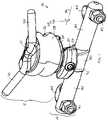
- FIGS. 1 and 2are simplified pictorial illustrations of a spinal prosthesis, seen at front and rear perspective views, constructed and operative in accordance with an embodiment of the present invention.
- FIGS. 3 and 4are simplified pictorial illustrations of the spinal prosthesis of FIGS. 1 and 2 , attached to spinal structure with pedicle screws, respectively in exploded perspective and side views.
- FIGS. 1-4illustrate a spinal prosthesis 10 , constructed and operative in accordance with an embodiment of the present invention.
- the spinal prosthesis 10may include a first spinal prosthetic member 12 , which may be attached to a first spinal structure 14 , such as but not limited to, a vertebra (e.g., L3, as seen in FIG. 4 ).
- the spinal prosthesis 10may also include a second spinal prosthetic member 16 , which may be attached to a second spinal structure 18 , such as but not limited to, a vertebra (e.g., L4, as seen in FIG. 4 ).
- a vertebrae.g., L4
- One non-limiting way of attaching the first and second spinal prosthetic member 12 and 16 to the first and second spinal structures 14 and 18is described more in detail hereinbelow.
- the first and second spinal prosthetic members 12 and 16may be movably attached to one another with a fastening device 20 .
- the fastening device 20has a non-tightened position which permits spatial movement of the first and second spinal prosthetic members 12 and 16 with respect to one another at a desired orientation, and a tightened position which fixes the first and second spinal prosthetic members 12 and 16 at the desired orientation.
- the first spinal prosthetic member 12may include a first (e.g., upper or superior) attachment member 22 and a second (e.g., lower or inferior) attachment member 24 .
- the attachment members 22 and 24may be rigid or non-rigid, formed of materials including, but not limited to, a biocompatible material such as a metal, e.g., stainless steel, titanium or titanium alloy, cobalt chromium alloys, plastics or other hard, rigid materials or any combination of the above.
- a flexure assembly 26may be placed between and may be integrally formed with or attached to the first and second attachment members 22 and 24 .
- a boot 28may be placed at least partially or fully around the first and second attachment members 22 and 24 .
- the boot 28may have any suitable shape or size, such as but not limited to, a ring, a stocking, an ellipsoid and other shapes.
- the flexure assembly 26may be constructed of a compliant, elastomeric material including, but not limited to, polyurethane containing materials, silicone containing materials, polyethylene based elastomers, hydrogels, and polypropylene containing materials.
- Boot 28may also be made of a compliant material, such as but not limited to, an elastomer (e.g., polyurethane) or cloth (woven or non-woven synthetic or natural fibers).
- the flexure assembly 26may permit omnidirectional flexure of the first spinal prosthetic member 12 .
- the first attachment member 22may include at least one attachment point attachable to the first spinal structure 14 , such as but not limited to, a pair of rounded prongs 30 from which depending pedicle screws 32 ( FIGS. 3 and 4 ) that screw into the first spinal structure 14 (e.g., pedicles).
- the pedicle screws 32may comprise, without limitation, polyaxial pedicle screws, e.g., made of titanium or titanium alloy, commercially available in many sizes and shapes from many manufacturers. It is noted that titanium is highly resistant to corrosion and fatigue, and is MRI compatible.
- the pedicle screw 32may have a mobile, swivel head 34 , whose ability to swivel may help avoid vertebral stress.
- the swivel heads 34may be rotatably attached to the rounded prongs 30 by means of lock nuts 36 that mate with heads 34 .
- the second attachment member 24may include a base with an extension 38 that is formed with a non-straight (e.g., convexly curved) interface surface for interfacing and articulating with the second spinal prosthetic member 16 .
- the second attachment member 24may be rigid or non-rigid, formed of materials including, but not limited to, a biocompatible material such as a metal, e.g., stainless steel, titanium or titanium alloy, cobalt chromium alloys, plastics or other hard, rigid materials or any combination of the above.
- the second attachment member 24may be movably attached to the second spinal prosthetic member 16 with the fastening device 20 , as is now described.
- the second spinal prosthetic member 16includes a unitary body with laterally extending arms 40 .
- Mounting hardwareis positioned along the arms 40 , such as but not limited to, a pair of screws 42 which can tighten hooks 44 against fusion rods 46 , which may be attached to the second spinal structure 18 (e.g., pedicles in L4 and L5 in FIGS. 3 and 4 ) with pedicle screws 48 .
- the second spinal prosthetic member 16is formed with a non-straight interface 50 , e.g., a concave surface, which articulates with extension 38 of the second attachment member 24 .
- the fastening device 20includes a threaded fastener 52 and a spacer member 54 .
- the spacer member 54may have a non-straight surface that interfaces with and is tightened by the threaded fastener 52 against the non-straight surfaces of the first and second spinal prosthetic members 12 and 16 .
- the first and second spinal prosthetic members 12 and 16may thus be pivotable with respect to one another about a first pivot axis 56 to define an angle A between the first and second spinal prosthetic members 12 and 16 that corresponds to a lordotic angle between the first and second spinal structures 14 and 18 .
- the first and second spinal prosthetic members 12 and 16may be pivoted in-situ.
- the fastening device 20in its tightened position, fixes the first and second spinal prosthetic members 12 and 16 at a desired orientation along the non-straight surfaces thereof.
- first and second spinal prosthetic members 12 and 16may be further pivotable with respect to one another about a second pivot axis 60 angled at a non-zero angle with respect to the first pivot axis 56 . This may provide further in-situ adjustment capability.
Landscapes
- Health & Medical Sciences (AREA)
- Orthopedic Medicine & Surgery (AREA)
- Neurology (AREA)
- Life Sciences & Earth Sciences (AREA)
- Surgery (AREA)
- Engineering & Computer Science (AREA)
- Biomedical Technology (AREA)
- General Health & Medical Sciences (AREA)
- Veterinary Medicine (AREA)
- Heart & Thoracic Surgery (AREA)
- Public Health (AREA)
- Animal Behavior & Ethology (AREA)
- Molecular Biology (AREA)
- Medical Informatics (AREA)
- Nuclear Medicine, Radiotherapy & Molecular Imaging (AREA)
- Cardiology (AREA)
- Oral & Maxillofacial Surgery (AREA)
- Transplantation (AREA)
- Vascular Medicine (AREA)
- Prostheses (AREA)
- Surgical Instruments (AREA)
Abstract
Description
Claims (3)
Priority Applications (13)
| Application Number | Priority Date | Filing Date | Title |
|---|---|---|---|
| US11/019,276US7491238B2 (en) | 2004-12-23 | 2004-12-23 | Adjustable spinal prosthesis |
| EP05817944AEP1848354B1 (en) | 2004-12-23 | 2005-12-22 | Adjustable spinal prosthesis |
| ZA200705696AZA200705696B (en) | 2004-12-23 | 2005-12-22 | Adjustable spinal prosthesis |
| BRPI0519373ABRPI0519373B8 (en) | 2004-12-23 | 2005-12-22 | adjustable spinal prosthesis |
| PCT/IL2005/001368WO2006067790A1 (en) | 2004-12-23 | 2005-12-22 | Adjustable spinal prosthesis |
| CN2005800446079ACN101087566B (en) | 2004-12-23 | 2005-12-22 | Adjustable spinal prosthesis |
| AU2005317570AAU2005317570A1 (en) | 2004-12-23 | 2005-12-22 | Adjustable spinal prosthesis |
| DE602005022495TDE602005022495D1 (en) | 2004-12-23 | 2005-12-22 | ADJUSTABLE SPINE PROSTHESIS |
| CA002591213ACA2591213A1 (en) | 2004-12-23 | 2005-12-22 | Adjustable spinal prosthesis |
| AT05817944TATE474512T1 (en) | 2004-12-23 | 2005-12-22 | ADJUSTABLE SPINAL PROSTHESIS |
| JP2007547789AJP5089399B2 (en) | 2004-12-23 | 2005-12-22 | Adjustable spinal prosthesis |
| RU2007127779/14ARU2387403C2 (en) | 2004-12-23 | 2005-12-22 | Regulated spinal prosthesis |
| KR1020077015162AKR20070104544A (en) | 2004-12-23 | 2005-12-22 | Adjustable prosthesis of the spine |
Applications Claiming Priority (1)
| Application Number | Priority Date | Filing Date | Title |
|---|---|---|---|
| US11/019,276US7491238B2 (en) | 2004-12-23 | 2004-12-23 | Adjustable spinal prosthesis |
Publications (2)
| Publication Number | Publication Date |
|---|---|
| US20060142759A1 US20060142759A1 (en) | 2006-06-29 |
| US7491238B2true US7491238B2 (en) | 2009-02-17 |
Family
ID=36061425
Family Applications (1)
| Application Number | Title | Priority Date | Filing Date |
|---|---|---|---|
| US11/019,276Active2026-06-05US7491238B2 (en) | 2004-12-23 | 2004-12-23 | Adjustable spinal prosthesis |
Country Status (13)
| Country | Link |
|---|---|
| US (1) | US7491238B2 (en) |
| EP (1) | EP1848354B1 (en) |
| JP (1) | JP5089399B2 (en) |
| KR (1) | KR20070104544A (en) |
| CN (1) | CN101087566B (en) |
| AT (1) | ATE474512T1 (en) |
| AU (1) | AU2005317570A1 (en) |
| BR (1) | BRPI0519373B8 (en) |
| CA (1) | CA2591213A1 (en) |
| DE (1) | DE602005022495D1 (en) |
| RU (1) | RU2387403C2 (en) |
| WO (1) | WO2006067790A1 (en) |
| ZA (1) | ZA200705696B (en) |
Cited By (11)
| Publication number | Priority date | Publication date | Assignee | Title |
|---|---|---|---|---|
| US20060241601A1 (en)* | 2005-04-08 | 2006-10-26 | Trautwein Frank T | Interspinous vertebral and lumbosacral stabilization devices and methods of use |
| US20080140075A1 (en)* | 2006-12-07 | 2008-06-12 | Ensign Michael D | Press-On Pedicle Screw Assembly |
| US20080195213A1 (en)* | 2007-02-12 | 2008-08-14 | Brigham Young University | Spinal implant |
| US20100121381A1 (en)* | 2008-06-09 | 2010-05-13 | Springback, Inc. | Surgical method and apparatus for treating spinal stenosis and stabilization of vertebrae |
| US20100211106A1 (en)* | 2009-02-19 | 2010-08-19 | Bowden Anton E | Compliant Dynamic Spinal Implant And Associated Methods |
| US20100241232A1 (en)* | 2007-02-12 | 2010-09-23 | Peter Halverson | Spinal implant |
| US8894687B2 (en) | 2011-04-25 | 2014-11-25 | Nexus Spine, L.L.C. | Coupling system for surgical construct |
| US9157497B1 (en) | 2009-10-30 | 2015-10-13 | Brigham Young University | Lamina emergent torsional joint and related methods |
| US9232965B2 (en) | 2009-02-23 | 2016-01-12 | Nexus Spine, LLC | Press-on link for surgical screws |
| US9333008B2 (en) | 2010-02-19 | 2016-05-10 | Brigham Young University | Serpentine spinal stability device |
| US20190175229A1 (en)* | 2013-03-15 | 2019-06-13 | Jcdb Llc | Spinal Stabilization System With Adjustable Interlaminar Devices |
Families Citing this family (72)
| Publication number | Priority date | Publication date | Assignee | Title |
|---|---|---|---|---|
| US7753958B2 (en) | 2003-08-05 | 2010-07-13 | Gordon Charles R | Expandable intervertebral implant |
| US7799082B2 (en) | 2003-08-05 | 2010-09-21 | Flexuspine, Inc. | Artificial functional spinal unit system and method for use |
| US7909869B2 (en) | 2003-08-05 | 2011-03-22 | Flexuspine, Inc. | Artificial spinal unit assemblies |
| US7588590B2 (en) | 2003-12-10 | 2009-09-15 | Facet Solutions, Inc | Spinal facet implant with spherical implant apposition surface and bone bed and methods of use |
| US8562649B2 (en) | 2004-02-17 | 2013-10-22 | Gmedelaware 2 Llc | System and method for multiple level facet joint arthroplasty and fusion |
| US8333789B2 (en) | 2007-01-10 | 2012-12-18 | Gmedelaware 2 Llc | Facet joint replacement |
| US7717939B2 (en) | 2004-03-31 | 2010-05-18 | Depuy Spine, Inc. | Rod attachment for head to head cross connector |
| US7645294B2 (en) | 2004-03-31 | 2010-01-12 | Depuy Spine, Inc. | Head-to-head connector spinal fixation system |
| US7507242B2 (en) | 2004-06-02 | 2009-03-24 | Facet Solutions | Surgical measurement and resection framework |
| US7717938B2 (en) | 2004-08-27 | 2010-05-18 | Depuy Spine, Inc. | Dual rod cross connectors and inserter tools |
| US8226690B2 (en)* | 2005-07-22 | 2012-07-24 | The Board Of Trustees Of The Leland Stanford Junior University | Systems and methods for stabilization of bone structures |
| US8162985B2 (en) | 2004-10-20 | 2012-04-24 | The Board Of Trustees Of The Leland Stanford Junior University | Systems and methods for posterior dynamic stabilization of the spine |
| US8267969B2 (en) | 2004-10-20 | 2012-09-18 | Exactech, Inc. | Screw systems and methods for use in stabilization of bone structures |
| US7935134B2 (en)* | 2004-10-20 | 2011-05-03 | Exactech, Inc. | Systems and methods for stabilization of bone structures |
| US8025680B2 (en)* | 2004-10-20 | 2011-09-27 | Exactech, Inc. | Systems and methods for posterior dynamic stabilization of the spine |
| US8523865B2 (en) | 2005-07-22 | 2013-09-03 | Exactech, Inc. | Tissue splitter |
| US7879074B2 (en)* | 2005-09-27 | 2011-02-01 | Depuy Spine, Inc. | Posterior dynamic stabilization systems and methods |
| EP1942817B1 (en) | 2005-09-27 | 2014-05-07 | Paradigm Spine, LLC | Interspinous vertebral stabilization devices |
| US8118869B2 (en) | 2006-03-08 | 2012-02-21 | Flexuspine, Inc. | Dynamic interbody device |
| US8096996B2 (en) | 2007-03-20 | 2012-01-17 | Exactech, Inc. | Rod reducer |
| US8361117B2 (en) | 2006-11-08 | 2013-01-29 | Depuy Spine, Inc. | Spinal cross connectors |
| US20080114401A1 (en)* | 2006-11-10 | 2008-05-15 | Warsaw Orthopedic, Inc. | Posterior Fixation Devices and Methods of Use |
| WO2008070863A2 (en) | 2006-12-07 | 2008-06-12 | Interventional Spine, Inc. | Intervertebral implant |
| US7959677B2 (en) | 2007-01-19 | 2011-06-14 | Flexuspine, Inc. | Artificial functional spinal unit system and method for use |
| US20080281361A1 (en)* | 2007-05-10 | 2008-11-13 | Shannon Marlece Vittur | Posterior stabilization and spinous process systems and methods |
| US8840646B2 (en)* | 2007-05-10 | 2014-09-23 | Warsaw Orthopedic, Inc. | Spinous process implants and methods |
| US8070779B2 (en)* | 2007-06-04 | 2011-12-06 | K2M, Inc. | Percutaneous interspinous process device and method |
| US8900307B2 (en) | 2007-06-26 | 2014-12-02 | DePuy Synthes Products, LLC | Highly lordosed fusion cage |
| US8267965B2 (en) | 2007-10-22 | 2012-09-18 | Flexuspine, Inc. | Spinal stabilization systems with dynamic interbody devices |
| US8182514B2 (en) | 2007-10-22 | 2012-05-22 | Flexuspine, Inc. | Dampener system for a posterior stabilization system with a fixed length elongated member |
| US8162994B2 (en) | 2007-10-22 | 2012-04-24 | Flexuspine, Inc. | Posterior stabilization system with isolated, dual dampener systems |
| US8523912B2 (en) | 2007-10-22 | 2013-09-03 | Flexuspine, Inc. | Posterior stabilization systems with shared, dual dampener systems |
| US8187330B2 (en) | 2007-10-22 | 2012-05-29 | Flexuspine, Inc. | Dampener system for a posterior stabilization system with a variable length elongated member |
| US8157844B2 (en) | 2007-10-22 | 2012-04-17 | Flexuspine, Inc. | Dampener system for a posterior stabilization system with a variable length elongated member |
| EP2237748B1 (en) | 2008-01-17 | 2012-09-05 | Synthes GmbH | An expandable intervertebral implant |
| US8936641B2 (en) | 2008-04-05 | 2015-01-20 | DePuy Synthes Products, LLC | Expandable intervertebral implant |
| US20100087867A1 (en)* | 2008-10-03 | 2010-04-08 | Assaf Klein | Fastener assembly that fastens to pedicle screw |
| US20100087864A1 (en)* | 2008-10-03 | 2010-04-08 | Assaf Klein | Fastener assembly that fastens to polyaxial pedicle screw |
| WO2010065277A1 (en)* | 2008-11-25 | 2010-06-10 | Synthes Usa, Llc | Visco-elastic facet joint implant |
| US9526620B2 (en) | 2009-03-30 | 2016-12-27 | DePuy Synthes Products, Inc. | Zero profile spinal fusion cage |
| US9393129B2 (en) | 2009-12-10 | 2016-07-19 | DePuy Synthes Products, Inc. | Bellows-like expandable interbody fusion cage |
| US8979860B2 (en) | 2010-06-24 | 2015-03-17 | DePuy Synthes Products. LLC | Enhanced cage insertion device |
| US9907560B2 (en) | 2010-06-24 | 2018-03-06 | DePuy Synthes Products, Inc. | Flexible vertebral body shavers |
| US8623091B2 (en) | 2010-06-29 | 2014-01-07 | DePuy Synthes Products, LLC | Distractible intervertebral implant |
| US20120078372A1 (en) | 2010-09-23 | 2012-03-29 | Thomas Gamache | Novel implant inserter having a laterally-extending dovetail engagement feature |
| US9402732B2 (en) | 2010-10-11 | 2016-08-02 | DePuy Synthes Products, Inc. | Expandable interspinous process spacer implant |
| US8388687B2 (en) | 2011-03-25 | 2013-03-05 | Flexuspine, Inc. | Interbody device insertion systems and methods |
| FR2977139B1 (en) | 2011-06-30 | 2014-08-22 | Ldr Medical | INTER-SPINAL IMPLANT AND IMPLANTATION INSTRUMENT |
| US9526627B2 (en) | 2011-11-17 | 2016-12-27 | Exactech, Inc. | Expandable interbody device system and method |
| WO2013177314A1 (en)* | 2012-05-22 | 2013-11-28 | The Regents Of The University Of California | A method and device for restabilization with axial rotation of the atlantoaxial junction |
| US9492288B2 (en) | 2013-02-20 | 2016-11-15 | Flexuspine, Inc. | Expandable fusion device for positioning between adjacent vertebral bodies |
| US9717601B2 (en) | 2013-02-28 | 2017-08-01 | DePuy Synthes Products, Inc. | Expandable intervertebral implant, system, kit and method |
| US9522070B2 (en) | 2013-03-07 | 2016-12-20 | Interventional Spine, Inc. | Intervertebral implant |
| US9510872B2 (en)* | 2013-03-15 | 2016-12-06 | Jcbd, Llc | Spinal stabilization system |
| US9517144B2 (en) | 2014-04-24 | 2016-12-13 | Exactech, Inc. | Limited profile intervertebral implant with incorporated fastening mechanism |
| US10398565B2 (en) | 2014-04-24 | 2019-09-03 | Choice Spine, Llc | Limited profile intervertebral implant with incorporated fastening and locking mechanism |
| US11426290B2 (en) | 2015-03-06 | 2022-08-30 | DePuy Synthes Products, Inc. | Expandable intervertebral implant, system, kit and method |
| US9913727B2 (en)* | 2015-07-02 | 2018-03-13 | Medos International Sarl | Expandable implant |
| CN105708583B (en)* | 2016-01-12 | 2017-06-13 | 南方医科大学 | A kind of artificial Facet Joints system |
| EP3474784A2 (en) | 2016-06-28 | 2019-05-01 | Eit Emerging Implant Technologies GmbH | Expandable and angularly adjustable intervertebral cages with articulating joint |
| US11510788B2 (en) | 2016-06-28 | 2022-11-29 | Eit Emerging Implant Technologies Gmbh | Expandable, angularly adjustable intervertebral cages |
| US10537436B2 (en) | 2016-11-01 | 2020-01-21 | DePuy Synthes Products, Inc. | Curved expandable cage |
| US10888433B2 (en) | 2016-12-14 | 2021-01-12 | DePuy Synthes Products, Inc. | Intervertebral implant inserter and related methods |
| US10398563B2 (en) | 2017-05-08 | 2019-09-03 | Medos International Sarl | Expandable cage |
| US11344424B2 (en) | 2017-06-14 | 2022-05-31 | Medos International Sarl | Expandable intervertebral implant and related methods |
| US10940016B2 (en) | 2017-07-05 | 2021-03-09 | Medos International Sarl | Expandable intervertebral fusion cage |
| US11446156B2 (en) | 2018-10-25 | 2022-09-20 | Medos International Sarl | Expandable intervertebral implant, inserter instrument, and related methods |
| CN109077835B (en)* | 2018-10-26 | 2024-12-10 | 北京爱康宜诚医疗器材有限公司 | Vertebral prosthesis |
| US11426286B2 (en) | 2020-03-06 | 2022-08-30 | Eit Emerging Implant Technologies Gmbh | Expandable intervertebral implant |
| US11850160B2 (en) | 2021-03-26 | 2023-12-26 | Medos International Sarl | Expandable lordotic intervertebral fusion cage |
| US11752009B2 (en) | 2021-04-06 | 2023-09-12 | Medos International Sarl | Expandable intervertebral fusion cage |
| US12090064B2 (en) | 2022-03-01 | 2024-09-17 | Medos International Sarl | Stabilization members for expandable intervertebral implants, and related systems and methods |
Citations (18)
| Publication number | Priority date | Publication date | Assignee | Title |
|---|---|---|---|---|
| US4759769A (en)* | 1987-02-12 | 1988-07-26 | Health & Research Services Inc. | Artificial spinal disc |
| US4932975A (en)* | 1989-10-16 | 1990-06-12 | Vanderbilt University | Vertebral prosthesis |
| US5057109A (en) | 1989-10-16 | 1991-10-15 | Sven Olerud | Fixing instruments for spinal surgery |
| US5683465A (en)* | 1996-03-18 | 1997-11-04 | Shinn; Gary Lee | Artificial intervertebral disk prosthesis |
| US6296644B1 (en) | 1998-08-26 | 2001-10-02 | Jean Saurat | Spinal instrumentation system with articulated modules |
| US6454807B1 (en)* | 2000-11-30 | 2002-09-24 | Roger P. Jackson | Articulated expandable spinal fusion cage system |
| US20020143330A1 (en)* | 2001-04-02 | 2002-10-03 | Endius Incorporated | Polyaxial transverse connector |
| US20040002708A1 (en)* | 2002-05-08 | 2004-01-01 | Stephen Ritland | Dynamic fixation device and method of use |
| US20040116928A1 (en)* | 2002-10-28 | 2004-06-17 | Young J. Stewart | Multi-axial, cross-link connector system for spinal implants |
| US20040153160A1 (en)* | 2002-10-30 | 2004-08-05 | Carrasco Mauricio Rodolfo | Implant for vertebral replacement and restoration of the normal spinal curvature |
| US20050102028A1 (en)* | 2003-11-07 | 2005-05-12 | Uri Arnin | Spinal prostheses |
| US20050119748A1 (en)* | 1999-10-22 | 2005-06-02 | Reiley Mark A. | Prostheses, systems and methods for replacement of natural facet joints with artificial facet joint surfaces |
| US20050228381A1 (en)* | 2004-04-09 | 2005-10-13 | Kirschman David L | Disk augmentation system and method |
| US20050267579A1 (en)* | 1999-10-22 | 2005-12-01 | Reiley Mark A | Implantable device for facet joint replacement |
| US20050277930A1 (en)* | 2004-05-27 | 2005-12-15 | Depuy Spine, Inc. | Tri-joint implant |
| US20060052785A1 (en)* | 2004-08-18 | 2006-03-09 | Augostino Teena M | Adjacent level facet arthroplasty devices, spine stabilization systems, and methods |
| US20060100707A1 (en)* | 2003-07-08 | 2006-05-11 | David Stinson | Prostheses, tools and methods for replacement of natural facet joints with artificial facet joint surfaces |
| US20060129239A1 (en)* | 2004-12-13 | 2006-06-15 | Kwak Seungkyu D | Artificial facet joint device having a compression spring |
Family Cites Families (6)
| Publication number | Priority date | Publication date | Assignee | Title |
|---|---|---|---|---|
| RU2086203C1 (en)* | 1995-07-11 | 1997-08-10 | Научно-исследовательский центр Татарстана "Восстановительная травматология и ортопедия" | Device for functional correction and stabilization of vertebral column |
| RU2103937C1 (en)* | 1995-12-20 | 1998-02-10 | Андрей Владимирович Кедров | Posterior spring-type device for fixing vertebral column |
| FR2751864B1 (en)* | 1996-08-01 | 1999-04-30 | Graf Henry | DEVICE FOR MECHANICALLY CONNECTING AND ASSISTING VERTEBRES BETWEEN THEM |
| CA2373719A1 (en)* | 1999-05-14 | 2000-11-23 | Synthes (U.S.A.) | Bone fixation device with a rotation joint |
| RU2197915C1 (en)* | 2001-06-14 | 2003-02-10 | Общество с ограниченной ответственностью Научно-производственное объединение "Остеомед" | Device for fixing vertebral column |
| FR2835173B1 (en)* | 2002-01-28 | 2004-11-05 | Biomet Merck France | INTERTEPINEOUS VERTEBRAL IMPLANT |
- 2004
- 2004-12-23USUS11/019,276patent/US7491238B2/enactiveActive
- 2005
- 2005-12-22WOPCT/IL2005/001368patent/WO2006067790A1/enactiveApplication Filing
- 2005-12-22JPJP2007547789Apatent/JP5089399B2/enactiveActive
- 2005-12-22CNCN2005800446079Apatent/CN101087566B/enactiveActive
- 2005-12-22ATAT05817944Tpatent/ATE474512T1/ennot_activeIP Right Cessation
- 2005-12-22CACA002591213Apatent/CA2591213A1/ennot_activeAbandoned
- 2005-12-22ZAZA200705696Apatent/ZA200705696B/enunknown
- 2005-12-22DEDE602005022495Tpatent/DE602005022495D1/enactiveActive
- 2005-12-22KRKR1020077015162Apatent/KR20070104544A/ennot_activeWithdrawn
- 2005-12-22RURU2007127779/14Apatent/RU2387403C2/ennot_activeIP Right Cessation
- 2005-12-22EPEP05817944Apatent/EP1848354B1/ennot_activeNot-in-force
- 2005-12-22AUAU2005317570Apatent/AU2005317570A1/ennot_activeAbandoned
- 2005-12-22BRBRPI0519373Apatent/BRPI0519373B8/enactiveIP Right Grant
Patent Citations (18)
| Publication number | Priority date | Publication date | Assignee | Title |
|---|---|---|---|---|
| US4759769A (en)* | 1987-02-12 | 1988-07-26 | Health & Research Services Inc. | Artificial spinal disc |
| US4932975A (en)* | 1989-10-16 | 1990-06-12 | Vanderbilt University | Vertebral prosthesis |
| US5057109A (en) | 1989-10-16 | 1991-10-15 | Sven Olerud | Fixing instruments for spinal surgery |
| US5683465A (en)* | 1996-03-18 | 1997-11-04 | Shinn; Gary Lee | Artificial intervertebral disk prosthesis |
| US6296644B1 (en) | 1998-08-26 | 2001-10-02 | Jean Saurat | Spinal instrumentation system with articulated modules |
| US20050119748A1 (en)* | 1999-10-22 | 2005-06-02 | Reiley Mark A. | Prostheses, systems and methods for replacement of natural facet joints with artificial facet joint surfaces |
| US20050267579A1 (en)* | 1999-10-22 | 2005-12-01 | Reiley Mark A | Implantable device for facet joint replacement |
| US6454807B1 (en)* | 2000-11-30 | 2002-09-24 | Roger P. Jackson | Articulated expandable spinal fusion cage system |
| US20020143330A1 (en)* | 2001-04-02 | 2002-10-03 | Endius Incorporated | Polyaxial transverse connector |
| US20040002708A1 (en)* | 2002-05-08 | 2004-01-01 | Stephen Ritland | Dynamic fixation device and method of use |
| US20040116928A1 (en)* | 2002-10-28 | 2004-06-17 | Young J. Stewart | Multi-axial, cross-link connector system for spinal implants |
| US20040153160A1 (en)* | 2002-10-30 | 2004-08-05 | Carrasco Mauricio Rodolfo | Implant for vertebral replacement and restoration of the normal spinal curvature |
| US20060100707A1 (en)* | 2003-07-08 | 2006-05-11 | David Stinson | Prostheses, tools and methods for replacement of natural facet joints with artificial facet joint surfaces |
| US20050102028A1 (en)* | 2003-11-07 | 2005-05-12 | Uri Arnin | Spinal prostheses |
| US20050228381A1 (en)* | 2004-04-09 | 2005-10-13 | Kirschman David L | Disk augmentation system and method |
| US20050277930A1 (en)* | 2004-05-27 | 2005-12-15 | Depuy Spine, Inc. | Tri-joint implant |
| US20060052785A1 (en)* | 2004-08-18 | 2006-03-09 | Augostino Teena M | Adjacent level facet arthroplasty devices, spine stabilization systems, and methods |
| US20060129239A1 (en)* | 2004-12-13 | 2006-06-15 | Kwak Seungkyu D | Artificial facet joint device having a compression spring |
Cited By (25)
| Publication number | Priority date | Publication date | Assignee | Title |
|---|---|---|---|---|
| US8470000B2 (en)* | 2005-04-08 | 2013-06-25 | Paradigm Spine, Llc | Interspinous vertebral and lumbosacral stabilization devices and methods of use |
| US10194956B2 (en) | 2005-04-08 | 2019-02-05 | Paradigm Spine, Llc | Interspinous vertebral and lumbosacral stabilization devices and methods of use |
| US20060241601A1 (en)* | 2005-04-08 | 2006-10-26 | Trautwein Frank T | Interspinous vertebral and lumbosacral stabilization devices and methods of use |
| US9402657B2 (en) | 2005-04-08 | 2016-08-02 | Paradigm Spine, Llc | Interspinous vertebral and lumbosacral stabilization devices and methods of use |
| US20080140075A1 (en)* | 2006-12-07 | 2008-06-12 | Ensign Michael D | Press-On Pedicle Screw Assembly |
| US12364511B2 (en) | 2006-12-07 | 2025-07-22 | Nexus Spine, LLC | Press-on pedicle screw assembly |
| US9867640B2 (en) | 2006-12-07 | 2018-01-16 | Nexus Spine, LLC | Press-on pedicle screw assembly |
| US20080195213A1 (en)* | 2007-02-12 | 2008-08-14 | Brigham Young University | Spinal implant |
| US20100241232A1 (en)* | 2007-02-12 | 2010-09-23 | Peter Halverson | Spinal implant |
| US9314346B2 (en) | 2007-02-12 | 2016-04-19 | Brigham Young University | Spinal implant |
| US8308801B2 (en) | 2007-02-12 | 2012-11-13 | Brigham Young University | Spinal implant |
| US20100121381A1 (en)* | 2008-06-09 | 2010-05-13 | Springback, Inc. | Surgical method and apparatus for treating spinal stenosis and stabilization of vertebrae |
| US20100217326A1 (en)* | 2009-02-19 | 2010-08-26 | Bowden Anton E | Method of Treating A Degenerate Spinal Segment |
| US8663286B2 (en) | 2009-02-19 | 2014-03-04 | Brigham Young University | Compliant dynamic spinal implant and associated methods |
| US8172883B2 (en) | 2009-02-19 | 2012-05-08 | Brigham Young University | Method of treating a degenerate spinal segment |
| US20100222823A1 (en)* | 2009-02-19 | 2010-09-02 | Bowden Anton E | Method Of Surgically Implanting A Spinal Implant |
| US20100222821A1 (en)* | 2009-02-19 | 2010-09-02 | Bowden Anton E | Compliant Dynamic Spinal Implant |
| US20100217324A1 (en)* | 2009-02-19 | 2010-08-26 | Bowden Anton E | Compliant Dynamic Spinal Implant And Associated Methods |
| US20100211106A1 (en)* | 2009-02-19 | 2010-08-19 | Bowden Anton E | Compliant Dynamic Spinal Implant And Associated Methods |
| US9232965B2 (en) | 2009-02-23 | 2016-01-12 | Nexus Spine, LLC | Press-on link for surgical screws |
| US9157497B1 (en) | 2009-10-30 | 2015-10-13 | Brigham Young University | Lamina emergent torsional joint and related methods |
| US9333008B2 (en) | 2010-02-19 | 2016-05-10 | Brigham Young University | Serpentine spinal stability device |
| US8894687B2 (en) | 2011-04-25 | 2014-11-25 | Nexus Spine, L.L.C. | Coupling system for surgical construct |
| US20190175229A1 (en)* | 2013-03-15 | 2019-06-13 | Jcdb Llc | Spinal Stabilization System With Adjustable Interlaminar Devices |
| US11213325B2 (en)* | 2013-03-15 | 2022-01-04 | Jcbd, Llc | Spinal stabilization system with adjustable interlaminar devices |
Also Published As
| Publication number | Publication date |
|---|---|
| JP2008535526A (en) | 2008-09-04 |
| JP5089399B2 (en) | 2012-12-05 |
| CN101087566B (en) | 2010-06-16 |
| ATE474512T1 (en) | 2010-08-15 |
| AU2005317570A1 (en) | 2006-06-29 |
| RU2387403C2 (en) | 2010-04-27 |
| CA2591213A1 (en) | 2006-06-29 |
| WO2006067790A1 (en) | 2006-06-29 |
| RU2007127779A (en) | 2009-01-27 |
| EP1848354B1 (en) | 2010-07-21 |
| EP1848354A1 (en) | 2007-10-31 |
| ZA200705696B (en) | 2009-03-25 |
| BRPI0519373A2 (en) | 2009-01-20 |
| KR20070104544A (en) | 2007-10-26 |
| BRPI0519373B1 (en) | 2018-01-23 |
| US20060142759A1 (en) | 2006-06-29 |
| CN101087566A (en) | 2007-12-12 |
| BRPI0519373B8 (en) | 2021-06-22 |
| DE602005022495D1 (en) | 2010-09-02 |
Similar Documents
| Publication | Publication Date | Title |
|---|---|---|
| US7491238B2 (en) | Adjustable spinal prosthesis | |
| EP1933737B1 (en) | Adjustable spinal prostheses | |
| EP1945116B1 (en) | Spinal prosthesis | |
| US7833272B2 (en) | Spinal prostheses | |
| KR20070029645A (en) | Multi-Axis Adjustable Post-Joint Prosthesis | |
| US20150018950A1 (en) | Flexure limiter for spinal prosthesis | |
| EP3634279A1 (en) | Multi-level vertebral implant system |
Legal Events
| Date | Code | Title | Description |
|---|---|---|---|
| AS | Assignment | Owner name:IMPLIANT LTD., ISRAEL Free format text:ASSIGNMENT OF ASSIGNORS INTEREST;ASSIGNORS:ARNIN, URI;SUDIN, YURI;FLEISCHER, SHAI;REEL/FRAME:019563/0655 Effective date:20041221 | |
| STCF | Information on status: patent grant | Free format text:PATENTED CASE | |
| AS | Assignment | Owner name:PREMIA SPINE LTD., ISRAEL Free format text:ASSIGNMENT OF ASSIGNORS INTEREST;ASSIGNOR:IMPLIANT LTD.;REEL/FRAME:026761/0863 Effective date:20110531 | |
| FPAY | Fee payment | Year of fee payment:4 | |
| REMI | Maintenance fee reminder mailed | ||
| FPAY | Fee payment | Year of fee payment:8 | |
| SULP | Surcharge for late payment | Year of fee payment:7 | |
| FEPP | Fee payment procedure | Free format text:MAINTENANCE FEE REMINDER MAILED (ORIGINAL EVENT CODE: REM.); ENTITY STATUS OF PATENT OWNER: SMALL ENTITY | |
| FEPP | Fee payment procedure | Free format text:11.5 YR SURCHARGE- LATE PMT W/IN 6 MO, SMALL ENTITY (ORIGINAL EVENT CODE: M2556); ENTITY STATUS OF PATENT OWNER: SMALL ENTITY | |
| MAFP | Maintenance fee payment | Free format text:PAYMENT OF MAINTENANCE FEE, 12TH YR, SMALL ENTITY (ORIGINAL EVENT CODE: M2553); ENTITY STATUS OF PATENT OWNER: SMALL ENTITY Year of fee payment:12 | |
| AS | Assignment | Owner name:JPMORGAN CHASE BANK, N.A., NEW YORK Free format text:SECURITY INTEREST;ASSIGNORS:PREMIA SPINE INCORPORATED;PREMIA SPINE LTD;REEL/FRAME:072310/0703 Effective date:20250918 |