US7491208B2 - Instrument and method for guiding surgical implants and instruments during surgery - Google Patents
Instrument and method for guiding surgical implants and instruments during surgeryDownload PDFInfo
- Publication number
- US7491208B2 US7491208B2US11/117,034US11703405AUS7491208B2US 7491208 B2US7491208 B2US 7491208B2US 11703405 AUS11703405 AUS 11703405AUS 7491208 B2US7491208 B2US 7491208B2
- Authority
- US
- United States
- Prior art keywords
- bone anchor
- medial surface
- extender
- extending
- clip
- Prior art date
- Legal status (The legal status is an assumption and is not a legal conclusion. Google has not performed a legal analysis and makes no representation as to the accuracy of the status listed.)
- Active, expires
Links
Images


Classifications
- A—HUMAN NECESSITIES
- A61—MEDICAL OR VETERINARY SCIENCE; HYGIENE
- A61B—DIAGNOSIS; SURGERY; IDENTIFICATION
- A61B17/00—Surgical instruments, devices or methods
- A61B17/56—Surgical instruments or methods for treatment of bones or joints; Devices specially adapted therefor
- A61B17/58—Surgical instruments or methods for treatment of bones or joints; Devices specially adapted therefor for osteosynthesis, e.g. bone plates, screws or setting implements
- A61B17/68—Internal fixation devices, including fasteners and spinal fixators, even if a part thereof projects from the skin
- A61B17/70—Spinal positioners or stabilisers, e.g. stabilisers comprising fluid filler in an implant
- A61B17/7074—Tools specially adapted for spinal fixation operations other than for bone removal or filler handling
- A61B17/7076—Tools specially adapted for spinal fixation operations other than for bone removal or filler handling for driving, positioning or assembling spinal clamps or bone anchors specially adapted for spinal fixation
- A61B17/7082—Tools specially adapted for spinal fixation operations other than for bone removal or filler handling for driving, positioning or assembling spinal clamps or bone anchors specially adapted for spinal fixation for driving, i.e. rotating, screws or screw parts specially adapted for spinal fixation, e.g. for driving polyaxial or tulip-headed screws
- A—HUMAN NECESSITIES
- A61—MEDICAL OR VETERINARY SCIENCE; HYGIENE
- A61B—DIAGNOSIS; SURGERY; IDENTIFICATION
- A61B17/00—Surgical instruments, devices or methods
- A61B17/56—Surgical instruments or methods for treatment of bones or joints; Devices specially adapted therefor
- A61B17/58—Surgical instruments or methods for treatment of bones or joints; Devices specially adapted therefor for osteosynthesis, e.g. bone plates, screws or setting implements
- A61B17/68—Internal fixation devices, including fasteners and spinal fixators, even if a part thereof projects from the skin
- A61B17/70—Spinal positioners or stabilisers, e.g. stabilisers comprising fluid filler in an implant
- A61B17/7074—Tools specially adapted for spinal fixation operations other than for bone removal or filler handling
- A61B17/7083—Tools for guidance or insertion of tethers, rod-to-anchor connectors, rod-to-rod connectors, or longitudinal elements
- A61B17/7085—Tools for guidance or insertion of tethers, rod-to-anchor connectors, rod-to-rod connectors, or longitudinal elements for insertion of a longitudinal element down one or more hollow screw or hook extensions, i.e. at least a part of the element within an extension has a component of movement parallel to the extension's axis
- A—HUMAN NECESSITIES
- A61—MEDICAL OR VETERINARY SCIENCE; HYGIENE
- A61B—DIAGNOSIS; SURGERY; IDENTIFICATION
- A61B17/00—Surgical instruments, devices or methods
- A61B17/56—Surgical instruments or methods for treatment of bones or joints; Devices specially adapted therefor
- A61B17/58—Surgical instruments or methods for treatment of bones or joints; Devices specially adapted therefor for osteosynthesis, e.g. bone plates, screws or setting implements
- A61B17/68—Internal fixation devices, including fasteners and spinal fixators, even if a part thereof projects from the skin
- A61B17/70—Spinal positioners or stabilisers, e.g. stabilisers comprising fluid filler in an implant
- A61B17/7074—Tools specially adapted for spinal fixation operations other than for bone removal or filler handling
- A61B17/7091—Tools specially adapted for spinal fixation operations other than for bone removal or filler handling for applying, tightening or removing longitudinal element-to-bone anchor locking elements, e.g. caps, set screws, nuts or wedges
- A—HUMAN NECESSITIES
- A61—MEDICAL OR VETERINARY SCIENCE; HYGIENE
- A61B—DIAGNOSIS; SURGERY; IDENTIFICATION
- A61B17/00—Surgical instruments, devices or methods
- A61B17/56—Surgical instruments or methods for treatment of bones or joints; Devices specially adapted therefor
- A61B17/58—Surgical instruments or methods for treatment of bones or joints; Devices specially adapted therefor for osteosynthesis, e.g. bone plates, screws or setting implements
- A61B17/68—Internal fixation devices, including fasteners and spinal fixators, even if a part thereof projects from the skin
- A61B17/70—Spinal positioners or stabilisers, e.g. stabilisers comprising fluid filler in an implant
- A61B17/7001—Screws or hooks combined with longitudinal elements which do not contact vertebrae
- A61B17/7002—Longitudinal elements, e.g. rods
- A61B17/7011—Longitudinal element being non-straight, e.g. curved, angled or branched
- A—HUMAN NECESSITIES
- A61—MEDICAL OR VETERINARY SCIENCE; HYGIENE
- A61B—DIAGNOSIS; SURGERY; IDENTIFICATION
- A61B17/00—Surgical instruments, devices or methods
- A61B17/56—Surgical instruments or methods for treatment of bones or joints; Devices specially adapted therefor
- A61B17/58—Surgical instruments or methods for treatment of bones or joints; Devices specially adapted therefor for osteosynthesis, e.g. bone plates, screws or setting implements
- A61B17/68—Internal fixation devices, including fasteners and spinal fixators, even if a part thereof projects from the skin
- A61B17/70—Spinal positioners or stabilisers, e.g. stabilisers comprising fluid filler in an implant
- A61B17/7001—Screws or hooks combined with longitudinal elements which do not contact vertebrae
- A61B17/7032—Screws or hooks with U-shaped head or back through which longitudinal rods pass
Definitions
- the present inventionrelates to surgical devices and methods and more particularly, but not exclusively, to fixation element extension devices for use during surgical procedures.
- fixation elementsthat can be secured to bone or bony structures. These fixation elements can be used to apply stabilizing or corrective forces to the bone or bony structures.
- fixation elementscan include bone screws, posts or spikes that can be anchored into various bones or bony structures.
- another fixation elementis a hook that is configured to engage the laminae of the vertebra.
- fixation elementsinclude spinal screws or bolts having threaded sections that are configured to be anchored in vertebral bone. With reference to spinal surgery, the spinal screws are typically used in conjunction with other implant components used to stabilize the vertebra.
- implant componentscan include, for example, a stabilization device, such as, a spinal rod or plate.
- spinal screwsinclude a connector portion that is adapted to engage the stabilization device.
- the connector portionusually has a first opening adapted to receive and engage an upper portion of the spinal screw, and a second opening adapted to receive and engage the stabilization device.
- the second openingis also configured to engage a securing member that connects the stabilization device to the spinal screw.
- Assembly, delivery and manipulation of the implant components described hereinabovecan be awkward or cumbersome due to the limited amount of space available to manipulate the implant components and the required surgical instruments. Additionally, if the second opening of the connector portion is not properly aligned, difficulty can be encountered inserting various implant components to the surgical site. Further, if the openings in the connector portions are not aligned with the stabilization devices, forces may need to be applied to stress the stabilization devices to achieve proper alignment with the connector portions. Also, the assembly and manipulation of multiple implant components within the surgical site can be tedious and time consuming, thus, prolonging the surgical procedure and increasing the risks associated therewith. In addition, there are risks associated with mishandling the implant components during delivery to the surgical site, and, if guiding devices are not used, the implant components can be dropped or improperly located within the surgical site.
- a devicefor guiding surgical implants to a bone anchor during surgery.
- the deviceincludes a first bone anchor extender releasably attachable to a first portion of a head portion of the bone anchor.
- the first bone anchor extenderincludes a first clip for receiving and releasably attaching to the first portion of the head portion of the bone anchor, and a first extension portion extending longitudinally from the first clip to a position above said head portion of the bone anchor when the first clip is releasably attached to the head portion of the bone anchor.
- a second bone anchor extenderis provided and is releasably attachable to a second portion of the head portion of the bone anchor.
- the second bone anchor extenderincludes a second clip for receiving and releasably attaching to the second portion of the head portion of the bone anchor, and a second extension portion extending longitudinally from the second clip to a position above the head portion of the bone anchor when the second clip is releasably attached to the head portion of the bone anchor.
- the first and second bone anchor extendersare used to assist in guiding the surgical implant to the bone anchor.
- a devicefor removing a releasable bone anchor extender from a bone anchor.
- the deviceincludes a handle, a shaft connected to the handle and a head connected to the shaft.
- the headincludes a wedge portion that is adapted to be placed between the bone anchor extender and the bone anchor for releasing the bone anchor extender from the bone anchor when a force is applied to the handle.
- a systemfor securing a bone anchor into a boney elements.
- the systemincludes a bone anchor inserter having a driver that mates with a head of a bone anchor.
- the driveris adapted to secure the bone anchor into the boney element.
- the bone anchor inserterfurther includes an outer surface having a retainer.
- a bone anchor extendercan be releasably attached to the bone anchor.
- the bone anchor extenderhas an elongated portion wherein when the elongated portion is inserted in the retainer of the bone anchor inserter the bone anchor is held in a position for securing the bone anchor into the boney element.
- a systemfor securing a bone anchor to a boney element and guiding an implant to the bone anchor.
- the systemincludes a bone anchor extender releasably attachable to a portion of a head of the bone anchor.
- the bone anchor extenderincludes a clip for receiving and releasably attaching to the portion of the head of the bone anchor and an extension portion extending longitudinally from the clip to a position above the head of the bone anchor when the clip is releasably attached to the head of the bone anchor.
- a bone anchor inserteris provided and includes a driver that mates with a portion of said bone anchor. The driver is adapted to secure the bone anchor into the boney element.
- the bone anchor inserterfurther includes an outer surface having a retainer.
- a bone anchor extender removeris provided that includes a handle connected to a shaft.
- a headis also connected to the shaft, and the head includes a wedge portion adapted to be placed between the bone anchor extender and the bone anchor for releasing the bone anchor extender from the bone anchor when a force is applied to the handle.
- a method for guiding an implant to a bone anchorincludes accessing a vertebral body of the spinal column and implanting a bone anchor in the vertebral body.
- First and second bone anchor extenderare releasably attached to a head portion of the bone anchor.
- Each of the bone anchor extenderscomprise an elongated portion extending above the bone anchor.
- the elongated membersdefine a pathway for the implant.
- the implantis guided along the pathway to the bone anchor.
- the implantis secured within the head portion of the bone anchor.
- the bone anchor extendersare removed from said head portion of said bone anchor.
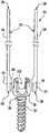
- FIG. 1is a perspective view of one embodiment of extenders and a bone anchor
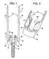
- FIG. 2is a perspective view of one embodiment of extenders attached to a head of a bone anchor
- FIG. 3is a perspective view of one embodiment of a clip of an extender
- FIG. 4is a perspective view on another embodiment of a clip of an extender
- FIG. 5is a front, top and cross-sectional views of one embodiment of an extender
- FIG. 6is a front, top and cross-sectional view of another embodiment of an extender
- FIG. 7is a perspective view of one embodiment of a driver, extenders and bone anchor
- FIG. 8is a perspective of one embodiment of a driver engaged with extenders and a bone anchor
- FIG. 9is a close-up perspective view of one embodiment of a driver engaged with extenders and a bone anchor
- FIG. 10is a perspective view of one embodiment of a driver
- FIG. 11is a front and side view of one embodiment of an extender remover tool
- FIG. 12is a front and side view of one embodiment of a head of an extender remover tool
- FIG. 13is a perspective view of another embodiment of an extender remover tool, extender and a bone anchor;
- FIG. 14is a perspective view of another embodiment of an extender remover tool
- FIG. 15is a perspective view of one embodiment of extenders used in a surgical procedure
- FIG. 16is perspective view of one embodiment of extenders and a bone anchor used in a surgical procedure
- FIG. 17is a perspective view of one embodiment of extenders and an implant used in a surgical procedure
- FIG. 18is a perspective view of one embodiment of extenders, implant and bone anchor used in a surgical procedure.
- FIG. 19is a perspective view of one embodiment of a plurality of extenders used in a surgical procedure.
- one embodiment of the surgical system 10includes extenders 20 that can be releasably attached to a bone anchor 30 .
- the mechanism for releasably attaching the extenders 20 to the bone anchor 30includes clipping the extenders 20 to the bone anchor 30 .
- Each of the extenders 20includes a clip 22 located at a proximal end 26 of the extender 20 . It should be appreciated that the invention encompasses any mechanism that can releasably attach the extenders 20 to the bone anchor 30 .
- each of the extenders 20includes an elongated portion 24 that longitudinally extends from the clip 22 to a distal end 28 of the extender 20 . As further shown in FIG.
- the bone anchor 30comprises a head 32 and a threaded portion 34 .
- the bone anchor 30can comprise, for example, a screw, a multi-axial screw, a staple or a spike.
- the extenders 20are releasably attached to the head 32 of the bone anchor 30 .
- the clip 22 of each of the extenders 20is releasably attached to a portion of the head 32 of the bone anchor 30 .
- the proximal end 26 of the extender 20is positioned near the portion of the head 32 and a force from a user's hand or an appropriate tool is applied to the clip 22 to snap the clip onto the portion of the head 32 .
- the extenders 20are shown in FIG. 1 to comprise two separate extenders 20 , the extenders 20 could be connected as a single unit at any portion along the extender 20 .
- one extender 20can be clipped or attached to the bone anchor 30 .
- the single extender 20can be used to guide an implant 110 ( FIG. 13 ) to the bone anchor 30 .
- the clip 22 of the extender 20includes a medial portion 40 having a first end 42 and a second end 44 .
- Side portions 46extend from the medial portion 40 at both the first end 42 and the second end 44 .
- the side portions 46extend perpendicularly or at a ninety (90) degree angle from the medial portion 40 .
- the side portions 46extend substantially perpendicularly from the medial portion 40 .
- Each side portion 46includes a raised tab 48 .
- Each raised tab 48is positioned a predetermined distance from each of the first interface 52 and the second interface 54 between the medial portion 40 and each of the side portions 46 .
- each of raised tabs 48is located less than 2 millimeters (mm) from the respective first interface 52 or the second interface 54 . In another embodiment, the raised tabs 48 are about 1.35 mm in length.
- one embodiment of the extender 20includes a bumper 50 positioned on the medial portion 40 . In this embodiment, the bumper 50 may be used to ensure proper spacing between the head 32 of the bone anchor 30 and the extender 20 when the extender 20 is attached to the bone anchor 30 .
- the extender 20is shown comprising clip 22 and elongated portion 24 .
- the extender 20includes raised tab portions 48 on side portions 46 .
- the medial portion 40is contoured.
- the contour of the medial portion 40comprises an arc.
- the contour of the medial portion 40is contoured to correspondingly mate with a portion of the head 32 of the bone anchor 30 .
- the elongated portion 24can be substantially flat.
- the raised tab 48includes a retention edge 56 and an angled face 58 .
- the retention edge 56is positioned opposite from the angled face 58 , and the retention edge 56 is positioned closer to the medial portion 40 than the angled face 58 .
- the angled face 58 and the retention edge 56assist in releasably attaching the extender 20 to the bone anchor 30 .
- a portion of the head 32 of the bone anchor 30is placed in contact with the clip 22 of the extender 20 .
- the angled face 58contacts the portion of the head 32 of the bone anchor 30 as a force is applied to the clip 22 of the extender 20 to releasably attach the extender 20 the bone anchor 30 .
- the angled face 58assists in guiding the extender 20 onto the head 32 of the bone anchor 30 .
- the portion of the head 32 of the bone anchor 30is moved along the angled face 58 until it is positioned and captured in the retention edge 56 .
- the extender 20 including its various portions, such as, the elongated portion, 24 , clip 22 , medial portion 40 and side portion 46comprises a thickness that allows the portions of the extender 20 to elastically deform and/or bend and then revert back to their original shape.
- the clip 22 of the extender 20is releasably attached to the bone anchor 30 tightly enough to allow the elongated portion 24 to be elastically deformed or bent without the clip 22 releasing from bone anchor 20 .
- the extender 20has a thickness of 1 to 10 millimeters (mm). In another embodiment, the extender 20 has a thickness of 1 to 5 mm. In even another embodiments, the extender 20 has a thickness of 1, 2, 3, 4, 5, 6, 7, 8, 9 or 10 mm. In yet another embodiment, the extender 20 has a thickness of less than 1 mm. In another embodiment, the extender 20 has a thickness of greater than 10 mm.
- the clip 22is about 11 mm in length and the length of the entire extender 20 is about 154 mm and the width of the elongated portion 24 is about 5 mm.
- the extender 20can be formed from a single piece of material.
- the raised tab 48 and the bumpercan be integrally formed with the clip 22 .
- the extender 20can be composed of a bio-compatible material.
- the extender 20can be composed of a material, such as, titanium, stainless steel or a steel alloy.
- the extender 20can be composed of a polymeric material.
- the extender 20can comprise a clip 22 that is composed of a polymeric material and an elongated portion 24 that is composed of a metallic material.
- the extender 20can comprise a clip 22 that is composed of a metallic material and an elongated portion 24 that is composed of a polymeric material.
- the raised tab 48 having the retention edge 56 and the angled face 58is shown with an extender 20 having a bumper 50 .
- the raised tab 48 having the retention edge 56 and the angled face 58can be used with an extender 20 that does not incorporate a bumper 50 .
- a driver 60includes at least one retainer 62 , a bit 66 and an end 64 .
- the driver 60is used to insert the bone anchor 30 into a boney element of a patient.
- the driver 60comprises an internal mechanism or connection (not shown) to facilitate driving the bone anchor 30 into the boney element.
- the driver 60comprises a bit 66 that mates with a portion of the bone anchor 30 to drive the bone anchor into a boney element.
- the portion of the bone anchor 30 that the bit 66 of the driver 60 mates withis a set screw 96 ( FIG. 13 ). It should be appreciated that, in one embodiment, the set screw 96 ( FIG.
- the set screw 96( FIG. 13 ) is positionable in the center portion 100 ( FIG. 2 ) of the head 32 of the bone anchor 30 , and the set screw 96 ( FIG. 13 ) is used to capture an implant 110 ( FIG. 13 ) in the head 32 of the bone anchor 30 .
- the set screw 96( FIG. 13 ) is threadingly engageable with the head 32 of the bone anchor 30 .
- the bit 66 of the driver 60engages the portion of the bone anchor 30 and rotates the bone anchor 30 to screw the bone anchor 30 in the boney element.
- an internal mechanism(not shown) is used to connect the end 64 to the bit 66 such that movement of the end 64 also moves the bit 66 .
- an external driving deviceconnects to the end 64 to provide an externally powered force to move the end 64 and in turn move the bit 66 to drive the bone anchor 30 into the boney element.
- the externally powered driving devicecan comprise a power drill.
- the movement providedis a rotational force.
- a handle(not shown) could be attached to the end 64 to allow a user to move the end 64 and thereby move the bit 66 of the driver 60 to drive the bone anchor 30 into a boney element.
- the movement of the handlecould comprise a rotational or rotary force.
- the driver 60can use mechanisms other than rotation to drive the bone anchor 30 into the boney element, such as, vertebral body 220 ( FIGS. 16 , 18 and 19 ).
- the extenders 20can assist in holding or mounting the bone anchor 30 to the driver 60 .
- the driver 60includes at least one retainer 62 .
- the retainer 62comprises at least one slot 68 that is adapted to receive the elongated portion 24 of the extender 20 .
- the driver 60includes two retainers 62 and each retainer 62 includes two separate slots 68 for holding the elongated portions 24 of the extenders 20 .
- the driver 60slides down the extenders 20 via the slots 68 of the retainers 62 such that the bit 66 is placed in contact with the portion of the head 32 wherein the bone anchor 30 could be driven into the bone element.
- the driver 60can be removed from the extenders 20 without having to remove the extenders 20 from the bone anchor 30 . It should be appreciated that the bone anchor 30 could be attached to the extenders 20 before or after the elongated portions 24 of the extenders 20 have been inserted into the slots 68 of the retainers 62 on the driver 60 .
- the retainer 62can be securely connected to the driver 60 in a fixed orientation or the retainer 62 can be slidably connected to the driver such that the retainer 62 can slidably move along the length of the driver 60 .
- the ability to have the extenders 20 hold or mount the bone anchor 30 with the driver 60allows the extenders 20 to be in an advantageous position after the bone anchor 30 has been driven into the boney element such that the extenders 20 can be used to guide an implant to the surgical site after the driver 60 is removed from the extenders 20 .
- a removal tool 70includes a shaft 74 that is connected to a handle 72 and a wedge 76 .
- the handle 72is connected to a first end of the shaft 74 and the wedge is connected to a second end of the shaft 74 wherein the first and second end are opposite from one another.
- the removal tool 70shown in FIG. 11 , can comprise a handle 72 , shaft 74 and wedge 76 that are individual pieces that can be assembled together to form the removal tool 70 .
- the removal tool 70includes a handle 72 , shaft 74 and wedge 76 that are integrally formed from single piece that comprises the removal tool 70 .
- the wedge 76includes a slot 84 that accepts the elongated portion 24 of the extender 20 .
- the removal tool 70can be used to release the extender 20 from the bone anchor 30 .
- the removal tool 70is positioned such that the elongated portion 24 is inserted into the slot 84 of the wedge 76 , and the removal tool 70 is slid down the elongated portion 24 of the extender 20 .
- the removal tool 70is moved such that the wedge 76 is located at an interface 78 ( FIG. 2 ) where the extender 20 and the bone anchor 30 meet.
- a forceis applied to handle 72 .
- the wedge 76is pushed between the extender 20 and the bone anchor 30 whereby causing the side portions 46 of the clip 22 to release the clip 22 from the bone anchor 30 .
- the extender 20can be removed from the surgical site.
- the slot 84is sized to allow the thickness of the elongated portion 24 to pass through, but the thickness of the clip 22 is too large to pass through the slot 84 .
- the extender 20is easily retained in the removal tool 70 and can be easily removed from the surgical site together with the removal tool 70 .
- the wedge 78is advantageously shaped to conveniently remove the extender 20 from the bone anchor 30 .
- the wedge 76includes a spike 80 , shoulder 82 and a slot 84 .
- the slot 84accepts the elongated portion 24 of the extender 20 to facilitate locating the wedge 76 to the interface 84 ( FIG. 2 ) and for removal of the extender 20 after the extender 20 is released from the bone anchor 30 .
- the wedge 76also includes a spike 80 that is tapered on its sides. As shown in FIG. 12 , the thickness of the spike 80 increases from end 86 to shoulder 82 . The end 86 of the spike 80 is adapted to fit into the interface 78 ( FIG. 2 ) between the extender 20 and the bone anchor 30 .
- the thickness of the spike 80increases from the end 86 to the shoulder 82 such that as the spike 80 is inserted between the extender 20 and the bone anchor 30 a force is supplied to remove the clip 22 of the extender 20 from the bone anchor 30 .
- the removal tool 70can be moved or rocked to facilitate removal of the extender 20 from the bone anchor 30 .
- the wedge 76also includes a shoulder 82 that can contact the head 32 of the bone anchor 30 after the wedge 76 of the removal tool 70 is inserted into the interface 78 ( FIG. 2 ).
- the shoulder 82can be used as a stop limit for the wedge 76 for providing a limit in which the spike 80 can be inserted into the interface 78 between the extender 20 and the bone anchor 30 . Further, the shoulder 82 can also provide a bearing surface on which the wedge 76 of the removal tool 70 can be moved or rocked to facilitate inserting the spike 80 into the interface and/or in removing the extender 20 from the bone anchor 30 .
- a removal tool 70includes tab 90 and capture 92 .
- the removal tool 70comprises a cylindrical shape and can be hollow.
- the removal tool 70has a tab 90 that is positionable in an interface 78 between the extender 20 and the bone anchor 30 to remove the extender 20 from the bone anchor 30 .
- the tab 90can comprise a wedge shape to facilitate insertion into the interface 78 .
- the removal tool 70also includes capture 92 that is shaped to accept the elongated portion 24 of the extender 20 . As such, once the elongated portion 24 is inserted into the capture the removal tool 70 can slide down the extender 20 and the tabs can be inserted in the interface 78 .
- An external forcecan be supplied to the removal tool 70 to force the tab 90 into the interface 78 whereby removing the clip 22 of the extender 20 from the bone anchor 30 .
- two extenders 20are releasably attached to a bone anchor 30 .
- the removal tool 70shown in FIGS. 13 and 14 , includes two tabs 90 and at least two captures 92 .
- the elongated potions 24 of each of the extenders 20are inserted in a separate capture 92 .
- the removal tool 70is then slid down the elongated portions 24 such that each tab 90 is inserted in a separate interface 78 between an extender 20 and the bone anchor 30 .
- the removal tool 70An external force is supplied to the removal tool 70 to insert the respective tabs 90 into their respective interfaces 78 to simultaneously remove both the extenders 20 from the bone anchor 30 .
- the capture 92is sized such that the elongated portion 24 is allowed to pass through while the wider clip portion 22 cannot pass through the capture 92 .
- the removal tool 70holds the extender 20 such that when the removal tool 70 is removed from the surgical site, the extender 20 is also taken out along with the removal tool 70 .
- the extender 20can be used in a surgical procedure. Further, in one embodiment, the extenders 20 can be used in a spinal surgical procedure to assist in guiding an implant 110 to a spinal surgical site. As shown in FIGS. 15 and 16 , at a surgical site 150 , access to a vertebral body 220 of the spinal column 160 ( FIG. 18 ) is provided through an incision 210 in a patient 200 . As further shown in FIG. 16 , the access is provided to the vertebral body 220 via a posterior approach to the patient 200 . It should be appreciated that the extenders 20 can be used in other approaches to the patients, such as, an anterior approach, a lateral approach, and an anteriorlateral approach.
- accesscan be provided to the vertebral body 220 using various surgical techniques, such as, minimal access surgical techniques, mini-open surgical techniques, open surgical techniques, percutaneous surgical techniques, other surgical techniques and/or various combinations thereof.
- access to the vertebral body 220is accomplished by using a set of cannulas that are sequentially inserted into the surgical site 150 to widen the surgical site 150 .
- accesscan be provided to the vertebral body 220 using a retractor or speculum to open the surgical site 150 .
- access to the vertebral body 220can be provided using an intermuscular retractor that is guided between the muscles of the patient to create the surgical site 150 .
- a bone anchor 30is inserted into the vertebral body 220 .
- the bone anchor 30is inserted into the pedicle 230 of the vertebral body 220 .
- the bone anchor 30can be inserted into other portions of the vertebral body 220 , the spinal column 160 or other various bone elements of the patient 200 .
- the bone anchor 30can be inserted into the vertebral body 220 using driver 60 ( FIG. 7 ).
- At least one extender 20is releasably attached to the head 32 of the bone anchor 30 .
- first and second extenders 20can be attached to different portions of the head 32 of the bone anchor 30 .
- the elongated portion 24 of the extender 20extends longitudinally from the clip 22 to a point above the bone anchor 30 .
- the elongated portion 24extends to a point outside the patient 200 .
- the extenders 20are used to define a pathway to guide an implant 110 from a point outside the patient to a surgical site 150 inside the patient and more specifically into the center portion 100 of the bone anchor 30 .
- the single extender 20 per bone anchor 30can also be used to guide the implant 110 from a point outside the patient to a surgical site 150 inside the patient. As shown in FIG.
- the extenders 20when the extenders 20 are releasably attached to the bone anchor 30 , the extenders 20 can be elastically deformed and/or bent to further open the incision 210 or the surgical site 150 . In addition, when the extenders 20 are releasably attached to the bone anchor 30 , the extenders 20 can be elastically deformed and/or bent to widen or open the pathway defined by the extenders 20 in which the implant 110 can travel. In even another embodiment, the extender 20 can be used in combination with various other medical instruments, such as, cannulas or retractors, used to open or widen the surgical site 150 . As further shown in FIG.
- a set screw 96can be used to secure the implant 110 to the bone anchor 30 .
- the removal tool 70can be used to remove the extenders 20 from the bone anchor 30 . Further, the removal tool 70 and the extenders 20 are removed from the surgical site 150 .
- a plurality of bone anchors 30 and a plurality of extenders 20can be used in a surgical procedure.
- the bone anchors 30are inserted into the vertebral bodies (V 1 , V 2 and V 3 ) 220 .
- the extenders 20can be releasably attached to the bone anchors 30 before or after insertion into the vertebral bodies 220 .
- a single extender 20can be used per bone anchor 30 .
- extenders 20may be attached to some specific bone anchors 30 and not attached to other specific bone anchors 30 .
- the elongated portions 24 of the extenders 20extend longitudinally from the clips 22 to a position above the bone anchors 30 , and to a position outside the patient 200 .
- the extenders 20provide a pathway to guide the implant 110 from a position outside the patient 200 to a position inside the patient 200 and more specifically to a center portion 100 of the bone anchors 30 .
- the implant 110can comprise a rod or a series of rods.
- the implant 110can comprise implants other than rods, for example, flexible rods, polymeric rods, interbody devices, disc replacement implants, artificial disc implants or other surgical implants or devices.
Landscapes
- Health & Medical Sciences (AREA)
- Orthopedic Medicine & Surgery (AREA)
- Neurology (AREA)
- Life Sciences & Earth Sciences (AREA)
- Surgery (AREA)
- Heart & Thoracic Surgery (AREA)
- Engineering & Computer Science (AREA)
- Biomedical Technology (AREA)
- Nuclear Medicine, Radiotherapy & Molecular Imaging (AREA)
- Medical Informatics (AREA)
- Molecular Biology (AREA)
- Animal Behavior & Ethology (AREA)
- General Health & Medical Sciences (AREA)
- Public Health (AREA)
- Veterinary Medicine (AREA)
- Prostheses (AREA)
- Surgical Instruments (AREA)
Abstract
Description
Claims (28)
Priority Applications (2)
| Application Number | Priority Date | Filing Date | Title |
|---|---|---|---|
| US11/117,034US7491208B2 (en) | 2005-04-28 | 2005-04-28 | Instrument and method for guiding surgical implants and instruments during surgery |
| PCT/US2006/016180WO2006116662A1 (en) | 2005-04-28 | 2006-04-27 | Instrument and method for guiding surgical implants and instruments during surgery |
Applications Claiming Priority (1)
| Application Number | Priority Date | Filing Date | Title |
|---|---|---|---|
| US11/117,034US7491208B2 (en) | 2005-04-28 | 2005-04-28 | Instrument and method for guiding surgical implants and instruments during surgery |
Publications (2)
| Publication Number | Publication Date |
|---|---|
| US20060247658A1 US20060247658A1 (en) | 2006-11-02 |
| US7491208B2true US7491208B2 (en) | 2009-02-17 |
Family
ID=36889078
Family Applications (1)
| Application Number | Title | Priority Date | Filing Date |
|---|---|---|---|
| US11/117,034Active2025-10-26US7491208B2 (en) | 2005-04-28 | 2005-04-28 | Instrument and method for guiding surgical implants and instruments during surgery |
Country Status (2)
| Country | Link |
|---|---|
| US (1) | US7491208B2 (en) |
| WO (1) | WO2006116662A1 (en) |
Cited By (103)
| Publication number | Priority date | Publication date | Assignee | Title |
|---|---|---|---|---|
| US20070106123A1 (en)* | 2005-09-26 | 2007-05-10 | Josef Gorek | Minimally invasive retractor and methods of use |
| US20070270843A1 (en)* | 2006-05-16 | 2007-11-22 | Wilfried Matthis | Longitudinal member for use in spinal or trauma surgery and stabilization device with such a longitudinal member |
| US20080091213A1 (en)* | 2004-02-27 | 2008-04-17 | Jackson Roger P | Tool system for dynamic spinal implants |
| US20080140076A1 (en)* | 2005-09-30 | 2008-06-12 | Jackson Roger P | Dynamic stabilization connecting member with slitted segment and surrounding external elastomer |
| US20080177317A1 (en)* | 2007-01-18 | 2008-07-24 | Jackson Roger P | Dynamic stabilization connecting member with cord connection |
| US20080319482A1 (en)* | 2007-01-18 | 2008-12-25 | Jackson Roger P | Dynamic fixation assemblies with pre-tensioned cord segments |
| US20080319490A1 (en)* | 2005-09-30 | 2008-12-25 | Jackson Roger P | Polyaxial bone anchor assembly with one-piece closure, pressure insert and plastic elongate member |
| US20090163963A1 (en)* | 2005-09-26 | 2009-06-25 | Gregory Berrevoets | Apparatus and Method for Implantation of Surgical Devices |
| US20090222045A1 (en)* | 2008-02-28 | 2009-09-03 | K2M, Inc. | Minimally Invasive Retractor and Methods of Use |
| US20090221877A1 (en)* | 2008-02-28 | 2009-09-03 | K2M, Inc. | Minimally Invasive Retraction Device Having Detachable Blades |
| US20090221879A1 (en)* | 2008-02-28 | 2009-09-03 | K2M, Inc. | Minimally Invasive Retractor Having Separable Blades |
| US20090222046A1 (en)* | 2008-02-28 | 2009-09-03 | K2M, Inc. | Minimally Invasive Retraction Device Having Removable Blades |
| US20090221878A1 (en)* | 2008-02-28 | 2009-09-03 | K2M, Inc. | Minimally Invasive Retractor with Separable Blades and Methods of Use |
| US20090222044A1 (en)* | 2008-02-28 | 2009-09-03 | K2M, Inc. | Minimally Invasive Retractor Screw and Methods of Use |
| US20090270916A1 (en)* | 2008-04-28 | 2009-10-29 | Ramsay Christopher L | Implants for securing spinal fixation elements |
| US20090275985A1 (en)* | 2007-05-01 | 2009-11-05 | Jackson Roger P | Dynamic stabilization assembly having pre-compressed spacers with differential displacements |
| US20100168803A1 (en)* | 2008-12-29 | 2010-07-01 | Zimmer Spine, Inc. | Flexible Guide for Insertion of a Vertebral Stabilization System |
| US20100174319A1 (en)* | 2001-05-09 | 2010-07-08 | Jackson Roger P | Dynamic spinal stabilization assembly with elastic bumpers and locking limited travel closure mechanisms |
| US20100268281A1 (en)* | 2005-12-19 | 2010-10-21 | Abdou M Samy | Devices and methods for inter-vertebral orthopedic device placement |
| US20110004067A1 (en)* | 2006-01-04 | 2011-01-06 | Connie Marchek | Surgical Retractors and Methods of Minimally Invasive Surgery |
| US20110015678A1 (en)* | 2004-11-23 | 2011-01-20 | Jackson Roger P | Spinal fixation tool set and method |
| US20110060344A1 (en)* | 2003-12-16 | 2011-03-10 | Christopher Sicvol | Percutaneous Access Devices And Bone Anchor Assemblies |
| US20110152940A1 (en)* | 2005-08-25 | 2011-06-23 | Robert Frigg | Methods of spinal fixation and instrumentation |
| US20110196429A1 (en)* | 2008-10-01 | 2011-08-11 | Sherwin Hua | System and method for wire-guided pedicle screw stabilization of spinal vertebrae |
| US20110213207A1 (en)* | 2006-01-05 | 2011-09-01 | Depuy Spine, Inc. | Non-rigid surgical retractor |
| US20110301647A1 (en)* | 2008-10-01 | 2011-12-08 | Sherwin Hua | Systems and methods for pedicle screw stabilization of spinal vertebrae |
| US8100915B2 (en) | 2004-02-27 | 2012-01-24 | Jackson Roger P | Orthopedic implant rod reduction tool set and method |
| US8105368B2 (en) | 2005-09-30 | 2012-01-31 | Jackson Roger P | Dynamic stabilization connecting member with slitted core and outer sleeve |
| US8142437B2 (en) | 2010-06-18 | 2012-03-27 | Spine Wave, Inc. | System for percutaneously fixing a connecting rod to a spine |
| WO2012058402A3 (en)* | 2010-10-27 | 2012-07-12 | Warsaw Orthopedic, Inc. | Low profile extension attachments for bone anchors |
| US20130053896A1 (en)* | 2011-08-29 | 2013-02-28 | Jean-Marc VOYADZIS | Adaptable systems, methods, and devices for percutaneously implanting a spinal screw |
| US8394108B2 (en) | 2010-06-18 | 2013-03-12 | Spine Wave, Inc. | Screw driver for a multiaxial bone screw |
| US8394133B2 (en) | 2004-02-27 | 2013-03-12 | Roger P. Jackson | Dynamic fixation assemblies with inner core and outer coil-like member |
| US8454664B2 (en) | 2010-06-18 | 2013-06-04 | Spine Wave, Inc. | Method for fixing a connecting rod to a thoracic spine |
| US8512383B2 (en) | 2010-06-18 | 2013-08-20 | Spine Wave, Inc. | Method of percutaneously fixing a connecting rod to a spine |
| US20130245705A1 (en)* | 2012-03-19 | 2013-09-19 | Warsaw Orthopedic, Inc. | Spinal implant system and method |
| US8540719B2 (en) | 2010-02-09 | 2013-09-24 | Aesculap Implant Systems, Llc | Percutaneous rod insertion system and method |
| US8550995B2 (en) | 2006-01-04 | 2013-10-08 | DePuy Synthes Products, LLC | Surgical access devices and methods of minimally invasive surgery |
| US8556938B2 (en) | 2009-06-15 | 2013-10-15 | Roger P. Jackson | Polyaxial bone anchor with non-pivotable retainer and pop-on shank, some with friction fit |
| US8591560B2 (en) | 2005-09-30 | 2013-11-26 | Roger P. Jackson | Dynamic stabilization connecting member with elastic core and outer sleeve |
| US8591515B2 (en) | 2004-11-23 | 2013-11-26 | Roger P. Jackson | Spinal fixation tool set and method |
| US8603094B2 (en) | 2010-07-26 | 2013-12-10 | Spinal Usa, Inc. | Minimally invasive surgical tower access devices and related methods |
| US8602984B2 (en) | 2003-12-18 | 2013-12-10 | DePuy Synthes Products, LLC | Surgical retractor systems and illuminated cannulae |
| US20130331892A1 (en)* | 2010-04-23 | 2013-12-12 | Joseph Peterson | Minimally invasive instrument set, devices and related methods |
| US8608746B2 (en) | 2008-03-10 | 2013-12-17 | DePuy Synthes Products, LLC | Derotation instrument with reduction functionality |
| US8690878B2 (en) | 2011-04-11 | 2014-04-08 | Warsaw Orthopedic, Inc. | Flexible anchor extenders |
| US8709044B2 (en) | 2005-03-04 | 2014-04-29 | DePuy Synthes Products, LLC | Instruments and methods for manipulating vertebra |
| US8709015B2 (en) | 2008-03-10 | 2014-04-29 | DePuy Synthes Products, LLC | Bilateral vertebral body derotation system |
| US8777954B2 (en) | 2010-06-18 | 2014-07-15 | Spine Wave, Inc. | Pedicle screw extension for use in percutaneous spinal fixation |
| US8845649B2 (en) | 2004-09-24 | 2014-09-30 | Roger P. Jackson | Spinal fixation tool set and method for rod reduction and fastener insertion |
| US8956284B2 (en) | 2011-01-20 | 2015-02-17 | K2M, Inc. | Minimally invasive retractor and posted screw |
| US8979904B2 (en) | 2007-05-01 | 2015-03-17 | Roger P Jackson | Connecting member with tensioned cord, low profile rigid sleeve and spacer with torsion control |
| US20150088210A1 (en)* | 2013-09-23 | 2015-03-26 | Stryker Spine | Lumbar-sacral screw insertion and manipulation |
| US9050139B2 (en) | 2004-02-27 | 2015-06-09 | Roger P. Jackson | Orthopedic implant rod reduction tool set and method |
| US9095379B2 (en) | 2005-03-04 | 2015-08-04 | Medos International Sarl | Constrained motion bone screw assembly |
| US9101416B2 (en) | 2003-01-24 | 2015-08-11 | DePuy Synthes Products, Inc. | Spinal rod approximator |
| US9125703B2 (en) | 2012-01-16 | 2015-09-08 | K2M, Inc. | Rod reducer, compressor, distractor system |
| US9192415B1 (en) | 2008-02-06 | 2015-11-24 | Nuvasive, Inc. | Systems and methods for holding and implanting bone anchors |
| US9198698B1 (en) | 2011-02-10 | 2015-12-01 | Nuvasive, Inc. | Minimally invasive spinal fixation system and related methods |
| US9216041B2 (en) | 2009-06-15 | 2015-12-22 | Roger P. Jackson | Spinal connecting members with tensioned cords and rigid sleeves for engaging compression inserts |
| US9216039B2 (en) | 2004-02-27 | 2015-12-22 | Roger P. Jackson | Dynamic spinal stabilization assemblies, tool set and method |
| US9295500B2 (en) | 2013-06-12 | 2016-03-29 | Spine Wave, Inc. | Screw driver with release for a multiaxial bone screw |
| US9314274B2 (en) | 2011-05-27 | 2016-04-19 | DePuy Synthes Products, Inc. | Minimally invasive spinal fixation system including vertebral alignment features |
| US9452000B2 (en) | 2013-10-07 | 2016-09-27 | K2M, Inc. | Rod reducer |
| US9451989B2 (en) | 2007-01-18 | 2016-09-27 | Roger P Jackson | Dynamic stabilization members with elastic and inelastic sections |
| US9498262B2 (en) | 2006-04-11 | 2016-11-22 | DePuy Synthes Products, Inc. | Minimally invasive fixation system |
| US9596428B2 (en) | 2010-03-26 | 2017-03-14 | Echostar Technologies L.L.C. | Multiple input television receiver |
| US9743957B2 (en) | 2004-11-10 | 2017-08-29 | Roger P. Jackson | Polyaxial bone screw with shank articulation pressure insert and method |
| US9808281B2 (en) | 2009-05-20 | 2017-11-07 | DePuy Synthes Products, Inc. | Patient-mounted retraction |
| US9943344B2 (en) | 2015-01-15 | 2018-04-17 | K2M, Inc. | Rod reducer |
| US9974577B1 (en) | 2015-05-21 | 2018-05-22 | Nuvasive, Inc. | Methods and instruments for performing leveraged reduction during single position spine surgery |
| US10039578B2 (en) | 2003-12-16 | 2018-08-07 | DePuy Synthes Products, Inc. | Methods and devices for minimally invasive spinal fixation element placement |
| US10085786B2 (en) | 2015-04-13 | 2018-10-02 | Medos International Sàrl | Driver instruments and related methods |
| US20190105080A1 (en)* | 2017-10-06 | 2019-04-11 | Warsaw Orthopedic, Inc | Spinal implant system and methods of use |
| US10383660B2 (en) | 2007-05-01 | 2019-08-20 | Roger P. Jackson | Soft stabilization assemblies with pretensioned cords |
| US10398481B2 (en) | 2016-10-03 | 2019-09-03 | Nuvasive, Inc. | Spinal fixation system |
| US10405896B2 (en) | 2015-04-30 | 2019-09-10 | K2M, Inc. | Rod reducer |
| US10456172B2 (en) | 2016-02-12 | 2019-10-29 | Nuvasive, Inc. | Magnetically actuateable rod insertion for minimally invasive surgery |
| US10485590B2 (en) | 2017-01-18 | 2019-11-26 | K2M, Inc. | Rod reducing device |
| US10524843B2 (en) | 2016-05-06 | 2020-01-07 | K2M, Inc. | Rotation shaft for a rod reducer |
| US10543107B2 (en) | 2009-12-07 | 2020-01-28 | Samy Abdou | Devices and methods for minimally invasive spinal stabilization and instrumentation |
| US10548740B1 (en) | 2016-10-25 | 2020-02-04 | Samy Abdou | Devices and methods for vertebral bone realignment |
| US10575961B1 (en) | 2011-09-23 | 2020-03-03 | Samy Abdou | Spinal fixation devices and methods of use |
| US10687868B2 (en)* | 2017-08-31 | 2020-06-23 | Silony Medical International AG | Extension device for a bone anchor, in particular for a pedicle screw |
| US10695105B2 (en) | 2012-08-28 | 2020-06-30 | Samy Abdou | Spinal fixation devices and methods of use |
| US10779866B2 (en) | 2016-12-29 | 2020-09-22 | K2M, Inc. | Rod reducer assembly |
| US10857003B1 (en) | 2015-10-14 | 2020-12-08 | Samy Abdou | Devices and methods for vertebral stabilization |
| US10918498B2 (en) | 2004-11-24 | 2021-02-16 | Samy Abdou | Devices and methods for inter-vertebral orthopedic device placement |
| US10973556B2 (en) | 2008-06-17 | 2021-04-13 | DePuy Synthes Products, Inc. | Adjustable implant assembly |
| US10973648B1 (en) | 2016-10-25 | 2021-04-13 | Samy Abdou | Devices and methods for vertebral bone realignment |
| US11006982B2 (en) | 2012-02-22 | 2021-05-18 | Samy Abdou | Spinous process fixation devices and methods of use |
| US11051861B2 (en) | 2018-06-13 | 2021-07-06 | Nuvasive, Inc. | Rod reduction assemblies and related methods |
| US11134994B2 (en)* | 2020-01-30 | 2021-10-05 | Warsaw Orthopedic, Inc. | Spinal-correction system having threaded extender tabs and reduction tab extenders |
| US11160580B2 (en) | 2019-04-24 | 2021-11-02 | Spine23 Inc. | Systems and methods for pedicle screw stabilization of spinal vertebrae |
| US11173040B2 (en) | 2012-10-22 | 2021-11-16 | Cogent Spine, LLC | Devices and methods for spinal stabilization and instrumentation |
| US11179248B2 (en) | 2018-10-02 | 2021-11-23 | Samy Abdou | Devices and methods for spinal implantation |
| US11337736B2 (en) | 2016-12-23 | 2022-05-24 | Medos International Sarl | Driver instruments and related methods |
| US11389212B2 (en) | 2017-02-01 | 2022-07-19 | Medos International Sarl | Multi-function driver instruments and related methods |
| US11419642B2 (en) | 2003-12-16 | 2022-08-23 | Medos International Sarl | Percutaneous access devices and bone anchor assemblies |
| US20230240728A1 (en)* | 2015-10-27 | 2023-08-03 | Ctl Medical Corporation | Modular rod reduction tower and related methods |
| US12076058B2 (en) | 2021-05-12 | 2024-09-03 | Spine23 Inc. | Systems and methods for pedicle screw stabilization of spinal vertebrae |
| US12268422B2 (en) | 2019-11-27 | 2025-04-08 | Spine23 Inc. | Systems, devices and methods for treating a lateral curvature of a spine |
| US12440248B2 (en) | 2022-06-28 | 2025-10-14 | DePuy Synthes Products, Inc. | Minimally invasive instrument set, devices, and related methods |
Families Citing this family (87)
| Publication number | Priority date | Publication date | Assignee | Title |
|---|---|---|---|---|
| US7833250B2 (en) | 2004-11-10 | 2010-11-16 | Jackson Roger P | Polyaxial bone screw with helically wound capture connection |
| US10729469B2 (en) | 2006-01-09 | 2020-08-04 | Roger P. Jackson | Flexible spinal stabilization assembly with spacer having off-axis core member |
| EP1417000B1 (en) | 2001-07-11 | 2018-07-11 | Nuvasive, Inc. | System for determining nerve proximity during surgery |
| JP2005503857A (en) | 2001-09-25 | 2005-02-10 | ヌバシブ, インコーポレイテッド | Systems and methods for performing surgical procedures and surgical diagnosis |
| US7582058B1 (en) | 2002-06-26 | 2009-09-01 | Nuvasive, Inc. | Surgical access system and related methods |
| US8876868B2 (en) | 2002-09-06 | 2014-11-04 | Roger P. Jackson | Helical guide and advancement flange with radially loaded lip |
| US8137284B2 (en) | 2002-10-08 | 2012-03-20 | Nuvasive, Inc. | Surgical access system and related methods |
| US7691057B2 (en) | 2003-01-16 | 2010-04-06 | Nuvasive, Inc. | Surgical access system and related methods |
| TWI315010B (en)* | 2003-03-31 | 2009-09-21 | Sharp Corporatio | Liquid crystal display device and method of manufacturing the same |
| US7377923B2 (en) | 2003-05-22 | 2008-05-27 | Alphatec Spine, Inc. | Variable angle spinal screw assembly |
| US8926670B2 (en) | 2003-06-18 | 2015-01-06 | Roger P. Jackson | Polyaxial bone screw assembly |
| US8366753B2 (en) | 2003-06-18 | 2013-02-05 | Jackson Roger P | Polyaxial bone screw assembly with fixed retaining structure |
| US7967850B2 (en) | 2003-06-18 | 2011-06-28 | Jackson Roger P | Polyaxial bone anchor with helical capture connection, insert and dual locking assembly |
| US8002798B2 (en) | 2003-09-24 | 2011-08-23 | Stryker Spine | System and method for spinal implant placement |
| US7955355B2 (en) | 2003-09-24 | 2011-06-07 | Stryker Spine | Methods and devices for improving percutaneous access in minimally invasive surgeries |
| JP4463819B2 (en) | 2003-09-25 | 2010-05-19 | ヌヴァシヴ インコーポレイテッド | Surgical access system |
| US7905840B2 (en) | 2003-10-17 | 2011-03-15 | Nuvasive, Inc. | Surgical access system and related methods |
| US11241261B2 (en) | 2005-09-30 | 2022-02-08 | Roger P Jackson | Apparatus and method for soft spinal stabilization using a tensionable cord and releasable end structure |
| EP1814472B1 (en)* | 2004-09-08 | 2018-10-24 | NuVasive, Inc. | Systems for performing spinal fixation |
| US8226690B2 (en) | 2005-07-22 | 2012-07-24 | The Board Of Trustees Of The Leland Stanford Junior University | Systems and methods for stabilization of bone structures |
| US8267969B2 (en) | 2004-10-20 | 2012-09-18 | Exactech, Inc. | Screw systems and methods for use in stabilization of bone structures |
| US8273108B2 (en)* | 2004-10-20 | 2012-09-25 | Vertiflex, Inc. | Interspinous spacer |
| US8926672B2 (en) | 2004-11-10 | 2015-01-06 | Roger P. Jackson | Splay control closure for open bone anchor |
| US9168069B2 (en) | 2009-06-15 | 2015-10-27 | Roger P. Jackson | Polyaxial bone anchor with pop-on shank and winged insert with lower skirt for engaging a friction fit retainer |
| US8444681B2 (en) | 2009-06-15 | 2013-05-21 | Roger P. Jackson | Polyaxial bone anchor with pop-on shank, friction fit retainer and winged insert |
| WO2006057837A1 (en) | 2004-11-23 | 2006-06-01 | Jackson Roger P | Spinal fixation tool attachment structure |
| US7901437B2 (en) | 2007-01-26 | 2011-03-08 | Jackson Roger P | Dynamic stabilization member with molded connection |
| US8177817B2 (en) | 2005-05-18 | 2012-05-15 | Stryker Spine | System and method for orthopedic implant configuration |
| US8523865B2 (en) | 2005-07-22 | 2013-09-03 | Exactech, Inc. | Tissue splitter |
| EP1981422B1 (en)* | 2006-02-06 | 2018-10-24 | Stryker European Holdings I, LLC | Rod contouring apparatus for percutaneous pedicle screw extension |
| EP2073734A1 (en) | 2006-09-25 | 2009-07-01 | Stryker Spine | Force limiting persuader-reducer |
| US7686809B2 (en) | 2006-09-25 | 2010-03-30 | Stryker Spine | Rod inserter and rod with reduced diameter end |
| US20090082775A1 (en)* | 2006-10-25 | 2009-03-26 | Moti Altarac | Spondylolisthesis reduction system and method |
| US8096996B2 (en) | 2007-03-20 | 2012-01-17 | Exactech, Inc. | Rod reducer |
| US8211110B1 (en) | 2006-11-10 | 2012-07-03 | Lanx, Inc. | Minimally invasive tool to facilitate implanting a pedicle screw and housing |
| AU2011211374B2 (en)* | 2006-12-08 | 2012-09-20 | Roger P. Jackson | Tool system for dynamic spinal implants |
| US20080269805A1 (en) | 2007-04-25 | 2008-10-30 | Warsaw Orthopedic, Inc. | Methods for correcting spinal deformities |
| ES2368016T3 (en)* | 2008-04-22 | 2011-11-11 | Biedermann Motech Gmbh | INSTRUMENT FOR MOUNTING A BONE ANCHORAGE DEVICE. |
| AU2010260521C1 (en) | 2008-08-01 | 2013-08-01 | Roger P. Jackson | Longitudinal connecting member with sleeved tensioned cords |
| US8439923B2 (en)* | 2008-10-17 | 2013-05-14 | Omni Surgical LLC | Poly-axial pedicle screw assembly |
| CN102256558A (en)* | 2008-12-17 | 2011-11-23 | 斯恩蒂斯有限公司 | Rod reducer apparatus for spinal corrective surgery |
| US11229457B2 (en) | 2009-06-15 | 2022-01-25 | Roger P. Jackson | Pivotal bone anchor assembly with insert tool deployment |
| CN103826560A (en) | 2009-06-15 | 2014-05-28 | 罗杰.P.杰克逊 | Polyaxial Bone Anchor with Socket Stem and Winged Inserts with Friction Fit Compression Collars |
| US8998959B2 (en) | 2009-06-15 | 2015-04-07 | Roger P Jackson | Polyaxial bone anchors with pop-on shank, fully constrained friction fit retainer and lock and release insert |
| US9668771B2 (en) | 2009-06-15 | 2017-06-06 | Roger P Jackson | Soft stabilization assemblies with off-set connector |
| US8236032B2 (en) | 2009-10-20 | 2012-08-07 | Depuy Spine, Inc. | Spinal implant with a flexible extension element |
| DE112010004338B4 (en) | 2009-11-10 | 2019-06-27 | Nuvasive, Inc. | DEVICE FOR IMPLEMENTING SPINE SURGERY |
| US8636655B1 (en) | 2010-01-19 | 2014-01-28 | Ronald Childs | Tissue retraction system and related methods |
| CN102843984A (en)* | 2010-04-23 | 2012-12-26 | 斯恩蒂斯有限公司 | Spine surgery instrument set and method |
| US20120101506A1 (en)* | 2010-10-21 | 2012-04-26 | Alphatec Spine, Inc. | Tissue retractor apparatus and methods of use |
| US8790406B1 (en) | 2011-04-01 | 2014-07-29 | William D. Smith | Systems and methods for performing spine surgery |
| US9307972B2 (en) | 2011-05-10 | 2016-04-12 | Nuvasive, Inc. | Method and apparatus for performing spinal fusion surgery |
| US9204909B2 (en) | 2011-07-13 | 2015-12-08 | Warsaw Orthopedic, Inc. | Spinal rod system and method |
| ES2639473T3 (en) | 2011-07-29 | 2017-10-26 | Aesculap Ag | Surgical instrumentation for spinal surgery |
| DE102011053295A1 (en) | 2011-09-06 | 2013-03-07 | Aesculap Ag | Polyaxial pedicle screw with provisional fixation |
| US10178988B2 (en) | 2011-09-23 | 2019-01-15 | Depuy Mitek, Llc | Compliant inserter for implants |
| EP2574297B1 (en)* | 2011-09-30 | 2015-11-11 | Biedermann Technologies GmbH & Co. KG | Bone anchoring device and tool cooperating with such a bone anchoring device |
| US9333012B2 (en)* | 2011-10-25 | 2016-05-10 | Warsaw Orthopedic, Inc. | Spinal implant system and method |
| US8936626B1 (en) | 2012-02-17 | 2015-01-20 | Nuvasive, Inc. | Bi-cortical screw fixation |
| US9078709B2 (en)* | 2012-03-19 | 2015-07-14 | Warsaw Orthopedic, Inc. | Spinal implant system and method |
| FR2993449B1 (en)* | 2012-07-19 | 2014-07-11 | Safe Orthopaedics | DEVICE FOR GUIDING A SURGICAL INSTRUMENT IN POSITION ON A BONE ANCHORING ELEMENT COMPRISING MEANS FOR REALIGNING A BINDING ROD WITH THE ANCHORING ELEMENT |
| US8911478B2 (en) | 2012-11-21 | 2014-12-16 | Roger P. Jackson | Splay control closure for open bone anchor |
| US10058354B2 (en) | 2013-01-28 | 2018-08-28 | Roger P. Jackson | Pivotal bone anchor assembly with frictional shank head seating surfaces |
| US8852239B2 (en) | 2013-02-15 | 2014-10-07 | Roger P Jackson | Sagittal angle screw with integral shank and receiver |
| US9827020B2 (en) | 2013-03-14 | 2017-11-28 | Stryker European Holdings I, Llc | Percutaneous spinal cross link system and method |
| CA2846149C (en) | 2013-03-14 | 2018-03-20 | Stryker Spine | Systems and methods for percutaneous spinal fusion |
| US9566092B2 (en) | 2013-10-29 | 2017-02-14 | Roger P. Jackson | Cervical bone anchor with collet retainer and outer locking sleeve |
| US10159579B1 (en) | 2013-12-06 | 2018-12-25 | Stryker European Holdings I, Llc | Tubular instruments for percutaneous posterior spinal fusion systems and methods |
| US9408716B1 (en) | 2013-12-06 | 2016-08-09 | Stryker European Holdings I, Llc | Percutaneous posterior spinal fusion implant construction and method |
| US9744050B1 (en) | 2013-12-06 | 2017-08-29 | Stryker European Holdings I, Llc | Compression and distraction system for percutaneous posterior spinal fusion |
| US9717533B2 (en) | 2013-12-12 | 2017-08-01 | Roger P. Jackson | Bone anchor closure pivot-splay control flange form guide and advancement structure |
| US9451993B2 (en) | 2014-01-09 | 2016-09-27 | Roger P. Jackson | Bi-radial pop-on cervical bone anchor |
| US9597119B2 (en) | 2014-06-04 | 2017-03-21 | Roger P. Jackson | Polyaxial bone anchor with polymer sleeve |
| US10064658B2 (en) | 2014-06-04 | 2018-09-04 | Roger P. Jackson | Polyaxial bone anchor with insert guides |
| US9795370B2 (en) | 2014-08-13 | 2017-10-24 | Nuvasive, Inc. | Minimally disruptive retractor and associated methods for spinal surgery |
| CA3008161C (en) | 2014-12-09 | 2023-09-26 | John A. Heflin | Spine alignment system |
| EP3106110B1 (en) | 2015-06-16 | 2017-10-11 | Biedermann Technologies GmbH & Co. KG | Extension device for a bone anchor |
| EP3278750B1 (en) | 2016-08-04 | 2018-12-12 | Biedermann Technologies GmbH & Co. KG | Polyaxial bone anchoring device and system of an instrument and a polyaxial bone anchoring device |
| EP3287089B1 (en) | 2016-08-24 | 2019-07-24 | Biedermann Technologies GmbH & Co. KG | Polyaxial bone anchoring device and system of an instrument and a polyaxial bone anchoring device |
| TWI637721B (en)* | 2016-09-12 | 2018-10-11 | 台灣微創醫療器材股份有限公司 | Spinal surgical tool |
| EP3415107B1 (en) | 2017-06-12 | 2021-08-04 | Biedermann Technologies GmbH & Co. KG | Bone anchor |
| EP3476340B1 (en) | 2017-10-25 | 2021-06-02 | Biedermann Technologies GmbH & Co. KG | Polyaxial bone anchoring device |
| CN107802338A (en)* | 2017-11-27 | 2018-03-16 | 迪恩医疗科技有限公司 | A kind of vertebral column minimally invasive percutaneous cervical arc root screw operation spike devices |
| EP3536271B1 (en) | 2018-03-06 | 2022-05-04 | Biedermann Technologies GmbH & Co. KG | Polyaxial bone anchoring device and system of an instrument and a polyaxial bone anchoring device |
| US20240074797A1 (en)* | 2021-12-01 | 2024-03-07 | Matthew Amarante | Capped Distraction/Compression Rod System |
| US12433646B2 (en) | 2023-02-21 | 2025-10-07 | Boston Scientific Neuromodulation Corporation | Interspinous spacer with actuator locking arrangements and methods and systems |
| US12390340B2 (en) | 2023-03-15 | 2025-08-19 | Boston Scientific Neuromodulation Corporation | Interspinous spacer with a range of deployment positions and methods and systems |
Citations (67)
| Publication number | Priority date | Publication date | Assignee | Title |
|---|---|---|---|---|
| US2338159A (en) | 1941-03-03 | 1944-01-04 | Henry W Appleton | Needle threader |
| US4246660A (en) | 1978-12-26 | 1981-01-27 | Queen's University At Kingston | Artificial ligament |
| US4335715A (en) | 1980-06-20 | 1982-06-22 | Kirkley William H | Osteotomy guide |
| US4411259A (en)* | 1980-02-04 | 1983-10-25 | Drummond Denis S | Apparatus for engaging a hook assembly to a spinal column |
| US4545374A (en) | 1982-09-03 | 1985-10-08 | Jacobson Robert E | Method and instruments for performing a percutaneous lumbar diskectomy |
| US4573448A (en) | 1983-10-05 | 1986-03-04 | Pilling Co. | Method for decompressing herniated intervertebral discs |
| US4722331A (en) | 1985-09-03 | 1988-02-02 | Fox James M | Orthopaedic tool guide |
| US4883048A (en) | 1986-10-03 | 1989-11-28 | Purnell Mark L | Apparatus and method for use in performing a surgical operation |
| US4896661A (en) | 1988-02-05 | 1990-01-30 | Pfizer, Inc. | Multi purpose orthopedic ratcheting forceps |
| US4955885A (en) | 1988-12-21 | 1990-09-11 | Zimmer, Inc. | Surgical slider instrument and method of using instrument |
| US5020519A (en)* | 1990-12-07 | 1991-06-04 | Zimmer, Inc. | Sagittal approximator |
| US5163940A (en) | 1991-03-04 | 1992-11-17 | American Cyanamid Company | Surgical drill guide for tibia |
| US5242443A (en) | 1991-08-15 | 1993-09-07 | Smith & Nephew Dyonics, Inc. | Percutaneous fixation of vertebrae |
| US5242444A (en) | 1991-11-04 | 1993-09-07 | University Of Florida | Lumbosacral fixation and fusion method and device |
| US5281223A (en) | 1992-09-21 | 1994-01-25 | Ray R Charles | Tool and method for derotating scoliotic spine |
| DE4238339A1 (en) | 1992-11-13 | 1994-05-19 | Peter Brehm | Fastening screw for spinal column support rod - has hollow slotted head with female thread to accommodate grub-screw to firmly clamp rod in place |
| US5334205A (en) | 1993-06-30 | 1994-08-02 | The United States Of America As Represented By The Secretary Of The Air Force | Sacroiliac joint fixation guide |
| US5383454A (en) | 1990-10-19 | 1995-01-24 | St. Louis University | System for indicating the position of a surgical probe within a head on an image of the head |
| US5437667A (en) | 1992-11-10 | 1995-08-01 | Innovative Orthopaedics, Manufacturing, Inc. | Dynamic external fixator for the wrist |
| US5569248A (en) | 1992-03-17 | 1996-10-29 | Danek Medical, Inc. | Apparatus for subcutaneous suprafascial pedicular internal fixation |
| US5571109A (en)* | 1993-08-26 | 1996-11-05 | Man Ceramics Gmbh | System for the immobilization of vertebrae |
| US5591167A (en) | 1994-02-15 | 1997-01-07 | Sofamor, S.N.C. | Anterior dorso-lumbar spinal osteosynthesis instrumentation for the correction of kyphosis |
| US5591165A (en) | 1992-11-09 | 1997-01-07 | Sofamor, S.N.C. | Apparatus and method for spinal fixation and correction of spinal deformities |
| US5601562A (en) | 1995-02-14 | 1997-02-11 | Arthrex, Inc. | Forked insertion tool and metnod of arthroscopic surgery using the same |
| US5613971A (en) | 1995-08-11 | 1997-03-25 | Depuy Inc. | Ratcheting tibial and femoral guide |
| US5643273A (en) | 1995-02-17 | 1997-07-01 | Clark; Ron | ACL bone tunnel projection drill guide and method for its use |
| WO1997038639A1 (en) | 1996-04-18 | 1997-10-23 | Tresona Instrument Ab | Device and method for correcting and stabilising a deviating curvature of a spinal column |
| US5681320A (en) | 1991-12-13 | 1997-10-28 | Mcguire; David A. | Bone-cutting guide |
| US5704937A (en) | 1993-08-27 | 1998-01-06 | Paulette Fairant | Operative equipment for fixing spinal instrumentation |
| US5720751A (en) | 1996-11-27 | 1998-02-24 | Jackson; Roger P. | Tools for use in seating spinal rods in open ended implants |
| US5725532A (en) | 1996-09-10 | 1998-03-10 | Shoemaker; Steven | Integrated surgical reduction clamp and drill guide |
| US5735857A (en) | 1996-07-22 | 1998-04-07 | Bristol-Myers Squibb Co. | Prosthetic gripping instrument |
| US5741266A (en) | 1996-09-19 | 1998-04-21 | Biomet, Inc. | Pin placement guide and method of making a bone entry hole for implantation of an intramedullary nail |
| US5752962A (en) | 1993-11-15 | 1998-05-19 | D'urso; Paul S. | Surgical procedures |
| US5772594A (en) | 1995-10-17 | 1998-06-30 | Barrick; Earl F. | Fluoroscopic image guided orthopaedic surgery system with intraoperative registration |
| US5871445A (en) | 1993-04-26 | 1999-02-16 | St. Louis University | System for indicating the position of a surgical probe within a head on an image of the head |
| US5891158A (en) | 1997-10-23 | 1999-04-06 | Manwaring; Kim H. | Method and system for directing an instrument to a target |
| US5891150A (en) | 1996-12-04 | 1999-04-06 | Chan; Kwan-Ho | Apparatus and method for fixing a ligament in a bone tunnel |
| WO1999026549A1 (en) | 1997-11-20 | 1999-06-03 | Surgical Navigation Technologies, Inc. | An image guided awl/tap/screwdriver |
| US5910141A (en) | 1997-02-12 | 1999-06-08 | Sdgi Holdings, Inc. | Rod introduction apparatus |
| US6036692A (en)* | 1997-02-12 | 2000-03-14 | Sdgi Holdings, Inc. | Rod introducer forceps |
| US6099528A (en) | 1997-05-29 | 2000-08-08 | Sofamor S.N.C. | Vertebral rod for spinal osteosynthesis instrumentation and osteosynthesis instrumentation, including said rod |
| US6123707A (en) | 1999-01-13 | 2000-09-26 | Spinal Concepts, Inc. | Reduction instrument |
| US6183472B1 (en)* | 1998-04-09 | 2001-02-06 | Howmedica Gmbh | Pedicle screw and an assembly aid therefor |
| US6226548B1 (en) | 1997-09-24 | 2001-05-01 | Surgical Navigation Technologies, Inc. | Percutaneous registration apparatus and method for use in computer-assisted surgical navigation |
| US6235028B1 (en) | 2000-02-14 | 2001-05-22 | Sdgi Holdings, Inc. | Surgical guide rod |
| US20020020255A1 (en) | 2000-08-12 | 2002-02-21 | Bernd Simon | Sleeve-shaped device to retain screws while these are turned into an object such as a bone by means of a screw driver |
| US20020045904A1 (en) | 1999-01-30 | 2002-04-18 | Aesculap Ag & Co. Kg | Surgical instrument for introducing intervertebral implants |
| US6440133B1 (en) | 2001-07-03 | 2002-08-27 | Sdgi Holdings, Inc. | Rod reducer instruments and methods |
| US20020161368A1 (en) | 1999-10-20 | 2002-10-31 | Foley Kevin T. | Instruments and methods for stabilization of bony structures |
| US20030028195A1 (en) | 2001-07-25 | 2003-02-06 | Stephane Bette | Ancillary for spinal osteosynthesis system and process for implanting a spinal osteosynthesis system using the said ancillary |
| WO2003028566A1 (en) | 2001-10-04 | 2003-04-10 | Stryker Spine | Spinal osteosynthesis assembly comprising the head of an anchoring member and a tool for fixing said head |
| US20030073998A1 (en) | 2000-08-01 | 2003-04-17 | Endius Incorporated | Method of securing vertebrae |
| US20030149438A1 (en)* | 2001-04-30 | 2003-08-07 | Howmedica Osteonics Corp. | Insertion instrument |
| US6613091B1 (en) | 1995-03-27 | 2003-09-02 | Sdgi Holdings, Inc. | Spinal fusion implants and tools for insertion and revision |
| US20030225408A1 (en)* | 2002-06-04 | 2003-12-04 | Howmedica Osteonics Corp. | Apparatus for securing a spinal rod system |
| US20040039384A1 (en) | 2002-08-21 | 2004-02-26 | Boehm Frank H. | Device and method for pertcutaneous placement of lumbar pedicle screws and connecting rods |
| US20040138662A1 (en) | 2002-10-30 | 2004-07-15 | Landry Michael E. | Spinal stabilization systems and methods |
| US20040147928A1 (en) | 2002-10-30 | 2004-07-29 | Landry Michael E. | Spinal stabilization system using flexible members |
| US20040147936A1 (en) | 2003-01-28 | 2004-07-29 | Rosenberg William S. | Spinal rod approximator |
| US20040147937A1 (en)* | 2003-01-24 | 2004-07-29 | Depuy Spine, Inc. | Spinal rod approximators |
| US20050043742A1 (en) | 2003-08-21 | 2005-02-24 | Aurelian Bruneau | Systems and methods for positioning implants relative to bone anchors in surgical approaches to the spine |
| DE102004012417A1 (en) | 2003-09-10 | 2005-04-07 | Felo-Werkzeugfabrik Holland-Letz Gmbh | Holder for interchangeable tool bits in a hand tool with tool shaft enclosed by injection-molded plastic part with reliable interlocking and electrical insulation |
| US20050149053A1 (en)* | 2003-12-17 | 2005-07-07 | Varieur Michael S. | Instruments and methods for bone anchor engagement and spinal rod reduction |
| WO2005072081A2 (en) | 2003-11-08 | 2005-08-11 | Stryker Spine | Methods and devices for improving percutaneous access in minimally invasive surgeries |
| EP1574175A1 (en) | 2004-03-09 | 2005-09-14 | Showa IKA Kohgyo Co., Ltd. | Auxiliary instrument for fixing rod |
| US7004947B2 (en) | 2002-06-24 | 2006-02-28 | Endius Incorporated | Surgical instrument for moving vertebrae |
- 2005
- 2005-04-28USUS11/117,034patent/US7491208B2/enactiveActive
- 2006
- 2006-04-27WOPCT/US2006/016180patent/WO2006116662A1/enactiveApplication Filing
Patent Citations (75)
| Publication number | Priority date | Publication date | Assignee | Title |
|---|---|---|---|---|
| US2338159A (en) | 1941-03-03 | 1944-01-04 | Henry W Appleton | Needle threader |
| US4246660A (en) | 1978-12-26 | 1981-01-27 | Queen's University At Kingston | Artificial ligament |
| US4411259A (en)* | 1980-02-04 | 1983-10-25 | Drummond Denis S | Apparatus for engaging a hook assembly to a spinal column |
| US4335715A (en) | 1980-06-20 | 1982-06-22 | Kirkley William H | Osteotomy guide |
| US4545374A (en) | 1982-09-03 | 1985-10-08 | Jacobson Robert E | Method and instruments for performing a percutaneous lumbar diskectomy |
| US4573448A (en) | 1983-10-05 | 1986-03-04 | Pilling Co. | Method for decompressing herniated intervertebral discs |
| US4722331A (en) | 1985-09-03 | 1988-02-02 | Fox James M | Orthopaedic tool guide |
| US4883048A (en) | 1986-10-03 | 1989-11-28 | Purnell Mark L | Apparatus and method for use in performing a surgical operation |
| US4896661A (en) | 1988-02-05 | 1990-01-30 | Pfizer, Inc. | Multi purpose orthopedic ratcheting forceps |
| US4955885A (en) | 1988-12-21 | 1990-09-11 | Zimmer, Inc. | Surgical slider instrument and method of using instrument |
| US5851183A (en) | 1990-10-19 | 1998-12-22 | St. Louis University | System for indicating the position of a surgical probe within a head on an image of the head |
| US5383454B1 (en) | 1990-10-19 | 1996-12-31 | Univ St Louis | System for indicating the position of a surgical probe within a head on an image of the head |
| US5891034A (en) | 1990-10-19 | 1999-04-06 | St. Louis University | System for indicating the position of a surgical probe within a head on an image of the head |
| US5383454A (en) | 1990-10-19 | 1995-01-24 | St. Louis University | System for indicating the position of a surgical probe within a head on an image of the head |
| US5020519A (en)* | 1990-12-07 | 1991-06-04 | Zimmer, Inc. | Sagittal approximator |
| US5163940A (en) | 1991-03-04 | 1992-11-17 | American Cyanamid Company | Surgical drill guide for tibia |
| US5242443A (en) | 1991-08-15 | 1993-09-07 | Smith & Nephew Dyonics, Inc. | Percutaneous fixation of vertebrae |
| US5242444A (en) | 1991-11-04 | 1993-09-07 | University Of Florida | Lumbosacral fixation and fusion method and device |
| US5681320A (en) | 1991-12-13 | 1997-10-28 | Mcguire; David A. | Bone-cutting guide |
| US5569248A (en) | 1992-03-17 | 1996-10-29 | Danek Medical, Inc. | Apparatus for subcutaneous suprafascial pedicular internal fixation |
| US5281223A (en) | 1992-09-21 | 1994-01-25 | Ray R Charles | Tool and method for derotating scoliotic spine |
| US5591165A (en) | 1992-11-09 | 1997-01-07 | Sofamor, S.N.C. | Apparatus and method for spinal fixation and correction of spinal deformities |
| US5437667A (en) | 1992-11-10 | 1995-08-01 | Innovative Orthopaedics, Manufacturing, Inc. | Dynamic external fixator for the wrist |
| DE4238339A1 (en) | 1992-11-13 | 1994-05-19 | Peter Brehm | Fastening screw for spinal column support rod - has hollow slotted head with female thread to accommodate grub-screw to firmly clamp rod in place |
| US5871445A (en) | 1993-04-26 | 1999-02-16 | St. Louis University | System for indicating the position of a surgical probe within a head on an image of the head |
| US5334205A (en) | 1993-06-30 | 1994-08-02 | The United States Of America As Represented By The Secretary Of The Air Force | Sacroiliac joint fixation guide |
| US5571109A (en)* | 1993-08-26 | 1996-11-05 | Man Ceramics Gmbh | System for the immobilization of vertebrae |
| US5704937A (en) | 1993-08-27 | 1998-01-06 | Paulette Fairant | Operative equipment for fixing spinal instrumentation |
| US5752962A (en) | 1993-11-15 | 1998-05-19 | D'urso; Paul S. | Surgical procedures |
| US5591167A (en) | 1994-02-15 | 1997-01-07 | Sofamor, S.N.C. | Anterior dorso-lumbar spinal osteosynthesis instrumentation for the correction of kyphosis |
| US5601562A (en) | 1995-02-14 | 1997-02-11 | Arthrex, Inc. | Forked insertion tool and metnod of arthroscopic surgery using the same |
| US5643273A (en) | 1995-02-17 | 1997-07-01 | Clark; Ron | ACL bone tunnel projection drill guide and method for its use |
| US6613091B1 (en) | 1995-03-27 | 2003-09-02 | Sdgi Holdings, Inc. | Spinal fusion implants and tools for insertion and revision |
| US5613971A (en) | 1995-08-11 | 1997-03-25 | Depuy Inc. | Ratcheting tibial and femoral guide |
| US5772594A (en) | 1995-10-17 | 1998-06-30 | Barrick; Earl F. | Fluoroscopic image guided orthopaedic surgery system with intraoperative registration |
| WO1997038639A1 (en) | 1996-04-18 | 1997-10-23 | Tresona Instrument Ab | Device and method for correcting and stabilising a deviating curvature of a spinal column |
| US5735857A (en) | 1996-07-22 | 1998-04-07 | Bristol-Myers Squibb Co. | Prosthetic gripping instrument |
| US5725532A (en) | 1996-09-10 | 1998-03-10 | Shoemaker; Steven | Integrated surgical reduction clamp and drill guide |
| US5741266A (en) | 1996-09-19 | 1998-04-21 | Biomet, Inc. | Pin placement guide and method of making a bone entry hole for implantation of an intramedullary nail |
| US5720751A (en) | 1996-11-27 | 1998-02-24 | Jackson; Roger P. | Tools for use in seating spinal rods in open ended implants |
| US5891150A (en) | 1996-12-04 | 1999-04-06 | Chan; Kwan-Ho | Apparatus and method for fixing a ligament in a bone tunnel |
| US5910141A (en) | 1997-02-12 | 1999-06-08 | Sdgi Holdings, Inc. | Rod introduction apparatus |
| US6036692A (en)* | 1997-02-12 | 2000-03-14 | Sdgi Holdings, Inc. | Rod introducer forceps |
| US6099528A (en) | 1997-05-29 | 2000-08-08 | Sofamor S.N.C. | Vertebral rod for spinal osteosynthesis instrumentation and osteosynthesis instrumentation, including said rod |
| US6226548B1 (en) | 1997-09-24 | 2001-05-01 | Surgical Navigation Technologies, Inc. | Percutaneous registration apparatus and method for use in computer-assisted surgical navigation |
| US5891158A (en) | 1997-10-23 | 1999-04-06 | Manwaring; Kim H. | Method and system for directing an instrument to a target |
| WO1999026549A1 (en) | 1997-11-20 | 1999-06-03 | Surgical Navigation Technologies, Inc. | An image guided awl/tap/screwdriver |
| US6183472B1 (en)* | 1998-04-09 | 2001-02-06 | Howmedica Gmbh | Pedicle screw and an assembly aid therefor |
| US6123707A (en) | 1999-01-13 | 2000-09-26 | Spinal Concepts, Inc. | Reduction instrument |
| US20020045904A1 (en) | 1999-01-30 | 2002-04-18 | Aesculap Ag & Co. Kg | Surgical instrument for introducing intervertebral implants |
| US6530929B1 (en) | 1999-10-20 | 2003-03-11 | Sdgi Holdings, Inc. | Instruments for stabilization of bony structures |
| US20030060826A1 (en)* | 1999-10-20 | 2003-03-27 | Foley Kevin T. | Instruments and methods for stabilization of bony structures |
| US20020161368A1 (en) | 1999-10-20 | 2002-10-31 | Foley Kevin T. | Instruments and methods for stabilization of bony structures |
| US6235028B1 (en) | 2000-02-14 | 2001-05-22 | Sdgi Holdings, Inc. | Surgical guide rod |
| US20030073998A1 (en) | 2000-08-01 | 2003-04-17 | Endius Incorporated | Method of securing vertebrae |
| US20020020255A1 (en) | 2000-08-12 | 2002-02-21 | Bernd Simon | Sleeve-shaped device to retain screws while these are turned into an object such as a bone by means of a screw driver |
| US20030149438A1 (en)* | 2001-04-30 | 2003-08-07 | Howmedica Osteonics Corp. | Insertion instrument |
| US20030009168A1 (en) | 2001-07-03 | 2003-01-09 | Beale Jeffrey W. | Rod reducer instruments and methods |
| US6440133B1 (en) | 2001-07-03 | 2002-08-27 | Sdgi Holdings, Inc. | Rod reducer instruments and methods |
| US20030028195A1 (en) | 2001-07-25 | 2003-02-06 | Stephane Bette | Ancillary for spinal osteosynthesis system and process for implanting a spinal osteosynthesis system using the said ancillary |
| WO2003028566A1 (en) | 2001-10-04 | 2003-04-10 | Stryker Spine | Spinal osteosynthesis assembly comprising the head of an anchoring member and a tool for fixing said head |
| US20030225408A1 (en)* | 2002-06-04 | 2003-12-04 | Howmedica Osteonics Corp. | Apparatus for securing a spinal rod system |
| EP1374786A2 (en) | 2002-06-04 | 2004-01-02 | Howmedica Osteonics Corp. | Apparatus for securing a spinal rod system |
| US7004947B2 (en) | 2002-06-24 | 2006-02-28 | Endius Incorporated | Surgical instrument for moving vertebrae |
| US20040039384A1 (en) | 2002-08-21 | 2004-02-26 | Boehm Frank H. | Device and method for pertcutaneous placement of lumbar pedicle screws and connecting rods |
| US20040138662A1 (en) | 2002-10-30 | 2004-07-15 | Landry Michael E. | Spinal stabilization systems and methods |
| US20040147928A1 (en) | 2002-10-30 | 2004-07-29 | Landry Michael E. | Spinal stabilization system using flexible members |
| US20040143265A1 (en) | 2002-10-30 | 2004-07-22 | Landry Michael E. | Spinal stabilization systems and methods using minimally invasive surgical procedures |
| US20040147937A1 (en)* | 2003-01-24 | 2004-07-29 | Depuy Spine, Inc. | Spinal rod approximators |
| US20040147936A1 (en) | 2003-01-28 | 2004-07-29 | Rosenberg William S. | Spinal rod approximator |
| US20050043742A1 (en) | 2003-08-21 | 2005-02-24 | Aurelian Bruneau | Systems and methods for positioning implants relative to bone anchors in surgical approaches to the spine |
| DE102004012417A1 (en) | 2003-09-10 | 2005-04-07 | Felo-Werkzeugfabrik Holland-Letz Gmbh | Holder for interchangeable tool bits in a hand tool with tool shaft enclosed by injection-molded plastic part with reliable interlocking and electrical insulation |
| WO2005072081A2 (en) | 2003-11-08 | 2005-08-11 | Stryker Spine | Methods and devices for improving percutaneous access in minimally invasive surgeries |
| US20050149053A1 (en)* | 2003-12-17 | 2005-07-07 | Varieur Michael S. | Instruments and methods for bone anchor engagement and spinal rod reduction |
| EP1574175A1 (en) | 2004-03-09 | 2005-09-14 | Showa IKA Kohgyo Co., Ltd. | Auxiliary instrument for fixing rod |
Cited By (233)
| Publication number | Priority date | Publication date | Assignee | Title |
|---|---|---|---|---|
| US20100174319A1 (en)* | 2001-05-09 | 2010-07-08 | Jackson Roger P | Dynamic spinal stabilization assembly with elastic bumpers and locking limited travel closure mechanisms |
| US9101416B2 (en) | 2003-01-24 | 2015-08-11 | DePuy Synthes Products, Inc. | Spinal rod approximator |
| US10299839B2 (en) | 2003-12-16 | 2019-05-28 | Medos International Sárl | Percutaneous access devices and bone anchor assemblies |
| US8617210B2 (en)* | 2003-12-16 | 2013-12-31 | Depuy Spine, Sarl | Percutaneous access devices and bone anchor assemblies |
| US20110060344A1 (en)* | 2003-12-16 | 2011-03-10 | Christopher Sicvol | Percutaneous Access Devices And Bone Anchor Assemblies |
| US10039578B2 (en) | 2003-12-16 | 2018-08-07 | DePuy Synthes Products, Inc. | Methods and devices for minimally invasive spinal fixation element placement |
| US9439699B2 (en) | 2003-12-16 | 2016-09-13 | Medos International Sarl | Percutaneous access devices and bone anchor assemblies |
| US11426216B2 (en) | 2003-12-16 | 2022-08-30 | DePuy Synthes Products, Inc. | Methods and devices for minimally invasive spinal fixation element placement |
| US11419642B2 (en) | 2003-12-16 | 2022-08-23 | Medos International Sarl | Percutaneous access devices and bone anchor assemblies |
| US8602984B2 (en) | 2003-12-18 | 2013-12-10 | DePuy Synthes Products, LLC | Surgical retractor systems and illuminated cannulae |
| US10869657B2 (en) | 2003-12-18 | 2020-12-22 | DePuy Synthes Products, Inc. | Surgical retractor systems and illuminated cannulae |
| US8622897B2 (en) | 2003-12-18 | 2014-01-07 | DePuy Synthes Products, LLC | Surgical methods and surgical kits |
| US9216039B2 (en) | 2004-02-27 | 2015-12-22 | Roger P. Jackson | Dynamic spinal stabilization assemblies, tool set and method |
| US8292892B2 (en) | 2004-02-27 | 2012-10-23 | Jackson Roger P | Orthopedic implant rod reduction tool set and method |
| US8394133B2 (en) | 2004-02-27 | 2013-03-12 | Roger P. Jackson | Dynamic fixation assemblies with inner core and outer coil-like member |
| US9055978B2 (en) | 2004-02-27 | 2015-06-16 | Roger P. Jackson | Orthopedic implant rod reduction tool set and method |
| US9050139B2 (en) | 2004-02-27 | 2015-06-09 | Roger P. Jackson | Orthopedic implant rod reduction tool set and method |
| US8894657B2 (en) | 2004-02-27 | 2014-11-25 | Roger P. Jackson | Tool system for dynamic spinal implants |
| US8377067B2 (en) | 2004-02-27 | 2013-02-19 | Roger P. Jackson | Orthopedic implant rod reduction tool set and method |
| US11058465B2 (en)* | 2004-02-27 | 2021-07-13 | Nuvasive, Inc. | Tool system for dynamic spinal implants |
| US8066739B2 (en) | 2004-02-27 | 2011-11-29 | Jackson Roger P | Tool system for dynamic spinal implants |
| US9918751B2 (en) | 2004-02-27 | 2018-03-20 | Roger P. Jackson | Tool system for dynamic spinal implants |
| US8100915B2 (en) | 2004-02-27 | 2012-01-24 | Jackson Roger P | Orthopedic implant rod reduction tool set and method |
| US20080091213A1 (en)* | 2004-02-27 | 2008-04-17 | Jackson Roger P | Tool system for dynamic spinal implants |
| US8162948B2 (en) | 2004-02-27 | 2012-04-24 | Jackson Roger P | Orthopedic implant rod reduction tool set and method |
| US20190090918A1 (en)* | 2004-02-27 | 2019-03-28 | Roger P. Jackson | Tool system for dynamic spinal implants |
| US8845649B2 (en) | 2004-09-24 | 2014-09-30 | Roger P. Jackson | Spinal fixation tool set and method for rod reduction and fastener insertion |
| US9743957B2 (en) | 2004-11-10 | 2017-08-29 | Roger P. Jackson | Polyaxial bone screw with shank articulation pressure insert and method |
| US9211150B2 (en) | 2004-11-23 | 2015-12-15 | Roger P. Jackson | Spinal fixation tool set and method |
| US11389214B2 (en) | 2004-11-23 | 2022-07-19 | Roger P. Jackson | Spinal fixation tool set and method |
| US8591515B2 (en) | 2004-11-23 | 2013-11-26 | Roger P. Jackson | Spinal fixation tool set and method |
| US8273089B2 (en) | 2004-11-23 | 2012-09-25 | Jackson Roger P | Spinal fixation tool set and method |
| US9629669B2 (en) | 2004-11-23 | 2017-04-25 | Roger P. Jackson | Spinal fixation tool set and method |
| US20110015678A1 (en)* | 2004-11-23 | 2011-01-20 | Jackson Roger P | Spinal fixation tool set and method |
| US8152810B2 (en) | 2004-11-23 | 2012-04-10 | Jackson Roger P | Spinal fixation tool set and method |
| US10039577B2 (en) | 2004-11-23 | 2018-08-07 | Roger P Jackson | Bone anchor receiver with horizontal radiused tool attachment structures and parallel planar outer surfaces |
| US11992423B2 (en) | 2004-11-24 | 2024-05-28 | Samy Abdou | Devices and methods for inter-vertebral orthopedic device placement |
| US10918498B2 (en) | 2004-11-24 | 2021-02-16 | Samy Abdou | Devices and methods for inter-vertebral orthopedic device placement |
| US11096799B2 (en) | 2004-11-24 | 2021-08-24 | Samy Abdou | Devices and methods for inter-vertebral orthopedic device placement |
| US9795416B2 (en) | 2005-03-04 | 2017-10-24 | Medos International Sárl | Constrained motion bone screw assembly |
| US8709044B2 (en) | 2005-03-04 | 2014-04-29 | DePuy Synthes Products, LLC | Instruments and methods for manipulating vertebra |
| US11849978B2 (en) | 2005-03-04 | 2023-12-26 | Medos International Sarl | Constrained motion bone screw assembly |
| US9095379B2 (en) | 2005-03-04 | 2015-08-04 | Medos International Sarl | Constrained motion bone screw assembly |
| US11446066B2 (en) | 2005-03-04 | 2022-09-20 | DePuy Synthes Products, Inc. | Instruments and methods for manipulating vertebra |
| US10172648B2 (en) | 2005-03-04 | 2019-01-08 | Medos International Sarl | Constrained motion bone screw assembly |
| US11000315B2 (en) | 2005-03-04 | 2021-05-11 | Medos International Sarl | Constrained motion bone screw assembly |
| US10314624B2 (en) | 2005-03-04 | 2019-06-11 | DePuy Synthes Products, Inc. | Instruments and methods for manipulating vertebra |
| US20110152940A1 (en)* | 2005-08-25 | 2011-06-23 | Robert Frigg | Methods of spinal fixation and instrumentation |
| US8808296B2 (en)* | 2005-08-25 | 2014-08-19 | DePuy Synthes Products, LLC | Methods of spinal fixation and instrumentation |
| US20070106123A1 (en)* | 2005-09-26 | 2007-05-10 | Josef Gorek | Minimally invasive retractor and methods of use |
| US9510858B2 (en) | 2005-09-26 | 2016-12-06 | K2M, Inc. | Minimally invasive retractor and methods of use |
| US8343165B2 (en)* | 2005-09-26 | 2013-01-01 | Pioneer Surgical Technology, Inc. | Apparatus and method for implantation of surgical devices |
| US8734338B2 (en) | 2005-09-26 | 2014-05-27 | K2M, Inc. | Minimally invasive retractor and methods of use |
| US20110054259A1 (en)* | 2005-09-26 | 2011-03-03 | K2M, Inc. | Minimally invasive retractor and methods of use |
| US8298138B2 (en) | 2005-09-26 | 2012-10-30 | K2M, Inc. | Minimally invasive retractor and methods of use |
| US7846093B2 (en) | 2005-09-26 | 2010-12-07 | K2M, Inc. | Minimally invasive retractor and methods of use |
| US20090163963A1 (en)* | 2005-09-26 | 2009-06-25 | Gregory Berrevoets | Apparatus and Method for Implantation of Surgical Devices |
| US9161779B2 (en) | 2005-09-26 | 2015-10-20 | K2M, Inc. | Minimally invasive retractor and methods of use |
| US8105368B2 (en) | 2005-09-30 | 2012-01-31 | Jackson Roger P | Dynamic stabilization connecting member with slitted core and outer sleeve |
| US8696711B2 (en) | 2005-09-30 | 2014-04-15 | Roger P. Jackson | Polyaxial bone anchor assembly with one-piece closure, pressure insert and plastic elongate member |
| US8591560B2 (en) | 2005-09-30 | 2013-11-26 | Roger P. Jackson | Dynamic stabilization connecting member with elastic core and outer sleeve |
| US8353932B2 (en) | 2005-09-30 | 2013-01-15 | Jackson Roger P | Polyaxial bone anchor assembly with one-piece closure, pressure insert and plastic elongate member |
| US20080319490A1 (en)* | 2005-09-30 | 2008-12-25 | Jackson Roger P | Polyaxial bone anchor assembly with one-piece closure, pressure insert and plastic elongate member |
| US20080140076A1 (en)* | 2005-09-30 | 2008-06-12 | Jackson Roger P | Dynamic stabilization connecting member with slitted segment and surrounding external elastomer |
| US8613760B2 (en) | 2005-09-30 | 2013-12-24 | Roger P. Jackson | Dynamic stabilization connecting member with slitted core and outer sleeve |
| US20100268281A1 (en)* | 2005-12-19 | 2010-10-21 | Abdou M Samy | Devices and methods for inter-vertebral orthopedic device placement |
| US8545538B2 (en) | 2005-12-19 | 2013-10-01 | M. Samy Abdou | Devices and methods for inter-vertebral orthopedic device placement |
| US8550995B2 (en) | 2006-01-04 | 2013-10-08 | DePuy Synthes Products, LLC | Surgical access devices and methods of minimally invasive surgery |
| US8517935B2 (en) | 2006-01-04 | 2013-08-27 | DePuy Synthes Products, LLC | Surgical retractors and methods of minimally invasive surgery |
| US20110004067A1 (en)* | 2006-01-04 | 2011-01-06 | Connie Marchek | Surgical Retractors and Methods of Minimally Invasive Surgery |
| US9254126B2 (en)* | 2006-01-05 | 2016-02-09 | DePuy Synthes Products, Inc. | Non-rigid surgical retractor |
| US20110213207A1 (en)* | 2006-01-05 | 2011-09-01 | Depuy Spine, Inc. | Non-rigid surgical retractor |
| US9498262B2 (en) | 2006-04-11 | 2016-11-22 | DePuy Synthes Products, Inc. | Minimally invasive fixation system |
| US10441325B2 (en) | 2006-04-11 | 2019-10-15 | DePuy Synthes Products, Inc. | Minimally invasive fixation system |
| US8216274B2 (en)* | 2006-05-16 | 2012-07-10 | Biedermann Technologies Gmbh & Co. Kg | Longitudinal member for use in spinal or trauma surgery and stabilization device with such a longitudinal member |
| US20070270843A1 (en)* | 2006-05-16 | 2007-11-22 | Wilfried Matthis | Longitudinal member for use in spinal or trauma surgery and stabilization device with such a longitudinal member |
| US9451989B2 (en) | 2007-01-18 | 2016-09-27 | Roger P Jackson | Dynamic stabilization members with elastic and inelastic sections |
| US20080319482A1 (en)* | 2007-01-18 | 2008-12-25 | Jackson Roger P | Dynamic fixation assemblies with pre-tensioned cord segments |
| US20080177317A1 (en)* | 2007-01-18 | 2008-07-24 | Jackson Roger P | Dynamic stabilization connecting member with cord connection |
| US10258382B2 (en) | 2007-01-18 | 2019-04-16 | Roger P. Jackson | Rod-cord dynamic connection assemblies with slidable bone anchor attachment members along the cord |
| US8475498B2 (en) | 2007-01-18 | 2013-07-02 | Roger P. Jackson | Dynamic stabilization connecting member with cord connection |
| US8366745B2 (en) | 2007-05-01 | 2013-02-05 | Jackson Roger P | Dynamic stabilization assembly having pre-compressed spacers with differential displacements |
| US20090275985A1 (en)* | 2007-05-01 | 2009-11-05 | Jackson Roger P | Dynamic stabilization assembly having pre-compressed spacers with differential displacements |
| US8979904B2 (en) | 2007-05-01 | 2015-03-17 | Roger P Jackson | Connecting member with tensioned cord, low profile rigid sleeve and spacer with torsion control |
| US10383660B2 (en) | 2007-05-01 | 2019-08-20 | Roger P. Jackson | Soft stabilization assemblies with pretensioned cords |
| US9492208B1 (en) | 2008-02-06 | 2016-11-15 | Nuvasive, Inc. | Systems and methods for holding and implanting bone anchors |
| US11311320B2 (en) | 2008-02-06 | 2022-04-26 | Nuvasive, Inc. | Systems and methods for introducing a bone anchor |
| US10426526B2 (en) | 2008-02-06 | 2019-10-01 | Nuvasive, Inc. | Systems and methods for introducing a bone anchor |
| US10004544B2 (en) | 2008-02-06 | 2018-06-26 | Nuvasive, Inc. | Systems and methods for introducing a bone anchor |
| US12285195B2 (en) | 2008-02-06 | 2025-04-29 | Globus Medical Inc. | Systems and methods for introducing a bone anchor |
| US9192415B1 (en) | 2008-02-06 | 2015-11-24 | Nuvasive, Inc. | Systems and methods for holding and implanting bone anchors |
| US9757166B1 (en) | 2008-02-06 | 2017-09-12 | Nuvasive, Inc. | Systems and methods for holding and implanting bone anchors |
| US20140243602A1 (en)* | 2008-02-28 | 2014-08-28 | K2M, Llc | Minimally invasive retractor screw and methods of use |
| US8414625B2 (en)* | 2008-02-28 | 2013-04-09 | K2M, Inc. | Minimally invasive retraction device having removable blades |
| US8932210B2 (en)* | 2008-02-28 | 2015-01-13 | K2M, Inc. | Minimally invasive retraction device having detachable blades |
| US8376940B2 (en) | 2008-02-28 | 2013-02-19 | K2M, Inc. | Minimally invasive retractor with separable blades and methods of use |
| US8870878B2 (en) | 2008-02-28 | 2014-10-28 | K2M, Inc. | Minimally invasive retractor and methods of use |
| US20120116460A1 (en)* | 2008-02-28 | 2012-05-10 | K2M, Inc. | Minimally invasive retraction device having removable blades |
| US20090222046A1 (en)* | 2008-02-28 | 2009-09-03 | K2M, Inc. | Minimally Invasive Retraction Device Having Removable Blades |
| US20090221878A1 (en)* | 2008-02-28 | 2009-09-03 | K2M, Inc. | Minimally Invasive Retractor with Separable Blades and Methods of Use |
| US20090221879A1 (en)* | 2008-02-28 | 2009-09-03 | K2M, Inc. | Minimally Invasive Retractor Having Separable Blades |
| US8747407B2 (en) | 2008-02-28 | 2014-06-10 | K2M, Inc. | Minimally invasive retractor and methods of use |
| US20090221877A1 (en)* | 2008-02-28 | 2009-09-03 | K2M, Inc. | Minimally Invasive Retraction Device Having Detachable Blades |
| US8097026B2 (en) | 2008-02-28 | 2012-01-17 | K2M, Inc. | Minimally invasive retraction device having removable blades |
| US20090222044A1 (en)* | 2008-02-28 | 2009-09-03 | K2M, Inc. | Minimally Invasive Retractor Screw and Methods of Use |
| US20090222045A1 (en)* | 2008-02-28 | 2009-09-03 | K2M, Inc. | Minimally Invasive Retractor and Methods of Use |
| US8246538B2 (en) | 2008-02-28 | 2012-08-21 | K2M, Inc. | Minimally invasive retractor with separable blades and methods of use |
| US8709015B2 (en) | 2008-03-10 | 2014-04-29 | DePuy Synthes Products, LLC | Bilateral vertebral body derotation system |
| US8608746B2 (en) | 2008-03-10 | 2013-12-17 | DePuy Synthes Products, LLC | Derotation instrument with reduction functionality |
| US9326798B2 (en) | 2008-03-10 | 2016-05-03 | DePuy Synthes Products, Inc. | Derotation instrument with reduction functionality |
| US20090270916A1 (en)* | 2008-04-28 | 2009-10-29 | Ramsay Christopher L | Implants for securing spinal fixation elements |
| US9504494B2 (en)* | 2008-04-28 | 2016-11-29 | DePuy Synthes Products, Inc. | Implants for securing spinal fixation elements |
| US10194952B2 (en) | 2008-04-28 | 2019-02-05 | DePuy Synthes Products, Inc. | Implants for securing spinal fixation elements |
| US11992245B2 (en) | 2008-06-17 | 2024-05-28 | DePuy Synthes Products, Inc. | Adjustable implant assembly |
| US10973556B2 (en) | 2008-06-17 | 2021-04-13 | DePuy Synthes Products, Inc. | Adjustable implant assembly |
| US8216282B2 (en)* | 2008-10-01 | 2012-07-10 | Sherwin Hua | System and method for wire-guided pedicle screw stabilization of spinal vertebrae |
| US8556940B2 (en)* | 2008-10-01 | 2013-10-15 | Sherwin Hua | System and method for wire-guided pedicle screw stabilization of spinal vertebrae |
| US8545541B2 (en) | 2008-10-01 | 2013-10-01 | Sherwin Hua | System and method for wire-guided pedicle screw stabilization of spinal vertebrae |
| US11759238B2 (en) | 2008-10-01 | 2023-09-19 | Sherwin Hua | Systems and methods for pedicle screw stabilization of spinal vertebrae |
| US20110301647A1 (en)* | 2008-10-01 | 2011-12-08 | Sherwin Hua | Systems and methods for pedicle screw stabilization of spinal vertebrae |
| US10973551B2 (en) | 2008-10-01 | 2021-04-13 | Sherwin Hua | Systems and methods for pedicle screw stabilization of spinal vertebrae |
| US8333770B2 (en) | 2008-10-01 | 2012-12-18 | Sherwin Hua | Systems and methods for pedicle screw stabilization of spinal vertebrae |
| US8721691B2 (en)* | 2008-10-01 | 2014-05-13 | Sherwin Hua | Systems and methods for pedicle screw stabilization of spinal vertebrae |
| US20110196429A1 (en)* | 2008-10-01 | 2011-08-11 | Sherwin Hua | System and method for wire-guided pedicle screw stabilization of spinal vertebrae |
| US8137356B2 (en)* | 2008-12-29 | 2012-03-20 | Zimmer Spine, Inc. | Flexible guide for insertion of a vertebral stabilization system |
| US20100168803A1 (en)* | 2008-12-29 | 2010-07-01 | Zimmer Spine, Inc. | Flexible Guide for Insertion of a Vertebral Stabilization System |
| US10993739B2 (en) | 2009-05-20 | 2021-05-04 | DePuy Synthes Products, Inc. | Patient-mounted retraction |
| US9808281B2 (en) | 2009-05-20 | 2017-11-07 | DePuy Synthes Products, Inc. | Patient-mounted retraction |
| US12349936B2 (en) | 2009-05-20 | 2025-07-08 | DePuy Synthes Products, Inc. | Patient-mounted retraction |
| US8556938B2 (en) | 2009-06-15 | 2013-10-15 | Roger P. Jackson | Polyaxial bone anchor with non-pivotable retainer and pop-on shank, some with friction fit |
| US9216041B2 (en) | 2009-06-15 | 2015-12-22 | Roger P. Jackson | Spinal connecting members with tensioned cords and rigid sleeves for engaging compression inserts |
| US10543107B2 (en) | 2009-12-07 | 2020-01-28 | Samy Abdou | Devices and methods for minimally invasive spinal stabilization and instrumentation |
| US10610380B2 (en) | 2009-12-07 | 2020-04-07 | Samy Abdou | Devices and methods for minimally invasive spinal stabilization and instrumentation |
| US10945861B2 (en) | 2009-12-07 | 2021-03-16 | Samy Abdou | Devices and methods for minimally invasive spinal stabilization and instrumentation |
| US10857004B2 (en) | 2009-12-07 | 2020-12-08 | Samy Abdou | Devices and methods for minimally invasive spinal stabilization and instrumentation |
| US11918486B2 (en) | 2009-12-07 | 2024-03-05 | Samy Abdou | Devices and methods for minimally invasive spinal stabilization and instrumentation |
| US8540719B2 (en) | 2010-02-09 | 2013-09-24 | Aesculap Implant Systems, Llc | Percutaneous rod insertion system and method |
| US9596428B2 (en) | 2010-03-26 | 2017-03-14 | Echostar Technologies L.L.C. | Multiple input television receiver |
| US10888360B2 (en)* | 2010-04-23 | 2021-01-12 | DePuy Synthes Products, Inc. | Minimally invasive instrument set, devices, and related methods |
| US20130331892A1 (en)* | 2010-04-23 | 2013-12-12 | Joseph Peterson | Minimally invasive instrument set, devices and related methods |
| US9402663B2 (en)* | 2010-04-23 | 2016-08-02 | DePuy Synthes Products, Inc. | Minimally invasive instrument set, devices and related methods |
| US20160310174A1 (en)* | 2010-04-23 | 2016-10-27 | DePuy Synthes Products, Inc. | Minimally invasive instrument set, devices, and related methods |
| US11389213B2 (en) | 2010-04-23 | 2022-07-19 | DePuy Synthes Products, Inc. | Minimally invasive instrument set, devices, and related methods |
| US8394108B2 (en) | 2010-06-18 | 2013-03-12 | Spine Wave, Inc. | Screw driver for a multiaxial bone screw |
| US8454664B2 (en) | 2010-06-18 | 2013-06-04 | Spine Wave, Inc. | Method for fixing a connecting rod to a thoracic spine |
| US8202274B2 (en) | 2010-06-18 | 2012-06-19 | Spine Wave, Inc. | Apparatus and method for detecting a connecting rod during percutaneous surgery |
| US9433446B2 (en) | 2010-06-18 | 2016-09-06 | Spine Wave, Inc. | Pedicle screw extension for use in percutaneous spinal fixation |
| US8777954B2 (en) | 2010-06-18 | 2014-07-15 | Spine Wave, Inc. | Pedicle screw extension for use in percutaneous spinal fixation |
| US8167887B2 (en) | 2010-06-18 | 2012-05-01 | Spine Wave, Inc. | Introducer for inserting a connecting rod into a spine |
| US8845640B2 (en) | 2010-06-18 | 2014-09-30 | Spine Wave, Inc. | Pedicle screw extension for use in percutaneous spinal fixation |
| US8142437B2 (en) | 2010-06-18 | 2012-03-27 | Spine Wave, Inc. | System for percutaneously fixing a connecting rod to a spine |
| US8512383B2 (en) | 2010-06-18 | 2013-08-20 | Spine Wave, Inc. | Method of percutaneously fixing a connecting rod to a spine |
| US10639081B2 (en) | 2010-06-18 | 2020-05-05 | Spine Wave, Inc. | Pedicle screw extension for use in percutaneous spinal fixation |
| US8206395B2 (en) | 2010-06-18 | 2012-06-26 | Spine Wave, Inc. | Surgical instrument and method for the distraction or compression of bones |
| US9962196B2 (en) | 2010-06-18 | 2018-05-08 | Spine Wave, Inc. | Pedicle screw extension for use in percutaneous spinal fixation |
| US8603094B2 (en) | 2010-07-26 | 2013-12-10 | Spinal Usa, Inc. | Minimally invasive surgical tower access devices and related methods |
| US9220543B2 (en) | 2010-07-26 | 2015-12-29 | Spinal Usa, Inc. | Minimally invasive surgical tower access devices and related methods |
| WO2012058402A3 (en)* | 2010-10-27 | 2012-07-12 | Warsaw Orthopedic, Inc. | Low profile extension attachments for bone anchors |
| US8956284B2 (en) | 2011-01-20 | 2015-02-17 | K2M, Inc. | Minimally invasive retractor and posted screw |
| US9649140B1 (en) | 2011-02-10 | 2017-05-16 | Nuvasive, Inc. | Minimally invasive spinal fixation system and related methods |
| US9198698B1 (en) | 2011-02-10 | 2015-12-01 | Nuvasive, Inc. | Minimally invasive spinal fixation system and related methods |
| US10426527B2 (en) | 2011-02-10 | 2019-10-01 | Nuvasive, Inc. | Minimally invasive spinal fixation system and related methods |
| US11406429B2 (en) | 2011-02-10 | 2022-08-09 | Nuvasive, Inc. | Minimally invasive spinal fixation system and related methods |
| US11723698B2 (en) | 2011-02-10 | 2023-08-15 | Nuvasive, Inc. | Minimally invasive spinal fixation system and related methods |
| US8690878B2 (en) | 2011-04-11 | 2014-04-08 | Warsaw Orthopedic, Inc. | Flexible anchor extenders |
| US10098666B2 (en) | 2011-05-27 | 2018-10-16 | DePuy Synthes Products, Inc. | Minimally invasive spinal fixation system including vertebral alignment features |
| US9314274B2 (en) | 2011-05-27 | 2016-04-19 | DePuy Synthes Products, Inc. | Minimally invasive spinal fixation system including vertebral alignment features |
| US20130053896A1 (en)* | 2011-08-29 | 2013-02-28 | Jean-Marc VOYADZIS | Adaptable systems, methods, and devices for percutaneously implanting a spinal screw |
| US11324608B2 (en) | 2011-09-23 | 2022-05-10 | Samy Abdou | Spinal fixation devices and methods of use |
| US10575961B1 (en) | 2011-09-23 | 2020-03-03 | Samy Abdou | Spinal fixation devices and methods of use |
| US12167973B2 (en) | 2011-09-23 | 2024-12-17 | Samy Abdou | Spinal fixation devices and methods of use |
| US11517449B2 (en) | 2011-09-23 | 2022-12-06 | Samy Abdou | Spinal fixation devices and methods of use |
| USRE48250E1 (en) | 2012-01-16 | 2020-10-13 | K2M, Inc. | Rod reducer, compressor, distractor system |
| US9737351B2 (en) | 2012-01-16 | 2017-08-22 | K2M, Inc. | Rod reducer, compressor, distractor system |
| USRE49410E1 (en) | 2012-01-16 | 2023-02-07 | K2M, Inc. | Rod reducer, compressor, distractor system |
| US9125703B2 (en) | 2012-01-16 | 2015-09-08 | K2M, Inc. | Rod reducer, compressor, distractor system |
| US11839413B2 (en) | 2012-02-22 | 2023-12-12 | Samy Abdou | Spinous process fixation devices and methods of use |
| US11006982B2 (en) | 2012-02-22 | 2021-05-18 | Samy Abdou | Spinous process fixation devices and methods of use |
| US20130245705A1 (en)* | 2012-03-19 | 2013-09-19 | Warsaw Orthopedic, Inc. | Spinal implant system and method |
| US9220539B2 (en)* | 2012-03-19 | 2015-12-29 | Warsaw Orthopedic, Inc. | Spinal implant system and method |
| US10695105B2 (en) | 2012-08-28 | 2020-06-30 | Samy Abdou | Spinal fixation devices and methods of use |
| US11559336B2 (en) | 2012-08-28 | 2023-01-24 | Samy Abdou | Spinal fixation devices and methods of use |
| US11173040B2 (en) | 2012-10-22 | 2021-11-16 | Cogent Spine, LLC | Devices and methods for spinal stabilization and instrumentation |
| US11918483B2 (en) | 2012-10-22 | 2024-03-05 | Cogent Spine Llc | Devices and methods for spinal stabilization and instrumentation |
| US9295500B2 (en) | 2013-06-12 | 2016-03-29 | Spine Wave, Inc. | Screw driver with release for a multiaxial bone screw |
| US10702314B2 (en)* | 2013-09-23 | 2020-07-07 | Stryker European Holdings I, Llc | Lumbar-sacral screw insertion and manipulation |
| US20160324542A1 (en)* | 2013-09-23 | 2016-11-10 | Stryker European Holdings I, Llc | Lumbar-sacral screw insertion and manipulation |
| US9402661B2 (en)* | 2013-09-23 | 2016-08-02 | Stryker European Holdings I, LCC | Lumbar-sacral screw insertion and manipulation |
| US20150088210A1 (en)* | 2013-09-23 | 2015-03-26 | Stryker Spine | Lumbar-sacral screw insertion and manipulation |
| US9452000B2 (en) | 2013-10-07 | 2016-09-27 | K2M, Inc. | Rod reducer |
| US11350973B2 (en) | 2015-01-15 | 2022-06-07 | K2M, Inc. | Rod reducer |
| US10653461B2 (en) | 2015-01-15 | 2020-05-19 | K2M, Inc. | Rod reducer |
| US9943344B2 (en) | 2015-01-15 | 2018-04-17 | K2M, Inc. | Rod reducer |
| US11457967B2 (en) | 2015-04-13 | 2022-10-04 | Medos International Sarl | Driver instruments and related methods |
| US10085786B2 (en) | 2015-04-13 | 2018-10-02 | Medos International Sàrl | Driver instruments and related methods |
| US10405896B2 (en) | 2015-04-30 | 2019-09-10 | K2M, Inc. | Rod reducer |
| US9974577B1 (en) | 2015-05-21 | 2018-05-22 | Nuvasive, Inc. | Methods and instruments for performing leveraged reduction during single position spine surgery |
| US10682166B2 (en) | 2015-05-21 | 2020-06-16 | Nuvasive, Inc. | Methods and instruments for performing leveraged reduction during single position spine surgery |
| US11771477B2 (en) | 2015-05-21 | 2023-10-03 | Nuvasive, Inc. | Methods and instruments for performing leveraged reduction during single position spine surgery |
| US10857003B1 (en) | 2015-10-14 | 2020-12-08 | Samy Abdou | Devices and methods for vertebral stabilization |
| US11246718B2 (en) | 2015-10-14 | 2022-02-15 | Samy Abdou | Devices and methods for vertebral stabilization |
| US20230240728A1 (en)* | 2015-10-27 | 2023-08-03 | Ctl Medical Corporation | Modular rod reduction tower and related methods |
| US11627993B2 (en) | 2016-02-12 | 2023-04-18 | Nuvasive, Inc. | Magnetically actuateable rod insertion for minimally invasive surgery |
| US12161368B2 (en) | 2016-02-12 | 2024-12-10 | Nuvasive, Inc. | Magnetically actuatable rod insertion for minimally invasive surgery |
| US10456172B2 (en) | 2016-02-12 | 2019-10-29 | Nuvasive, Inc. | Magnetically actuateable rod insertion for minimally invasive surgery |
| US10524843B2 (en) | 2016-05-06 | 2020-01-07 | K2M, Inc. | Rotation shaft for a rod reducer |
| US11197697B2 (en) | 2016-10-03 | 2021-12-14 | Nuvasive, Inc. | Spinal fixation system |
| US11766281B2 (en) | 2016-10-03 | 2023-09-26 | Nuvasive, Inc. | Spinal fixation system |
| US12324611B2 (en) | 2016-10-03 | 2025-06-10 | Nuvasive, Inc. | Spinal fixation system |
| US10398481B2 (en) | 2016-10-03 | 2019-09-03 | Nuvasive, Inc. | Spinal fixation system |
| US10548740B1 (en) | 2016-10-25 | 2020-02-04 | Samy Abdou | Devices and methods for vertebral bone realignment |
| US10973648B1 (en) | 2016-10-25 | 2021-04-13 | Samy Abdou | Devices and methods for vertebral bone realignment |
| US10744000B1 (en) | 2016-10-25 | 2020-08-18 | Samy Abdou | Devices and methods for vertebral bone realignment |
| US11752008B1 (en) | 2016-10-25 | 2023-09-12 | Samy Abdou | Devices and methods for vertebral bone realignment |
| US11058548B1 (en) | 2016-10-25 | 2021-07-13 | Samy Abdou | Devices and methods for vertebral bone realignment |
| US11259935B1 (en) | 2016-10-25 | 2022-03-01 | Samy Abdou | Devices and methods for vertebral bone realignment |
| US11337736B2 (en) | 2016-12-23 | 2022-05-24 | Medos International Sarl | Driver instruments and related methods |
| US12178479B2 (en) | 2016-12-29 | 2024-12-31 | K2M, Inc. | Rod reducer assembly |
| US10779866B2 (en) | 2016-12-29 | 2020-09-22 | K2M, Inc. | Rod reducer assembly |
| US11439443B2 (en) | 2017-01-18 | 2022-09-13 | K2M, Inc. | Rod reducing device |
| US10485590B2 (en) | 2017-01-18 | 2019-11-26 | K2M, Inc. | Rod reducing device |
| US11389212B2 (en) | 2017-02-01 | 2022-07-19 | Medos International Sarl | Multi-function driver instruments and related methods |
| US10687868B2 (en)* | 2017-08-31 | 2020-06-23 | Silony Medical International AG | Extension device for a bone anchor, in particular for a pedicle screw |
| US20190105080A1 (en)* | 2017-10-06 | 2019-04-11 | Warsaw Orthopedic, Inc | Spinal implant system and methods of use |
| US10736667B2 (en)* | 2017-10-06 | 2020-08-11 | Warsaw Orthopedic, Inc. | Spinal implant system and methods of use |
| US12369954B2 (en) | 2018-06-13 | 2025-07-29 | Nuvasive, Inc. | Rod reduction assemblies and related methods |
| US11051861B2 (en) | 2018-06-13 | 2021-07-06 | Nuvasive, Inc. | Rod reduction assemblies and related methods |
| US11179248B2 (en) | 2018-10-02 | 2021-11-23 | Samy Abdou | Devices and methods for spinal implantation |
| US11160580B2 (en) | 2019-04-24 | 2021-11-02 | Spine23 Inc. | Systems and methods for pedicle screw stabilization of spinal vertebrae |
| US12268422B2 (en) | 2019-11-27 | 2025-04-08 | Spine23 Inc. | Systems, devices and methods for treating a lateral curvature of a spine |
| US11134994B2 (en)* | 2020-01-30 | 2021-10-05 | Warsaw Orthopedic, Inc. | Spinal-correction system having threaded extender tabs and reduction tab extenders |
| US12076058B2 (en) | 2021-05-12 | 2024-09-03 | Spine23 Inc. | Systems and methods for pedicle screw stabilization of spinal vertebrae |
| US12440248B2 (en) | 2022-06-28 | 2025-10-14 | DePuy Synthes Products, Inc. | Minimally invasive instrument set, devices, and related methods |
Also Published As
| Publication number | Publication date |
|---|---|
| WO2006116662A1 (en) | 2006-11-02 |
| US20060247658A1 (en) | 2006-11-02 |
Similar Documents
| Publication | Publication Date | Title |
|---|---|---|
| US7491208B2 (en) | Instrument and method for guiding surgical implants and instruments during surgery | |
| US7883510B2 (en) | Vertebral staples and insertion tools | |
| US8246659B2 (en) | Installation systems for spinal stabilization system and related methods | |
| US7416553B2 (en) | Drill guide and plate inserter | |
| KR100871055B1 (en) | Spinal implants with extended multi-axial anchor assemblies | |
| US8361125B2 (en) | Spinal implants with multi-axial anchor assembly and methods | |
| US7776047B2 (en) | Guide for spinal tools, implants, and devices | |
| US7935123B2 (en) | Drill guide with alignment feature | |
| JP5162586B2 (en) | System and method for performing spinal fixation | |
| JP5009899B2 (en) | Percutaneous spinal fixation system | |
| US7909829B2 (en) | Tissue retractor and drill guide | |
| CA2587011A1 (en) | Minimally invasive spinal fixation guide systems and methods | |
| CA2536243A1 (en) | Systems and methods for positioning implants relative to bone anchors in surgical approaches to the spine | |
| EP2292168A3 (en) | Percutaneous Access Devices and Bone Anchor Assemblies | |
| EP2092903A1 (en) | System for Trans-Lamina Spinal Fixation | |
| US9839449B2 (en) | Translational plate and compressor instrument | |
| US20040210232A1 (en) | Guide device and plate inserter | |
| EP3525699B1 (en) | Spinal implant | |
| EP4582036A1 (en) | Pedicle screw stabilization systems and instruments |
Legal Events
| Date | Code | Title | Description |
|---|---|---|---|
| AS | Assignment | Owner name:SDGI HOLDINGS, INC., DELAWARE Free format text:ASSIGNMENT OF ASSIGNORS INTEREST;ASSIGNORS:POND, JOHN D., JR.;MELKENT, ANTHONY J.;BRUNEAU, AURELIEN;REEL/FRAME:016475/0987;SIGNING DATES FROM 20050616 TO 20050628 | |
| FEPP | Fee payment procedure | Free format text:PAYOR NUMBER ASSIGNED (ORIGINAL EVENT CODE: ASPN); ENTITY STATUS OF PATENT OWNER: LARGE ENTITY | |
| STCF | Information on status: patent grant | Free format text:PATENTED CASE | |
| AS | Assignment | Owner name:WARSAW ORTHOPEDIC, INC., INDIANA Free format text:MERGER;ASSIGNOR:SDGI HOLDING, INC.;REEL/FRAME:022471/0137 Effective date:20060428 Owner name:WARSAW ORTHOPEDIC, INC.,INDIANA Free format text:MERGER;ASSIGNOR:SDGI HOLDING, INC.;REEL/FRAME:022471/0137 Effective date:20060428 | |
| FPAY | Fee payment | Year of fee payment:4 | |
| FPAY | Fee payment | Year of fee payment:8 | |
| MAFP | Maintenance fee payment | Free format text:PAYMENT OF MAINTENANCE FEE, 12TH YEAR, LARGE ENTITY (ORIGINAL EVENT CODE: M1553); ENTITY STATUS OF PATENT OWNER: LARGE ENTITY Year of fee payment:12 |