US7491204B2 - Instruments and method for preparing an intervertebral space for receiving an artificial disc implant - Google Patents
Instruments and method for preparing an intervertebral space for receiving an artificial disc implantDownload PDFInfo
- Publication number
- US7491204B2 US7491204B2US10/423,879US42387903AUS7491204B2US 7491204 B2US7491204 B2US 7491204B2US 42387903 AUS42387903 AUS 42387903AUS 7491204 B2US7491204 B2US 7491204B2
- Authority
- US
- United States
- Prior art keywords
- trial implant
- stop member
- threaded
- intervertebral space
- body portion
- Prior art date
- Legal status (The legal status is an assumption and is not a legal conclusion. Google has not performed a legal analysis and makes no representation as to the accuracy of the status listed.)
- Expired - Lifetime, expires
Links
Images


Classifications
- A—HUMAN NECESSITIES
- A61—MEDICAL OR VETERINARY SCIENCE; HYGIENE
- A61B—DIAGNOSIS; SURGERY; IDENTIFICATION
- A61B17/00—Surgical instruments, devices or methods
- A61B17/16—Instruments for performing osteoclasis; Drills or chisels for bones; Trepans
- A61B17/17—Guides or aligning means for drills, mills, pins or wires
- A61B17/1735—Guides or aligning means for drills, mills, pins or wires for rasps or chisels
- A—HUMAN NECESSITIES
- A61—MEDICAL OR VETERINARY SCIENCE; HYGIENE
- A61F—FILTERS IMPLANTABLE INTO BLOOD VESSELS; PROSTHESES; DEVICES PROVIDING PATENCY TO, OR PREVENTING COLLAPSING OF, TUBULAR STRUCTURES OF THE BODY, e.g. STENTS; ORTHOPAEDIC, NURSING OR CONTRACEPTIVE DEVICES; FOMENTATION; TREATMENT OR PROTECTION OF EYES OR EARS; BANDAGES, DRESSINGS OR ABSORBENT PADS; FIRST-AID KITS
- A61F2/00—Filters implantable into blood vessels; Prostheses, i.e. artificial substitutes or replacements for parts of the body; Appliances for connecting them with the body; Devices providing patency to, or preventing collapsing of, tubular structures of the body, e.g. stents
- A61F2/02—Prostheses implantable into the body
- A61F2/30—Joints
- A61F2/46—Special tools for implanting artificial joints
- A—HUMAN NECESSITIES
- A61—MEDICAL OR VETERINARY SCIENCE; HYGIENE
- A61B—DIAGNOSIS; SURGERY; IDENTIFICATION
- A61B17/00—Surgical instruments, devices or methods
- A61B17/16—Instruments for performing osteoclasis; Drills or chisels for bones; Trepans
- A61B17/1604—Chisels; Rongeurs; Punches; Stamps
- A—HUMAN NECESSITIES
- A61—MEDICAL OR VETERINARY SCIENCE; HYGIENE
- A61B—DIAGNOSIS; SURGERY; IDENTIFICATION
- A61B17/00—Surgical instruments, devices or methods
- A61B17/16—Instruments for performing osteoclasis; Drills or chisels for bones; Trepans
- A61B17/1662—Instruments for performing osteoclasis; Drills or chisels for bones; Trepans for particular parts of the body
- A61B17/1671—Instruments for performing osteoclasis; Drills or chisels for bones; Trepans for particular parts of the body for the spine
- A—HUMAN NECESSITIES
- A61—MEDICAL OR VETERINARY SCIENCE; HYGIENE
- A61B—DIAGNOSIS; SURGERY; IDENTIFICATION
- A61B17/00—Surgical instruments, devices or methods
- A61B17/16—Instruments for performing osteoclasis; Drills or chisels for bones; Trepans
- A61B17/17—Guides or aligning means for drills, mills, pins or wires
- A61B17/1739—Guides or aligning means for drills, mills, pins or wires specially adapted for particular parts of the body
- A61B17/1757—Guides or aligning means for drills, mills, pins or wires specially adapted for particular parts of the body for the spine
- A—HUMAN NECESSITIES
- A61—MEDICAL OR VETERINARY SCIENCE; HYGIENE
- A61B—DIAGNOSIS; SURGERY; IDENTIFICATION
- A61B17/00—Surgical instruments, devices or methods
- A61B17/56—Surgical instruments or methods for treatment of bones or joints; Devices specially adapted therefor
- A61B17/58—Surgical instruments or methods for treatment of bones or joints; Devices specially adapted therefor for osteosynthesis, e.g. bone plates, screws or setting implements
- A61B17/68—Internal fixation devices, including fasteners and spinal fixators, even if a part thereof projects from the skin
- A61B17/70—Spinal positioners or stabilisers, e.g. stabilisers comprising fluid filler in an implant
- A—HUMAN NECESSITIES
- A61—MEDICAL OR VETERINARY SCIENCE; HYGIENE
- A61F—FILTERS IMPLANTABLE INTO BLOOD VESSELS; PROSTHESES; DEVICES PROVIDING PATENCY TO, OR PREVENTING COLLAPSING OF, TUBULAR STRUCTURES OF THE BODY, e.g. STENTS; ORTHOPAEDIC, NURSING OR CONTRACEPTIVE DEVICES; FOMENTATION; TREATMENT OR PROTECTION OF EYES OR EARS; BANDAGES, DRESSINGS OR ABSORBENT PADS; FIRST-AID KITS
- A61F2/00—Filters implantable into blood vessels; Prostheses, i.e. artificial substitutes or replacements for parts of the body; Appliances for connecting them with the body; Devices providing patency to, or preventing collapsing of, tubular structures of the body, e.g. stents
- A61F2/02—Prostheses implantable into the body
- A61F2/30—Joints
- A61F2/44—Joints for the spine, e.g. vertebrae, spinal discs
- A—HUMAN NECESSITIES
- A61—MEDICAL OR VETERINARY SCIENCE; HYGIENE
- A61F—FILTERS IMPLANTABLE INTO BLOOD VESSELS; PROSTHESES; DEVICES PROVIDING PATENCY TO, OR PREVENTING COLLAPSING OF, TUBULAR STRUCTURES OF THE BODY, e.g. STENTS; ORTHOPAEDIC, NURSING OR CONTRACEPTIVE DEVICES; FOMENTATION; TREATMENT OR PROTECTION OF EYES OR EARS; BANDAGES, DRESSINGS OR ABSORBENT PADS; FIRST-AID KITS
- A61F2/00—Filters implantable into blood vessels; Prostheses, i.e. artificial substitutes or replacements for parts of the body; Appliances for connecting them with the body; Devices providing patency to, or preventing collapsing of, tubular structures of the body, e.g. stents
- A61F2/02—Prostheses implantable into the body
- A61F2/30—Joints
- A61F2/46—Special tools for implanting artificial joints
- A61F2/4684—Trial or dummy prostheses
- A—HUMAN NECESSITIES
- A61—MEDICAL OR VETERINARY SCIENCE; HYGIENE
- A61B—DIAGNOSIS; SURGERY; IDENTIFICATION
- A61B90/00—Instruments, implements or accessories specially adapted for surgery or diagnosis and not covered by any of the groups A61B1/00 - A61B50/00, e.g. for luxation treatment or for protecting wound edges
- A61B90/03—Automatic limiting or abutting means, e.g. for safety
- A61B2090/033—Abutting means, stops, e.g. abutting on tissue or skin
- A61B2090/034—Abutting means, stops, e.g. abutting on tissue or skin abutting on parts of the device itself
- A—HUMAN NECESSITIES
- A61—MEDICAL OR VETERINARY SCIENCE; HYGIENE
- A61F—FILTERS IMPLANTABLE INTO BLOOD VESSELS; PROSTHESES; DEVICES PROVIDING PATENCY TO, OR PREVENTING COLLAPSING OF, TUBULAR STRUCTURES OF THE BODY, e.g. STENTS; ORTHOPAEDIC, NURSING OR CONTRACEPTIVE DEVICES; FOMENTATION; TREATMENT OR PROTECTION OF EYES OR EARS; BANDAGES, DRESSINGS OR ABSORBENT PADS; FIRST-AID KITS
- A61F2/00—Filters implantable into blood vessels; Prostheses, i.e. artificial substitutes or replacements for parts of the body; Appliances for connecting them with the body; Devices providing patency to, or preventing collapsing of, tubular structures of the body, e.g. stents
- A61F2/02—Prostheses implantable into the body
- A61F2/30—Joints
- A61F2002/30001—Additional features of subject-matter classified in A61F2/28, A61F2/30 and subgroups thereof
- A61F2002/30316—The prosthesis having different structural features at different locations within the same prosthesis; Connections between prosthetic parts; Special structural features of bone or joint prostheses not otherwise provided for
- A61F2002/30535—Special structural features of bone or joint prostheses not otherwise provided for
- A61F2002/30604—Special structural features of bone or joint prostheses not otherwise provided for modular
- A61F2002/30616—Sets comprising a plurality of prosthetic parts of different sizes or orientations
- A—HUMAN NECESSITIES
- A61—MEDICAL OR VETERINARY SCIENCE; HYGIENE
- A61F—FILTERS IMPLANTABLE INTO BLOOD VESSELS; PROSTHESES; DEVICES PROVIDING PATENCY TO, OR PREVENTING COLLAPSING OF, TUBULAR STRUCTURES OF THE BODY, e.g. STENTS; ORTHOPAEDIC, NURSING OR CONTRACEPTIVE DEVICES; FOMENTATION; TREATMENT OR PROTECTION OF EYES OR EARS; BANDAGES, DRESSINGS OR ABSORBENT PADS; FIRST-AID KITS
- A61F2/00—Filters implantable into blood vessels; Prostheses, i.e. artificial substitutes or replacements for parts of the body; Appliances for connecting them with the body; Devices providing patency to, or preventing collapsing of, tubular structures of the body, e.g. stents
- A61F2/02—Prostheses implantable into the body
- A61F2/30—Joints
- A61F2/30767—Special external or bone-contacting surface, e.g. coating for improving bone ingrowth
- A61F2/30771—Special external or bone-contacting surface, e.g. coating for improving bone ingrowth applied in original prostheses, e.g. holes or grooves
- A61F2002/30878—Special external or bone-contacting surface, e.g. coating for improving bone ingrowth applied in original prostheses, e.g. holes or grooves with non-sharp protrusions, for instance contacting the bone for anchoring, e.g. keels, pegs, pins, posts, shanks, stems, struts
- A61F2002/30884—Fins or wings, e.g. longitudinal wings for preventing rotation within the bone cavity
- A—HUMAN NECESSITIES
- A61—MEDICAL OR VETERINARY SCIENCE; HYGIENE
- A61F—FILTERS IMPLANTABLE INTO BLOOD VESSELS; PROSTHESES; DEVICES PROVIDING PATENCY TO, OR PREVENTING COLLAPSING OF, TUBULAR STRUCTURES OF THE BODY, e.g. STENTS; ORTHOPAEDIC, NURSING OR CONTRACEPTIVE DEVICES; FOMENTATION; TREATMENT OR PROTECTION OF EYES OR EARS; BANDAGES, DRESSINGS OR ABSORBENT PADS; FIRST-AID KITS
- A61F2/00—Filters implantable into blood vessels; Prostheses, i.e. artificial substitutes or replacements for parts of the body; Appliances for connecting them with the body; Devices providing patency to, or preventing collapsing of, tubular structures of the body, e.g. stents
- A61F2/02—Prostheses implantable into the body
- A61F2/30—Joints
- A61F2/44—Joints for the spine, e.g. vertebrae, spinal discs
- A61F2/442—Intervertebral or spinal discs, e.g. resilient
- A61F2/4425—Intervertebral or spinal discs, e.g. resilient made of articulated components
- A61F2002/443—Intervertebral or spinal discs, e.g. resilient made of articulated components having two transversal endplates and at least one intermediate component
Definitions
- This inventionrelates to intervertebral implants, and more specifically, it relates to new and improved instruments and methods for preparing an intervertebral space for receiving an artificial intervertebral disc implant (sometimes referred to below simply as an implant).
- an implantsometimes referred to below simply as an implant
- disc arthroplastywhich involves the insertion of an artificial intervertebral disc implant into the intervertebral space between adjacent vertebrae, and which allows limited universal movement of the adjacent vertebrae with respect to each other.
- Some instrumentshave been developed to date for preparing an intervertebral space for receiving an artificial disc implant. These include a set of different sizes of trial implants, different ones of which are inserted into a cleaned out intervertebral space until the correct size trial implant has been determined, thereby determining the size of the actual implant to be inserted.
- the trial implantmay have a fixed stop member in the form of a pin fixed to the rear end of the trial implant and extending vertically up and down for limiting movement of the trial implant into the intervertebral space.
- Some implantshave a raised keel which requires that a cutout be formed in the vertebrae adjacent the intervertebral space for receiving these raised keels.
- One known arrangement for forming these cutoutsis with a chisel which can be mounted to move along slots in the top and bottom of the selected trial implant as the chisel cuts into the adjacent vertebrae to form the cutouts.
- the purpose of the present inventionis provide new and improved instruments and related methods for preparing an intervertebral space for receiving an artificial intervertebral disc implant.
- the instruments of the present inventionmay be used to prepare the intervertebral space at any location along the spine including especially the lumbar and cervical spines.
- the cervical vertebraeare so small relative to the lumbar vertebrae, i.e., about 20% of the area of the lumbar spine vertebrae, some instruments may be more suited than others for the cervical spine.
- the intervertebral implantis normally inserted from the patient's anterior moving towards the patient's posterior.
- the implant, the instruments and the methodcan also be designed and arranged to insert the implant laterally, i.e., from the side, in which case the keels will be oriented on the implant for such lateral movement and the cutouts in the adjacent vertebrae will be opened toward a lateral side to receive the keel.
- the inventionwill be described herein with respect to more simple terminology which relates to the instruments and methods themselves.
- the terms “front” or “forward”mean the part of the instrument which faces toward the vertebrae or is moving in the direction of movement toward the vertebrae, while the words “back”, “rear” or “rearward” refer to the end of the instrument farthest from the vertebrae or moving away from the vertebrae.
- the words “upper” or “lower” or “uppermost” or “lowermost” or any other words describing the orientation of the intervertebral implant or the instruments or methods associated therewithare used only for convenience and are not intended to convey any limitation. More specifically, the parts of the implant, the instruments and/or the methods described in this application with reference to the upper part can in fact be positioned as the superior or inferior part within the patient's vertebrae, with the other of the two parts being the opposite part.
- the instruments and the methods of the present inventionare particularly adapted for use with an artificial intervertebral disc implant having upper and lower parts which undergo limited universal movement with respect to each other, with the upper and lower surfaces of the upper and lower parts engaging the adjacent vertebral surfaces.
- Most of the instruments and methods of the present inventionare also for use where the implant has a keel extending from the vertebrae engaging surfaces into cutouts formed in the adjacent vertebrae.
- any device moveable into an intervertebral spacecan benefit by having associated therewith an adjustable stop mechanism which can allow that device to move variable distances into the intervertebral space.
- an adjustable stop mechanismwhich can allow that device to move variable distances into the intervertebral space.
- a device which can benefit from having an adjustable stop mechanismis a trial implant. To properly test each trial implant, the trial implant must be moved to the center of the intervertebral space. However, in some patients, a bone spur or other irregularity may be engaged by a fixed stop member and therefore prevent the trial implant from moving further to its correct position in the intervertebral space.
- an adjustable stop mechanismif the trial implant reaches a limit position as permitted by an adjustable stop mechanism with a minimal insertion setting, which position does not position the trial implant correctly in the intervertebral space, the operator can then move back the adjustable stop to allow further movement of the trial implant to its correct position within the intervertebral space.
- the selected trial implantis placed within the intervertebral space and a guide is slid down over the shaft of the trial implant insertion tool until the guide engages the trial implant. Thereafter, the trial implant insertion tool shaft is removed and a cutting tool is passed through the guide and into a slot within the trial implant. If the cutting tool is a burr, the burr, including a spacer sleeve determines the exact positioning of the burr in the guide, and hence the depth of the burr itself into the trial implant and thus subsequently into the adjacent vertebrae.
- Power meansare then provided to rotate the burr and move it from end to end within the guide to form the cutouts in the adjacent vertebrae.
- the end limits of a slot in the guidewill determine the outer limits of movement of the burr, and hence the upper and lower limits of the cutouts.
- that selected trial implantcan be used in combination with a chisel for cutting the vertebrae to form the cutouts.
- a chiselcan be used instead of a burr with the guide discussed above. The chisel arms would pass through and be guided by the elongated slot opening.
- the trial implantshave a body portion and a tail section.
- a holding deviceis connected to the tail section.
- the holding devicemay comprise a shaft.
- These trial implantshave front to rear slots formed in the top and bottom thereof.
- a chisel with upper and/or lower arms and a hollow shaftis slid along the trial implant insertion tool shaft until the upper and/or lower arms of the chisel ride over the selected trial implants, through the slots formed in the top and bottom thereof.
- Trial implants with larger surface areaswould have smaller tail sections so that the same chisel can be used for all trial implants of the same height but with differing surface areas.
- the chisel cutting toolsare formed integrally with a body portion which is the exact same shape and size of the body portion of the selected trial implant, so that instead of the chisel riding over a selected trial implant, the entire unit of a body portion the same size and shape as the body portion of the selected trial implant with a chisel cutting tool fixed thereto is moved into the intervertebral space as the chisel cutting tool cuts into the vertebrae to form the cutouts.
- FIG. 1is a perspective view of one type of intervertebral implant for which the instruments and method of the present invention are utilized to prepare the intervertebral space;
- FIG. 2is a perspective view of another type of intervertebral implant for which the instruments and method of the present invention are utilized to prepare the intervertebral space;
- FIG. 3is a perspective view a trial implant having an adjustable stop mechanism
- FIG. 4is a rear perspective view of a trial implant adapted to receive an adjustable stop mechanism
- FIG. 5is a front perspective view of a trial implant adapted to receive an adjustable stop mechanism
- FIG. 6is a horizontal sectional view taken centrally through the embodiment shown in FIGS. 4 and 5 ;
- FIG. 7is a cross sectional view taken along line 7 - 7 of FIG. 6 , referred to hereinafter as the plane of the adjustable stop mechanism;
- FIG. 8is a cross sectional view through an adjustable stop mechanism
- FIG. 9illustrates the adjustable stop mechanism of FIG. 8 mounted in the trial implant of FIG. 7 ;
- FIG. 10is a plan view of the adjustable stop mechanism of FIG. 8 ;
- FIG. 11Ais a side elevational view of a trial implant and an adjustable stop mechanism in a first position
- FIG. 11Bis similar to FIG. 11A but shows the adjustable stop mechanism in a different position
- FIG. 12is a perspective view of another embodiment of a trial implant having an adjustable stop mechanism
- FIG. 13is a perspective view similar to FIG. 12 but showing the parts in a moved position
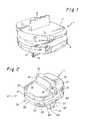
- FIG. 14is a plan view of the trial implant portion of FIG. 12 ;
- FIG. 14Ais a plan view similar to FIG. 14 , but of a trial implant of a different size.
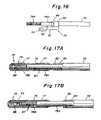
- FIG. 16is a plan view of an element of FIG. 12 , removed from the trial implant;
- FIG. 17Ais a central cross sectional view of FIG. 12 ;
- FIG. 17Bis a central cross sectional view of FIG. 13 ;
- FIG. 18is a perspective view similar to FIG. 12 but including a chisel cutting tool positioned thereon;
- FIG. 19is a perspective view illustrating an instrument for inserting trial implants
- FIG. 19Ais an enlarged perspective view of the portion of FIG. 19 shown in the broken line circle;
- FIG. 19Bis a cross sectional view of the trial implant shown in FIG. 19A ;
- FIG. 20is an end view of the trial implant of FIG. 19 , taken in the direction of the arrow C of FIG. 19A ;
- FIG. 21is a side view of the trial implant of FIG. 19 , taken in the direction of the arrow D of FIG. 19A ;
- FIG. 22is a cross sectional view of a tool which is a part of FIG. 19 ;
- FIG. 23is a cross sectional view of the trial implant taken along line 23 - 23 of FIG. 21 ;
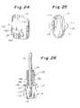
- FIG. 24is a perspective view of a burr guide
- FIG. 25is a top plan view of the burr guide shown in FIG. 24 ;
- FIG. 26is a cross sectional view of the tool of FIG. 19 showing the burr guide mounted on the trial implant;
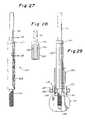
- FIG. 27is a side elevational view of a burr
- FIG. 28is a partial cross sectional view taken along line 28 - 28 of FIG. 27 ;
- FIG. 29is a cross sectional view showing the trial implant and the burr guide, together with the burr of FIG. 27 ;
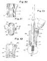
- FIG. 30is a side elevational view of another embodiment of a burr guide
- FIG. 31is a top plan view of FIG. 30 ;
- FIG. 32is a cross sectional view taken along line 32 - 32 of FIG. 31 ;
- FIG. 34is a side elevational view of a modified burr
- FIG. 35is a cross sectional view showing the burr of FIG. 34 and the burr guide of FIGS. 24 and 25 ;
- FIG. 36is a perspective view illustrating another embodiment of an instrument for inserting trial implants and another embodiment of a trial implant
- FIG. 36Ais an enlarged perspective view of the portion of FIG. 36 shown in the broken line circle;
- FIG. 37is a central cross sectional view of the trial implant shown in FIG. 36 ;
- FIG. 38is a left end view of FIG. 37 ;
- FIG. 39is a plan view of FIG. 37 ;
- FIG. 40is a plan view similar to FIG. 29 but showing a different size trial implant
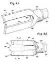
- FIG. 41is a perspective view of a chisel for use with the instrument and trial implant shown in FIGS. 36-40 ;
- FIG. 42is a side elevational view showing the modified trial implant and the chisel mounted thereon;
- FIG. 43is a side elevational view similar to FIG. 42 but showing a different size trial implant
- FIG. 44is a front perspective view of another embodiment of a cutting tool.
- FIG. 45is a longitudinal sectional view of the cutting tool of FIG. 44 ;
- FIG. 46is a cross sectional view taken along line 46 - 46 of FIG. 45 .
- the instruments and methods described hereinare applicable for preparing a wide range of artificial disc implants for insertion into an intervertebral space.
- the instruments and method described hereinwhich relate to the trial implant but which do not necessarily relate to cutting tools for forming cutouts can be used for virtually any type of artificial disc implant wherein an intervertebral space is cleaned out and an entire replacement implant is inserted into that intervertebral space.
- the instruments and methods described hereinwhich include the concept of forming cutouts to receive raised keels, the instruments and methods described herein are adaptable for use with any artificial disc implant having such keels.
- FIG. 2illustrates another implant having raised keels which are intended to be located in cutouts in the adjacent vertebrae.
- the artificial disc implant of FIG. 2can also be used for any location along the spine, including the cervical spine or the lumbar spine, this particular design has advantages for use in the cervical spine.
- the artificial disc implant 10 of FIG. 2has an upper part 11 and a lower part 30 and a plastic inlay 50 located therebetween but essentially connected to the lower part 30 .
- This plastic inlayhas a curved surface which cooperates with a curved bottom surface of upper part 11 to allow limited universal movement of the upper and lower parts relative to each other.
- the upper part 11includes an upper surface 12 , which engages and supports the adjacent vertebral surface.
- Upper surface 12is bounded by edges which are slightly beveled all the way around as shown at 13 with the largest portion of the bevel being shown along the rear surface. Below the beveled edge 13 , the upper part is bounded by a surrounding side wall 14 which has a rear support cutout 15 .
- a keel 16which includes a recess 17 formed therein. This recess is opened upwardly and rearwardly.
- the front end of keel 16comprises a V-shaped upper bevel 19 .
- the lower portion of the front end of the keelis in the form of a V-shaped bevel 20 .
- the two V-shaped bevels 19 and 20provide a front end which is “arrow” shaped in order to facilitate insertion of the keel into a cutout formed in the adjacent vertebrae.
- the rear opening of the recessis flared at 18 to anchor the rear end of the keel 16 in its cutout in the adjacent vertebrae.
- the lower part 30includes a rear support cutout 37 .
- a keel 40rises upwardly (or in the usual orientation, extends downwardly).
- This keelincludes a recess 41 which opens downwardly and rearwardly and has a flared entrance at 42 which serves the same function as flared entrance 18 , i.e., to facilitate engagement of the rear end of the keel within its cutout in the vertebrae.
- Recess 41opens downwardly and rearwardly.
- the keel 40includes a V-shaped lower bevel like that of the upper part 11 .
- a set of trial implantsmay include trial implants of approximately three different surface areas, each provided for a plurality of heights, for example three to five different heights 1 mm apart.
- the operatorwould select the trial implant which from experience the operator believes would be the most appropriate trial implant for that particular intervertebral space.
- the operatorwould start with a trial implant which, if not correct, would be on the small side.
- the operatorwould try other trial implants of the set, generally going up in height and/or surface area, as the operator deems appropriate, until finally the correct size trial implant is determined.
- the operatorneeds a mechanism for providing a physical “feel” to know when the trial implant has been inserted the proper distance into the intervertebral space.
- Known trial implantshave a fixed stop member mounted on the rear of each trial implant, which stop member would engage the vertebrae to limit movement of the trial implant into the intervertebral space. If the vertebrae has an irregularity on the anterior side thereof, or is of an irregular shape, a fixed stop might engage that irregularity and stop the trial implant before it reaches the proper position within the intervertebral space.
- the operatorafter “feeling” that the trial implant has gone as far as permitted by the current setting of the adjustable stop mechanism, and determining with instruments that the trial implant has not reached its proper position within the intervertebral space, would move the adjustable stop rearwardly to allow the trial implant to advance further into the intervertebral space.
- FIGS. 3-11Billustrate a trial implant having an adjustable stop mechanism having a movable stop member.
- the stop memberwould first be placed at its position closest to the rear of the body portion of the trial implant, thus minimizing penetration of the trial implant into the intervertebral space. Then, with the assistance of radiographic monitoring, if it was observed that the trial implant was stopped prematurely, the adjustable stop mechanism would be manipulated to gradually move the stop member away from the rear of the trial implant, allowing the trial implant to move farther into the intervertebral space until the trial implant is properly positioned therein.
- FIG. 3is a perspective view of a trial implant having an adjustable stop mechanism.
- the trial implant 51includes a body portion having a top and bottom 52 .
- a pair of front to rear slots 53may be provided in the top and bottom thereof if desired in order to cooperate with a chisel cutting tool and hence may be omitted if it is not desired or necessary to subsequently utilize a chisel cutting tool which slides along slots of a trial implant.
- the trial implant 51would be one of a plurality of trial implants of a set, as described above.
- the trial implantwould be held by a holding device.
- a rear opening 54is provided for a holding device in the form of an elongated shaft 62 which would be grasped by the operator.
- the shaft 62can be threaded into opening 54 , thereby permitting a given shaft to be used with different trial implants, or if it is believed more convenient or economical, each trial implant can be provided with a shaft 62 fixed in the opening 54 .
- the trial implanthas an elongated bore therethrough in the front to rear direction starting from a rear opening 55 to a front opening 56 .
- the rear portion 61 of this boreis smooth, i.e., not threaded, whereas the front portion 60 of this bore is threaded.
- the unthreaded smooth portion 61opens into a slotted cutout 57 which is defined above and below by parallel horizontal surfaces and at the forward end by a wall 58 which extends from the side periphery of the trial implant to an end point 59 at the juncture between the smooth portion 61 and the threaded portion 60 of the elongated bore.
- the bore itselfis shown in vertical cross section in FIG. 7 .
- FIG. 8illustrates the two parts of the adjustable stop mechanism, an adjustment member 63 and a stop member 64 .
- the adjustment member 63includes a cylindrical enlarged member 67 having a socket 66 therein for receiving a screwdriver or the like 65 (see FIG. 3 ) for turning the cylindrical member 67 and hence also the entire adjustment member 63 .
- the adjustment member 63To the left of cylindrical member 67 , the adjustment member 63 includes a smooth shaft portion 68 of reduced cross section and to the left thereof threads 69 having an outer diameter greater than the diameter of the smooth shaft 68 .
- Mounted on the adjustment member 63is the stop member 64 which comprises a hollow sleeve portion 70 which rotates freely on the smooth shaft 68 .
- the stop member 64includes at least one pin but preferably two pins, namely upper and lower pins 71 and 72 . It will be noted that the stop member 64 , while freely rotatable on the shaft 68 , is prevented from moving laterally along the adjustment member 63 , limited to the left by the larger diameter threads 69 and limited to the right by engagement of the pins 71 and 72 with the left end of cylindrical member 67 .
- the sleeve 70includes a raised rectangular lug 73 .
- FIG. 9it can been seen that if the assembly of the adjustment member and the stop member are inserted through the opening 55 and into the bore 61 until the threads 69 engage the threads 60 , continued rotational movement of the adjustment member 63 , by engaging the socket 66 with a screwdriver or the like, will cause the entire unit of the adjustment member and the stop member to advance towards and through the trial implant without necessarily rotating the stop member.
- the square lug 73is positioned to ride within the slot 57 , thereby preventing rotational movement of the stop member 64 as the entire adjustable stop mechanism advances.
- FIGS. 11A and 11BThe operation of the adjustable stop mechanism will be more evident by referring to FIGS. 11A and 11B .
- the operatorwould grasp the socket 66 with the screwdriver 65 and turn the adjustment member 63 when the threads 69 first engaged the threads 60 , in the meantime manipulating the stop member 64 rotationally to ensure that the lug 73 entered the slot 57 , thereby preventing rotational movement of the stop member 64 .
- the operatorwould then advance the adjustment member and stop member as far as possible through the bores 60 , 61 until the arms 71 and 72 were up against the back of the trial implant, at which time the lug 73 would be stopped by engagement with the end 59 of side wall 58 .
- FIG. 11Bmight represent an end position wherein the adjustment member and stop member have been pulled out, and hence the body portion of the trial implant inserted into the intervertebral space to a desired position.
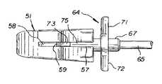
- FIGS. 12-18illustrate another embodiment of a trial implant having an adjustable stop mechanism.
- FIGS. 12 and 13are perspective views of this embodiment of a trial implant, each showing the adjustable stop mechanism in one of its two end positions.
- trial implant 74includes a body portion 75 and a tail section 76 .
- a slot 77 along the entire top and bottom of the trial implantreceives a chisel cutting tool, as will be described below.
- a shaft 78which at its remote, right-hand end would have a handle attachable thereto, includes an unthreaded middle section 78 A and a threaded forward section 78 B.
- the adjustable stop mechanism 79comprises a sleeve 80 which is freely rotatable about the shaft middle section 78 A adjacent the point where this section steps up in diameter to the main portion of shaft 78 .
- a washer 86is fixed by welding or the like to the middle shaft section 78 A. Accordingly, the sleeve 80 is mounted to rotate freely about the middle section 78 A but is prevented from moving longitudinally along shaft 78 or middle section 78 A.
- the adjustable stop mechanism 79includes an elbow portion 81 connected to the sleeve 80 and extending forwardly, whereat it is connected at its forward end to a stop member in the form of upper and lower pins 83 and 84 . These pins are of such a height as to engage the adjacent vertebrae as the trial implant is moved into an intervertebral space therebetween.
- the elbow portion 81has on its inner side a surface 82 which engages a side surface 85 of the tail section 76 such that the entire adjustable stop mechanism 79 is prevented from rotating about the axis of shaft 78 .
- trial implant 74is hollow from end to end, including an enlarged unthreaded rearward bore 87 which steps down to a smaller threaded forward bore 88 .
- FIG. 17Ashows the adjustable stop mechanism in its forwardmost position, wherein threaded section 78 B is threaded completely into the bore 88 . In this forwardmost position, the adjustable stop mechanism and hence the stop member are at their forwardmost position as shown in FIG. 12 . The forward end of threaded section 78 B is visible at the forward end of the body portion 75 .
- the operatorwould turn the shaft 78 to cause the threaded section 78 B, via its engagement with the threaded forward bore 88 to move to the right.
- the shaft 78is rotated, its middle section 78 A moves rotatably freely within the sleeve 80 , wherein the adjustable stop mechanism 79 is prevented from rotating about the axis of shaft 78 by the engagement of its wall 82 with the side wall 85 of the tail section of the trial implant.
- FIGS. 12-17Bis somewhat simplified relative to the embodiment of FIGS. 3-11B since this embodiment utilizes the already existing shaft 78 and its bore in the trial implant without the necessity for a separate bore on the side of the trial implant and a separate tool for engaging the trial implant in that second bore.
- the operation of the adjustable stop mechanism of FIGS. 12-17Bis similar to operating the adjustable stop mechanism of FIGS. 3-11B in that the adjustable stop mechanism is first moved to a position where the upper and lower pins 83 and 84 of the stop member are located at their forwardmost position closest to the body portion, thus allowing only minimal movement of the body portion into the intervertebral space.
- the operatorwould then determine whether the trial implant had moved to its proper position. If not, the operator would then move the adjustable stop mechanism 79 rearwardly. In this embodiment, the operator would simply turn the main shaft 78 , thus moving the forward shaft section 78 B rearwardly by its threaded engagement with the threaded bore 88 .
- FIGS. 13 and 17Brepresent an end position wherein the stop member has been pulled out and hence the body portion of the trial implant has been inserted into the intervertebral space to a desired position.
- the trial implant 74 of FIGS. 12-18differs from the trial implant shown in FIGS. 3 and 4 (as well as the trial implants shown in FIGS. 19-35 ) in that the former has a tail section.
- this tail sectionfunctions to provide one embodiment of an adjustable stop mechanism.
- This tail sectionhas a second function.
- the tail sectionallows a single chisel cutting tool to be usable with a plurality of different trial implants, all having the same height but having body portions of different surface areas. For example, by comparing the trial implant 74 of FIG. 14 with the trial implant 74 A of FIG. 14A , it will be seen that the trial implant 74 of FIG.
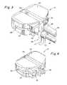
- FIG. 18illustrates a chisel cutting tool similar to that described in FIGS. 36-43 , but adapted especially for use with the trial implant and adjustable stop mechanism 79 of FIGS. 12-17B .
- FIG. 18there is shown superimposed on the trial implant 74 a chisel cutting tool 90 having an upper cutting arm 91 with a box cut front cutter 92 and a lower arm 93 with a box cut front cutter 94 .
- the chisel cutting tool shown and described below with respect to FIGS. 41-43may have a box cutting edge as shown herein or the embodiment shown in FIG. 18 may have a more standard forward cutting edge as shown in FIGS. 41-43 .
- the chisel cutting tool 90 of FIG. 18has an elongated collar 96 having a slot 97 therein for receiving the adjustable stop mechanism 79 .
- This collar 96terminates at its forward end at a throat 95 , similar to that shown in FIGS. 41-43 which engages the V-shaped indentation at the rear of the trial implant 74 .
- the upper and lower arms 91 and 93engage and move along the upper and lower slots 77 in the trial implant 74 .
- the rear end of collar 96is connected to a hollow shaft 98 which surrounds the shaft 78 so that the entire unit 90 including the arms, collar and hollow shaft 98 can move over the shaft 78 and forwardly all the way to the position shown in FIG. 18 .
- this exact chisel cutting toolwill fit both the trial implant 74 shown in FIGS. 12-15 , 17 A and 17 B, and the different size trial implant 74 A of FIG. 14A .
- FIGS. 19-23illustrate another improvement in instruments and methods for inserting a trial implant.
- the trial implantsare held on a holding device in the form of a tool 110 which has a rod 111 and a handle 112 threaded thereon. At its operative end, as shown in FIG. 22 , this insertion tool includes a threaded portion 113 .
- the trial implants 114comprise a slot 115 with an internally threaded portion 116 which threadedly receives the threaded portion 113 of the insertion tool 110 .
- the trial implantsinclude a first generally flat surface 122 and a second generally flat surface 123 .
- the posterior end thereofincludes a pair of bevels 121 and 124 .
- Each trial implant 114is provided with a pair of guide pins 117 . See FIGS. 19 , 21 and 23 . These guide pins 117 are received in a recess 118 in the trial implant 114 and they include a shoulder 119 and a narrow free end 120 .
- the userdetermines the trial implant which appears most likely to fit perfectly within the intervertebral space. That trial implant is threaded onto the end of shaft 111 of trial insertion tool 110 , after which that trial implant is inserted.
- the operatorwill eventually be able to select the correct one of the trial implants for that intervertebral space, which of course will then be used to select the actual implant to be inserted into that intervertebral space.
- the next stepis to form the cutouts in the adjacent vertebrae.
- trial implants of a fixed heightwherein a set would include a plurality of trial implants of different heights.
- trial implantswhich are adjustable in height.
- FIGS. 24-29A first embodiment of instruments for forming the cutouts are shown in FIGS. 24-29 .
- the correct trial implantOnce the correct trial implant has been selected, it is placed within the intervertebral space while mounted on shaft 111 of the insertion tool 110 .
- the handle 112is then removed by being unscrewed from shaft 111 .
- a guide 130is then slid down along the shaft 111 .
- the guideis shown in detail in FIGS. 24 and 25 . It includes an elongated slot 131 extending for most of the height of the guide 130 down to a bottom ledge 132 which has an elongated opening or slot 133 with an enlarged rounded central opening 134 .
- Guide 130includes a pair of recesses 135 in the long sides thereof with lugs 136 projecting outwardly below these recesses and with pin holes 137 extending through the lugs 136 .
- the guide 130is slid along shaft 111 until the pins 117 pass through the openings 137 with the lower ends of the lugs 136 resting on the shoulders 119 .
- the spacing along the pins 117 from the surface of the trial implant 114 to the shoulders 119is selected such that the guide 130 will come to rest at a very precise location spaced a predetermined distance from the trial implant 114 . This spacing will assure that the guide 130 will not touch the surface of the vertebrae and it will serve as a reference point for the depth of a cutting tool, as described below.
- a cutting toolis inserted.
- the cutting toolcan take different forms. For example it may be a chisel cutting tool which would be guided in elongated slot opening 133 . In the alternative, the cutting tool could be a burr cutting tool which would be guided by the elongated slot opening 133 .
- a burr cutting tool 140includes an upper rod portion 141 which is integral with its lower portion 144 and with fixed collar 142 .
- a hollow spacer sleeve 143is then slid onto the burr 140 from the end of lower portion 144 until its upper end engages the fixed collar 142 .
- the burrincludes a bump 145 thereon and the spacer sleeve 143 includes an internal circumferential groove 146 which, at any circular orientation of the spacer sleeve 143 will receive the bump 145 to fix the spacer sleeve 143 against unintended vertical movement along the burr 140 .
- the length of sleeve 143determines the exact depth of the lower portion 144 of the burr into the slot 115 which in turn determines the depth that the burr lower portion 144 will extend into the adjacent vertebrae as it subsequently forms the cutouts.
- FIG. 29This fixed depth setting of the burr is apparent from FIG. 29 wherein it is seen that the lower end of the spacer sleeve 143 abuts the ledge 132 of the guide 130 .
- FIG. 25As well as FIG. 29 , with the burr 140 positioned as shown in FIG. 29 , with the bottom of the spacer sleeve 143 resting on ledge 132 , the exact depth of the end of the burr is determined.
- FIG. 25it can be seen that with the burr positioned as shown in FIG. 29 , the end of the burr is free to move up and down in the elongated opening 133 .
- the burris driven by a power means, not shown, both in rotation and laterally up and down the elongated opening 133 . This movement then forms the cutouts in the vertebrae.
- FIGS. 30-33show another embodiment 150 of a guide for a cutting tool. Elements therein which are common to the embodiment of FIGS. 24-26 have common reference numerals.
- the guide 150includes, in place of the recesses 135 and lugs 136 a pair of central ridges 151 and 152 which run along the center outside of the wide sides of the guide 150 . At its lower ends, guide 150 is provided with a pair of pin holes 155 which are sufficiently deep to receive the pins 117 of the trial implant 114 .
- one of the central ridgesis enlarged as shown at 153 to form an angled boss which has a threaded hole 154 therein constructed to receive the threaded end 113 of a tool 110 .
- This embodimentis particularly suitable for those users of the instruments who might prefer to positively engage and move the guide, rather than permit it to fall by gravity onto the pins 117 . Also, in specific situations, it may be necessary to utilize a tool 110 for positively locating the guide rather than allowing it to fall in place by gravity.
- FIG. 33shows this guide 150 mounted on pins 117 and resting on shoulders 119 thereof of the trial implant 114 .
- the arrangement of FIG. 33is similar to FIG. 29 in the manner that a burr 140 with the spacer sleeve 143 thereon are received within the guide 150 .
- a chisel cutting toolcan be used with guide 150 .
- FIGS. 34 and 35show another embodiment of a spacer sleeve.
- the spacer sleeve 158includes a tapered upper portion 158 forming at its lower end a circular shoulder 159 surrounding a cylindrical lower portion 160 which would be of essentially the same diameter as the spacer sleeve 143 of burr 140 .
- This spacerwould also include the bump and groove structure shown in FIG. 28 .
- the advantage of this spacer sleeveis that the shoulder 159 will ride along the top of the guide. This has been found to provide greater stability than when relying only on spacer sleeve 143 riding along ledge 132 .
- FIG. 35Although the spacer sleeve of FIG. 34 is shown in FIG. 35 with the first embodiment 130 of the guide, it is to be understood that it is equally applicable for use with the guide 150 shown in FIGS. 30-33 .
- FIGS. 36-43show another embodiment of a trial implant and another embodiment of an instrument for forming the cutouts in the vertebrae.
- the trial implants 160are shaped somewhat differently than the trial implants 114 .
- These trial implants 160are similar to trial implants 114 in that they are preferably provided in the same number of sizes, and they include upper and lower surfaces 122 and 123 and bevels 121 and 124 . They are also similar to the trial implants shown in FIGS. 12-18 , but without the adjustable stop mechanism feature.
- trial implants 160differ from trial implants 114 in several respects.
- slots 166 A and 166 Bare formed along the top and bottom, respectively, of the trial implants 160 as shown in FIGS. 36-40 and for a purpose to be discussed below.
- Trial implants 160include a main body portion 162 A and a tail section 162 B with an elongated opening 163 and pin holes 164 in the top and bottom thereof.
- the insertion tool 161includes a holding device which may comprise a threadedly removable handle 112 and a shaft 161 . Shaft 161 may be threadedly engaged with the different trial implants as shown in FIGS. 19-23 . However, as an alternative, the shaft 161 may differ from shaft 111 of FIG.
- this shaft 161may engage the opening 163 and instead of being threaded, include a through pin hole 168 .
- the shaft 161is pushed into the opening 163 in the tail section 162 B until the pin hole 168 lines up with the pin holes 164 .
- a pin 165is passed through the openings 164 and 168 to secure the shaft 161 onto the trial implant 160 . Since this is an essentially permanent connection between the shaft 161 and the trial implant 160 , it means that as a general rule, each of the 15 trial implants will have a shaft fixed thereto.
- this alternative embodiment 160 of the trial implantis to cooperate with the cutting tool in the form of a chisel 180 as shown in FIGS. 41-43 form the cutouts in the vertebrae with a chisel rather than by a burr.
- the chiselincludes an upper chisel arm 181 with a sharp end 183 and a lower arm 182 with a sharp end 184 .
- the chisel 180is moved onto the trial implant 160 , moving over the shaft 161 with the facing edges of the arms 181 and 182 engaging within the slots 166 A and 166 B formed along the top and bottom of the trial implant 160 .
- a chisel for forming the cutoutis provided because in many instances the user will prefer to use a chisel to form the cutouts rather than a power driven burr.
- a plurality of trial implantsare provided, i.e., in different surface areas and each of those in different heights.
- An advantage of the present embodimentis that a single chisel can be used for all trial implants with differing surface areas and having the same height. This is accomplished by having different size tail sections, i.e., the smaller surface areas would have a larger tail section so that the total distance of the chisel in engagement with the trial implant 160 will be the same for all trial implants having the same surface area.
- each chiselincludes a V-shaped base 186 forward of an enlarged section 185 which receives a hollow shaft 187 .
- the chiselwould be moved onto the trial implant with the attached shaft 161 moving into opening 188 and through the hollow chisel shaft 187 .
- the V-shaped portions 186would fit into the V-shaped end 169 as shown in FIG. 39 .
- Trial implant 172 of FIG. 40has a larger surface area than trial implant 160 of FIG. 39 . It therefore has a shorter tail section 173 .
- the resultis that the distance from the front end of trial implant 160 to the base 170 of the V-shaped end 169 is the same as the distance from the front end of the trial implant 172 of FIG. 40 to the base 175 of the V-shaped end 174 .
- FIGS. 41 and 42show how a given chisel 180 will fit onto the trial implant 160 and the trial implant 172 .
- FIGS. 42 and 43also illustrate an outline where the upper and lower keels, such as 5 and 6 in FIG. 1 or 16 and 40 in FIG. 2 . will ultimately be located, relative to the cutouts formed by these chisels. These chisels will form cutouts with interior posterior ends which may be angled back. The ends of the chisel arms can also be straight up and down (neutral) rather than angled back.
- chisel cutting toolshas described a pair of cutting tools, one above and one below the trial implant. It is also possible to utilize a chisel having only one arm for forming a cutout in only one vertebrae or for forming two cutouts in the two adjacent vertebrae one at a time.
- FIGS. 44-46illustrate another embodiment of a chisel cutting tool for forming the cutouts in the adjacent vertebrae.
- FIGS. 44-46show a trial implant/cutting tool 190 which has a body portion having an upper surface 191 and a lower surface 192 and having upper and lower chisel arms 194 and 196 affixed thereto and extending upwardly and downwardly therefrom.
- the front edges of these upper and lower armsinclude cutting edges 195 and 197 , respectively. Forward of these cutting edges there are provided upper and lower scoop recesses 193 for receiving the cut bone chips.
- a holding device in the form of a shaft 198extends into the center of the trial implant shaped chisel cutting tool 190 , and is fixed therein by a cross pin 199 .
- the fixed shaft 198can be replaced by a shaft having a threaded end which would be threadedly and hence removably attached to the main portion of cutting tool 190 .
- the embodiments of FIGS. 44-46could be made with a single chisel arm rather than two chisel arms, which tool could then be used to cut only a single cutout in one vertebrae or to form a cutout in two adjacent vertebrae, one at a time.
- FIGS. 44-46can be used in different ways.
- the operatorcan use conventional trial implants and then, after the correct size trial implant has been determined, use the tool 190 with a body portion of the same size as the selected trial implant, to form the cutouts.
- the tool 190can be used as the actual trial implant.
- the chisel armswould cut the vertebrae to form the cutouts.
- trial implants having an adjustable stop mechanismare inserted into the intervertebral space, continuing to try different size trial implants of the set thereof, until the correct size trial implant has been selected.
- these trial implantshave had a fixed stop member for limiting movement of the initial, subsequent or final trial implant into the intervertebral space.
- each trial implanthas an adjustable stop mechanism.
- the stop member of the adjustable stop mechanismwill preferably initially be located in its position closest to the back of the body portion of the trial implant, thus allowing minimum movement of the body portion of the trial implant into the intervertebral space.
- the body portion of the trial implantmay move to the correct position within the intervertebral space with the initial setting of the adjustable stop.
- the operatorobserves the position of the trial implant within the intervertebral space. If the trial implant has not moved to the proper position, the operator moves the adjustable stop mechanism and hence its stop member rearwardly away from the back of the body portion of the trial implant, thus allowing further movement of the body portion of the trial implant into the intervertebral space.
- the adjustment rangemay allow insertion of between 1 and 10 mm into the intervertebral space. A precise manual control may be provided.
- a rotatable toolsuch as a screwdriver, wrench or the like is received in a socket or the like in the adjustable stop mechanism and calibrated such that one 360° turn can equal 1 mm of movement of the stop member and hence of depth of the trial implant.
- the stop memberis freely rotatably mounted on a adjustment member but includes a lug which engages a slot on the side of the trial implant, thus preventing rotational movement of the stop member while the operator turns the adjustable member on which it is mounted, wherein the latter threadedly engages the interior of the body portion of the trial implant, the result being that by turning the adjustable member, the assembly of the stop member and the adjustment member are moved in and out of the trial implant (or in the case of the stop member towards and away from the back of the body portion of the trial implant), with the stop member fixed against rotational movement.
- an adjustable stop mechanismis located along the side of a tail section of a trial implant, behind the body portion of the trial implant, while a sleeve thereof, located around a 90° elbow is freely rotatably mounted on the main shaft of the trial implant which is threadedly engaged within the interior of the trial implant.
- simply turning the main shaft of the trial implantmoves the adjustable stop mechanism, and hence its stop member, towards and away from the rear of the body portion of the trial implant.
- This embodimentlike the first described embodiment, can be calibrated such that one 360° turn of the main shaft can equal 1 mm of movement of the stop member and hence the depth of the trial implant. Engagement of a side wall of the adjustable stop mechanism with a side wall of the tail section of the trial implant prevents rotational movement of the adjustable stop mechanism about the axis of the main shaft.
- a trial implantis threaded onto a holding device such as a handle and inserted into the intervertebral space. If the initial trial implant is not a perfect match for the intervertebral space, then other trial implants will be tried until, through trial and error, the trial implant of the correct size has been determined. Assuming that the trial implant has a stop member mounted thereon, the handle is then threaded off of the trial implant and a guide is moved down over the shaft until the two openings in guide or the lower ends of pin holes in guide are received on the pins, further downward motion then being limited by engagement of the bottom of guide on the shoulders.
- a cutting toolwhich may be a burr or a chisel, is inserted through an elongated slot opening in the bottom of the guide.
- a cutting toolwhich may be a burr or a chisel, is inserted through an elongated slot opening in the bottom of the guide.
- the cutting toolis a burr, it includes a fixed collar and a carefully selected spacer sleeve mounted thereon which are inserted into the guide until the bottom of the spacer sleeve engages the ledge or the shoulder of spacer sleeve has engaged the top of the guide.
- the length of the spacer sleevehas been selected so that when it engages the ledge or the shoulder of spacer sleeve has engaged the top of the guide, the lower end of the burr will project downwardly for a precisely determined distance, which in turn will determine the depth of the cutout into the vertebrae.
- power meansare applied to the burr to rotate it about its axis and move it vertically so that it travels up and down along the elongated slot opening.
- the end limits of the elongated slot openingwill determine the limits of the cutouts in the vertical direction.
- a holding devicesuch as a shaft is inserted into an opening within a tail section of trial implant and secured therein.
- a holding devicesuch as a shaft is inserted into an opening within a tail section of trial implant and secured therein.
- a chiselis mounted onto the selected trial implant with the inner edges of its arms engaging slots in the top and bottom of the trial implant. Thereafter, the trial implant is moved into the intervertebral space, and as it so moves, the sharp edges of the chisel cut into the vertebrae, forming the cutouts.
- the operatorwould utilize a cutting tool having a body portion shaped like the body portion of a trial implant but having one or two chisel arms fixed thereto.
- the operatorcould proceed in one of two ways. First, the operator can use conventional trial implants and then, after the correct size trial implant has been determined, use the tool with a body portion of the same size as the selected trial implant, to form the cutouts. Second, the tool can be used as the actual trial implant. Here, as the operator tests the body portion, the chisel arms would cut the vertebrae to form the cutouts.
Landscapes
- Health & Medical Sciences (AREA)
- Orthopedic Medicine & Surgery (AREA)
- Life Sciences & Earth Sciences (AREA)
- Surgery (AREA)
- Engineering & Computer Science (AREA)
- Biomedical Technology (AREA)
- General Health & Medical Sciences (AREA)
- Veterinary Medicine (AREA)
- Heart & Thoracic Surgery (AREA)
- Public Health (AREA)
- Animal Behavior & Ethology (AREA)
- Oral & Maxillofacial Surgery (AREA)
- Nuclear Medicine, Radiotherapy & Molecular Imaging (AREA)
- Medical Informatics (AREA)
- Molecular Biology (AREA)
- Dentistry (AREA)
- Transplantation (AREA)
- Vascular Medicine (AREA)
- Cardiology (AREA)
- Physical Education & Sports Medicine (AREA)
- Neurology (AREA)
- Prostheses (AREA)
- Surgical Instruments (AREA)
Abstract
Description
Claims (39)
Priority Applications (16)
| Application Number | Priority Date | Filing Date | Title |
|---|---|---|---|
| US10/423,879US7491204B2 (en) | 2003-04-28 | 2003-04-28 | Instruments and method for preparing an intervertebral space for receiving an artificial disc implant |
| CNA2004800166321ACN1805720A (en) | 2003-04-28 | 2004-04-23 | Apparatus and method for preparing intervertebral space for receiving artificial disc implants |
| JP2006513285AJP2006524549A (en) | 2003-04-28 | 2004-04-23 | Apparatus and method for preparing an intervertebral space for receiving an artificial disc implant |
| EP04750592AEP1624833A2 (en) | 2003-04-28 | 2004-04-23 | Instruments and method for preparing an intervertebral space for receiving an artificial disc implant |
| KR1020057020596AKR20060056890A (en) | 2003-04-28 | 2004-04-23 | Apparatus and method for preparing a spinal intervertebral space for accommodating artificial disc implants |
| NZ543136ANZ543136A (en) | 2003-04-28 | 2004-04-23 | Instruments and method for preparing an intervertebral space for receiving an artificial disc implant |
| BRPI0409886-2ABRPI0409886A (en) | 2003-04-28 | 2004-04-23 | test device and implant for preparing an intervertebral space, a set of a plurality of test implants, instruments for preparing and useful in preparing an intervertebral space for receiving an implant, and, method for preparing an intervertebral space for receiving an implant |
| CNA2007101411294ACN101091664A (en) | 2003-04-28 | 2004-04-23 | Instruments and method for preparing an intervertebral space for receiving an artificial disc implant |
| CA002522991ACA2522991A1 (en) | 2003-04-28 | 2004-04-23 | Instruments and method for preparing an intervertebral space for receiving an artificial disc implant |
| PCT/US2004/012664WO2004098380A2 (en) | 2003-04-28 | 2004-04-23 | Instruments and method for preparing an intervertebral space for receiving an artificial disc implant |
| AU2004237613AAU2004237613A1 (en) | 2003-04-28 | 2004-04-23 | Instruments and method for preparing an intervertebral space for receiving an artificial disc implant |
| ARP040101426AAR044106A1 (en) | 2003-04-28 | 2004-04-27 | INSTRUMENTS AND METHOD FOR PREPARING AN INTERVERTEBRAL SPACE TO RECEIVE AN IMPLANT OF ARTIFICIAL DISK |
| ZA200508227AZA200508227B (en) | 2003-04-28 | 2005-10-12 | Instruments and method for preparing an intervertebral space for receiving an artificial disc implant |
| US11/744,013US8663229B2 (en) | 2003-04-28 | 2007-05-03 | Instruments and method for preparing an intervertebral space for receiving an artificial disc implant |
| US11/743,992US8419742B2 (en) | 2003-04-28 | 2007-05-03 | Instruments and method for preparing an intervertebral space for receiving an artificial disc implant |
| US14/151,932US10182831B2 (en) | 2003-04-28 | 2014-01-10 | Instruments and method for preparing an intervertebral space for receiving an artificial disc implant |
Applications Claiming Priority (1)
| Application Number | Priority Date | Filing Date | Title |
|---|---|---|---|
| US10/423,879US7491204B2 (en) | 2003-04-28 | 2003-04-28 | Instruments and method for preparing an intervertebral space for receiving an artificial disc implant |
Related Child Applications (2)
| Application Number | Title | Priority Date | Filing Date |
|---|---|---|---|
| US11/743,992DivisionUS8419742B2 (en) | 2003-04-28 | 2007-05-03 | Instruments and method for preparing an intervertebral space for receiving an artificial disc implant |
| US11/744,013DivisionUS8663229B2 (en) | 2003-04-28 | 2007-05-03 | Instruments and method for preparing an intervertebral space for receiving an artificial disc implant |
Publications (2)
| Publication Number | Publication Date |
|---|---|
| US20040215198A1 US20040215198A1 (en) | 2004-10-28 |
| US7491204B2true US7491204B2 (en) | 2009-02-17 |
Family
ID=33299229
Family Applications (4)
| Application Number | Title | Priority Date | Filing Date |
|---|---|---|---|
| US10/423,879Expired - LifetimeUS7491204B2 (en) | 2003-04-28 | 2003-04-28 | Instruments and method for preparing an intervertebral space for receiving an artificial disc implant |
| US11/743,992Active2028-01-01US8419742B2 (en) | 2003-04-28 | 2007-05-03 | Instruments and method for preparing an intervertebral space for receiving an artificial disc implant |
| US11/744,013Active2027-10-20US8663229B2 (en) | 2003-04-28 | 2007-05-03 | Instruments and method for preparing an intervertebral space for receiving an artificial disc implant |
| US14/151,932Active2026-06-18US10182831B2 (en) | 2003-04-28 | 2014-01-10 | Instruments and method for preparing an intervertebral space for receiving an artificial disc implant |
Family Applications After (3)
| Application Number | Title | Priority Date | Filing Date |
|---|---|---|---|
| US11/743,992Active2028-01-01US8419742B2 (en) | 2003-04-28 | 2007-05-03 | Instruments and method for preparing an intervertebral space for receiving an artificial disc implant |
| US11/744,013Active2027-10-20US8663229B2 (en) | 2003-04-28 | 2007-05-03 | Instruments and method for preparing an intervertebral space for receiving an artificial disc implant |
| US14/151,932Active2026-06-18US10182831B2 (en) | 2003-04-28 | 2014-01-10 | Instruments and method for preparing an intervertebral space for receiving an artificial disc implant |
Country Status (12)
| Country | Link |
|---|---|
| US (4) | US7491204B2 (en) |
| EP (1) | EP1624833A2 (en) |
| JP (1) | JP2006524549A (en) |
| KR (1) | KR20060056890A (en) |
| CN (2) | CN101091664A (en) |
| AR (1) | AR044106A1 (en) |
| AU (1) | AU2004237613A1 (en) |
| BR (1) | BRPI0409886A (en) |
| CA (1) | CA2522991A1 (en) |
| NZ (1) | NZ543136A (en) |
| WO (1) | WO2004098380A2 (en) |
| ZA (1) | ZA200508227B (en) |
Cited By (41)
| Publication number | Priority date | Publication date | Assignee | Title |
|---|---|---|---|---|
| US20050021042A1 (en)* | 2003-07-21 | 2005-01-27 | Theirry Marnay | Instruments and method for inserting an intervertebral implant |
| US20050267581A1 (en)* | 1999-07-02 | 2005-12-01 | Thierry Marnay | Intervertebral Implant |
| US20070016221A1 (en)* | 1999-09-14 | 2007-01-18 | Boris Beyersdorff | Insertion instrument for an intervertebral implant |
| US20070118145A1 (en)* | 2005-11-24 | 2007-05-24 | Kay Fischer | Surgical guiding instrument |
| US20070191857A1 (en)* | 2006-01-31 | 2007-08-16 | Sdgi Holdings, Inc. | Spinal disc replacement surgical instrument and methods for use in spinal disc replacement |
| US20070208346A1 (en)* | 2003-04-28 | 2007-09-06 | Theirry Marnay | Instruments and method for preparing an intervertebral space for receiving an artificial disc implant |
| US20080287997A1 (en)* | 2004-10-20 | 2008-11-20 | Moti Altarac | Interspinous spacer |
| US20080294263A1 (en)* | 2004-10-20 | 2008-11-27 | Moti Altarac | Interspinous spacer |
| US20080319550A1 (en)* | 2004-10-20 | 2008-12-25 | Moti Altarac | Interspinous spacer |
| US20090125030A1 (en)* | 2006-10-18 | 2009-05-14 | Shawn Tebbe | Dilator |
| US20090138055A1 (en)* | 2004-10-20 | 2009-05-28 | Moti Altarac | Spacer insertion instrument |
| US20090222043A1 (en)* | 2004-10-20 | 2009-09-03 | Moti Altarac | Interspinous process spacer instrument system with deployment indicator |
| US20100076443A1 (en)* | 2006-07-31 | 2010-03-25 | Rudolph Bertagnoli | Drilling/milling guide and keel cut preparation system |
| US20100168860A1 (en)* | 2008-12-22 | 2010-07-01 | Marc Reichen | Orthopedic implant with flexible keel |
| US20100280620A1 (en)* | 2009-04-15 | 2010-11-04 | Marc Reichen | Trial implant assembly |
| US20100280617A1 (en)* | 2007-01-12 | 2010-11-04 | Synthes Usa, Llc | Modular intervertebral implant |
| US20110106160A1 (en)* | 2004-10-20 | 2011-05-05 | The Board Of Trustees Of The Leland Stanford Junior University | Systems and methods for posterior dynamic stabilization of the spine |
| US8105381B2 (en) | 2002-12-13 | 2012-01-31 | Spine Solutions, Inc. | Intervertebral implant, insertion tool and method of inserting same |
| US8292922B2 (en) | 2004-10-20 | 2012-10-23 | Vertiflex, Inc. | Interspinous spacer |
| EP2556803A1 (en) | 2011-04-21 | 2013-02-13 | Synthes GmbH | Spine oriented indexing guide |
| US8740948B2 (en) | 2009-12-15 | 2014-06-03 | Vertiflex, Inc. | Spinal spacer for cervical and other vertebra, and associated systems and methods |
| US8864828B2 (en) | 2004-10-20 | 2014-10-21 | Vertiflex, Inc. | Interspinous spacer |
| US8900271B2 (en) | 2004-10-20 | 2014-12-02 | The Board Of Trustees Of The Leland Stanford Junior University | Systems and methods for posterior dynamic stabilization of the spine |
| US8998990B2 (en) | 2006-07-24 | 2015-04-07 | DePuy Synthes Products, LLC | Intervertebral implant with keel |
| US9039742B2 (en) | 2004-10-20 | 2015-05-26 | The Board Of Trustees Of The Leland Stanford Junior University | Systems and methods for posterior dynamic stabilization of the spine |
| US9119680B2 (en) | 2004-10-20 | 2015-09-01 | Vertiflex, Inc. | Interspinous spacer |
| US9125751B2 (en) | 2003-07-31 | 2015-09-08 | Globus Medical, Inc. | Transforaminal prosthetic spinal disc replacement and methods thereof |
| US9125692B2 (en) | 2004-10-20 | 2015-09-08 | The Board Of Trustees Of The Leland Stanford Junior University | Systems and methods for posterior dynamic stabilization of the spine |
| US9155572B2 (en) | 2004-10-20 | 2015-10-13 | Vertiflex, Inc. | Minimally invasive tooling for delivery of interspinous spacer |
| US9161783B2 (en) | 2004-10-20 | 2015-10-20 | Vertiflex, Inc. | Interspinous spacer |
| US9211146B2 (en) | 2004-10-20 | 2015-12-15 | The Board Of Trustees Of The Leland Stanford Junior University | Systems and methods for posterior dynamic stabilization of the spine |
| US9283005B2 (en) | 2004-10-20 | 2016-03-15 | Vertiflex, Inc. | Systems and methods for posterior dynamic stabilization of the spine |
| US9314279B2 (en) | 2004-10-20 | 2016-04-19 | The Board Of Trustees Of The Leland Stanford Junior University | Systems and methods for posterior dynamic stabilization of the spine |
| US9393055B2 (en) | 2004-10-20 | 2016-07-19 | Vertiflex, Inc. | Spacer insertion instrument |
| US9675303B2 (en) | 2013-03-15 | 2017-06-13 | Vertiflex, Inc. | Visualization systems, instruments and methods of using the same in spinal decompression procedures |
| US10231849B2 (en) | 2016-10-13 | 2019-03-19 | Warsaw Orthopedic, Inc. | Surgical instrument system and method |
| US10292738B2 (en) | 2004-10-20 | 2019-05-21 | The Board Of Trustees Of The Leland Stanford Junior University | Systems and methods for stabilizing the motion or adjusting the position of the spine |
| US10524772B2 (en) | 2014-05-07 | 2020-01-07 | Vertiflex, Inc. | Spinal nerve decompression systems, dilation systems, and methods of using the same |
| US12102542B2 (en) | 2022-02-15 | 2024-10-01 | Boston Scientific Neuromodulation Corporation | Interspinous spacer and methods and systems utilizing the interspinous spacer |
| US12390340B2 (en) | 2023-03-15 | 2025-08-19 | Boston Scientific Neuromodulation Corporation | Interspinous spacer with a range of deployment positions and methods and systems |
| US12433646B2 (en) | 2023-02-21 | 2025-10-07 | Boston Scientific Neuromodulation Corporation | Interspinous spacer with actuator locking arrangements and methods and systems |
Families Citing this family (125)
| Publication number | Priority date | Publication date | Assignee | Title |
|---|---|---|---|---|
| FR2897259B1 (en) | 2006-02-15 | 2008-05-09 | Ldr Medical Soc Par Actions Si | INTERSOMATIC TRANSFORAMINAL CAGE WITH INTERBREBAL FUSION GRAFT AND CAGE IMPLANTATION INSTRUMENT |
| CN1172634C (en)* | 1999-09-13 | 2004-10-27 | 库尔斯恩蒂斯股份公司 | Bone plating system |
| US8940047B2 (en) | 2001-02-15 | 2015-01-27 | Spinecore, Inc. | Intervertebral spacer device having recessed notch pairs for manipulation using a surgical tool |
| US6673113B2 (en) | 2001-10-18 | 2004-01-06 | Spinecore, Inc. | Intervertebral spacer device having arch shaped spring elements |
| US7223291B2 (en)* | 2001-07-16 | 2007-05-29 | Spinecore, Inc. | Intervertebral spacer device having engagement hole pairs for manipulation using a surgical tool |
| US8858564B2 (en)* | 2001-02-15 | 2014-10-14 | Spinecore, Inc. | Wedge plate inserter/impactor and related methods for use in implanting an artificial intervertebral disc |
| US7169182B2 (en)* | 2001-07-16 | 2007-01-30 | Spinecore, Inc. | Implanting an artificial intervertebral disc |
| US20070198092A1 (en)* | 2001-07-16 | 2007-08-23 | Spinecore, Inc. | System for inserting artificial intervertebral discs |
| US7635368B2 (en)* | 2001-07-16 | 2009-12-22 | Spinecore, Inc. | Intervertebral spacer device having simultaneously engageable angled perimeters for manipulation using a surgical tool |
| US7713302B2 (en) | 2001-10-01 | 2010-05-11 | Spinecore, Inc. | Intervertebral spacer device utilizing a spirally slotted belleville washer having radially spaced concentric grooves |
| US7771477B2 (en) | 2001-10-01 | 2010-08-10 | Spinecore, Inc. | Intervertebral spacer device utilizing a belleville washer having radially spaced concentric grooves |
| US20080027548A9 (en) | 2002-04-12 | 2008-01-31 | Ferree Bret A | Spacerless artificial disc replacements |
| US8038713B2 (en) | 2002-04-23 | 2011-10-18 | Spinecore, Inc. | Two-component artificial disc replacements |
| US6706068B2 (en) | 2002-04-23 | 2004-03-16 | Bret A. Ferree | Artificial disc replacements with natural kinematics |
| AU2003234508A1 (en)* | 2002-05-06 | 2003-11-17 | Warsaw Orthopedic, Inc. | Instrumentation and methods for preparation of an intervertebral space |
| JP4654125B2 (en)* | 2002-10-29 | 2011-03-16 | スパインコア,インコーポレイテッド | Instruments, methods, and functions for use in implanting an artificial disc |
| US6908484B2 (en) | 2003-03-06 | 2005-06-21 | Spinecore, Inc. | Cervical disc replacement |
| US7648509B2 (en) | 2003-03-10 | 2010-01-19 | Ilion Medical Llc | Sacroiliac joint immobilization |
| US7951176B2 (en) | 2003-05-30 | 2011-05-31 | Synthes Usa, Llc | Bone plate |
| US7713304B2 (en) | 2003-07-31 | 2010-05-11 | Globus Medical, Inc. | Transforaminal prosthetic spinal disc replacement |
| US7621956B2 (en)* | 2003-07-31 | 2009-11-24 | Globus Medical, Inc. | Prosthetic spinal disc replacement |
| US7153325B2 (en)* | 2003-08-01 | 2006-12-26 | Ultra-Kinetics, Inc. | Prosthetic intervertebral disc and methods for using the same |
| US11259851B2 (en) | 2003-08-26 | 2022-03-01 | DePuy Synthes Products, Inc. | Bone plate |
| DE20321551U1 (en) | 2003-08-26 | 2007-12-27 | Synthes Gmbh | bone plate |
| US20050154462A1 (en)* | 2003-12-02 | 2005-07-14 | St. Francis Medical Technologies, Inc. | Laterally insertable artificial vertebral disk replacement implant with translating pivot point |
| US8123757B2 (en) | 2003-12-31 | 2012-02-28 | Depuy Spine, Inc. | Inserter instrument and implant clip |
| US8574268B2 (en) | 2004-01-26 | 2013-11-05 | DePuy Synthes Product, LLC | Highly-versatile variable-angle bone plate system |
| US11291484B2 (en) | 2004-01-26 | 2022-04-05 | DePuy Synthes Products, Inc. | Highly-versatile variable-angle bone plate system |
| EP2113227B1 (en) | 2004-02-04 | 2015-07-29 | LDR Medical | Intervertebral disc prosthesis |
| US7780731B2 (en) | 2004-11-26 | 2010-08-24 | Spine Solutions, Inc. | Intervertebral implant |
| US7763024B2 (en)* | 2004-09-23 | 2010-07-27 | Spine Solutions, Inc. | Adjustable cutting of cutout in vertebral bone |
| KR20120102806A (en)* | 2004-09-23 | 2012-09-18 | 스파인 소루션 아이앤씨 | System and method for an intervertebral implant |
| US8012207B2 (en) | 2004-10-20 | 2011-09-06 | Vertiflex, Inc. | Systems and methods for posterior dynamic stabilization of the spine |
| AU2005314224B2 (en)* | 2004-12-06 | 2009-10-08 | Axiomed Spine Corporation | Method for replacing a spinal disc |
| US8277457B1 (en)* | 2004-12-09 | 2012-10-02 | Greatbatch Medical S.A. | Orthopaedic inserter using a collet mechanism |
| DE102005003096B4 (en)* | 2005-01-22 | 2013-10-17 | Aesculap Ag | Surgical instrument for preparing a vertebral body |
| US8777959B2 (en) | 2005-05-27 | 2014-07-15 | Spinecore, Inc. | Intervertebral disc and insertion methods therefor |
| US8394142B2 (en)* | 2005-06-13 | 2013-03-12 | Synthes Usa, Llc | Customizing an intervertebral implant |
| US7533672B2 (en)* | 2005-09-06 | 2009-05-19 | Synthes Usa, Llc | Methods and apparatus for vascular protection in spinal surgery |
| FR2891135B1 (en) | 2005-09-23 | 2008-09-12 | Ldr Medical Sarl | INTERVERTEBRAL DISC PROSTHESIS |
| DE102005056818A1 (en)* | 2005-11-24 | 2007-05-31 | Aesculap Ag & Co. Kg | Guiding instrument for e.g. cutter, has guiding unit designed and arranged, such that cutting tool is guided along movement path defined by guiding unit and movement path corresponds to superimposed translation-rotatable-movement |
| US20070155271A1 (en)* | 2005-12-30 | 2007-07-05 | Touzov Igor V | Heat conductive textile and method producing thereof |
| US8377072B2 (en) | 2006-02-06 | 2013-02-19 | Depuy Spine, Inc. | Medical device installation tool |
| US7875034B2 (en)* | 2006-03-14 | 2011-01-25 | Warsaw Orthopedic, Inc. | Spinal disc space preparation instruments and methods for interbody spinal implants |
| US8715350B2 (en)* | 2006-09-15 | 2014-05-06 | Pioneer Surgical Technology, Inc. | Systems and methods for securing an implant in intervertebral space |
| EP2073761B1 (en)* | 2006-09-21 | 2010-07-07 | SpineCore, Inc. | Intervertebral disc implants and tooling |
| US9381098B2 (en)* | 2006-09-28 | 2016-07-05 | Spinal Kinetics, Inc. | Tool systems for implanting prosthetic intervertebral discs |
| WO2008070863A2 (en) | 2006-12-07 | 2008-06-12 | Interventional Spine, Inc. | Intervertebral implant |
| US8465546B2 (en)* | 2007-02-16 | 2013-06-18 | Ldr Medical | Intervertebral disc prosthesis insertion assemblies |
| US20080228275A1 (en)* | 2007-03-14 | 2008-09-18 | Heather Cannon | Intervertebral implant component with three points of contact |
| US8361080B2 (en)* | 2007-03-30 | 2013-01-29 | Depuy Spine, Inc. | Implant inserter having a bifurcated adjustable stop |
| US8172848B2 (en)* | 2007-04-27 | 2012-05-08 | Spinemedica, Llc | Surgical instruments for spinal disc implants and related methods |
| US8579910B2 (en) | 2007-05-18 | 2013-11-12 | DePuy Synthes Products, LLC | Insertion blade assembly and method of use |
| FR2916956B1 (en) | 2007-06-08 | 2012-12-14 | Ldr Medical | INTERSOMATIC CAGE, INTERVERTEBRAL PROSTHESIS, ANCHORING DEVICE AND IMPLANTATION INSTRUMENTATION |
| US8900307B2 (en) | 2007-06-26 | 2014-12-02 | DePuy Synthes Products, LLC | Highly lordosed fusion cage |
| US12186201B2 (en) | 2007-07-02 | 2025-01-07 | Theken Spine, Llc | Spinal cage having deployable member |
| US8864829B1 (en) | 2007-07-02 | 2014-10-21 | Theken Spine, Llc | Spinal cage having deployable member |
| US8545562B1 (en) | 2007-07-02 | 2013-10-01 | Theken Spine, Llc | Deployable member for use with an intervertebral cage |
| US8142508B1 (en) | 2007-07-02 | 2012-03-27 | Theken Spine, Llc | Spinal cage having deployable member which is removable |
| US8292958B1 (en) | 2007-07-02 | 2012-10-23 | Theken Spine, Llc | Spinal cage having deployable member |
| US10342674B2 (en) | 2007-07-02 | 2019-07-09 | Theken Spine, Llc | Spinal cage having deployable member |
| US20090024174A1 (en) | 2007-07-17 | 2009-01-22 | Stark John G | Bone screws and particular applications to sacroiliac joint fusion |
| US8267997B2 (en) | 2007-11-12 | 2012-09-18 | Theken Spine, Llc | Vertebral interbody compression implant |
| JP5677850B2 (en) | 2007-12-28 | 2015-02-25 | シンセス ゲゼルシャフト ミット ベシュレンクテル ハフツングSynthes Gmbh | Combined body for impact driving into the patient's bone |
| US20090177195A1 (en)* | 2008-01-07 | 2009-07-09 | Spinal Kinetics, Inc. | Alignable Tools for Preparing an Intervertebral Site for Implanting a Prosthetic Intervertebral Disc and a Method for Using Those Tools |
| EP2237748B1 (en) | 2008-01-17 | 2012-09-05 | Synthes GmbH | An expandable intervertebral implant |
| AU2009205679B2 (en) | 2008-01-18 | 2013-12-05 | Spinecore, Inc. | Instruments and methods for inserting artificial intervertebral implants |
| US8740912B2 (en) | 2008-02-27 | 2014-06-03 | Ilion Medical Llc | Tools for performing less invasive orthopedic joint procedures |
| US8083796B1 (en) | 2008-02-29 | 2011-12-27 | Nuvasive, Inc. | Implants and methods for spinal fusion |
| US8936641B2 (en) | 2008-04-05 | 2015-01-20 | DePuy Synthes Products, LLC | Expandable intervertebral implant |
| US8906033B2 (en) | 2009-03-30 | 2014-12-09 | DePuy Synthes Products, LLC | Cervical motion disc inserter |
| US9526620B2 (en) | 2009-03-30 | 2016-12-27 | DePuy Synthes Products, Inc. | Zero profile spinal fusion cage |
| US9408715B2 (en) | 2009-04-15 | 2016-08-09 | DePuy Synthes Products, Inc. | Arcuate fixation member |
| US8641766B2 (en)* | 2009-04-15 | 2014-02-04 | DePuy Synthes Products, LLC | Arcuate fixation member |
| EP2432429B1 (en) | 2009-05-19 | 2016-03-30 | Synthes GmbH | Dynamic trial implants |
| CN105326585B (en)* | 2009-09-17 | 2018-12-11 | Ldr控股公司 | Intervertebral implant with extensible bone anchoring element |
| US20110125270A1 (en)* | 2009-11-23 | 2011-05-26 | David C Paul | Prosthetic Spinal Disc Replacement |
| US8277509B2 (en) | 2009-12-07 | 2012-10-02 | Globus Medical, Inc. | Transforaminal prosthetic spinal disc apparatus |
| USD622843S1 (en)* | 2009-12-08 | 2010-08-31 | Horton Kenneth L | Spinous process inserter |
| USD629896S1 (en)* | 2009-12-10 | 2010-12-28 | Horton Kenneth L | Spinous process tapered dilator |
| WO2011080535A1 (en) | 2009-12-31 | 2011-07-07 | Lrd Medical | Anchoring device, intervertebral implant and implantation instrument |
| US8808304B2 (en)* | 2010-04-21 | 2014-08-19 | Globus Medical, Inc | Insertion tool assembly |
| US8979860B2 (en) | 2010-06-24 | 2015-03-17 | DePuy Synthes Products. LLC | Enhanced cage insertion device |
| US9907560B2 (en) | 2010-06-24 | 2018-03-06 | DePuy Synthes Products, Inc. | Flexible vertebral body shavers |
| US8623091B2 (en) | 2010-06-29 | 2014-01-07 | DePuy Synthes Products, LLC | Distractible intervertebral implant |
| US20120078373A1 (en) | 2010-09-23 | 2012-03-29 | Thomas Gamache | Stand alone intervertebral fusion device |
| US11701238B2 (en) | 2011-01-06 | 2023-07-18 | Darren L. BERGEY | Compressive, orthopedic, anchoring apparatus and method |
| WO2012094647A2 (en) | 2011-01-06 | 2012-07-12 | Bergey Darren L | Interbody vertebral prosthetic device with blade anchor |
| US8545563B2 (en)* | 2011-02-02 | 2013-10-01 | DePuy Synthes Product, LLC | Intervertebral implant having extendable bone fixation members |
| US20130158666A1 (en)* | 2011-06-16 | 2013-06-20 | Zyga Technology, Inc. | Facet fusion system |
| US9017410B2 (en) | 2011-10-26 | 2015-04-28 | Globus Medical, Inc. | Artificial discs |
| US9271836B2 (en) | 2012-03-06 | 2016-03-01 | DePuy Synthes Products, Inc. | Nubbed plate |
| WO2013149134A2 (en)* | 2012-03-30 | 2013-10-03 | Olympus Biotech Corporation | Alif spinal implant |
| US9361410B2 (en)* | 2012-05-03 | 2016-06-07 | DePuy Synthes Products, Inc. | Surgical guides from scanned implant data |
| US9717601B2 (en) | 2013-02-28 | 2017-08-01 | DePuy Synthes Products, Inc. | Expandable intervertebral implant, system, kit and method |
| US9522070B2 (en) | 2013-03-07 | 2016-12-20 | Interventional Spine, Inc. | Intervertebral implant |
| US9301849B2 (en)* | 2013-03-14 | 2016-04-05 | Warsaw Orthopedic, Inc. | Endplate punch template and method of use |
| FR3005569B1 (en) | 2013-05-16 | 2021-09-03 | Ldr Medical | VERTEBRAL IMPLANT, VERTEBRAL IMPLANT FIXATION DEVICE AND IMPLANTATION INSTRUMENTATION |
| US9198770B2 (en) | 2013-07-31 | 2015-12-01 | Globus Medical, Inc. | Artificial disc devices and related methods of use |
| FR3020756B1 (en) | 2014-05-06 | 2022-03-11 | Ldr Medical | VERTEBRAL IMPLANT, VERTEBRAL IMPLANT FIXATION DEVICE AND IMPLANT INSTRUMENTATION |
| KR101498013B1 (en)* | 2014-08-14 | 2015-03-03 | 주식회사 앤트테크놀로지 | Intervertebral fusion cage combined with fixing blade |
| EP3195833B1 (en)* | 2016-01-19 | 2022-01-12 | K2M, Inc. | Surgical instrument |
| US11510788B2 (en) | 2016-06-28 | 2022-11-29 | Eit Emerging Implant Technologies Gmbh | Expandable, angularly adjustable intervertebral cages |
| EP3474784A2 (en) | 2016-06-28 | 2019-05-01 | Eit Emerging Implant Technologies GmbH | Expandable and angularly adjustable intervertebral cages with articulating joint |
| US10624686B2 (en) | 2016-09-08 | 2020-04-21 | DePuy Synthes Products, Inc. | Variable angel bone plate |
| US10820930B2 (en) | 2016-09-08 | 2020-11-03 | DePuy Synthes Products, Inc. | Variable angle bone plate |
| US10905476B2 (en) | 2016-09-08 | 2021-02-02 | DePuy Synthes Products, Inc. | Variable angle bone plate |
| US10398563B2 (en) | 2017-05-08 | 2019-09-03 | Medos International Sarl | Expandable cage |
| US10687955B2 (en)* | 2018-02-02 | 2020-06-23 | Ayman H. Al-Jazaeri | Distally expanding facet implant with integrated plate and delivery device |
| US11026727B2 (en) | 2018-03-20 | 2021-06-08 | DePuy Synthes Products, Inc. | Bone plate with form-fitting variable-angle locking hole |
| US10772665B2 (en) | 2018-03-29 | 2020-09-15 | DePuy Synthes Products, Inc. | Locking structures for affixing bone anchors to a bone plate, and related systems and methods |
| US11013541B2 (en) | 2018-04-30 | 2021-05-25 | DePuy Synthes Products, Inc. | Threaded locking structures for affixing bone anchors to a bone plate, and related systems and methods |
| US10925651B2 (en) | 2018-12-21 | 2021-02-23 | DePuy Synthes Products, Inc. | Implant having locking holes with collection cavity for shavings |
| USD904609S1 (en) | 2019-04-09 | 2020-12-08 | Paragon 28, Inc. | Cutting guide |
| USD904610S1 (en)* | 2019-04-09 | 2020-12-08 | Paragon 28, Inc. | Cutting guide |
| USD915588S1 (en)* | 2019-04-09 | 2021-04-06 | Paragon 28, Inc. | Cutting guide |
| US11000384B2 (en) | 2019-10-15 | 2021-05-11 | Ayman H. Al-Jazaeri | Distally expanding facet joint implant and delivery device |
| US11426286B2 (en) | 2020-03-06 | 2022-08-30 | Eit Emerging Implant Technologies Gmbh | Expandable intervertebral implant |
| US20220008211A1 (en)* | 2020-07-08 | 2022-01-13 | Ctl Medical Corporation | Cage with keel |
| US20220008215A1 (en)* | 2020-07-08 | 2022-01-13 | Ctl Medical Corporation | Spinal cage with keel |
| US11850160B2 (en) | 2021-03-26 | 2023-12-26 | Medos International Sarl | Expandable lordotic intervertebral fusion cage |
| US11752009B2 (en) | 2021-04-06 | 2023-09-12 | Medos International Sarl | Expandable intervertebral fusion cage |
| US12090064B2 (en) | 2022-03-01 | 2024-09-17 | Medos International Sarl | Stabilization members for expandable intervertebral implants, and related systems and methods |
| US12324753B2 (en)* | 2022-10-05 | 2025-06-10 | Warsaw Orthopedic, Inc. | Interbody trial instrument with screw trajectory indicators |
| US12251325B1 (en)* | 2024-10-03 | 2025-03-18 | Universal Spine, LLC | Adjustable trial spacer system |
Citations (27)
| Publication number | Priority date | Publication date | Assignee | Title |
|---|---|---|---|---|
| US4697586A (en) | 1986-06-24 | 1987-10-06 | Gazale William J | Combined chisel-guide surgical instrument |
| US4878915A (en)* | 1987-01-22 | 1989-11-07 | Brantigan John W | Surgical prosthetic implant facilitating vertebral interbody fusion |
| US5314477A (en) | 1990-03-07 | 1994-05-24 | J.B.S. Limited Company | Prosthesis for intervertebral discs and instruments for implanting it |
| FR2718635A1 (en) | 1994-04-15 | 1995-10-20 | Axcyl Medical | Vertebral cervical prosthesis |
| US5522899A (en)* | 1988-06-28 | 1996-06-04 | Sofamor Danek Properties, Inc. | Artificial spinal fusion implants |
| US5554191A (en)* | 1994-01-26 | 1996-09-10 | Biomat | Intersomatic vertebral cage |
| US5571109A (en) | 1993-08-26 | 1996-11-05 | Man Ceramics Gmbh | System for the immobilization of vertebrae |
| FR2737656A1 (en) | 1995-08-09 | 1997-02-14 | Jbs Sa | IMPACTOR DEVICE FOR PLACING A PROSTHESIS FOR INTERVERTEBRAL DISCS |
| US5716415A (en) | 1993-10-01 | 1998-02-10 | Acromed Corporation | Spinal implant |
| US5885299A (en)* | 1994-09-15 | 1999-03-23 | Surgical Dynamics, Inc. | Apparatus and method for implant insertion |
| US6042582A (en) | 1997-05-20 | 2000-03-28 | Ray; Charles D. | Instrumentation and method for facilitating insertion of spinal implant |
| US6080155A (en)* | 1988-06-13 | 2000-06-27 | Michelson; Gary Karlin | Method of inserting and preloading spinal implants |
| WO2001001893A1 (en) | 1999-07-02 | 2001-01-11 | Spine Solutions Inc. | Intervertebral implant |
| WO2001019295A1 (en) | 1999-09-14 | 2001-03-22 | Spine Solutions Inc. | Instrument for inserting intervertebral implants |
| US20010010002A1 (en) | 1999-01-25 | 2001-07-26 | Michelson Gary K. | Instrumentation and method for creating an intervertebral space for receiving an implant |
| US6309421B1 (en) | 1994-03-18 | 2001-10-30 | Madhavan Pisharodi | Rotating, locking intervertebral disk stabilizer and applicator |
| US20020016633A1 (en) | 2000-07-26 | 2002-02-07 | Jo-Wen Lin | Intervertebral spacer and implant insertion instrumentation |
| US20020099377A1 (en) | 1998-10-20 | 2002-07-25 | Zucherman James F. | Mating insertion instruments for spinal implants and methods of use |
| US20020111679A1 (en) | 1998-10-20 | 2002-08-15 | Zucherman James F. | Apparatus and method for determining implant size |
| US6436098B1 (en) | 1993-06-10 | 2002-08-20 | Sofamor Danek Holdings, Inc. | Method for inserting spinal implants and for securing a guard to the spine |
| US20020120259A1 (en) | 1995-06-07 | 2002-08-29 | Lettice John J. | Methods for targeted electrosurgery on contained herniated discs |
| US20020165612A1 (en) | 2001-05-03 | 2002-11-07 | David Gerber | Intervertebral implant for transforaminal posterior lumbar interbody fusion procedure |
| US6478800B1 (en) | 2000-05-08 | 2002-11-12 | Depuy Acromed, Inc. | Medical installation tool |
| US6517544B1 (en) | 1998-06-09 | 2003-02-11 | Gary K. Michelson | Device and method for preparing a space between adjacent vertebrae to receive an insert |
| US6524318B1 (en) | 1999-10-18 | 2003-02-25 | Sulzer Spine-Tech Inc. | Spinal surgery instruments and methods |
| US20030045884A1 (en) | 2001-09-04 | 2003-03-06 | Bruce Robie | Instrument and system for preparing the disc space between two vertebral bodies |
| US20030055434A1 (en) | 2001-09-20 | 2003-03-20 | O'neil Michael J. | Medical inserter tool with slaphammer |
Family Cites Families (277)
| Publication number | Priority date | Publication date | Assignee | Title |
|---|---|---|---|---|
| US114816A (en)* | 1871-05-16 | Improvement in carriage-jacks | ||
| US401335A (en)* | 1889-04-16 | Hand-stamp | ||
| GB1030145A (en) | 1964-04-21 | 1966-05-18 | Paul Wittebol | Improvements in or relating to femoral prostheses |
| US3486505A (en) | 1967-05-22 | 1969-12-30 | Gordon M Morrison | Orthopedic surgical instrument |
| US3510883A (en) | 1967-10-30 | 1970-05-12 | Robert F Cathcart | Joint prosthesis |
| BE757681A (en)* | 1970-01-22 | 1971-04-01 | Sampson Arnold | IMPROVEMENTS TO DENTAL PROSTHESIS DEVICES |
| US3740769A (en) | 1971-02-11 | 1973-06-26 | E Haboush | Prosthesis for hip joints |
| DE2263842A1 (en) | 1972-12-28 | 1974-07-04 | Hoffmann Daimler Siegfried Dr | DISC PROTHESIS |
| JPS552966Y2 (en) | 1974-02-08 | 1980-01-24 | ||
| US3875595A (en)* | 1974-04-15 | 1975-04-08 | Edward C Froning | Intervertebral disc prosthesis and instruments for locating same |
| US3903549A (en) | 1974-06-12 | 1975-09-09 | William Minor Deyerle | Acetabular cup prosthesis component for total or subtotal hip prosthesis system |
| USD243286S (en) | 1975-06-02 | 1977-02-01 | William Minor Deyerle | Femoral hip prosthesis component for total and sub-total hip replacement systems |
| US4034746A (en)* | 1975-08-01 | 1977-07-12 | Williams Robert W | Retractor |
| US4038897A (en) | 1975-10-14 | 1977-08-02 | Electronic Music Laboratories, Inc. | Electronic music system and stringed instrument input device therefor |
| US4021864A (en)* | 1976-04-14 | 1977-05-10 | The Regents Of The University Of California | Ankle prosthesis |
| GB1579773A (en) | 1977-07-18 | 1980-11-26 | Nat Res Dev | Endoprosthetic bone joint devices |
| CH624573A5 (en) | 1978-02-01 | 1981-08-14 | Sulzer Ag | Intervertebral prosthesis |
| US4470158A (en) | 1978-03-10 | 1984-09-11 | Biomedical Engineering Corp. | Joint endoprosthesis |
| US4239045A (en) | 1979-04-04 | 1980-12-16 | Schlein Allen P | Surgical knife |
| DE2914455A1 (en) | 1979-04-10 | 1980-10-23 | Maschf Augsburg Nuernberg Ag | DEVICE FOR PRODUCING A COLLECTION IN A BONE |
| CH640131A5 (en) | 1979-10-03 | 1983-12-30 | Sulzer Ag | Complete intervertebral prosthesis |
| DE3012447C2 (en) | 1980-03-31 | 1982-04-01 | Harald 7200 Tuttlingen Maslanka | Surgical grasper instrument |
| CA1146301A (en) | 1980-06-13 | 1983-05-17 | J. David Kuntz | Intervertebral disc prosthesis |
| US4309777A (en)* | 1980-11-13 | 1982-01-12 | Patil Arun A | Artificial intervertebral disc |
| EP0077159A1 (en) | 1981-10-14 | 1983-04-20 | Brian Norman Atkins | Vertebrae spreader |
| US4770661A (en) | 1982-01-18 | 1988-09-13 | Indong Oh | Conversion femoral endoprosthesis |
| US4545374A (en) | 1982-09-03 | 1985-10-08 | Jacobson Robert E | Method and instruments for performing a percutaneous lumbar diskectomy |
| US4681589A (en) | 1984-06-01 | 1987-07-21 | Tronzo Raymond G | Adjustable acetabular cup prosthesis as part of a total cup replacement system |
| US4736738A (en)* | 1984-07-09 | 1988-04-12 | Matej Lipovsek | Instrument kit and procedure for performing posterior lumbar interbody fusion |
| US4550450A (en) | 1984-07-24 | 1985-11-05 | Kinnett James G | Total shoulder prosthesis system |
| EP0176728B1 (en)* | 1984-09-04 | 1989-07-26 | Humboldt-Universität zu Berlin | Intervertebral-disc prosthesis |
| US4622959A (en) | 1985-03-05 | 1986-11-18 | Marcus Randall E | Multi-use femoral intramedullary nail |
| DE3526742A1 (en) | 1985-07-26 | 1987-01-29 | Volkmar Dipl Ing Jansson | Guide sleeve with a striker for driving (bone) chips in bone |
| US4653487A (en) | 1986-01-29 | 1987-03-31 | Maale Gerhard E | Intramedullary rod assembly for cement injection system |
| GB8620937D0 (en) | 1986-08-29 | 1986-10-08 | Shepperd J A N | Spinal implant |
| DE3707097A1 (en)* | 1986-12-05 | 1988-06-09 | S & G Implants Gmbh | PLIERS FOR SPREADING SPINE BODIES |
| CA1283501C (en) | 1987-02-12 | 1991-04-30 | Thomas P. Hedman | Artificial spinal disc |
| US4714469A (en) | 1987-02-26 | 1987-12-22 | Pfizer Hospital Products Group, Inc. | Spinal implant |
| JPH01136655A (en) | 1987-11-24 | 1989-05-29 | Asahi Optical Co Ltd | Movable type pyramid spacer |
| US4805607A (en) | 1987-12-03 | 1989-02-21 | Boehringer Mannheim Corporation | Modular intramedullary nail system |
| US4874389A (en) | 1987-12-07 | 1989-10-17 | Downey Ernest L | Replacement disc |
| US4875474A (en) | 1988-01-29 | 1989-10-24 | Biomet, Inc. | Variable wall thickness interlocking intramedullary nail |
| US4827928A (en) | 1988-02-01 | 1989-05-09 | Collis Jr John S | Surgical instrument |
| DE3809793A1 (en)* | 1988-03-23 | 1989-10-05 | Link Waldemar Gmbh Co | SURGICAL INSTRUMENT SET |
| US4936863A (en) | 1988-05-13 | 1990-06-26 | Hofmann Aaron A | Hip prosthesis |
| DE8807485U1 (en) | 1988-06-06 | 1989-08-10 | Mecron Medizinische Produkte Gmbh, 1000 Berlin | Intervertebral disc endoprosthesis |
| US6770074B2 (en) | 1988-06-13 | 2004-08-03 | Gary Karlin Michelson | Apparatus for use in inserting spinal implants |
| US5015247A (en) | 1988-06-13 | 1991-05-14 | Michelson Gary K | Threaded spinal implant |
| US5484437A (en)* | 1988-06-13 | 1996-01-16 | Michelson; Gary K. | Apparatus and method of inserting spinal implants |
| US4892545A (en) | 1988-07-14 | 1990-01-09 | Ohio Medical Instrument Company, Inc. | Vertebral lock |
| US4881534A (en) | 1988-10-03 | 1989-11-21 | Uhl Richard L | Corticotomo osteotome with T-shaped cutting end |
| CA1318469C (en) | 1989-02-15 | 1993-06-01 | Acromed Corporation | Artificial disc |
| JPH02261446A (en) | 1989-04-03 | 1990-10-24 | Kawasaki Steel Corp | Artificial vertebra |
| DE3921973C1 (en)* | 1989-07-04 | 1990-10-31 | Rainer Dr. 8000 Muenchen De Baumgart | |
| US5037438A (en) | 1989-07-25 | 1991-08-06 | Richards Medical Company | Zirconium oxide coated prosthesis for wear and corrosion resistance |
| US4932975A (en) | 1989-10-16 | 1990-06-12 | Vanderbilt University | Vertebral prosthesis |
| DE8912648U1 (en)* | 1989-10-23 | 1990-11-22 | Mecron Medizinische Produkte Gmbh, 1000 Berlin | Vertebral body implant |
| US5004476A (en) | 1989-10-31 | 1991-04-02 | Tulane University | Porous coated total hip replacement system |
| US5062850A (en) | 1990-01-16 | 1991-11-05 | University Of Florida | Axially-fixed vertebral body prosthesis and method of fixation |
| US5236460A (en) | 1990-02-12 | 1993-08-17 | Midas Rex Pneumatic Tools, Inc. | Vertebral body prosthesis |
| US5167725A (en) | 1990-08-01 | 1992-12-01 | Ultracision, Inc. | Titanium alloy blade coupler coated with nickel-chrome for ultrasonic scalpel |
| DE59100448D1 (en) | 1990-04-20 | 1993-11-11 | Sulzer Ag | Implant, in particular intervertebral prosthesis. |
| US6006174A (en) | 1990-10-03 | 1999-12-21 | Interdigital Technology Coporation | Multiple impulse excitation speech encoder and decoder |
| US5336232A (en) | 1991-03-14 | 1994-08-09 | United States Surgical Corporation | Approximating apparatus for surgical jaw structure and method of using the same |
| US5192327A (en) | 1991-03-22 | 1993-03-09 | Brantigan John W | Surgical prosthetic implant for vertebrae |
| US5108442A (en) | 1991-05-09 | 1992-04-28 | Boehringer Mannheim Corporation | Prosthetic implant locking assembly |
| GB9110778D0 (en)* | 1991-05-18 | 1991-07-10 | Middleton Jeffrey K | Apparatus for use in surgery |
| US5228455A (en)* | 1991-05-20 | 1993-07-20 | Siemens Pacesetter, Inc. | Implant tool for extendable/retractable positive fixation lead |
| US5135528A (en) | 1991-06-04 | 1992-08-04 | Frederick Winston | Hockey stick chisel |
| US5282868A (en) | 1991-06-17 | 1994-02-01 | Andre Bahler | Prosthetic arrangement for a complex joint, especially knee joint |
| US5383888A (en)* | 1992-02-12 | 1995-01-24 | United States Surgical Corporation | Articulating endoscopic surgical apparatus |
| US5290312A (en) | 1991-09-03 | 1994-03-01 | Alphatec | Artificial vertebral body |
| US5395317A (en)* | 1991-10-30 | 1995-03-07 | Smith & Nephew Dyonics, Inc. | Unilateral biportal percutaneous surgical procedure |
| GB9125798D0 (en)* | 1991-12-04 | 1992-02-05 | Customflex Limited | Improvements in or relating to spinal vertebrae implants |
| US5258031A (en) | 1992-01-06 | 1993-11-02 | Danek Medical | Intervertebral disk arthroplasty |
| US5425773A (en) | 1992-01-06 | 1995-06-20 | Danek Medical, Inc. | Intervertebral disk arthroplasty device |
| US5509934A (en) | 1992-02-28 | 1996-04-23 | Osteonics Corp. | Prosthetic knee tibial component constructed of synthetic polymeric material |
| DE4208116C2 (en)* | 1992-03-13 | 1995-08-03 | Link Waldemar Gmbh Co | Intervertebral disc prosthesis |
| DE4208115A1 (en) | 1992-03-13 | 1993-09-16 | Link Waldemar Gmbh Co | DISC ENDOPROTHESIS |
| EP0566810B1 (en) | 1992-04-21 | 1996-08-14 | SULZER Medizinaltechnik AG | Artificial spinal disc |
| US5306309A (en)* | 1992-05-04 | 1994-04-26 | Calcitek, Inc. | Spinal disk implant and implantation kit |
| US6102954A (en) | 1992-05-18 | 2000-08-15 | Astra Aktiebolag | Joint prosthesis and apparatus for preparing the bone prior to fitting of the prosthesis |
| US5423825A (en)* | 1992-06-10 | 1995-06-13 | Levine; Andrew S. | Spinal fusion instruments and methods |
| US5344458A (en) | 1992-08-06 | 1994-09-06 | Bonutti Peter M | Arthroplasty component |
| US5271737A (en) | 1992-09-04 | 1993-12-21 | U.S. Medical Products, Inc. | Tibial prosthetic implant with offset stem |
| JPH06178787A (en) | 1992-12-14 | 1994-06-28 | Shima Yumiko | Centrum spacer with joint, intervertebral cavity measuring device and centrum spacer pattern |
| US5676701A (en) | 1993-01-14 | 1997-10-14 | Smith & Nephew, Inc. | Low wear artificial spinal disc |
| EP0610837B1 (en) | 1993-02-09 | 2001-09-05 | Acromed Corporation | Spine disc |
| CA2155422C (en)* | 1993-02-10 | 2005-07-12 | Stephen D. Kuslich | Spinal stabilization surgical method |
| US5326366A (en) | 1993-02-16 | 1994-07-05 | Wright Medical Technology, Inc. | Biomechanical great toe implant |
| US5364397A (en) | 1993-06-01 | 1994-11-15 | Zimmer, Inc. | Spinal coupler seater with dual jaws and an independent plunger |
| US5501654A (en)* | 1993-07-15 | 1996-03-26 | Ethicon, Inc. | Endoscopic instrument having articulating element |
| US5409492A (en)* | 1993-08-09 | 1995-04-25 | Stelkast Incorporated | System for coupling an implant to a tool for inserting and removing the implant |
| US5458641A (en) | 1993-09-08 | 1995-10-17 | Ramirez Jimenez; Juan J. | Vertebral body prosthesis |
| US5443514A (en) | 1993-10-01 | 1995-08-22 | Acromed Corporation | Method for using spinal implants |
| US5431658A (en)* | 1994-02-14 | 1995-07-11 | Moskovich; Ronald | Facilitator for vertebrae grafts and prostheses |
| US5507817A (en) | 1994-02-22 | 1996-04-16 | Kirschner Medical Corporation | Modular humeral prosthesis for reconstruction of the humerus |
| US5658347A (en) | 1994-04-25 | 1997-08-19 | Sarkisian; James S. | Acetabular cup with keel |
| JP3509103B2 (en) | 1994-05-23 | 2004-03-22 | スルザー スパイン−テック インコーポレイテッド | Intervertebral fusion implant |
| DE9413471U1 (en) | 1994-08-20 | 1995-12-21 | Schäfer micomed GmbH, 73614 Schorndorf | Ventral intervertebral implant |
| FR2724108B1 (en) | 1994-09-02 | 1997-01-17 | Jbs Sa | JOINT PROSTHESIS |
| US6033405A (en)* | 1994-09-15 | 2000-03-07 | Surgical Dynamics, Inc. | Apparatus and method for implant insertion |
| US5562736A (en) | 1994-10-17 | 1996-10-08 | Raymedica, Inc. | Method for surgical implantation of a prosthetic spinal disc nucleus |
| US5591235A (en) | 1995-03-15 | 1997-01-07 | Kuslich; Stephen D. | Spinal fixation device |
| ES2236792T3 (en) | 1995-03-27 | 2005-07-16 | Sdgi Holdings, Inc. | IMPLANTS OF SPINAL FUSION AND INSTRUMENTS FOR INSERTION AND REVIEW. |
| US6245072B1 (en)* | 1995-03-27 | 2001-06-12 | Sdgi Holdings, Inc. | Methods and instruments for interbody fusion |
| US6264655B1 (en) | 1995-06-07 | 2001-07-24 | Madhavan Pisharodi | Cervical disk and spinal stabilizer |
| ES2176396T3 (en) | 1995-08-25 | 2002-12-01 | Bristol Myers Squibb Co | PROTESIC IMPLANT WITH FINS. |
| US5782830A (en)* | 1995-10-16 | 1998-07-21 | Sdgi Holdings, Inc. | Implant insertion device |
| DE19541114A1 (en) | 1995-10-26 | 1997-04-30 | Artos Med Produkte | Intervertebral implant |
| US5709683A (en) | 1995-12-19 | 1998-01-20 | Spine-Tech, Inc. | Interbody bone implant having conjoining stabilization features for bony fusion |
| FR2742653B1 (en) | 1995-12-21 | 1998-02-27 | Colorado | INTERSOMATIC VERTEBRAL CAGE |
| US5702469A (en) | 1996-01-18 | 1997-12-30 | Kinetikos Medical, Inc. | Thumb joint prosthesis and related method of implantation |
| US5722977A (en)* | 1996-01-24 | 1998-03-03 | Danek Medical, Inc. | Method and means for anterior lumbar exact cut with quadrilateral osteotome and precision guide/spacer |
| CA2199462C (en)* | 1996-03-14 | 2006-01-03 | Charles J. Winslow | Method and instrumentation for implant insertion |
| US5683465A (en) | 1996-03-18 | 1997-11-04 | Shinn; Gary Lee | Artificial intervertebral disk prosthesis |
| JP3819962B2 (en)* | 1996-04-01 | 2006-09-13 | ペンタックス株式会社 | Interbody fusion implant guide device |
| US6159214A (en) | 1996-07-31 | 2000-12-12 | Michelson; Gary K. | Milling instrumentation and method for preparing a space between adjacent vertebral bodies |
| US5782832A (en)* | 1996-10-01 | 1998-07-21 | Surgical Dynamics, Inc. | Spinal fusion implant and method of insertion thereof |
| US6171311B1 (en)* | 1996-10-18 | 2001-01-09 | Marc Richelsoph | Transverse connector |
| US6063088A (en) | 1997-03-24 | 2000-05-16 | United States Surgical Corporation | Method and instrumentation for implant insertion |
| WO1998017209A2 (en) | 1996-10-23 | 1998-04-30 | Sdgi Holdings, Inc. | Spinal spacer |
| US5895428A (en)* | 1996-11-01 | 1999-04-20 | Berry; Don | Load bearing spinal joint implant |
| US5720751A (en)* | 1996-11-27 | 1998-02-24 | Jackson; Roger P. | Tools for use in seating spinal rods in open ended implants |
| US5951564A (en) | 1996-12-18 | 1999-09-14 | Bristol-Myers Squibb Company | Orthopaedic positioning apparatus |
| WO1998034552A1 (en) | 1997-02-06 | 1998-08-13 | Surgical Dynamics | Expandable non-threaded spinal fusion device |
| US5810878A (en)* | 1997-02-12 | 1998-09-22 | Sdgi Holdings, Inc. | Rod introducer forceps |
| US5897593A (en)* | 1997-03-06 | 1999-04-27 | Sulzer Spine-Tech Inc. | Lordotic spinal implant |
| US6641614B1 (en) | 1997-05-01 | 2003-11-04 | Spinal Concepts, Inc. | Multi-variable-height fusion device |
| USD401335S (en) | 1997-07-28 | 1998-11-17 | Tibor Koros | Combined cervical and lumbar extractor and injector surgical instrument |
| US6146421A (en) | 1997-08-04 | 2000-11-14 | Gordon, Maya, Roberts And Thomas, Number 1, Llc | Multiple axis intervertebral prosthesis |
| FR2767675B1 (en) | 1997-08-26 | 1999-12-03 | Materiel Orthopedique En Abreg | INTERSOMATIC IMPLANT AND ANCILLARY OF PREPARATION SUITABLE FOR ALLOWING ITS POSITION |
| US6059790A (en)* | 1997-08-29 | 2000-05-09 | Sulzer Spine-Tech Inc. | Apparatus and method for spinal stabilization |
| US6086595A (en) | 1997-08-29 | 2000-07-11 | Sulzer Spine-Tech Inc. | Apparatus and method for spinal stabilization |
| US5865848A (en) | 1997-09-12 | 1999-02-02 | Artifex, Ltd. | Dynamic intervertebral spacer and method of use |
| US5824094A (en) | 1997-10-17 | 1998-10-20 | Acromed Corporation | Spinal disc |
| DE19748369C2 (en) | 1997-11-03 | 2003-08-21 | Medi Plus Instr Gmbh & Co Kg | Surgical sliding shaft instrument |
| US5888226A (en)* | 1997-11-12 | 1999-03-30 | Rogozinski; Chaim | Intervertebral prosthetic disc |
| US5899941A (en)* | 1997-12-09 | 1999-05-04 | Chubu Bearing Kabushiki Kaisha | Artificial intervertebral disk |
| US6159215A (en) | 1997-12-19 | 2000-12-12 | Depuy Acromed, Inc. | Insertion instruments and method for delivering a vertebral body spacer |
| FR2774581B1 (en) | 1998-02-10 | 2000-08-11 | Dimso Sa | INTEREPINOUS STABILIZER TO BE ATTACHED TO SPINOUS APOPHYSIS OF TWO VERTEBRES |
| GB9804473D0 (en) | 1998-03-02 | 1998-04-29 | Benoist Girard & Cie | Prosthesis inserter |
| WO1999049818A1 (en) | 1998-03-30 | 1999-10-07 | Marchosky J Alexander | Prosthetic system |
| US6835208B2 (en) | 1998-03-30 | 2004-12-28 | J. Alexander Marchosky | Prosthetic system |
| US6019792A (en) | 1998-04-23 | 2000-02-01 | Cauthen Research Group, Inc. | Articulating spinal implant |
| US6241769B1 (en) | 1998-05-06 | 2001-06-05 | Cortek, Inc. | Implant for spinal fusion |
| US6171339B1 (en) | 1998-05-19 | 2001-01-09 | Sulzer Spine-Tech Inc. | Multi-lumen spinal implant guide and method |
| US6251140B1 (en) | 1998-05-27 | 2001-06-26 | Nuvasive, Inc. | Interlocking spinal inserts |
| US6083228A (en)* | 1998-06-09 | 2000-07-04 | Michelson; Gary K. | Device and method for preparing a space between adjacent vertebrae to receive an insert |
| EP1090250A1 (en)* | 1998-06-17 | 2001-04-11 | Medi-Physics, Inc. | Hyperpolarized gas transport device and associated transport method |
| US6063121A (en) | 1998-07-29 | 2000-05-16 | Xavier; Ravi | Vertebral body prosthesis |
| US6126660A (en) | 1998-07-29 | 2000-10-03 | Sofamor Danek Holdings, Inc. | Spinal compression and distraction devices and surgical methods |
| US6017342A (en)* | 1998-08-05 | 2000-01-25 | Beere Precision Medical Instrumnets, Inc. | Compression and distraction instrument |
| DE29814174U1 (en) | 1998-08-07 | 1999-12-16 | Howmedica GmbH, 24232 Schönkirchen | Instruments for inserting an implant into the human spine |
| US6117174A (en) | 1998-09-16 | 2000-09-12 | Nolan; Wesley A. | Spinal implant device |
| AU760821B2 (en)* | 1998-10-02 | 2003-05-22 | Synthes Gmbh | Spinal disc space distractor |
| US7189234B2 (en)* | 1998-10-20 | 2007-03-13 | St. Francis Medical Technologies, Inc. | Interspinous process implant sizer and distractor with a split head and size indicator and method |
| US6113637A (en) | 1998-10-22 | 2000-09-05 | Sofamor Danek Holdings, Inc. | Artificial intervertebral joint permitting translational and rotational motion |
| US6174311B1 (en) | 1998-10-28 | 2001-01-16 | Sdgi Holdings, Inc. | Interbody fusion grafts and instrumentation |
| US6254318B1 (en)* | 1998-12-16 | 2001-07-03 | Michael F. Sica | Apparatus for making numerous holes in a tube |
| US6102950A (en) | 1999-01-19 | 2000-08-15 | Vaccaro; Alex | Intervertebral body fusion device |
| DE19903762C1 (en)* | 1999-01-30 | 2000-11-16 | Aesculap Ag & Co Kg | Surgical instrument for inserting intervertebral implants |
| CA2361068A1 (en) | 1999-02-04 | 2000-08-10 | Sdgi Holdings, Inc. | Improved interbody fusion device with anti-rotation features |
| US6648895B2 (en) | 2000-02-04 | 2003-11-18 | Sdgi Holdings, Inc. | Methods and instrumentation for vertebral interbody fusion |
| AU761818C (en) | 1999-02-04 | 2004-05-27 | Warsaw Orthopedic, Inc. | Methods and instrumentation for vertebral interbody fusion |
| US6368353B1 (en) | 1999-02-24 | 2002-04-09 | Michel A. Arcand | Shoulder prosthesis apparatus and methods |
| US6113638A (en) | 1999-02-26 | 2000-09-05 | Williams; Lytton A. | Method and apparatus for intervertebral implant anchorage |
| US6368350B1 (en)* | 1999-03-11 | 2002-04-09 | Sulzer Spine-Tech Inc. | Intervertebral disc prosthesis and method |
| US6113602A (en) | 1999-03-26 | 2000-09-05 | Sulzer Spine-Tech Inc. | Posterior spinal instrument guide and method |
| US6733505B2 (en)* | 2000-04-26 | 2004-05-11 | Sdgi Holdings, Inc. | Apparatus and method for loading a prosthetic nucleus into a deployment cannula to replace the nucleus pulposus of an intervertebral disc |
| WO2000069347A1 (en) | 1999-05-12 | 2000-11-23 | Medical Sterile Products, Inc. | Corrugated osteotome blade and method of severing bones and other anatomical structures |
| US6224599B1 (en)* | 1999-05-19 | 2001-05-01 | Matthew G. Baynham | Viewable wedge distractor device |
| AU770261B2 (en)* | 1999-06-04 | 2004-02-19 | Warsaw Orthopedic, Inc. | Artificial disc implant |
| US6295834B1 (en)* | 1999-06-30 | 2001-10-02 | Medi-Physics, Inc. | NMR polarization monitoring coils, hyperpolarizers with same, and methods for determining the polarization level of accumulated hyperpolarized noble gases during production |
| FR2795945B1 (en) | 1999-07-09 | 2001-10-26 | Scient X | ANATOMICAL INTERSOMATIC IMPLANT AND GRIPPER FOR SUCH AN IMPLANT |
| FR2797179B1 (en) | 1999-08-03 | 2002-03-08 | Michel Gau | INTERVERTEBRAL NUCLEAR PROSTHESIS AND SURGICAL IMPLANTATION METHOD |
| DE60030989T2 (en) | 1999-08-26 | 2007-05-24 | Warsaw Orthopedic, Inc., Warsaw | DEVICE FOR IMPLANTING FUSION CAGE |
| US6238414B1 (en)* | 2000-01-20 | 2001-05-29 | Jerry R. Griffiths | Laparoscopic instrument with parallel actuated jaws |
| DE60104286T2 (en) | 2000-02-22 | 2005-07-28 | SDGI Holdings, Inc., Wilmington | CUTLERY FOR PREPARING THE INTERMEDIATE ROOM |
| FR2805985B1 (en) | 2000-03-10 | 2003-02-07 | Eurosurgical | INTERVERTEBRAL DISK PROSTHESIS |
| US7169183B2 (en) | 2000-03-14 | 2007-01-30 | Warsaw Orthopedic, Inc. | Vertebral implant for promoting arthrodesis of the spine |
| US6350283B1 (en) | 2000-04-19 | 2002-02-26 | Gary K. Michelson | Bone hemi-lumbar interbody spinal implant having an asymmetrical leading end and method of installation thereof |
| US6579318B2 (en) | 2000-06-12 | 2003-06-17 | Ortho Development Corporation | Intervertebral spacer |
| US7018416B2 (en) | 2000-07-06 | 2006-03-28 | Zimmer Spine, Inc. | Bone implants and methods |
| US6641582B1 (en)* | 2000-07-06 | 2003-11-04 | Sulzer Spine-Tech Inc. | Bone preparation instruments and methods |
| CA2429246C (en) | 2000-08-08 | 2011-06-07 | Vincent Bryan | Implantable joint prosthesis |
| US6824565B2 (en) | 2000-09-08 | 2004-11-30 | Nabil L. Muhanna | System and methods for inserting a vertebral spacer |
| US6679886B2 (en) | 2000-09-01 | 2004-01-20 | Synthes (Usa) | Tools and methods for creating cavities in bone |
| US6500206B1 (en) | 2000-09-15 | 2002-12-31 | Donald W. Bryan | Instruments for inserting spinal vertebral implant |
| ATE334644T1 (en)* | 2000-10-11 | 2006-08-15 | Michael D Mason | INTEGRATED FUSION DEVICE |
| US6599291B1 (en) | 2000-10-20 | 2003-07-29 | Sdgi Holdings, Inc. | Methods and instruments for interbody surgical techniques |
| US6692501B2 (en) | 2000-12-14 | 2004-02-17 | Gary K. Michelson | Spinal interspace shaper |
| US6743257B2 (en)* | 2000-12-19 | 2004-06-01 | Cortek, Inc. | Dynamic implanted intervertebral spacer |
| AU2002235351A1 (en)* | 2001-01-26 | 2002-08-06 | Osteotech, Inc. | Implant insertion tool |
| US7575576B2 (en) | 2001-07-16 | 2009-08-18 | Spinecore, Inc. | Wedge ramp distractor and related methods for use in implanting artificial intervertebral discs |
| US7169182B2 (en)* | 2001-07-16 | 2007-01-30 | Spinecore, Inc. | Implanting an artificial intervertebral disc |
| WO2002071986A2 (en) | 2001-03-13 | 2002-09-19 | Depuy International Ltd. | Vertebral body replacement device |
| US6368351B1 (en)* | 2001-03-27 | 2002-04-09 | Bradley J. Glenn | Intervertebral space implant for use in spinal fusion procedures |
| US6440142B1 (en) | 2001-04-27 | 2002-08-27 | Third Millennium Engineering, Llc | Femoral ring loader |
| US6558424B2 (en)* | 2001-06-28 | 2003-05-06 | Depuy Acromed | Modular anatomic fusion device |
| US6478801B1 (en) | 2001-07-16 | 2002-11-12 | Third Millennium Engineering, Llc | Insertion tool for use with tapered trial intervertebral distraction spacers |
| US7635368B2 (en) | 2001-07-16 | 2009-12-22 | Spinecore, Inc. | Intervertebral spacer device having simultaneously engageable angled perimeters for manipulation using a surgical tool |
| EP1287794B1 (en) | 2001-08-24 | 2008-06-18 | Zimmer GmbH | Artificial spinal disc |
| EP1439802A2 (en)* | 2001-10-30 | 2004-07-28 | Osteotech, Inc. | Bone implant and insertion tools |
| US6840941B2 (en)* | 2001-10-31 | 2005-01-11 | Depuy Acromed, Inc. | Vertebral endplate chisel |
| US8025684B2 (en)* | 2001-11-09 | 2011-09-27 | Zimmer Spine, Inc. | Instruments and methods for inserting a spinal implant |
| US7025787B2 (en) | 2001-11-26 | 2006-04-11 | Sdgi Holdings, Inc. | Implantable joint prosthesis and associated instrumentation |
| US7238203B2 (en) | 2001-12-12 | 2007-07-03 | Vita Special Purpose Corporation | Bioactive spinal implants and method of manufacture thereof |
| WO2003051212A2 (en) | 2001-12-13 | 2003-06-26 | Sdgi Holdings, Inc. | Instrumentation and method for delivering an implant into a vertebral space |
| US6740118B2 (en) | 2002-01-09 | 2004-05-25 | Sdgi Holdings, Inc. | Intervertebral prosthetic joint |
| US7090677B2 (en) | 2002-02-12 | 2006-08-15 | Medicine Lodge, Inc. | Surgical milling instrument for shaping a bone cavity |
| EP1482877B1 (en)* | 2002-03-11 | 2007-05-30 | Spinal Concepts Inc. | Instrumentation for implanting spinal implant devices |
| US6875222B2 (en) | 2002-03-12 | 2005-04-05 | Depuy Products, Inc. | Blade for resection of bone for prosthesis implantation, blade stop and method |
| US7717959B2 (en) | 2002-03-30 | 2010-05-18 | Lytton William | Intervertebral device and method of use |
| US20030195631A1 (en) | 2002-04-12 | 2003-10-16 | Ferree Bret A. | Shape-memory spacers for artificial disc replacements |
| US20080027548A9 (en) | 2002-04-12 | 2008-01-31 | Ferree Bret A | Spacerless artificial disc replacements |
| US20030233097A1 (en) | 2002-04-23 | 2003-12-18 | Ferree Bret A. | Artificial disc replacement (ADR) distraction sleeves and cutting guides |
| US7179294B2 (en) | 2002-04-25 | 2007-02-20 | Warsaw Orthopedic, Inc. | Articular disc prosthesis and method for implanting the same |
| EP1534194A2 (en) | 2002-06-26 | 2005-06-01 | Nuvasive, Inc. | Total disc replacement system and related methods |
| US6793678B2 (en) | 2002-06-27 | 2004-09-21 | Depuy Acromed, Inc. | Prosthetic intervertebral motion disc having dampening |
| EP1542626B1 (en) | 2002-08-15 | 2012-09-26 | Synthes GmbH | Controlled artificial intervertebral disc implant |
| ES2269743T3 (en) | 2002-09-02 | 2007-04-01 | Synthes Gmbh | INTERVERTEBRAL IMPLANT WITH THREE PIECES ARTICULATION. |
| US7083649B2 (en) | 2002-10-29 | 2006-08-01 | St. Francis Medical Technologies, Inc. | Artificial vertebral disk replacement implant with translating pivot point |
| AU2003287370B2 (en)* | 2002-10-31 | 2009-05-07 | Zimmer Spine, Inc. | Movable disc implant |
| US20040133278A1 (en) | 2002-10-31 | 2004-07-08 | Marino James F. | Spinal disc implant |
| US20040092941A1 (en)* | 2002-11-12 | 2004-05-13 | Jansen Keith E. | Serratome vertebral cortical endplate cutter |
| US7204852B2 (en)* | 2002-12-13 | 2007-04-17 | Spine Solutions, Inc. | Intervertebral implant, insertion tool and method of inserting same |
| WO2004066884A1 (en) | 2003-01-31 | 2004-08-12 | Spinalmotion, Inc. | Intervertebral prosthesis placement instrument |
| US20040158254A1 (en) | 2003-02-12 | 2004-08-12 | Sdgi Holdings, Inc. | Instrument and method for milling a path into bone |
| US6908484B2 (en) | 2003-03-06 | 2005-06-21 | Spinecore, Inc. | Cervical disc replacement |
| EP1605836A1 (en) | 2003-03-13 | 2005-12-21 | SDGI Holdings, Inc. | Vertebral endplate preparation tool kit |
| US7491204B2 (en) | 2003-04-28 | 2009-02-17 | Spine Solutions, Inc. | Instruments and method for preparing an intervertebral space for receiving an artificial disc implant |
| US7442211B2 (en) | 2003-05-27 | 2008-10-28 | Spinalmotion, Inc. | Intervertebral prosthetic disc |
| US7048766B2 (en) | 2003-06-06 | 2006-05-23 | Ferree Bret A | Methods and apparatus for total disc replacements with oblique keels |
| US7803162B2 (en)* | 2003-07-21 | 2010-09-28 | Spine Solutions, Inc. | Instruments and method for inserting an intervertebral implant |
| US7153325B2 (en) | 2003-08-01 | 2006-12-26 | Ultra-Kinetics, Inc. | Prosthetic intervertebral disc and methods for using the same |
| US7300441B2 (en) | 2003-08-20 | 2007-11-27 | Sdgi Holdings, Inc. | Technique and instrumentation for preparation of vertebral members |
| US7252673B2 (en) | 2003-09-10 | 2007-08-07 | Warsaw Orthopedic, Inc. | Devices and methods for inserting spinal implants |
| US7766914B2 (en) | 2003-09-10 | 2010-08-03 | Warsaw Orthopedic, Inc. | Adjustable drill guide |
| GB0325421D0 (en) | 2003-10-30 | 2003-12-03 | Gill Steven S | An intervertebral prosthesis |
| WO2005053580A1 (en) | 2003-11-28 | 2005-06-16 | Richard Mervyn Walker | An intervertebral prosthesis |
| ATE419793T1 (en) | 2003-12-10 | 2009-01-15 | Cervitech Inc | INSTRUMENTS FOR SHAPING AN INTERVERBEL SPACE |
| US8123757B2 (en)* | 2003-12-31 | 2012-02-28 | Depuy Spine, Inc. | Inserter instrument and implant clip |
| US7625379B2 (en) | 2004-01-26 | 2009-12-01 | Warsaw Orthopedic, Inc. | Methods and instrumentation for inserting intervertebral grafts and devices |
| US7468076B2 (en) | 2004-02-20 | 2008-12-23 | Spinecore, Inc. | Artificial intervertebral disc having a universal joint |
| US8070816B2 (en) | 2004-03-29 | 2011-12-06 | 3Hbfm, Llc | Arthroplasty spinal prosthesis and insertion device |
| US7488327B2 (en) | 2004-04-12 | 2009-02-10 | Synthes (U.S.A.) | Free hand drill guide |
| US7338527B2 (en) | 2004-05-11 | 2008-03-04 | Geoffrey Blatt | Artificial spinal disc, insertion tool, and method of insertion |
| US20050256576A1 (en) | 2004-05-13 | 2005-11-17 | Moskowitz Nathan C | Artificial expansile total lumbar and thoracic discs for posterior placement without supplemental instrumentation and its adaptation for anterior placement of artificial cervical, thoracic and lumbar discs |
| US7854766B2 (en) | 2004-05-13 | 2010-12-21 | Moskowitz Nathan C | Artificial total lumbar disc for unilateral safe and simple posterior placement in the lumbar spine, and removable bifunctional screw which drives vertical sliding expansile plate expansion, and interplate widening, and angled traction spikes |
| US8172904B2 (en) | 2004-06-30 | 2012-05-08 | Synergy Disc Replacement, Inc. | Artificial spinal disc |
| US7625380B2 (en)* | 2004-07-21 | 2009-12-01 | Warsaw Orthopedic, Inc. | Dual distractor inserter |
| US7594919B2 (en)* | 2004-07-23 | 2009-09-29 | Warsaw Orthopedic, Inc. | Artificial disc inserter |
| US20060041313A1 (en) | 2004-08-19 | 2006-02-23 | Sdgi Holdings, Inc. | Intervertebral disc system |
| KR20120102806A (en) | 2004-09-23 | 2012-09-18 | 스파인 소루션 아이앤씨 | System and method for an intervertebral implant |
| US7547309B2 (en)* | 2004-09-23 | 2009-06-16 | Spine Solutions, Inc. | Distractor for lumbar insertion instrument |
| US7780731B2 (en) | 2004-11-26 | 2010-08-24 | Spine Solutions, Inc. | Intervertebral implant |
| US7763024B2 (en) | 2004-09-23 | 2010-07-27 | Spine Solutions, Inc. | Adjustable cutting of cutout in vertebral bone |
| US20060089656A1 (en)* | 2004-10-22 | 2006-04-27 | Sdgi Holdings, Inc. | Revision instruments |
| FR2877833B1 (en) | 2004-11-15 | 2007-10-12 | Alain Ventimiglia | CORRECTEUR OF LORDOSES |
| AU2005314224B2 (en) | 2004-12-06 | 2009-10-08 | Axiomed Spine Corporation | Method for replacing a spinal disc |
| US20060265077A1 (en) | 2005-02-23 | 2006-11-23 | Zwirkoski Paul A | Spinal repair |
| US7857856B2 (en) | 2005-03-15 | 2010-12-28 | Warsaw Ortho Pedic, Inc. | Composite spinal nucleus implant with water absorption and swelling capabilities |
| US20060235403A1 (en) | 2005-03-17 | 2006-10-19 | Jason Blain | Flanged interbody fusion device with locking plate |
| WO2006104722A2 (en) | 2005-03-24 | 2006-10-05 | Accelerated Innovation, Llc | Intervertebral disc replacement device |
| US20060241641A1 (en) | 2005-04-22 | 2006-10-26 | Sdgi Holdings, Inc. | Methods and instrumentation for distraction and insertion of implants in a spinal disc space |
| US20060247780A1 (en) | 2005-04-27 | 2006-11-02 | Bert Jeffrey K | Expandable artificial disc and associated methods and instrumentation |
| DE202005018655U1 (en) | 2005-11-24 | 2006-01-19 | Aesculap Ag & Co. Kg | Surgical guiding device for suture, has guiding devices that are designed and arranged in such a manner that operating tool is force guidable along defined movement path of guiding devices |
| DE102005056824A1 (en) | 2005-11-24 | 2007-05-31 | Aesculap Ag & Co. Kg | Surgical management instrument |
| DE102005056818A1 (en) | 2005-11-24 | 2007-05-31 | Aesculap Ag & Co. Kg | Guiding instrument for e.g. cutter, has guiding unit designed and arranged, such that cutting tool is guided along movement path defined by guiding unit and movement path corresponds to superimposed translation-rotatable-movement |
| US7766918B2 (en) | 2006-01-31 | 2010-08-03 | Warsaw Orthopedic, Inc. | Spinal disc replacement surgical instrument and methods for use in spinal disc replacement |
| EP3628244A1 (en) | 2006-07-24 | 2020-04-01 | Centinel Spine Schweiz GmbH | Intervertebral implant with keel |
| BRPI0714955A2 (en) | 2006-07-31 | 2013-07-23 | Systhes Gmbh | instrument system and method for preparing an intervertebral space to receive an implant, and milling guide for use with an instrument system |
| US20080161817A1 (en) | 2006-09-28 | 2008-07-03 | Depuy Spine, Inc. | Intervertebral distraction device |
| US20080140204A1 (en) | 2006-12-07 | 2008-06-12 | Warsaw Orthopedic, Inc. | Vertebral Implant Systems and Methods of Use |
| US20080228275A1 (en) | 2007-03-14 | 2008-09-18 | Heather Cannon | Intervertebral implant component with three points of contact |
| US20090076608A1 (en) | 2007-09-17 | 2009-03-19 | Vermillion Technologies, Llc | Intervertebral disc replacement prosthesis |
- 2003
- 2003-04-28USUS10/423,879patent/US7491204B2/ennot_activeExpired - Lifetime
- 2004
- 2004-04-23CNCNA2007101411294Apatent/CN101091664A/enactivePending
- 2004-04-23EPEP04750592Apatent/EP1624833A2/ennot_activeWithdrawn
- 2004-04-23BRBRPI0409886-2Apatent/BRPI0409886A/ennot_activeIP Right Cessation
- 2004-04-23AUAU2004237613Apatent/AU2004237613A1/ennot_activeAbandoned
- 2004-04-23WOPCT/US2004/012664patent/WO2004098380A2/enactiveApplication Filing
- 2004-04-23CNCNA2004800166321Apatent/CN1805720A/enactivePending
- 2004-04-23KRKR1020057020596Apatent/KR20060056890A/ennot_activeWithdrawn
- 2004-04-23JPJP2006513285Apatent/JP2006524549A/ennot_activeWithdrawn
- 2004-04-23CACA002522991Apatent/CA2522991A1/ennot_activeAbandoned
- 2004-04-23NZNZ543136Apatent/NZ543136A/enunknown
- 2004-04-27ARARP040101426Apatent/AR044106A1/enunknown
- 2005
- 2005-10-12ZAZA200508227Apatent/ZA200508227B/enunknown
- 2007
- 2007-05-03USUS11/743,992patent/US8419742B2/enactiveActive
- 2007-05-03USUS11/744,013patent/US8663229B2/enactiveActive
- 2014
- 2014-01-10USUS14/151,932patent/US10182831B2/enactiveActive
Patent Citations (27)
| Publication number | Priority date | Publication date | Assignee | Title |
|---|---|---|---|---|
| US4697586A (en) | 1986-06-24 | 1987-10-06 | Gazale William J | Combined chisel-guide surgical instrument |
| US4878915A (en)* | 1987-01-22 | 1989-11-07 | Brantigan John W | Surgical prosthetic implant facilitating vertebral interbody fusion |
| US6080155A (en)* | 1988-06-13 | 2000-06-27 | Michelson; Gary Karlin | Method of inserting and preloading spinal implants |
| US5522899A (en)* | 1988-06-28 | 1996-06-04 | Sofamor Danek Properties, Inc. | Artificial spinal fusion implants |
| US5314477A (en) | 1990-03-07 | 1994-05-24 | J.B.S. Limited Company | Prosthesis for intervertebral discs and instruments for implanting it |
| US6436098B1 (en) | 1993-06-10 | 2002-08-20 | Sofamor Danek Holdings, Inc. | Method for inserting spinal implants and for securing a guard to the spine |
| US5571109A (en) | 1993-08-26 | 1996-11-05 | Man Ceramics Gmbh | System for the immobilization of vertebrae |
| US5716415A (en) | 1993-10-01 | 1998-02-10 | Acromed Corporation | Spinal implant |
| US5554191A (en)* | 1994-01-26 | 1996-09-10 | Biomat | Intersomatic vertebral cage |
| US6309421B1 (en) | 1994-03-18 | 2001-10-30 | Madhavan Pisharodi | Rotating, locking intervertebral disk stabilizer and applicator |
| FR2718635A1 (en) | 1994-04-15 | 1995-10-20 | Axcyl Medical | Vertebral cervical prosthesis |
| US5885299A (en)* | 1994-09-15 | 1999-03-23 | Surgical Dynamics, Inc. | Apparatus and method for implant insertion |
| US20020120259A1 (en) | 1995-06-07 | 2002-08-29 | Lettice John J. | Methods for targeted electrosurgery on contained herniated discs |
| FR2737656A1 (en) | 1995-08-09 | 1997-02-14 | Jbs Sa | IMPACTOR DEVICE FOR PLACING A PROSTHESIS FOR INTERVERTEBRAL DISCS |
| US6042582A (en) | 1997-05-20 | 2000-03-28 | Ray; Charles D. | Instrumentation and method for facilitating insertion of spinal implant |
| US6517544B1 (en) | 1998-06-09 | 2003-02-11 | Gary K. Michelson | Device and method for preparing a space between adjacent vertebrae to receive an insert |
| US20020111679A1 (en) | 1998-10-20 | 2002-08-15 | Zucherman James F. | Apparatus and method for determining implant size |
| US20020099377A1 (en) | 1998-10-20 | 2002-07-25 | Zucherman James F. | Mating insertion instruments for spinal implants and methods of use |
| US20010010002A1 (en) | 1999-01-25 | 2001-07-26 | Michelson Gary K. | Instrumentation and method for creating an intervertebral space for receiving an implant |
| WO2001001893A1 (en) | 1999-07-02 | 2001-01-11 | Spine Solutions Inc. | Intervertebral implant |
| WO2001019295A1 (en) | 1999-09-14 | 2001-03-22 | Spine Solutions Inc. | Instrument for inserting intervertebral implants |
| US6524318B1 (en) | 1999-10-18 | 2003-02-25 | Sulzer Spine-Tech Inc. | Spinal surgery instruments and methods |
| US6478800B1 (en) | 2000-05-08 | 2002-11-12 | Depuy Acromed, Inc. | Medical installation tool |
| US20020016633A1 (en) | 2000-07-26 | 2002-02-07 | Jo-Wen Lin | Intervertebral spacer and implant insertion instrumentation |
| US20020165612A1 (en) | 2001-05-03 | 2002-11-07 | David Gerber | Intervertebral implant for transforaminal posterior lumbar interbody fusion procedure |
| US20030045884A1 (en) | 2001-09-04 | 2003-03-06 | Bruce Robie | Instrument and system for preparing the disc space between two vertebral bodies |
| US20030055434A1 (en) | 2001-09-20 | 2003-03-20 | O'neil Michael J. | Medical inserter tool with slaphammer |
Cited By (111)
| Publication number | Priority date | Publication date | Assignee | Title |
|---|---|---|---|---|
| US8974530B2 (en) | 1999-07-02 | 2015-03-10 | DePuy Synthes Products, LLC | Intervertebral implant |
| US20050267581A1 (en)* | 1999-07-02 | 2005-12-01 | Thierry Marnay | Intervertebral Implant |
| US8795371B2 (en) | 1999-07-02 | 2014-08-05 | DePuy Synthes Products, LLC | Intervertebral implant |
| US8882839B2 (en) | 1999-07-02 | 2014-11-11 | DePuy Synthes Products, LLC | Intervertebral implant |
| US8506634B2 (en) | 1999-07-02 | 2013-08-13 | DePuy Synthes Products, LLC | Intervertebral implant |
| US9526624B2 (en) | 1999-07-02 | 2016-12-27 | DePuy Synthes Products, Inc. | Intervertebral implant |
| US20070016221A1 (en)* | 1999-09-14 | 2007-01-18 | Boris Beyersdorff | Insertion instrument for an intervertebral implant |
| US8876836B2 (en) | 1999-09-14 | 2014-11-04 | DePuy Synthes Products, LLC | Insertion instrument for an intervertebral implant |
| US8535326B2 (en) | 1999-09-14 | 2013-09-17 | DePuy Synthes Products, LLC | Insertion instrument for an intervertebral implant |
| US9956086B2 (en) | 2002-12-13 | 2018-05-01 | Centinel Spine Llc | Intervertebral implant, insertion tool and method of inserting same |
| US9084682B2 (en) | 2002-12-13 | 2015-07-21 | DePuy Synthes Products, Inc. | Intervertebral implant, insertion tool and method of inserting same |
| US8579978B2 (en) | 2002-12-13 | 2013-11-12 | DePuy Synthes Products, LLC | Intervertebral implant, insertion tool and method of inserting same |
| US8105381B2 (en) | 2002-12-13 | 2012-01-31 | Spine Solutions, Inc. | Intervertebral implant, insertion tool and method of inserting same |
| US9585763B2 (en) | 2002-12-13 | 2017-03-07 | DePuy Synthes Products, Inc. | Intervertebral implant, insertion tool and method of inserting same |
| US20070208346A1 (en)* | 2003-04-28 | 2007-09-06 | Theirry Marnay | Instruments and method for preparing an intervertebral space for receiving an artificial disc implant |
| US8663229B2 (en) | 2003-04-28 | 2014-03-04 | DePuy Synthes Products, LLC | Instruments and method for preparing an intervertebral space for receiving an artificial disc implant |
| US20070208345A1 (en)* | 2003-04-28 | 2007-09-06 | Theirry Marnay | Instruments and method for preparing an intervertebral space for receiving an artificial disc implant |
| US8419742B2 (en) | 2003-04-28 | 2013-04-16 | Spine Solutions, Inc. | Instruments and method for preparing an intervertebral space for receiving an artificial disc implant |
| US20050021042A1 (en)* | 2003-07-21 | 2005-01-27 | Theirry Marnay | Instruments and method for inserting an intervertebral implant |
| US7803162B2 (en) | 2003-07-21 | 2010-09-28 | Spine Solutions, Inc. | Instruments and method for inserting an intervertebral implant |
| US20100331988A1 (en)* | 2003-07-21 | 2010-12-30 | Theirry Marnay | Instruments and Method For Inserting An Intervertebral Implant |
| US8349017B2 (en) | 2003-07-21 | 2013-01-08 | Spine Solutions, Inc. | Instruments and method for inserting an intervertebral implant |
| US9125751B2 (en) | 2003-07-31 | 2015-09-08 | Globus Medical, Inc. | Transforaminal prosthetic spinal disc replacement and methods thereof |
| US9119680B2 (en) | 2004-10-20 | 2015-09-01 | Vertiflex, Inc. | Interspinous spacer |
| US9445843B2 (en) | 2004-10-20 | 2016-09-20 | The Board Of Trustees Of The Leland Stanford Junior University | Systems and methods for posterior dynamic stabilization of the spine |
| US8277488B2 (en) | 2004-10-20 | 2012-10-02 | Vertiflex, Inc. | Interspinous spacer |
| US8292922B2 (en) | 2004-10-20 | 2012-10-23 | Vertiflex, Inc. | Interspinous spacer |
| US11076893B2 (en) | 2004-10-20 | 2021-08-03 | Vertiflex, Inc. | Methods for treating a patient's spine |
| US8123782B2 (en) | 2004-10-20 | 2012-02-28 | Vertiflex, Inc. | Interspinous spacer |
| US10835297B2 (en) | 2004-10-20 | 2020-11-17 | Vertiflex, Inc. | Interspinous spacer |
| US20110106160A1 (en)* | 2004-10-20 | 2011-05-05 | The Board Of Trustees Of The Leland Stanford Junior University | Systems and methods for posterior dynamic stabilization of the spine |
| US10835295B2 (en) | 2004-10-20 | 2020-11-17 | Vertiflex, Inc. | Interspinous spacer |
| US10709481B2 (en) | 2004-10-20 | 2020-07-14 | The Board Of Trustees Of The Leland Stanford Junior University | Systems and methods for posterior dynamic stabilization of the spine |
| US10610267B2 (en) | 2004-10-20 | 2020-04-07 | Vertiflex, Inc. | Spacer insertion instrument |
| US10292738B2 (en) | 2004-10-20 | 2019-05-21 | The Board Of Trustees Of The Leland Stanford Junior University | Systems and methods for stabilizing the motion or adjusting the position of the spine |
| US10278744B2 (en) | 2004-10-20 | 2019-05-07 | The Board Of Trustees Of The Leland Stanford Junior University | Systems and methods for posterior dynamic stabilization of the spine |
| US8613747B2 (en) | 2004-10-20 | 2013-12-24 | Vertiflex, Inc. | Spacer insertion instrument |
| US8628574B2 (en) | 2004-10-20 | 2014-01-14 | Vertiflex, Inc. | Systems and methods for posterior dynamic stabilization of the spine |
| US10258389B2 (en) | 2004-10-20 | 2019-04-16 | The Board Of Trustees Of The Leland Stanford Junior University | Systems and methods for posterior dynamic stabilization of the spine |
| US10166047B2 (en) | 2004-10-20 | 2019-01-01 | Vertiflex, Inc. | Interspinous spacer |
| US10080587B2 (en) | 2004-10-20 | 2018-09-25 | Vertiflex, Inc. | Methods for treating a patient's spine |
| US10058358B2 (en) | 2004-10-20 | 2018-08-28 | The Board Of Trustees Of The Leland Stanford Junior University | Systems and methods for posterior dynamic stabilization of the spine |
| US8864828B2 (en) | 2004-10-20 | 2014-10-21 | Vertiflex, Inc. | Interspinous spacer |
| US10039576B2 (en) | 2004-10-20 | 2018-08-07 | The Board Of Trustees Of The Leland Stanford Junior University | Systems and methods for posterior dynamic stabilization of the spine |
| US20090222043A1 (en)* | 2004-10-20 | 2009-09-03 | Moti Altarac | Interspinous process spacer instrument system with deployment indicator |
| US8900271B2 (en) | 2004-10-20 | 2014-12-02 | The Board Of Trustees Of The Leland Stanford Junior University | Systems and methods for posterior dynamic stabilization of the spine |
| US8945183B2 (en) | 2004-10-20 | 2015-02-03 | Vertiflex, Inc. | Interspinous process spacer instrument system with deployment indicator |
| US20090138055A1 (en)* | 2004-10-20 | 2009-05-28 | Moti Altarac | Spacer insertion instrument |
| US9956011B2 (en) | 2004-10-20 | 2018-05-01 | Vertiflex, Inc. | Interspinous spacer |
| US9039742B2 (en) | 2004-10-20 | 2015-05-26 | The Board Of Trustees Of The Leland Stanford Junior University | Systems and methods for posterior dynamic stabilization of the spine |
| US9877749B2 (en) | 2004-10-20 | 2018-01-30 | The Board Of Trustees Of The Leland Stanford Junior University | Systems and methods for posterior dynamic stabilization of the spine |
| US9861398B2 (en) | 2004-10-20 | 2018-01-09 | Vertiflex, Inc. | Interspinous spacer |
| US9572603B2 (en) | 2004-10-20 | 2017-02-21 | Vertiflex, Inc. | Interspinous spacer |
| US20080319550A1 (en)* | 2004-10-20 | 2008-12-25 | Moti Altarac | Interspinous spacer |
| US20080294263A1 (en)* | 2004-10-20 | 2008-11-27 | Moti Altarac | Interspinous spacer |
| US9125692B2 (en) | 2004-10-20 | 2015-09-08 | The Board Of Trustees Of The Leland Stanford Junior University | Systems and methods for posterior dynamic stabilization of the spine |
| US9155570B2 (en) | 2004-10-20 | 2015-10-13 | Vertiflex, Inc. | Interspinous spacer |
| US9155572B2 (en) | 2004-10-20 | 2015-10-13 | Vertiflex, Inc. | Minimally invasive tooling for delivery of interspinous spacer |
| US9161783B2 (en) | 2004-10-20 | 2015-10-20 | Vertiflex, Inc. | Interspinous spacer |
| US9532812B2 (en) | 2004-10-20 | 2017-01-03 | Vertiflex, Inc. | Interspinous spacer |
| US9211146B2 (en) | 2004-10-20 | 2015-12-15 | The Board Of Trustees Of The Leland Stanford Junior University | Systems and methods for posterior dynamic stabilization of the spine |
| US20080287997A1 (en)* | 2004-10-20 | 2008-11-20 | Moti Altarac | Interspinous spacer |
| US9283005B2 (en) | 2004-10-20 | 2016-03-15 | Vertiflex, Inc. | Systems and methods for posterior dynamic stabilization of the spine |
| US9314279B2 (en) | 2004-10-20 | 2016-04-19 | The Board Of Trustees Of The Leland Stanford Junior University | Systems and methods for posterior dynamic stabilization of the spine |
| US8273108B2 (en) | 2004-10-20 | 2012-09-25 | Vertiflex, Inc. | Interspinous spacer |
| US9393055B2 (en) | 2004-10-20 | 2016-07-19 | Vertiflex, Inc. | Spacer insertion instrument |
| US10653456B2 (en) | 2005-02-04 | 2020-05-19 | Vertiflex, Inc. | Interspinous spacer |
| US7749271B2 (en)* | 2005-11-24 | 2010-07-06 | Aesculap Ag & Co Kg | Surgical guiding instrument |
| US20070118145A1 (en)* | 2005-11-24 | 2007-05-24 | Kay Fischer | Surgical guiding instrument |
| US20070191857A1 (en)* | 2006-01-31 | 2007-08-16 | Sdgi Holdings, Inc. | Spinal disc replacement surgical instrument and methods for use in spinal disc replacement |
| US7766918B2 (en) | 2006-01-31 | 2010-08-03 | Warsaw Orthopedic, Inc. | Spinal disc replacement surgical instrument and methods for use in spinal disc replacement |
| US9883950B2 (en) | 2006-07-24 | 2018-02-06 | Centinel Spine Llc | Intervertebral implant with keel |
| US11690728B2 (en) | 2006-07-24 | 2023-07-04 | Centinel Spine, Llc | Intervertebral implant with keel |
| US9387086B2 (en)* | 2006-07-24 | 2016-07-12 | DePuy Synthes Products, Inc. | Intervertebral implant with keel |
| US10583014B2 (en) | 2006-07-24 | 2020-03-10 | Centinel Spine, Llc | Intervertebral implant with keel |
| US8998990B2 (en) | 2006-07-24 | 2015-04-07 | DePuy Synthes Products, LLC | Intervertebral implant with keel |
| US20150182345A1 (en)* | 2006-07-24 | 2015-07-02 | DePuy Synthes Products, Inc. | Intervertebral implant with keel |
| US8337500B2 (en) | 2006-07-31 | 2012-12-25 | Synthes Usa, Llc | Drilling/milling guide and keel cut preparation system |
| US9254139B2 (en) | 2006-07-31 | 2016-02-09 | DePuy Synthes Products, Inc. | Drilling/milling guide and keel cut preparation system |
| US9949746B2 (en) | 2006-07-31 | 2018-04-24 | Centinel Spine Llc | Drilling/milling guide and keel cut preparation system |
| US9717511B2 (en) | 2006-07-31 | 2017-08-01 | DePuy Synthes Products, Inc. | Drilling/milling guide and keel cut preparation system |
| US20100076443A1 (en)* | 2006-07-31 | 2010-03-25 | Rudolph Bertagnoli | Drilling/milling guide and keel cut preparation system |
| US12035946B2 (en) | 2006-10-18 | 2024-07-16 | Boston Scientific Neuromodulation Corporation | Interspinous spacer |
| US12035947B2 (en) | 2006-10-18 | 2024-07-16 | Boston Scientific Neuromodulation Corporation | Devices and methods for treating a patient's spine |
| US9566086B2 (en) | 2006-10-18 | 2017-02-14 | VeriFlex, Inc. | Dilator |
| US11986221B2 (en) | 2006-10-18 | 2024-05-21 | Vertiflex, Inc. | Interspinous spacer |
| US8845726B2 (en) | 2006-10-18 | 2014-09-30 | Vertiflex, Inc. | Dilator |
| US11229461B2 (en) | 2006-10-18 | 2022-01-25 | Vertiflex, Inc. | Interspinous spacer |
| US11013539B2 (en) | 2006-10-18 | 2021-05-25 | Vertiflex, Inc. | Methods for treating a patient's spine |
| US12226130B2 (en) | 2006-10-18 | 2025-02-18 | Vertiflex, Inc. | Interspinous spacer |
| US20090125030A1 (en)* | 2006-10-18 | 2009-05-14 | Shawn Tebbe | Dilator |
| US10588663B2 (en) | 2006-10-18 | 2020-03-17 | Vertiflex, Inc. | Dilator |
| US20100280617A1 (en)* | 2007-01-12 | 2010-11-04 | Synthes Usa, Llc | Modular intervertebral implant |
| US8568483B2 (en) | 2007-01-12 | 2013-10-29 | DePuy Synthes Products, LLC | Modular intervertebral implant |
| US8425603B2 (en) | 2008-12-22 | 2013-04-23 | Synthes Usa, Llc | Orthopedic implant with flexible keel |
| US20100168860A1 (en)* | 2008-12-22 | 2010-07-01 | Marc Reichen | Orthopedic implant with flexible keel |
| US9078771B2 (en)* | 2009-04-15 | 2015-07-14 | DePuy Synthes Products, Inc. | Trial implant assembly |
| US20100280620A1 (en)* | 2009-04-15 | 2010-11-04 | Marc Reichen | Trial implant assembly |
| US8740948B2 (en) | 2009-12-15 | 2014-06-03 | Vertiflex, Inc. | Spinal spacer for cervical and other vertebra, and associated systems and methods |
| US9186186B2 (en) | 2009-12-15 | 2015-11-17 | Vertiflex, Inc. | Spinal spacer for cervical and other vertebra, and associated systems and methods |
| EP3689273A2 (en) | 2011-04-21 | 2020-08-05 | Synthes GmbH | Spline oriented indexing guide |
| EP2556803A1 (en) | 2011-04-21 | 2013-02-13 | Synthes GmbH | Spine oriented indexing guide |
| US9622759B2 (en) | 2011-04-21 | 2017-04-18 | DePuy Synthes Products, Inc. | Spline oriented indexing guide |
| US9675303B2 (en) | 2013-03-15 | 2017-06-13 | Vertiflex, Inc. | Visualization systems, instruments and methods of using the same in spinal decompression procedures |
| US11357489B2 (en) | 2014-05-07 | 2022-06-14 | Vertiflex, Inc. | Spinal nerve decompression systems, dilation systems, and methods of using the same |
| US12035884B2 (en) | 2014-05-07 | 2024-07-16 | Boston Scientific Neuromodulation Corporation | Spinal nerve decompression systems, dilation systems, and methods of using the same |
| US10524772B2 (en) | 2014-05-07 | 2020-01-07 | Vertiflex, Inc. | Spinal nerve decompression systems, dilation systems, and methods of using the same |
| US10231849B2 (en) | 2016-10-13 | 2019-03-19 | Warsaw Orthopedic, Inc. | Surgical instrument system and method |
| US12102542B2 (en) | 2022-02-15 | 2024-10-01 | Boston Scientific Neuromodulation Corporation | Interspinous spacer and methods and systems utilizing the interspinous spacer |
| US12433646B2 (en) | 2023-02-21 | 2025-10-07 | Boston Scientific Neuromodulation Corporation | Interspinous spacer with actuator locking arrangements and methods and systems |
| US12390340B2 (en) | 2023-03-15 | 2025-08-19 | Boston Scientific Neuromodulation Corporation | Interspinous spacer with a range of deployment positions and methods and systems |
Also Published As
| Publication number | Publication date |
|---|---|
| CA2522991A1 (en) | 2004-11-18 |
| AU2004237613A1 (en) | 2004-11-18 |
| AR044106A1 (en) | 2005-08-24 |
| JP2006524549A (en) | 2006-11-02 |
| US20140163559A1 (en) | 2014-06-12 |
| CN101091664A (en) | 2007-12-26 |
| US10182831B2 (en) | 2019-01-22 |
| WO2004098380A3 (en) | 2005-08-11 |
| US8663229B2 (en) | 2014-03-04 |
| CN1805720A (en) | 2006-07-19 |
| EP1624833A2 (en) | 2006-02-15 |
| US20070208346A1 (en) | 2007-09-06 |
| NZ543136A (en) | 2008-03-28 |
| KR20060056890A (en) | 2006-05-25 |
| ZA200508227B (en) | 2007-02-28 |
| US8419742B2 (en) | 2013-04-16 |
| US20040215198A1 (en) | 2004-10-28 |
| BRPI0409886A (en) | 2006-05-23 |
| WO2004098380A2 (en) | 2004-11-18 |
| US20070208345A1 (en) | 2007-09-06 |
Similar Documents
| Publication | Publication Date | Title |
|---|---|---|
| US7491204B2 (en) | Instruments and method for preparing an intervertebral space for receiving an artificial disc implant | |
| US7763024B2 (en) | Adjustable cutting of cutout in vertebral bone | |
| US12369927B2 (en) | Adjustable drilling device and a method for use thereof | |
| EP2138110B1 (en) | Adjustable orthopaedic drill guide | |
| US4738256A (en) | Surgical tool | |
| JP2009545401A (en) | Drilling / milling guide and keel cut preparation system | |
| DK2916779T3 (en) | TOOLS AND SYSTEMS FOR SOLID FORM AND GRAFT IMPLANTATION | |
| JP2007502651A (en) | Device for pre-processing a plurality of vertebral members for an implant | |
| EP3799805B1 (en) | Tools for insertion of a spinal implant | |
| CN113645925A (en) | A tool assembly for installing implants | |
| JP2543483Y2 (en) | Acetabular resection device |
Legal Events
| Date | Code | Title | Description |
|---|---|---|---|
| AS | Assignment | Owner name:SPINE SOLTIONS, INC., NEW YORK Free format text:ASSIGNMENT OF ASSIGNORS INTEREST;ASSIGNORS:MARNAY, THIERRY;BERTAGNOLI, RUDI;MAGEE, FRANK;AND OTHERS;REEL/FRAME:014014/0489;SIGNING DATES FROM 20030317 TO 20030423 | |
| FEPP | Fee payment procedure | Free format text:PAYOR NUMBER ASSIGNED (ORIGINAL EVENT CODE: ASPN); ENTITY STATUS OF PATENT OWNER: LARGE ENTITY Free format text:PAYER NUMBER DE-ASSIGNED (ORIGINAL EVENT CODE: RMPN); ENTITY STATUS OF PATENT OWNER: LARGE ENTITY | |
| STCF | Information on status: patent grant | Free format text:PATENTED CASE | |
| FPAY | Fee payment | Year of fee payment:4 | |
| AS | Assignment | Owner name:HAND INNOVATIONS LLC, FLORIDA Free format text:ASSIGNMENT OF ASSIGNORS INTEREST;ASSIGNOR:DEPUY SPINE, LLC;REEL/FRAME:031219/0951 Effective date:20121230 Owner name:DEPUY SYNTHES PRODUCTS, LLC, MASSACHUSETTS Free format text:CHANGE OF NAME;ASSIGNOR:HAND INNOVATIONS LLC;REEL/FRAME:031220/0280 Effective date:20121231 Owner name:DEPUY ACQUISITION LLC, INDIANA Free format text:MERGER;ASSIGNOR:SPINE SOLUTIONS, INC.;REEL/FRAME:031219/0730 Effective date:20121230 Owner name:DEPUY SPINE, LLC, MASSACHUSETTS Free format text:MERGER;ASSIGNOR:DEPUY ACQUISITION LLC;REEL/FRAME:031219/0817 Effective date:20121230 Owner name:SPINE SOLUTIONS, INC., NEW YORK Free format text:CORRECTIVE ASSIGNMENT TO CORRECT THE ASSIGNEE NAME PREVIOUSLY RECORDED ON REEL 014014 FRAME 0489. ASSIGNOR(S) HEREBY CONFIRMS THE THE ASSIGNMENT OF ASSIGNOR'S INTEREST;ASSIGNORS:MARNAY, THIERRY;BERTAGNOLI, RUDI;MAGEE, FRANK;AND OTHERS;SIGNING DATES FROM 20030317 TO 20030423;REEL/FRAME:031220/0230 | |
| FPAY | Fee payment | Year of fee payment:8 | |
| AS | Assignment | Owner name:ATHYRIUM OPPORTUNITIES III ACQUISITION LP, NEW YORK Free format text:SECURITY INTEREST;ASSIGNOR:CENTINEL SPINE, LLC;REEL/FRAME:044909/0412 Effective date:20171219 Owner name:ATHYRIUM OPPORTUNITIES III ACQUISITION LP, NEW YOR Free format text:SECURITY INTEREST;ASSIGNOR:CENTINEL SPINE, LLC;REEL/FRAME:044909/0412 Effective date:20171219 | |
| AS | Assignment | Owner name:CENTINEL SPINE LLC, NEW YORK Free format text:ASSIGNMENT OF ASSIGNORS INTEREST;ASSIGNOR:DEPUY SYNTHES PRODUCTS, INC.;REEL/FRAME:044494/0745 Effective date:20171219 | |
| AS | Assignment | Owner name:DEPUY SYNTHES PRODUCTS, INC., MASSACHUSETTS Free format text:CHANGE OF NAME;ASSIGNOR:DEPUY SYNTHES PRODUCTS, LLC;REEL/FRAME:045091/0641 Effective date:20141219 | |
| AS | Assignment | Owner name:CENTINEL SPINE, LLC, NEW YORK Free format text:MERGER;ASSIGNOR:CENTINEL SPINE, INC.;REEL/FRAME:048045/0973 Effective date:20171103 | |
| AS | Assignment | Owner name:ATHYRIUM OPPORTUNITIES III ACQUISITION LP, NEW YOR Free format text:CORRECTIVE ASSIGNMENT TO CORRECT THE U.S. PATENT NUMBER 62/525,071 PREVIOUSLY RECORDED AT REEL: 044909 FRAME: 0412. ASSIGNOR(S) HEREBY CONFIRMS THE SECURITY INTEREST;ASSIGNOR:CENTINEL SPINE, LLC;REEL/FRAME:049012/0168 Effective date:20171219 Owner name:ATHYRIUM OPPORTUNITIES III ACQUISITION LP, NEW YORK Free format text:CORRECTIVE ASSIGNMENT TO CORRECT THE U.S. PATENT NUMBER 62/525,071 PREVIOUSLY RECORDED AT REEL: 044909 FRAME: 0412. ASSIGNOR(S) HEREBY CONFIRMS THE SECURITY INTEREST;ASSIGNOR:CENTINEL SPINE, LLC;REEL/FRAME:049012/0168 Effective date:20171219 | |
| MAFP | Maintenance fee payment | Free format text:PAYMENT OF MAINTENANCE FEE, 12TH YEAR, LARGE ENTITY (ORIGINAL EVENT CODE: M1553); ENTITY STATUS OF PATENT OWNER: LARGE ENTITY Year of fee payment:12 | |
| AS | Assignment | Owner name:CENTINEL SPINE, LLC, NEW YORK Free format text:RELEASE BY SECURED PARTY;ASSIGNOR:ATHYRIUM OPPORTUNITIES III ACQUISITION LP;REEL/FRAME:055527/0880 Effective date:20210308 | |
| AS | Assignment | Owner name:INNOVATUS LIFE SCIENCES LENDING FUND I, LP, NEW YORK Free format text:SECURITY INTEREST;ASSIGNOR:CENTINEL SPINE, LLC;REEL/FRAME:055533/0519 Effective date:20210308 | |
| AS | Assignment | Owner name:CENTINEL SPINE, LLC, NEW YORK Free format text:RELEASE BY SECURED PARTY;ASSIGNOR:INNOVATUS LIFE SCIENCES LENDING FUND I, LP;REEL/FRAME:070480/0725 Effective date:20250225 Owner name:GEMINO HEALTHCARE FINANCE, LLC D/B/A SLR HEALTHCARE ABL, PENNSYLVANIA Free format text:SECURITY INTEREST;ASSIGNOR:CENTINEL SPINE, LLC;REEL/FRAME:070324/0501 Effective date:20250225 | |
| AS | Assignment | Owner name:SLR INVESTMENT CORP., AS COLLATERAL AGENT, NEW YORK Free format text:SECURITY INTEREST;ASSIGNOR:CENTINEL SPINE, LLC;REEL/FRAME:070342/0132 Effective date:20250225 |