US7489688B2 - Frame aggregation - Google Patents
Frame aggregationDownload PDFInfo
- Publication number
- US7489688B2 US7489688B2US10/955,943US95594304AUS7489688B2US 7489688 B2US7489688 B2US 7489688B2US 95594304 AUS95594304 AUS 95594304AUS 7489688 B2US7489688 B2US 7489688B2
- Authority
- US
- United States
- Prior art keywords
- frame
- sub
- layer
- frames
- mac
- Prior art date
- Legal status (The legal status is an assumption and is not a legal conclusion. Google has not performed a legal analysis and makes no representation as to the accuracy of the status listed.)
- Active, expires
Links
- 230000002776aggregationEffects0.000titleclaimsabstractdescription90
- 238000004220aggregationMethods0.000titleclaimsabstractdescription90
- 238000000034methodMethods0.000claimsdescription49
- 238000001514detection methodMethods0.000claimsdescription22
- 230000005540biological transmissionEffects0.000claimsdescription16
- 238000012937correctionMethods0.000claimsdescription16
- 238000012546transferMethods0.000abstractdescription6
- 238000012360testing methodMethods0.000description24
- 238000004891communicationMethods0.000description12
- 238000004088simulationMethods0.000description10
- 239000012634fragmentSubstances0.000description5
- 238000012545processingMethods0.000description4
- 230000004931aggregating effectEffects0.000description3
- 230000008901benefitEffects0.000description3
- 230000003111delayed effectEffects0.000description3
- 230000001174ascending effectEffects0.000description2
- 230000000694effectsEffects0.000description2
- 238000009432framingMethods0.000description2
- 230000006872improvementEffects0.000description2
- 239000000523sampleSubstances0.000description2
- 239000007787solidSubstances0.000description2
- 238000012795verificationMethods0.000description2
- UHLRPXXFPYMCAE-UHFFFAOYSA-N4-isopropylcalix[4]areneChemical compoundC1C(C=2O)=CC(C(C)C)=CC=2CC(C=2O)=CC(C(C)C)=CC=2CC(C=2O)=CC(C(C)C)=CC=2CC2=CC(C(C)C)=CC1=C2OUHLRPXXFPYMCAE-UHFFFAOYSA-N0.000description1
- 229930091051ArenineNatural products0.000description1
- 101000595198Homo sapiens PodocalyxinProteins0.000description1
- 102100036031PodocalyxinHuman genes0.000description1
- 230000008859changeEffects0.000description1
- 230000007423decreaseEffects0.000description1
- 238000010586diagramMethods0.000description1
- 239000010432diamondSubstances0.000description1
- 238000009429electrical wiringMethods0.000description1
- 230000005670electromagnetic radiationEffects0.000description1
- 239000000835fiberSubstances0.000description1
- 239000000463materialSubstances0.000description1
- 238000012986modificationMethods0.000description1
- 230000004048modificationEffects0.000description1
- 230000006855networkingEffects0.000description1
- 238000005192partitionMethods0.000description1
- 230000011664signalingEffects0.000description1
Images


Classifications
- H—ELECTRICITY
- H04—ELECTRIC COMMUNICATION TECHNIQUE
- H04L—TRANSMISSION OF DIGITAL INFORMATION, e.g. TELEGRAPHIC COMMUNICATION
- H04L47/00—Traffic control in data switching networks
- H04L47/10—Flow control; Congestion control
- H04L47/41—Flow control; Congestion control by acting on aggregated flows or links
- H—ELECTRICITY
- H04—ELECTRIC COMMUNICATION TECHNIQUE
- H04L—TRANSMISSION OF DIGITAL INFORMATION, e.g. TELEGRAPHIC COMMUNICATION
- H04L69/00—Network arrangements, protocols or services independent of the application payload and not provided for in the other groups of this subclass
- H04L69/26—Special purpose or proprietary protocols or architectures
- H—ELECTRICITY
- H04—ELECTRIC COMMUNICATION TECHNIQUE
- H04L—TRANSMISSION OF DIGITAL INFORMATION, e.g. TELEGRAPHIC COMMUNICATION
- H04L69/00—Network arrangements, protocols or services independent of the application payload and not provided for in the other groups of this subclass
- H04L69/30—Definitions, standards or architectural aspects of layered protocol stacks
- H04L69/32—Architecture of open systems interconnection [OSI] 7-layer type protocol stacks, e.g. the interfaces between the data link level and the physical level
- H04L69/322—Intralayer communication protocols among peer entities or protocol data unit [PDU] definitions
- H04L69/323—Intralayer communication protocols among peer entities or protocol data unit [PDU] definitions in the physical layer [OSI layer 1]
- H—ELECTRICITY
- H04—ELECTRIC COMMUNICATION TECHNIQUE
- H04L—TRANSMISSION OF DIGITAL INFORMATION, e.g. TELEGRAPHIC COMMUNICATION
- H04L69/00—Network arrangements, protocols or services independent of the application payload and not provided for in the other groups of this subclass
- H04L69/30—Definitions, standards or architectural aspects of layered protocol stacks
- H04L69/32—Architecture of open systems interconnection [OSI] 7-layer type protocol stacks, e.g. the interfaces between the data link level and the physical level
- H04L69/322—Intralayer communication protocols among peer entities or protocol data unit [PDU] definitions
- H04L69/324—Intralayer communication protocols among peer entities or protocol data unit [PDU] definitions in the data link layer [OSI layer 2], e.g. HDLC
- H—ELECTRICITY
- H04—ELECTRIC COMMUNICATION TECHNIQUE
- H04L—TRANSMISSION OF DIGITAL INFORMATION, e.g. TELEGRAPHIC COMMUNICATION
- H04L9/00—Cryptographic mechanisms or cryptographic arrangements for secret or secure communications; Network security protocols
- H04L9/40—Network security protocols
- H—ELECTRICITY
- H04—ELECTRIC COMMUNICATION TECHNIQUE
- H04W—WIRELESS COMMUNICATION NETWORKS
- H04W28/00—Network traffic management; Network resource management
- H04W28/02—Traffic management, e.g. flow control or congestion control
- H04W28/06—Optimizing the usage of the radio link, e.g. header compression, information sizing, discarding information
- H—ELECTRICITY
- H04—ELECTRIC COMMUNICATION TECHNIQUE
- H04W—WIRELESS COMMUNICATION NETWORKS
- H04W84/00—Network topologies
- H04W84/02—Hierarchically pre-organised networks, e.g. paging networks, cellular networks, WLAN [Wireless Local Area Network] or WLL [Wireless Local Loop]
- H04W84/10—Small scale networks; Flat hierarchical networks
- H04W84/12—WLAN [Wireless Local Area Networks]
Definitions
- the present inventionrelates to communication systems, and, in particular, to aggregation of data frames in a packet-based network.
- Wireless local area networksinclude one or more fixed/non-fixed position stations (STAs, such as mobile terminals), including cell phones, notebook (laptop) computers, and hand-held computers, that are equipped with generally available WLAN PC cards.
- WLAN PC cardsenable STAs to communicate among themselves when located within the same service area as well as through a network server when located in different service areas.
- the network serverprovides support for communication between STAs in different service areas that are supported by different access points (APs).
- An APis a terminal or other device that provides connectivity to other networks or service areas, and may be either fixed or non-fixed.
- a basic service set (BSS)is formed between STAs and/or between an AP and one or more STAs.
- BSSbasic service set
- Such WLAN networksallow STAs to be moved within a particular service area without regard to physical connections among the mobile terminals within that service area.
- An example of a WLAN networkis a network that conforms to standards developed and proposed by the Institute of Electrical and Electronic Engineers (IEEE) 802.11 Committee (referred to herein as a network operating in accordance with one or more editions of the IEEE 802.11 standard).
- IEEEInstitute of Electrical and Electronic Engineers
- all messages transmitted among the mobile terminals of the same service area (i.e., those terminals associated with the same AP) in such WLAN networksare transmitted to the access point (AP) rather than being directly transmitted between the mobile terminals.
- APaccess point
- Such centralized wireless communicationprovides significant advantages in terms of simplicity of the communication link as well as in power savings.
- Most networksare organized as a series of layers (a layered-network architecture), each layer built upon its predecessor. The purpose of each layer is to offer services to the higher layers, shielding those layers from implementation details of lower layers. Between each pair of adjacent layers is an interface that defines those services.
- the lowest layersare the data link and physical layers.
- the function of the data link layeris to partition input data into data frames and transmit the frames over the physical layer sequentially. Each data frame includes a header that contains control and sequence information for the frames.
- the function of the lowest level, the physical layeris to transfer bits over a communication medium.
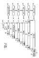
- FIG. 1shows a prior art framing sequence for user data in accordance with an 802.11-compliant WLAN.
- application layer 150transmission control protocol (TCP) layer 151 , Internet protocol (IP) layer 152 , logical link control (LLC) layer 153 (a sub-layer in the data link layer), medium access control (MAC) layer 154 (also a sub-layer in the data link layer), and physical (PHY) layer 155 (the physical layer).
- User data 101is provided to application layer 150 , which generates application data 102 by appending application-layer header 110 .
- Application data 102is provided to TCP layer 151 , which appends TCP header 111 to application data 102 to form TCP segment 103 .
- IP layer 152appends IP header 112 to TCP segment 103 to form IP frame 104 .
- IP frame 104might be a typical TCP/IP packet that is commonly employed in many data networking applications including some that are not necessarily 802.11-compliant.
- LLC layer 153provides a uniform interface between MAC layer 154 and higher layers, providing transparency of the type of WLAN used to transport the TCP/IP packet. LLC layer 153 appends this interface information as LLC header 113 to IP frame 104 to form LLC frame 105 .
- the physical deviceis a radio and the physical communication medium is free space.
- a MAC device and a PHY-layer signaling control deviceensure two network stations are communicating with the correct frame format and protocol.
- the IEEE 802.11 standard for WLANsdefines the communication protocol between two (or more) peer PHY devices as well as between the associated peer MAC devices.
- each packet frame transferred between the MAC device and the PHY devicehas a PHY header, a MAC header, MAC data, and error checking fields.
- a typical format for the MAC-layer frame of 802.11-compliant WLAN systemsappends MAC header 114 and frame check sequence (FCS) 115 to LLC frame 105 to form MAC frame 106 .
- FCSframe check sequence
- MAC header 114includes frame control, duration identification (ID), source (i.e., MAC layer) and destination address, and data sequence control (number) fields.
- the data sequence control fieldprovides sequence-numbering information that allows a receiver to reconstruct the data sequence order since the user data is a portion of a larger user data steam.
- PHY layer 155forms a physical-layer packet frame 107 by appending PHY header 118 to MAC frame 106 .
- PHY header 118includes preamble 116 and physical-layer convergence protocol (PLCP) header 117 .
- PLCP header 117identifies, for example, the data rate and length of PHY layer 155 , and preamble 116 might be used by a receiving device to i) detect/synchronize to the incoming frame and ii) estimate the channel characteristics between the transmitter and receiver.
- every MAC-layer frameis acknowledged with an ACK message (or ACK frame) that is sent a short interframe space (SIFS) period after the initial physical-layer frame is sent.
- SIFSshort interframe space
- some alternative acknowledgment methodsare specified, such as“No-ACK” in which no acknowledgment message is sent at all.
- Other possible methodsinclude variations of Block-ACK, where multiple data frames can be acknowledged in one Block-ACK message, which Block-ACK message is sent either immediately after a Block-ACK request (immediate Block-ACK) or after a separate contention period (delayed Block-ACK).
- each transmitted PHY-layer packet framecontains exactly one MAC frame.
- MAC framesmight be control or management frames, such as probe request or acknowledgment frames.
- Other MAC framesare data frames that contain exactly one packet of higher-layer user data.
- the MAC header and FCS fieldare included in the packet overhead.
- IEEE 802.11The efficiency of the IEEE 802.11 protocol degrades when higher physical-layer data rates are used. This is caused by several sources of overhead, both on the PHY-layer and MAC-layer levels, such as preamble, inter-frame space (IFS) timing, and header information, and also acknowledgment packets. IEEE 802.11 proposes some methods to improve efficiency, such as burst packet transmission and Block-ACK messaging, but these methods do not enable efficient use of PHY-layer rates of 162 Mbit/s or higher.
- IFSinter-frame space
- PHY-layer frame overheadis introduced by the PHY-frame preamble and by the PLCP header, which are both of a constant size for each MAC data frame.
- PHY-layer frame overheadis generally constant in time rather than in size (i.e., number of bytes)
- PHY layer frame overheaddoes not scale with higher data bit rates. Reducing the number of PHY frames for a given amount of transmitted user data can result in a significant improvement in efficiency.
- the PHY-layer overheadis included in every transmitted MAC frame, including those MAC frames not directly related to user data transfer (e.g., probe requests, RTS/CTS and Acknowledgment frames), reducing the number of separately transmitted MAC frames improves efficiency. Reducing the number of PHY frames also reduces the MAC contention overhead.
- a packet networkemploys frame aggregation to reduce the number of physical-layer frames employed to transfer a given amount of user data.
- the packet networkuses physical (PHY) and medium access control (MAC) layers of a wireless local area network (WLAN) operating in accordance with one or more IEEE 802.11 standards.
- Frame aggregationcombines several separate higher-layer frames with data, such as user or management/control data, into one PHY-layer frame, thus increasing the amount of user data per PHY-layer frame transmitted.
- Frame aggregationimproves the efficiency by reducing both PHY-layer overhead (e.g., preambles and PLCP header overhead) and MAC overhead (e.g., contention overhead).
- PHY-layer overheade.g., preambles and PLCP header overhead
- MAC overheade.g., contention overhead
- a frame of aggregated datais generated by (a) associating one or more user data frames into aggregated user data in accordance with a first layer; (b) generating, at an aggregation layer, one or more sub-frames from the aggregated user data by appending at least one header to the aggregated data, each sub-frame having a format in accordance with a second layer; and (c) forming an aggregated frame from the one or more sub-frames in accordance with a third layer.
- a frame of aggregated datais generated by (a) associating one or more user data frames into aggregated user data based on one of a plurality of aggregation formats; (b) generating, at an aggregation layer, one or more sub-frames from the aggregated user data by adding at least one header to the aggregated data; and (c) forming an aggregated frame from the one or more sub-frames.
- FIG. 1shows a prior art framing sequence for user data in accordance with an 802.11 wireless local area network (WLAN) standard;
- WLANwireless local area network
- FIG. 2shows frame aggregation above a medium access control (MAC) layer in accordance with a first exemplary embodiment
- FIG. 3shows frame aggregation below the MAC layer in accordance with a second exemplary embodiment
- FIG. 4shows frame aggregation below the MAC layer in accordance with an alternative to the second exemplary embodiment
- FIG. 5shows frame aggregation within the MAC layer in accordance with a third exemplary embodiment
- FIG. 6illustrates maximum throughput versus number of frames in aggregate for a 54-Mbit/s physical-(PHY-) layer data rate
- FIG. 7illustrates maximum throughput versus number of frames in aggregate for a 216-Mbits/s PHY-layer data rate
- FIG. 8illustrates maximum throughput versus number of frames in aggregate for a 324-Mbits/s PHY-layer data rate
- FIG. 9illustrates maximum throughput for various aggregation methods for a basic service set (BSS) simulated with three stations (STAs) operating with a 324-Mbit/s PHY layer data rate;
- BSSbasic service set
- STAsstations
- FIG. 10illustrates maximum throughput for various aggregation methods for a BSS simulated with three STAs operating with 324-, 216-, and 108-Mbit/s PHY layer data rates, respectively;
- FIG. 11illustrates maximum throughput for various aggregation methods for a BSS simulated with three STAs operating with a 324 Mbit/s PHY layer data rate, three STAs operating with a 216 Mbit/s PHY layer data rate, and three STAs operating with a 108 Mbit/s PHY layer data rate;
- FIG. 12illustrates maximum throughput for various aggregation methods for a BSS simulated as shown in FIG. 11 but with three connections per STA;
- FIG. 13shows an exemplary aggregated frame format in accordance with the described embodiments
- FIG. 14shows the MAC header format as employed by the exemplary aggregated frame descriptor of FIG. 13 ;
- FIG. 15shows an exemplary format of the MAC-layer length fields of FIG. 13 ;
- FIG. 16shows an exemplary method of reception where the receiving device supports frame aggregation
- FIG. 17shows an exemplary method of processing descriptor fields at step 1611 of FIG. 16 .
- frame aggregationreduces the number of, for example, physical-layer frames employed to transfer a given amount of user data.
- the exemplary embodiments described hereinrelate to a system operating in accordance with one or more IEEE 802.11 standards, which standards define the physical (PHY) and medium access control (MAC) layers of a wireless local area network (WLAN).
- IEEE 802.11 standardswhich standards define the physical (PHY) and medium access control (MAC) layers of a wireless local area network (WLAN).
- PHYphysical
- MACmedium access control
- WLANwireless local area network
- higher layerssuch as logical link control (LLC), Internet Protocol (IP), and transmission control protocol/user datagram protocol (TCP/UDP) layers, might be outside of the control of a lower-layer (e.g., 802.11) standard.
- LLClogical link control
- IPInternet Protocol
- TCP/UDPtransmission control protocol/user datagram protocol
- exemplary embodiments of the present inventionemploy frame aggregation to combine several separate higher-layer frames with user data into one PHY-level frame, thus increasing the amount of user data per PHY frame transmitted.
- Frame aggregationimproves the efficiency by reducing both PHY overhead (e.g., preambles and PLCP header overhead) and MAC overhead (e.g., contention overhead).
- PHY overheade.g., preambles and PLCP header overhead
- MAC overheade.g., contention overhead
- framesmight be aggregated for: A) frames having the same destination address and the same PHY-layer data rate, B) frames having one or more destination addresses and the same PHY-layer data rate, and C) frames having one or more destination addresses with each frame having one of several possible PHY-layer data rates.
- Aggregating frames having the same destination address and the same PHY-layer data ratemight require little or no changes in prior art MAC-layer and PHY-layer operation, and might preferably be employed when many frames specify the same destination address.
- uplink communication (traffic) in a basic service set (BSS)might typically employ frame aggregation in accordance with Case A.
- Case BAggregating frames having different destination addresses and the same PHY layer data rate, termed herein “Case B”, might typically be employed for stations (STAs) or access points (APs) that transfer data for different destination STAs. However, since the frames are sent on one data rate, the different destination STAs will preferably experience similar channel conditions.
- a scheduling methodselects frames for aggregation and schedules transmission, which for some embodiments might include accounting for packets having differing transmit priorities.
- Cise CAggregating frames having one or more destination addresses with each frame having one of several possible PHY-layer data rates, termed herein as “Case C”, provides greater flexibility and typically exhibits higher efficiency of use of the radio medium than frame aggregation for Cases A and B. Higher efficiency of use of the radio medium occurs since as all frames might be sent on their optimum data rates at any given time.
- frame aggregationmight be logically located in relation to the PHY and MAC layers.
- frame aggregationmight occur above (i.e., before operations of) the MAC layer, such as between the LLC layer and the MAC layer.
- frame aggregationmight occur below the MAC layer, such as between the MAC layer and the PHY layer, or in the PHY layer.
- frame aggregationmight occur within the MAC layer itself.
- Frame aggregation above the MAC layerinvolves minor modification of the operation of the MAC and PHY layers and might be accomplished by, for example, updating software drivers currently existing in network equipment.
- An ‘intermediate layer’might be logically implemented in existing network equipment to perform frame aggregation, involving little or no change to the operation of the MAC layer and the LLC layer.
- LLC frames 201 ( 1 ) through 201 (N), N a positive integer, at LLC layer 210might be combined into dummy LLC frame 202 by intermediate aggregation layer 203 .
- Dummy LLC frame 202is passed to MAC layer 204 , which appends MAC header 205 and MAC-layer FCS 206 to form MAC frame 207 .
- PHY layer 208forms PHY packet 211 from MAC frame 207 by appending preamble 209 and PLCP header 210 .
- Frame aggregation below the MAC layerforms several MAC frames into a dummy MAC frame before it is packetized by the PHY layer.
- Frame aggregation below the MAC layerenables verification of each LLC frame independently of the other frames since each MAC frame has error-detection information, such as a frame checksum, in an error-control field, such as an FCS field, appended to the LLC frame.
- error-detection informationsuch as a frame checksum
- FCS fielderror-control field
- Current 802.11-compliant WLAN systemssupport error-detection on the MAC level, but not necessarily error correction. However, one skilled in the art might employ any one of a number of error correction methods known in the art, instead of simple error detection.
- FIG. 3shows frame aggregation below the MAC layer in accordance with a second exemplary embodiment of the present invention.
- Each LLC frame 301 ( n )is formed into MAC sub-frame 316 ( n ) by appending MAC header 303 ( n ) and MAC FCS 304 ( n ).
- MAC sub-frames 316 ( 1 ) through 316 (M)are combined into dummy MAC frame 306 .
- Intermediate aggregation layer 307then appends optional i) dummy header 308 and/or ii) forward error correction/detection (FEC) field 309 to dummy MAC frame 306 to form aggregate MAC frame 310 .
- PHY layer 311forms PHY packet 312 from aggregate MAC frame 310 by appending preamble 313 and PLCP header 314 .
- Dummy header 308might be employed to indicate the number (e.g., M) and size (i.e., length) of MAC sub-frames 316 ( 1 ) through 316 (M) included in dummy MAC frame 306 .
- FEC field 309might be employed to correct bit errors at the receiver to increase the probability of correct reception of any of MAC sub-frames 316 ( 1 ) through 316 (M).
- multiple FEC fieldsmight be employed, either appended at one end of dummy MAC frame 306 or within each of MAC frames 316 ( 1 ) through 316 (M).
- a modified acknowledgment methode.g., delayed-ACK message exchange
- a modified acknowledgment methode.g., delayed-ACK message exchange
- FIG. 4shows frame aggregation within the PHY layer in accordance with an alternative to the second exemplary embodiment of the present invention.
- LLC frames 401 ( 1 ) through 401 (M) of LLC layer 402are passed to MAC layer 405 .
- MAC layer 405appends MAC header 403 ( n ) and MAC FCS 404 ( n ) to LLC frame 401 ( n ) to form MAC sub-frame 406 ( n ).
- MAC sub-frames 406 ( 1 ) through 406 (M)are then passed to PHY layer 407 .
- PHY layer 407appends PCLP header 409 ( n ) to each corresponding MAC sub-frame 406 ( n ) to form PHY sub-frame 410 ( n ).
- PHY sub-frames 410 ( 1 ) through 410 (M)are concatenated and preamble 408 is appended to the concatenated PHY sub-frames to form PHY packet 411 .
- multiple PHY framesare concatenated without duplicating the preamble, allowing transmission of separate MAC frames with different data rates and receiving each MAC frame independently.
- the included MAC framesmight be ordered in accordance with increasing data rate so that STAs having relatively poor channel conditions can correctly receive the lower data rates.
- Frame aggregation within the MAC layerintegrates frame aggregation of the present invention with existing MAC-layer operation, and allows relatively great flexibility. Frame aggregation within the MAC layer also allows for detection of the separate MAC frames. Frame aggregation within the MAC layer might include a MAC aggregation-frame format in accordance with the present invention. Such MAC aggregation-frame format imbeds several higher-layer data frames in a manner such that the higher-layer data frames can be received and decoded independently, allowing for transmission of the higher-layer data frames to different destination receivers. Furthermore, since the MAC layer controls the operation of the PHY layer, portions of the aggregated frame can be transmitted on different PHY data rates to allow each frame to be sent at its desired data rate.
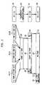
- FIG. 5shows frame aggregation within the MAC layer in accordance with a third exemplary embodiment of the present invention.
- LLC layer 502generates LLC frames 501 ( 1 ) through 501 (N), which are passed to MAC layer 503 .
- MAC layer 503comprises two operations: a first operation generates MAC sub-frames 506 ( 1 ) through 506 (N) from LLC frames 501 ( 1 ) through 501 (N), and a second operation generates MAC frame 507 from MAC sub-frames 506 ( 1 ) through 506 (N).
- MAC sub-frame 506 ( n )is generated by appending corresponding MAC header 504 ( n ) and MAC FCS 505 ( n ), in accordance with one or more IEEE 802.11 standards.
- MAC frame 507might be formed by grouping MAC sub-frames 506 ( 1 ) through 506 (N) according to data rate, and then prepending MAC descriptor 508 .
- MAC descriptor 508is a field that provides index information for the remaining portions of MAC frame 507 .
- MAC descriptor 508might also specify the position, length, and destination of one or more of MAC sub-frames 506 ( 1 ) through 506 (N) within MAC frame 507 .
- a receiverdetermines, by decoding MAC descriptor 508 , whether one or more of the included MAC sub-frames 506 ( 1 ) through 506 (N) are intended for the receiver.
- a receivermight employ this information to suspend listening mode when no MAC sub-frames are expected, leading to more efficient operation (e.g., conserve available power).
- MAC sub-frames 506 ( 1 ) through 506 (N)are grouped by data rate and concatenated into MAC frame portions 509 , 510 , and 511 . As with the embodiment shown in FIG. 4 , MAC sub-frames 506 ( 1 ) through 506 (N) are ordered with increasing data rate so that receivers with bad channel conditions may correctly receive MAC sub-frames having lower data rates. Consequently, MAC descriptor 508 is preferably transmitted with the lowest included data rate. For FIG. 5 , data rate X ⁇ data rate Y ⁇ data rate Z.
- MAC frame 507is passed to PHY layer 512 which forms PHY packet 518 .
- PHY layer 512forms PHY packet 518 by grouping MAC descriptor 508 with MAC frame portion 509 to form PHY data rate X portion 515 .
- MAC frame portions 510 and 511are mapped directly to PHY data rate Y and Z portions 516 and 517 , respectively.
- PHY data rate X, Y, and Z portions 515 , 516 , and 517are concatenated and appended to preamble 513 and PLCP header 514 to generate PHY packet 518 .
- PLCP header 514is shown located at the front of MAC frame 518 (i.e., immediately after the preamble), while alternative embodiments might locate PLCP header fields in front of the part of the MAC sub-frame(s) that the PLCP header field describes, such as immediately before each of PHY data rate X, Y, and Z portions 515 , 516 , and 517 .
- Operation of the exemplary embodiments of FIGS. 2 through 5might be simulated via computer, and performance, measured as medium efficiency, of the exemplary embodiments illustrated for varying conditions.
- Medium efficiencyis illustrated in FIGS. 6 through 8 by comparison of maximum achievable throughput under relatively ideal conditions in a point-to-point link.
- Every exchange sequenceconsists of one aggregated frame followed by one regular ACK frame (not a Block-ACK); ii) all data frames that are included in one aggregated frame are sent on the same data rate (e.g., 54-, 216-, and 324-Mbit/s) and all data frames are 1500 bytes large; iii) the ACK frames are sent on 54 Mbit/s, with regular 802.11a preamble and PLCP header and timing (short interframe space (SIFS), distributed interframe space (DIFS) and slot time) equivalent to the values defined in 802.11a; iv) contention is chosen to be the ‘optimum’ value of one slot for every frame exchange; and v) there are no collisions and bit/packet errors.
- SIFSshort interframe space
- DIFSdistributed interframe space
- FIGS. 6 , 7 , and 8illustrate maximum throughput versus number of frames in aggregate for 54-Mbit/s, 216-Mbits/s, and 324-Mbits/s PHY-layer data rates, respectively.
- Each of FIGS. 6 , 7 , and 8illustrates maximum throughput for the embodiments shown in FIG. 3 (MAC-layer aggregation shown with solid diamonds), FIG. 4 (PHY-layer aggregation shown with solid squares), and FIG. 5 (MAC-layer aggregation with MAC (frame) descriptor shown with dotted triangles).
- the used aggregation formatrepresents a single destination frame aggregation of Case A.
- the simulationrepresents frame aggregation for multiple data rates of Case C, since all included MAC sub-frames are sent at their own data rate. In each of the FIGS. 6 through 8 only one data rate is actually used.
- the MAC-layer aggregation with frame descriptor of FIG. 5represents aggregation with only one data rate and with multiple destinations (that, therefore, necessarily use the same data rate) of Case B. In each of the simulations of FIGS. 6 through 8 , only one destination is used.
- the simulation results illustrated in FIGS. 6 , 7 , and 8indicate that maximum throughput increases when more higher-layer frames are combined in one aggregated frame. Also, maximum throughput is relatively low if only a few higher-layer frames can be aggregated, especially for higher PHY-layer data rates.
- An aggregation method that allows for aggregation of frames with different destination stationshas a higher possibility of reaching a desired throughput because it is more likely to have frames available for aggregation.
- Aggregation methods that allow different parts of the frame to be sent having different data ratesare more likely to reach high medium efficiency, because these methods allow the aggregated frames to be sent to stations with completely different channel conditions, again increasing the possibility of having a large number of frames available for aggregation.
- the achievable maximum throughputdepends on the number of frames that are available for aggregation.
- Frame aggregation with multiple-destination framesincreases the number of frames available for aggregation.
- an AP of a BSStypically transmits to multiple STAs, while an STA typically only transmits to one or two APs. Consequently, this type of frame aggregation with multiple destinations might typically be employed for an AP transmitting to STAs.
- uplink traffic from an STA to APsmight employ a relatively simple method of frame aggregation, allowing only frames with one destination (and as a result one PHY-layer data rate) to be aggregated in one frame.
- FIGS. 9 through 12illustrate maximum throughput for several different configurations in a BSS simulated with a number of active STAs.
- the STAsoperate in different channel condition regions so that the STAs operate with different data rates.
- the APtransmits data frames to each of the active STAs, with data frames of 1500 bytes.
- Each stationhas a number of downlink connections, and per connection the AP has a certain number of frames per exchange sequence.
- the data frames, as well as the MAC-layer acknowledgmentsare transmitted with a PHY-layer frame format similar to that of 802.11a, but with an extended preamble (+10 ⁇ s) and extended PLCP header (+4 ⁇ s).
- Each sequenceuses three back-off slots for its contention.
- Each stationreplies (uplink) with one TCP acknowledgment (60-byte size) per connection per sequence. Bit/packet errors and/or collisions are not considered.
- the data rate on which immediate ACK frames are sentis (1/2.25) times the data rate of the corresponding data frame. Block-ACK messages and Block-ACK request messages are sent at the same data rate as the corresponding data frame.
- FIGS. 9 through 12seven simulated and compared aggregation methods are as follows.
- a first methodemploys no aggregation (i.e., every PHY-layer packet frame contains one single MAC frame), in accordance with the current 802.11 standards.
- the methodemploys a standard immediate ACK message, sent an SIFS period after each data frame, for both uplink and downlink transmissions.
- a second methodemploys single destination aggregation with an aggregated immediate ACK message, which is an extended version of the standard immediate ACK message.
- the APcombines all data frames for a single station in one aggregated frame.
- the STAreplies after an SIFS period with an aggregated immediate ACK message.
- the uplink channel (TCP-ACKs)employs data frames without aggregation, and the AP replies with a standard immediate ACK message.
- the third methodemploys single-destination aggregation with Block-ACK messages in both uplink and downlink transmission directions.
- Block-ACK and Block-ACK request messagesare included in the aggregated frames in both uplink and downlink directions.
- the fourth methodemploys single PHY data rate aggregation, where the uplink uses aggregated immediate ACK messages, the downlink uses Block-ACK messages.
- the APcombines all data frames for STAs having the same PHY-layer data rate into one aggregate frame (with multiple destinations).
- the fifth methodemploys single-rate aggregation in a manner similar to that of the fourth method, but with delayed Block-ACK messages in both uplink and downlink transmission directions. In both directions, Block-ACK request and Block-ACK messages are included in the aggregated frames.
- the sixth methodemploys multi-rate aggregation, where the uplink channel uses aggregated immediate ACK messages and the downlink channel uses Block-ACK messages.
- the APcombines frames for all PHY-layer data rates into one aggregate frame using the format of FIG. 5 .
- An additional PLCP headeris included per data rate to allow for data-rate switching (PLCP headers are included only per rate, rather than per frame).
- the seventh methodemploys multi-rate aggregation similar to that of the sixth method, but with delayed Block-ACK messages in both uplink and downlink channels directions.
- FIG. 9shows simulation results for a BSS with three STAs that each operates with the same PHY-layer data rate of 324 Mbit/s for data frames and 144 Mbit/s for immediate ACK message frames.
- Each STAhas one TCP connection with three frames per connection per aggregated frame (i.e., the AP sends three frames to every station during every cycle).
- Each STAreplies with one TCP ACK message frame per cycle (i.e. one ACK per three downlink frames).
- FIG. 10shows simulation results for the configuration of FIG. 9 except that each STA operates with a different PHY-layer data rate.
- one STAoperates on 324 Mbit/s (ACK message rate of 144 Mbit/s)
- one STAoperates on 216 Mbit/s (ACK message rate of 96 Mbit/s)
- one STAoperates on 108 Mbit/s (ACK message rate of 48 Mbit/s).
- FIG. 11shows simulation results for the configuration of FIG. 10 , except that there are nine STAs with three STAs operating with each of the PHY-layer data rates.
- FIG. 12shows simulation results for the configuration of FIG. 11 , but each STA supports three connections so that the AP has nine frames per station per cycle.
- frame aggregationprovides moderate to significant improvement in system performance under varying channel conditions.
- an exemplary aggregation frame formatis now described, the aggregation frame format allowing for aggregation of multiple frames for multiple destinations. While the exemplary aggregation frame format is described with respect to frames having the same PHY layer data rate, one skilled in the art might extend the teachings herein to frame aggregation formats for multiple destinations and including multiple data rates, such as for the exemplary third embodiment shown in FIG. 5 .
- the exemplary aggregation frame format described hereinallows for interoperability, for example, for 802.11-compliant devices that co-exist in a network with devices that employ frame aggregation. Even though the PHY-layer data rates described herein are data rates higher than 54-Mbit/s, the exemplary aggregation frame format might also be used on lower rates (e.g., 802.11a or 802.11g standard data rates), and as such might be compatible with existing MAC-layer implementations.
- the exemplary aggregation frame formatallows all types of MAC frames to be aggregated into one PHY frame, including data frames for different destinations, (Block-) ACK frames, and management frames. Power-efficient operation might be achieved when the destination addresses of the MAC frames are all located at the start of a PHY frame (i.e., in close vicinity to the PLCP header). To reduce the total listening time by a receiving device (e.g., STA), the destination addresses are ordered such that the destination addresses for which the most frames are included are at the end of the frame.
- a receiving devicee.g., STA
- the number of fields in the aggregate frame that provide an offset into the aggregate frameis relatively small.
- the negative effects from a bit error or a packet errorare preferably not be increased by a larger number of included MAC sub-frames or a larger total length of the frame.
- FIG. 13shows an exemplary aggregated frame format for PHY-layer packet 1301 .
- Packet 1301comprises preamble 1302 , PLCP header 1303 , aggregate data unit (ADU) 1304 , tail field 1305 , and optional pad bits 1306 .
- Aggregate data unit (ADU) 1304might also be termed a PLCP service data unit (PSDU).
- PSDUPLCP service data unit
- the aggregated frame format of FIG. 13might be employed for PHY-layer packets generated in accordance with the third exemplary embodiment of FIG. 5 .
- Preamble 1302is a pattern employed for packet detection in accordance with, for example, the 802.11 standard.
- Preamble 1302might be employed for synchronization to determine radio gain and to establish clear channel assessment.
- Tail field 1305is a 6-bit pattern indicating the end of PHY-layer packet 1301 , which might be employed to reset a receiver's Viterbi decoder.
- Optional pad bits 1306might be employed to make the length of PHY-layer packet 1301 conform to a predetermined value for transmission.
- PLCP header 1303comprises signal field 1340 , service field 1341 , and optional reserved field 1342 .
- Signal field 1340includes rate field 1343 , optional reserved field 1344 , length field 1345 , parity field 1346 , and tail 1347 .
- Rate field 1343is employed to specify the rate at which the payload is transmitted.
- Reserved field 1344 in the signal field 1340might be employed to indicate use of an aggregated frame in addition to or separate from aggregated frame descriptor 1310 (described subsequently), but might be employed for other applications.
- Length field 1345specifies the length (in bits) of the ensuing payload.
- Parity field 1346contains an error correction/detection value (e.g., parity check value) employed to verify the bits of PLCP header 1303 .
- Tail field 1347indicates the end of signal field 1340 , and also might be employed to reset the receiver's Viterbi decoder.
- Service field 1341is a currently reserved field, and might be employed to reset a transmitter's scrambler in the 802.11 standard.
- Optional reserved field 1342is reserved for additional TGn information (TGn, or Task Group n, is a group whose members study and adopt specifications for 802.11 n systems), such as additional PLCP information and/or additional preamble structures.
- ADU 1304comprises aggregated frame descriptor 1310 and aggregated MAC sub-frames 1311 ( 1 ) through 1311 (N) and optional aggregate FCS 1312 .
- MAC sub-frame 1311 ( n )comprises MAC (frame) header 1314 ( n ) and MAC FCS 1316 ( n ) appended to MAC data 1315 ( n ), where MAC data 1315 ( n ) might be the nth aggregated IP frame from the LLC layer.
- MAC header 1314 ( n ) and MAC FCS 1316 ( n )might be MAC header and MAC frame checksum generated in accordance with one or more 802.11 standards.
- MAC sub-frames 1311 ( 1 ) through 1311 (N)might be arranged in ascending order of PHY-layer data rate or in groups corresponding to selected data rates, and data-rate groups themselves might be ordered in ascending order of PHY data rate.
- Aggregated frame descriptor 1310comprises MAC (aggregated frame) header 1317 , frame number field 1318 , (aggregated frame) FCS 1319 , and descriptors 1320 ( 1 ) through 1320 (N). Aggregated frame descriptor 1310 is typically located at the front of ADU 1304 and indicates, via MAC header 1317 , that PHY-layer packet 1301 is an aggregated frame.
- MAC header 1317comprises frame control field 1330 , duration 1331 , address field 1 (ADDR 1 ) 1332 , address field 2 (ADDR 2 ) 1333 , address field 3 (ADDR 3 ) 1334 , and sequence control field 1335 .
- FIG. 14shows MAC header 1317 as employed by the exemplary aggregated frame format of FIG. 13 .
- frame control field 1330comprises protocol version field 1401 , type field 1402 , subtype field 1403 , ToDS field 1404 , FromDS field 1405 , MoreFrag field 1406 , Retry field 1407 , Pwr Mgt field 1408 , More Data field 1409 , WEP field 1410 , and Ordr field 1411 .
- Protocol version field 1401is 2 bits in length and indicates the version of the 802.11 standard employed for PHY-layer packet 1301 .
- Type field 1402 and subtype field 1403are 2 and 4 bits in length, respectively, and are employed to specify the type of aggregate frame 1304 .
- Such indicationmight be implemented as either a new value for the protocol version (e.g., 01) or as a new frame (sub-) type (e.g., type 00 (indicates management frame) with subtype 1111 (indicates aggregated frame descriptor) or type 11 with subtype 0000).
- such indicationmight be implemented as an existing protocol version and frame type, but with a special destination address (e.g., a multi-cast address could be used or the destination address of the frame descriptor is set to the address of the originator of the frame.
- ToDS field 1404 and FromDS field 1405indicate communication with a distribution system (DS).
- More Frag field 1406indicates a following fragment of the current ADU 1304 and is set to 0 in the preferred embodiment.
- Retry field 1407indicates a re-transmission and is set to 0 in the preferred embodiment.
- PwrMgt (Power Management) field 1408indicates if a STA is in power save mode (set to 1) or active mode (set to 0).
- More Data field 1409is set to 1 if any ADUs are buffered for that station.
- Wired equivalent privacy (WEP) field 1410is set to 1 if the information in the frame body was processed with the WEP algorithm specified in the 802.11 standard.
- Ordr (Order) field 1411is set to 1 if the frames must be strictly ordered to maintain the transmitted sequence that is passed to higher levels.
- duration field 1331is 2 bytes in length and contains the duration value for each field, the NAV setting, and the associated identity of the transmitting station.
- Address fields ADDR 1 1332 , ADDR 2 1333 , and ADDR 3 1334are each 6 bytes in length and identify the BSS, the destination address, the source address, and the receiver and transmitter addresses.
- Sequence control field 1335is 2 bytes in length and is split into 2 sub-fields (not shown in FIG. 13 ): fragment number and sequence number. The fragment number is 4 bits in length and indicates how many fragments the ADU is broken into. The sequence number field is 12 bits in length and indicates the sequence number of the ADU.
- Sequence control field 1335is restricted in accordance with the exemplary aggregated frame format and both the sequence and fragment number fields are set to 0.
- Number field 1318identifies the number N of MAC sub-frames 1311 ( 1 ) through 1311 (N) inside the aggregate frame, and the value of FCS field 1319 is a checksum value for the aggregated frame descriptor 1310 (e.g., the checksum over the first 24+2 bytes).
- FCS field 1319follows descriptor fields 1320 ( 1 ) through 1320 (N), each for an associated one of MAC sub-frames 1311 ( 1 ) through 1311 (N).
- Descriptor field 1320 ( n )contains destination MAC (Dest Addr) field 1336 ( n ) identifying the receiving device for which MAC sub-frame 1311 ( n ) is intended, start of frame (start frm) field 1337 which identifies the start position in ADU 1304 of MAC sub-frame 1311 ( n ), length of frame (length frm) field 1338 ( n ) which identifies the length of MAC sub-frame 1311 ( n ), and FCS field 1339 ( n ) which is a CRC value for descriptor field 1320 ( n ).
- Length field 1501 of 12 bitsindicates the length of a MAC sub-frame
- reserved (rsvd) field 1502comprises four bit positions reserved for future use. Since each descriptor field and each MAC sub-frame has its own FCS field, the possibility of MAC packet errors is not related to the number of aggregated frames.
- MAC sub-frame 1311 ( n )comprises MAC header 1314 ( n ), MAC data 1315 ( n ), and MAC FCS 1316 ( n ).
- MAC header 1314 ( n )might be a MAC header in accordance with an 802.11 standard without frame aggregation except the value of the duration field (not shown in FIG. 13 ) is set to the same value as that of duration field 1331 of aggregated frame descriptor 1310 .
- the Quality of Service (QoS) header extensionsmay be restricted (e.g., request for immediate ACK is not allowed).
- MAC data 1315 ( n )is the payload of MAC sub-frame 1311 ( n ), which may be an IP packet or LLC frame
- MAC FCS 1316 ( n )is a CRC value calculated over MAC header 1314 ( n ) and MAC data 1315 ( n ) of MAC sub-frame 1311 ( n ).
- the optional aggregate FCS field 1312contains a checksum value for entire ADU 1304 .
- the optional aggregate FCS field 1312might be included if backward-compatibility is required.
- the optional aggregate FCS field 1312might be used by devices that do not support the aggregated format to detect, and possibly correct, errors in the incoming ADU. Devices that do support the aggregated frame format shall discard the aggregate FCS field.
- a sending devicee.g., the STA or AP transmits the PHY-layer packet through the wireless medium, where the PHY-layer packet is detected by a receiving device (e.g., the AP or STA). Since i) the receiving device may or may not support an embodiment of frame aggregation, ii) the receiving device may or may not be the intended destination, and iii) the received PHY layer packet might contain one or more errors, the receiving device might perform one or more of the following operations upon detection of the packet having the aggregated frame format.
- FIG. 16shows an exemplary method of reception where the receiving device supports frame aggregation.
- the receiving devicei) detects the preamble, ii) decodes the PLCP header, and iii) determines the aggregated frame descriptor's frame control field indicates a frame aggregation type.
- the source address (Addr 2 ) and the duration field's valueare stored for later use. For some embodiments, the sequence number of the aggregate frame descriptor might also be discarded at step 1602 .
- a testcompares the value of BSSID in Addr 3 field to that of the receiving device.
- step 1604a test verifies the FCS field of the first part of the aggregated frame against the CRC of the frame. If the test of step 1604 verifies the FCS field, then, at step 1605 , the value of NAV (Network Allocation Vector) is set to the value of the duration field and the method advances to step 1606 . If the test of step 1604 does not verify the FCS field, then, at step 1609 , the extended interframe space (EIFS) is set and the method advances to step 1606 . At step 1606 , the rest of the aggregated frame is discarded.
- NAVNetwork Allocation Vector
- step 1603determines that the value of BSSID in Addr 3 field does match that of the receiving device, then, at step 1607 , the two bytes of the frame body are used to retrieve the number of destination addresses in the frame descriptor.
- step 1608a test verifies the FCS field of the first part of the aggregated frame against the CRC of the frame. If the test of step 1608 does not verify the FCS field of the first part of the aggregated frame descriptor, then, at step 1609 , the EIFS is set. At step 1606 , the rest of the aggregated frame is discarded. If the test of step 1607 does verify the FCS field of the first part of the aggregated frame descriptor, then at step 1610 , the NAV is set to the stored value of the duration field.
- the independent (MAC) descriptor fieldsare processed, one by one, in a manner described subsequently with respect to FIG. 17 .
- the MAC sub-framesare checked for errors by verification of the corresponding FCS fields, and the MAC sub-frames are processed for error detection/correction, if necessary.
- a receiving devicedetects errors during reception of a packet having an aggregated frame format, several different operations may occur. If an error is detected within the preamble or within the PLCP header, then the entire aggregated frame might be discarded. If one or more bit errors occur within a first part of the frame descriptor, then the entire aggregated frame might be discarded.
- a testdetermines whether the receiving device is the destination of at least one of the frames in the aggregated frame from the detected destination addresses in the aggregate frame descriptor. If the test of step 1612 determines that the receiving device is not an intended destination, then the method advances to step 1606 .
- the receiving devicemay, after step 1606 , enter a form of power saving mode during the remainder of the ongoing transmission (e.g. not detect and decode the incoming MAC sub-frames).
- step 1612determines that the receiving device is an intended destination, then, at step 1613 , the receiving device stores the starting byte and length of each of the MAC sub-frames.
- the first sub-frame locationis retrieved.
- the MAC sub-frame at the sub-frame locationis retrieved and the method begins decoding the MAC sub-frames. For example, if the first and second MAC sub-frames are sent to this receiving device, the receiving device waits until the end of the frame descriptor (i.e., the end of the last descriptor field) and starts decoding the first frame.
- the location of the first byte of this MAC sub-framemight also be indicated by the Start field of its associated descriptor field, as described previously with respect to FIGS. 13 and 14 for an exemplary aggregated frame format.
- a testverifies whether the FCS of the MAC sub-frame is correct. If the test of step 1616 determines that the FCS of the MAC sub-frame is correct, then, at step 1617 , the MAC sub-frame data (payload or LLC frame) is passed to the LLC layer. If the test of step 1616 determines that the FCS of the MAC sub-frame is not correct (i.e., incorrect by failing the CRC check), then, at step 1618 , the MAC sub-frame is discarded. At step 1619 , a test by the receiving device determines whether another MAC sub-frame is available for processing.
- step 1619determines that another MAC sub-frame is available. If the test of step 1619 determines that another MAC sub-frame is available, then, at step 1620 , the receiving device employs the associated start field from the MAC descriptor of the next MAC sub-frame to find the location of that next MAC sub-frame in the packet for retrieval. From step 1620 , the method returns to step 1615 .
- step 1619determines that no further MAC sub-frames are available, then, at step 1621 , the method terminates since the last MAC sub-frame intended for the receiving device has been processed.
- the receiving devicemay decide to enter some form of power saving mode during the remainder of the ongoing transmission (e.g. not detect and decode the remaining incoming MAC sub-frames).
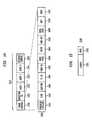
- FIG. 17is an exemplary method of processing descriptor fields at step 1611 of FIG. 16 .
- the independent (MAC) descriptor fieldsare processed, one by one.
- the first descriptor fieldis retrieved.
- a testverifies the sub-frame's FCS field (e.g., FCS field 1339 ( n )) against the CRC over the retrieved descriptor.
- a receiving deviceWhen a receiving device detects errors during reception of a packet having an aggregated frame format, several different operations may occur. If an error is detected within the preamble or within the PLCP header, then the entire aggregated frame might be discarded. If one or more bit errors occur within a first part of the frame descriptor (i.e., in the header, the 2-byte ‘Number-of-frames’ field or the first FCS field of the frame descriptor), the entire aggregated frame might be discarded. If an error occurs within an independent descriptor fields, then that descriptor might be discarded. If an error occurs within a MAC sub-frame, then that sub-frame might be discarded.
- step 1702If the test of step 1702 verifies the sub-frame FCS field is correct, then, at step 1703 , the information within the descriptor (e.g., destination address and length of sub-frame) is valid for use by the receiving device. If the test of step 1702 does not verify the FCS as correct, then, at step 1704 , the contents of the descriptor fields might be discarded. The associated sub-frame need not necessarily be discarded, as the receiving device may still receive that sub-frame without errors. From steps 1703 and 1704 , the method advances to step 1705 .
- the information within the descriptore.g., destination address and length of sub-frame
- a testdetermines whether the last descriptor field has been processed. If the test of step 1705 determines that the last descriptor field has not been processed, then, at step 1706 , the next descriptor field is retrieved and the method returns to step 1702 . If the test of step 1705 determines that the last descriptor field has been processed, then the method advances to step 1612 of FIG. 16 .
- an AP or STA devicereceives a packet with frame format conforming to frame aggregation in accordance with an embodiment of the present invention, but the AP or STA device does not support frame aggregation, then the receiving device might discard the frame. If, for example, the receiving device detects the preamble and decodes the PLCP header without errors, then at the start of the MAC frame the receiving device detects the frame descriptor. The receiving device determines that it does not support this packet frame type (either from the protocol version or the (sub-) type fields). Depending on the implementation, the receiving device may read the duration field and set the receiver's Network Allocation Vector (NAV) value accordingly (if the receiver validates the FCS-field value).
- NAVNetwork Allocation Vector
- the NAVis part of a clear channel assessment method and is employed to implement virtual channel assessment.
- Virtual channel assignmentallows a device to claim that the wireless medium is occupied, even when it is actually not (e.g., in between transmissions), helping to reduce the number and effect of collisions.
- the present inventioncan be embodied in the form of methods and apparatuses for practicing those methods.
- the present inventioncan also be embodied in the form of program code embodied in tangible media, such as floppy diskettes, CD-ROMs, hard drives, or any other machine-readable storage medium, wherein, when the program code is loaded into and executed by a machine, such as a computer, the machine becomes an apparatus for practicing the invention.
- the present inventioncan also be embodied in the form of program code, for example, whether stored in a storage medium, loaded into and/or executed by a machine, or transmitted over some transmission medium, such as over electrical wiring or cabling, through fiber optics, or via electromagnetic radiation, wherein, when the program code is loaded into and executed by a machine, such as a computer, the machine becomes an apparatus for practicing the invention.
- program codeWhen implemented on a general purpose processor, the program code segments combine with the processor to provide a unique device that operates analogously to specific logic circuits.
Landscapes
- Engineering & Computer Science (AREA)
- Computer Security & Cryptography (AREA)
- Computer Networks & Wireless Communication (AREA)
- Signal Processing (AREA)
- Computing Systems (AREA)
- Mobile Radio Communication Systems (AREA)
- Small-Scale Networks (AREA)
- Communication Control (AREA)
- Data Exchanges In Wide-Area Networks (AREA)
Abstract
Description
Claims (26)
Priority Applications (9)
| Application Number | Priority Date | Filing Date | Title |
|---|---|---|---|
| US10/955,943US7489688B2 (en) | 2003-12-23 | 2004-09-30 | Frame aggregation |
| EP04257846AEP1548990A1 (en) | 2003-12-23 | 2004-12-16 | Aggregated frame, generated above, within or below a MAC layer or in a physical layer |
| EP06077222.5AEP1775885B1 (en) | 2003-12-23 | 2004-12-16 | Aggregated frame, generated above, within or below a MAC layer or in a physical layer |
| EP11185191.1AEP2408175B1 (en) | 2003-12-23 | 2004-12-16 | Frame aggregation |
| JP2004366959AJP4917750B2 (en) | 2003-12-23 | 2004-12-20 | Frame aggregation |
| KR1020040111141AKR101093084B1 (en) | 2003-12-23 | 2004-12-23 | Set of frames |
| JP2006298599AJP5177995B2 (en) | 2003-12-23 | 2006-11-02 | Frame aggregation |
| KR1020060110547AKR101154829B1 (en) | 2003-12-23 | 2006-11-09 | A method of generating an aggregate frame, a method of processing a packet |
| US12/367,224US8396064B2 (en) | 2003-12-23 | 2009-02-06 | Frame aggregation |
Applications Claiming Priority (3)
| Application Number | Priority Date | Filing Date | Title |
|---|---|---|---|
| US53232503P | 2003-12-23 | 2003-12-23 | |
| US10/746,153US7586948B2 (en) | 2003-12-24 | 2003-12-24 | Packet sub-frame structure for selective acknowledgment |
| US10/955,943US7489688B2 (en) | 2003-12-23 | 2004-09-30 | Frame aggregation |
Related Parent Applications (1)
| Application Number | Title | Priority Date | Filing Date |
|---|---|---|---|
| US10/746,153Continuation-In-PartUS7586948B2 (en) | 2003-12-23 | 2003-12-24 | Packet sub-frame structure for selective acknowledgment |
Related Child Applications (1)
| Application Number | Title | Priority Date | Filing Date |
|---|---|---|---|
| US12/367,224ContinuationUS8396064B2 (en) | 2003-12-23 | 2009-02-06 | Frame aggregation |
Publications (2)
| Publication Number | Publication Date |
|---|---|
| US20050152358A1 US20050152358A1 (en) | 2005-07-14 |
| US7489688B2true US7489688B2 (en) | 2009-02-10 |
Family
ID=34556581
Family Applications (2)
| Application Number | Title | Priority Date | Filing Date |
|---|---|---|---|
| US10/955,943Active2025-12-05US7489688B2 (en) | 2003-12-23 | 2004-09-30 | Frame aggregation |
| US12/367,224Expired - Fee RelatedUS8396064B2 (en) | 2003-12-23 | 2009-02-06 | Frame aggregation |
Family Applications After (1)
| Application Number | Title | Priority Date | Filing Date |
|---|---|---|---|
| US12/367,224Expired - Fee RelatedUS8396064B2 (en) | 2003-12-23 | 2009-02-06 | Frame aggregation |
Country Status (4)
| Country | Link |
|---|---|
| US (2) | US7489688B2 (en) |
| EP (2) | EP1548990A1 (en) |
| JP (2) | JP4917750B2 (en) |
| KR (2) | KR101093084B1 (en) |
Cited By (22)
| Publication number | Priority date | Publication date | Assignee | Title |
|---|---|---|---|---|
| US20050220145A1 (en)* | 2004-04-02 | 2005-10-06 | Yasuyuki Nishibayashi | Communication apparatus, communication system, communication method, and communication control program |
| US20050265393A1 (en)* | 2004-06-01 | 2005-12-01 | Fischer Matthew J | Network time reservation cancellation |
| US20060153240A1 (en)* | 2005-01-12 | 2006-07-13 | Nec Corporation | Radio packet signal transmission system, radio packet signal transmission terminal and radio packet signal transmission method used in these |
| US20080095150A1 (en)* | 2006-10-20 | 2008-04-24 | D&S Consultants, Inc. | Method and system for mitigating traffic congestions in a communication network |
| US20090028087A1 (en)* | 2007-07-26 | 2009-01-29 | The Directv Group, Inc. | Method and system for communicating content having modified packet headers through a satellite |
| US20090031189A1 (en)* | 2007-07-26 | 2009-01-29 | The Directv Group, Inc. | Method and system for forming a formatted content stream and using a cyclic redundancy check |
| US20090122709A1 (en)* | 2007-11-08 | 2009-05-14 | Harris Corporation | Promiscuous monitoring using internet protocol enabled devices |
| US20090208207A1 (en)* | 2008-02-15 | 2009-08-20 | Alcatel-Lucent | System, method and computer readable medium for providing dual rate transmission on a gigabit passive optical network |
| US20090285192A1 (en)* | 2008-05-13 | 2009-11-19 | Youichirou Shiba | Wireless communication apparatus capable of performing aggregated transmission |
| US20090296612A1 (en)* | 2008-05-30 | 2009-12-03 | Motorola, Inc. | Method for aggregating frames in a wireless communication network |
| US20100103909A1 (en)* | 2008-10-24 | 2010-04-29 | Mitac Technology Corp. | Data packet, system and method for multiple nodes transmitting under ad-hoc network architecture |
| US20110038359A1 (en)* | 2007-04-25 | 2011-02-17 | Canon Kabushiki Kaisha | Communication apparatus, communication apparatus control method, and computer program for causing computer to execute the control method |
| CN102447530A (en)* | 2011-11-23 | 2012-05-09 | 西安电子科技大学 | Data frame aggregation method with fault-tolerant function |
| US8612517B1 (en) | 2012-01-30 | 2013-12-17 | Google Inc. | Social based aggregation of related media content |
| US20140089513A1 (en)* | 2012-09-25 | 2014-03-27 | Kabushiki Kaisha Toshiba | Wireless communication apparatus and method |
| US20150207740A1 (en)* | 2012-07-09 | 2015-07-23 | Alcatel Lucent | Methods and device for processing digital data frames and transport frames for reduction of transport bandwidth |
| US9143742B1 (en) | 2012-01-30 | 2015-09-22 | Google Inc. | Automated aggregation of related media content |
| US9159364B1 (en) | 2012-01-30 | 2015-10-13 | Google Inc. | Aggregation of related media content |
| US9923611B2 (en) | 2005-09-27 | 2018-03-20 | Qualcomm Incorporated | Maximum combining in broadcast OFDM systems based on multiple receive antennas |
| US10270890B2 (en) | 2015-07-13 | 2019-04-23 | Gainspan Corporation | Transmitting IP packets originating in a wireless station when the IP packets are destined for delivery to multiple destinations via an access point |
| US11464059B2 (en) | 2015-10-20 | 2022-10-04 | Nxp Usa, Inc. | Acknowledgment data unit for multiple uplink data units |
| US11503499B2 (en) | 2016-02-19 | 2022-11-15 | Nxp Usa, Inc. | Acknowledgement of transmissions in a wireless local area network |
Families Citing this family (102)
| Publication number | Priority date | Publication date | Assignee | Title |
|---|---|---|---|---|
| JP4005974B2 (en) | 2004-01-09 | 2007-11-14 | 株式会社東芝 | COMMUNICATION DEVICE, COMMUNICATION METHOD, AND COMMUNICATION SYSTEM |
| WO2005096752A2 (en)* | 2004-04-01 | 2005-10-20 | Devicescape Software, Inc. | Multi channel throughput enhancement |
| US7433329B2 (en)* | 2004-04-07 | 2008-10-07 | Cisco Technology, Inc. | Aggregation scheduler |
| KR20070020033A (en)* | 2004-05-13 | 2007-02-16 | 코닌클리케 필립스 일렉트로닉스 엔.브이. | Multiple receiver set (MRA) with different data rates for IEEE 802.11N |
| EP1751921A1 (en)* | 2004-05-13 | 2007-02-14 | Koninklijke Philips Electronics N.V. | Superframe protocol packet data unit format having multirate packet aggregation for wireless systems |
| KR100631271B1 (en) | 2004-08-07 | 2006-10-02 | 삼성전자주식회사 | Packet aggregation transmission method |
| JP4440037B2 (en) | 2004-08-11 | 2010-03-24 | 株式会社東芝 | Communication apparatus and communication method |
| EP1635496B1 (en)* | 2004-09-10 | 2018-09-05 | Samsung Electronics Co., Ltd. | Data communication method based on multi-receiver aggregation |
| KR100605979B1 (en) | 2004-09-10 | 2006-07-31 | 삼성전자주식회사 | Data communication method based on multiple receiver aggregation |
| US7474676B2 (en)* | 2004-09-10 | 2009-01-06 | Mitsubishi Electric Research Laboratories, Inc. | Frame aggregation in wireless communications networks |
| JP2006261935A (en)* | 2005-03-16 | 2006-09-28 | Nec Corp | Packet transmission method and device |
| US20070053354A1 (en)* | 2005-08-18 | 2007-03-08 | Interdigital Technology Corporation | Method and system for securing wireless transmission of an aggregated frame |
| KR20080074854A (en)* | 2005-09-12 | 2008-08-13 | 퀄컴 인코포레이티드 | High Speed Control Messaging Mechanism for Use in Wireless Network Communications |
| JP4841330B2 (en) | 2005-09-14 | 2011-12-21 | 三洋電機株式会社 | Radio apparatus and communication system |
| JP4943749B2 (en)* | 2005-09-16 | 2012-05-30 | 三洋電機株式会社 | Wireless device and communication system using the same |
| KR100857117B1 (en)* | 2005-10-05 | 2008-09-05 | 엘지전자 주식회사 | Method and apparatus for signal processing and encoding and decoding method, and apparatus therefor |
| US9521584B2 (en)* | 2005-10-17 | 2016-12-13 | Qualcomm Incorporated | Method and apparatus for managing data flow through a mesh network |
| KR100615139B1 (en) | 2005-10-18 | 2006-08-22 | 삼성전자주식회사 | Method and apparatus for allocating transmission period in wireless telecommunication system and therefor system |
| US9369246B2 (en) | 2005-12-30 | 2016-06-14 | Vtech Telecommunications Limited | System and method of enhancing WiFi real-time communications |
| US7697529B2 (en) | 2006-02-28 | 2010-04-13 | Cisco Technology, Inc. | Fabric channel control apparatus and method |
| DE102006025918B4 (en)* | 2006-06-02 | 2008-05-08 | Nokia Siemens Networks Gmbh & Co.Kg | Method and arrangement for transmitting signals in systems with point-to-multipoint connections |
| US20070286107A1 (en)* | 2006-06-12 | 2007-12-13 | Harkirat Singh | System and method for wireless communication of uncompressed video having multiple destination aggregation (MDA) |
| US8300563B2 (en)* | 2006-09-29 | 2012-10-30 | Intel Corporation | Aggregated transmission in WLAN systems with FEC MPDUs |
| WO2008070738A1 (en)* | 2006-12-05 | 2008-06-12 | Qualcomm Incorporated | Enhanced management frame aggregation in a wireless network system |
| US20080130538A1 (en)* | 2006-12-05 | 2008-06-05 | Qualcomm Incorporated | Enhanced management frame aggregation in a wireless network system |
| US7697533B2 (en)* | 2006-12-15 | 2010-04-13 | Mediatek Inc. | Communication device and method |
| US8081588B2 (en)* | 2006-12-28 | 2011-12-20 | Research In Motion Limited | Methods and apparatus for increasing data throughput by grouping data packets into maximum transmissible units |
| KR101082711B1 (en) | 2006-12-31 | 2011-11-15 | 콸콤 인코포레이티드 | Methods and apparatus for use in a communication system |
| EP2122883B1 (en)* | 2007-01-16 | 2018-03-14 | Koninklijke Philips N.V. | System and method for efficient transmission of multimedia and data |
| JP2008301333A (en)* | 2007-06-01 | 2008-12-11 | Fujitsu Ltd | Multiplex transmission method and apparatus |
| KR20080109617A (en)* | 2007-06-13 | 2008-12-17 | 한국전자통신연구원 | Apparatus and method of data transmission and reception using multi-path |
| JP2009021654A (en)* | 2007-07-10 | 2009-01-29 | Panasonic Corp | Wireless communication apparatus and communication load calculation method thereof |
| JP4957419B2 (en)* | 2007-07-10 | 2012-06-20 | ソニー株式会社 | Wireless communication apparatus, wireless communication system, wireless communication method, and program |
| US8386878B2 (en) | 2007-07-12 | 2013-02-26 | Samsung Electronics Co., Ltd. | Methods and apparatus to compute CRC for multiple code blocks |
| US20090092039A1 (en)* | 2007-10-03 | 2009-04-09 | Samsung Electronics Co., Ltd. | Method and system for formation and communication of information frames in wireless communication systems |
| US8681755B2 (en)* | 2007-10-30 | 2014-03-25 | Samsung Electronics Co., Ltd. | Method and apparatus for generating data frame in wireless personal area network |
| US20090150750A1 (en)* | 2007-12-05 | 2009-06-11 | Qualcomm Incorporated | Method and apparatus for harq encoding with low memory requirement |
| JP2009147786A (en)* | 2007-12-17 | 2009-07-02 | Nec Corp | Communication device, data frame transmission control method, and program |
| US8416803B1 (en)* | 2008-02-14 | 2013-04-09 | Wilocity, Ltd. | Low latency interconnect bus protocol |
| KR100899168B1 (en)* | 2008-02-20 | 2009-05-27 | 주식회사 인켈 | Variable Multiframe Formation Method for Communication |
| US8572240B2 (en)* | 2008-03-31 | 2013-10-29 | Panasonic Corporation | Monitoring system |
| US8126014B2 (en)* | 2008-04-09 | 2012-02-28 | Qualcomm Incorporated | Methods and apparatus for improved decoding of hybrid automatic repeat request transmissions |
| US8331272B2 (en)* | 2008-04-29 | 2012-12-11 | Telefonaktiebolaget L M Ericsson (Publ) | Aggregation of resources over multiple frames in a TDD communication system |
| US8897209B2 (en)* | 2008-07-15 | 2014-11-25 | Qualcomm Incorporated | Systems and methods for parallel communication with legacy WLAN receivers |
| US8464138B2 (en)* | 2008-08-20 | 2013-06-11 | Qualcomm Incorporated | Effective utilization of header space for error correction in aggregate frames |
| JP5374717B2 (en)* | 2008-08-21 | 2013-12-25 | 独立行政法人情報通信研究機構 | Sensor network system that realizes highly reliable control command transmission and reception and bandwidth efficiency |
| US8706878B1 (en) | 2008-08-21 | 2014-04-22 | United Services Automobile Association | Preferential loading in data centers |
| US9477615B1 (en) | 2008-08-26 | 2016-10-25 | Qualcomm Incorporated | Bi-directional low latency bus mode |
| KR101354130B1 (en) | 2008-12-22 | 2014-01-24 | 한국전자통신연구원 | Method for transmitting and receiving the frame in wireless LAN |
| US20100232356A1 (en)* | 2009-03-16 | 2010-09-16 | Qualcomm Incorporated | Layer two segmentation techniques for high data rate transmissions |
| US8498280B2 (en)* | 2009-03-27 | 2013-07-30 | Qualcomm Incorporated | Method and system for reducing header information in communication systems |
| US8135015B2 (en)* | 2009-03-27 | 2012-03-13 | Qualcomm Incorporated | System and method of transmitting and receiving data frames |
| US20100260114A1 (en)* | 2009-04-10 | 2010-10-14 | Qualcomm Incorporated | Acknowledgement resource allocation and scheduling for wlans |
| JP5316208B2 (en) | 2009-05-08 | 2013-10-16 | ソニー株式会社 | COMMUNICATION DEVICE AND COMMUNICATION METHOD, COMPUTER PROGRAM, AND COMMUNICATION SYSTEM |
| US8817698B2 (en) | 2009-10-18 | 2014-08-26 | Intel Corporation | Device, system and method of selectively aborting reception of wireless communication packets |
| US9268813B2 (en) | 2009-12-24 | 2016-02-23 | Samsung Electronics Co., Ltd. | Terminal device based on content name, and method for routing based on content name |
| US9264342B2 (en) | 2009-12-24 | 2016-02-16 | Samsung Electronics Co., Ltd. | Terminal device based on content name, and method for routing based on content name |
| KR101758909B1 (en) | 2010-02-18 | 2017-07-18 | 엘지전자 주식회사 | Method and apparatus of transmitting reception acknowledgement in wireless local area network |
| FR2957217A1 (en)* | 2010-03-08 | 2011-09-09 | France Telecom | METHODS OF TRANSMITTING AND RECEIVING DATA USING RADIO FREQUENCY CHANNEL PLURALITY, TRANSMISSION EQUIPMENT AND RECEIVER, CORRESPONDING SIGNAL AND COMPUTER PROGRAM |
| US8879580B2 (en)* | 2010-06-17 | 2014-11-04 | Texas Instruments Incorporated | Enhancing packet aggregation performance in coexisting wireless networks |
| US8700796B2 (en) | 2010-09-22 | 2014-04-15 | Qualcomm Incorporated | MAC data service enhancements |
| US20120243602A1 (en)* | 2010-09-23 | 2012-09-27 | Qualcomm Incorporated | Method and apparatus for pipelined slicing for wireless display |
| US8473821B2 (en) | 2010-11-09 | 2013-06-25 | Qualcomm, Incorporated | Packet-level erasure protection coding in aggregated packet transmissions |
| CN102684852A (en)* | 2011-03-31 | 2012-09-19 | 北京新岸线无线技术有限公司 | Method and device for frame acknowledgement |
| EP2712051B1 (en)* | 2011-05-13 | 2017-11-01 | Samsung Electronics Co., Ltd. | Transmitter and receiver in a wireless power transmitting system, and method for the transmitter and receiver to wirelessly transmit/receivetransceive power |
| US9515925B2 (en)* | 2011-05-19 | 2016-12-06 | Qualcomm Incorporated | Apparatus and methods for media access control header compression |
| US20120320772A1 (en)* | 2011-06-14 | 2012-12-20 | Qualcomm Incorporated | Communication devices for transmitting data based on available resources |
| US8929398B2 (en)* | 2011-06-20 | 2015-01-06 | Texas Instruments Incorporated | Data frame for PLC having destination address in the PHY header |
| US9125181B2 (en)* | 2011-08-23 | 2015-09-01 | Qualcomm Incorporated | Systems and methods for compressing headers |
| JP5403034B2 (en)* | 2011-11-02 | 2014-01-29 | 日本電気株式会社 | COMMUNICATION DEVICE, COMMUNICATION SYSTEM, AND COMMUNICATION METHOD |
| CN103209045A (en)* | 2012-01-12 | 2013-07-17 | 华为终端有限公司 | Data communication method, device and system |
| US8848559B2 (en)* | 2012-01-26 | 2014-09-30 | Qualcomm Incorporated | Methods and apparatuses for device discovery |
| US9860785B2 (en)* | 2012-05-11 | 2018-01-02 | Qualcomm, Incorporated | Apparatus and methods for control frame and management frame compression |
| US8982859B2 (en) | 2012-06-20 | 2015-03-17 | Intel Corporation | Wireless device and method of short MAC frame indication |
| US10178582B2 (en)* | 2012-08-06 | 2019-01-08 | Qualcomm Incorporated | Apparatus and methods for frame control design |
| JP6024318B2 (en) | 2012-09-10 | 2016-11-16 | 富士通株式会社 | Wireless LAN base station, wireless LAN terminal, and packet transfer method |
| CN103812606B (en)* | 2012-11-21 | 2018-07-17 | 优倍快网络公司 | Method and system for improving the efficiency of a wireless link |
| US9270792B2 (en) | 2012-11-21 | 2016-02-23 | Ubiquiti Networks, Inc. | Method and system for improving wireless link efficiency |
| US9398123B2 (en)* | 2013-05-03 | 2016-07-19 | Qualcomm Incorporated | Systems and methods for aggregation of physical protocol data units on a wireless network |
| CN104219031A (en)* | 2013-06-04 | 2014-12-17 | 中兴通讯股份有限公司 | MAC (media access control) frame aggregation method and device |
| US20150046775A1 (en)* | 2013-08-07 | 2015-02-12 | Broadcom Corporation | Encoding and Decoding Schemes to Achieve Standard Compliant Mean Time to False Packet Acceptance |
| US9166734B2 (en)* | 2013-08-14 | 2015-10-20 | National Cheng Kung University | Method and device for frame aggregation transmission of wireless network system |
| US20150071273A1 (en)* | 2013-09-11 | 2015-03-12 | Celeno Communications (Israel) Ltd. | Efficient transfer of tcp traffic over wlan |
| US9231732B2 (en)* | 2013-10-07 | 2016-01-05 | Texas Instruments Incorporated | Packet header protection for utility networks |
| US9439099B2 (en) | 2013-10-14 | 2016-09-06 | Netgear, Inc. | Systems and methods for simultaneously using multiple WLAN modules operating in different wireless bands |
| KR101727781B1 (en)* | 2013-10-14 | 2017-05-02 | 한국전자통신연구원 | Physical layer low energy communication method and apparatus |
| WO2015198158A2 (en)* | 2014-06-27 | 2015-12-30 | Techflux, Ltd. | Operating in power save mode |
| KR101586716B1 (en)* | 2015-01-05 | 2016-01-19 | 아주대학교산학협력단 | Communication Method and Apparatus using slot based channel |
| US20160286011A1 (en)* | 2015-03-26 | 2016-09-29 | Assaf Kasher | Techniques for communicating an end of packet indicator |
| US9973314B2 (en)* | 2015-04-06 | 2018-05-15 | Qualcomm Incorporated | Control frame aggregation frame |
| JP6434153B2 (en)* | 2015-08-06 | 2018-12-05 | 株式会社日立国際電気 | Shooting training system, wireless communication system, master station, and slave station |
| JP2017046325A (en)* | 2015-08-28 | 2017-03-02 | 株式会社東芝 | COMMUNICATION DEVICE, COMMUNICATION METHOD, AND PROGRAM |
| US10820207B2 (en)* | 2016-05-10 | 2020-10-27 | Mediatek Inc. | Backward compatible frame reuse by using predetermined masking sequence |
| CN107528667B (en)* | 2016-06-21 | 2020-09-11 | 大唐移动通信设备有限公司 | Method and device for transmitting frame data between near-end equipment and far-end equipment |
| US11368873B2 (en)* | 2017-12-15 | 2022-06-21 | Huawei Technologies Co., Ltd. | Method and system of packet aggregation |
| CN111679998B (en)* | 2020-06-03 | 2023-07-25 | 上海兆芯集成电路股份有限公司 | Multi-chip system and its data transmission method |
| EP3923516B1 (en)* | 2020-06-10 | 2024-02-28 | Mitsubishi Electric R&D Centre Europe B.V. | Message exchanges in "open platform communications unified architecture" |
| JP7683908B2 (en)* | 2021-02-01 | 2025-05-27 | Necソリューションイノベータ株式会社 | COMMUNICATION CONTROL DEVICE, COMMUNICATION CONTROL METHOD, PROGRAM, AND COMMUNICATION SYSTEM |
| US20230337295A1 (en)* | 2022-04-18 | 2023-10-19 | Apple Inc. | Methods for connection oriented data transfer for ultra-wideband systems and apparatuses |
| CN115225711A (en)* | 2022-06-01 | 2022-10-21 | 裕太微(上海)电子有限公司 | An Efficient Transmission Ethernet Device |
| WO2024172758A1 (en)* | 2023-02-17 | 2024-08-22 | Panasonic Intellectual Property Corporation Of America | Communication apparatus and communication method for multi-layer transmission |
| WO2025121969A1 (en)* | 2023-12-07 | 2025-06-12 | 엘지전자 주식회사 | Method and device for performing relay transmission in wireless lan system |
Citations (39)
| Publication number | Priority date | Publication date | Assignee | Title |
|---|---|---|---|---|
| US4727536A (en) | 1986-06-19 | 1988-02-23 | General Datacomm, Inc. | Variable control and data rates in highly efficient multiplexer |
| US5467342A (en) | 1994-01-12 | 1995-11-14 | Scientific-Atlanta, Inc. | Methods and apparatus for time stamp correction in an asynchronous transfer mode network |
| US5583859A (en) | 1994-08-30 | 1996-12-10 | Bell Communications Research, Inc. | Data labeling technique for high performance protocol processing |
| GB2315694A (en) | 1996-07-30 | 1998-02-11 | Tokyo Seimitsu Co Ltd | Wafer polishing machine |
| GB2315964A (en) | 1996-07-31 | 1998-02-11 | Nec Corp | Transmitting fixed length data blocks containing variable length sub-blocks |
| EP0912016A2 (en) | 1997-10-14 | 1999-04-28 | Lucent Technologies Inc. | Method for access control in a multiple access system for communications networks |
| WO1999063703A2 (en) | 1998-06-03 | 1999-12-09 | Nokia Networks Oy | Data transmission methods in a telecommunication system |
| US6041051A (en) | 1996-06-14 | 2000-03-21 | Lucent Technologies, Inc. | Method and apparatus enabling multiple access for multiple services and multiple transmission modes over a broadband communication network utilizing an adaptive digital access protocol |
| EP0987842A1 (en) | 1998-04-07 | 2000-03-22 | Matsushita Electric Industrial Co., Ltd. | Radio base station apparatus and radio communication method |
| JP2000295313A (en) | 1999-04-06 | 2000-10-20 | Nec Corp | Method and device for communication |
| US6236647B1 (en) | 1998-02-24 | 2001-05-22 | Tantivy Communications, Inc. | Dynamic frame size adjustment and selective reject on a multi-link channel to improve effective throughput and bit error rate |
| US20010024435A1 (en) | 1996-05-28 | 2001-09-27 | Microsoft Corporation | Multi-packet transport structure and method for sending network data over satellite network |
| US6317430B1 (en) | 1998-02-19 | 2001-11-13 | Lucent Technologies Inc. | ARQ protocol support for variable size transmission data unit sizes using a hierarchically structured sequence number approach |
| WO2002005453A2 (en) | 2000-07-11 | 2002-01-17 | Ensemble Communications, Inc. | Method and apparatus for bandwidth request/grant protocols in a wireless communication system |
| US20020093928A1 (en) | 2001-01-16 | 2002-07-18 | Motorola, Inc. | Slot format and acknowledgement method for a wireless communication system |
| US20020110148A1 (en)* | 2001-01-30 | 2002-08-15 | Hickman Graeme A. | Link aggregation control for network devices |
| US6452946B1 (en) | 1999-06-04 | 2002-09-17 | Siemens Information And Communications Network, Inc. | Apparatus and method for improving performance in master and slave communications systems |
| US20030086366A1 (en) | 2001-03-06 | 2003-05-08 | Branlund Dale A. | Adaptive communications methods for multiple user packet radio wireless networks |
| US20030128706A1 (en)* | 2001-06-14 | 2003-07-10 | Mark Barry Ding Ken | Extension of link aggregation protocols over the network |
| US6594278B1 (en) | 1998-05-01 | 2003-07-15 | Cisco Technology, Inc. | Apparatus for transmitting delay sensitive information over frame relay |
| US20030135640A1 (en) | 2002-01-14 | 2003-07-17 | Texas Instruments Incorporated | Method and system for group transmission and acknowledgment |
| US20030169769A1 (en) | 2002-03-08 | 2003-09-11 | Texas Instruments Incorporated | MAC extensions for smart antenna support |
| US20030171114A1 (en)* | 2002-03-05 | 2003-09-11 | Hastings David C. | Optimized wireless LAN solution for embedded systems |
| US6640248B1 (en) | 1998-07-10 | 2003-10-28 | Malibu Networks, Inc. | Application-aware, quality of service (QoS) sensitive, media access control (MAC) layer |
| US20040052273A1 (en)* | 2002-09-17 | 2004-03-18 | Jeyhan Karaoguz | System and method for providing a super channel in a multi-band multi-protocol hybrid wired/wireless network |
| WO2004039011A2 (en) | 2002-10-25 | 2004-05-06 | Qualcomm Incorporated | Mimo wlan system |
| US20040141460A1 (en) | 2003-01-16 | 2004-07-22 | Holtzman Jack M. | Margin control in a data communication system |
| US6775804B1 (en) | 2000-11-28 | 2004-08-10 | Nortel Networks Limited | Determining integrity of a packet |
| US20040180696A1 (en) | 1997-06-20 | 2004-09-16 | Tantivy Communications, Inc. | Dynamic frame size adjustment and selective reject on a multi-link channel to improve effective throughput and bit error rate |
| US20040240424A1 (en) | 2003-03-06 | 2004-12-02 | Mo-Han Fong | Reverse link enhancement for CDMA 2000 release D |
| US6859501B1 (en) | 1997-04-11 | 2005-02-22 | Deutschetelekom Ag | System for transmitting high-speed added-value services in terrestrial digital broadcasting |
| US20050053037A1 (en) | 2003-09-10 | 2005-03-10 | Boris Ginzburg | Method and device of adaptive control of data rate, fragmentation and request to send protection in wireless networks |
| US6877043B2 (en) | 2000-04-07 | 2005-04-05 | Broadcom Corporation | Method for distributing sets of collision resolution parameters in a frame-based communications network |
| US6928289B1 (en) | 1998-08-26 | 2005-08-09 | Samsung Electronics Co., Ltd. | Device and method for communicating packet voice data in mobile communication system |
| US20050286523A1 (en) | 2000-11-16 | 2005-12-29 | Microsoft Corporation | Robust, inferentially synchronized transmission of compressed transport-layer-protocol headers |
| US6987770B1 (en)* | 2000-08-04 | 2006-01-17 | Intellon Corporation | Frame forwarding in an adaptive network |
| US20070101020A1 (en) | 2005-10-28 | 2007-05-03 | Tzu-Ming Lin | Packet transmitting method of wireless network |
| US7231530B1 (en) | 2004-04-06 | 2007-06-12 | Cisco Technology, Inc. | System and method for saving power in a wireless network by reducing power to a wireless station for a time interval if a received packet fails an integrity check |
| US7298691B1 (en) | 2000-08-04 | 2007-11-20 | Intellon Corporation | Method and protocol to adapt each unique connection in a multi-node network to a maximum data rate |
Family Cites Families (21)
| Publication number | Priority date | Publication date | Assignee | Title |
|---|---|---|---|---|
| JPH01241243A (en)* | 1988-03-23 | 1989-09-26 | Mitsubishi Electric Corp | packet switching equipment |
| JP3486946B2 (en)* | 1994-03-16 | 2004-01-13 | 富士通株式会社 | Multicast communication relay device |
| ATE412289T1 (en) | 1998-10-30 | 2008-11-15 | Broadcom Corp | CABLE MODEM SYSTEM |
| US7346120B2 (en)* | 1998-12-11 | 2008-03-18 | Freescale Semiconductor Inc. | Method and system for performing distance measuring and direction finding using ultrawide bandwidth transmissions |
| US6614808B1 (en) | 1999-09-02 | 2003-09-02 | International Business Machines Corporation | Network packet aggregation |
| JP2001308919A (en)* | 2000-04-25 | 2001-11-02 | Oki Electric Ind Co Ltd | Communication unit |
| US7031249B2 (en) | 2000-10-27 | 2006-04-18 | Sharp Laboratories Of America, Inc. | Outer code for CSMA systems using an OFDM physical layer in contention-free mode |
| JP2002204242A (en)* | 2000-12-28 | 2002-07-19 | Hitachi Kokusai Electric Inc | Wireless communication system |
| US20020147025A1 (en) | 2001-04-05 | 2002-10-10 | Telefonaktiebolaget Lm Ericsson | Systems and methods for base station signal transmission power control |
| JP3622843B2 (en)* | 2001-07-11 | 2005-02-23 | 日本電気株式会社 | Variable length packet switching method and system |
| JP2003078565A (en)* | 2001-08-30 | 2003-03-14 | Matsushita Electric Ind Co Ltd | Wireless communication device |
| US7586914B2 (en) | 2001-09-27 | 2009-09-08 | Broadcom Corporation | Apparatus and method for hardware creation of a DOCSIS header |
| US20030135797A1 (en)* | 2002-01-15 | 2003-07-17 | Sunghyun Choi | Method and apparatus for enhancing the transmission of error in the IEEE 802.11e systems |
| JP2003324445A (en)* | 2002-05-07 | 2003-11-14 | Alps Electric Co Ltd | Wireless transmission system |
| KR100509253B1 (en)* | 2002-12-27 | 2005-08-23 | 한국전자통신연구원 | Transmitting controller and its method in MAC processor |
| US7719991B2 (en) | 2003-01-21 | 2010-05-18 | Qualcomm Incorporated | Reverse rate indicator detection |
| CN100593313C (en) | 2003-02-28 | 2010-03-03 | 飞思卡尔半导体公司 | Method and system for dynamic aggregation in wireless networks |
| US7336605B2 (en)* | 2003-05-13 | 2008-02-26 | Corrigent Systems, Inc. | Bandwidth allocation for link aggregation |
| FR2859059A1 (en)* | 2003-08-20 | 2005-02-25 | France Telecom | PACKET TRANSMISSION METHOD, PACKET AGGREGATION AND DISAGGREGATION DEVICES |
| US8090857B2 (en)* | 2003-11-24 | 2012-01-03 | Qualcomm Atheros, Inc. | Medium access control layer that encapsulates data from a plurality of received data units into a plurality of independently transmittable blocks |
| US7474676B2 (en)* | 2004-09-10 | 2009-01-06 | Mitsubishi Electric Research Laboratories, Inc. | Frame aggregation in wireless communications networks |
- 2004
- 2004-09-30USUS10/955,943patent/US7489688B2/enactiveActive
- 2004-12-16EPEP04257846Apatent/EP1548990A1/ennot_activeWithdrawn
- 2004-12-16EPEP11185191.1Apatent/EP2408175B1/ennot_activeCeased
- 2004-12-20JPJP2004366959Apatent/JP4917750B2/ennot_activeExpired - Fee Related
- 2004-12-23KRKR1020040111141Apatent/KR101093084B1/ennot_activeExpired - Fee Related
- 2006
- 2006-11-02JPJP2006298599Apatent/JP5177995B2/ennot_activeExpired - Fee Related
- 2006-11-09KRKR1020060110547Apatent/KR101154829B1/ennot_activeExpired - Fee Related
- 2009
- 2009-02-06USUS12/367,224patent/US8396064B2/ennot_activeExpired - Fee Related
Patent Citations (40)
| Publication number | Priority date | Publication date | Assignee | Title |
|---|---|---|---|---|
| US4727536A (en) | 1986-06-19 | 1988-02-23 | General Datacomm, Inc. | Variable control and data rates in highly efficient multiplexer |
| US5467342A (en) | 1994-01-12 | 1995-11-14 | Scientific-Atlanta, Inc. | Methods and apparatus for time stamp correction in an asynchronous transfer mode network |
| US5583859A (en) | 1994-08-30 | 1996-12-10 | Bell Communications Research, Inc. | Data labeling technique for high performance protocol processing |
| US20010024435A1 (en) | 1996-05-28 | 2001-09-27 | Microsoft Corporation | Multi-packet transport structure and method for sending network data over satellite network |
| US6041051A (en) | 1996-06-14 | 2000-03-21 | Lucent Technologies, Inc. | Method and apparatus enabling multiple access for multiple services and multiple transmission modes over a broadband communication network utilizing an adaptive digital access protocol |
| GB2315694A (en) | 1996-07-30 | 1998-02-11 | Tokyo Seimitsu Co Ltd | Wafer polishing machine |
| GB2315964A (en) | 1996-07-31 | 1998-02-11 | Nec Corp | Transmitting fixed length data blocks containing variable length sub-blocks |
| US6859501B1 (en) | 1997-04-11 | 2005-02-22 | Deutschetelekom Ag | System for transmitting high-speed added-value services in terrestrial digital broadcasting |
| US20040180696A1 (en) | 1997-06-20 | 2004-09-16 | Tantivy Communications, Inc. | Dynamic frame size adjustment and selective reject on a multi-link channel to improve effective throughput and bit error rate |
| EP0912016A2 (en) | 1997-10-14 | 1999-04-28 | Lucent Technologies Inc. | Method for access control in a multiple access system for communications networks |
| US6317430B1 (en) | 1998-02-19 | 2001-11-13 | Lucent Technologies Inc. | ARQ protocol support for variable size transmission data unit sizes using a hierarchically structured sequence number approach |
| US6236647B1 (en) | 1998-02-24 | 2001-05-22 | Tantivy Communications, Inc. | Dynamic frame size adjustment and selective reject on a multi-link channel to improve effective throughput and bit error rate |
| EP0987842A1 (en) | 1998-04-07 | 2000-03-22 | Matsushita Electric Industrial Co., Ltd. | Radio base station apparatus and radio communication method |
| US6594278B1 (en) | 1998-05-01 | 2003-07-15 | Cisco Technology, Inc. | Apparatus for transmitting delay sensitive information over frame relay |
| US6865163B1 (en) | 1998-06-03 | 2005-03-08 | Nokia Networks Oy | Data transmission methods with payload unit numbering in a telecommunication system |
| WO1999063703A2 (en) | 1998-06-03 | 1999-12-09 | Nokia Networks Oy | Data transmission methods in a telecommunication system |
| US6640248B1 (en) | 1998-07-10 | 2003-10-28 | Malibu Networks, Inc. | Application-aware, quality of service (QoS) sensitive, media access control (MAC) layer |
| US6928289B1 (en) | 1998-08-26 | 2005-08-09 | Samsung Electronics Co., Ltd. | Device and method for communicating packet voice data in mobile communication system |
| JP2000295313A (en) | 1999-04-06 | 2000-10-20 | Nec Corp | Method and device for communication |
| US6452946B1 (en) | 1999-06-04 | 2002-09-17 | Siemens Information And Communications Network, Inc. | Apparatus and method for improving performance in master and slave communications systems |
| US6877043B2 (en) | 2000-04-07 | 2005-04-05 | Broadcom Corporation | Method for distributing sets of collision resolution parameters in a frame-based communications network |
| WO2002005453A2 (en) | 2000-07-11 | 2002-01-17 | Ensemble Communications, Inc. | Method and apparatus for bandwidth request/grant protocols in a wireless communication system |
| US6987770B1 (en)* | 2000-08-04 | 2006-01-17 | Intellon Corporation | Frame forwarding in an adaptive network |
| US7298691B1 (en) | 2000-08-04 | 2007-11-20 | Intellon Corporation | Method and protocol to adapt each unique connection in a multi-node network to a maximum data rate |
| US20050286523A1 (en) | 2000-11-16 | 2005-12-29 | Microsoft Corporation | Robust, inferentially synchronized transmission of compressed transport-layer-protocol headers |
| US6775804B1 (en) | 2000-11-28 | 2004-08-10 | Nortel Networks Limited | Determining integrity of a packet |
| US20020093928A1 (en) | 2001-01-16 | 2002-07-18 | Motorola, Inc. | Slot format and acknowledgement method for a wireless communication system |
| US20020110148A1 (en)* | 2001-01-30 | 2002-08-15 | Hickman Graeme A. | Link aggregation control for network devices |
| US20030086366A1 (en) | 2001-03-06 | 2003-05-08 | Branlund Dale A. | Adaptive communications methods for multiple user packet radio wireless networks |
| US20030128706A1 (en)* | 2001-06-14 | 2003-07-10 | Mark Barry Ding Ken | Extension of link aggregation protocols over the network |
| US20030135640A1 (en) | 2002-01-14 | 2003-07-17 | Texas Instruments Incorporated | Method and system for group transmission and acknowledgment |
| US20030171114A1 (en)* | 2002-03-05 | 2003-09-11 | Hastings David C. | Optimized wireless LAN solution for embedded systems |
| US20030169769A1 (en) | 2002-03-08 | 2003-09-11 | Texas Instruments Incorporated | MAC extensions for smart antenna support |
| US20040052273A1 (en)* | 2002-09-17 | 2004-03-18 | Jeyhan Karaoguz | System and method for providing a super channel in a multi-band multi-protocol hybrid wired/wireless network |
| WO2004039011A2 (en) | 2002-10-25 | 2004-05-06 | Qualcomm Incorporated | Mimo wlan system |
| US20040141460A1 (en) | 2003-01-16 | 2004-07-22 | Holtzman Jack M. | Margin control in a data communication system |
| US20040240424A1 (en) | 2003-03-06 | 2004-12-02 | Mo-Han Fong | Reverse link enhancement for CDMA 2000 release D |
| US20050053037A1 (en) | 2003-09-10 | 2005-03-10 | Boris Ginzburg | Method and device of adaptive control of data rate, fragmentation and request to send protection in wireless networks |
| US7231530B1 (en) | 2004-04-06 | 2007-06-12 | Cisco Technology, Inc. | System and method for saving power in a wireless network by reducing power to a wireless station for a time interval if a received packet fails an integrity check |
| US20070101020A1 (en) | 2005-10-28 | 2007-05-03 | Tzu-Ming Lin | Packet transmitting method of wireless network |
Non-Patent Citations (3)
| Title |
|---|
| "802.11a Modeling and MAC Enhancements for High Speed Rate Adaptive Networks" by Ka Yeung, Dec. 12, 2002, UCLA, 19 pages. |
| "Data Link Frame Aggregation Protocol," by J. Michael Meehan et al., International Conference O-N Computers and Their Applications, Proceedings of ISCA Cata, Apr. 4, 2006, San Francisco, CA, pp. 1-4, XP009044947. |
| "Energy Saving in IEEE 802.11 Communications Using Frame Aggregation," by Jean Lorchat et al., GLOBECOM 2003, IEEE Global Telecommunications Conference. Conference Proceedings, San Francisco, Dec 1-5, 2003, IEEE Global Telecommunications Conference, New York, NY, IEEE, US, vol. 7 of 7, pp. 1296-1300, XP010677504. |
Cited By (44)
| Publication number | Priority date | Publication date | Assignee | Title |
|---|---|---|---|---|
| US7650559B2 (en)* | 2004-04-02 | 2010-01-19 | Kabushiki Kaisha Toshiba | Communication apparatus, communication system, communication method, and communication control program |
| US7743310B2 (en)* | 2004-04-02 | 2010-06-22 | Kabushiki Kaisha Toshiba | Communication apparatus, communication system, communication method, and communication control program |
| US20050220145A1 (en)* | 2004-04-02 | 2005-10-06 | Yasuyuki Nishibayashi | Communication apparatus, communication system, communication method, and communication control program |
| US20100074277A1 (en)* | 2004-04-02 | 2010-03-25 | Yasuyuki Nishibayashi | Communication apparatus, communication system, communication method, and communication control program |
| US20050265393A1 (en)* | 2004-06-01 | 2005-12-01 | Fischer Matthew J | Network time reservation cancellation |
| US8446889B2 (en) | 2004-06-01 | 2013-05-21 | Broadcom Corporation | Network time reservation cancellation |
| US7965691B2 (en)* | 2004-06-01 | 2011-06-21 | Broadcom Corporation | Network time reservation cancellation |
| US8670427B2 (en) | 2004-06-01 | 2014-03-11 | Broadcom Corporation | Network time reservation cancellation |
| US20060153240A1 (en)* | 2005-01-12 | 2006-07-13 | Nec Corporation | Radio packet signal transmission system, radio packet signal transmission terminal and radio packet signal transmission method used in these |
| US9923611B2 (en) | 2005-09-27 | 2018-03-20 | Qualcomm Incorporated | Maximum combining in broadcast OFDM systems based on multiple receive antennas |
| US20080095150A1 (en)* | 2006-10-20 | 2008-04-24 | D&S Consultants, Inc. | Method and system for mitigating traffic congestions in a communication network |
| US7649913B2 (en)* | 2006-10-20 | 2010-01-19 | D&S Consultants, Inc. | Method and system for mitigating traffic congestions in a communication network |
| US8817789B2 (en)* | 2007-04-25 | 2014-08-26 | Canon Kabushiki Kaisha | Communication apparatus, communication apparatus control method, and computer program for causing computer to execute the control method |
| US20110038359A1 (en)* | 2007-04-25 | 2011-02-17 | Canon Kabushiki Kaisha | Communication apparatus, communication apparatus control method, and computer program for causing computer to execute the control method |
| US20090028087A1 (en)* | 2007-07-26 | 2009-01-29 | The Directv Group, Inc. | Method and system for communicating content having modified packet headers through a satellite |
| US8964734B2 (en) | 2007-07-26 | 2015-02-24 | The Directv Group, Inc. | Method and system for communicating content having modified packet headers through a satellite |
| US9564988B2 (en)* | 2007-07-26 | 2017-02-07 | The Directv Group, Inc. | Method and system for forming a formatted content stream and using a cyclic redundancy check |
| US20090031189A1 (en)* | 2007-07-26 | 2009-01-29 | The Directv Group, Inc. | Method and system for forming a formatted content stream and using a cyclic redundancy check |
| US8331240B2 (en)* | 2007-11-08 | 2012-12-11 | Harris Corporation | Promiscuous monitoring using internet protocol enabled devices |
| US20090122709A1 (en)* | 2007-11-08 | 2009-05-14 | Harris Corporation | Promiscuous monitoring using internet protocol enabled devices |
| US8086104B2 (en)* | 2008-02-15 | 2011-12-27 | Alcatel Lucent | System, method and computer readable medium for providing dual rate transmission on a gigabit passive optical network |
| US20090208207A1 (en)* | 2008-02-15 | 2009-08-20 | Alcatel-Lucent | System, method and computer readable medium for providing dual rate transmission on a gigabit passive optical network |
| US20090285192A1 (en)* | 2008-05-13 | 2009-11-19 | Youichirou Shiba | Wireless communication apparatus capable of performing aggregated transmission |
| US8184604B2 (en)* | 2008-05-13 | 2012-05-22 | Kabushiki Kaisha Toshiba | Wireless communication apparatus capable of performing aggregated transmission |
| US8249105B2 (en)* | 2008-05-30 | 2012-08-21 | Motorola Solutions, Inc. | Method for aggregating frames in a wireless communication network |
| US20090296612A1 (en)* | 2008-05-30 | 2009-12-03 | Motorola, Inc. | Method for aggregating frames in a wireless communication network |
| US8135023B2 (en)* | 2008-10-24 | 2012-03-13 | Getac Technology Corporation | Data packet, system and method for multiple nodes transmitting under AD-HOC network architecture |
| US20100103909A1 (en)* | 2008-10-24 | 2010-04-29 | Mitac Technology Corp. | Data packet, system and method for multiple nodes transmitting under ad-hoc network architecture |
| CN102447530A (en)* | 2011-11-23 | 2012-05-09 | 西安电子科技大学 | Data frame aggregation method with fault-tolerant function |
| CN102447530B (en)* | 2011-11-23 | 2014-04-16 | 西安电子科技大学 | Data frame aggregation method with fault-tolerant function |
| US10199069B1 (en) | 2012-01-30 | 2019-02-05 | Google Llc | Aggregation on related media content |
| US11335380B2 (en) | 2012-01-30 | 2022-05-17 | Google Llc | Aggregation of related media content |
| US9143742B1 (en) | 2012-01-30 | 2015-09-22 | Google Inc. | Automated aggregation of related media content |
| US9159364B1 (en) | 2012-01-30 | 2015-10-13 | Google Inc. | Aggregation of related media content |
| US12033668B2 (en) | 2012-01-30 | 2024-07-09 | Google Llc | Aggregation of related media content |
| US10770112B2 (en) | 2012-01-30 | 2020-09-08 | Google Llc | Aggregation of related media content |
| US8645485B1 (en) | 2012-01-30 | 2014-02-04 | Google Inc. | Social based aggregation of related media content |
| US8612517B1 (en) | 2012-01-30 | 2013-12-17 | Google Inc. | Social based aggregation of related media content |
| US9674089B2 (en)* | 2012-07-09 | 2017-06-06 | Alcatel Lucent | Methods and device for processing digital data frames and transport frames for reduction of transport bandwidth |
| US20150207740A1 (en)* | 2012-07-09 | 2015-07-23 | Alcatel Lucent | Methods and device for processing digital data frames and transport frames for reduction of transport bandwidth |
| US20140089513A1 (en)* | 2012-09-25 | 2014-03-27 | Kabushiki Kaisha Toshiba | Wireless communication apparatus and method |
| US10270890B2 (en) | 2015-07-13 | 2019-04-23 | Gainspan Corporation | Transmitting IP packets originating in a wireless station when the IP packets are destined for delivery to multiple destinations via an access point |
| US11464059B2 (en) | 2015-10-20 | 2022-10-04 | Nxp Usa, Inc. | Acknowledgment data unit for multiple uplink data units |
| US11503499B2 (en) | 2016-02-19 | 2022-11-15 | Nxp Usa, Inc. | Acknowledgement of transmissions in a wireless local area network |
Also Published As
| Publication number | Publication date |
|---|---|
| KR101154829B1 (en) | 2012-06-18 |
| JP5177995B2 (en) | 2013-04-10 |
| JP2007037196A (en) | 2007-02-08 |
| US20090141723A1 (en) | 2009-06-04 |
| JP4917750B2 (en) | 2012-04-18 |
| KR20050065387A (en) | 2005-06-29 |
| EP1548990A1 (en) | 2005-06-29 |
| KR101093084B1 (en) | 2011-12-13 |
| EP2408175A2 (en) | 2012-01-18 |
| US8396064B2 (en) | 2013-03-12 |
| US20050152358A1 (en) | 2005-07-14 |
| EP2408175A3 (en) | 2012-05-09 |
| EP2408175B1 (en) | 2017-05-24 |
| KR20060126862A (en) | 2006-12-11 |
| JP2005184839A (en) | 2005-07-07 |
Similar Documents
| Publication | Publication Date | Title |
|---|---|---|
| US7489688B2 (en) | Frame aggregation | |
| US7590118B2 (en) | Frame aggregation format | |
| US7586948B2 (en) | Packet sub-frame structure for selective acknowledgment | |
| EP1594284B1 (en) | MAC header compression for use with frame aggregation | |
| EP3399791B1 (en) | Information processing apparatus | |
| KR100773131B1 (en) | Method and apparatus for packet aggregation in a wireless communication network | |
| KR100574960B1 (en) | Frame Segmentation in Payload | |
| US8559437B2 (en) | Packet concatenation in wireless networks | |
| KR101890758B1 (en) | Method and device for generating and transmitting an ndp cf_end control frame in a wireless communication system | |
| US20060136614A1 (en) | System and method for variable length aggregate acknowledgements in a shared resource network | |
| JP2005312060A (en) | Reception notification method and system for transmitted data stream in wireless short-range communication network | |
| CN100576820C (en) | The mac header that uses with the frame set compresses | |
| EP1775885B1 (en) | Aggregated frame, generated above, within or below a MAC layer or in a physical layer | |
| US20060215626A1 (en) | Apparatus to transmit OFDM symbols with aligned fragmentation threshold | |
| US20240297734A1 (en) | Communication apparatus | |
| HK1082349A (en) | Mac header compression for use with frame aggregation |
Legal Events
| Date | Code | Title | Description |
|---|---|---|---|
| AS | Assignment | Owner name:AGERE SYSTEMS INC., PENNSYLVANIA Free format text:ASSIGNMENT OF ASSIGNORS INTEREST;ASSIGNORS:GIESBERTS, PIETER-PAUL S.;VAN LEEUWEN, RICHARD M.;REEL/FRAME:016054/0919 Effective date:20041022 | |
| STCF | Information on status: patent grant | Free format text:PATENTED CASE | |
| FPAY | Fee payment | Year of fee payment:4 | |
| AS | Assignment | Owner name:DEUTSCHE BANK AG NEW YORK BRANCH, AS COLLATERAL AG Free format text:PATENT SECURITY AGREEMENT;ASSIGNORS:LSI CORPORATION;AGERE SYSTEMS LLC;REEL/FRAME:032856/0031 Effective date:20140506 | |
| AS | Assignment | Owner name:AVAGO TECHNOLOGIES GENERAL IP (SINGAPORE) PTE. LTD Free format text:ASSIGNMENT OF ASSIGNORS INTEREST;ASSIGNOR:AGERE SYSTEMS LLC;REEL/FRAME:035059/0001 Effective date:20140804 Owner name:AGERE SYSTEMS LLC, PENNSYLVANIA Free format text:MERGER;ASSIGNOR:AGERE SYSTEMS INC.;REEL/FRAME:035058/0895 Effective date:20120724 | |
| AS | Assignment | Owner name:LSI CORPORATION, CALIFORNIA Free format text:TERMINATION AND RELEASE OF SECURITY INTEREST IN PATENT RIGHTS (RELEASES RF 032856-0031);ASSIGNOR:DEUTSCHE BANK AG NEW YORK BRANCH, AS COLLATERAL AGENT;REEL/FRAME:037684/0039 Effective date:20160201 Owner name:AGERE SYSTEMS LLC, PENNSYLVANIA Free format text:TERMINATION AND RELEASE OF SECURITY INTEREST IN PATENT RIGHTS (RELEASES RF 032856-0031);ASSIGNOR:DEUTSCHE BANK AG NEW YORK BRANCH, AS COLLATERAL AGENT;REEL/FRAME:037684/0039 Effective date:20160201 | |
| AS | Assignment | Owner name:BANK OF AMERICA, N.A., AS COLLATERAL AGENT, NORTH CAROLINA Free format text:PATENT SECURITY AGREEMENT;ASSIGNOR:AVAGO TECHNOLOGIES GENERAL IP (SINGAPORE) PTE. LTD.;REEL/FRAME:037808/0001 Effective date:20160201 Owner name:BANK OF AMERICA, N.A., AS COLLATERAL AGENT, NORTH Free format text:PATENT SECURITY AGREEMENT;ASSIGNOR:AVAGO TECHNOLOGIES GENERAL IP (SINGAPORE) PTE. LTD.;REEL/FRAME:037808/0001 Effective date:20160201 | |
| FPAY | Fee payment | Year of fee payment:8 | |
| AS | Assignment | Owner name:AVAGO TECHNOLOGIES GENERAL IP (SINGAPORE) PTE. LTD., SINGAPORE Free format text:TERMINATION AND RELEASE OF SECURITY INTEREST IN PATENTS;ASSIGNOR:BANK OF AMERICA, N.A., AS COLLATERAL AGENT;REEL/FRAME:041710/0001 Effective date:20170119 Owner name:AVAGO TECHNOLOGIES GENERAL IP (SINGAPORE) PTE. LTD Free format text:TERMINATION AND RELEASE OF SECURITY INTEREST IN PATENTS;ASSIGNOR:BANK OF AMERICA, N.A., AS COLLATERAL AGENT;REEL/FRAME:041710/0001 Effective date:20170119 | |
| AS | Assignment | Owner name:AVAGO TECHNOLOGIES INTERNATIONAL SALES PTE. LIMITE Free format text:MERGER;ASSIGNOR:AVAGO TECHNOLOGIES GENERAL IP (SINGAPORE) PTE. LTD.;REEL/FRAME:047195/0827 Effective date:20180509 | |
| AS | Assignment | Owner name:AVAGO TECHNOLOGIES INTERNATIONAL SALES PTE. LIMITE Free format text:CORRECTIVE ASSIGNMENT TO CORRECT THE EFFECTIVE DATE OF MERGER PREVIOUSLY RECORDED AT REEL: 047195 FRAME: 0827. ASSIGNOR(S) HEREBY CONFIRMS THE MERGER;ASSIGNOR:AVAGO TECHNOLOGIES GENERAL IP (SINGAPORE) PTE. LTD.;REEL/FRAME:047924/0571 Effective date:20180905 | |
| MAFP | Maintenance fee payment | Free format text:PAYMENT OF MAINTENANCE FEE, 12TH YEAR, LARGE ENTITY (ORIGINAL EVENT CODE: M1553); ENTITY STATUS OF PATENT OWNER: LARGE ENTITY Year of fee payment:12 |