US7489282B2 - Method and apparatus for an antenna module - Google Patents
Method and apparatus for an antenna moduleDownload PDFInfo
- Publication number
- US7489282B2 US7489282B2US11/275,619US27561906AUS7489282B2US 7489282 B2US7489282 B2US 7489282B2US 27561906 AUS27561906 AUS 27561906AUS 7489282 B2US7489282 B2US 7489282B2
- Authority
- US
- United States
- Prior art keywords
- antenna
- shield
- antennas
- coverage area
- antenna module
- Prior art date
- Legal status (The legal status is an assumption and is not a legal conclusion. Google has not performed a legal analysis and makes no representation as to the accuracy of the status listed.)
- Expired - Fee Related, expires
Links
- 238000000034methodMethods0.000titleclaimsdescription26
- 125000006850spacer groupChemical group0.000claimsdescription65
- 230000008878couplingEffects0.000claimsdescription22
- 238000010168coupling processMethods0.000claimsdescription22
- 238000005859coupling reactionMethods0.000claimsdescription22
- 238000004891communicationMethods0.000claimsdescription10
- 230000002452interceptive effectEffects0.000claimsdescription4
- 238000010586diagramMethods0.000description31
- 239000000463materialSubstances0.000description24
- 239000004033plasticSubstances0.000description8
- 230000000694effectsEffects0.000description6
- 229910052751metalInorganic materials0.000description5
- 239000002184metalSubstances0.000description5
- 239000006260foamSubstances0.000description4
- 230000008569processEffects0.000description4
- 230000003044adaptive effectEffects0.000description3
- 230000005540biological transmissionEffects0.000description3
- 230000007423decreaseEffects0.000description3
- 238000002955isolationMethods0.000description3
- 239000007787solidSubstances0.000description3
- 238000003491arrayMethods0.000description2
- 230000008901benefitEffects0.000description2
- 239000002023woodSubstances0.000description2
- RYGMFSIKBFXOCR-UHFFFAOYSA-NCopperChemical compound[Cu]RYGMFSIKBFXOCR-UHFFFAOYSA-N0.000description1
- 229910000831SteelInorganic materials0.000description1
- 230000004075alterationEffects0.000description1
- 229910052782aluminiumInorganic materials0.000description1
- XAGFODPZIPBFFR-UHFFFAOYSA-NaluminiumChemical compound[Al]XAGFODPZIPBFFR-UHFFFAOYSA-N0.000description1
- 229910052802copperInorganic materials0.000description1
- 239000010949copperSubstances0.000description1
- 238000005516engineering processMethods0.000description1
- 239000004744fabricSubstances0.000description1
- -1for exampleSubstances0.000description1
- 239000011521glassSubstances0.000description1
- 238000007373indentationMethods0.000description1
- 239000010410layerSubstances0.000description1
- 238000004519manufacturing processMethods0.000description1
- 239000000203mixtureSubstances0.000description1
- 230000006855networkingEffects0.000description1
- 239000000123paperSubstances0.000description1
- 230000001681protective effectEffects0.000description1
- 230000009467reductionEffects0.000description1
- 239000011347resinSubstances0.000description1
- 229920005989resinPolymers0.000description1
- 239000010959steelSubstances0.000description1
- 239000000126substanceSubstances0.000description1
Images


Classifications
- H—ELECTRICITY
- H04—ELECTRIC COMMUNICATION TECHNIQUE
- H04B—TRANSMISSION
- H04B7/00—Radio transmission systems, i.e. using radiation field
- H04B7/02—Diversity systems; Multi-antenna system, i.e. transmission or reception using multiple antennas
- H04B7/04—Diversity systems; Multi-antenna system, i.e. transmission or reception using multiple antennas using two or more spaced independent antennas
- H04B7/0491—Diversity systems; Multi-antenna system, i.e. transmission or reception using multiple antennas using two or more spaced independent antennas using two or more sectors, i.e. sector diversity
- H04B7/0495—Diversity systems; Multi-antenna system, i.e. transmission or reception using multiple antennas using two or more spaced independent antennas using two or more sectors, i.e. sector diversity using overlapping sectors in the same base station to implement MIMO for antennas
- H—ELECTRICITY
- H01—ELECTRIC ELEMENTS
- H01Q—ANTENNAS, i.e. RADIO AERIALS
- H01Q1/00—Details of, or arrangements associated with, antennas
- H01Q1/12—Supports; Mounting means
- H01Q1/22—Supports; Mounting means by structural association with other equipment or articles
- H01Q1/24—Supports; Mounting means by structural association with other equipment or articles with receiving set
- H01Q1/241—Supports; Mounting means by structural association with other equipment or articles with receiving set used in mobile communications, e.g. GSM
- H01Q1/246—Supports; Mounting means by structural association with other equipment or articles with receiving set used in mobile communications, e.g. GSM specially adapted for base stations
- H—ELECTRICITY
- H01—ELECTRIC ELEMENTS
- H01Q—ANTENNAS, i.e. RADIO AERIALS
- H01Q15/00—Devices for reflection, refraction, diffraction or polarisation of waves radiated from an antenna, e.g. quasi-optical devices
- H01Q15/14—Reflecting surfaces; Equivalent structures
- H01Q15/16—Reflecting surfaces; Equivalent structures curved in two dimensions, e.g. paraboloidal
- H—ELECTRICITY
- H01—ELECTRIC ELEMENTS
- H01Q—ANTENNAS, i.e. RADIO AERIALS
- H01Q21/00—Antenna arrays or systems
Definitions
- This inventionrelates generally to wireless communications, and more particularly, to antenna modules for wireless communication.
- Antennasfind uses in a variety of wireless communication applications, such as cell phones, television, radio, and access points for computers. Devices that use antennas for wireless communication may benefit from an antenna module that reduces interference between antennas in substantial close proximity and that provides shaped antenna coverage areas.
- Methods and apparatuscomprise at least two antennas in substantial close proximity and a shield configured to reduce interference between the antennas and/or to shape the antenna coverage areas.
- a substantially triangular shield with antennas positioned at each of the verticesshapes the antenna coverage areas to form virtual sectors
- FIG. 1is a diagram of a top view of a triangular antenna module in accordance with one embodiment of the present invention.
- FIG. 2is a diagram of a perspective view of a triangular antenna module in accordance with one embodiment of the present invention.
- FIG. 3is a diagram of a top view of coverage areas of a triangular antenna module in accordance with one embodiment of the present invention.
- FIG. 4is a diagram of a top view of a triangular antenna module with alternate antenna positions in accordance with one embodiment of the present invention.
- FIG. 5is a diagram of a top view of coverage areas of an exemplary triangular antenna module with alternate antenna positions in accordance with one embodiment of the present invention.
- FIG. 6is a diagram of a top view of an extended triangular antenna module in accordance with one embodiment of the present invention.
- FIG. 7is a diagram of a top view of coverage areas of an extended triangular antenna module in accordance with one embodiment of the present invention.
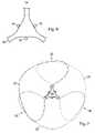
- FIG. 8is a diagram of a top view of a parabolic antenna module with antenna spacers in accordance with one embodiment of the present invention.
- FIG. 9is a diagram of a perspective view of a parabolic antenna module with antenna spacers in accordance with one embodiment of the present invention.
- FIG. 10is a diagram of a top view of coverage areas of a parabolic antenna module with antenna spacers in accordance with one embodiment of the present invention.
- FIG. 11is a diagram of a top view of a hexagonal antenna module in accordance with one embodiment of the present invention.
- FIG. 12is a diagram of a perspective view of a hexagonal antenna module in accordance with one embodiment of the present invention.
- FIG. 13is a diagram of a top view of coverage areas of a hexagonal antenna module in accordance with one embodiment of the present invention.
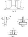
- FIG. 14is a diagram of a side view of a rectangular antenna module with bottom angled shield in accordance with one embodiment of the present invention.
- FIG. 15is a diagram of a perspective view of a rectangular antenna module with bottom angled shield in accordance with one embodiment of the present invention.
- FIG. 16is a diagram of a side view of a rectangular antenna module with top and bottom angled shield in accordance with one embodiment of the present invention.
- FIG. 17is a diagram of a perspective view of a rectangular antenna module with top and bottom angled shield in accordance with one embodiment of the present invention.
- FIG. 18is a diagram of a perspective view of antenna covers with mounting base in accordance with one embodiment of the present invention.
- FIG. 19is a diagram of a side view of antenna covers with mounting base in accordance with one embodiment of the present invention.
- FIG. 20is a diagram of a side view of an antenna covers with mounting base in an upright placement with shields in accordance with one embodiment of the present invention.
- FIG. 21is a diagram of a side view of an antenna covers with mounting base in an upright placement with a radio placed between with shields in accordance with one embodiment of the present invention.
- FIG. 22is a diagram of a top view of a triangular antenna module with antenna spacers in accordance with one embodiment of the present invention.
- FIG. 23is a diagram of a top view of coverage areas of a triangular antenna module with antenna spacers in accordance with one embodiment of the present invention.
- FIG. 24is a diagram of a perspective view of a cubical antenna module with six antenna elements configured to operate as MIMO (Multiple-Input-Multiple-Output) antennas in accordance with one embodiment of the present invention.
- MIMOMultiple-Input-Multiple-Output
- FIG. 25is a diagram of a perspective view of a cubical antenna module with three antenna elements configured to operate as a MIMO antenna in accordance with one embodiment of the present invention.
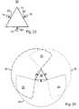
- FIG. 26is a diagram of a top view of a hexagonal antenna module with six antenna elements configured to operate as MIMO antennas in accordance with one embodiment of the present invention.
- FIG. 27is a diagram of a top view of a parabolic antenna module with six antenna elements configured to operate as MIMO antennas in accordance with one embodiment of the present invention.
- FIG. 28is a diagram of a top view of an extended triangular antenna module with antenna spacers and top mounted omni-directional antenna in accordance with one embodiment of the present invention.
- FIG. 29is a diagram of a perspective view of an extended triangular antenna module with antenna spacers and top mounted omni-directional antenna in accordance with one embodiment of the present invention.
- FIG. 30is a diagram of a top view of coverage areas of an extended triangular antenna module with antenna spacers and top mounted omni-directional antenna in accordance with one embodiment of the present invention.
- FIG. 31is a flow diagram of a method for adjusting antenna coverage area shape in accordance with one embodiment of the present invention.
- the present inventionis described partly in terms of functional components and various methods. Such functional components may be realized by any number of components configured to perform the specified functions and achieve the various results.
- the present inventionmay employ various types of antennas, such as, directional, omni-directional, high Q, low Q, patch, quadrifilar helix, adaptive array, MIMO (Multiple-Input-Multiple-Output), beam-forming, and any other type of antenna suitable for the environment or application.
- Shieldsmay be made of any material suitable for the environment, the antenna type, and the application.
- a shieldmay be made of aluminum, steel, copper, plastic, plastic coated with a metallic layer, foam, metal mesh, and any other suitable material and/or combination of materials.
- Shieldsmay substantially and/or partially absorb and/or reflect radio waves. Shields may have any shape suitable to reduce interference and/or to produce a desired coverage area pattern. For example, shields may be triangular, triangular with concave cavities, triangular with extended vertices, parabolic, hexagonal, substantially similar to an I-beam, and any other shape suitable for the environment or application.
- Antennasmay be placed anywhere on the shield and may be attached to the shield in any suitable manner.
- Antenna spacersmay be used to connect the antennas to the shield. Antenna spacers may be of any material, size, and shape. Antennas may interface with the device using the antenna in any suitable manner.
- the present inventionmay be practiced in conjunction with any number of applications and environments, and the systems described are merely exemplary applications of the invention. Further, the present invention may employ any number of conventional or custom techniques for manufacture, testing, connecting, mounting, and communicating with wireless devices.
- Methods and apparatuscomprise at least two antennas and a shield.
- the shieldmay reduce the near-field interference between antennas in substantial close proximity; reduce coupling between antennas in substantial close proximity; shield the antennas from noise generated by system electronics, interference from other system, radios, and/or external noise sources; and shape the coverage area of each of the antennas.
- the effects of near-field interference and detuningmay be reduced by antenna position on the shield, the type of antenna, antenna orientation, the quality of antenna, the types of materials selected for the shield, and antenna spacers.
- Sources of near-field interferencemay include, for example, the near field generated by other antennas in substantial close proximity.
- the shape of the shield and antenna spacersmay affect the shape of each antenna's coverage area and how the individual antenna coverage areas overlap. Overlapping coverage areas from different antennas form virtual sectors. Limiting the overlap of one antenna's coverage area over another antenna's coverage area may reduce interference.
- an antenna module 10in accordance with one embodiment of the invention, comprises three omni-directional antennas 14 , 16 , and 18 and a shield 12 .
- the shield 12from the top view referring to FIG. 1 , is substantially triangular in shape.
- Each antenna 14 , 16 , and 18is placed substantially at one of the triangle vertices.
- the size of the shield 12and therefore the distance between antennas, may be such that the near-field interference between the antennas 14 , 16 , 18 is reduced.
- the shape of the shield and the offset of each antenna relative to the shieldmay form coverage areas 20 , 22 , and 24 for antennas 14 , 16 , and 18 , respectively, such that the coverage area from any antenna does not substantially interfere with any other antenna.
- the antennasmay be of any type and/or configuration.
- the term antennais not limited to a single antenna element, but may be a collection and/or array of antennas elements designed to operate in a coordinate manner.
- Arrays of antennasmay use electronic circuits that may process the signals coming from each antenna element to form a signal that may be similar to the signal from an antenna that has a single antenna element.
- the present inventionmay employ various types of array antennas, for example, adaptive array, MIMO, and other antennas having multiple antenna elements.
- antenna 16may be an antenna with at least two antenna elements such as an array antenna.
- the antenna elements of antenna 16may interface with a single radio.
- FIG. 4antenna 16 may be an antenna with at least two antenna elements such as an array antenna.
- the antenna elements of antenna 16may interface with a single radio.
- FIG. 4referring to FIG.
- antennas 14 , 16 , and 18may each have a single antenna element, but they may each interface to a single radio and may collectively operate as a MIMO antenna.
- antenna 16is a MIMO antenna comprising three separate antenna elements. Each antenna element of the MIMO antenna 16 may be placed on the forward edge of the same triangle vertex. Each antenna element may be spaced along the vertex edge at an appropriate distance for each antenna element to operate in a suitable manner. In another embodiment, referring to FIG. 4 , the antenna elements of MIMO antenna 16 may be spaced along the edge of the triangular shield 12 .
- a shieldas discussed below, may be used to shape the coverage area of an antenna, whether the antenna has a single antenna element or multiple antenna elements.
- Antennas with multiple antenna elementsmay provide additional control over the antenna coverage area in addition to the shield.
- a beam forming antenna arraymay be used in conjunction with a shield.
- antenna 14is an omni-directional antenna that has a single antenna element
- antenna 16is an adaptive array composed of multiple antenna elements
- antenna 18is a directional antenna that has a single antenna element. Any combination of antenna types may be used in conjunction with a shield.
- each antennamay operate at a frequency that may be different from the frequency used by the other antennas.
- the communication protocol and/or channel used by each antennamay be different. In one embodiment, referring to FIG. 6 , antennas 14 , 16 , and 18 each use the same communication protocol, but use the different channels provided by the protocol.
- each antennaAssociated with each antenna is a coverage area.
- the coverage areais the area in which the antenna may receive a transmitted signal or transmit a signal with strength sufficient to be received by another device.
- the shape of the coverage areadepends on the type of antenna.
- the coverage area of an omni-directional antennais substantially spherical.
- the coverage area of a directional antennais substantially a fraction of a sphere.
- the shieldmay alter the shape of the coverage area.
- antenna 14is an omni-directional antenna. In the absence of interference and before antenna 14 is placed proximate to shield 12 , the coverage area of antenna 14 , in two-dimensions, is substantially circular.
- antennas 14 in proximity with shield 12decreases the coverage area of antenna 14 from being substantially circular to covering approximately 270 degrees as shown by coverage area 20 .
- coverage area 20is represented as a sphere with a wedge removed.
- a shieldmay also limit the coverage area of a directional antenna.
- antennas 14 , 16 , and 18are directional antennas with a coverage area of approximately 240 degrees. Placing antennas 14 , 16 , and 18 in parabolic shield 40 limits the antenna coverage areas to approximately 180 degrees with side lobes, as shown in FIG. 10 .
- the overlap of two coverage areas from different antennasforms virtual sectors.
- the overlap of coverage areas 20 and 22form virtual sector 26
- the overlap of coverage areas 22 and 24form virtual sector 28
- the overlap of coverage areas 24 and 20form virtual sector 30 .
- Virtual sectorsare not limited to the overlap of two substantially adjacent coverage areas.
- antenna spacer 82 and antenna 80are placed on top of shield 40 in addition to antennas 14 , 16 and 18 .
- antenna 80is an omni-directional antenna whose area of coverage is represented in two-dimensions by circle 84 .
- Virtual sectors 26 , 28 , and 30still exist; however, the overlap of coverage area 84 with coverage areas 20 , 22 , and 24 also form virtual sectors that are substantially the size of areas of coverage 20 , 22 , and 24 .
- Clients in coverage area 20may be serviced by either antenna 14 and/or antenna 80
- clients in coverage area 22may be serviced by antenna 16 and/or antenna 80 , and so forth.
- clients in virtual sector 26may be serviced by antennas 14 , 16 , and/or 80 .
- Antenna 80serves any desired purpose or performs any type of communication task.
- antenna 80services clients.
- antenna 80communicates with, for example, other antenna modules, substantially adjacent wireless cells, and wireless cells that form a wireless mesh network.
- antenna 80does not transmit signals, but is used solely to detect possible noise sources or other sources of interference.
- Virtual sectorsmay represent areas of high interference or where wireless devices may be serviced by more than one antenna.
- antenna module 10supports the I.E.E.E. 802.11a/b/g wireless communication protocols.
- setting the radios attached to antennas 14 and 16 to operate on the same channelmay result in high levels of interference in virtual sector 26 . Transmissions from antenna 14 may interfere in the operation of antenna 16 and visa versa.
- setting the radios attached to antennas 14 and 16 to different, minimally interfering channelsmay allow a wireless client located in virtual sector 26 to communicate with either antenna 14 on one channel and/or antenna 16 on a different channel.
- antennas 14 , 16 , and 18each operate on a different, minimally interfering channel.
- shields 12 , 36 , 40 , and 44 of FIGS. 4 , 6 , 8 , and 11reduce antenna coupling and/or near-field interference between antennas, thereby permitting the antennas to be placed in closer proximity to each other than if a shield were not used.
- Shield 12 with antenna placement as shown in FIG. 1may be less effective at reducing antenna coupling and/or near-field interference between antennas 14 , 16 , and 18 because the shield provides less isolation between the antennas.
- antenna cover 54may be formed of any material that does not substantially interfere with antenna operation, for example, foam, plastic, cloth, glass, and any other suitable material.
- the antenna cover 54may be used with any antenna type and/or antenna module.
- the antenna cover 54may serve secondary functions such as, for example, facilitating mounting of the antenna and/or antenna module.
- the antenna covers 54may be fastened to a mounting base 56 to form an antenna module that may be use in a variety of circumstances.
- the mounting base 56may be used to mount the antennas and/or antenna modules in addition to the antenna covers 54 .
- a MIMO antennais comprised of at least two antenna elements that interface with the same radio and function in a coordinated manner.
- antennas 14 , 16 , and 18may each have a single antenna element, but they may interface together and function in a coordinated manner to form a MIMO antenna.
- the individual antennas that comprise a MIMO antennamay be of any type, for example, omni-directional, directional, patch, whip, helical, and yagi.
- the antennas that comprise the MIMO antennamay operate as transmit only, receive only, or transmit/receive antennas.
- antennas 14 and 18transmit and receive, while antenna 16 receives only.
- antennas 70 and 76transmit and receive while antenna 72 receives only.
- the signals received through and transmitted from antennas 14 , 16 , and 18may be used in any manner, singly or in combination, to improve reception and/or transmission in a coverage area.
- a shieldmay support any number of MIMO antennas.
- any two antennasmay form a MIMO antenna.
- antennas 70 and 72form a MIMO antenna that interfaces to a first radio while antenna 76 interfaces to a second radio.
- antennas 72 and 76form a MIMO antenna that interfaces to a first radio while antenna 70 interfaces to a second radio.
- antennas 70 , 72 , and 76form a MIMO antenna and interface with the same radio. Increasing the number of single element antennas associated with a shield increases the number of possible combinations for forming MIMO antennas.
- any two antennas selected from the group of antennas 68 , 70 , 72 , 74 , 76 , and 78may operate as a MIMO antenna and interface to a radio.
- antennas 68 and 76operate as a MIMO antenna and interface to a first radio.
- Antenna pairs 70 , 78 and 72 , 74also operate as MIMO antennas and each pair interface with a second and third radio, respectively. This embodiment pairs antennas that are positioned orthogonally to each other.
- any two antennasmay be used to form a MIMO antenna.
- antenna pairs 68 and 70 , 72 and 74 , 76 and 78each form MIMO antennas and interface to a first, second and third radio respectively.
- the antenna pairs 68 and 74 , 70 and 76 , 72 and 78form MIMO antennas. More than two antennas may operate together to form a MIMO antennas.
- antennas 68 , 72 , and 76operate as one MIMO antenna while antennas 70 , 72 and 74 operate as another MIMO antenna.
- each antenna of each MIMO combinationis orthogonal to each other.
- the antennas shown in FIGS. 26-27may also be divided into groups of three to form separate MIMO antennas.
- antennas 68 , 72 , and 76form one MIMO antenna and antennas 70 , 74 , and 78 form another MIMO antenna. More than three antennas may form a MIMO antenna.
- Each antenna used to form a MIMO antennamay have at least one of transmit and receive, transmit only, and receive only mode of operation.
- each antenna 70 , 72 , and 76may separately operate as a MIMO antenna and interface with separate radios.
- a shieldmay reduce coupling and/or near-field interference between antennas in substantial close proximity, shield the antennas from noise generated by system electronics, and shape the coverage area of each of the antennas.
- Antennasmay be considered to be in substantial close proximity to each other when, referring to FIG. 4 , distance 64 between the antennas is less than about two times the length of the frequency used by the antennas.
- Use of a shield to reduce interference between antennasimproves antenna performance and may reduce the distance required between antennas for a desired level of performance.
- the shape of some shieldsmay be better adapted to reduce near-field interference and/or coupling between antennas in substantial close proximity. For example, referring to FIG.
- antennas 14 , 16 , and 18are positioned linearly with little shield isolation between the antennas.
- the shield shape when combined with the antenna placementmay be less able to block near-field interference between antennas.
- the shape of shield 12 with antennas positioned at the verticesmay be best adapted to shape the coverage areas, but be less effective at reducing near-field interference and/or coupling between antennas.
- near-field interference and/or coupling between the antennas of antenna module 10may be reduced by spacing the antennas farther from each other; however, the distance required between the antennas to provide a substantial reduction in near-field interference and/or coupling may result in an antenna module, wherein the antennas are not in substantial close proximity to each other.
- Shield 12is used to reduce near-field interference and/or coupling between antennas by modifying the antenna positions relative to the antenna. Referring to FIG. 4 , positioning antennas 12 , 14 , and 16 on the sides of shield 12 places a substantial portion of the shield between the antennas. The shield between the antennas may block and/or reduce near-field interference and/or coupling between antennas, thereby reducing interference between antennas in substantial close proximity.
- Shields 36 , 40 , 44 , 48 , and 52 of FIGS. 6 , 8 , 11 , 14 , and 16respectively reduce near-field interference and/or coupling between antennas in substantial close proximity because the shield provides a measure of isolation between the antennas.
- the shape of the shieldmay modify the shape of the antenna coverage areas, as described above.
- a shieldmay be constructed of any material that attenuates near-field interference and/or coupling between antennas. Additionally, the thickness, height, and shape of the shield may be modified to further reduce near-field interference and/or coupling between antennas.
- a shieldmay have any material composition, for example, a shield may be solid, hollow, or substantially solid with cavities. Radios and/or system electronics may be placed and/or anchored in a shield hollow and/or cavity. Shields may be formed of any material or combination of materials suitable for the application.
- Antenna performancemay also be negatively impacted by detuning an antenna.
- antennashave a center frequency and a range around the center frequency at which they function efficiently.
- An antennabecomes detuned when its center frequency and the range around the center frequency shift to a higher or a lower frequency and/or when the center frequency remains unaffected, but the bandwidth around the center frequency decreases.
- Antennasmay become detuned when placed in close proximity with materials that detune that type of antenna. For example, placing an omni-directional antenna close to metal may detune the antenna. Placing a mobile phone antenna close to the human body may detune the antenna.
- the detuning effect of a shield on an antennamay be reduced by, for example, designing an antenna that requires proximity to the shield to become tuned, forming the shield from a material that does not detune the antenna, and/or offsetting the antenna from the shield with an antenna spacer.
- the antenna performance characteristicsare selected such that when the antenna is used in close proximity to the shield, the antenna operates at the desired center frequency with the desired bandwidth, but when the antenna is used apart from the shield, it becomes detuned.
- antennas 14 , 16 and 18are offset from the shield using antennas spacers 62 .
- the size of the antenna spacer 62 and the amount of the offsetmay be selected to reduce the amount of detuning to a desire level.
- a shieldmay also alter the shape of an antenna's coverage area.
- the shieldmay alter the shape of an antenna's area of coverage in any manner suitable for the environment or application.
- antenna module 10comprises three antennas 14 , 16 , and 18 , and a substantially triangular shaped shield 12 . Each antenna is positioned at a vertex of the shield 12 .
- Antennas 14 , 16 , and 18may connect directly to shield 12 and/or to antenna spacers.
- shield 12reduces each coverage area 20 , 22 , and 24 of antennas 14 , 16 , and 18 respectively to an area less than substantially spherical.
- the coverage areas 20 , 22 , and 24may be representative of the shape of the resulting coverage areas in two dimensions.
- the coverage areasmay overlap to form virtual sectors 26 , 28 , and 30 .
- antenna module 32comprises antennas 14 , 16 , and 18 , and substantially triangular shaped shield 12 .
- each antennais positioned along an edge of the shield 12 .
- Antennas 14 , 16 , and 18may be mounted directly to shield 12 and/or to antenna spacers.
- shield 12reduces each coverage area 20 , 22 , and 24 of antennas 14 , 16 , and 18 respectively to an area less than substantially spherical.
- the coverage areas 20 , 22 , and 24may be representative of the shape of the resulting coverage areas in two dimensions. The coverage areas may overlap to form virtual sectors 26 , 28 , and 30 .
- antenna module 34comprises antennas 14 , 16 , and 18 , and shield 36 .
- the shape of shield 36is substantially triangular with the vertices extended and enlarged.
- Each antenna 14 , 16 , and 18is positioned along an edge of the shield 36 .
- Antennas 14 , 16 , and 18may be mounted directly to shield 36 and/or to antenna spacers.
- shield 36reduces each coverage area 20 , 22 , and 24 of antennas 14 , 16 , and 18 , respectively, to an area less than substantially spherical.
- the coverage areas 20 , 22 , and 24referring to FIG. 7 , may be representative of the shape of the resulting coverage areas in two dimensions.
- the coverage areasmay overlap to form virtual sectors 26 , 28 , and 30 .
- antenna module 38comprises antennas 14 , 16 , and 18 , and shield 40 .
- the shape of shield 40is substantially parabolic on the inner curves.
- the antennas 14 , 16 , and 18are positioned in the parabolic curves of the shield 40 .
- Antennas 14 , 16 , and 18may be mounted to shield 40 using antenna spacer 62 and/or directly to shield 40 .
- shield 40reduces each coverage area 20 , 22 , and 24 of antennas 14 , 16 , and 18 , respectively, to an area less than substantially spherical. Referring to FIG.
- the coverage areas 20 , 22 , and 24may be representative of the shape of the resulting coverage areas in two dimensions.
- the shape of the parabolic inner curve of shield 40 and offset of the antenna spacermay determine whether coverage areas 20 , 22 , and 24 overlap to form virtual sectors.
- the parabolic curves of shield 40are sufficiently steep to substantially reduce overlap between the coverage areas.
- the parabolic curves of shield 40are sufficiently shallow that coverage areas 20 , 22 , and 24 overlap and form virtual sectors.
- the shape of the coverage areasmay also be modified by adjusting the size of the antenna spacer.
- antenna module 42comprises antennas 14 , 16 , and 18 , and shield 44 .
- the shape of shield 44is substantially hexagonal.
- Each antenna 14 , 16 , and 18is positioned substantially in the center of a non-adjacent face of the shield 44 .
- Antennas 14 , 16 , and 18may be mounted directly to shield 44 and/or to antenna spacers.
- shield 44reduces each coverage area 20 , 22 , and 24 of antennas 14 , 16 , and 18 respectively to an area less than substantially spherical.
- the coverage areas 20 , 22 , and 24referring to FIG. 13 , may be representative of the shape of the resulting coverage areas in two dimensions.
- the coverage areasmay overlap to form virtual sectors 26 , 28 , and 30 .
- antenna module 46comprises antennas 14 , and 16 , and shield 48 .
- the shape of shield 48is substantially rectangular with an angled shield along the bottom.
- Each antenna 14 , and 16is positioned on a face of the shield 48 .
- Antennas 14 and 16may be mounted directly to shield 48 and/or to antenna spacers.
- shield 48reduces the coverage area of each antenna 14 and 16 to an area less than substantially spherical.
- the angled shield along the bottomadditionally reduces the lower part of the coverage area and may reduce interference from system electronics and/or radios mounted below the antenna assembly.
- the inventioncontemplates any number of antennas that may be mounted to shield 48 . In one embodiment, four antennas, two on each side, are mounted to shield 48 .
- the angled shield along the bottommay also improve mechanical system stability.
- antenna module 50comprises antennas 14 , and 16 , and shield 52 .
- the shape of shield 52is substantially rectangular with an angled shield along the top and bottom.
- Each antenna 14 , and 16is positioned on a face of the shield 52 .
- Antennas 14 and 16may be mounted directly to shield 52 and/or to antennas spacers.
- shield 52reduces the coverage area of each antenna 14 and 16 to an area less than substantially spherical.
- the angled shields along the top and the bottomreduce the top and the bottom part of the coverage area respectively and may reduce interference from system electronics and/or radios positioned above and/or below antenna module 50 .
- the inventioncontemplates any number of antennas that may be mounted to shield 52 .
- four antennas, two on each side,are mounted to shield 52 .
- the angled top and bottom of shield 52may be used in conjunction with shields having other shapes, for example, shields 12 , 36 , 40 , and 44 of FIGS. 4 , 6 , 8 , and 11 respectively.
- the antenna shieldmay be an integral part of the case used to enclose the radio and/or other system electronics.
- an antennamay be mounted directly to a shield or it may be offset from the shield.
- An antenna spacermay be used to offset an antenna and/or the active element of an antenna away from the shield.
- the antennasmay be offset from the shield for any reason and to achieve any result such as, for example, to reduce detuning, to reduce near-field interference between antennas, to reduce coupling between antennas, to achieve a desired distance between antennas, and/or to adjust antenna coverage area.
- antennas 14 , 16 , and 18are mounted directly to the shield 12 .
- antennas 14 , 16 , and 18are mounted to an antenna spacer 62 and the antenna spacer 62 is mounted to the shield.
- the antenna spacer 62may be formed of any material, have any shape, and be of any size. In one embodiment, referring to FIG. 22 , the antenna spacer 62 material is selected to have a minimal detuning effect on antennas 14 , 16 , and 18 . The size of antenna spacer 62 is selected to position antennas 14 , 16 , and 18 at a sufficient distance to decrease the detuning effect the material of shield 40 may have on antennas 14 , 16 , and 18 . Antenna spacer 62 may also be used to increase the distance between antennas 14 , 16 and 18 to reduce the effects of near-field interference and/or coupling between antennas.
- the size of antenna spacer 62is adjusted to position each antenna away from any other antenna a distance of about 1.25 times the wavelength of the frequency used by the antennas.
- the size of antennas spacer 62may also be adjusted to alter the shape of the antenna coverage area and/or virtual sector size.
- the shape of coverage areas 20 , 22 , 24 and virtual sectors 26 , 28 , 30may be represented by FIG. 5 when antennas 14 , 16 , 18 are mounted directly to shield 12 .
- FIGS. 4-5the shape of coverage areas 20 , 22 , 24 and virtual sectors 26 , 28 , 30 may be represented by FIG. 5 when antennas 14 , 16 , 18 are mounted directly to shield 12 .
- FIGS. 4-5the shape of coverage areas 20 , 22 , 24 and virtual sectors 26 , 28 , 30 may be represented by FIG. 5 when antennas 14 , 16 , 18 are mounted directly to shield 12 .
- antenna spacers 62may be formed of any material, for example, metal, plastic, resin, wood, paper, foam, and any other suitable material. Referring to FIG. 22 , antenna spacer 62 may connect to shield 40 in any suitable manner. Antennas 14 , 16 , and 18 , may connect to antenna spacer 62 in any suitable manner. Antenna spacers 62 may have any material structure, for example, hollow, solid, a honeycomb structure, and any other material structure suitable for the application and environment. Antennas having multiple antenna elements may use a separate antenna spacer 62 for each antenna element. Antenna spacer 62 may be used with any antenna type or shield shape.
- a mounting base 56may be used to mount and retain antenna cover 54 in position.
- Mounting base 56may be of any material suitable for the application or environment.
- mounting base 56may be formed of metal, wood, plastic, foam, and any other suitable material.
- the mounting baseis made of plastic.
- the antenna cover 54may be of any size or shape suitable for the application or environment.
- the antenna cover 54is substantially rectangular and made of plastic.
- the antenna covermay be approximately a quarter of a sphere in shape.
- the antenna covermay be made of any material and/or be open at any part of the antenna cover 54 .
- antenna cover 54is enclosed on all sides but one and is made of a plastic that does not interfere with antenna transmission and reception. Antennas inside the antenna cover 54 may be mounted to the antenna cover 54 and/or the mounting base 56 .
- the antenna cover 54 and the mounting basemay form an antenna module suitable for use in a variety of situations.
- antennasare mounted to mounting base 56 and covered by antenna covers 54 .
- the resulting moduleis placed on top of a radio 58 .
- the antennas inside the antenna covers 54are omni-directional and the radio 58 may be encased in metal and act as a shield between the antennas that shapes their coverage areas.
- the antennas inside the antenna covers 54are omni-directional and at least one shield 60 is mounted to the mounting base 56 between the antenna covers 54 . Shield 60 shapes the coverage areas of the antennas inside antenna covers 54 .
- the resulting moduleis placed on top of radio 58 .
- the mounting base 56may be made of material that reflects radio signals if shielding between the antennas and the radio is desirable.
- the radiois placed in between two shields 60 positioned between antennas covers 54 .
- any of the above componentsmay be used to implement any of the methods discussed herein. Alteration of an antenna's coverage area may be accomplished in any manner; for example, the shape, size, and overlap of coverage areas may be modified by adjusting shield shape, shield size, antenna position, and antenna spacer size.
- a shieldmay have any shape to produce a desired coverage area pattern. Exemplary shield shapes are shown in FIGS. 1 , 6 , 8 , 11 , 15 , 17 , and 21 . The coverage areas that may result are shown in FIGS. 3 , 5 , 7 , 10 , 13 , and 23 .
- the exemplary embodimentsdemonstrate that shield shape may modify antenna coverage areas and form virtual sectors. Shield shape is not limited to being symmetrical.
- one side of a three sided shieldmay have a parabolic indentation, another side may be flat and a third side may be flat with top and bottom angled shields.
- Shield sizemay be consider an aspect if its shape. Just as the invention contemplates any shape of a shield, the size of a shield may be adjusted to achieve the desired shape of antenna coverage areas.
- Antennasmay be position at any location on a shield and at any location relative to another antenna to attain the desired coverage pattern.
- the effects of different antenna positions relative to a shield of substantially similar shapeare illustrated by exemplary embodiments in FIGS. 1-3 and FIGS. 4-5 .
- Moving antennas 14 , 16 , and 18 from the vertices of shield 12 , as shown in FIG. 1 , to the sides of shield 12 , as shown in FIG. 4results in reduced coverage areas.
- Coverage areas 20 , 22 , and 24 as shown in FIG. 3are reduced in area to the coverage areas 20 , 22 , and 24 shown in FIG. 5 when antennas 14 , 16 , and 18 are moved from the vertices of shield 12 to the sides of shield 12 .
- FIGS. 1Moving antennas 14 , 16 , and 18 from the vertices of shield 12 , as shown in FIG. 1 , to the sides of shield 12 , as shown in FIG. 4 , results in reduced coverage areas.
- an antennais mounted away from a shield using an antenna spacer 62 of any size.
- An antenna spacer 62may connect to the shield at any angle and may be of any length, size, and shape. Modifying the size of the antenna spacer 62 and/or the resulting offset of the antennas from the shield may alter the area of coverage of the antenna which is connected to the antenna spacer.
- mounting antennas 14 , 16 , and 18 to shield 12 with no or very short antenna spacers 62may result in the coverage areas 20 , 22 , and 24 shown in FIG. 5 .
- Adding antenna spacers 62 or increasing the length of the antenna spacers 62increases coverage areas 20 , 22 , and 24 and the size of virtual sectors 26 , 28 and 30 .
- an exemplary embodiment of a method for altering the shape of an antenna's coverage areaincludes selecting the desired coverage area shape, an antenna and a shield (step 86 ).
- An antenna spacer having a length, a size, and a shapeis selected (steps 88 - 92 ). All possible mounting positions on the shield are marked as being untested (step 94 ).
- the antennais connected to the antenna spacer and the antenna spacer is mounted to the shield at a position not previously tested (step 96 ). Once the antenna spacer is mounted, the shape of the antenna coverage area is compared to the desired coverage area shape (step 100 ).
- the methodcycles through changing mounting positions (step 102 ), selecting antenna spacers of different shapes (step 104 ), selecting antenna spacers of different sizes (step 106 ), and selecting antenna spacers of different lengths (step 110 ). Once all available mounting positions, antenna spacer shapes, sizes, and lengths have been tried without achieving a substantial match between the antenna coverage area shape and the desired coverage area shape, the algorithm signals that the shape has not been achieved (step 108 ), and terminates.
Landscapes
- Engineering & Computer Science (AREA)
- Computer Networks & Wireless Communication (AREA)
- Physics & Mathematics (AREA)
- Electromagnetism (AREA)
- Signal Processing (AREA)
- Details Of Aerials (AREA)
- Aerials With Secondary Devices (AREA)
- Variable-Direction Aerials And Aerial Arrays (AREA)
Abstract
Description
Claims (28)
Priority Applications (5)
| Application Number | Priority Date | Filing Date | Title |
|---|---|---|---|
| US11/275,619US7489282B2 (en) | 2005-01-21 | 2006-01-19 | Method and apparatus for an antenna module |
| EP06719120AEP1856765A2 (en) | 2005-01-21 | 2006-01-20 | Method and apparatus for an antenna module having a shield |
| CA002595179ACA2595179A1 (en) | 2005-01-21 | 2006-01-20 | Method and apparatus for an antenna module having a shield |
| KR1020077016820AKR20070095354A (en) | 2005-01-21 | 2006-01-20 | Method and apparatus for antenna module |
| PCT/US2006/002156WO2006078967A2 (en) | 2005-01-21 | 2006-01-20 | Method and apparatus for an antenna module having a shield |
Applications Claiming Priority (3)
| Application Number | Priority Date | Filing Date | Title |
|---|---|---|---|
| US64602405P | 2005-01-21 | 2005-01-21 | |
| US67456805P | 2005-04-25 | 2005-04-25 | |
| US11/275,619US7489282B2 (en) | 2005-01-21 | 2006-01-19 | Method and apparatus for an antenna module |
Publications (2)
| Publication Number | Publication Date |
|---|---|
| US20060164320A1 US20060164320A1 (en) | 2006-07-27 |
| US7489282B2true US7489282B2 (en) | 2009-02-10 |
Family
ID=36215562
Family Applications (1)
| Application Number | Title | Priority Date | Filing Date |
|---|---|---|---|
| US11/275,619Expired - Fee RelatedUS7489282B2 (en) | 2005-01-21 | 2006-01-19 | Method and apparatus for an antenna module |
Country Status (5)
| Country | Link |
|---|---|
| US (1) | US7489282B2 (en) |
| EP (1) | EP1856765A2 (en) |
| KR (1) | KR20070095354A (en) |
| CA (1) | CA2595179A1 (en) |
| WO (1) | WO2006078967A2 (en) |
Cited By (43)
| Publication number | Priority date | Publication date | Assignee | Title |
|---|---|---|---|---|
| US20090109103A1 (en)* | 2007-10-31 | 2009-04-30 | Searete Llc, A Limited Liability Corporation | Electromagnetic compression apparatus, methods, and systems |
| US20090109112A1 (en)* | 2007-10-31 | 2009-04-30 | Searete Llc, A Limited Liability Corporation Of The State Of Delaware | Electromagnetic compression apparatus, methods, and systems |
| US20090167138A1 (en)* | 2007-12-29 | 2009-07-02 | Tsinghua University | Thermionic electron source |
| US20090218523A1 (en)* | 2008-02-29 | 2009-09-03 | Searete Llc, A Limited Liability Corporation Of The State Of Delaware | Electromagnetic cloaking and translation apparatus, methods, and systems |
| US20090218524A1 (en)* | 2008-02-29 | 2009-09-03 | Searete Llc, A Limited Liability Corporation Of The State Of Delaware | Electromagnetic cloaking and translation apparatus, methods, and systems |
| US20090296225A1 (en)* | 2008-05-30 | 2009-12-03 | Searete Llc, A Limited Liability Corporation Of The State Of Delaware | Negatively-refractive focusing and sensing apparatus, methods, and systems |
| US20090294668A1 (en)* | 2008-05-30 | 2009-12-03 | Searete Llc, A Limited Liability Corporation Of The State Of Delaware | Focusing and sensing apparatus, methods, and systems |
| US20090296076A1 (en)* | 2008-05-30 | 2009-12-03 | Searete Llc, A Limited Liability Corporation Of The State Of Delaware | Negatively-refractive focusing and sensing apparatus, methods, and systems |
| US20090296236A1 (en)* | 2008-05-30 | 2009-12-03 | Searete Llc, A Limited Liability Corporation Of The State Of Delaware | Emitting and focusing apparatus, methods, and systems |
| US20090296077A1 (en)* | 2008-05-30 | 2009-12-03 | Searete Llc. | Negatively-refractive focusing and sensing apparatus, methods, and systems |
| US20090296224A1 (en)* | 2008-05-30 | 2009-12-03 | Searete Llc, A Limited Liability Corporation Of The State Of Delaware | Emitting and negatively-refractive focusing apparatus, methods, and systems |
| US20090316279A1 (en)* | 2008-05-30 | 2009-12-24 | Searete Llc, A Limited Liability Corporation Of The State Of Delaware. | Emitting and focusing apparatus, methods, and systems |
| US20100027130A1 (en)* | 2008-07-25 | 2010-02-04 | Searete Llc, A Limited Liability Corporation Of The State Of Delaware | Emitting and negatively-refractive focusing apparatus, methods, and systems |
| US20100033833A1 (en)* | 2008-05-30 | 2010-02-11 | Searete Llc, A Limited Liability Corporation Of The State Of Delaware | Emitting and negatively-refractive focusing apparatus, methods, and systems |
| US20100033832A1 (en)* | 2008-08-07 | 2010-02-11 | Searete Llc, A Limited Liability Corporation Of The State Of Delaware | Negatively-refractive focusing and sensing apparatus, methods, and systems |
| US7777962B2 (en) | 2008-05-30 | 2010-08-17 | The Invention Science Fund I, Llc | Negatively-refractive focusing and sensing apparatus, methods, and systems |
| US20100277808A1 (en)* | 2008-05-30 | 2010-11-04 | Searete Llc, A Limited Liability Corporation Of The State Of Delaware | Emitting and negatively-refractive focusing apparatus, methods, and systems |
| US20100277807A1 (en)* | 2008-05-30 | 2010-11-04 | Searete Llc | Negatively-refractive focusing and sensing apparatus, methods, and systems |
| US20130162499A1 (en)* | 2011-11-15 | 2013-06-27 | Juniper Networks, Inc. | Apparatus for implementing cross polarized integrated antennas for mimo access points |
| US8737244B2 (en) | 2010-11-29 | 2014-05-27 | Rosemount Inc. | Wireless sensor network access point and device RF spectrum analysis system and method |
| US8736982B2 (en) | 2008-05-30 | 2014-05-27 | The Invention Science Fund I Llc | Emitting and focusing apparatus, methods, and systems |
| US8773775B2 (en) | 2008-05-30 | 2014-07-08 | The Invention Science Fund I Llc | Emitting and negatively-refractive focusing apparatus, methods, and systems |
| US8773776B2 (en) | 2008-05-30 | 2014-07-08 | The Invention Science Fund I Llc | Emitting and negatively-refractive focusing apparatus, methods, and systems |
| US9191086B2 (en) | 2011-11-15 | 2015-11-17 | Juniper Networks, Inc. | Methods and apparatus for balancing band performance |
| US9485649B2 (en) | 2008-09-25 | 2016-11-01 | Fisher-Rosemount Systems, Inc. | Wireless mesh network with pinch point and low battery alerts |
| US9496931B2 (en) | 2006-02-28 | 2016-11-15 | Woodbury Wireless, LLC | Methods and apparatus for overlapping MIMO physical sectors |
| US9755129B2 (en) | 2011-06-29 | 2017-09-05 | Rosemount Inc. | Integral thermoelectric generator for wireless devices |
| US20170331194A1 (en)* | 2016-05-10 | 2017-11-16 | Wistron Neweb Corp. | Communication device |
| EP3319241A1 (en)* | 2016-11-08 | 2018-05-09 | V-Count Teknoloji A.S. | Device for locating mobile devices |
| US10022277B2 (en) | 2013-03-13 | 2018-07-17 | Hill-Rom Services, Inc. | Methods and apparatus for the detection of moisture and multifunctional sensor systems |
| US20180277928A1 (en)* | 2017-03-27 | 2018-09-27 | Xirrus, Inc. | Triple mimo antenna array and wireless network access device |
| US10115291B2 (en) | 2016-04-26 | 2018-10-30 | Hill-Rom Services, Inc. | Location-based incontinence detection |
| US10159607B2 (en) | 2015-11-16 | 2018-12-25 | Hill-Rom Services, Inc. | Incontinence detection apparatus |
| USD863268S1 (en) | 2018-05-04 | 2019-10-15 | Scott R. Archer | Yagi-uda antenna with triangle loop |
| US10559187B2 (en) | 2011-07-19 | 2020-02-11 | Hill-Rom Services, Inc. | Moisture detection system |
| US10645628B2 (en) | 2010-03-04 | 2020-05-05 | Rosemount Inc. | Apparatus for interconnecting wireless networks separated by a barrier |
| US10653567B2 (en) | 2015-11-16 | 2020-05-19 | Hill-Rom Services, Inc. | Incontinence detection pad validation apparatus and method |
| US10716715B2 (en) | 2017-08-29 | 2020-07-21 | Hill-Rom Services, Inc. | RFID tag inlay for incontinence detection pad |
| US10945892B2 (en) | 2018-05-31 | 2021-03-16 | Hill-Rom Services, Inc. | Incontinence detection system and detectors |
| US11707387B2 (en) | 2015-11-16 | 2023-07-25 | Hill-Rom Services, Inc. | Incontinence detection method |
| US11712186B2 (en) | 2019-09-30 | 2023-08-01 | Hill-Rom Services, Inc. | Incontinence detection with real time location information |
| US11950987B2 (en) | 2019-05-21 | 2024-04-09 | Hill-Rom Services, Inc. | Manufacturing method for incontinence detection pads having wireless communication capability |
| US12048613B2 (en) | 2019-09-30 | 2024-07-30 | Hill-Rom Services, Inc. | Incontinence detection system |
Families Citing this family (13)
| Publication number | Priority date | Publication date | Assignee | Title |
|---|---|---|---|---|
| CA2715381A1 (en)* | 2008-02-13 | 2009-08-20 | Selex Sistemi Integrati S.P.A. | Radio device for a wireless network |
| TWI351134B (en)* | 2008-03-24 | 2011-10-21 | First Int Computer Inc | Multi-antenna module having specific disposal |
| CN101582538B (en)* | 2008-05-16 | 2013-02-13 | 华硕电脑股份有限公司 | Array antenna |
| US8363580B2 (en)* | 2009-03-31 | 2013-01-29 | Rosemount Inc. | Disparate radios in a wireless mesh network |
| CN201438500U (en)* | 2009-06-05 | 2010-04-14 | 鸿富锦精密工业(深圳)有限公司 | Multiple Input Output Electronics |
| CN104521264A (en)* | 2012-06-06 | 2015-04-15 | 伊甸石通信股份有限公司 | Adjacent network aware self organizing network system |
| TWI502813B (en)* | 2012-07-13 | 2015-10-01 | Wistron Corp | Phased array smart antennas and operating methods thereof |
| US10701515B2 (en)* | 2015-12-10 | 2020-06-30 | Datalogic Ip Tech S.R.L. | Multi-beacon-based location system and method |
| US20180146906A1 (en) | 2016-11-29 | 2018-05-31 | Hill-Rom Services, Inc. | System and method for determining incontinence device replacement interval |
| CN110034400A (en) | 2018-01-05 | 2019-07-19 | 台达电子工业股份有限公司 | Antenna assembly and antenna system |
| CN112544013B (en) | 2018-08-17 | 2022-06-28 | 华为技术有限公司 | Antenna assembly, antenna tuning-free method and device |
| WO2020256760A1 (en)* | 2019-06-19 | 2020-12-24 | John Mezzalingua Associates, LLC | Toroidal gradient index lens for omni and sector antennas |
| US11569892B2 (en)* | 2020-11-19 | 2023-01-31 | Samsung Electronics Co., Ltd. | Method and apparatus for beam management in multi-module devices |
Citations (98)
| Publication number | Priority date | Publication date | Assignee | Title |
|---|---|---|---|---|
| US3803625A (en) | 1972-12-18 | 1974-04-09 | Itt | Network approach for reducing the number of phase shifters in a limited scan phased array |
| US4128740A (en) | 1977-02-14 | 1978-12-05 | Motorola, Inc. | Antenna array for a cellular RF communications system |
| EP0022991A1 (en) | 1979-07-13 | 1981-01-28 | Siemens Aktiengesellschaft | Antenna arrangement for masking the side lobe pattern of a highly directional main antenna and its use with a panoramic search radar antenna |
| JPS5720002A (en) | 1980-07-10 | 1982-02-02 | Anritsu Corp | Short backfire antenna |
| EP0435283A1 (en) | 1989-12-28 | 1991-07-03 | Nec Corporation | Antenna arrangement system capable of reducing co-channel interference |
| US5113525A (en) | 1989-11-06 | 1992-05-12 | Mitsubishi Denki Kabushiki Kaisha | Linear-modulation type radio transmitter |
| US5265263A (en) | 1990-04-06 | 1993-11-23 | Stc Plc | Handover techniques |
| US5276907A (en) | 1991-01-07 | 1994-01-04 | Motorola Inc. | Method and apparatus for dynamic distribution of a communication channel load in a cellular radio communication system |
| EP0622925A1 (en) | 1993-04-30 | 1994-11-02 | International Business Machines Corporation | A multiaccess scheme for mobile integrated local area networks |
| US5365571A (en) | 1993-05-24 | 1994-11-15 | Hughes Aircraft Company | Cellular system having frequency plan and cell layout with reduced co-channel interference |
| EP0660631A2 (en) | 1993-12-27 | 1995-06-28 | Nec Corporation | Channel allocation system for communication systems and an apparatus thereof |
| EP0668627A1 (en) | 1994-02-16 | 1995-08-23 | Northern Telecom Limited | Base station antenna arrangement |
| US5491833A (en) | 1993-12-27 | 1996-02-13 | Nec Corporation | Mobile radio communication system having radio zones of sector configurations and antenna selecting method employed therein |
| EP0715478A2 (en) | 1994-11-28 | 1996-06-05 | Texas Instruments Inc. | Low power, short range point-to-multipoint communications system |
| US5548813A (en) | 1994-03-24 | 1996-08-20 | Ericsson Inc. | Phased array cellular base station and associated methods for enhanced power efficiency |
| US5606727A (en) | 1993-12-22 | 1997-02-25 | Nec Corporation | Method and apparatus for adaptive channel assignment in a mobile communication system |
| US5613200A (en) | 1993-03-17 | 1997-03-18 | Nec Corporation | Method of allocating radio channels for mobile communication system |
| EP0782361A2 (en) | 1995-12-29 | 1997-07-02 | AT&T Corp. | System and method for management of neighbor-channel interference with power control and directed channel assignment |
| US5649292A (en) | 1994-10-31 | 1997-07-15 | Airnet Communications Corporation | Obtaining improved frequency reuse in wireless communication systems |
| EP0785695A2 (en) | 1995-12-29 | 1997-07-23 | AT&T Corp. | System and method for managing neighbor-channel interference in channelized cellular systems |
| US5684491A (en) | 1995-01-27 | 1997-11-04 | Hazeltine Corporation | High gain antenna systems for cellular use |
| US5771449A (en) | 1994-03-17 | 1998-06-23 | Endlink, Inc. | Sectorized multi-function communication system |
| WO1998042150A2 (en) | 1997-03-14 | 1998-09-24 | At & T Corp. | Downlink smart antennas for is-54/is-136 tdma systems |
| US5835859A (en) | 1995-10-13 | 1998-11-10 | Airnet Communications Corporation | Method for frequency allocation and assignment in wireless communication systems |
| EP0895436A2 (en) | 1997-07-31 | 1999-02-03 | Nortel Networks Corporation | Combined multi-beam & sector coverage antenna array |
| US5901356A (en) | 1994-08-04 | 1999-05-04 | Northern Telecom Limited | Channel allocation pattern in a cellular communications system |
| US5960349A (en) | 1997-05-20 | 1999-09-28 | Northern Telecom | Enhanced cellular layout for CDMA networks having six-sectored cells |
| WO1999052311A1 (en) | 1998-04-03 | 1999-10-14 | Telefonaktiebolaget Lm Ericsson (Publ) | Method and system for handling radio signals in a radio base station |
| JP2000031721A (en) | 1998-07-14 | 2000-01-28 | Hideo Suyama | Built-in antenna system |
| EP0980111A1 (en) | 1998-05-20 | 2000-02-16 | Libertel N.V. | Antenna device of a base station of a mobile telecommunication network. |
| US6055230A (en) | 1997-09-05 | 2000-04-25 | Metawave Communications Corporation | Embedded digital beam switching |
| EP1014740A1 (en) | 1998-12-22 | 2000-06-28 | Motorola, Inc. | Reduction of co-channel interference in cellular communications systems |
| US6104935A (en) | 1997-05-05 | 2000-08-15 | Nortel Networks Corporation | Down link beam forming architecture for heavily overlapped beam configuration |
| US6118767A (en) | 1997-11-19 | 2000-09-12 | Metawave Communications Corporation | Interference control for CDMA networks using a plurality of narrow antenna beams and an estimation of the number of users/remote signals present |
| US6128497A (en) | 1997-12-03 | 2000-10-03 | Nortel Networks Limited | High capacity cell planning based on fractional frequency reuse |
| US6154654A (en) | 1998-05-07 | 2000-11-28 | Ericsson Inc. | System and method for frequency reuse in a four cell plan |
| WO2001001582A2 (en) | 1999-04-29 | 2001-01-04 | Telefonaktiebolaget Lm Ericsson (Publ) | Integrated adaptive phased arrays and sector antennas |
| US6178328B1 (en) | 1998-06-11 | 2001-01-23 | Nortel Networks Corporation | Method and system for solving cellular communications frequency planning problem |
| US6229486B1 (en) | 1998-09-10 | 2001-05-08 | David James Krile | Subscriber based smart antenna |
| US6272337B1 (en) | 1999-05-17 | 2001-08-07 | Nortel Networks Limited | Testing a mobile communications system |
| US6278723B1 (en) | 2000-03-08 | 2001-08-21 | Motorola, Inc. | Method and apparatus for minimizing a probability of self-interference among neighboring wireless networks |
| KR200235289Y1 (en) | 2000-10-09 | 2001-10-10 | (주)하이게인안테나 | Directivity antenna for suppressing sideband in side direction |
| US6304762B1 (en) | 1996-12-23 | 2001-10-16 | Texas Instruments Incorporated | Point to multipoint communication system with subsectored upstream antennas |
| US20010046866A1 (en) | 1997-05-22 | 2001-11-29 | Li-Chun Wang | Wireless communications cellular architecture for improving communications resource allocation |
| US20020019233A1 (en) | 1998-10-19 | 2002-02-14 | At&T Corp., New York, New York | Method and apparatus for a high-capacity cellular network by improved sectorization and interleaved channel assignment |
| US6360107B1 (en) | 1999-04-08 | 2002-03-19 | Lucent Technologies Inc. | Apparatus, method and system for topological channel assignment for focused beam, fixed wireless telecommunications |
| EP1189467A1 (en) | 2000-09-14 | 2002-03-20 | ScoreBoard, Inc. | A method of improving the operation of a cellular telephone system |
| US6400697B1 (en) | 1998-01-15 | 2002-06-04 | At&T Corp. | Method and apparatus for sector based resource allocation in a broadhand wireless communications system |
| US6400955B1 (en) | 1998-06-01 | 2002-06-04 | Mitsubishi Denki Kabushiki Kaisha | Radio communication system |
| US6400704B2 (en) | 1999-04-26 | 2002-06-04 | Mitsubishi Denki Kabushiki Kaisha | Control channel placement method |
| US6405043B1 (en) | 1997-07-02 | 2002-06-11 | Scoreboard, Inc. | Method to characterize the prospective or actual level of interference at a point, in a sector, and throughout a cellular system |
| US6405058B2 (en) | 2000-05-16 | 2002-06-11 | Idigi Labs, Llc | Wireless high-speed internet access system allowing multiple radio base stations in close confinement |
| US20020077152A1 (en) | 2000-12-15 | 2002-06-20 | Johnson Thomas J. | Wireless communication methods and systems using multiple overlapping sectored cells |
| US6418316B2 (en) | 1998-08-06 | 2002-07-09 | Harris Corporation | Increasing channel capacity of wireless local loop via polarization diversity antenna distribution scheme |
| US6421542B1 (en) | 1998-05-13 | 2002-07-16 | Nortel Networks Limited | Frequency reuse in millimeter-wave point-to-multipoint radio systems |
| WO2002073739A1 (en) | 2001-03-13 | 2002-09-19 | Souren Guerouni | Multibeam spherical antenna system for fixed microwave wireless network |
| US6463301B1 (en) | 1997-11-17 | 2002-10-08 | Nortel Networks Limited | Base stations for use in cellular communications systems |
| US6470195B1 (en) | 2000-10-31 | 2002-10-22 | Raytheon Company | Method and apparatus for modeling a smart antenna in a network planning tool |
| US6480558B1 (en) | 1999-03-17 | 2002-11-12 | Ericsson Inc. | Synchronization and cell search methods and apparatus for wireless communications |
| US6486832B1 (en) | 2000-11-10 | 2002-11-26 | Am Group | Direction-agile antenna system for wireless communications |
| US6487414B1 (en) | 2000-08-10 | 2002-11-26 | Schema Ltd. | System and method for frequency planning in wireless communication networks |
| US6497599B1 (en) | 1999-03-01 | 2002-12-24 | Nortel Networks Limited | Channel reuse patterns in a mobile communications system |
| US20020197984A1 (en) | 2001-06-22 | 2002-12-26 | Tadlys Ltd. | Flexible wireless local networks |
| US20030002442A1 (en) | 2001-06-27 | 2003-01-02 | Metricom, Inc. | Method and apparatus for contention management in a radio-based packet network |
| US6505045B1 (en) | 2000-04-10 | 2003-01-07 | Carnegie Mellon University | Method for configuring and assigning channels for a wireless network |
| US6522885B1 (en) | 1997-07-17 | 2003-02-18 | Nortel Networks Limited | Method and system for solving cellular communications frequency planning problem |
| US6531985B1 (en) | 2000-08-14 | 2003-03-11 | 3Com Corporation | Integrated laptop antenna using two or more antennas |
| US6542485B1 (en) | 1998-11-25 | 2003-04-01 | Lucent Technologies Inc. | Methods and apparatus for wireless communication using time division duplex time-slotted CDMA |
| US6560443B1 (en) | 1999-05-28 | 2003-05-06 | Nokia Corporation | Antenna sharing switching circuitry for multi-transceiver mobile terminal and method therefor |
| US20030087645A1 (en) | 2001-11-08 | 2003-05-08 | Kim Byoung-Jo J. | Frequency assignment for multi-cell IEEE 802.11 wireless networks |
| WO2003043128A1 (en) | 2001-11-16 | 2003-05-22 | Lg Electronics Inc. | Wireless communications antenna assembly generating minimal back lobe radio frequency (rf) patterns |
| US20030109285A1 (en) | 2001-12-12 | 2003-06-12 | Motorola, Inc. | Method and apparatus for increasing service efficacy in an ad-hoc mesh network |
| US20030125089A1 (en) | 2001-10-11 | 2003-07-03 | Erling Pedersen | Broadband communication platform and methods of network operation |
| US6615047B1 (en) | 1999-04-08 | 2003-09-02 | Mitsubishi Denki Kabushiki Kaisha | Radio communications system |
| US20030181180A1 (en) | 2002-03-25 | 2003-09-25 | Hooman Darabi | LNA gain adjustment for intermodulation interference reduction |
| US20030184490A1 (en) | 2002-03-26 | 2003-10-02 | Raiman Clifford E. | Sectorized omnidirectional antenna |
| US20030210665A1 (en) | 2002-05-08 | 2003-11-13 | Matti Salmenkaita | System and method for dynamic frequency allocation for packet switched services |
| US6654612B1 (en) | 2000-06-30 | 2003-11-25 | Lucent Technologies Inc. | Distributed channel assignment method |
| US20040009791A1 (en) | 2001-07-12 | 2004-01-15 | Katsuhiko Hiramatsu | Radio communication device,radio communication method, and radio base station device |
| US6690657B1 (en) | 2000-02-25 | 2004-02-10 | Berkeley Concept Research Corporation | Multichannel distributed wireless repeater network |
| US6708036B2 (en) | 2001-06-19 | 2004-03-16 | Telcordia Technologies, Inc. | Methods and systems for adjusting sectors across coverage cells |
| US6741837B1 (en) | 1998-05-20 | 2004-05-25 | Ntt Mobile Communications Network, Inc. | Interference avoidance radio communications system |
| US20040106412A1 (en) | 2002-08-08 | 2004-06-03 | Rajiv Laroia | Method of creating and utilizing diversity in multiple carrier communication system |
| US6748218B1 (en) | 2000-04-10 | 2004-06-08 | Remec, Inc. | Wireless communication methods and systems using multiple sectored cells |
| US20040174303A1 (en)* | 2003-03-04 | 2004-09-09 | Guy Duxbury | Offsetting patch antennas on an ominidirectional multi-facetted array to allow space for an interconnection board |
| US6795409B1 (en) | 2000-09-29 | 2004-09-21 | Arraycomm, Inc. | Cooperative polling in a wireless data communication system having smart antenna processing |
| US20040196834A1 (en) | 2003-04-07 | 2004-10-07 | Yoram Ofek | Directional antenna sectoring system and methodology |
| US20050037766A1 (en) | 1999-12-01 | 2005-02-17 | Martin Hans | Method of assigning transmission channels in a telecommunications network and user station |
| US6898431B1 (en) | 1999-05-24 | 2005-05-24 | Ericsson Inc. | Dynamic channel allocation in a sectored cell of a cellular communication system |
| US6914577B2 (en)* | 2003-04-29 | 2005-07-05 | Harris Broadband Wireless Access | System and method for improving antenna pattern with a TE20 mode waveguide |
| US20050272432A1 (en) | 2004-06-08 | 2005-12-08 | Ji Tingfang | Intra-cell common reuse for a wireless communication system |
| US7010015B2 (en) | 2000-12-28 | 2006-03-07 | Hervey Jr Morris Marvin | Virtual cell mapping in macrodiverse wireless networks with frequency hopping |
| US7069009B2 (en) | 2002-09-30 | 2006-06-27 | Samsung Electronics Co., Ltd | Apparatus and method for allocating resources of a virtual cell in an OFDM mobile communication system |
| US20060148484A1 (en) | 2002-09-23 | 2006-07-06 | Cingular Wireless Ii, Llc | Cell planning methods and apparatus, and networks configured based on same |
| US7202824B1 (en)* | 2003-10-15 | 2007-04-10 | Cisco Technology, Inc. | Dual hemisphere antenna |
| US7280829B2 (en) | 2002-09-20 | 2007-10-09 | Interdigital Technology Corporation | Method and system for improved beacon acquisition performance with time slot and antenna sector reuse |
| US20070297371A1 (en) | 2006-05-01 | 2007-12-27 | Hong Kong University Of Science And Technology | Scalable Wireless Mesh Networks |
| US7348930B2 (en)* | 2005-01-21 | 2008-03-25 | Rotani, Inc. | Method and apparatus for a radio transceiver |
Family Cites Families (3)
| Publication number | Priority date | Publication date | Assignee | Title |
|---|---|---|---|---|
| US6192407B1 (en)* | 1996-10-24 | 2001-02-20 | Tumbleweed Communications Corp. | Private, trackable URLs for directed document delivery |
| US7302278B2 (en)* | 2003-07-03 | 2007-11-27 | Rotani, Inc. | Method and apparatus for high throughput multiple radio sectorized wireless cell |
| WO2005009054A2 (en)* | 2003-07-03 | 2005-01-27 | Rotani, Inc. | Methods and apparatus for high throughput multiple radio wireless cells and networks |
- 2006
- 2006-01-19USUS11/275,619patent/US7489282B2/ennot_activeExpired - Fee Related
- 2006-01-20EPEP06719120Apatent/EP1856765A2/ennot_activeWithdrawn
- 2006-01-20WOPCT/US2006/002156patent/WO2006078967A2/enactiveApplication Filing
- 2006-01-20CACA002595179Apatent/CA2595179A1/ennot_activeAbandoned
- 2006-01-20KRKR1020077016820Apatent/KR20070095354A/ennot_activeWithdrawn
Patent Citations (104)
| Publication number | Priority date | Publication date | Assignee | Title |
|---|---|---|---|---|
| US3803625A (en) | 1972-12-18 | 1974-04-09 | Itt | Network approach for reducing the number of phase shifters in a limited scan phased array |
| US4128740A (en) | 1977-02-14 | 1978-12-05 | Motorola, Inc. | Antenna array for a cellular RF communications system |
| EP0022991A1 (en) | 1979-07-13 | 1981-01-28 | Siemens Aktiengesellschaft | Antenna arrangement for masking the side lobe pattern of a highly directional main antenna and its use with a panoramic search radar antenna |
| JPS5720002A (en) | 1980-07-10 | 1982-02-02 | Anritsu Corp | Short backfire antenna |
| US5113525A (en) | 1989-11-06 | 1992-05-12 | Mitsubishi Denki Kabushiki Kaisha | Linear-modulation type radio transmitter |
| EP0435283A1 (en) | 1989-12-28 | 1991-07-03 | Nec Corporation | Antenna arrangement system capable of reducing co-channel interference |
| US5307507A (en) | 1989-12-28 | 1994-04-26 | Nec Corporation | Antenna arrangement system capable of reducing co-channel interference |
| US5265263A (en) | 1990-04-06 | 1993-11-23 | Stc Plc | Handover techniques |
| US5276907A (en) | 1991-01-07 | 1994-01-04 | Motorola Inc. | Method and apparatus for dynamic distribution of a communication channel load in a cellular radio communication system |
| US5613200A (en) | 1993-03-17 | 1997-03-18 | Nec Corporation | Method of allocating radio channels for mobile communication system |
| EP0622925A1 (en) | 1993-04-30 | 1994-11-02 | International Business Machines Corporation | A multiaccess scheme for mobile integrated local area networks |
| US5365571A (en) | 1993-05-24 | 1994-11-15 | Hughes Aircraft Company | Cellular system having frequency plan and cell layout with reduced co-channel interference |
| US5606727A (en) | 1993-12-22 | 1997-02-25 | Nec Corporation | Method and apparatus for adaptive channel assignment in a mobile communication system |
| US5491833A (en) | 1993-12-27 | 1996-02-13 | Nec Corporation | Mobile radio communication system having radio zones of sector configurations and antenna selecting method employed therein |
| US5603082A (en) | 1993-12-27 | 1997-02-11 | Nec Corporation | Channel allocation system for communication systems and an apparatus thereof |
| EP0660631A2 (en) | 1993-12-27 | 1995-06-28 | Nec Corporation | Channel allocation system for communication systems and an apparatus thereof |
| EP0668627A1 (en) | 1994-02-16 | 1995-08-23 | Northern Telecom Limited | Base station antenna arrangement |
| US5771449A (en) | 1994-03-17 | 1998-06-23 | Endlink, Inc. | Sectorized multi-function communication system |
| US5548813A (en) | 1994-03-24 | 1996-08-20 | Ericsson Inc. | Phased array cellular base station and associated methods for enhanced power efficiency |
| US5901356A (en) | 1994-08-04 | 1999-05-04 | Northern Telecom Limited | Channel allocation pattern in a cellular communications system |
| US5649292A (en) | 1994-10-31 | 1997-07-15 | Airnet Communications Corporation | Obtaining improved frequency reuse in wireless communication systems |
| EP0715478A2 (en) | 1994-11-28 | 1996-06-05 | Texas Instruments Inc. | Low power, short range point-to-multipoint communications system |
| US5684491A (en) | 1995-01-27 | 1997-11-04 | Hazeltine Corporation | High gain antenna systems for cellular use |
| US5835859A (en) | 1995-10-13 | 1998-11-10 | Airnet Communications Corporation | Method for frequency allocation and assignment in wireless communication systems |
| US5740536A (en) | 1995-12-29 | 1998-04-14 | At&T Corp. | System and method for managing neighbor-channel interference in channelized cellular systems |
| EP0782361A2 (en) | 1995-12-29 | 1997-07-02 | AT&T Corp. | System and method for management of neighbor-channel interference with power control and directed channel assignment |
| EP0785695A2 (en) | 1995-12-29 | 1997-07-23 | AT&T Corp. | System and method for managing neighbor-channel interference in channelized cellular systems |
| US6304762B1 (en) | 1996-12-23 | 2001-10-16 | Texas Instruments Incorporated | Point to multipoint communication system with subsectored upstream antennas |
| WO1998042150A2 (en) | 1997-03-14 | 1998-09-24 | At & T Corp. | Downlink smart antennas for is-54/is-136 tdma systems |
| US6104935A (en) | 1997-05-05 | 2000-08-15 | Nortel Networks Corporation | Down link beam forming architecture for heavily overlapped beam configuration |
| EP0983705A2 (en) | 1997-05-20 | 2000-03-08 | Nortel Networks Limited | Enhanced cellular layout for cdma networks having six-sectored cells |
| US5960349A (en) | 1997-05-20 | 1999-09-28 | Northern Telecom | Enhanced cellular layout for CDMA networks having six-sectored cells |
| US20010046866A1 (en) | 1997-05-22 | 2001-11-29 | Li-Chun Wang | Wireless communications cellular architecture for improving communications resource allocation |
| US6405043B1 (en) | 1997-07-02 | 2002-06-11 | Scoreboard, Inc. | Method to characterize the prospective or actual level of interference at a point, in a sector, and throughout a cellular system |
| US6522885B1 (en) | 1997-07-17 | 2003-02-18 | Nortel Networks Limited | Method and system for solving cellular communications frequency planning problem |
| EP0895436A2 (en) | 1997-07-31 | 1999-02-03 | Nortel Networks Corporation | Combined multi-beam & sector coverage antenna array |
| US6055230A (en) | 1997-09-05 | 2000-04-25 | Metawave Communications Corporation | Embedded digital beam switching |
| US6463301B1 (en) | 1997-11-17 | 2002-10-08 | Nortel Networks Limited | Base stations for use in cellular communications systems |
| US6118767A (en) | 1997-11-19 | 2000-09-12 | Metawave Communications Corporation | Interference control for CDMA networks using a plurality of narrow antenna beams and an estimation of the number of users/remote signals present |
| US6128497A (en) | 1997-12-03 | 2000-10-03 | Nortel Networks Limited | High capacity cell planning based on fractional frequency reuse |
| US6400697B1 (en) | 1998-01-15 | 2002-06-04 | At&T Corp. | Method and apparatus for sector based resource allocation in a broadhand wireless communications system |
| WO1999052311A1 (en) | 1998-04-03 | 1999-10-14 | Telefonaktiebolaget Lm Ericsson (Publ) | Method and system for handling radio signals in a radio base station |
| US6154654A (en) | 1998-05-07 | 2000-11-28 | Ericsson Inc. | System and method for frequency reuse in a four cell plan |
| US6421542B1 (en) | 1998-05-13 | 2002-07-16 | Nortel Networks Limited | Frequency reuse in millimeter-wave point-to-multipoint radio systems |
| US6741837B1 (en) | 1998-05-20 | 2004-05-25 | Ntt Mobile Communications Network, Inc. | Interference avoidance radio communications system |
| EP0980111A1 (en) | 1998-05-20 | 2000-02-16 | Libertel N.V. | Antenna device of a base station of a mobile telecommunication network. |
| US6400955B1 (en) | 1998-06-01 | 2002-06-04 | Mitsubishi Denki Kabushiki Kaisha | Radio communication system |
| US6178328B1 (en) | 1998-06-11 | 2001-01-23 | Nortel Networks Corporation | Method and system for solving cellular communications frequency planning problem |
| JP2000031721A (en) | 1998-07-14 | 2000-01-28 | Hideo Suyama | Built-in antenna system |
| US6418316B2 (en) | 1998-08-06 | 2002-07-09 | Harris Corporation | Increasing channel capacity of wireless local loop via polarization diversity antenna distribution scheme |
| US6229486B1 (en) | 1998-09-10 | 2001-05-08 | David James Krile | Subscriber based smart antenna |
| US20020019233A1 (en) | 1998-10-19 | 2002-02-14 | At&T Corp., New York, New York | Method and apparatus for a high-capacity cellular network by improved sectorization and interleaved channel assignment |
| US6542485B1 (en) | 1998-11-25 | 2003-04-01 | Lucent Technologies Inc. | Methods and apparatus for wireless communication using time division duplex time-slotted CDMA |
| EP1014740A1 (en) | 1998-12-22 | 2000-06-28 | Motorola, Inc. | Reduction of co-channel interference in cellular communications systems |
| US6497599B1 (en) | 1999-03-01 | 2002-12-24 | Nortel Networks Limited | Channel reuse patterns in a mobile communications system |
| US6480558B1 (en) | 1999-03-17 | 2002-11-12 | Ericsson Inc. | Synchronization and cell search methods and apparatus for wireless communications |
| US6615047B1 (en) | 1999-04-08 | 2003-09-02 | Mitsubishi Denki Kabushiki Kaisha | Radio communications system |
| US6360107B1 (en) | 1999-04-08 | 2002-03-19 | Lucent Technologies Inc. | Apparatus, method and system for topological channel assignment for focused beam, fixed wireless telecommunications |
| US6400704B2 (en) | 1999-04-26 | 2002-06-04 | Mitsubishi Denki Kabushiki Kaisha | Control channel placement method |
| WO2001001582A2 (en) | 1999-04-29 | 2001-01-04 | Telefonaktiebolaget Lm Ericsson (Publ) | Integrated adaptive phased arrays and sector antennas |
| US6272337B1 (en) | 1999-05-17 | 2001-08-07 | Nortel Networks Limited | Testing a mobile communications system |
| US6898431B1 (en) | 1999-05-24 | 2005-05-24 | Ericsson Inc. | Dynamic channel allocation in a sectored cell of a cellular communication system |
| US6560443B1 (en) | 1999-05-28 | 2003-05-06 | Nokia Corporation | Antenna sharing switching circuitry for multi-transceiver mobile terminal and method therefor |
| US20050037766A1 (en) | 1999-12-01 | 2005-02-17 | Martin Hans | Method of assigning transmission channels in a telecommunications network and user station |
| US6690657B1 (en) | 2000-02-25 | 2004-02-10 | Berkeley Concept Research Corporation | Multichannel distributed wireless repeater network |
| US6278723B1 (en) | 2000-03-08 | 2001-08-21 | Motorola, Inc. | Method and apparatus for minimizing a probability of self-interference among neighboring wireless networks |
| US6748218B1 (en) | 2000-04-10 | 2004-06-08 | Remec, Inc. | Wireless communication methods and systems using multiple sectored cells |
| US6505045B1 (en) | 2000-04-10 | 2003-01-07 | Carnegie Mellon University | Method for configuring and assigning channels for a wireless network |
| US6405058B2 (en) | 2000-05-16 | 2002-06-11 | Idigi Labs, Llc | Wireless high-speed internet access system allowing multiple radio base stations in close confinement |
| US6654612B1 (en) | 2000-06-30 | 2003-11-25 | Lucent Technologies Inc. | Distributed channel assignment method |
| US6487414B1 (en) | 2000-08-10 | 2002-11-26 | Schema Ltd. | System and method for frequency planning in wireless communication networks |
| US6531985B1 (en) | 2000-08-14 | 2003-03-11 | 3Com Corporation | Integrated laptop antenna using two or more antennas |
| EP1189467A1 (en) | 2000-09-14 | 2002-03-20 | ScoreBoard, Inc. | A method of improving the operation of a cellular telephone system |
| US6795409B1 (en) | 2000-09-29 | 2004-09-21 | Arraycomm, Inc. | Cooperative polling in a wireless data communication system having smart antenna processing |
| KR200235289Y1 (en) | 2000-10-09 | 2001-10-10 | (주)하이게인안테나 | Directivity antenna for suppressing sideband in side direction |
| US6470195B1 (en) | 2000-10-31 | 2002-10-22 | Raytheon Company | Method and apparatus for modeling a smart antenna in a network planning tool |
| US6486832B1 (en) | 2000-11-10 | 2002-11-26 | Am Group | Direction-agile antenna system for wireless communications |
| US20020077152A1 (en) | 2000-12-15 | 2002-06-20 | Johnson Thomas J. | Wireless communication methods and systems using multiple overlapping sectored cells |
| US7194017B2 (en) | 2000-12-28 | 2007-03-20 | Hervey Jr Morris Marvin | Virtual cell mapping in macrodiverse wireless networks with frequency hopping |
| US20060104334A1 (en) | 2000-12-28 | 2006-05-18 | Hervey Morris M Jr | Virtual cell mapping in macrodiverse wireless networks with frequency hopping |
| US7010015B2 (en) | 2000-12-28 | 2006-03-07 | Hervey Jr Morris Marvin | Virtual cell mapping in macrodiverse wireless networks with frequency hopping |
| WO2002073739A1 (en) | 2001-03-13 | 2002-09-19 | Souren Guerouni | Multibeam spherical antenna system for fixed microwave wireless network |
| US6708036B2 (en) | 2001-06-19 | 2004-03-16 | Telcordia Technologies, Inc. | Methods and systems for adjusting sectors across coverage cells |
| US20020197984A1 (en) | 2001-06-22 | 2002-12-26 | Tadlys Ltd. | Flexible wireless local networks |
| US20030002442A1 (en) | 2001-06-27 | 2003-01-02 | Metricom, Inc. | Method and apparatus for contention management in a radio-based packet network |
| US20040009791A1 (en) | 2001-07-12 | 2004-01-15 | Katsuhiko Hiramatsu | Radio communication device,radio communication method, and radio base station device |
| US20030125089A1 (en) | 2001-10-11 | 2003-07-03 | Erling Pedersen | Broadband communication platform and methods of network operation |
| US20030087645A1 (en) | 2001-11-08 | 2003-05-08 | Kim Byoung-Jo J. | Frequency assignment for multi-cell IEEE 802.11 wireless networks |
| WO2003043128A1 (en) | 2001-11-16 | 2003-05-22 | Lg Electronics Inc. | Wireless communications antenna assembly generating minimal back lobe radio frequency (rf) patterns |
| US20030109285A1 (en) | 2001-12-12 | 2003-06-12 | Motorola, Inc. | Method and apparatus for increasing service efficacy in an ad-hoc mesh network |
| US20030181180A1 (en) | 2002-03-25 | 2003-09-25 | Hooman Darabi | LNA gain adjustment for intermodulation interference reduction |
| US20030184490A1 (en) | 2002-03-26 | 2003-10-02 | Raiman Clifford E. | Sectorized omnidirectional antenna |
| US20030210665A1 (en) | 2002-05-08 | 2003-11-13 | Matti Salmenkaita | System and method for dynamic frequency allocation for packet switched services |
| US20040106412A1 (en) | 2002-08-08 | 2004-06-03 | Rajiv Laroia | Method of creating and utilizing diversity in multiple carrier communication system |
| US7280829B2 (en) | 2002-09-20 | 2007-10-09 | Interdigital Technology Corporation | Method and system for improved beacon acquisition performance with time slot and antenna sector reuse |
| US20060148484A1 (en) | 2002-09-23 | 2006-07-06 | Cingular Wireless Ii, Llc | Cell planning methods and apparatus, and networks configured based on same |
| US7069009B2 (en) | 2002-09-30 | 2006-06-27 | Samsung Electronics Co., Ltd | Apparatus and method for allocating resources of a virtual cell in an OFDM mobile communication system |
| US20040174303A1 (en)* | 2003-03-04 | 2004-09-09 | Guy Duxbury | Offsetting patch antennas on an ominidirectional multi-facetted array to allow space for an interconnection board |
| US20040196834A1 (en) | 2003-04-07 | 2004-10-07 | Yoram Ofek | Directional antenna sectoring system and methodology |
| US6914577B2 (en)* | 2003-04-29 | 2005-07-05 | Harris Broadband Wireless Access | System and method for improving antenna pattern with a TE20 mode waveguide |
| US7202824B1 (en)* | 2003-10-15 | 2007-04-10 | Cisco Technology, Inc. | Dual hemisphere antenna |
| US20050272432A1 (en) | 2004-06-08 | 2005-12-08 | Ji Tingfang | Intra-cell common reuse for a wireless communication system |
| US7348930B2 (en)* | 2005-01-21 | 2008-03-25 | Rotani, Inc. | Method and apparatus for a radio transceiver |
| US20070297371A1 (en) | 2006-05-01 | 2007-12-27 | Hong Kong University Of Science And Technology | Scalable Wireless Mesh Networks |
Non-Patent Citations (2)
| Title |
|---|
| Johnson, Richard C., Antenna Engineering Handbook.,, pp. 27-8-27-10, Publisher: McGraw-Hill. |
| Mishima, H et al., Base Station Antenna and Multiplexer for 800 MHz Band Land Mobile Telephone System, Review of the Electrical Communication Laboratories, Nov. 1977, pp. 1255-1269, vol. 25, No. 11/12, Publisher: Musashino Electrical Communications Laboratory. |
Cited By (91)
| Publication number | Priority date | Publication date | Assignee | Title |
|---|---|---|---|---|
| US12015457B2 (en) | 2006-02-28 | 2024-06-18 | Woodbury Wireless, LLC | MIMO methods and systems |
| US9525468B2 (en) | 2006-02-28 | 2016-12-20 | Woodbury Wireless, LLC | Methods and apparatus for overlapping MIMO physical sectors |
| US11108443B2 (en) | 2006-02-28 | 2021-08-31 | Woodbury Wireless, LLC | MIMO methods and systems |
| US10516451B2 (en) | 2006-02-28 | 2019-12-24 | Woodbury Wireless Llc | MIMO methods |
| US10211895B2 (en) | 2006-02-28 | 2019-02-19 | Woodbury Wireless Llc | MIMO methods and systems |
| US9503163B2 (en) | 2006-02-28 | 2016-11-22 | Woodbury Wireless, LLC | Methods and apparatus for overlapping MIMO physical sectors |
| US9496930B2 (en) | 2006-02-28 | 2016-11-15 | Woodbury Wireless, LLC | Methods and apparatus for overlapping MIMO physical sectors |
| US9496931B2 (en) | 2006-02-28 | 2016-11-15 | Woodbury Wireless, LLC | Methods and apparatus for overlapping MIMO physical sectors |
| US10063297B1 (en) | 2006-02-28 | 2018-08-28 | Woodbury Wireless, LLC | MIMO methods and systems |
| US9584197B2 (en) | 2006-02-28 | 2017-02-28 | Woodbury Wireless, LLC | Methods and apparatus for overlapping MIMO physical sectors |
| US10069548B2 (en) | 2006-02-28 | 2018-09-04 | Woodbury Wireless, LLC | Methods and apparatus for overlapping MIMO physical sectors |
| US20090109112A1 (en)* | 2007-10-31 | 2009-04-30 | Searete Llc, A Limited Liability Corporation Of The State Of Delaware | Electromagnetic compression apparatus, methods, and systems |
| US20090109103A1 (en)* | 2007-10-31 | 2009-04-30 | Searete Llc, A Limited Liability Corporation | Electromagnetic compression apparatus, methods, and systems |
| US7629941B2 (en)* | 2007-10-31 | 2009-12-08 | Searete Llc | Electromagnetic compression apparatus, methods, and systems |
| US20100271284A1 (en)* | 2007-10-31 | 2010-10-28 | Searete Llc | Electromagnetic compression apparatus, methods, and systems |
| US8026862B2 (en) | 2007-10-31 | 2011-09-27 | The Invention Science Fund I, Llc | Electromagnetic compression apparatus, methods, and systems |
| US7733289B2 (en) | 2007-10-31 | 2010-06-08 | The Invention Science Fund I, Llc | Electromagnetic compression apparatus, methods, and systems |
| US20090167138A1 (en)* | 2007-12-29 | 2009-07-02 | Tsinghua University | Thermionic electron source |
| US20090218524A1 (en)* | 2008-02-29 | 2009-09-03 | Searete Llc, A Limited Liability Corporation Of The State Of Delaware | Electromagnetic cloaking and translation apparatus, methods, and systems |
| US20090218523A1 (en)* | 2008-02-29 | 2009-09-03 | Searete Llc, A Limited Liability Corporation Of The State Of Delaware | Electromagnetic cloaking and translation apparatus, methods, and systems |
| US20090296077A1 (en)* | 2008-05-30 | 2009-12-03 | Searete Llc. | Negatively-refractive focusing and sensing apparatus, methods, and systems |
| US8705183B2 (en) | 2008-05-30 | 2014-04-22 | The Invention Science Fund I Llc | Focusing and sensing apparatus, methods, and systems |
| US20100149660A1 (en)* | 2008-05-30 | 2010-06-17 | Searete Llc, A Limited Liability Corporation Of The State Of Delaware | Focusing and sensing apparatus, methods, and systems |
| US20100277808A1 (en)* | 2008-05-30 | 2010-11-04 | Searete Llc, A Limited Liability Corporation Of The State Of Delaware | Emitting and negatively-refractive focusing apparatus, methods, and systems |
| US20100277807A1 (en)* | 2008-05-30 | 2010-11-04 | Searete Llc | Negatively-refractive focusing and sensing apparatus, methods, and systems |
| US7830618B1 (en) | 2008-05-30 | 2010-11-09 | The Invention Science Fund I | Negatively-refractive focusing and sensing apparatus, methods, and systems |
| US7869131B2 (en) | 2008-05-30 | 2011-01-11 | The Invention Science Fund I | Emitting and negatively-refractive focusing apparatus, methods, and systems |
| US7872812B2 (en) | 2008-05-30 | 2011-01-18 | The Invention Science Fund I, Llc | Emitting and focusing apparatus, methods, and systems |
| US7710664B2 (en) | 2008-05-30 | 2010-05-04 | Searete Llc | Focusing and sensing apparatus, methods, and systems |
| US8164837B2 (en) | 2008-05-30 | 2012-04-24 | The Invention Science Fund I, Llc | Negatively-refractive focusing and sensing apparatus, methods, and systems |
| US20100033833A1 (en)* | 2008-05-30 | 2010-02-11 | Searete Llc, A Limited Liability Corporation Of The State Of Delaware | Emitting and negatively-refractive focusing apparatus, methods, and systems |
| US8493669B2 (en) | 2008-05-30 | 2013-07-23 | The Invention Science Fund I Llc | Focusing and sensing apparatus, methods, and systems |
| US8531782B2 (en) | 2008-05-30 | 2013-09-10 | The Invention Science Fund I Llc | Emitting and focusing apparatus, methods, and systems |
| US8638505B2 (en) | 2008-05-30 | 2014-01-28 | The Invention Science Fund 1 Llc | Negatively-refractive focusing and sensing apparatus, methods, and systems |
| US8638504B2 (en) | 2008-05-30 | 2014-01-28 | The Invention Science Fund I Llc | Emitting and negatively-refractive focusing apparatus, methods, and systems |
| US7777962B2 (en) | 2008-05-30 | 2010-08-17 | The Invention Science Fund I, Llc | Negatively-refractive focusing and sensing apparatus, methods, and systems |
| US20090316279A1 (en)* | 2008-05-30 | 2009-12-24 | Searete Llc, A Limited Liability Corporation Of The State Of Delaware. | Emitting and focusing apparatus, methods, and systems |
| US20090296224A1 (en)* | 2008-05-30 | 2009-12-03 | Searete Llc, A Limited Liability Corporation Of The State Of Delaware | Emitting and negatively-refractive focusing apparatus, methods, and systems |
| US8736982B2 (en) | 2008-05-30 | 2014-05-27 | The Invention Science Fund I Llc | Emitting and focusing apparatus, methods, and systems |
| US8773775B2 (en) | 2008-05-30 | 2014-07-08 | The Invention Science Fund I Llc | Emitting and negatively-refractive focusing apparatus, methods, and systems |
| US8773777B2 (en) | 2008-05-30 | 2014-07-08 | The Invention Science Fund I Llc | Focusing and sensing apparatus, methods, and systems |
| US8773776B2 (en) | 2008-05-30 | 2014-07-08 | The Invention Science Fund I Llc | Emitting and negatively-refractive focusing apparatus, methods, and systems |
| US8817380B2 (en) | 2008-05-30 | 2014-08-26 | The Invention Science Fund I Llc | Emitting and negatively-refractive focusing apparatus, methods, and systems |
| US20090299708A1 (en)* | 2008-05-30 | 2009-12-03 | Searete Llc, A Limited Liability Corporation Of The State Of Delaware | Focusing and sensing apparatus, methods, and systems |
| US9019632B2 (en) | 2008-05-30 | 2015-04-28 | The Invention Science Fund I Llc | Negatively-refractive focusing and sensing apparatus, methods, and systems |
| US20090296237A1 (en)* | 2008-05-30 | 2009-12-03 | Searete Llc, A Limited Liability Corporation Of The State Of Delaware | Focusing and sensing apparatus, methods, and systems |
| US20090296236A1 (en)* | 2008-05-30 | 2009-12-03 | Searete Llc, A Limited Liability Corporation Of The State Of Delaware | Emitting and focusing apparatus, methods, and systems |
| US20090296076A1 (en)* | 2008-05-30 | 2009-12-03 | Searete Llc, A Limited Liability Corporation Of The State Of Delaware | Negatively-refractive focusing and sensing apparatus, methods, and systems |
| US20090294668A1 (en)* | 2008-05-30 | 2009-12-03 | Searete Llc, A Limited Liability Corporation Of The State Of Delaware | Focusing and sensing apparatus, methods, and systems |
| US20090296225A1 (en)* | 2008-05-30 | 2009-12-03 | Searete Llc, A Limited Liability Corporation Of The State Of Delaware | Negatively-refractive focusing and sensing apparatus, methods, and systems |
| US8837058B2 (en) | 2008-07-25 | 2014-09-16 | The Invention Science Fund I Llc | Emitting and negatively-refractive focusing apparatus, methods, and systems |
| US20100027130A1 (en)* | 2008-07-25 | 2010-02-04 | Searete Llc, A Limited Liability Corporation Of The State Of Delaware | Emitting and negatively-refractive focusing apparatus, methods, and systems |
| US8730591B2 (en) | 2008-08-07 | 2014-05-20 | The Invention Science Fund I Llc | Negatively-refractive focusing and sensing apparatus, methods, and systems |
| US20100033832A1 (en)* | 2008-08-07 | 2010-02-11 | Searete Llc, A Limited Liability Corporation Of The State Of Delaware | Negatively-refractive focusing and sensing apparatus, methods, and systems |
| US9485649B2 (en) | 2008-09-25 | 2016-11-01 | Fisher-Rosemount Systems, Inc. | Wireless mesh network with pinch point and low battery alerts |
| US10645628B2 (en) | 2010-03-04 | 2020-05-05 | Rosemount Inc. | Apparatus for interconnecting wireless networks separated by a barrier |
| US8737244B2 (en) | 2010-11-29 | 2014-05-27 | Rosemount Inc. | Wireless sensor network access point and device RF spectrum analysis system and method |
| US9755129B2 (en) | 2011-06-29 | 2017-09-05 | Rosemount Inc. | Integral thermoelectric generator for wireless devices |
| US10559187B2 (en) | 2011-07-19 | 2020-02-11 | Hill-Rom Services, Inc. | Moisture detection system |
| US20130162499A1 (en)* | 2011-11-15 | 2013-06-27 | Juniper Networks, Inc. | Apparatus for implementing cross polarized integrated antennas for mimo access points |
| US9191086B2 (en) | 2011-11-15 | 2015-11-17 | Juniper Networks, Inc. | Methods and apparatus for balancing band performance |
| US10022277B2 (en) | 2013-03-13 | 2018-07-17 | Hill-Rom Services, Inc. | Methods and apparatus for the detection of moisture and multifunctional sensor systems |
| US10682263B2 (en) | 2013-03-13 | 2020-06-16 | Hill-Rom Services, Inc. | Apparatus for the detection of moisture |
| US10299968B2 (en) | 2013-03-13 | 2019-05-28 | Hill-Rom Services, Inc. | Wireless incontinence detection apparatus |
| US10973701B2 (en) | 2013-03-13 | 2021-04-13 | Hill-Rom Services, Inc. | Apparatus for the detection of moisture |
| US10646379B2 (en) | 2013-03-13 | 2020-05-12 | Hill-Rom Services, Inc. | Incontinence detection apparatus having displacement alert |
| US11331227B2 (en) | 2013-03-13 | 2022-05-17 | Hill-Rom Services, Inc. | Apparatus for the detection of moisture |
| US12138142B2 (en) | 2013-03-13 | 2024-11-12 | Hill-Rom Services, Inc. | Apparatus for the detection of moisture |
| US10653567B2 (en) | 2015-11-16 | 2020-05-19 | Hill-Rom Services, Inc. | Incontinence detection pad validation apparatus and method |
| US11707387B2 (en) | 2015-11-16 | 2023-07-25 | Hill-Rom Services, Inc. | Incontinence detection method |
| US11717452B2 (en) | 2015-11-16 | 2023-08-08 | Hill-Rom Services, Inc. | Incontinence detection systems for hospital beds |
| US10350116B2 (en) | 2015-11-16 | 2019-07-16 | Hill-Rom Services, Inc. | Incontinence detection apparatus electrical architecture |
| US10500105B2 (en) | 2015-11-16 | 2019-12-10 | Hill-Rom Services, Inc. | Incontinence detection pad manufacturing method |
| US10159607B2 (en) | 2015-11-16 | 2018-12-25 | Hill-Rom Services, Inc. | Incontinence detection apparatus |
| US11147719B2 (en) | 2015-11-16 | 2021-10-19 | Hill-Rom Services, Inc. | Incontinence detection systems for hospital beds |
| US11364155B2 (en) | 2015-11-16 | 2022-06-21 | Hill-Rom Services, Inc. | Incontinence detection pad validation apparatus and method |
| US10115291B2 (en) | 2016-04-26 | 2018-10-30 | Hill-Rom Services, Inc. | Location-based incontinence detection |
| US10270176B2 (en)* | 2016-05-10 | 2019-04-23 | Wistron Neweb Corp. | Communication device |
| US20170331194A1 (en)* | 2016-05-10 | 2017-11-16 | Wistron Neweb Corp. | Communication device |
| EP3319241A1 (en)* | 2016-11-08 | 2018-05-09 | V-Count Teknoloji A.S. | Device for locating mobile devices |
| US20180277928A1 (en)* | 2017-03-27 | 2018-09-27 | Xirrus, Inc. | Triple mimo antenna array and wireless network access device |
| US10716715B2 (en) | 2017-08-29 | 2020-07-21 | Hill-Rom Services, Inc. | RFID tag inlay for incontinence detection pad |
| US11478383B2 (en) | 2017-08-29 | 2022-10-25 | Hill-Rom Services, Inc. | Incontinence detection pad having redundant electrical paths to an RFID tag |
| US11707388B2 (en) | 2017-08-29 | 2023-07-25 | Hill-Rom Services, Inc. | Method of manufacturing RFID tags |
| US11020284B2 (en) | 2017-08-29 | 2021-06-01 | Hill-Rom Services, Inc. | Incontinence detection pad with liquid filter layer |
| USD863268S1 (en) | 2018-05-04 | 2019-10-15 | Scott R. Archer | Yagi-uda antenna with triangle loop |
| US10945892B2 (en) | 2018-05-31 | 2021-03-16 | Hill-Rom Services, Inc. | Incontinence detection system and detectors |
| US11950987B2 (en) | 2019-05-21 | 2024-04-09 | Hill-Rom Services, Inc. | Manufacturing method for incontinence detection pads having wireless communication capability |
| US12048613B2 (en) | 2019-09-30 | 2024-07-30 | Hill-Rom Services, Inc. | Incontinence detection system |
| US11712186B2 (en) | 2019-09-30 | 2023-08-01 | Hill-Rom Services, Inc. | Incontinence detection with real time location information |
| US12186083B2 (en) | 2019-09-30 | 2025-01-07 | Hill-Rom Services, Inc. | Patient support apparatus as communication intermediary for incontinence detection pad and patient diagnostic patch |
Also Published As
| Publication number | Publication date |
|---|---|
| CA2595179A1 (en) | 2006-07-27 |
| US20060164320A1 (en) | 2006-07-27 |
| WO2006078967A3 (en) | 2006-12-07 |
| WO2006078967B1 (en) | 2007-02-01 |
| WO2006078967A2 (en) | 2006-07-27 |
| EP1856765A2 (en) | 2007-11-21 |
| KR20070095354A (en) | 2007-09-28 |
Similar Documents
| Publication | Publication Date | Title |
|---|---|---|
| US7489282B2 (en) | Method and apparatus for an antenna module | |
| US12199347B2 (en) | Null steering antenna techniques for advanced communication systems | |
| US7616959B2 (en) | Method and apparatus for shaped antenna radiation patterns | |
| US7348930B2 (en) | Method and apparatus for a radio transceiver | |
| US20190103660A1 (en) | Base station antennas with lenses for reducing upwardly-directed radiation | |
| US20040046694A1 (en) | Mobile communication handset with adaptive antenna array | |
| EP2617098B1 (en) | Antenna for diversity operation | |
| JP2005520383A (en) | Adaptive receive and omnidirectional antenna arrays | |
| US20220353699A1 (en) | Base station antennas with sector splitting in the elevation plane based on frequency band | |
| CN111244606A (en) | Transmitting antenna system, receiving antenna system and communication equipment | |
| US20230092210A1 (en) | Antenna and base station | |
| Soh et al. | Development of highly reconfigurable antennas for control of operating frequency, polarization, and radiation characteristics for 5G and 6G systems | |
| CN101156276A (en) | Method and apparatus for an antenna module | |
| JP3332329B2 (en) | Adaptive array antenna device | |
| Yousaf et al. | Quad-element LTE hidden car roof antenna system | |
| US12080949B2 (en) | Single port orthogonally polarized antenna for handsets, IOT terminals, and vehicles | |
| Khaleghi et al. | A pattern diversity antenna with parasitic switching elements for wireless LAN communications | |
| Gabriel et al. | Antenna Systems for Cellular Base Stations | |
| Vainikainen et al. | Wideband Patch Antenna Array Techniques for Mobile Communications | |
| Chew | Practical implementation of the intelligent quadrifilar helix antenna for terminal applications |
Legal Events
| Date | Code | Title | Description |
|---|---|---|---|
| AS | Assignment | Owner name:ROTANI, INC., ARIZONA Free format text:ASSIGNMENT OF ASSIGNORS INTEREST;ASSIGNORS:LASTINGER, ROC;SPENIK, JOHN;WOODBURY, BRIAN C;REEL/FRAME:017038/0918 Effective date:20060119 | |
| FEPP | Fee payment procedure | Free format text:PAYOR NUMBER ASSIGNED (ORIGINAL EVENT CODE: ASPN); ENTITY STATUS OF PATENT OWNER: SMALL ENTITY | |
| FPAY | Fee payment | Year of fee payment:4 | |
| AS | Assignment | Owner name:HELVETIA IP AG, SWITZERLAND Free format text:ASSIGNMENT OF ASSIGNORS INTEREST;ASSIGNOR:ROTANI, INC.;REEL/FRAME:030795/0923 Effective date:20121215 | |
| AS | Assignment | Owner name:HELVETIA WIRELESS LLC, ARIZONA Free format text:ASSIGNMENT OF ASSIGNORS INTEREST;ASSIGNOR:HELVETIA IP AG;REEL/FRAME:036876/0457 Effective date:20150921 Owner name:WOODBURY WIRELESS LLC, TEXAS Free format text:ASSIGNMENT OF ASSIGNORS INTEREST;ASSIGNOR:HELVETIA WIRELESS LLC;REEL/FRAME:036876/0473 Effective date:20150925 | |
| REMI | Maintenance fee reminder mailed | ||
| LAPS | Lapse for failure to pay maintenance fees | ||
| STCH | Information on status: patent discontinuation | Free format text:PATENT EXPIRED DUE TO NONPAYMENT OF MAINTENANCE FEES UNDER 37 CFR 1.362 | |
| FP | Lapsed due to failure to pay maintenance fee | Effective date:20170210 |