US7488344B2 - Device and method for treating thoracic aorta - Google Patents
Device and method for treating thoracic aortaDownload PDFInfo
- Publication number
- US7488344B2 US7488344B2US10/726,962US72696203AUS7488344B2US 7488344 B2US7488344 B2US 7488344B2US 72696203 AUS72696203 AUS 72696203AUS 7488344 B2US7488344 B2US 7488344B2
- Authority
- US
- United States
- Prior art keywords
- prosthesis
- distal end
- deployment
- catheter
- deployment device
- Prior art date
- Legal status (The legal status is an assumption and is not a legal conclusion. Google has not performed a legal analysis and makes no representation as to the accuracy of the status listed.)
- Active, expires
Links
- 210000002376aorta thoracicAnatomy0.000titleclaimsabstractdescription29
- 238000000034methodMethods0.000titleabstractdescription9
- 239000000560biocompatible materialSubstances0.000claimsabstractdescription7
- 210000003709heart valveAnatomy0.000claimsabstractdescription6
- 239000002775capsuleSubstances0.000claimsdescription7
- 210000000709aortaAnatomy0.000abstractdescription32
- 210000000115thoracic cavityAnatomy0.000abstractdescription10
- 208000007474aortic aneurysmDiseases0.000abstractdescription3
- 206010002329AneurysmDiseases0.000description9
- 210000001367arteryAnatomy0.000description8
- 230000000717retained effectEffects0.000description6
- 210000001765aortic valveAnatomy0.000description4
- 239000008280bloodSubstances0.000description4
- 210000004369bloodAnatomy0.000description4
- 210000003813thumbAnatomy0.000description4
- 229940030225antihemorrhagicsDrugs0.000description3
- 230000000025haemostatic effectEffects0.000description3
- 239000012190activatorSubstances0.000description2
- 210000000038chestAnatomy0.000description2
- 210000003270subclavian arteryAnatomy0.000description2
- 238000001356surgical procedureMethods0.000description2
- 230000017531blood circulationEffects0.000description1
- 210000002168brachiocephalic trunkAnatomy0.000description1
- 210000001168carotid artery commonAnatomy0.000description1
- 238000010276constructionMethods0.000description1
- 238000012282endovascular techniqueMethods0.000description1
- 230000014759maintenance of locationEffects0.000description1
Images


Classifications
- A—HUMAN NECESSITIES
- A61—MEDICAL OR VETERINARY SCIENCE; HYGIENE
- A61F—FILTERS IMPLANTABLE INTO BLOOD VESSELS; PROSTHESES; DEVICES PROVIDING PATENCY TO, OR PREVENTING COLLAPSING OF, TUBULAR STRUCTURES OF THE BODY, e.g. STENTS; ORTHOPAEDIC, NURSING OR CONTRACEPTIVE DEVICES; FOMENTATION; TREATMENT OR PROTECTION OF EYES OR EARS; BANDAGES, DRESSINGS OR ABSORBENT PADS; FIRST-AID KITS
- A61F2/00—Filters implantable into blood vessels; Prostheses, i.e. artificial substitutes or replacements for parts of the body; Appliances for connecting them with the body; Devices providing patency to, or preventing collapsing of, tubular structures of the body, e.g. stents
- A61F2/02—Prostheses implantable into the body
- A61F2/04—Hollow or tubular parts of organs, e.g. bladders, tracheae, bronchi or bile ducts
- A61F2/06—Blood vessels
- A61F2/07—Stent-grafts
- A—HUMAN NECESSITIES
- A61—MEDICAL OR VETERINARY SCIENCE; HYGIENE
- A61F—FILTERS IMPLANTABLE INTO BLOOD VESSELS; PROSTHESES; DEVICES PROVIDING PATENCY TO, OR PREVENTING COLLAPSING OF, TUBULAR STRUCTURES OF THE BODY, e.g. STENTS; ORTHOPAEDIC, NURSING OR CONTRACEPTIVE DEVICES; FOMENTATION; TREATMENT OR PROTECTION OF EYES OR EARS; BANDAGES, DRESSINGS OR ABSORBENT PADS; FIRST-AID KITS
- A61F2/00—Filters implantable into blood vessels; Prostheses, i.e. artificial substitutes or replacements for parts of the body; Appliances for connecting them with the body; Devices providing patency to, or preventing collapsing of, tubular structures of the body, e.g. stents
- A61F2/02—Prostheses implantable into the body
- A61F2/04—Hollow or tubular parts of organs, e.g. bladders, tracheae, bronchi or bile ducts
- A61F2/06—Blood vessels
- A—HUMAN NECESSITIES
- A61—MEDICAL OR VETERINARY SCIENCE; HYGIENE
- A61F—FILTERS IMPLANTABLE INTO BLOOD VESSELS; PROSTHESES; DEVICES PROVIDING PATENCY TO, OR PREVENTING COLLAPSING OF, TUBULAR STRUCTURES OF THE BODY, e.g. STENTS; ORTHOPAEDIC, NURSING OR CONTRACEPTIVE DEVICES; FOMENTATION; TREATMENT OR PROTECTION OF EYES OR EARS; BANDAGES, DRESSINGS OR ABSORBENT PADS; FIRST-AID KITS
- A61F2/00—Filters implantable into blood vessels; Prostheses, i.e. artificial substitutes or replacements for parts of the body; Appliances for connecting them with the body; Devices providing patency to, or preventing collapsing of, tubular structures of the body, e.g. stents
- A61F2/95—Instruments specially adapted for placement or removal of stents or stent-grafts
- A61F2/9517—Instruments specially adapted for placement or removal of stents or stent-grafts handle assemblies therefor
- A—HUMAN NECESSITIES
- A61—MEDICAL OR VETERINARY SCIENCE; HYGIENE
- A61F—FILTERS IMPLANTABLE INTO BLOOD VESSELS; PROSTHESES; DEVICES PROVIDING PATENCY TO, OR PREVENTING COLLAPSING OF, TUBULAR STRUCTURES OF THE BODY, e.g. STENTS; ORTHOPAEDIC, NURSING OR CONTRACEPTIVE DEVICES; FOMENTATION; TREATMENT OR PROTECTION OF EYES OR EARS; BANDAGES, DRESSINGS OR ABSORBENT PADS; FIRST-AID KITS
- A61F2/00—Filters implantable into blood vessels; Prostheses, i.e. artificial substitutes or replacements for parts of the body; Appliances for connecting them with the body; Devices providing patency to, or preventing collapsing of, tubular structures of the body, e.g. stents
- A61F2/02—Prostheses implantable into the body
- A61F2/04—Hollow or tubular parts of organs, e.g. bladders, tracheae, bronchi or bile ducts
- A61F2/06—Blood vessels
- A61F2002/061—Blood vessels provided with means for allowing access to secondary lumens
- A—HUMAN NECESSITIES
- A61—MEDICAL OR VETERINARY SCIENCE; HYGIENE
- A61F—FILTERS IMPLANTABLE INTO BLOOD VESSELS; PROSTHESES; DEVICES PROVIDING PATENCY TO, OR PREVENTING COLLAPSING OF, TUBULAR STRUCTURES OF THE BODY, e.g. STENTS; ORTHOPAEDIC, NURSING OR CONTRACEPTIVE DEVICES; FOMENTATION; TREATMENT OR PROTECTION OF EYES OR EARS; BANDAGES, DRESSINGS OR ABSORBENT PADS; FIRST-AID KITS
- A61F2/00—Filters implantable into blood vessels; Prostheses, i.e. artificial substitutes or replacements for parts of the body; Appliances for connecting them with the body; Devices providing patency to, or preventing collapsing of, tubular structures of the body, e.g. stents
- A61F2/82—Devices providing patency to, or preventing collapsing of, tubular structures of the body, e.g. stents
- A61F2/848—Devices providing patency to, or preventing collapsing of, tubular structures of the body, e.g. stents having means for fixation to the vessel wall, e.g. barbs
- A61F2002/8486—Devices providing patency to, or preventing collapsing of, tubular structures of the body, e.g. stents having means for fixation to the vessel wall, e.g. barbs provided on at least one of the ends
- A—HUMAN NECESSITIES
- A61—MEDICAL OR VETERINARY SCIENCE; HYGIENE
- A61F—FILTERS IMPLANTABLE INTO BLOOD VESSELS; PROSTHESES; DEVICES PROVIDING PATENCY TO, OR PREVENTING COLLAPSING OF, TUBULAR STRUCTURES OF THE BODY, e.g. STENTS; ORTHOPAEDIC, NURSING OR CONTRACEPTIVE DEVICES; FOMENTATION; TREATMENT OR PROTECTION OF EYES OR EARS; BANDAGES, DRESSINGS OR ABSORBENT PADS; FIRST-AID KITS
- A61F2/00—Filters implantable into blood vessels; Prostheses, i.e. artificial substitutes or replacements for parts of the body; Appliances for connecting them with the body; Devices providing patency to, or preventing collapsing of, tubular structures of the body, e.g. stents
- A61F2/95—Instruments specially adapted for placement or removal of stents or stent-grafts
- A61F2002/9505—Instruments specially adapted for placement or removal of stents or stent-grafts having retaining means other than an outer sleeve, e.g. male-female connector between stent and instrument
- A61F2002/9511—Instruments specially adapted for placement or removal of stents or stent-grafts having retaining means other than an outer sleeve, e.g. male-female connector between stent and instrument the retaining means being filaments or wires
- A—HUMAN NECESSITIES
- A61—MEDICAL OR VETERINARY SCIENCE; HYGIENE
- A61F—FILTERS IMPLANTABLE INTO BLOOD VESSELS; PROSTHESES; DEVICES PROVIDING PATENCY TO, OR PREVENTING COLLAPSING OF, TUBULAR STRUCTURES OF THE BODY, e.g. STENTS; ORTHOPAEDIC, NURSING OR CONTRACEPTIVE DEVICES; FOMENTATION; TREATMENT OR PROTECTION OF EYES OR EARS; BANDAGES, DRESSINGS OR ABSORBENT PADS; FIRST-AID KITS
- A61F2250/00—Special features of prostheses classified in groups A61F2/00 - A61F2/26 or A61F2/82 or A61F9/00 or A61F11/00 or subgroups thereof
- A61F2250/0014—Special features of prostheses classified in groups A61F2/00 - A61F2/26 or A61F2/82 or A61F9/00 or A61F11/00 or subgroups thereof having different values of a given property or geometrical feature, e.g. mechanical property or material property, at different locations within the same prosthesis
- A61F2250/0039—Special features of prostheses classified in groups A61F2/00 - A61F2/26 or A61F2/82 or A61F9/00 or A61F11/00 or subgroups thereof having different values of a given property or geometrical feature, e.g. mechanical property or material property, at different locations within the same prosthesis differing in diameter
Definitions
- This inventionrelates to a device and method for treating the thoracic aorta of a patient.
- Endovascular methodshave been proposed for treatment of aneurysm of the aorta particularly where the aneurysm is adjacent the aorta bifurcation but when an aneurysm occurs higher up in the aorta, in the region of the descending aorta adjacent the thoracic arch or in the ascending aorta, endovascular techniques for treating these aneurysms are somewhat more difficult because of the arched nature of the thoracic arch, the occurrence of major arteries in the region and the proximity to the heart.
- prosthesisFor this purpose a particular construction of prosthesis is proposed as well as a deployment device and a method and deploying the device into the aorta.
- proximalmeans the portion of the aorta, deployment device or end of the prosthesis nearer to the heart.
- the inventionis said to reside in a prosthesis for repair of an aortic aneurysm which is at least partially in the ascending aorta, the prosthesis being tubular and having a proximal end and a distal end and being formed from a biocompatible material, the proximal end being adapted to be surgically fastened adjacent and around the aortic heart valve of a patient and the distal end being adapted to extend into the descending aorta, the distal end including at least one self-expanding stent.
- the distal end of the prosthesishas an internal self expanding stent and a further uncovered self expanding stent extending therefrom.
- the tubular prosthesismay be formed from a corrugated biocompatible material and be of varying diameter depending on what portion of the aorta it is intended to be deployed into.
- the prosthesismay also include side branches or a portion adapted for connecting side branches where other major arteries extend from the aorta particularly in the region of the aortic arch.
- the inventionis said to reside in a deployment device for an aortic prosthesis adapted to repair an aneurysm at least partially within the ascending aorta, the prosthesis being as described above, the deployment device including a central catheter extending from a proximal end to a distal end, the proximal end being adapted to remain outside a patient and the distal end being adapted to be inserted into the descending aorta of a patient, a nose cone on the distal end of the central catheter, the nose cone including means to retain the distal end of the prosthesis with the assistance of a trigger wire, and a deployment catheter coaxially around the central catheter and slidable longitudinally with respect to the central catheter and means to lock the movement of the deployment catheter with respect to the central catheter, the deployment catheter extending from adjacent the nose cone to a position which in use is outside the patient.
- the deployment devicefurther includes a manipulator sheath coaxially around the deployment catheter and slidable therealong, the manipulator sheath including a fixing boss at a distal end thereof adapted to retain the proximal end of the prosthesis and a grip at a proximal end thereof which is adapted to remain outside the patient in use, the grip being provided to enable manipulation of the manipulation sheath with respect to the deployment catheter.
- a manipulator sheathcoaxially around the deployment catheter and slidable therealong, the manipulator sheath including a fixing boss at a distal end thereof adapted to retain the proximal end of the prosthesis and a grip at a proximal end thereof which is adapted to remain outside the patient in use, the grip being provided to enable manipulation of the manipulation sheath with respect to the deployment catheter.
- the trigger wire arrangementmay include a first and second trigger wire system and be adapted to retain the distal end of the prosthesis to the deployment catheter and the external stent within the nose cone of the deployment device.
- the first trigger wire systemmay also be adapted to retain the internal self-expanding stent in a retracted position about the deployment catheter.
- the second trigger wire systemis adapted to prevent movement of the distal end of the prosthesis with respect to the deployment catheter so that while removing the nose cone from the external stent the prosthesis as a whole does not move distally. There is a problem that the barbs could catch within the nose-cone and the prosthesis be moved with the nose cone if it was not retained.
- the nose coneis in the form of a proximally opening capsule which is adapted to retain the uncovered stent in a contracted condition and thereby also retain the barbs within the capsule before the uncovered stent is released.
- the prosthesis tubeis held at the distal end of the deployment device to extend back over the catheter and then is turned back inside itself to be fastened to the fixing boss on the manipulation sheath.
- a proximal retainerto retain the proximal folded portion of the prosthesis.
- the proximal retainermay have a grip to enable manipulation of the proximal retainer.
- the proximal retainermay be funnel shaped and include an annular groove on its outer surface to receive a suture fastening for holding the proximal end of the graft out the retainer.
- the suturemay extend inside the retainer so that after suturing the proximal folded portion to the aortic arch as discussed later the suture can be cut within the funnel portion to enable it to be removed.
- the means to lock the deployment catheter with respect to the central catheteris a pin vice.
- proximal end of the deployment cathetermay be means on the proximal end of the deployment catheter to retain the external end of each of the trigger wire systems and release the trigger wire as required.
- the inventionis said to reside in a method of deploying a prosthesis within the thoracic arch area of the aorta to repair an aortic aneurysm at least partially within the ascending aorta, the prosthesis being as discussed above and using a deployment device of the type discussed above, the method including the steps of
- the step of releasing the distal end of the prosthesisincludes the steps of withdrawing a trigger wire to release the internal self-expanding stent while holding the external self-expanding stent within the nose cone of the deployment device, releasing the locking means and advancing the nose cone distally to release the external stent from the nose cone capsule to enable the external stent to expand so that the barbs engage the walls of the descending aorta and retracting the nose cone to the deployment catheter tip.
- the step of advancing the nose cone distally to release the external stent from the nose cone capsulemay include the step of retaining the internal self-expanding stent during the advancing.
- the step of withdrawing the deployment devicemay include the step of moving the manipulator sheath proximally with respect to the deployment catheter.
- the inventionid said to reside in a prosthesis mounted on a deployment device, the prosthesis being tubular and having a proximal end and a distal end and being formed from a biocompatible material, the proximal end being adapted to be surgically fastened adjacent and around the aortic heart valve of a patient and the distal end being adapted to extend into the descending aorta, the distal end including at least one self-expanding stent, the prosthesis being everted and the proximal and distal ends of the prosthesis being fastened to the distal end of the deployment device with the proximal end within the distal end and a central portion of the prosthesis extending proximally.
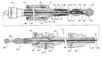
- FIG. 1shows a part cross sectional view of an embodiment of an deployment device according to this invention for deploying a prosthesis into the thoracic aorta;
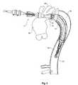
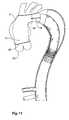
- FIG. 2shows a schematic view of the thoracic aorta showing regions of aneurysm to be treated according to the present invention
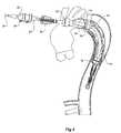
- FIG. 3shows a first stage in the deployment of the prosthesis into the descending aorta
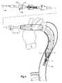
- FIG. 4shows the next stage in the deployment
- FIG. 5shows the next stage of deployment where the portion of the prosthesis folded back inside itself is withdrawn
- FIG. 6shows the next stage in which the distal end of the prosthesis is partially released
- FIG. 7shows the next stage in the deployment where the distal end of the prosthesis is fully released
- FIG. 8shows a still further stage with withdrawal of the trigger wire retaining the stented portion of the prosthesis
- FIG. 9shows withdrawal of the nose portion of the deployment device
- FIG. 10shows removal of the deployment device
- FIG. 11shows the final suturing in of the prosthesis according to this invention around the aortic valve and the branching arteries.
- the deployment device 1has a prosthesis generally shown as 3 mounted onto it.
- the prosthesis 3is of generally corrugated form and formed from a biocompatible material.
- the distal end 5 of the prosthesishas an internal zig-zag stent 7 and a distally extending external stent 9 .
- the external stent 9has barbs 11 on it but when the prosthesis 3 is loaded onto the deployment device 1 the barbs 11 are contained within nose cone 22 of the deployment device as will be discussed below.
- a central portion 13 of the prosthesis 3extends back over the deployment device and is folded back inside itself until it is mounted at its proximal end 15 to a fixing boss 32 of the deployment device 1 by means of knotted suture 16 as will be discussed later.
- the deployment device 1includes a central guide wire catheter 20 which extends from a nose cone 22 at a distal end of the deployment device to a nose cone actuator 24 at a proximal end of the device.
- the central catheter 20is sufficiently flexible to be guided down the descending aorta as will be discussed later. In use, the nose cone actuator 24 is intended to remain outside the patient.
- a deployment catheter 26Surrounding the central catheter 20 is a deployment catheter 26 .
- the deployment catheter 26can be moved longitudinally with respect to the central catheter 20 and can be locked into position with respect to the central catheter by means of pin vice arrangement 28 at the proximal end of a handle 25 .
- the pin vice arrangement 28 and handle 25is also intended, in use, to remain outside a patient.
- the handle 25is at the proximal end of the deployment catheter 26 .
- a manipulator sheath 30Surrounding the deployment catheter 26 is a manipulator sheath 30 which extends from a proximal prosthesis end 15 fixing boss 32 to a proximal end manipulator 34 .
- the proximal end manipulator 34is intended to remain outside a patient.
- the proximal end manipulator 34includes a haemostatic seal 36 which engages against the outside of the deployment catheter 26 .
- the haemostatic seal 36is intended to prevent blood loss between the deployment catheter and the manipulator sheath but also provides frictional engagement and feel between these components.
- the nose cone 22includes a recess 40 which provides a capsule into which the external stent 9 of the prosthesis is received and which encloses the barbs 11 on the external stent 9 during deployment.
- the nose cone actuator 24can be moved distally to in turn move the nose cone 22 distally to release the external stent 9 as will be discussed later.
- a first trigger wire arrangementis provided to retain the external stent within the nose cone and to hold the internal zig-zag stent in a compressed condition during deployment.
- the first trigger wire 44extends from a trigger wire boss 42 which is mounted onto the handle 25 at the proximal end of the deployment catheter and which in use remains external of the patient to the distal end of the deployment device between the central catheter 20 and the deployment catheter 26 in the lumen of the deployment catheter.
- the first trigger wire 44extends out through a side aperture 46 in the deployment catheter to engage and to retain the internal stent 7 in a retracted condition. This may be done with the assistance of a suture or mooring loop 44 which holds the internal stent in a contracted condition. The suture or mooring loop 44 may remain with the internal stent after deployment or remain with the deployment device.
- the trigger wire 44engages the internal stent it re-enters a further aperture 48 in the deployment catheter and then extends further distally out of the distal end of the prosthesis 5 and into an aperture 41 in the nose cone 22 to exit the nose cone 22 and re-enter through aperture 43 to engage with the external stent 9 and then exit out a further aperture 52 in the nose cone.
- the aperture 52retains the distal end of the trigger wire and prevents it fouling with other objects during deployment.
- the trigger boss 42can be completely withdrawn which in turns pulls the trigger wire 44 so that it no longer engages the external stent 9 and the internal stent 7 .
- the external stentis still retained within the recess 40 in the nose cone 22 until such time as this is moved distally as will be discussed below and with respect to the drawings showing the various stages of deployment.
- a second trigger wire arrangementis provided to retain the internal stent 7 with respect to the deployment catheter during movement of the nose cone 22 .
- the trigger wire 31extends from a trigger wire boss 33 which in use remains external of the patient to the distal end of the deployment device between the central catheter 20 and the deployment catheter 26 in the lumen of the deployment catheter. Towards the distal end of the deployment, the catheter trigger wire 31 extends out through a side aperture 35 in the deployment catheter to engage and to retain the internal stent 7 .
- the trigger wire boss 33can be completely withdrawn which in turns pulls the trigger wire 31 so that it no longer engages the external stent as will be discussed with respect to the drawings showing the various stages of deployment.
- a proximal retainer 45 for the prosthesisis mounted coaxially on the manipulator sheath 30 and has a grip 47 .
- the proximal end 51 of the folded prosthesis 13is retained onto the proximal retainer 45 by means of a loop of suture 49 .
- the proximal retentionallows for control of the proximal end of the sheath during deployment as will be discussed later.
- FIG. 2shows a schematic view of the thoracic arch region of an aorta of a patient.
- the aortaextends from an aortic valve 60 of a patient via the ascending aorta 62 to the thoracic arch 64 before proceeding down the descending aorta 66 .
- An aneurysm 68has been depicted in the ascending aorta as well as adjacent the thoracic arch 64 in the descending aorta.
- major arteries, the innominate artery 69 , the left common carotid artery 70 and the subclavian artery 72exit from the aorta. Any deployment of a prosthesis into the aorta must allow blood to still get to these arteries.
- an incision 75has been made in the side of the thoracic arch 64 of the aorta and the deployment device 1 with the prosthesis mounted onto it has been inserted so that it extends down the descending aorta 66 .
- the deployment devicehas been deployed to the extent that the nose cone 22 is well past the aneurysm region 68 .
- the central portion of the prosthesis 13extends back along the deployment device 1 so that it is still visible in the incision 75 .
- the central portion 13is then fastened circumferentially to the aortic arch as is shown in FIG. 4 just distally of the subclavian artery 72 .
- the prosthesisis sutured or stapled or otherwise fastened completely around its circumference at this point to the wall of the aorta.
- the proximal retainer 45assists in holding the proximal end 51 of the folded prosthesis during this fastening.
- the prosthesiscan then be straightened out by pulling on the proximal end manipulator 34 while holding the handle 25 stationary so that the manipulator sheath 30 withdraws the fixing boss 32 until the position shown in FIG. 5 is attained.
- trigger wire boss 42is completely removed from the handle 25 by releasing the thumb screw 54 and withdrawing the trigger wire boss 42 over the nose cone actuator 24 .
- trigger wire 44is removed completely from the nose cone 22 and from retaining the external and internal stents 9 , 7 .
- FIG. 6it will be seen that the internal stent 7 has partially expanded but that the external stent 9 is still retained within the nose cone 22 .
- the pin vice 28is released and the nose cone activator 24 advanced distally so that by moving the catheter 20 fixed to the activator 24 the nose cone 22 moves distally and releases the external stent 9 from the recess 40 which enables the external stent 9 to expand to the wall of the descending aorta 66 and the barbs 11 to engage into the wall of the aorta to hold the distal ends of the prosthesis 3 in the descending aorta.
- the internal stent 7is retained by the trigger wire 31 . This prevents the prosthesis moving distally while the nose cone is being moved distally.
- trigger wire 31is removed completely and the internal stent 7 can fully expand to engage the wall of the aorta. This is shown in FIG. 8 .
- the nose cone 22 and catheter 20 and deployment device 1are then retracted towards the fixing boss 32 as shown in FIG. 9 leaving part of the prosthesis deployed in the descending aorta from the central portion 13 sutured into the aortic arch down to the distal end 5 of the prosthesis 3 retained by the internal stent 7 and external stent 9 and barbs 11 .
- the proximal end 15 of the prosthesis 3is fed back into the incision 75 in the aortic arch and directed down the ascending aorta towards the aortic valve 60 .
- the proximal end of the graft 15is then sutured circumferentially at 80 around the aortic valve 60 so that blood can flow out of the valve and into the prosthesis end 15 .
- an incision 82is made in the side of the prosthesis 3 and the prosthesis 3 is sutured around the branch arteries so the blood can flow into them as well.
- the incision 75is then closed up as shown in FIG. 11 and the chest cavity closed.
Landscapes
- Health & Medical Sciences (AREA)
- Engineering & Computer Science (AREA)
- Biomedical Technology (AREA)
- Life Sciences & Earth Sciences (AREA)
- General Health & Medical Sciences (AREA)
- Transplantation (AREA)
- Cardiology (AREA)
- Veterinary Medicine (AREA)
- Heart & Thoracic Surgery (AREA)
- Vascular Medicine (AREA)
- Public Health (AREA)
- Animal Behavior & Ethology (AREA)
- Oral & Maxillofacial Surgery (AREA)
- Gastroenterology & Hepatology (AREA)
- Pulmonology (AREA)
- Prostheses (AREA)
- Medicines Containing Plant Substances (AREA)
- Electrotherapy Devices (AREA)
- Soil Working Implements (AREA)
- Harvester Elements (AREA)
Abstract
Description
Claims (7)
Priority Applications (1)
| Application Number | Priority Date | Filing Date | Title |
|---|---|---|---|
| US10/726,962US7488344B2 (en) | 2002-12-04 | 2003-12-03 | Device and method for treating thoracic aorta |
Applications Claiming Priority (2)
| Application Number | Priority Date | Filing Date | Title |
|---|---|---|---|
| US43082102P | 2002-12-04 | 2002-12-04 | |
| US10/726,962US7488344B2 (en) | 2002-12-04 | 2003-12-03 | Device and method for treating thoracic aorta |
Publications (2)
| Publication Number | Publication Date |
|---|---|
| US20040193244A1 US20040193244A1 (en) | 2004-09-30 |
| US7488344B2true US7488344B2 (en) | 2009-02-10 |
Family
ID=32469536
Family Applications (1)
| Application Number | Title | Priority Date | Filing Date |
|---|---|---|---|
| US10/726,962Active2026-02-07US7488344B2 (en) | 2002-12-04 | 2003-12-03 | Device and method for treating thoracic aorta |
Country Status (8)
| Country | Link |
|---|---|
| US (1) | US7488344B2 (en) |
| EP (1) | EP1567092B1 (en) |
| AT (1) | ATE421301T1 (en) |
| AU (1) | AU2003293267B2 (en) |
| CA (1) | CA2505418C (en) |
| DE (1) | DE60325999D1 (en) |
| DK (1) | DK1567092T3 (en) |
| WO (1) | WO2004049977A1 (en) |
Cited By (23)
| Publication number | Priority date | Publication date | Assignee | Title |
|---|---|---|---|---|
| US20060009858A1 (en)* | 2004-07-09 | 2006-01-12 | Gi Dynamics, Inc. | Methods and devices for placing a gastrointestinal sleeve |
| US20080109058A1 (en)* | 2005-06-01 | 2008-05-08 | Cook Incorporated | Intraoperative Anastomosis Method |
| US20090287145A1 (en)* | 2008-05-15 | 2009-11-19 | Altura Interventional, Inc. | Devices and methods for treatment of abdominal aortic aneurysms |
| US20110130819A1 (en)* | 2009-12-01 | 2011-06-02 | Altura Medical, Inc. | Modular endograft devices and associated systems and methods |
| US20120172968A1 (en)* | 2006-04-27 | 2012-07-05 | William A. Cook Australila Pty. Ltd. | Controlled sequential deployment |
| EP2574306A1 (en) | 2011-09-27 | 2013-04-03 | Cook Medical Technologies LLC | Endoluminal prosthesis with steerable branch |
| EP2606853A1 (en) | 2011-12-22 | 2013-06-26 | Cook Medical Technologies LLC | Hybrid aortic arch replacement |
| US8663310B2 (en) | 2010-12-15 | 2014-03-04 | Cook Medical Technologies Llc | Hybrid type A dissection device |
| US8858613B2 (en) | 2010-09-20 | 2014-10-14 | Altura Medical, Inc. | Stent graft delivery systems and associated methods |
| US9155609B2 (en) | 2002-12-02 | 2015-10-13 | Gi Dynamics, Inc. | Bariatric sleeve |
| US9237944B2 (en) | 2003-12-09 | 2016-01-19 | Gi Dynamics, Inc. | Intestinal sleeve |
| US9463104B2 (en) | 2013-06-07 | 2016-10-11 | Cedars-Sinai Medical Center | Vascular graft device placement methods |
| US9737426B2 (en) | 2013-03-15 | 2017-08-22 | Altura Medical, Inc. | Endograft device delivery systems and associated methods |
| US9901474B2 (en) | 2002-12-02 | 2018-02-27 | Gi Dynamics, Inc. | Anti-obesity devices |
| EP3315092A2 (en) | 2016-10-27 | 2018-05-02 | Cook Medical Technologies LLC | Prosthesis with branched portion |
| US10285833B2 (en) | 2012-08-10 | 2019-05-14 | Lombard Medical Limited | Stent delivery systems and associated methods |
| US10383752B2 (en) | 2015-01-11 | 2019-08-20 | Ascyrus Medical, Llc | Hybrid device for surgical aortic repair configured for adaptability of organs of various anatomical characteristics and method of using the same |
| US10470871B2 (en) | 2001-12-20 | 2019-11-12 | Trivascular, Inc. | Advanced endovascular graft |
| US10610393B2 (en) | 2016-03-24 | 2020-04-07 | Cook Medical Technologies Llc | Wire retention and release mechanisms |
| US10888414B2 (en) | 2019-03-20 | 2021-01-12 | inQB8 Medical Technologies, LLC | Aortic dissection implant |
| US11259911B2 (en) | 2015-06-18 | 2022-03-01 | Ascyrus Medical, Llc | Branched aortic graft and method of using the same |
| US11389289B2 (en) | 2017-03-24 | 2022-07-19 | Ascyrus Medical, Llc | Multi-spiral self-expanding stent and methods of making and using the same |
| US11628056B2 (en) | 2016-11-22 | 2023-04-18 | Cook Medical Technologies Llc | Graft for treating the distal aortic arch and descending aorta in type a patients |
Families Citing this family (58)
| Publication number | Priority date | Publication date | Assignee | Title |
|---|---|---|---|---|
| US6254564B1 (en) | 1998-09-10 | 2001-07-03 | Percardia, Inc. | Left ventricular conduit with blood vessel graft |
| DE10010073B4 (en) | 2000-02-28 | 2005-12-22 | Fraunhofer-Gesellschaft zur Förderung der angewandten Forschung e.V. | Anchoring for implantable heart valve prostheses |
| DE10010074B4 (en) | 2000-02-28 | 2005-04-14 | Fraunhofer-Gesellschaft zur Förderung der angewandten Forschung e.V. | Device for fastening and anchoring heart valve prostheses |
| FR2828263B1 (en) | 2001-08-03 | 2007-05-11 | Philipp Bonhoeffer | DEVICE FOR IMPLANTATION OF AN IMPLANT AND METHOD FOR IMPLANTATION OF THE DEVICE |
| US20070198078A1 (en)* | 2003-09-03 | 2007-08-23 | Bolton Medical, Inc. | Delivery system and method for self-centering a Proximal end of a stent graft |
| US11596537B2 (en) | 2003-09-03 | 2023-03-07 | Bolton Medical, Inc. | Delivery system and method for self-centering a proximal end of a stent graft |
| US20080264102A1 (en)* | 2004-02-23 | 2008-10-30 | Bolton Medical, Inc. | Sheath Capture Device for Stent Graft Delivery System and Method for Operating Same |
| US11259945B2 (en) | 2003-09-03 | 2022-03-01 | Bolton Medical, Inc. | Dual capture device for stent graft delivery system and method for capturing a stent graft |
| US8500792B2 (en) | 2003-09-03 | 2013-08-06 | Bolton Medical, Inc. | Dual capture device for stent graft delivery system and method for capturing a stent graft |
| US7763063B2 (en) | 2003-09-03 | 2010-07-27 | Bolton Medical, Inc. | Self-aligning stent graft delivery system, kit, and method |
| US9198786B2 (en)* | 2003-09-03 | 2015-12-01 | Bolton Medical, Inc. | Lumen repair device with capture structure |
| US8292943B2 (en) | 2003-09-03 | 2012-10-23 | Bolton Medical, Inc. | Stent graft with longitudinal support member |
| EP1791498B1 (en)* | 2004-09-22 | 2018-02-28 | Cook Medical Technologies, LLC | Stent graft with integral side arm |
| DE102005003632A1 (en) | 2005-01-20 | 2006-08-17 | Fraunhofer-Gesellschaft zur Förderung der angewandten Forschung e.V. | Catheter for the transvascular implantation of heart valve prostheses |
| US20060276883A1 (en)* | 2005-06-01 | 2006-12-07 | Cook Incorporated | Tapered and distally stented elephant trunk stent graft |
| DE102005051849B4 (en) | 2005-10-28 | 2010-01-21 | JenaValve Technology Inc., Wilmington | Device for implantation and attachment of heart valve prostheses |
| DE102005052628B4 (en) | 2005-11-04 | 2014-06-05 | Jenavalve Technology Inc. | Self-expanding, flexible wire mesh with integrated valvular prosthesis for the transvascular heart valve replacement and a system with such a device and a delivery catheter |
| US20070213813A1 (en) | 2005-12-22 | 2007-09-13 | Symetis Sa | Stent-valves for valve replacement and associated methods and systems for surgery |
| ES2382364T3 (en)* | 2006-09-28 | 2012-06-07 | St George Medical Inc | Thoracic aortic aneurysm repair device. |
| US7896915B2 (en) | 2007-04-13 | 2011-03-01 | Jenavalve Technology, Inc. | Medical device for treating a heart valve insufficiency |
| US9138315B2 (en) | 2007-04-13 | 2015-09-22 | Jenavalve Technology Gmbh | Medical device for treating a heart valve insufficiency or stenosis |
| EP2659861B1 (en) | 2007-05-15 | 2019-03-13 | JenaValve Technology, Inc. | Handle for manipulating a catheter tip, catheter system and medical insertion system for inserting a self-expandable heart valve stent |
| EP2210248B1 (en)* | 2007-11-13 | 2016-04-20 | Cook Medical Technologies LLC | Intraluminal bypass prosthesis |
| US8465540B2 (en) | 2008-02-26 | 2013-06-18 | Jenavalve Technology, Inc. | Stent for the positioning and anchoring of a valvular prosthesis |
| US9044318B2 (en) | 2008-02-26 | 2015-06-02 | Jenavalve Technology Gmbh | Stent for the positioning and anchoring of a valvular prosthesis |
| US9168130B2 (en) | 2008-02-26 | 2015-10-27 | Jenavalve Technology Gmbh | Stent for the positioning and anchoring of a valvular prosthesis in an implantation site in the heart of a patient |
| US8398704B2 (en) | 2008-02-26 | 2013-03-19 | Jenavalve Technology, Inc. | Stent for the positioning and anchoring of a valvular prosthesis in an implantation site in the heart of a patient |
| US8317858B2 (en) | 2008-02-26 | 2012-11-27 | Jenavalve Technology, Inc. | Stent for the positioning and anchoring of a valvular prosthesis in an implantation site in the heart of a patient |
| BR112012021347A2 (en) | 2008-02-26 | 2019-09-24 | Jenavalve Tecnology Inc | stent for positioning and anchoring a valve prosthesis at an implantation site in a patient's heart |
| CN102076281B (en) | 2008-06-30 | 2014-11-05 | 波顿医疗公司 | Systems and methods for abdominal aortic aneurysm |
| US11376114B2 (en) | 2008-10-31 | 2022-07-05 | Cook Medical Technologies Llc | Introducer for deploying a stent graft in a curved lumen and stent graft therefor |
| GB2464977B (en) | 2008-10-31 | 2010-11-03 | William Cook Europe As | Introducer for deploying a stent graft in a curved lumen and stent graft therefor |
| EP3284447B1 (en) | 2009-03-13 | 2020-05-20 | Bolton Medical Inc. | System for deploying an endoluminal prosthesis at a surgical site |
| US20100292779A1 (en) | 2009-05-15 | 2010-11-18 | Helmut Straubinger | Device for compressing a stent and a system as well as a method for loading a stent into a medical delivery system |
| WO2011059707A1 (en)* | 2009-10-29 | 2011-05-19 | William A. Cook Australia Pty. Ltd. | Stent delivery system with nitinol trigger wire |
| US10856978B2 (en) | 2010-05-20 | 2020-12-08 | Jenavalve Technology, Inc. | Catheter system |
| US11278406B2 (en) | 2010-05-20 | 2022-03-22 | Jenavalve Technology, Inc. | Catheter system for introducing an expandable heart valve stent into the body of a patient, insertion system with a catheter system and medical device for treatment of a heart valve defect |
| WO2011147849A1 (en) | 2010-05-25 | 2011-12-01 | Jenavalve Technology Inc. | Prosthetic heart valve and transcatheter delivered endoprosthesis comprising a prosthetic heart valve and a stent |
| US9510947B2 (en) | 2011-10-21 | 2016-12-06 | Jenavalve Technology, Inc. | Catheter system for introducing an expandable heart valve stent into the body of a patient |
| EP2846743B1 (en) | 2012-04-12 | 2016-12-14 | Bolton Medical Inc. | Vascular prosthetic delivery device |
| EP2849678B1 (en) | 2012-05-16 | 2022-08-10 | JenaValve Technology, Inc. | Catheter delivery system for introducing an expandable heart valve prosthesis and medical device for the treatment of a heart valve defect |
| US9433521B2 (en) | 2012-11-27 | 2016-09-06 | Medtronic, Inc. | Distal tip for a delivery catheter |
| US9622893B2 (en) | 2012-12-20 | 2017-04-18 | Cook Medical Technologies Llc | Apparatus and method for improved deployment of endovascular grafts |
| US9439751B2 (en) | 2013-03-15 | 2016-09-13 | Bolton Medical, Inc. | Hemostasis valve and delivery systems |
| CN105491978A (en) | 2013-08-30 | 2016-04-13 | 耶拿阀门科技股份有限公司 | Radially collapsible frame for a prosthetic valve and method for manufacturing such a frame |
| CN103720529B (en)* | 2013-12-30 | 2017-02-08 | 先健科技(深圳)有限公司 | Arcus aortae intraoperative stent and method for manufacturing stent |
| EP3270825B1 (en) | 2015-03-20 | 2020-04-22 | JenaValve Technology, Inc. | Heart valve prosthesis delivery system |
| US10709555B2 (en) | 2015-05-01 | 2020-07-14 | Jenavalve Technology, Inc. | Device and method with reduced pacemaker rate in heart valve replacement |
| WO2017195125A1 (en) | 2016-05-13 | 2017-11-16 | Jenavalve Technology, Inc. | Heart valve prosthesis delivery system and method for delivery of heart valve prosthesis with introducer sheath and loading system |
| WO2018138658A1 (en) | 2017-01-27 | 2018-08-02 | Jenavalve Technology, Inc. | Heart valve mimicry |
| US10709541B2 (en) | 2017-04-28 | 2020-07-14 | Cook Medical Technologies Llc | Systems and methods for adjusting the diameter of an endoluminal prosthesis and an endoluminal prosthesis configured for the same |
| EP3672522A1 (en) | 2017-11-16 | 2020-07-01 | Vicchio, Mariano | Vascular prosthesis for use in the treatment of arterial diseases |
| JP7114738B2 (en)* | 2018-04-26 | 2022-08-08 | ボストン サイエンティフィック サイムド,インコーポレイテッド | Medical device with connecting member |
| EP4585192A3 (en) | 2020-06-24 | 2025-10-15 | Bolton Medical, Inc. | Anti-backspin component for vascular prosthesis delivery device |
| GB2605559B (en) | 2021-01-07 | 2023-04-05 | Cook Medical Technologies Llc | Stent graft |
| US12016777B2 (en) | 2021-01-26 | 2024-06-25 | Boston Scientific Scimed, Inc. | Medical device including attachable components |
| US12396852B2 (en) | 2021-01-26 | 2025-08-26 | Boston Scientific Scimed, Inc. | Medical device including attachable components |
| WO2024102411A1 (en) | 2022-11-09 | 2024-05-16 | Jenavalve Technology, Inc. | Catheter system for sequential deployment of an expandable implant |
Citations (6)
| Publication number | Priority date | Publication date | Assignee | Title |
|---|---|---|---|---|
| US20020151953A1 (en)* | 2001-04-11 | 2002-10-17 | Trivascular, Inc. | Delivery system and method for bifurcated endovascular graft |
| US6773457B2 (en)* | 2001-03-27 | 2004-08-10 | William Cook Europe Aps | Aortic graft device |
| US6939370B2 (en)* | 2002-06-28 | 2005-09-06 | Cook Incorporated | Thoracic aortic stent graft deployment device |
| US7074235B1 (en)* | 1999-10-16 | 2006-07-11 | Sumit Roy | Low-profile, non-stented prosthesis for transluminal implantation |
| US7147656B2 (en)* | 2001-12-03 | 2006-12-12 | Xtent, Inc. | Apparatus and methods for delivery of braided prostheses |
| US7175652B2 (en)* | 2002-08-20 | 2007-02-13 | Cook Incorporated | Stent graft with improved proximal end |
Family Cites Families (2)
| Publication number | Priority date | Publication date | Assignee | Title |
|---|---|---|---|---|
| DE20115706U1 (en)* | 2001-09-25 | 2001-12-13 | Curative Ag | Arrangement for implantation in an aorta |
| EP1336392A1 (en)* | 2002-02-14 | 2003-08-20 | John S. Geis | Body vessel support and catheter system |
- 2003
- 2003-12-03EPEP03790266Apatent/EP1567092B1/ennot_activeExpired - Lifetime
- 2003-12-03USUS10/726,962patent/US7488344B2/enactiveActive
- 2003-12-03WOPCT/US2003/038386patent/WO2004049977A1/ennot_activeApplication Discontinuation
- 2003-12-03DEDE60325999Tpatent/DE60325999D1/ennot_activeExpired - Lifetime
- 2003-12-03DKDK03790266Tpatent/DK1567092T3/enactive
- 2003-12-03ATAT03790266Tpatent/ATE421301T1/ennot_activeIP Right Cessation
- 2003-12-03CACA2505418Apatent/CA2505418C/ennot_activeExpired - Lifetime
- 2003-12-03AUAU2003293267Apatent/AU2003293267B2/ennot_activeExpired
Patent Citations (6)
| Publication number | Priority date | Publication date | Assignee | Title |
|---|---|---|---|---|
| US7074235B1 (en)* | 1999-10-16 | 2006-07-11 | Sumit Roy | Low-profile, non-stented prosthesis for transluminal implantation |
| US6773457B2 (en)* | 2001-03-27 | 2004-08-10 | William Cook Europe Aps | Aortic graft device |
| US20020151953A1 (en)* | 2001-04-11 | 2002-10-17 | Trivascular, Inc. | Delivery system and method for bifurcated endovascular graft |
| US7147656B2 (en)* | 2001-12-03 | 2006-12-12 | Xtent, Inc. | Apparatus and methods for delivery of braided prostheses |
| US6939370B2 (en)* | 2002-06-28 | 2005-09-06 | Cook Incorporated | Thoracic aortic stent graft deployment device |
| US7175652B2 (en)* | 2002-08-20 | 2007-02-13 | Cook Incorporated | Stent graft with improved proximal end |
Cited By (42)
| Publication number | Priority date | Publication date | Assignee | Title |
|---|---|---|---|---|
| US11439497B2 (en) | 2001-12-20 | 2022-09-13 | Trivascular, Inc. | Advanced endovascular graft |
| US10470871B2 (en) | 2001-12-20 | 2019-11-12 | Trivascular, Inc. | Advanced endovascular graft |
| US9901474B2 (en) | 2002-12-02 | 2018-02-27 | Gi Dynamics, Inc. | Anti-obesity devices |
| US9155609B2 (en) | 2002-12-02 | 2015-10-13 | Gi Dynamics, Inc. | Bariatric sleeve |
| US9750596B2 (en) | 2002-12-02 | 2017-09-05 | Gi Dynamics, Inc. | Bariatric sleeve |
| US9744061B2 (en) | 2003-12-09 | 2017-08-29 | Gi Dynamics, Inc. | Intestinal sleeve |
| US9237944B2 (en) | 2003-12-09 | 2016-01-19 | Gi Dynamics, Inc. | Intestinal sleeve |
| US20060009858A1 (en)* | 2004-07-09 | 2006-01-12 | Gi Dynamics, Inc. | Methods and devices for placing a gastrointestinal sleeve |
| US7837643B2 (en)* | 2004-07-09 | 2010-11-23 | Gi Dynamics, Inc. | Methods and devices for placing a gastrointestinal sleeve |
| US20080109058A1 (en)* | 2005-06-01 | 2008-05-08 | Cook Incorporated | Intraoperative Anastomosis Method |
| US20120172968A1 (en)* | 2006-04-27 | 2012-07-05 | William A. Cook Australila Pty. Ltd. | Controlled sequential deployment |
| US8808349B2 (en)* | 2006-04-27 | 2014-08-19 | Cook Medical Technologies Llc | Controlled sequential deployment |
| US20090287145A1 (en)* | 2008-05-15 | 2009-11-19 | Altura Interventional, Inc. | Devices and methods for treatment of abdominal aortic aneurysms |
| US20110130820A1 (en)* | 2009-12-01 | 2011-06-02 | Altura Medical, Inc. | Modular endograft devices and associated systems and methods |
| US20110130825A1 (en)* | 2009-12-01 | 2011-06-02 | Altura Medical, Inc. | Modular endograft devices and associated systems and methods |
| US20110130824A1 (en)* | 2009-12-01 | 2011-06-02 | Altura Medical, Inc. | Modular endograft devices and associated systems and methods |
| US20110130819A1 (en)* | 2009-12-01 | 2011-06-02 | Altura Medical, Inc. | Modular endograft devices and associated systems and methods |
| US9572652B2 (en) | 2009-12-01 | 2017-02-21 | Altura Medical, Inc. | Modular endograft devices and associated systems and methods |
| US8858613B2 (en) | 2010-09-20 | 2014-10-14 | Altura Medical, Inc. | Stent graft delivery systems and associated methods |
| US8663310B2 (en) | 2010-12-15 | 2014-03-04 | Cook Medical Technologies Llc | Hybrid type A dissection device |
| EP3943046A1 (en) | 2011-09-27 | 2022-01-26 | Cook Medical Technologies LLC | Endoluminal prosthesis with steerable branch |
| EP2574306A1 (en) | 2011-09-27 | 2013-04-03 | Cook Medical Technologies LLC | Endoluminal prosthesis with steerable branch |
| EP2606853A1 (en) | 2011-12-22 | 2013-06-26 | Cook Medical Technologies LLC | Hybrid aortic arch replacement |
| US10285833B2 (en) | 2012-08-10 | 2019-05-14 | Lombard Medical Limited | Stent delivery systems and associated methods |
| US9737426B2 (en) | 2013-03-15 | 2017-08-22 | Altura Medical, Inc. | Endograft device delivery systems and associated methods |
| US9463104B2 (en) | 2013-06-07 | 2016-10-11 | Cedars-Sinai Medical Center | Vascular graft device placement methods |
| US12279981B2 (en) | 2015-01-11 | 2025-04-22 | Ascyrus Medical, LLC. | Hybrid device for surgical aortic repair configured for adaptability of organs of various anatomical characteristics and method of using the same |
| US10383752B2 (en) | 2015-01-11 | 2019-08-20 | Ascyrus Medical, Llc | Hybrid device for surgical aortic repair configured for adaptability of organs of various anatomical characteristics and method of using the same |
| US10624770B2 (en) | 2015-01-11 | 2020-04-21 | Ascyrus Medical, Llc | Hybrid device for surgical aortic repair configured for adaptability of organs of various anatomical characteristics and method of using the same |
| US12011346B2 (en) | 2015-06-18 | 2024-06-18 | Ascyrus Medical, Llc | Branched aortic graft and method of using the same |
| US11259911B2 (en) | 2015-06-18 | 2022-03-01 | Ascyrus Medical, Llc | Branched aortic graft and method of using the same |
| US10610393B2 (en) | 2016-03-24 | 2020-04-07 | Cook Medical Technologies Llc | Wire retention and release mechanisms |
| US10537419B2 (en) | 2016-10-27 | 2020-01-21 | Cook Medical Technologies Llc | Prosthesis with branched portion |
| US11464619B2 (en) | 2016-10-27 | 2022-10-11 | Cook Medical Technologies Llc | Prosthesis with branched portion |
| US11517418B2 (en) | 2016-10-27 | 2022-12-06 | Cook Medical Technologies Llc | Prosthesis with branched portion |
| EP4140445A1 (en) | 2016-10-27 | 2023-03-01 | Cook Medical Technologies LLC | Prosthesis with branched portion |
| US12239526B2 (en) | 2016-10-27 | 2025-03-04 | Cook Medical Technologies Llc | Prosthesis with branched portion |
| EP3315092A2 (en) | 2016-10-27 | 2018-05-02 | Cook Medical Technologies LLC | Prosthesis with branched portion |
| US11628056B2 (en) | 2016-11-22 | 2023-04-18 | Cook Medical Technologies Llc | Graft for treating the distal aortic arch and descending aorta in type a patients |
| US11389289B2 (en) | 2017-03-24 | 2022-07-19 | Ascyrus Medical, Llc | Multi-spiral self-expanding stent and methods of making and using the same |
| US12167958B2 (en) | 2017-03-24 | 2024-12-17 | Ascyrus Medical, Llc | Multi-spiral self-expanding stent and methods of making and using the same |
| US10888414B2 (en) | 2019-03-20 | 2021-01-12 | inQB8 Medical Technologies, LLC | Aortic dissection implant |
Also Published As
| Publication number | Publication date |
|---|---|
| EP1567092A1 (en) | 2005-08-31 |
| CA2505418A1 (en) | 2004-06-17 |
| DK1567092T3 (en) | 2009-04-14 |
| DE60325999D1 (en) | 2009-03-12 |
| AU2003293267B2 (en) | 2008-02-28 |
| CA2505418C (en) | 2012-02-28 |
| ATE421301T1 (en) | 2009-02-15 |
| WO2004049977A1 (en) | 2004-06-17 |
| AU2003293267A1 (en) | 2004-06-23 |
| US20040193244A1 (en) | 2004-09-30 |
| EP1567092B1 (en) | 2009-01-21 |
Similar Documents
| Publication | Publication Date | Title |
|---|---|---|
| US7488344B2 (en) | Device and method for treating thoracic aorta | |
| US11229537B2 (en) | Introducer for a side branch device | |
| US10201414B2 (en) | Introducer for a side branch device | |
| US7611529B2 (en) | Thoracic introducer | |
| EP2204141B1 (en) | Prosthesis deployment system retention device | |
| US9757263B2 (en) | Stent graft and introducer assembly | |
| EP1608293A1 (en) | Branch stent graft deployment and method |
Legal Events
| Date | Code | Title | Description |
|---|---|---|---|
| AS | Assignment | Owner name:BASF AKTIENGESELLSCHAFT, GERMANY Free format text:ASSIGNMENT OF ASSIGNORS INTEREST;ASSIGNORS:KELLER, HARALD;FRECHEN, THOMAS;SCHREPP, WOLFGANG;AND OTHERS;REEL/FRAME:014762/0535 Effective date:20030603 | |
| AS | Assignment | Owner name:WILLIAM A. COOK AUSTRALIA PTY. LTD., AUSTRALIA Free format text:ASSIGNMENT OF ASSIGNORS INTEREST;ASSIGNORS:HARTLEY, DAVID ERNEST;NIXON, IAN;MOSSOP, PETER JOHN;REEL/FRAME:019566/0309 Effective date:20050515 Owner name:COOK INCORPORATED, INDIANA Free format text:ASSIGNMENT OF ASSIGNORS INTEREST;ASSIGNORS:HARTLEY, DAVID ERNEST;NIXON, IAN;MOSSOP, PETER JOHN;REEL/FRAME:019566/0309 Effective date:20050515 | |
| STCF | Information on status: patent grant | Free format text:PATENTED CASE | |
| AS | Assignment | Owner name:COOK MEDICAL TECHNOLOGIES LLC, INDIANA Free format text:ASSIGNMENT OF ASSIGNORS INTEREST;ASSIGNORS:COOK INCORPORATED;WILSON-COOK MEDICAL INCORPORATED;VANCE PRODUCTS INCORPORATED;AND OTHERS;SIGNING DATES FROM 20110315 TO 20110322;REEL/FRAME:026287/0923 | |
| FPAY | Fee payment | Year of fee payment:4 | |
| FPAY | Fee payment | Year of fee payment:8 | |
| MAFP | Maintenance fee payment | Free format text:PAYMENT OF MAINTENANCE FEE, 12TH YEAR, LARGE ENTITY (ORIGINAL EVENT CODE: M1553); ENTITY STATUS OF PATENT OWNER: LARGE ENTITY Year of fee payment:12 | |
| AS | Assignment | Owner name:WILMINGTON TRUST, NATIONAL ASSOCIATION, AS COLLATERAL AGENT, DELAWARE Free format text:SECURITY INTEREST;ASSIGNOR:COOK MEDICAL TECHNOLOGIES LLC;REEL/FRAME:066700/0277 Effective date:20240227 |