US7487654B2 - Hydraulic tool with tactile feedback - Google Patents
Hydraulic tool with tactile feedbackDownload PDFInfo
- Publication number
- US7487654B2 US7487654B2US11/893,248US89324807AUS7487654B2US 7487654 B2US7487654 B2US 7487654B2US 89324807 AUS89324807 AUS 89324807AUS 7487654 B2US7487654 B2US 7487654B2
- Authority
- US
- United States
- Prior art keywords
- hydraulic
- tool
- user
- frame
- tactile feedback
- Prior art date
- Legal status (The legal status is an assumption and is not a legal conclusion. Google has not performed a legal analysis and makes no representation as to the accuracy of the status listed.)
- Active, expires
Links
Images


Classifications
- H—ELECTRICITY
- H01—ELECTRIC ELEMENTS
- H01R—ELECTRICALLY-CONDUCTIVE CONNECTIONS; STRUCTURAL ASSOCIATIONS OF A PLURALITY OF MUTUALLY-INSULATED ELECTRICAL CONNECTING ELEMENTS; COUPLING DEVICES; CURRENT COLLECTORS
- H01R43/00—Apparatus or processes specially adapted for manufacturing, assembling, maintaining, or repairing of line connectors or current collectors or for joining electric conductors
- H01R43/04—Apparatus or processes specially adapted for manufacturing, assembling, maintaining, or repairing of line connectors or current collectors or for joining electric conductors for forming connections by deformation, e.g. crimping tool
- H01R43/042—Hand tools for crimping
- H01R43/0427—Hand tools for crimping fluid actuated hand crimping tools
- B—PERFORMING OPERATIONS; TRANSPORTING
- B25—HAND TOOLS; PORTABLE POWER-DRIVEN TOOLS; MANIPULATORS
- B25B—TOOLS OR BENCH DEVICES NOT OTHERWISE PROVIDED FOR, FOR FASTENING, CONNECTING, DISENGAGING OR HOLDING
- B25B27/00—Hand tools, specially adapted for fitting together or separating parts or objects whether or not involving some deformation, not otherwise provided for
- B25B27/02—Hand tools, specially adapted for fitting together or separating parts or objects whether or not involving some deformation, not otherwise provided for for connecting objects by press fit or detaching same
- B25B27/10—Hand tools, specially adapted for fitting together or separating parts or objects whether or not involving some deformation, not otherwise provided for for connecting objects by press fit or detaching same inserting fittings into hoses
- Y—GENERAL TAGGING OF NEW TECHNOLOGICAL DEVELOPMENTS; GENERAL TAGGING OF CROSS-SECTIONAL TECHNOLOGIES SPANNING OVER SEVERAL SECTIONS OF THE IPC; TECHNICAL SUBJECTS COVERED BY FORMER USPC CROSS-REFERENCE ART COLLECTIONS [XRACs] AND DIGESTS
- Y10—TECHNICAL SUBJECTS COVERED BY FORMER USPC
- Y10T—TECHNICAL SUBJECTS COVERED BY FORMER US CLASSIFICATION
- Y10T29/00—Metal working
- Y10T29/53—Means to assemble or disassemble
- Y10T29/53087—Means to assemble or disassemble with signal, scale, illuminator, or optical viewer
- Y—GENERAL TAGGING OF NEW TECHNOLOGICAL DEVELOPMENTS; GENERAL TAGGING OF CROSS-SECTIONAL TECHNOLOGIES SPANNING OVER SEVERAL SECTIONS OF THE IPC; TECHNICAL SUBJECTS COVERED BY FORMER USPC CROSS-REFERENCE ART COLLECTIONS [XRACs] AND DIGESTS
- Y10—TECHNICAL SUBJECTS COVERED BY FORMER USPC
- Y10T—TECHNICAL SUBJECTS COVERED BY FORMER US CLASSIFICATION
- Y10T29/00—Metal working
- Y10T29/53—Means to assemble or disassemble
- Y10T29/5313—Means to assemble electrical device
- Y10T29/532—Conductor
- Y10T29/53209—Terminal or connector
- Y10T29/53213—Assembled to wire-type conductor
- Y10T29/53222—Means comprising hand-manipulatable implement
- Y10T29/53226—Fastening by deformation
Definitions
- the inventionrelates to a hydraulic tool and, more particularly, to a tool having a tactile feedback system.
- Battery powered hydraulic crimp toolsare known. Some battery powered hydraulic crimp tools have a system for generating an audible sound, such as a “pop” when a predetermined hydraulic pressure is reached. This can be used to signal a user that a good crimp has been obtained. This sound can be generated by a pressure relief valve opening.
- a hydraulic toolincluding a frame having a hydraulic fluid conduit system; a hydraulic pump coupled to the conduit system; and a tactile feedback system.
- the tactile feedback systemis coupled to the conduit system and is adapted to signal a user of an occurrence of a predetermined event.
- a hydraulic toolincluding a frame having a hydraulic fluid conduit system; a hydraulic pump coupled to the conduit system; and a signaling system.
- the signaling systemis coupled to the conduit system for signaling a user of an occurrence of a predetermined event.
- the signaling systemis adapted to generate at least two different signals to the user.
- a method for signaling a user of a hydraulic tool of an occurrence of a predetermined eventincluding allowing hydraulic fluid to pass through a valve of the tool upon the occurrence of the predetermined event; and generating a tactile sensation to a hand of the user holding the tool based upon the hydraulic fluid passing through the valve.
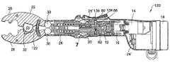
- FIG. 1is an elevational side view of a battery operated, hydraulic tool incorporating features of the invention
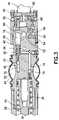
- FIG. 2is a side view of the tool shown in FIG. 1 with a cut away view of the housing;
- FIG. 3is a partial cross sectional view of some of the components of the tool shown in FIGS. 1 and 2 ;
- FIG. 4is a partial cross sectional view of some of the components of the tool shown in FIGS. 1 and 2 ;
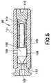
- FIG. 5is an enlarged cross sectional view of the relief valve shown in FIG. 4 ;
- FIG. 6is a cross sectional view of an alternate embodiment of the tool shown in FIG. 1-5 ;
- FIG. 7is an enlarged view of area A shown in FIG. 6 ;
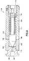
- FIG. 8is an enlarged cross sectional view of the relief valve shown in FIGS. 6-7 ;
- FIG. 9is a cross sectional view of an alternate embodiment of the relief valve shown in FIG. 8 .
- FIG. 1there is shown an elevational side view of a tool 10 incorporating features of the invention.
- a tool 10incorporating features of the invention.
- the inventionwill be described with reference to the exemplary embodiment shown in the drawings, it should be understood that the invention can be embodied in many alternate forms of embodiments.
- any suitable size, shape or type of elements or materialscould be used.
- the tool 10is a hand-held hydraulically operated, battery powered tool. However, features of the invention could be used in a non-battery operated tool.
- the tool 10is a crimping tool for crimping an electrical connector onto a conductor, such as an electrical cable for example.
- features of the inventioncould be used in any suitable type of hydraulically operated tool, such as a cutting tool for example.
- the tool 10generally comprises a pump 12 , a motor 14 , a transmission 16 connecting the motor to the pump, a battery 18 , a fluid reservoir 20 , a working head 22 , and a housing 24 .
- the tool 10has a user actuated control 25 , such as push buttons or a rocker switch for example.
- a user actuated control 25such as push buttons or a rocker switch for example.
- the working head 22in this embodiment, comprises a frame 26 , two jaws 28 and rollers 30 (see FIG. 4 ).
- any suitable type of working headcould be provided.
- the jaws 28are pivotably connected to the frame 26 at a pivot connection 32 .
- the front ends of the jawsare adapted to removably receive crimping dies.
- the working headcould be a die-less crimping head.
- the rollers 30are located against the rear ends of the jaws 28 ; and can be pushed between the rear ends of the jaws.
- the pivot connection 32could be assisted by an extension spring in jaw holes (see FIG. 6 for example) to bias the jaws 28 towards an open position when the ram 34 (see FIG. 4 ) is in a rearward position.
- the pump 12could comprise any suitable pump.
- the pumpis a wobble plate pump such as described in U.S. patent application Ser. No. 11/429,039 which is hereby incorporated by reference in its entirety.
- the pump 12comprises a frame 36 .
- the frame 36has a front end which forms a ram cylinder 38 .
- the ram 34is located in the ram cylinder 38 and biased towards a rearward position by a ram spring 40 .
- the front end of the ram 34is located against the rollers 30 .
- the ram 34can be moved forward by hydraulic fluid to move the rollers 30 forward and, thus, spread the rear ends of the jaws 28 apart. This causes the front ends of the jaws to be moved towards each other.
- the frame 36forms hydraulic conduits from a piston channel 42 to the rear end of the ram at the ram cylinder 38 .
- Various check valves and a release and/or relief valveare also preferably located in the hydraulic conduits.
- An exterior side of the frame 36also forms part of the reservoir 20 .
- a bladder 44is attached at an annular recess 46 of the frame 36 to form the reservoir 20 .
- any suitable type of hydraulic fluid reservoir or hydraulic fluid supplycould be provided.
- the pump 12comprises a piston pump member 48 located in the piston channel 42 .
- the piston pump member 48extends out of the rear end of the frame 36 and is biased outward by a spring 50 .
- the piston member 48is arranged in the piston channel 42 for reciprocating forward and backward movement. As the piston member 48 moves rearward it draws hydraulic fluid into the piston chamber 42 from the reservoir 20 through the conduit 70 and past check valve 72 . As the piston member 48 moves forward, it pushes that hydraulic fluid towards the ram cylinder 38 through conduit 74 and past check valve 76 .
- the rear end of the frame 36comprises a pivot member hole 52 and at least one spring hole 54 .
- a pivot member 56is pivotably located in the hole 52 .
- the pivot member 56is a ball.
- a spring 58such as a coil spring, is located in each of the holes 54 . In this embodiment only one coil spring 58 is provided. However, in alternate embodiments two to five or more coil springs could be provided.
- the spring 58is located on an opposite side of the rear end of the frame 36 from the piston member 48 with the pivot member 56 therebetween.
- the transmission 16generally comprises the wobble plate 60 , a transmission case 62 , a bevel disk 64 and a gearbox 66 .
- the gearbox 66is connected to an output shaft of the motor 14 .
- the bevel disk 64is connected to an output shaft 68 of the gearbox 66 .
- the front end of the bevel disk 64has an angled front face. The face is angled relative to the center axis. The front end also comprises a counter balance pocket.
- the user interface or control 25includes an activation lever 94 pivotably connected to the frame 36 or the housing 24 .
- the lever 94is preferably biased by a spring in an outward position.
- any suitable type of user activation controlcould be provided.
- the tool 10includes a hydraulic fluid release system 78 .
- the release system 78generally comprises a drain pin 80 , a drain valve 82 , and a retract lever 84 .
- the retract lever 84is part of the user interface 25 .
- the release system 78uses these members in combination with the conduits 86 , 88 , 90 , 92 to release hydraulic fluid from the ram cylinder 38 back into the reservoir 20 .
- the drain valve 82has a spring for biasing the drain valve in a closed position.
- the Drain pin 80has an end which extends out of the frame 36 .
- the retract lever 84is pivotably connected to the frame 36 or the housing 24 .
- the lever 84may be biased by a spring against the outer end of the drain pin 80 .
- the lever 84is preferably biased on the housing 24 away from the drain pin 80 .
- the spring of the drain valve 82is stronger than the spring of the lever 84 .
- the levercan move both inward and outward from a home position shown in FIG. 4 .
- the lever 84can be depressed by a hand or finger of a user to move the drain pin 80 inward. This can unseat the drain valve 82 and, therefore, open the drain valve 82 to allow release of hydraulic fluid from the ram cylinder 38 back into the reservoir 20 . This allows the ram 34 to retract rearward, which causes the crimp jaws to open.
- the tool 10also includes a hydraulic fluid relief system 96 .
- the relief system 96generally comprises a relief valve 98 connected to the conduit system of the frame 36 between the ram cylinder 38 and the reservoir 20 .
- the relief valve 98is mounted in the conduit 90 proximate the conduit 92 .
- the relief valve 98generally comprises a valve body 100 , a valve cone 102 and a spring 104 .
- the valve body 100includes an inlet port 106 , outlet ports 108 , an adjusting screw 110 , and a reduced outer diameter section 111 .
- the valve cone 102is movably located in the valve body.
- the spring 104biases the valve cone 102 into sealing contact with the valve seat 112 formed at the inlet port 106 .
- the front of the valve cone 102is unseated from the valve seat 112 (due to hydraulic pressure at the inlet port 106 ) and hydraulic fluid is allowed to flow from the ram cylinder 38 , through the inlet port 106 , out the outlet port 108 and back to the reservoir 20 through conduit 92 .
- the relief valve 98remains closed.
- the relief valve 98may be adapted to generate an audible sound, such as a “pop” when it is opened.
- the relief valve 98could also be adapted to stay open until a predetermined lower hydraulic pressure is reached.
- the tool 10includes a second signaling system comprising a tactile feedback system.
- the tactile feedback systemcomprises the lever 84 , the drain pin 80 and the spring of the lever 84 .
- the tactile feedback systemis coupled to the conduit system and is adapted to signal a user of an occurrence of a predetermined event.
- the predetermined eventcould be the relief valve 98 being actuated or a predetermined hydraulic pressure being reached.
- the tactile feedback systemprovides tactile feedback to a hand of a user because the hand of the user will be contacting the lever 84 while the user is actuating the lever 94 . More specifically, when the valve 98 opens, some of the hydraulic fluid from the ram cylinder 38 will be pushed into the conduit 90 and push the drain pin 80 outward. The lever 84 will move outward with the spring of the lever 84 being deflected. When the valve 98 closes again, the spring of the lever 84 will move the lever back to its home position; back inward. Because of the reciprocating motion of the piston pump member 48 , the valve 98 can also be adapted to repeatedly open and close until the user stops actuating the lever 94 .
- the tactile feedback systemin this embodiment, will result in the lever 84 moving up and down in a type of vibratory effect on the user's hand; because the valve 98 will repeatedly open and close.
- the tactile feedbackmight not be vibratory.
- the tactile feedbackcould comprise only one tactile jolt type of signal. This could be accompanied by an audible “pop” as noted in the alternate embodiment described below.
- the toolhas a signaling system for signaling a user of an occurrence of a predetermined event and, more specifically, the signaling system is adapted to generate at least two different signals to the user.
- the two signalsinclude an auditory signal and a tactile signal.
- the signalscould include signals other than auditory and/or tactile, such as visual for example.
- only a tactile signaling systemmight be provided.
- the inventioncan relate to a battery powered hydraulic crimp tool.
- the inventioncan provide tactile feedback to the operator which indicates that a crimp is complete. Tactile feedback can be generated once the tool's predetermined relief valve set pressure has been achieved.
- the battery powered hydraulic crimp tool 10can be powered by a DC battery 18 coupled to a DC motor 14 which has an output shaft coupled to a gearbox 66 which also has an output shaft.
- a DC motor 14which has an output shaft coupled to a gearbox 66 which also has an output shaft.
- the bevel disk 64rotates which rotates on a thrust bearing and transfers rotary motion into linear motion of the wobble plate 60 .
- This activitycauses the pump 12 and pump spring to reciprocate.
- This reciprocating motionpumps hydraulic fluid from the reservoir 20 to the rearward section of the piston ram 34 .
- fluidis drawn from the reservoir 20 through the inlet check valve 72 .
- Pressure in the cylinder 38will rise to a predetermined relief valve set pressure.
- the relief valve 98is subjected to the same pressure as the cylinder 38 .
- the valve cone 102lifts off of the valve seat 112 and the cone 102 shuttles away from port 106 and allows fluid to pass through ports 108 back to the reservoir 20 .
- some fluidis permitted to pass over the valve body at a small diameter annular passageway 113 created by reduced outer diameter section 111 and into the conduit holding the drain pin 80 .
- the resulting hydraulic pressure in the conduit holding the drain pin 80is much lower than the hydraulic pressure in the cylinder 38 because the majority of escaping fluid is channeled to the reservoir 20 .
- the pressure that is applied to the drain pin 80happens over a very small period of time and causes the drain pin 80 to shuttle in a direction opposite to the drain valve 82 .
- the drain valve springis sized to be relatively stiff and the pressure pulse into conduit holding the drain pin 80 cannot provide enough force to move this spring; so the drain valve 82 remains closed.
- the drain pin 80shuttles in a direction opposite to the drain valve 82 , it bumps the retract trigger 84 which provides the tactile feedback to the operator that the predetermined relief valve pressure setting is achieved and, therefore, the crimp is complete.
- an operatorcan abort the crimp cycle at any point in time by simply activating the retract lever 84 and depress the drain pin 80 ; thus actuating the drain valve 82 .
- fluidis allowed to drain from the cylinder 38 through conduits, through the drain valve 82 , and through the annular passageway at the valve 98 back to the reservoir 20 . This activity will cause the crimp jaws to open.
- the pumpcould be provided outside of the tool.
- the toolcould be a pneumatic tool rather than a hydraulic tool.
- the toolis portably hand held, but in an alternate embodiment only a portion of the tool might be held by a hand of the user.
- the tool 120generally comprises a pump 12 , a motor 14 , a transmission 16 connecting the motor to the pump, a battery 18 , a fluid reservoir 20 , a working head 22 , and a housing 24 ′.
- the tool 10has a user actuated control 25 ′ comprising a rocker switch assembly.
- any suitable type of user actuated controlcould be provided.
- the working head 22in this embodiment, comprises a tension spring 122 mounted in holes of the jaws 28 to bias the rear ends of the jaws 28 towards each other.
- any suitable type of working headcould be provided.
- the jaws 28are pivotably connected to the frame 26 at a pivot connection 32 .
- the rollers 30are located against the rear ends of the jaws 28 ; and can be pushed between the rear ends of the jaws 28 .
- the relief valve 124generally comprises a valve body 100 ′, a valve cone 102 and a spring 104 .
- the valve body 100 ′includes a front member 126 with the inlet port 106 , a main member 128 with outlet ports 108 , and an adjusting screw 110 ′.
- the valve cone 102is movably located in the valve body 100 ′.
- the spring 104biases the valve cone 102 into sealing contact with the valve seat 112 formed at the rear of the inlet port 106 .
- the valve body 100 ′has a reduced outer diameter section 111 ′.
- the reduced outer diameter section 111extends from the rear of the valve body to a location behind the outlet ports 108 .
- the reduced outer diameter section 111 ′extends from the rear end of the main member 128 to a location in front of the outlet ports 108 .
- the annular passage 113 ′ formed between the frame 26 and the valve 124extends to the conduit 92 .
- the adjusting screw 110 ′is screwed into the rear end of the main member 128 and has the rear end of the spring 104 thereagainst. Adjusting the location of the screw 110 ′ relative to the main member 128 adjusts the force exerted by the spring 104 against the valve cone 102 . Unlike the screw 110 , the screw 110 ′ has an aperture 130 extending through the screw 110 ′. This aperture 130 is provided to enhance the hydraulic effect of the cone 102 being moved open on the drain pin's 80 tactile feedback signal.
- valve cone 102As the valve cone 102 is moved backwards (when it is opened at a predetermined hydraulic pressure) hydraulic fluid in area 132 is pushed out of the aperture 130 into the conduits 90 , 88 to very quickly and abruptly push the drain pin 80 to its outward position.
- the pin 80in turn, pushes the release lever section 134 of the user control 25 ′ outward very quickly and abruptly. This causes a jolt on the user's hand by the release lever section 134 .
- the joltis a single signal; not a repetitive type of vibration signal.
- the intensity of the joltis sufficient to clearly be noticed by the user; preferably even if the user is wearing gloves.
- the signalis a single signal rather than vibratory. Movement of the hydraulic fluid from the area 132 causes the drain pin 80 to move outward. Movement of hydraulic fluid passing through the passage 113 ′ does not significantly assist in the tactile feedback provided by the pin 80 because the hydraulic fluid movement from the area 132 is so much greater. Passage 113 ′ primarily merely provides a path for hydraulic fluid to pass into the conduit 92 when the release valve 82 is manually opened.
- the tactile feedback systemalso provides an enlarged audio signal regarding the predetermined event.
- the predetermined hydraulic pressure eventoccurs and the relief valve 124 ′ opens, the fast movement of the drain pin 80 outward causes an impact on a surface 136 of the control 25 ′ that produces an auditory “pop” outside of the frame 26 that is larger than previously provided by the internal “pop” provided in conventional tools.
- This exterior auditory signalcan be complemented or increased by an additional internal “pop” at a same time provided by the drain pin 80 moving outward.
- the auditory signalcould be caused merely internally, such as by the sound of the fast internal hydraulic fluid movement; not external to the frame 26 .
- the inventioncan provide an increase volume auditory signal at the same time it provides a tactile signal to the user.
- relief valve 140comprises the valve body 100 ′, the valve cone 102 and the spring 104 .
- the valve body 100 ′includes the front member 126 with the inlet port 106 , the main member 128 with outlet ports 108 , and the adjusting screw 110 ; not the adjusting screw 110 ′.
- the valve body 100 ′has a reduced outer diameter section 111 ′.
- the reduced outer diameter section 111 ′extends from the rear end of the main member 128 to a location in front of the outlet ports 108 .
- the annular passage 113 ′ formed between the frame 26 and the valve 124extends to the conduit 92 .
- the adjusting screw 110is screwed into the rear end of the main member 128 and has the rear end of the spring 104 thereagainst. Adjusting the location of the screw 110 relative to the main member 128 adjusts the force exerted by the spring 104 against the valve cone 102 . Unlike the screw 110 ′, the screw 110 does not have an aperture 130 extending through the screw 110 . As the valve cone 102 is moved backwards (when it is opened at a predetermined hydraulic pressure), hydraulic fluid in area 132 can move past the sides of the cone 102 out the outlets 108 .
- hydraulic fluid from the valve 140can be pushed by the pressure of the fluid entering the inlet 106 into the passage 113 ′ to cause the drain pin 80 to be pushed outward.
- This type of designcan alleviate the need to make the aperture 130 in the screw 110 , but still provide tactile feedback because of the hydraulic fluid's ability to move from the relief valve 140 towards the drain valve 82 when the relief valve 140 opens.
- additional or alternative components of the toolcould be used to provide the user with a tactile sensation when a predetermined hydraulic pressure is obtained by a portion of the tool.
Landscapes
- Engineering & Computer Science (AREA)
- Mechanical Engineering (AREA)
- Manufacturing & Machinery (AREA)
- Hand Tools For Fitting Together And Separating, Or Other Hand Tools (AREA)
- Fluid-Pressure Circuits (AREA)
- Manipulator (AREA)
- Portable Nailing Machines And Staplers (AREA)
Abstract
Description
Claims (21)
Priority Applications (4)
| Application Number | Priority Date | Filing Date | Title |
|---|---|---|---|
| US11/893,248US7487654B2 (en) | 2006-10-13 | 2007-08-15 | Hydraulic tool with tactile feedback |
| PCT/US2007/020404WO2008048409A2 (en) | 2006-10-13 | 2007-09-20 | Hydraulic tool with tactile feedback |
| CN2007800381302ACN101523325B (en) | 2006-10-13 | 2007-09-20 | Hydraulic Tools with Haptic Feedback |
| EP07838586AEP2089785A2 (en) | 2006-10-13 | 2007-09-20 | Hydraulic tool with tactile feedback |
Applications Claiming Priority (2)
| Application Number | Priority Date | Filing Date | Title |
|---|---|---|---|
| US85172406P | 2006-10-13 | 2006-10-13 | |
| US11/893,248US7487654B2 (en) | 2006-10-13 | 2007-08-15 | Hydraulic tool with tactile feedback |
Publications (2)
| Publication Number | Publication Date |
|---|---|
| US20080087064A1 US20080087064A1 (en) | 2008-04-17 |
| US7487654B2true US7487654B2 (en) | 2009-02-10 |
Family
ID=39301954
Family Applications (1)
| Application Number | Title | Priority Date | Filing Date |
|---|---|---|---|
| US11/893,248Active2027-08-16US7487654B2 (en) | 2006-10-13 | 2007-08-15 | Hydraulic tool with tactile feedback |
Country Status (4)
| Country | Link |
|---|---|
| US (1) | US7487654B2 (en) |
| EP (1) | EP2089785A2 (en) |
| CN (1) | CN101523325B (en) |
| WO (1) | WO2008048409A2 (en) |
Cited By (12)
| Publication number | Priority date | Publication date | Assignee | Title |
|---|---|---|---|---|
| US20080087144A1 (en)* | 2006-10-12 | 2008-04-17 | Fci Americas Technology, Inc. | Rocker switch |
| US20090019974A1 (en)* | 2006-08-25 | 2009-01-22 | Walter Streuli | Manually operated pliers with force monitoring |
| USD673829S1 (en)* | 2009-10-02 | 2013-01-08 | Izumi Products Company | Battery operated oil hydraulic crimping tool |
| US8838308B2 (en) | 2010-05-27 | 2014-09-16 | Boxx Corp. | Two wheeled vehicle with modular features |
| USD716124S1 (en)* | 2013-09-30 | 2014-10-28 | Izumi Products Company | Battery operated oil hydraulic crimping tool and middle portion of the same |
| USD734112S1 (en)* | 2012-09-25 | 2015-07-14 | Establissement Georges Renault | Riveting tool |
| US20170266791A1 (en)* | 2016-03-18 | 2017-09-21 | Cembre S.P.A. | Hydrodynamic compression or cutting tool |
| US10312653B2 (en) | 2015-05-06 | 2019-06-04 | Milwaukee Electric Tool Corporation | Hydraulic tool |
| US20210299895A1 (en)* | 2020-03-26 | 2021-09-30 | Ridge Tool Company | Threaded rod shearing mechanism |
| US11621531B2 (en) | 2018-09-28 | 2023-04-04 | Hubbell Incorporated | Power tool with crimp localization |
| US20230314243A1 (en)* | 2022-03-09 | 2023-10-05 | Wezag Gmbh & Co. Kg | Crimping pliers force sensor and crimping pliers |
| US12197184B2 (en) | 2020-06-21 | 2025-01-14 | Hubbell Incorporated | Power tool with crimp image |
Families Citing this family (14)
| Publication number | Priority date | Publication date | Assignee | Title |
|---|---|---|---|---|
| CN102781311B (en) | 2010-02-24 | 2016-09-21 | 优瑞技术公司 | Split type magnetic resonance imaging system |
| US9000898B2 (en)* | 2012-08-16 | 2015-04-07 | Deere & Company | Electrohydraulic controller feedback system and method |
| CA3022406A1 (en)* | 2016-05-02 | 2017-11-09 | Hubbell Incorporated | In-line hydraulic crimp tool |
| USD834908S1 (en)* | 2016-12-22 | 2018-12-04 | Gustav Klauke Gmbh | Hand-held power tool and a display on a hand-held power tool |
| USD835487S1 (en) | 2017-05-15 | 2018-12-11 | Hubbell Incorporated | Handle for in-line power tools |
| EP3625006B1 (en) | 2017-05-15 | 2024-03-27 | Hubbell Incorporated | Portable in-line hydraulic tool |
| USD845729S1 (en)* | 2017-09-29 | 2019-04-16 | Izumi Products Company | Portable battery operated oil hydraulic tool |
| MX2020010668A (en) | 2018-04-10 | 2020-10-28 | Hubbell Inc | Portable in-line cutting tool with stabilizer. |
| US12264848B2 (en)* | 2018-09-05 | 2025-04-01 | Ojjo, Inc. | Systems, methods, and machines for joining truss foundation components without mechanical fasteners |
| USD1042068S1 (en)* | 2021-05-19 | 2024-09-17 | Gustav Klauke Gmbh | Hydraulic press tool |
| CN113276072B (en)* | 2021-05-19 | 2025-06-13 | 艾默生精密工具技术(上海)有限公司 | Hydraulic tools |
| WO2023038989A1 (en) | 2021-09-07 | 2023-03-16 | Hubbell Incorporated | Tool with multi-stage trigger |
| USD1042074S1 (en) | 2022-09-07 | 2024-09-17 | Hubbell Incorporated | Handle for power tools |
| JP7550334B1 (en) | 2024-03-28 | 2024-09-12 | マクセルイズミ株式会社 | Power tools |
Citations (26)
| Publication number | Priority date | Publication date | Assignee | Title |
|---|---|---|---|---|
| US2388462A (en) | 1944-07-19 | 1945-11-06 | Beeh Louis | Multiple metering pump |
| US2444550A (en) | 1944-05-20 | 1948-07-06 | Electrol Inc | Hydraulic power pack unit |
| US2737168A (en) | 1949-10-22 | 1956-03-06 | Pratt & Whitney Co Inc | Fuel injection apparatus |
| US4120188A (en)* | 1975-08-25 | 1978-10-17 | Fa Alfred Hansel, Nieten-Und Metallwarenfabrik | Blind riveter |
| US4236878A (en) | 1978-09-29 | 1980-12-02 | Sankyo Electric Company Limited | Lubrication system for compressor unit |
| US4240280A (en) | 1979-02-08 | 1980-12-23 | Minnesota Mining And Manufacturing Company | Hand crimping tool |
| US4494398A (en)* | 1983-02-14 | 1985-01-22 | Midas International Corporation | Tubing expander apparatus |
| US4823588A (en)* | 1984-04-20 | 1989-04-25 | Societe D'etudes Et De Methode D'applications | Hand tools including a hydraulic jack for the control of working members |
| USRE33714E (en) | 1984-06-29 | 1991-10-15 | Crimping tool | |
| US5152162A (en)* | 1990-06-27 | 1992-10-06 | Burndy Corporation | System and method for crimping articles |
| US5195042A (en) | 1990-06-27 | 1993-03-16 | Burndy Corporation | Apparatus and method for controlling crimping of articles |
| US5437177A (en) | 1992-09-18 | 1995-08-01 | Dana Corporation | Portable collet crimping apparatus |
| US5472322A (en) | 1993-07-30 | 1995-12-05 | Dubuis, Societe Anonyme | Positive displacement vacuum pump having a piston actuated by an alternative linear movement |
| US5553478A (en)* | 1994-04-08 | 1996-09-10 | Burndy Corporation | Hand-held compression tool |
| US5727417A (en) | 1995-09-22 | 1998-03-17 | Greenlee Textron Inc. | Portable battery powered crimper |
| US5789038A (en) | 1993-02-15 | 1998-08-04 | Sanden Corporation | Supporting mechanism for a wobble plate and method of making same |
| US6162024A (en) | 1998-12-01 | 2000-12-19 | Spx Corporation | Constant horsepower continuously variable volume pump |
| US6264437B1 (en) | 1996-06-07 | 2001-07-24 | Hydro Rene Leduc | High pressure pump for all liquids |
| US6398763B1 (en) | 2000-02-16 | 2002-06-04 | Ultradent Products, Inc. | Syringe apparatus having a plunger tip with a flexible spring lever |
| US6446482B1 (en) | 2001-09-17 | 2002-09-10 | Fci Americas Technology, Inc. | Battery operated hydraulic compression tool with rapid ram advance |
| US6453719B1 (en) | 2000-07-28 | 2002-09-24 | Fci Usa, Inc. | Hydraulic tool with forward surrounding reservoir |
| US6564610B2 (en)* | 2001-06-18 | 2003-05-20 | Fci Usa, Inc. | Hydraulic tool having mechanical actuator with internal bypass valve |
| US6745611B2 (en)* | 2002-02-19 | 2004-06-08 | Fci Americas Technology, Inc. | Battery powered hydraulic tool |
| US20040242996A1 (en) | 2000-10-18 | 2004-12-02 | Trombley Frederick W. | Injector system and fluid control device providing air purging and sharp bolus injection |
| US6834524B2 (en)* | 1999-09-22 | 2004-12-28 | Swagelok Company | Apparatus for swaging ferrules |
| US7124608B2 (en)* | 2000-04-28 | 2006-10-24 | Emerson Electric Co. | Pressing tool and pressing process for extruding press fittings |
- 2007
- 2007-08-15USUS11/893,248patent/US7487654B2/enactiveActive
- 2007-09-20EPEP07838586Apatent/EP2089785A2/ennot_activeWithdrawn
- 2007-09-20CNCN2007800381302Apatent/CN101523325B/enactiveActive
- 2007-09-20WOPCT/US2007/020404patent/WO2008048409A2/enactiveApplication Filing
Patent Citations (29)
| Publication number | Priority date | Publication date | Assignee | Title |
|---|---|---|---|---|
| US2444550A (en) | 1944-05-20 | 1948-07-06 | Electrol Inc | Hydraulic power pack unit |
| US2388462A (en) | 1944-07-19 | 1945-11-06 | Beeh Louis | Multiple metering pump |
| US2737168A (en) | 1949-10-22 | 1956-03-06 | Pratt & Whitney Co Inc | Fuel injection apparatus |
| US4120188A (en)* | 1975-08-25 | 1978-10-17 | Fa Alfred Hansel, Nieten-Und Metallwarenfabrik | Blind riveter |
| US4236878A (en) | 1978-09-29 | 1980-12-02 | Sankyo Electric Company Limited | Lubrication system for compressor unit |
| US4240280A (en) | 1979-02-08 | 1980-12-23 | Minnesota Mining And Manufacturing Company | Hand crimping tool |
| US4494398A (en)* | 1983-02-14 | 1985-01-22 | Midas International Corporation | Tubing expander apparatus |
| US4823588A (en)* | 1984-04-20 | 1989-04-25 | Societe D'etudes Et De Methode D'applications | Hand tools including a hydraulic jack for the control of working members |
| USRE33714E (en) | 1984-06-29 | 1991-10-15 | Crimping tool | |
| US5152162A (en)* | 1990-06-27 | 1992-10-06 | Burndy Corporation | System and method for crimping articles |
| US5195042A (en) | 1990-06-27 | 1993-03-16 | Burndy Corporation | Apparatus and method for controlling crimping of articles |
| US5437177A (en) | 1992-09-18 | 1995-08-01 | Dana Corporation | Portable collet crimping apparatus |
| US5789038A (en) | 1993-02-15 | 1998-08-04 | Sanden Corporation | Supporting mechanism for a wobble plate and method of making same |
| US5472322A (en) | 1993-07-30 | 1995-12-05 | Dubuis, Societe Anonyme | Positive displacement vacuum pump having a piston actuated by an alternative linear movement |
| US5553478A (en)* | 1994-04-08 | 1996-09-10 | Burndy Corporation | Hand-held compression tool |
| US5727417A (en) | 1995-09-22 | 1998-03-17 | Greenlee Textron Inc. | Portable battery powered crimper |
| US6264437B1 (en) | 1996-06-07 | 2001-07-24 | Hydro Rene Leduc | High pressure pump for all liquids |
| US6162024A (en) | 1998-12-01 | 2000-12-19 | Spx Corporation | Constant horsepower continuously variable volume pump |
| US6834524B2 (en)* | 1999-09-22 | 2004-12-28 | Swagelok Company | Apparatus for swaging ferrules |
| US6398763B1 (en) | 2000-02-16 | 2002-06-04 | Ultradent Products, Inc. | Syringe apparatus having a plunger tip with a flexible spring lever |
| US7124608B2 (en)* | 2000-04-28 | 2006-10-24 | Emerson Electric Co. | Pressing tool and pressing process for extruding press fittings |
| US6453719B1 (en) | 2000-07-28 | 2002-09-24 | Fci Usa, Inc. | Hydraulic tool with forward surrounding reservoir |
| US20040242996A1 (en) | 2000-10-18 | 2004-12-02 | Trombley Frederick W. | Injector system and fluid control device providing air purging and sharp bolus injection |
| US6564610B2 (en)* | 2001-06-18 | 2003-05-20 | Fci Usa, Inc. | Hydraulic tool having mechanical actuator with internal bypass valve |
| US6446482B1 (en) | 2001-09-17 | 2002-09-10 | Fci Americas Technology, Inc. | Battery operated hydraulic compression tool with rapid ram advance |
| US6745611B2 (en)* | 2002-02-19 | 2004-06-08 | Fci Americas Technology, Inc. | Battery powered hydraulic tool |
| US7111488B2 (en)* | 2002-02-19 | 2006-09-26 | Fci Americas Technology, Inc. | Battery powered hydraulic tool |
| US20060156786A1 (en) | 2002-02-19 | 2006-07-20 | Fci Americas Technology, Inc. | Battery powered hydraulic tool |
| US7165439B2 (en)* | 2002-02-19 | 2007-01-23 | Fci Americas Technology, Inc. | Battery powered hydraulic tool |
Non-Patent Citations (1)
| Title |
|---|
| U.S. Appl. No. 11/429,039, filed May 2006, Montminy et al. |
Cited By (18)
| Publication number | Priority date | Publication date | Assignee | Title |
|---|---|---|---|---|
| US20090019974A1 (en)* | 2006-08-25 | 2009-01-22 | Walter Streuli | Manually operated pliers with force monitoring |
| US7793571B2 (en)* | 2006-08-25 | 2010-09-14 | Hans Oetiker AG Maschinen-und Apparatel fabrik | Manually operated pliers with force monitoring |
| US7841223B2 (en)* | 2006-10-12 | 2010-11-30 | Burndy Technology Llc | Rocker switch |
| US7926321B2 (en) | 2006-10-12 | 2011-04-19 | Hubbell Incorporated | Rocker switch |
| US20080087144A1 (en)* | 2006-10-12 | 2008-04-17 | Fci Americas Technology, Inc. | Rocker switch |
| USD673829S1 (en)* | 2009-10-02 | 2013-01-08 | Izumi Products Company | Battery operated oil hydraulic crimping tool |
| USD696090S1 (en) | 2009-10-02 | 2013-12-24 | Izumi Products Company | Battery operated oil hydraulic crimping tool and middle portion of the same |
| US8838308B2 (en) | 2010-05-27 | 2014-09-16 | Boxx Corp. | Two wheeled vehicle with modular features |
| USD734112S1 (en)* | 2012-09-25 | 2015-07-14 | Establissement Georges Renault | Riveting tool |
| USD716124S1 (en)* | 2013-09-30 | 2014-10-28 | Izumi Products Company | Battery operated oil hydraulic crimping tool and middle portion of the same |
| US10312653B2 (en) | 2015-05-06 | 2019-06-04 | Milwaukee Electric Tool Corporation | Hydraulic tool |
| US20170266791A1 (en)* | 2016-03-18 | 2017-09-21 | Cembre S.P.A. | Hydrodynamic compression or cutting tool |
| US10646983B2 (en)* | 2016-03-18 | 2020-05-12 | Cembre S.P.A. | Hydrodynamic compression or cutting tool |
| US11621531B2 (en) | 2018-09-28 | 2023-04-04 | Hubbell Incorporated | Power tool with crimp localization |
| US20210299895A1 (en)* | 2020-03-26 | 2021-09-30 | Ridge Tool Company | Threaded rod shearing mechanism |
| US11890763B2 (en)* | 2020-03-26 | 2024-02-06 | Ridge Tool Company | Threaded rod shearing mechanism |
| US12197184B2 (en) | 2020-06-21 | 2025-01-14 | Hubbell Incorporated | Power tool with crimp image |
| US20230314243A1 (en)* | 2022-03-09 | 2023-10-05 | Wezag Gmbh & Co. Kg | Crimping pliers force sensor and crimping pliers |
Also Published As
| Publication number | Publication date |
|---|---|
| EP2089785A2 (en) | 2009-08-19 |
| WO2008048409A2 (en) | 2008-04-24 |
| US20080087064A1 (en) | 2008-04-17 |
| WO2008048409A3 (en) | 2008-08-21 |
| CN101523325B (en) | 2011-11-23 |
| CN101523325A (en) | 2009-09-02 |
Similar Documents
| Publication | Publication Date | Title |
|---|---|---|
| US7487654B2 (en) | Hydraulic tool with tactile feedback | |
| US7841223B2 (en) | Rocker switch | |
| US6564610B2 (en) | Hydraulic tool having mechanical actuator with internal bypass valve | |
| US7533556B2 (en) | Hydraulic tool release system | |
| US7788962B2 (en) | Hydraulic tool | |
| EP1157786B1 (en) | Press tool for crimping connection elements | |
| JP2877431B2 (en) | Hydraulic compression tool | |
| US7066003B2 (en) | Hydraulic tool with rapid ram advance | |
| CN219827299U (en) | hydraulic tools | |
| JPH0464835B2 (en) | ||
| ATE286783T1 (en) | DISPENSER PUMP | |
| US20030024581A1 (en) | Spool valve device | |
| JP4864943B2 (en) | Door closer | |
| JP3902766B2 (en) | Double acting hydraulic actuator | |
| JP2020075318A (en) | Electric tool | |
| JPH085028Y2 (en) | Hydraulic tool with built-in bite release mechanism | |
| JPH11247806A (en) | Hydraulic cylinder | |
| JP3167158U (en) | Hydraulic device | |
| KR20050027631A (en) | Trimmer | |
| JP2540142Y2 (en) | Piston quick return mechanism for hydraulic tools | |
| JPH0446775A (en) | Manual hydraulic tool with forcedly returning mechanism | |
| JP2001242941A (en) | Device for fluid pressure control | |
| KR20040082365A (en) | Divice for producing hydraulic of a cable cutter | |
| JPH08290226A (en) | Hand clamping machine |
Legal Events
| Date | Code | Title | Description |
|---|---|---|---|
| AS | Assignment | Owner name:FCI AMERICAS TECHNOLOGY, INC., NEVADA Free format text:ASSIGNMENT OF ASSIGNORS INTEREST;ASSIGNORS:LEFAVOUR, JOHN D.;MONTMINY, ARMAND T.;REEL/FRAME:019752/0169 Effective date:20070814 | |
| STCF | Information on status: patent grant | Free format text:PATENTED CASE | |
| AS | Assignment | Owner name:BURNDY TECHNOLOGY LLC, NEW HAMPSHIRE Free format text:ASSIGNMENT OF ASSIGNORS INTEREST;ASSIGNOR:FCI AMERICAS TECHNOLOGY, INC.;REEL/FRAME:025192/0432 Effective date:20100910 | |
| AS | Assignment | Owner name:HUBBELL INCORPORATED, CONNECTICUT Free format text:ASSIGNMENT OF ASSIGNORS INTEREST;ASSIGNOR:BURNDY TECHNOLOGY LLC;REEL/FRAME:025406/0729 Effective date:20101104 | |
| FPAY | Fee payment | Year of fee payment:4 | |
| FPAY | Fee payment | Year of fee payment:8 | |
| FEPP | Fee payment procedure | Free format text:11.5 YR SURCHARGE- LATE PMT W/IN 6 MO, LARGE ENTITY (ORIGINAL EVENT CODE: M1556); ENTITY STATUS OF PATENT OWNER: LARGE ENTITY | |
| MAFP | Maintenance fee payment | Free format text:PAYMENT OF MAINTENANCE FEE, 12TH YEAR, LARGE ENTITY (ORIGINAL EVENT CODE: M1553); ENTITY STATUS OF PATENT OWNER: LARGE ENTITY Year of fee payment:12 |