US7486993B2 - Brain stimulation method and device - Google Patents
Brain stimulation method and deviceDownload PDFInfo
- Publication number
- US7486993B2 US7486993B2US10/912,630US91263004AUS7486993B2US 7486993 B2US7486993 B2US 7486993B2US 91263004 AUS91263004 AUS 91263004AUS 7486993 B2US7486993 B2US 7486993B2
- Authority
- US
- United States
- Prior art keywords
- impulse trains
- electrodes
- sets
- patient
- generator
- Prior art date
- Legal status (The legal status is an assumption and is not a legal conclusion. Google has not performed a legal analysis and makes no representation as to the accuracy of the status listed.)
- Expired - Lifetime, expires
Links
- 238000000034methodMethods0.000titleclaimsdescription19
- 210000004556brainAnatomy0.000titledescription21
- 230000000638stimulationEffects0.000titledescription5
- 230000004044responseEffects0.000claimsdescription7
- 238000012544monitoring processMethods0.000claimsdescription4
- 229940068196placeboDrugs0.000claimsdescription4
- 239000000902placeboSubstances0.000claimsdescription4
- 230000004936stimulating effectEffects0.000claimsdescription3
- 230000007423decreaseEffects0.000claimsdescription2
- 238000002599functional magnetic resonance imagingMethods0.000claimsdescription2
- 210000001835visceraAnatomy0.000claims3
- 241001653634Russula vescaSpecies0.000claims1
- 230000035882stressEffects0.000description11
- 239000002858neurotransmitter agentSubstances0.000description10
- 210000002569neuronAnatomy0.000description9
- 230000013632homeostatic processEffects0.000description6
- 230000000694effectsEffects0.000description5
- 238000011282treatmentMethods0.000description5
- 238000004519manufacturing processMethods0.000description4
- SFLSHLFXELFNJZ-QMMMGPOBSA-N(-)-norepinephrineChemical compoundNC[C@H](O)C1=CC=C(O)C(O)=C1SFLSHLFXELFNJZ-QMMMGPOBSA-N0.000description3
- 102000009025EndorphinsHuman genes0.000description3
- 108010049140EndorphinsProteins0.000description3
- 230000008901benefitEffects0.000description3
- 230000017531blood circulationEffects0.000description3
- 230000003247decreasing effectEffects0.000description3
- 238000010304firingMethods0.000description3
- 210000003128headAnatomy0.000description3
- 229960002748norepinephrineDrugs0.000description3
- SFLSHLFXELFNJZ-UHFFFAOYSA-NnorepinephrineNatural productsNCC(O)C1=CC=C(O)C(O)=C1SFLSHLFXELFNJZ-UHFFFAOYSA-N0.000description3
- 238000012552reviewMethods0.000description3
- 210000003625skullAnatomy0.000description3
- 238000006243chemical reactionMethods0.000description2
- 239000013078crystalSubstances0.000description2
- VYFYYTLLBUKUHU-UHFFFAOYSA-NdopamineChemical compoundNCCC1=CC=C(O)C(O)=C1VYFYYTLLBUKUHU-UHFFFAOYSA-N0.000description2
- 230000006870functionEffects0.000description2
- 230000003284homeostatic effectEffects0.000description2
- JYGXADMDTFJGBT-VWUMJDOOSA-NhydrocortisoneChemical compoundO=C1CC[C@]2(C)[C@H]3[C@@H](O)C[C@](C)([C@@](CC4)(O)C(=O)CO)[C@@H]4[C@@H]3CCC2=C1JYGXADMDTFJGBT-VWUMJDOOSA-N0.000description2
- 210000000987immune systemAnatomy0.000description2
- 238000012986modificationMethods0.000description2
- 230000004048modificationEffects0.000description2
- 230000008569processEffects0.000description2
- 230000004043responsivenessEffects0.000description2
- 230000002889sympathetic effectEffects0.000description2
- 238000012360testing methodMethods0.000description2
- 208000024827Alzheimer diseaseDiseases0.000description1
- 208000019901Anxiety diseaseDiseases0.000description1
- 206010012289DementiaDiseases0.000description1
- MYMOFIZGZYHOMD-UHFFFAOYSA-NDioxygenChemical compoundO=OMYMOFIZGZYHOMD-UHFFFAOYSA-N0.000description1
- 206010019196Head injuryDiseases0.000description1
- 208000012902Nervous system diseaseDiseases0.000description1
- 208000025966Neurological diseaseDiseases0.000description1
- 206010062519Poor quality sleepDiseases0.000description1
- 208000010340Sleep DeprivationDiseases0.000description1
- 208000013738Sleep Initiation and Maintenance diseaseDiseases0.000description1
- OIPILFWXSMYKGL-UHFFFAOYSA-NacetylcholineChemical compoundCC(=O)OCC[N+](C)(C)COIPILFWXSMYKGL-UHFFFAOYSA-N0.000description1
- 229960004373acetylcholineDrugs0.000description1
- 239000000853adhesiveSubstances0.000description1
- 230000001070adhesive effectEffects0.000description1
- 230000036506anxietyEffects0.000description1
- 238000013459approachMethods0.000description1
- 210000005013brain tissueAnatomy0.000description1
- 239000003990capacitorSubstances0.000description1
- 230000001413cellular effectEffects0.000description1
- 210000003169central nervous systemAnatomy0.000description1
- 230000037326chronic stressEffects0.000description1
- 238000004590computer programMethods0.000description1
- 235000019788cravingNutrition0.000description1
- 230000006735deficitEffects0.000description1
- 230000001419dependent effectEffects0.000description1
- 230000000994depressogenic effectEffects0.000description1
- 230000001066destructive effectEffects0.000description1
- 238000010586diagramMethods0.000description1
- 229960003638dopamineDrugs0.000description1
- 230000009977dual effectEffects0.000description1
- 238000001827electrotherapyMethods0.000description1
- 210000001061foreheadAnatomy0.000description1
- 230000005802health problemEffects0.000description1
- 230000020169heat generationEffects0.000description1
- 229940088597hormoneDrugs0.000description1
- 239000005556hormoneSubstances0.000description1
- 229960000890hydrocortisoneDrugs0.000description1
- 230000002401inhibitory effectEffects0.000description1
- 206010022437insomniaDiseases0.000description1
- 230000000670limiting effectEffects0.000description1
- 238000002595magnetic resonance imagingMethods0.000description1
- 238000005259measurementMethods0.000description1
- 208000010125myocardial infarctionDiseases0.000description1
- 230000000926neurological effectEffects0.000description1
- 210000000056organAnatomy0.000description1
- 229910052760oxygenInorganic materials0.000description1
- 239000001301oxygenSubstances0.000description1
- 230000001734parasympathetic effectEffects0.000description1
- 210000001002parasympathetic nervous systemAnatomy0.000description1
- 230000037361pathwayEffects0.000description1
- 230000010287polarizationEffects0.000description1
- 230000003389potentiating effectEffects0.000description1
- 238000011084recoveryMethods0.000description1
- 230000010076replicationEffects0.000description1
- 238000011160researchMethods0.000description1
- 230000033764rhythmic processEffects0.000description1
- 238000001228spectrumMethods0.000description1
- 210000002784stomachAnatomy0.000description1
- 208000023516stroke diseaseDiseases0.000description1
- 239000000126substanceSubstances0.000description1
- 208000011117substance-related diseaseDiseases0.000description1
- 238000006467substitution reactionMethods0.000description1
- 210000002820sympathetic nervous systemAnatomy0.000description1
- 208000024891symptomDiseases0.000description1
- 230000001225therapeutic effectEffects0.000description1
- 238000002560therapeutic procedureMethods0.000description1
- 210000001519tissueAnatomy0.000description1
- 238000012795verificationMethods0.000description1
- 230000003313weakening effectEffects0.000description1
Images


Classifications
- A—HUMAN NECESSITIES
- A61—MEDICAL OR VETERINARY SCIENCE; HYGIENE
- A61N—ELECTROTHERAPY; MAGNETOTHERAPY; RADIATION THERAPY; ULTRASOUND THERAPY
- A61N1/00—Electrotherapy; Circuits therefor
- A61N1/18—Applying electric currents by contact electrodes
- A61N1/32—Applying electric currents by contact electrodes alternating or intermittent currents
- A61N1/36—Applying electric currents by contact electrodes alternating or intermittent currents for stimulation
- A61N1/36014—External stimulators, e.g. with patch electrodes
- A61N1/36025—External stimulators, e.g. with patch electrodes for treating a mental or cerebral condition
Definitions
- the present inventionis generally directed to brain stimulation and, more particularly, to dithered electrical impulses applied to the brain or other parts of the body.
- CESCranial Electrotherapy Stimulation
- CESCranial Electrotherapy Stimulation
- CESinvolves the application of micro-electric pulses to the patient via electrodes placed on the head.
- CESworks to bring the neurotransmitters back into normal pre-stress homeostasis.
- CESwill enable the patient to begin from a “fresh start” position biochemically.
- the neurotransmitters in the brainare ideally in a homeostatic balance with each other, so that if any group of neurons produce too much of a given neurotransmitter, another counteracting group of neurons will fire a counteracting neurotransmitter to inhibit the firing of the first neuron group.
- the counteracting neurotransmitterdiminishes the production of the initial, given neurotransmitter by the first group of neurons. In this way, acetylcholine and dopamine maintain a mutual balance; endorphins and norepinephrine maintain a mutual balance, and so forth.
- the brainquickly shifts out of the normal homeostasis to prepare the person for fight or flight.
- the braincomes back to its original balance and the person returns to normal.
- the stressorcontinues and does not subside over time, the brain does not return to normal homeostasis, but sets up a new homeostasis based on its stress condition.
- Bad thingshappen to the body and brain when the stress homeostasis is set up, with the resulting cortisol attacking everything from the memory centers in the brain to bodily organs such as the heart and stomach.
- CESgains its treatment benefit by stimulating the brain tissue to manufacture the various neurotransmitters.
- the numerous stresses that impinge upon a persontend to shift the body's hormone structure to adjust to the continuing presence of the stressor. This adjustment creates a biochemical imbalance that can be very destructive to the body and brain.
- the neurotransmitters in the brainare shifted out of normal states and into altered states of balance.
- CESOne role of CES is to force the neurotransmitters out of the stress homeostasis and back into their original, pre-stress balance. It does this by stimulating the various sections of the brain to manufacture neurotransmitters. If the neurons that manufacture norepinephrine have been working overtime (due to the stress reaction) while those making endorphins have remained relatively quiescent, when CES is applied, over the passage of time the norepinephrin neurons will be activated relatively less. The endorphin neurons will then be relatively more active than they were, and at their new strength will begin inhibitory firing of the norepinephrine neurons. The treatment process will ultimately bring them into similar firing rates in which they once again maintain a mutual, homeostatic balance.
- the present inventionprovides for applying one or more electric impulse trains to a patient.
- a generatoris configured to generate at least one electric impulse train.
- the generatoris further configured to vary the time period between the one or more electric impulse trains.
- the electrodesare employable to convey voltages associated with the one or more impulse trains to the patient.
- FIG. 1illustrates a system for applying a dual pair of electrodes applying electric impulses with a dithered frequency and 180 degrees out of phase with one another;
- FIGS. 2A and 2Billustrates a first dithered pair of waves 180 degrees out of phase with one another
- FIGS. 2C and 2Dillustrate a second dithered pair of waves 180 degrees out of phase with one another
- FIG. 3illustrates a method of generating a dithered pair of electric impulses
- FIG. 4illustrates a waveform generator having a dither and period oscillator and also having other aspects.
- FIG. 1illustrated is a system 100 for generating two pairs of electric impulse trains.
- Each pair of electric impulses, each impulse train having at least one of substantially equal applied positive or negative voltagehas the same period, but is out of phase with each other by 180 degrees. Then, the period between impulse trains is incrementally increased or decreased and regenerated, but the two newly generated electrical impulses are still 180 degrees out of phase with each other.
- U.S. Pat. No. 3,718,132 to Holt et alis hereby incorporated by reference in its entirety.
- the system 100provides a means of applying transcutaneous (external to the skin) electric current to the head.
- the micro-current stimulationis very small, less than 1.5 milliamperes and, although felt by the user, is self adjusted by the feedback system 150 to a comfortable level.
- Initial researchindicates the system 100 can allow the user, especially those having dementia as in head injury, stroke and Alzheimer's disease, to potentiate memory recovery by facilitating additional blood flow/oxygen to those areas of the brain involved in the neurons/plasticity process.
- the system 100can also normalize the Central Nervous System activity responsible for unbalanced sympathetic/parasympathetic efferent activity resulting from stress. It is well established that excessive or chronic stress can lead to heart attack, insomnia, anxiety, and depression and, among other problems, a weakening of the immune system.
- the “dithered” output currentslowly changes in frequency from 70 Hz to 110 Hz and back over a predetermined time period. This takes into account the normal differences in people. Each patient will receive stimulation at his/her optimum frequency as opposed to some who may not respond optimally at a “fixed” output frequency.
- the dithered featurecan be stopped and set if the individual is shown to have a better response at one specific frequency in the range provided.
- the system 100has two substantially identical but separate driver circuits 130 , 140 operating independently in the same system 100 .
- One outputconnects bilaterally to the patient's head through adhesive type electrodes placed behind each ear.
- the other outputis connected to the same type electrodes with one placed in the center of the forehead and the other at the nape of the neck just below the hairline.
- a resonator circuit 110is coupled to a waveform generator 120 , such as a microprocessor.
- the waveform generator 120is coupled to a driver D 1 130 and a driver D 2 140 .
- the waveform generator 120provides timing signals that ensure that the output of the two electrode outputs are always out-of-phase. Additionally, the waveform generator 120 allows the repetition rate of the pulses at the electrodes to be swept above, below and through a spectrum of fixed replication rates.
- the driver D 1 130is coupled to a first set of electrodes 142 .
- the driver D 2 140is coupled to a second set of electrodes 144 .
- the resonator circuit 110can comprise a crystal oscillator and one or more capacitors, employable to help ensure reliable timing.
- the clock of the waveform generator 120is controlled by a 4 MHz resonator circuit 110 . This provides a very stable and accurate clock reference. Since the waveform generator 120 can execute one instruction every four clock cycles, software can generate timing signals by providing for a set of number of instructions between desired events.
- the system 100produces dithered pulse trains, having incremented or decremented periods between pulse trains.
- the waveform generator 120cycles 70 to 110 times per second for each set of electrodes 142 , 144 , a waveform of alternating current instead of a single current pulse. Because the alternating current sends bipolar current between the electrodes instead of unidirectionally, as would be the case with direct current, there is a net cellular polarization of zero to the patient during its use. This is considered a safety factor of major importance to the patient if the unit is to be used repeatedly and over a period of time, which it typically is.
- the first set of electrodes 142could be attached to the posterior and anterior portions of a test skull, and the second set of electrodes 144 could be attached to the left and right portions of a test skull.
- Use of the two sets of the electrodescan increase the area of the brain in which the current flows, as the current flows in the path of least resistance, and two different pathways can lead to a greater area of the brain being stimulated.
- other areas of the bodycan be stimulated by at least one set of the pairs of electrodes.
- One advantage of the “dither” approach to incrementally increasing and decreasing the period between pulsesis that different brains have differing responses to the same impulses. Therefore, use of the dithered periods between impulse trains allows for a greater probability of a given response being generated with the subject neurological tissue.
- the system 100can contribute to the solution of at least five important health problems: stress, inattention to task (that is, attention deficit), sleep deprivation, substance addiction, and brain plasticity.
- the system 100provides an instrument and a therapeutic method that stimulates brain wave activity and thereby reduces the negative effects of stress, for example, depressed immune system, fosters longer attention to task, induces more restful sleep, reduces cravings for addictive substances; and improves brain plasticity.
- a monitor/feedback system 150is coupled to the waveform generator 120 .
- the monitor 150can be used to review blood flow within the brain, or other various indicia of effectiveness, as the period changes between the electrical impulse trains. Therefore, when the feedback system 150 shows a desired amount of blood flow or other stimuli, the monitor system 150 also notes the period of time between impulse trains. Therefore, as patients can have different responses to the same dither period, the more advantageous dither periods for different patients can be selected.
- the monitor/feedback system 150comprises a functional magnetic resonance imaging (MRI) system.
- heart rateis monitored and used as a data point to calculate the period between impulse trains through a heart data rate monitor, which could be incorporated within the feedback system 150 .
- a heart data rate monitorwhich could be incorporated within the feedback system 150 .
- Either a battery sourcecan be used, or alternating current can be input into a converter and converted into direct current. Any readouts could be read out on the monitor/feedback system 150 .
- the current applied through the drivers D 1 and D 2could be altered to induce various states of sleepfullness or wakefulness, and so on.
- the measurement of the heart ratecomprises measuring heart rate variability.
- the system 100could also be used to positively alter heart rate variability. As is understood by those of skill in the art, an erratic heart-beat can indicate the sympathetic and parasympathetic nervous systems out of balance. Through the application of the dithered impulse trains, the heart rate may be returned to a more stable and steady rhythm.
- Verification of the various dither timing and out of phase timing of the system 100is generally dependent on the embedded software (firmware) within the waveform generator 120 , the driver D 1 130 and the driver D 2 , 140 and on the resonator circuit 110 .
- the resonator circuit 110contains a piezoelectric crystal which is very precise at a given temperature.
- the firmwareis programmed into each unit from a common file. Once programmed, the firmware is read back and compared to the original. A checksum further ensures no mistakes have been introduced.
- the second set of electrodes 144can be coupled to elsewhere other than the brain region.
- the first set of electrodes 142could still be coupled to the patient's skull, for instance, one electrode behind each ear, the second set of electrodes could be coupled to the back of the patient.
- One such areacould have a set of electrodes placed between the shoulder blades of the patient.
- FIG. 2Aillustrated is a first waveform 160 .
- An impulse train 161is generated by a driver D 1 130 and applied to the first set of electrodes 142 .
- no electrical impulseis generated by the driver D 1 130 .
- a second impulse train 165is generated by the driver D 1 130 .
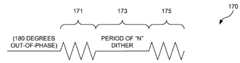
- the impulse trains 171 , 175 of the waveform 170 generated by the driver D 2 140are 180 degrees ( ⁇ ) out of phase with the impulse trains 161 and 165 of the waveform 160 , however, but the period of the “N” dither 163 , 173 is the same for both drivers at this time.
- FIG. 2Cillustrated is a second dither period, N plus delta 183 of a waveform 180 at a different time than the generation of the period “N” dither of waveforms 160 , 170 .
- the impulse trains 181 , 185have substantially similar properties as the waveforms 161 , 165 , 171 , and 175 .
- the impulse trains 181 , 185are generated by the driver D 1 130 .
- the impulse trains 191 , 195 of the waveform 190 generated by the driver D 2 140have substantially similar properties to impulse trains 181 and 185 , and are also 180 degrees out of phase with impulse trains 181 , 185 .
- the period of time 193 between impulse trains 191 , 195is substantially similar to the period of time 183 between impulse trains 181 , 185 .
- the impulse trains 191 , 195 and the impulse trains 181 , 185are substantially 180 degrees out of phase with one another.
- a pulse trainis generated in step 310 and applied to either the first set of electrodes 142 or the second set of electrodes 144 , as appropriate.
- a dither of a selected amount of timesuch as a number of microseconds, is performed.
- the other set of electrodesis selected by the waveform generator 120 .
- step 350it is then determined in step 350 whether the direction of the dither is in the positive or negative direction. If the direction of the dither is in the positive direction, then in step 360 , the period between impulses is incremented by a ditherer, such as a dither circuit. If the direction of the dither is in the negative direction, then in step 370 , the period between impulses is decremented by a ditherer, such as a dither circuit. In step 380 , it is determined whether the ditherer is at either of two predefined boundaries, either upper or lower, for the dither period.
- step 310re-executes. However, if the ditherer is at either of two predefined boundaries, then in step 390 , the ditherer changes the direction, that is, increases if previously decreasing or decreases if previously increasing the dithering.
- the waveform generator 400has a battery save circuit/power off timer 420 , a placebo on/off switch 430 , and a dither/period oscillator 440 .
- the battery save circuit/power off timer 420can be used to turn off the power to drivers 130 , 140 if the system 100 has been generating dithered impulse trains for a set period of time, such as an hour, thereby reducing heat generation. This can also act as a safety feature for the patient.
- the placebo on/off switch 430can be used as a control for determining whether the subject believes that use of the device, on or off, is affecting him/her. For instance, a subject could believe that the system 100 has an effect when “on”, but does not have an affect when “off”. Therefore, the placebo switch can be used in both the on and off position, and the patient could believe that differing impulse trains are being applied, or even a complete lack of impulse trains. Therefore, the patients' outward symptoms could be studied and compared to his or her subjective belief.
- the dither/period circuit 440is used by the drivers 130 , 140 to drive the first and second set of electrodes 142 , 144 .
- This circuitcan generate waveforms as illustrated in FIGS. 2A-2D .
Landscapes
- Health & Medical Sciences (AREA)
- Life Sciences & Earth Sciences (AREA)
- Heart & Thoracic Surgery (AREA)
- Engineering & Computer Science (AREA)
- Neurology (AREA)
- Psychiatry (AREA)
- Psychology (AREA)
- Social Psychology (AREA)
- Developmental Disabilities (AREA)
- Biophysics (AREA)
- Child & Adolescent Psychology (AREA)
- Hospice & Palliative Care (AREA)
- Biomedical Technology (AREA)
- Nuclear Medicine, Radiotherapy & Molecular Imaging (AREA)
- Radiology & Medical Imaging (AREA)
- Animal Behavior & Ethology (AREA)
- General Health & Medical Sciences (AREA)
- Public Health (AREA)
- Veterinary Medicine (AREA)
- Electrotherapy Devices (AREA)
Abstract
Description
Claims (29)
Priority Applications (1)
| Application Number | Priority Date | Filing Date | Title |
|---|---|---|---|
| US10/912,630US7486993B2 (en) | 2004-08-05 | 2004-08-05 | Brain stimulation method and device |
Applications Claiming Priority (1)
| Application Number | Priority Date | Filing Date | Title |
|---|---|---|---|
| US10/912,630US7486993B2 (en) | 2004-08-05 | 2004-08-05 | Brain stimulation method and device |
Publications (2)
| Publication Number | Publication Date |
|---|---|
| US20060030897A1 US20060030897A1 (en) | 2006-02-09 |
| US7486993B2true US7486993B2 (en) | 2009-02-03 |
Family
ID=35758414
Family Applications (1)
| Application Number | Title | Priority Date | Filing Date |
|---|---|---|---|
| US10/912,630Expired - LifetimeUS7486993B2 (en) | 2004-08-05 | 2004-08-05 | Brain stimulation method and device |
Country Status (1)
| Country | Link |
|---|---|
| US (1) | US7486993B2 (en) |
Cited By (7)
| Publication number | Priority date | Publication date | Assignee | Title |
|---|---|---|---|---|
| US20080221644A1 (en)* | 2007-03-09 | 2008-09-11 | Enteromedics, Inc. | Remote monitoring and control of implantable devices |
| US20080300656A1 (en)* | 2007-05-31 | 2008-12-04 | Adrianus Donders | Implantable therapy system |
| US20090054955A1 (en)* | 2007-08-20 | 2009-02-26 | Kopell Brian H | Systems and Methods for Treating Neurological Disorders by Light Stimulation |
| US20100168815A1 (en)* | 2003-02-03 | 2010-07-01 | Enteromedics Inc. | Nerve stimulation and blocking for treatment of gastrointestinal disorders |
| US20100222843A1 (en)* | 2007-05-16 | 2010-09-02 | Peter Tass | Stimulation device |
| CN108572557A (en)* | 2018-04-13 | 2018-09-25 | 深圳迈睿智能科技有限公司 | The control system and control method of sleep environment |
| US12053288B2 (en) | 2022-04-22 | 2024-08-06 | NeuroGeneces Inc. | Sensing system with features for determining and predicting brain age and other electrophysiological metrics of a subject |
Families Citing this family (20)
| Publication number | Priority date | Publication date | Assignee | Title |
|---|---|---|---|---|
| US20060217782A1 (en)* | 1998-10-26 | 2006-09-28 | Boveja Birinder R | Method and system for cortical stimulation to provide adjunct (ADD-ON) therapy for stroke, tinnitus and other medical disorders using implantable and external components |
| US7062330B1 (en)* | 1998-10-26 | 2006-06-13 | Boveja Birinder R | Electrical stimulation adjunct (Add-ON) therapy for urinary incontinence and urological disorders using implanted lead stimulus-receiver and an external pulse generator |
| TWI226232B (en)* | 2003-11-27 | 2005-01-11 | Xie Neng Biotech Corp | Method for generating non-constant oscillatory configuration |
| US8121692B2 (en) | 2006-08-30 | 2012-02-21 | Cardiac Pacemakers, Inc. | Method and apparatus for neural stimulation with respiratory feedback |
| US8050765B2 (en) | 2006-08-30 | 2011-11-01 | Cardiac Pacemakers, Inc. | Method and apparatus for controlling neural stimulation during disordered breathing |
| DE102006042156B4 (en)* | 2006-09-06 | 2013-01-17 | Martin Tegenthoff | Device for influencing brain functions of a human |
| CA2732309C (en) | 2008-07-30 | 2018-04-10 | Ecole Polytechnique Federale De Lausanne (Epfl) | Apparatus and method for optimized stimulation of a neurological target |
| WO2010031180A1 (en)* | 2008-09-19 | 2010-03-25 | Terry William Burton Moore | A method and device for reducing muscle tension through electrical manipulation |
| US8612008B2 (en)* | 2008-10-23 | 2013-12-17 | Electromedical Products International, Inc. | Microcurrent and cranial electrotherapy stimulator for control of anxiety, insomnia, depression and pain |
| JP5667987B2 (en) | 2008-11-12 | 2015-02-12 | エコーレ ポリテクニーク フェデラーレ デ ローザンヌ (イーピーエフエル) | Micromachined nerve stimulation device |
| CA2782710C (en) | 2009-12-01 | 2019-01-22 | Ecole Polytechnique Federale De Lausanne | Microfabricated neurostimulation device and methods of making and using the same |
| CA2795159C (en) | 2010-04-01 | 2020-11-03 | Ecole Polytechnique Federale De Lausanne | Device for interacting with neurological tissue and methods of making and using the same |
| US11311718B2 (en) | 2014-05-16 | 2022-04-26 | Aleva Neurotherapeutics Sa | Device for interacting with neurological tissue and methods of making and using the same |
| WO2015173787A1 (en) | 2014-05-16 | 2015-11-19 | Aleva Neurotherapeutics Sa | Device for interacting with neurological tissue and methods of making and using the same |
| US9474894B2 (en) | 2014-08-27 | 2016-10-25 | Aleva Neurotherapeutics | Deep brain stimulation lead |
| US9403011B2 (en) | 2014-08-27 | 2016-08-02 | Aleva Neurotherapeutics | Leadless neurostimulator |
| US9925376B2 (en) | 2014-08-27 | 2018-03-27 | Aleva Neurotherapeutics | Treatment of autoimmune diseases with deep brain stimulation |
| US10076802B2 (en)* | 2014-12-19 | 2018-09-18 | Illinois Tool Works Inc. | Electric arc start systems and methods |
| US10702692B2 (en) | 2018-03-02 | 2020-07-07 | Aleva Neurotherapeutics | Neurostimulation device |
| GB202209708D0 (en)* | 2022-07-01 | 2022-08-17 | Univ Oxford Innovation Ltd | Selective entrainment of neural rhythms by neural stimulation |
Citations (18)
| Publication number | Priority date | Publication date | Assignee | Title |
|---|---|---|---|---|
| US768721A (en) | 1904-04-04 | 1904-08-30 | William Benedict Bassell | Electrode for therapeutical purposes. |
| US3388699A (en) | 1966-02-02 | 1968-06-18 | Professional Bionics Inc | Method and apparatus for inducing lethargic relaxation or sleep |
| US3620219A (en) | 1969-05-07 | 1971-11-16 | Donald E Barker | Facial nerve stimulator |
| US3659614A (en) | 1969-12-29 | 1972-05-02 | Bernard Jankelson | Adjustable headband carrying electrodes for electrically stimulating the facial and mandibular nerves |
| US3718132A (en)* | 1970-03-26 | 1973-02-27 | Neuro Syst Inc | Electrotherapy machine |
| US4226246A (en) | 1977-05-27 | 1980-10-07 | Carba Societe Anonyme | Apparatus for maintaining the negative potential of human, animal, and plant cells |
| US4907601A (en)* | 1988-06-15 | 1990-03-13 | Etama Ag | Electrotherapy arrangement |
| US4979508A (en) | 1984-10-09 | 1990-12-25 | Beck Stephen C | Apparatus for generating phosphenes |
| US5038780A (en)* | 1988-04-29 | 1991-08-13 | The Biotronics Research Corp. | Method and apparatus for capacitively regenerating tissue and bone |
| US6016449A (en) | 1997-10-27 | 2000-01-18 | Neuropace, Inc. | System for treatment of neurological disorders |
| US6041262A (en) | 1996-04-01 | 2000-03-21 | 314613 B.C. Ltd. | Hair regrowth method and apparatus |
| US20030018366A1 (en) | 2001-07-17 | 2003-01-23 | Lamont John | Method and apparatus to modify cranial electrical potentials to remediate psychiatric disorders and to enhance optimal brain functioning |
| US20030097161A1 (en) | 2000-07-13 | 2003-05-22 | Firlik Andrew D. | Methods and apparatus for effectuating a lasting change in a neural-function of a patient |
| US6591138B1 (en) | 2000-08-31 | 2003-07-08 | Neuropace, Inc. | Low frequency neurostimulator for the treatment of neurological disorders |
| US6641562B1 (en)* | 2000-05-10 | 2003-11-04 | Hps Medical, Inc. | Apparatus and method of intravenous fluid infusion |
| US6708064B2 (en)* | 2000-02-24 | 2004-03-16 | Ali R. Rezai | Modulation of the brain to affect psychiatric disorders |
| US20040088024A1 (en) | 2001-03-08 | 2004-05-06 | Firlik Andrew D. | Methods and apparatus for effectuating a lasting change in a neural-function of a patient |
| US7026927B2 (en)* | 2003-12-31 | 2006-04-11 | Calypso Medical Technologies, Inc. | Receiver used in marker localization sensing system and having dithering in excitation pulses |
- 2004
- 2004-08-05USUS10/912,630patent/US7486993B2/ennot_activeExpired - Lifetime
Patent Citations (18)
| Publication number | Priority date | Publication date | Assignee | Title |
|---|---|---|---|---|
| US768721A (en) | 1904-04-04 | 1904-08-30 | William Benedict Bassell | Electrode for therapeutical purposes. |
| US3388699A (en) | 1966-02-02 | 1968-06-18 | Professional Bionics Inc | Method and apparatus for inducing lethargic relaxation or sleep |
| US3620219A (en) | 1969-05-07 | 1971-11-16 | Donald E Barker | Facial nerve stimulator |
| US3659614A (en) | 1969-12-29 | 1972-05-02 | Bernard Jankelson | Adjustable headband carrying electrodes for electrically stimulating the facial and mandibular nerves |
| US3718132A (en)* | 1970-03-26 | 1973-02-27 | Neuro Syst Inc | Electrotherapy machine |
| US4226246A (en) | 1977-05-27 | 1980-10-07 | Carba Societe Anonyme | Apparatus for maintaining the negative potential of human, animal, and plant cells |
| US4979508A (en) | 1984-10-09 | 1990-12-25 | Beck Stephen C | Apparatus for generating phosphenes |
| US5038780A (en)* | 1988-04-29 | 1991-08-13 | The Biotronics Research Corp. | Method and apparatus for capacitively regenerating tissue and bone |
| US4907601A (en)* | 1988-06-15 | 1990-03-13 | Etama Ag | Electrotherapy arrangement |
| US6041262A (en) | 1996-04-01 | 2000-03-21 | 314613 B.C. Ltd. | Hair regrowth method and apparatus |
| US6016449A (en) | 1997-10-27 | 2000-01-18 | Neuropace, Inc. | System for treatment of neurological disorders |
| US6708064B2 (en)* | 2000-02-24 | 2004-03-16 | Ali R. Rezai | Modulation of the brain to affect psychiatric disorders |
| US6641562B1 (en)* | 2000-05-10 | 2003-11-04 | Hps Medical, Inc. | Apparatus and method of intravenous fluid infusion |
| US20030097161A1 (en) | 2000-07-13 | 2003-05-22 | Firlik Andrew D. | Methods and apparatus for effectuating a lasting change in a neural-function of a patient |
| US6591138B1 (en) | 2000-08-31 | 2003-07-08 | Neuropace, Inc. | Low frequency neurostimulator for the treatment of neurological disorders |
| US20040088024A1 (en) | 2001-03-08 | 2004-05-06 | Firlik Andrew D. | Methods and apparatus for effectuating a lasting change in a neural-function of a patient |
| US20030018366A1 (en) | 2001-07-17 | 2003-01-23 | Lamont John | Method and apparatus to modify cranial electrical potentials to remediate psychiatric disorders and to enhance optimal brain functioning |
| US7026927B2 (en)* | 2003-12-31 | 2006-04-11 | Calypso Medical Technologies, Inc. | Receiver used in marker localization sensing system and having dithering in excitation pulses |
Non-Patent Citations (1)
| Title |
|---|
| Ferdjallah, Mohammed, Acquisition and Analysis of Electroencephalographic Activity (EEG) in the Presence of Noise With Application to Cranial Electrotherapy Stimulation (CES), Dec. 1994, The University of Texas at Austin. |
Cited By (17)
| Publication number | Priority date | Publication date | Assignee | Title |
|---|---|---|---|---|
| US20100168815A1 (en)* | 2003-02-03 | 2010-07-01 | Enteromedics Inc. | Nerve stimulation and blocking for treatment of gastrointestinal disorders |
| US9682233B2 (en) | 2003-02-03 | 2017-06-20 | Enteromedics Inc. | Nerve stimulation and blocking for treatment of gastrointestinal disorders |
| US9174040B2 (en) | 2003-02-03 | 2015-11-03 | Enteromedics Inc. | Nerve stimulation and blocking for treatment of gastrointestinal disorders |
| US8538542B2 (en) | 2003-02-03 | 2013-09-17 | Enteromedics Inc. | Nerve stimulation and blocking for treatment of gastrointestinal disorders |
| US8010204B2 (en) | 2003-02-03 | 2011-08-30 | Enteromedics Inc. | Nerve blocking for treatment of gastrointestinal disorders |
| US8068918B2 (en) | 2007-03-09 | 2011-11-29 | Enteromedics Inc. | Remote monitoring and control of implantable devices |
| US20080221644A1 (en)* | 2007-03-09 | 2008-09-11 | Enteromedics, Inc. | Remote monitoring and control of implantable devices |
| US8521299B2 (en) | 2007-03-09 | 2013-08-27 | Enteromedics Inc. | Remote monitoring and control of implantable devices |
| US20100222843A1 (en)* | 2007-05-16 | 2010-09-02 | Peter Tass | Stimulation device |
| US8140167B2 (en) | 2007-05-31 | 2012-03-20 | Enteromedics, Inc. | Implantable therapy system with external component having multiple operating modes |
| US8532787B2 (en)* | 2007-05-31 | 2013-09-10 | Enteromedics Inc. | Implantable therapy system having multiple operating modes |
| US20080300654A1 (en)* | 2007-05-31 | 2008-12-04 | Scott Anthony Lambert | Implantable therapy system |
| US20080300657A1 (en)* | 2007-05-31 | 2008-12-04 | Mark Raymond Stultz | Therapy system |
| US20080300656A1 (en)* | 2007-05-31 | 2008-12-04 | Adrianus Donders | Implantable therapy system |
| US20090054955A1 (en)* | 2007-08-20 | 2009-02-26 | Kopell Brian H | Systems and Methods for Treating Neurological Disorders by Light Stimulation |
| CN108572557A (en)* | 2018-04-13 | 2018-09-25 | 深圳迈睿智能科技有限公司 | The control system and control method of sleep environment |
| US12053288B2 (en) | 2022-04-22 | 2024-08-06 | NeuroGeneces Inc. | Sensing system with features for determining and predicting brain age and other electrophysiological metrics of a subject |
Also Published As
| Publication number | Publication date |
|---|---|
| US20060030897A1 (en) | 2006-02-09 |
Similar Documents
| Publication | Publication Date | Title |
|---|---|---|
| US7486993B2 (en) | Brain stimulation method and device | |
| AU2020234681B2 (en) | Wearable peripheral nerve stimulation for the treatment of diseases utilizing rhythmic biological processes | |
| US20210338968A1 (en) | Systems, methods and devices for paired plasticity | |
| CN108042915B (en) | Method and system for altering body mass composition using galvanic vestibular stimulation | |
| KR20180033090A (en) | Brain stimulating apparatus | |
| JPH03505051A (en) | Method and device for generating electrical pulses for biological stimulation | |
| JP2021514782A (en) | Systems, devices and methods for nerve stimulation | |
| US9610443B1 (en) | Methods to trigger high amplitude oscillations or resonance in the cardiovascular system of a patient using electrical stimulation | |
| Chen et al. | Electrical stimulation of the rostral ventrolateral medulla promotes wakefulness in rats | |
| KR20230018153A (en) | Brainwave-induced disease symptom mitigation scheme stimulation methods and devices | |
| RU2226381C1 (en) | Method for restoring working capacity of human organism and treating the cases of chronic fatigue syndrome | |
| WO2012031456A2 (en) | Method for the treatment of autism | |
| WO2015024945A1 (en) | Systems and methods for electrotherapy combined with feedback from sensors | |
| Dimitrov et al. | Signals and systems for electrosleep | |
| RU2297253C2 (en) | Trans-cranial electrical stimulator and device for fastening electrodes of electrical trans-cranial stimulator | |
| Kublanov et al. | Neuroelectrostimulation from Natural Electricity to Multifactorial Systems: A Review. | |
| RU2617197C1 (en) | Method for treating patients with increased activity of regulatory systems | |
| CN118698027A (en) | Pulse generating device and system for pain relief, wearable device | |
| O'Clock Jr | A Study of Vagus Nerve Stimulation Issues and Techniques for Hemodynamic Control | |
| Tsai et al. | Autonomie feedback with brain entrainment | |
| Bremner et al. | Cervical Non-invasive Vagus Nerve Stimulation in Post-Traumatic Stress Disorder: A Clinical Practice Guideline from the Vagus Nerve Society | |
| Priori et al. | 20. Non-Invasive Brain Stimulation (NIBS): evolving concepts for clinical applications | |
| HK1221679B (en) | Method and system for altering body mass composition using galvanic vestibular stimulation |
Legal Events
| Date | Code | Title | Description |
|---|---|---|---|
| AS | Assignment | Owner name:NEUROTONE SYSTEMS, INC., TEXAS Free format text:ASSIGNMENT OF ASSIGNORS INTEREST;ASSIGNORS:GILMER, JAMES RAY;BUIE, JOHN G.;BUIE, JOHN R.;AND OTHERS;REEL/FRAME:015263/0024;SIGNING DATES FROM 20040918 TO 20040930 | |
| STCF | Information on status: patent grant | Free format text:PATENTED CASE | |
| AS | Assignment | Owner name:CARR, GREGORY W., TEXAS Free format text:ASSIGNMENT OF ASSIGNORS INTEREST;ASSIGNOR:NEUROTONE SYSTEMS, INC.;REEL/FRAME:026942/0316 Effective date:20110811 | |
| REMI | Maintenance fee reminder mailed | ||
| FPAY | Fee payment | Year of fee payment:4 | |
| SULP | Surcharge for late payment | ||
| AS | Assignment | Owner name:WORCHEL, BARRY JASON, HAWAII Free format text:ASSIGNMENT OF ASSIGNORS INTEREST;ASSIGNOR:CARR, GREGORY W;REEL/FRAME:031878/0732 Effective date:20140102 | |
| REMI | Maintenance fee reminder mailed | ||
| FPAY | Fee payment | Year of fee payment:8 | |
| SULP | Surcharge for late payment | Year of fee payment:7 | |
| FEPP | Fee payment procedure | Free format text:MAINTENANCE FEE REMINDER MAILED (ORIGINAL EVENT CODE: REM.); ENTITY STATUS OF PATENT OWNER: SMALL ENTITY | |
| FEPP | Fee payment procedure | Free format text:11.5 YR SURCHARGE- LATE PMT W/IN 6 MO, SMALL ENTITY (ORIGINAL EVENT CODE: M2556); ENTITY STATUS OF PATENT OWNER: SMALL ENTITY | |
| MAFP | Maintenance fee payment | Free format text:PAYMENT OF MAINTENANCE FEE, 12TH YR, SMALL ENTITY (ORIGINAL EVENT CODE: M2553); ENTITY STATUS OF PATENT OWNER: SMALL ENTITY Year of fee payment:12 |