US7486302B2 - Fisheye lens graphical user interfaces - Google Patents
Fisheye lens graphical user interfacesDownload PDFInfo
- Publication number
- US7486302B2 US7486302B2US11/104,571US10457105AUS7486302B2US 7486302 B2US7486302 B2US 7486302B2US 10457105 AUS10457105 AUS 10457105AUS 7486302 B2US7486302 B2US 7486302B2
- Authority
- US
- United States
- Prior art keywords
- lens
- region
- original image
- presentation
- interest
- Prior art date
- Legal status (The legal status is an assumption and is not a legal conclusion. Google has not performed a legal analysis and makes no representation as to the accuracy of the status listed.)
- Active, expires
Links
Images


Classifications
- G—PHYSICS
- G06—COMPUTING OR CALCULATING; COUNTING
- G06F—ELECTRIC DIGITAL DATA PROCESSING
- G06F3/00—Input arrangements for transferring data to be processed into a form capable of being handled by the computer; Output arrangements for transferring data from processing unit to output unit, e.g. interface arrangements
- G06F3/01—Input arrangements or combined input and output arrangements for interaction between user and computer
- G06F3/048—Interaction techniques based on graphical user interfaces [GUI]
- G06F3/0481—Interaction techniques based on graphical user interfaces [GUI] based on specific properties of the displayed interaction object or a metaphor-based environment, e.g. interaction with desktop elements like windows or icons, or assisted by a cursor's changing behaviour or appearance
- G—PHYSICS
- G06—COMPUTING OR CALCULATING; COUNTING
- G06F—ELECTRIC DIGITAL DATA PROCESSING
- G06F2203/00—Indexing scheme relating to G06F3/00 - G06F3/048
- G06F2203/048—Indexing scheme relating to G06F3/048
- G06F2203/04805—Virtual magnifying lens, i.e. window or frame movable on top of displayed information to enlarge it for better reading or selection
Definitions
- This inventionrelates to the field of computer graphics processing, and more specifically, to a method and system for adjusting detail-in-context lenses in detail-in-context presentations with graphical user interfaces.
- Modem computer graphics systemsare used for numerous applications such as flight training, surveillance, and even playing computer games. In general, these applications are launched by the computer graphics system's operating system upon selection by a user from a menu or other graphical user interface (“GUI”).
- GUIgraphical user interface
- a GUIis used to convey information to and receive commands from users and generally includes a variety of GUI objects or controls, including icons, toolbars, drop-down menus, text, dialog boxes, buttons, and the like.
- a usertypically interacts with a GUI by using a pointing device (e.g., a mouse) to position a pointer or cursor over an object and “clicking” on the object.
- a pointing devicee.g., a mouse
- One problem with these computer graphics systemsis their inability to effectively display detailed information for selected graphic objects when those objects are in the context of a larger image.
- a usermay require access to detailed information with respect to an object in order to closely examine the object, to interact with the object, or to interface with an external application or network through the object.
- the detailed informationmay be a close-up view of the object or a region of a digital map image.
- an applicationmay provide a GUI for a user to access and view detailed information for a selected object in a larger image, in doing so, the relative location of the object in the larger image may be lost to the user.
- the usermay have gained access to the detailed information required to interact with the object, the user may lose sight of the context within which that object is positioned in the larger image. This is especially so when the user must interact with the GUI using a computer mouse or keyboard. The interaction may further distract the user from the context in which the detailed information is to be understood. This problem is an example of what is often referred to as the “screen real estate problem”.
- a method for interacting with a region-of-interest in an original image displayed on a display screencomprising: applying a lens to the original image to produce a presentation for display on the display screen, the lens having a focal region for the region-of-interest at least partially surrounded by a shoulder region; receiving one or more first signals to interact with the region-of-interest when a cursor is positioned over the focal region in the presentation; and, receiving one or more second signals to adjust the lens through a graphical user interface (“GUI”) displayed over the lens when the cursor is positioned over the shoulder region in the presentation.
- GUIgraphical user interface
- a method for interacting with a region-of-interest in an original image displayed on a display screencomprising: applying a lens to the original image to produce a presentation for display on the display screen, the lens having within a perimeter, a focal region for the region-of-interest at least partially surrounded by a shoulder region; receiving one or more first signals to interact with the region-of-interest when a cursor is positioned over one of the focal region and shoulder region in the presentation; and, receiving one or more second signals to adjust the lens through a graphical user interface (“GUI”) displayed over the lens when the cursor is positioned over the perimeter of the lens in the presentation.
- GUIgraphical user interface
- a method for generating a presentation of a region-of-interest in an original image for display on a display screencomprising: receiving one or more first signals to define a boundary for the region-of-interest in the original image; receiving one or more second signals to adjust the boundary thereby defining a lens for the region-of-interest, the lens having within a perimeter, a focal region for the region-of-interest at least partially surrounded by a shoulder region, the perimeter having an extent and the focal region having a magnification both defined by the boundary; and, applying the lens to the original image to produce the presentation.
- a method for generating a presentation of a region-of-interest in an original image for display on a display screencomprising: applying a lens to the original image to produce a presentation for display on the display screen, the lens having a focal region for the region-of-interest at least partially surrounded by a shoulder region, the focal and shoulder regions separated by a perimeter; and, receiving one or more signals to reposition the lens when a cursor is positioned in the focal region and pushed against the perimeter.
- an apparatussuch as a data processing system, a method for adapting this system, as well as articles of manufacture such as a computer readable medium having program instructions recorded thereon for practising the method of the invention.
- FIG. 1is a graphical representation of the geometry for constructing a three-dimensional perspective viewing frustum, relative to an x, y, z coordinate system, in accordance with known elastic presentation space graphics technology;
- FIG. 2is a graphical representation of the geometry of a presentation in accordance with known elastic presentation space graphics technology
- FIG. 3is a block diagram illustrating a data processing system adapted for implementing an embodiment of the invention
- FIG. 4is a partial screen capture illustrating a GUI having lens control elements for user interaction with detail-in-context presentations in accordance with an embodiment of the invention
- FIG. 5is a partial screen capture illustrating a GUI having lens control elements, including a scoop control slide bar icon, for user interaction with detail-in-context presentations in accordance with an embodiment of the invention
- FIG. 6is a partial screen capture illustrating a GUI having designated regions for lens control and data interaction in accordance with an embodiment of the invention
- FIG. 7is a partial screen capture illustrating the GUI of FIG. 6 in which shading is used to indicate the regions for lens control and data interaction;
- FIG. 8is a partial screen capture illustrating a GUI having arrow icons presented on the sides of a lens for positioning the lens in accordance with an embodiment of the invention
- FIG. 9is a screen capture illustrating a GUI in which a tab icon is presented on a side of a lens for positioning the lens in accordance with an embodiment of the invention.
- FIG. 10is a partial screen capture illustrating a GUI for specifying and adjusting a lens through its focal region in accordance with an embodiment of the invention
- FIG. 11is a partial screen capture illustrating a lens specified with the GUI of FIG. 10 in accordance with an embodiment of the invention.
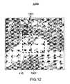
- FIG. 12is a partial screen capture illustrating a GUI having a button icon for switching between a current initial lens specification GUI and a subsequent lens adjustment GUI in accordance with an embodiment of the invention
- FIG. 13is a partial screen capture illustrating the subsequent lens adjustment GUI presented upon selection of the button icon of the GUI of FIG. 12 in accordance with an embodiment of the invention
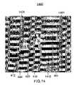
- FIG. 14is a partial screen capture illustrating a GUI for positioning a lens in accordance with an embodiment of the invention.
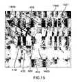
- FIG. 15is a partial screen capture illustrating the repositioning of a lens with the GUI of FIG. 14 in accordance with an embodiment of the invention.
- FIG. 16is a flow chart illustrating operations of software modules within the memory of the data processing system for interacting with a region-of-interest in an original image displayed on a display screen, in accordance with an embodiment of the invention.
- data processing systemis used herein to refer to any machine for processing data, including the computer systems and network arrangements described herein.
- the present inventionmay be implemented in any computer programming language provided that the operating system of the data processing system provides the facilities that may support the requirements of the present invention. Any limitations presented would be a result of a particular type of operating system or computer programming language and would not be a limitation of the present invention.
- the “screen real estate problem”generally arises whenever large amounts of information are to be displayed on a display screen of limited size.
- Known tools to address this probleminclude panning and zooming. While these tools are suitable for a large number of visual display applications, they become less effective where sections of the visual information are spatially related, such as in layered maps and three-dimensional representations, for example. In this type of information display, panning and zooming are not as effective as much of the context of the panned or zoomed display may be hidden.
- Detail-in-contextis the magnification of a particular region-of-interest (the “focal region” or “detail”) in a data presentation while preserving visibility of the surrounding information (the “context”).
- This techniquehas applicability to the display of large surface area media (e.g. digital maps) on computer screens of variable size including graphics workstations, laptop computers, personal digital assistants (“PDAs”), and cell phones.
- PDAspersonal digital assistants
- a representationis a formal system, or mapping, for specifying raw information or data that is stored in a computer or data processing system.
- a digital map of a cityis a representation of raw data including street names and the relative geographic location of streets and utilities. Such a representation may be displayed visually on a computer screen or printed on paper.
- a presentationis a spatial organization of a given representation that is appropriate for the task at hand.
- a presentation of a representationorganizes such things as the point of view and the relative emphasis of different parts or regions of the representation. For example, a digital map of a city may be presented with a region magnified to reveal street names.
- a detail-in-context presentationmay be considered as a distorted view (or distortion) of a portion of the original representation or image where the distortion is the result of the application of a “lens” like distortion function to the original representation.
- EPSElastic Presentation Space
- PDTPliable Display Technology
- detail-in-context data presentationsare characterized by magnification of areas of an image where detail is desired, in combination with compression of a restricted range of areas of the remaining information (i.e. the context), the result typically giving the appearance of a lens having been applied to the display surface.
- points in a representationare displaced in three dimensions and a perspective projection is used to display the points on a two-dimensional presentation display.
- the resulting presentationappears to be three-dimensional.
- the lens transformationappears to have stretched the continuous surface in a third dimension.
- EPS graphics technologya two-dimensional visual representation is placed onto a surface; this surface is placed in three-dimensional space; the surface, containing the representation, is viewed through perspective projection; and the surface is manipulated to effect the reorganization of image details.
- the presentation transformationis separated into two steps: surface manipulation or distortion and perspective projection.
- FIG. 1is a graphical representation of the geometry 100 for constructing a three-dimensional (“3D”) perspective viewing frustum 220 , relative to an x, y, z coordinate system, in accordance with known elastic presentation space (EPS) graphics technology.
- EPSelastic presentation space
- 2Dtwo-dimensional
- EPSmagnification of regions of interest and the accompanying compression of the contextual region to accommodate this change in scale are produced by the movement of regions of the surface towards the viewpoint (“VP”) 240 located at the apex of the pyramidal shape 220 containing the frustum.
- the process of projecting these transformed layouts via a perspective projectionresults in a new 2D layout which includes the zoomed and compressed regions.
- the use of the third dimension and perspective distortion to provide magnification in EPSprovides a meaningful metaphor for the process of distorting the information presentation surface.
- the 3D manipulation of the information presentation surface in such a systemis an intermediate step in the process of creating a new 2D layout of the information.
- FIG. 2is a graphical representation of the geometry 200 of a presentation in accordance with known EPS graphics technology.
- EPS graphics technologyemploys viewer-aligned perspective projections to produce detail-in-context presentations in a reference view plane 201 which may be viewed on a display.
- Undistorted 2D data pointsare located in a basal plane 210 of a 3D perspective viewing volume or frustum 220 which is defined by extreme rays 221 and 222 and the basal plane 210 .
- the VP 240is generally located above the centre point of the basal plane 210 and reference view plane (“RVP”) 201 . Points in the basal plane 210 are displaced upward onto a distorted surface 230 which is defined by a general 3D distortion function (i.e.
- the direction of the perspective projection corresponding to the distorted surface 230is indicated by the line FPo-FP 231 drawn from a point FPo 232 in the basal plane 210 through the point FP 233 which corresponds to the focus or focal region or focal point of the distorted surface 230 .
- the perspective projectionhas a direction 231 that is viewer-aligned (i.e., the points FPo 232 , FP 233 , and VP 240 are collinear).
- EPSis applicable to multidimensional data and is well suited to implementation on a computer for dynamic detail-in-context display on an electronic display surface such as a monitor.
- EPSis typically characterized by magnification of areas of an image where detail is desired 233 , in combination with compression of a restricted range of areas of the remaining information (i.e. the context) 234 , the end result typically giving the appearance of a lens 230 having been applied to the display surface.
- the areas of the lens 230 where compression occursmay be referred to as the “shoulder” 234 of the lens 230 .
- the area of the representation transformed by the lensmay be referred to as the “lensed area”.
- the lensed areathus includes the focal region and the shoulder.
- the source image or representation to be viewedis located in the basal plane 210 .
- Magnification 233 and compression 234are achieved through elevating elements of the source image relative to the basal plane 210 , and then projecting the resultant distorted surface onto the reference view plane 201 .
- EPSperforms detail-in-context presentation of n-dimensional data through the use of a procedure wherein the data is mapped into a region in an (n+1) dimensional space, manipulated through perspective projections in the (n+1) dimensional space, and then finally transformed back into n-dimensional space for presentation.
- EPShas numerous advantages over conventional zoom, pan, and scroll technologies, including the capability of preserving the visibility of information outside 234 the local region-of-interest 233 .
- EPScan be implemented through the projection of an image onto a reference plane 201 in the following manner.
- the source image or representationis located on a basal plane 210 , and those regions of interest 233 of the image for which magnification is desired are elevated so as to move them closer to a reference plane situated between the reference viewpoint 240 and the reference view plane 201 .
- Magnification of the focal region 233 closest to the RVP 201varies inversely with distance from the RVP 201 . As shown in FIGS.
- compression of regions 234 outside the focal region 233is a function of both distance from the RVP 201 , and the gradient of the function describing the vertical distance from the RVP 201 with respect to horizontal distance from the focal region 233 .
- the resultant combination of magnification 233 and compression 234 of the image as seen from the reference viewpoint 240results in a lens-like effect similar to that of a magnifying glass applied to the image.
- the various functions used to vary the magnification and compression of the source image via vertical displacement from the basal plane 210are described as lenses, lens types, or lens functions. Lens functions that describe basic lens types with point and circular focal regions, as well as certain more complex lenses and advanced capabilities such as folding, have previously been described by Carpendale.
- FIG. 3is a block diagram illustrating a data processing system 300 adapted to implement an embodiment of the invention.
- the data processing system 300is suitable for implementing EPS technology, for displaying detail-in-context presentations of representations in conjunction with a detail-in-context graphical user interface (GUI) 400 , as described below, and for adjusting detail-in-context lenses in detail-in-context presentations.
- the data processing system 300includes an input device 310 , a central processing unit (“CPU”) 320 , memory 330 , and a display 340 .
- the input device 310may include a keyboard, a mouse, a pen and tablet, a trackball, an eye tracking device, a position tracking device, or a similar device.
- the CPU 320may include dedicated coprocessors and memory devices.
- the memory 330may include RAM, ROM, databases, or disk devices.
- the display 340may include a computer screen, terminal device, or a hardcopy producing output device such as a printer or plotter.
- the data processing system 300has stored therein data representing sequences of instructions which when executed cause the method described herein to be performed.
- the data processing system 300may contain additional software and hardware a description of which is not necessary for understanding the invention.
- the data processing system 300includes computer executable programmed instructions for directing the system 300 to implement the embodiments of the present invention.
- the programmed instructionsmay be embodied in one or more software modules 331 resident in the memory 330 of the data processing system 300 .
- the programmed instructionsmay be embodied on a computer readable medium (such as a CD disk or floppy disk) which may be used for transporting the programmed instructions to the memory 330 of the data processing system 300 .
- the programmed instructionsmay be embedded in a computer-readable, signal-bearing medium that is uploaded to a network by a vendor or supplier of the programmed instructions, and this signal-bearing medium may be downloaded through an interface to the data processing system 300 from the network by end users or potential buyers.
- detail-in-context presentations of data using techniques such as pliable surfaces, as described by Carpendale,are useful in presenting large amounts of information on limited-size display surfaces.
- Detail-in-context viewsallow magnification of a particular region-of-interest (the “focal region”) 233 in a data presentation while preserving visibility of the surrounding information 210 .
- GUIsare described having lens control elements that can be implemented in software and applied to the editing of digital images and to the adjustment lenses in detail-in-context presentations.
- the softwarecan be loaded into and run by the data processing system 300 of FIG. 3 .
- FIG. 4is a partial screen capture illustrating a GUI 400 having lens control elements for user interaction with detail-in-context presentations in accordance with an embodiment of the invention.
- Detail-in-context presentationsare characterized by magnification of areas of an image where detail is desired, in combination with compression of a restricted range of areas of the remaining information (i.e. the context), the end result typically giving the appearance of a lens having been applied to the display screen surface.
- This lens 410includes a “focal region” 420 having high magnification, a surrounding “shoulder region” 430 where information is typically visibly compressed, and a “base” 412 surrounding the shoulder region 430 and defining the extent of the lens 410 .
- FIG. 4is a partial screen capture illustrating a GUI 400 having lens control elements for user interaction with detail-in-context presentations in accordance with an embodiment of the invention.
- Detail-in-context presentationsare characterized by magnification of areas of an image where detail is desired, in combination with compression of a restricted range of
- the lens 410is shown with a circular shaped base 412 (or outline) and with a focal region 420 lying near the center of the lens 410 .
- the lens 410 and focal region 420may have any desired shape.
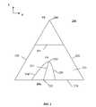
- the lens 410has a pyramid shape with a flat top 420 and trapezoidal shoulders 430 .
- the base of the lens 412may be coextensive with the focal region 420 .
- the GUI 400has lens control elements that, in combination, provide for the interactive control of the lens 410 .
- the effective control of the characteristics of the lens 410 by a useri.e., dynamic interaction with a detail-in-context lens
- one or more of these lens control elementsmay be made visible to the user on the display surface 340 by appearing as overlay icons on the lens 410 .
- Interaction with each elementis performed via the motion of an input or pointing device 310 (e.g., a mouse) with the motion resulting in an appropriate change in the corresponding lens characteristic.
- selection of which lens control element is actively controlled by the motion of the pointing device 310 at any given timeis determined by the proximity of the icon representing the pointing device 310 (e.g. cursor) on the display surface 340 to the appropriate component of the lens 410 .
- the icon representing the pointing device 310e.g. cursor
- “dragging” of the pointing device at the periphery of the bounding rectangle of the lens base 412causes a corresponding change in the size of the lens 410 (i.e. “resizing”).
- the GUI 400provides the user with a visual representation of which lens control element is being adjusted through the display of one or more corresponding icons.
- a two-dimensional pointing device 310that is a mouse, but it will be understood that the invention may be practiced with other 2D or 3D (or even greater numbers of dimensions) pointing devices including a trackball, a pen and tablet, a keyboard, an eye tracking device, and a position tracking device.
- a mouse 310controls the position of a cursor icon 401 that is displayed on the display screen 340 .
- the cursor 401is moved by moving the mouse 310 over a flat surface, such as the top of a desk, in the desired direction of movement of the cursor 401 .
- a flat surfacesuch as the top of a desk
- the two-dimensional movement of the mouse 310 on the flat surfacetranslates into a corresponding two-dimensional movement of the cursor 401 on the display screen 340 .
- a mouse 310typically has one or more finger actuated control buttons (i.e. mouse buttons). While the mouse buttons can be used for different functions such as selecting a menu option pointed at by the cursor 401 , the disclosed invention may use a single mouse button to “select” a lens 410 and to trace the movement of the cursor 401 along a desired path. Specifically, to select a lens 410 , the cursor 401 is first located within the extent of the lens 410 . In other words, the cursor 401 is “pointed” at the lens 410 . Next, the mouse button is depressed and released. That is, the mouse button is “clicked”. Selection is thus a point and click operation.
- the mouse buttonis depressed and released. That is, the mouse button is “clicked”. Selection is thus a point and click operation.
- the cursor 401is located at the desired starting location, the mouse button is depressed to signal the computer 320 to activate a lens control element, and the mouse 310 is moved while maintaining the button depressed. After the desired path has been traced, the mouse button is released.
- This procedureis often referred to as “clicking” and “dragging” (i.e. a click and drag operation). It will be understood that a predetermined key on a keyboard 310 could also be used to activate a mouse click or drag.
- clickingwill refer to the depression of a mouse button indicating a selection by the user and the term “dragging” will refer to the subsequent motion of the mouse 310 and cursor 401 without the release of the mouse button.
- the GUI 400may include the following lens control elements: move, pickup, resize base, resize focus, fold, magnify, zoom, and scoop. Each of these lens control elements has at least one lens control icon or alternate cursor icon associated with it.
- the following lens control iconsmay be displayed over the lens 410 : pickup icon 450 , base outline icon 412 , base bounding rectangle icon 411 , focal region bounding rectangle icon 421 , handle icons 481 , 482 , 491 , 492 (see FIG. 5 ) magnify slide bar icon 440 , zoom icon 495 , and scoop slide bar icon 540 (see FIG. 5 ).
- these iconsare displayed simultaneously after selection of the lens 410 .
- an alternate cursor icon 460 , 470 , 480 , 490 , 495may be displayed over the lens 410 to replace the cursor 401 or may be displayed in combination with the cursor 401 .
- bounding rectangle icons 411 , 421are displayed surrounding the base 412 and focal region 420 of the selected lens 410 to indicate that the lens 410 has been selected.
- bounding rectangles 411 , 421one might view them as glass windows enclosing the lens base 412 and focal region 420 , respectively.
- the bounding rectangles 411 , 421include handle icons 481 , 482 , 491 , 492 allowing for direct manipulation of the enclosed base 412 and focal region 420 as will be explained below.
- the bounding rectangles 411 , 421not only inform the user that the lens 410 has been selected, but also provide the user with indications as to what manipulation operations might be possible for the selected lens 410 though use of the displayed handles 481 , 482 , 491 , 492 .
- a bounding region having a shape other than generally rectangularSuch a bounding region could be of any of a great number of shapes including oblong, oval, ovoid, conical, cubic, cylindrical, polyhedral, spherical, etc.
- the cursor 401provides a visual cue indicating the nature of an available lens control element. As such, the cursor 401 will generally change in form by simply pointing to a different lens control icon 450 , 412 , 411 , 421 , 481 , 482 , 491 , 492 , 440 , 540 . For example, when resizing the base 412 of a lens 410 using a corner handle 491 , the cursor 401 will change form to a resize icon 490 once it is pointed at (i.e. positioned over) the corner handle 491 . The cursor 401 will remain in the form of the resize icon 490 until the cursor 401 has been moved away from the corner handle 491 .
- Lateral movement of a lens 410is provided by the move lens control element of the GUI 400 .
- This functionalityis accomplished by the user first selecting the lens 410 through a point and click operation. Then, the user points to a point within the lens 410 that is other than a point lying on a lens control icon 450 , 412 , 411 , 421 , 481 , 482 , 491 , 492 , 440 , 540 .
- a move icon 460is displayed over the lens 410 to replace the cursor 401 or may be displayed in combination with the cursor 401 .
- the move icon 460not only informs the user that the lens 410 may be moved, but also provides the user with indications as to what movement operations are possible for the selected lens 410 .
- the move icon 460may include arrowheads indicating up, down, left, and right motion.
- the lens 410is moved by a click and drag operation in which the user clicks and drags the lens 410 to the desired position on the screen 340 and then releases the mouse button 310 .
- the lens 410is locked in its new position until a further pickup and move operation is performed.
- Lateral movement of a lens 410is also provided by the pickup lens control element of the GUI. This functionality is accomplished by the user first selecting the lens 410 through a point and click operation. As mentioned above, when the lens 410 is selected a pickup icon 450 is displayed over the lens 410 near the centre of the lens 410 . Typically, the pickup icon 450 will be a crosshairs. In addition, a base outline 412 is displayed over the lens 410 representing the base 412 of the lens 410 . The crosshairs 450 and lens outline 412 not only inform the user that the lens has been selected, but also provides the user with an indication as to the pickup operation that is possible for the selected lens 410 . Next, the user points at the crosshairs 450 with the cursor 401 .
- the lens outline 412is moved by a click and drag operation in which the user clicks and drags the crosshairs 450 to the desired position on the screen 340 and then releases the mouse button 310 .
- the full lens 410is then moved to the new position and is locked there until a further pickup operation is performed.
- Resizing of the base 412 (or outline) of a lens 410is provided by the resize base lens control element of the GUI.
- a bounding rectangle icon 411is displayed surrounding the base 412 .
- the bounding rectangle icon 411may be coextensive with the perimeter of the base 412 .
- the bounding rectangle 411includes handles 491 . These handles 491 can be used to stretch the base 412 taller or shorter, wider or narrower, or proportionally larger or smaller.
- the corner handles 491will keep the proportions the same while changing the size.
- the middle handles 492(see FIG. 5 ) will make the base 412 taller or shorter, wider or narrower.
- Resizing the base 412 by the corner handles 491will keep the base 412 in proportion. Resizing the base 412 by the middle handles 492 will change the proportions of the base 412 . That is, the middle handles 492 change the aspect ratio of the base 412 (i.e. the ratio between the height and the width of the bounding rectangle 411 of the base 412 ).
- a resize icon 490may be displayed over the handle 491 to replace the cursor 401 or may be displayed in combination with the cursor 401 .
- the resize icon 490not only informs the user that the handle 491 may be selected, but also provides the user with indications as to the resizing operations that are possible with the selected handle.
- the resize icon 490 for a corner handle 491may include arrows indicating proportional resizing.
- the resize icon (not shown) for a middle handle 492may include arrows indicating width resizing or height resizing.
- Resizing of the focal region 420 of a lens 410is provided by the resize focus lens control element of the GUI.
- a bounding rectangle icon 421is displayed surrounding the focal region 420 .
- the bounding rectangle icon 421may be coextensive with the perimeter of the focal region 420 .
- the bounding rectangle 421includes handles 481 , 482 . These handles 481 , 482 can be used to stretch the focal region 420 taller or shorter, wider or narrower, or proportionally larger or smaller.
- the corner handles 481will keep the proportions the same while changing the size.
- the middle handles 482will make the focal region 420 taller or shorter, wider or narrower.
- Resizing the focal region 420 by the corner handles 481will keep the focal region 420 in proportion. Resizing the focal region 420 by the middle handles 482 will change the proportions of the focal region 420 . That is, the middle handles 482 change the aspect ratio of the focal region 420 (i.e. the ratio between the height and the width of the bounding rectangle 421 of the focal region 420 ).
- a resize icon 480may be displayed over the handle 481 , 482 to replace the cursor 401 or may be displayed in combination with the cursor 401 .
- the resize icon 480not only informs the user that a handle 481 , 482 may be selected, but also provides the user with indications as to the resizing operations that are possible with the selected handle.
- the resize icon 480 for a corner handle 481may include arrows indicating proportional resizing.
- the resize icon 480 for a middle handle 482may include arrows indicating width resizing or height resizing.
- Folding of the focal region 420 of a lens 410is provided by the fold control element of the GUI.
- control of the degree and direction of foldingi.e. skewing of the viewer aligned vector 231 as described by Carpendale
- the direction of foldingis determined by the direction in which the point 471 is dragged.
- the degree of foldingis determined by the magnitude of the translation of the cursor 401 during the drag.
- the direction and degree of foldingcorresponds to the relative displacement of the focus 420 with respect to the lens base 410 . In other words, and referring to FIG.
- the direction and degree of foldingcorresponds to the displacement of the point FP 233 relative to the point FPo 232 , where the vector joining the points FPo 232 and FP 233 defines the viewer aligned vector 231 .
- a bounding rectangle icon 421is displayed surrounding the focal region 420 .
- the bounding rectangle 421includes handles 481 , 482 .
- a fold icon 470may be displayed over the point 471 to replace the cursor 401 or may be displayed in combination with the cursor 401 .
- the fold icon 470not only informs the user that a point 471 on the bounding rectangle 421 may be selected, but also provides the user with indications as to what fold operations are possible.
- the fold icon 470may include arrowheads indicating up, down, left, and right motion.
- Magnification of the lens 410is provided by the magnify lens control element of the GUI.
- the magnify controlis presented to the user as a slide bar icon 440 near or adjacent to the lens 410 and typically to one side of the lens 410 .
- Sliding the bar 441 of the slide bar 440results in a proportional change in the magnification of the lens 410 .
- the slide bar 440not only informs the user that magnification of the lens 410 may be selected, but also provides the user with an indication as to what level of magnification is possible.
- the slide bar 440includes a bar 441 that may be slid up and down, or left and right, to adjust and indicate the level of magnification.
- the userwould click on the bar 441 of the slide bar 440 and drag in the direction of desired magnification level. Once the desired level of magnification is reached, the user would release the mouse button 310 .
- the lens 410is then locked with the selected magnification until a further magnification operation is performed.
- the focal region 420is an area of the lens 410 having constant magnification (i.e. if the focal region is a plane). Again referring to FIGS. 1 and 2 , magnification of the focal region 420 , 233 varies inversely with the distance from the focal region 420 , 233 to the reference view plane (RVP) 201 .
- RVPreference view plane
- Magnification of areas lying in the shoulder region 430 of the lens 410also varies inversely with their distance from the RVP 201 .
- magnification of areas lying in the shoulder region 430will range from unity at the base 412 to the level of magnification of the focal region 420 .
- Zoom functionalityis provided by the zoom lens control element of the GUI.
- the zoom lens control elementallows a user to quickly navigate to a region-of-interest 233 within a continuous view of a larger presentation 210 and then zoom in to that region-of-interest 233 for detailed viewing or editing.
- the combined presentation area covered by the focal region 420 and shoulder region 430 and surrounded by the base 412may be referred to as the “extent of the lens”.
- the presentation area covered by the focal region 420may be referred to as the “extent of the focal region”.
- the extent of the lensmay be indicated to a user by a base bounding rectangle 411 when the lens 410 is selected.
- the extent of the lensmay also be indicated by an arbitrarily shaped figure that bounds or is coincident with the perimeter of the base 412 .
- the extent of the focal regionmay be indicated by a second bounding rectangle 421 or arbitrarily shaped figure.
- the zoom lens control elementallows a user to: (a) “zoom in” to the extent of the focal region such that the extent of the focal region fills the display screen 340 (i.e. “zoom to focal region extent”); (b) “zoom in” to the extent of the lens such that the extent of the lens fills the display screen 340 (i.e. “zoom to lens extent”); or, (c) “zoom in” to the area lying outside of the extent of the focal region such that the area without the focal region is magnified to the same level as the extent of the focal region (i.e. “zoom to scale”).
- a bounding rectangle icon 411is displayed surrounding the base 412 and a bounding rectangle icon 421 is displayed surrounding the focal region 420 .
- Zoom functionalityis accomplished by the user first selecting the zoom icon 495 through a point and click operation
- a zoom cursor icon 496may be displayed to replace the cursor 401 or may be displayed in combination with the cursor 401 .
- the zoom cursor icon 496provides the user with indications as to what zoom operations are possible.
- the zoom cursor icon 496may include a magnifying glass.
- zoom to focal region extentsuch that the extent of the focal region fills the display screen 340
- zoom to lens extentTo zoom in to the extent of the lens such that the extent of the lens fills the display screen 340 (i.e. “zoom to lens extent”), the user would point and click within the extent of the lens.
- zoom in to the presentation area without the extent of the focal regionsuch that the area without the extent of the focal region is magnified to the same level as the extent of the focal region (i.e. “zoom to scale”), the user would point and click without the extent of the lens.
- the presentationis locked with the selected zoom until a further zoom operation is performed.
- a zoom function menu with multiple items (not shown) or multiple zoom function icons (not shown)may be used for zoom function selection.
- the zoom function menumay be presented as a pull-down menu.
- the zoom function iconsmay be presented in a toolbar or adjacent to the lens 410 when the lens is selected.
- Individual zoom function menu items or zoom function iconsmay be provided for each of the “zoom to focal region extent”, “zoom to lens extent”, and “zoom to scale” functions described above.
- a bounding rectangle icon 411may be displayed surrounding the base 412 and a bounding rectangle icon 421 may be displayed surrounding the focal region 420 .
- Zoom functionalityis accomplished by the user selecting a zoom function from the zoom function menu or via the zoom function icons using a point and click operation. In this way, a zoom function may be selected without considering the position of the cursor 401 within the lens 410 .
- the concavity or “scoop” of the shoulder region 430 of the lens 410is provided by the scoop lens control element of the GUI.
- the scoop controlis presented to the user as a slide bar icon 540 (see FIG. 5 ) near or adjacent to the lens 410 and typically below the lens 410 . Sliding the bar 541 (see FIG. 5 ) of the slide bar 540 results in a proportional change in the concavity or scoop of the shoulder region 430 of the lens 410 .
- the slide bar 540not only informs the user that the shape of the shoulder region 430 of the lens 410 may be selected, but also provides the user with an indication as to what degree of shaping is possible.
- the slide bar 540includes a bar 541 that may be slid left and right, or up and down, to adjust and indicate the degree of scooping.
- the userwould click on the bar 541 of the slide bar 540 and drag in the direction of desired scooping degree. Once the desired degree of scooping is reached, the user would release the mouse button 310 . The lens 410 is then locked with the selected scoop until a further scooping operation is performed.
- a usermay choose to hide one or more lens control icons 450 , 412 , 411 , 421 , 481 , 482 , 491 , 492 , 440 , 495 , 540 shown in FIGS. 4 and 5 from view so as not to impede the user's view of the image within the lens 410 .
- Thismay be helpful, for example, during an editing or move operation.
- a usermay select this option through means such as a menu, toolbar, or lens property dialog box.
- GUI 400maintains a record of control element operations such that the user may restore pre-operation presentations.
- This record of operationsmay be accessed by or presented to the user through “Undo” and “Redo” icons 497 , 498 , through a pull-down operation history menu (not shown), or through a toolbar.
- detail-in-context data viewing techniquesallow a user to view multiple levels of detail or resolution on one display 340 .
- the appearance of the data display or presentationis that of one or more virtual lenses showing detail 233 within the context of a larger area view 210 .
- Using multiple lenses in detail-in-context data presentationsmay be used to compare two regions of interest at the same time. Folding enhances this comparison by allowing the user to pull the regions of interest closer together.
- detail-in-context technologysuch as PDT
- an area of interestcan be magnified to pixel level resolution, or to any level of detail available from the source information, for in-depth review.
- the digital imagesmay include graphic images, maps, photographic images, or text documents, and the source information may be in raster, vector, or text form.
- a usercan define a lens 410 over the object using the GUI 400 .
- the lens 410may be introduced to the original image to form the a presentation through the use of a pull-down menu selection, tool bar icon, etc.
- lens control elements for the GUI 400such as move, pickup, resize base, resize focus, fold, magnify, zoom, and scoop, as described above, the user adjusts the lens 410 for detailed viewing of the object or area.
- the magnify lens control elementfor example, the user may magnify the focal region 420 of the lens 410 to pixel quality resolution revealing detailed information pertaining to the selected object or area.
- a base imagei.e., the image outside the extent of the lens
- a lens imagei.e., the image within the extent of the lens
- the data processing system 300employs EPS techniques with an input device 310 and GUI 400 for selecting objects or areas for detailed display to a user on a display screen 340 .
- Data representing an original image or representationis received by the CPU 320 of the data processing system 300 .
- the CPU 320processes the data in accordance with instructions received from the user via an input device 310 and GUI 400 to produce a detail-in-context presentation. The presentation is presented to the user on a display screen 340 . It will be understood that the CPU 320 may apply a transformation to the shoulder region 430 surrounding the region-of-interest 420 to affect blending or folding in accordance with EPS technology.
- the transformationmay map the region-of-interest 420 and/or shoulder region 430 to a predefined lens surface, defined by a transformation or distortion function and having a variety of shapes, using EPS techniques.
- the lens 410may be simply coextensive with the region-of-interest 420 .
- the lens control elements of the GUI 400are adjusted by the user via an input device 310 to control the characteristics of the lens 410 in the detail-in-context presentation.
- an input device 310such as a mouse
- a useradjusts parameters of the lens 410 using icons and scroll bars of the GUI 400 that are displayed over the lens 410 on the display screen 340 .
- the usermay also adjust parameters of the image of the full scene.
- Signals representing input device 310 movements and selectionsare transmitted to the CPU 320 of the data processing system 300 where they are translated into instructions for lens control.
- the lens 410may be added to the presentation before or after the object or area is selected. That is, the user may first add a lens 410 to a presentation or the user may move a pre-existing lens into place over the selected object or area.
- the lens 410may be introduced to the original image to form the presentation through the use of a pull-down menu selection, tool bar icon, etc.
- a usercan view a large area (i.e., outside the extent of the lens 410 ) while focusing in on a smaller area (or within the focal region 420 of the lens 410 ) surrounding the selected object. This makes it possible for a user to accurately gather detailed information without losing visibility or context of the portion of the original image surrounding the selected object.
- GUIsare provided for manipulating fisheye lenses and associated representation data.
- FIG. 5is a partial screen capture illustrating a GUI 500 having lens control elements, including a scoop control slide bar icon 540 , 541 , for user interaction with detail-in-context presentations in accordance with an embodiment of the invention. If a user clicks and drags on the lens focal region 420 while in “lens mode”, the lens 410 will be translated according to the mouse movements.
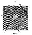
- FIG. 6is a partial screen capture illustrating a GUI 600 having designated regions for lens control 430 and data interaction 420 in accordance with an embodiment of the invention.
- the focal region 420 of the lens 410is reserved for direct interaction with the underlying data using a tool currently selected by the user.
- the toolmay be a drawing tool or an editing tool, etc.
- the shoulder region 430is reserved for lens control.
- the focal region 420 and shoulder region 430are separated by the focal region bounding rectangle icon 421 and its handle icons 481 , 482 for adjusting the focal region 420 .
- the currently selected tooloperates in the focal region 420 of the lens 410 , whereas clicking elsewhere 430 , 481 , 482 in the lens 410 manipulates the lens 410 itself.
- the GUI 600provides modeless switching between lens interaction and data interaction functions.
- a usercan seamlessly switch from a mode for adjusting lens parameters to a mode for interacting with representation data.
- no GUI lens control elementsare located in the focal region 420 (or alternatively in the lensed area 420 , 430 ) which frees up this region to be used for data manipulation.
- With dedicated regions for both data interaction and lens interactionit is no longer necessary to have a special mode for lens interaction. Lens interaction is always possible, regardless of what application tool (e.g., draw, edit, cut, paste, etc.) the user has selected.
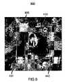
- FIG. 7is a partial screen capture illustrating the GUI 600 of FIG. 6 in which shading is used to indicate the regions for lens control 430 , 421 , 481 , 482 and data interaction 420 .
- the focal region 420is shaded in a first tone to identify it as a region for data interaction
- the focal region bounding rectangle and handle icons 421 , 481 , 492are shaded in a second tone to identify them as regions for lens control (i.e., focal region control)
- the shoulder region 430is shaded in a third tone to identify it as a region for lens control (i.e., lens movement).
- FIG. 8is a partial screen capture illustrating a GUI 800 having arrow icons 801 , 802 , 803 , 804 presented on the sides of a lens 410 for positioning the lens 410 in accordance with an embodiment of the invention.
- the entire region inside the bounds of the lens(the lensed region 420 , 430 ) is reserved for interaction with the data, as such, it is necessary to provide new lens control elements for adjusting the position of the lens 410 and for adjusting parameters for the focal region 420 .
- These control elementsare displayed outside the bounds 412 of the lens 410 so that the interior of the lens 420 , 430 can be used for data interaction.
- FIG. 8is a partial screen capture illustrating a GUI 800 having arrow icons 801 , 802 , 803 , 804 presented on the sides of a lens 410 for positioning the lens 410 in accordance with an embodiment of the invention.
- the entire region inside the bounds of the lens(the lensed region 420 , 430 ) is
- each side of the bounding rectangle icon 411 for the base 412 of the lens 410includes an arrow icon 801 , 802 , 803 , 804 for positioning the lens 410 .
- Each arrow icon 801 , 802 , 803 , 804is used to move the lens 410 in the one-dimensional direction in which the arrow is pointing (i.e., up 801 , left 802 , down 803 , right 804 ).
- each arrow icon 801 , 802 , 803 , 804can be used to move the lens 410 in two-dimensions.
- the lens 410is moved by a click and drag operation in which the user clicks and drags one of the arrow icons 801 , 802 , 803 , 804 to a desired position on the screen 340 and then releases the mouse button 310 .
- a slide bar 440is used to adjust the level of magnification for the lens 410 .
- Handles 491 on the bounding rectangle icon 411 for the base 412 of the lens 410are used to resize the bounds 412 of the lens 410 . No independent means are provided to resize the focal region 420 , rather, the handles 491 , 492 on the bounding rectangle icon 411 for the base 412 also function to resize the focal region 420 .
- resizing of the bounds 411 of the focal region 420is coupled to resizing of the bounds 412 of the base 412 of the lens 410 .
- the size (i.e., area) of lens base 412increases, the size of the focal region 420 increases correspondingly.
- the size of the focal region 420decreases correspondingly.
- a usermay chose the relationship between resizing of the base and focal region. For example, a menu item may be provided for selecting a constant ratio between the sizes of the base and the focal region (e.g., given a predetermined limit for the size of the base).
- a second menu itemmay be provided for selecting a constant absolute difference in size between the size of the base and the focal region (e.g., given a predetermined limit for the size of the base).
- FIG. 9is a screen capture illustrating a GUI 900 in which a tab icon 905 is presented on a side of a lens 410 for positioning the lens 410 in accordance with an embodiment of the invention.
- the entire region inside the bounds of the lens(the lensed region 420 , 430 ) is reserved for interaction with the data, as such, it is necessary to provide new lens control elements for adjusting the position of the lens 410 and for adjusting parameters for the focal region 420 .
- These control elementsare displayed outside the bounds 412 of the lens 410 so that the interior of the lens 420 , 430 can be used for data interaction.
- one side of the bounding rectangle icon 411 for the base 412 of the lens 410includes a tab icon 905 for positioning the lens 410 .
- the tab icon 905is used to move the lens 410 in two-dimensions.
- the lens 410is moved by a click and drag operation in which the user clicks and drags on the tab icon 905 to a desired position on the screen 340 and then releases the mouse button 310 .
- a slide bar 440is used to adjust the level of magnification for the lens 410 .
- Handles 491 , 492 on the bounding rectangle icon 411 for the base 412 of the lens 410are used to resize the bounds 412 of the lens 410 .
- the handles 491 on the bounding rectangle icon 411 for the base 412also function to resize the focal region 420 .
- resizing of the bounds 411 of the focal region 420is coupled to resizing of the bounds 412 of the base 412 of the lens 410 .
- the size (i.e., area) of lens base 412increases, the size of the focal region 420 increases correspondingly.
- the size of the focal region 420decreases correspondingly.
- a usermay chose the relationship between resizing of the base and focal region by selecting from a menu.
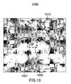
- FIG. 10is a partial screen capture illustrating a GUI 1000 for specifying and adjusting a lens through its focal region in accordance with an embodiment of the invention.
- FIG. 11is a partial screen capture illustrating a lens specified with the GUI 1000 of FIG. 10 in accordance with an embodiment of the invention.
- the GUI 1000 of FIG. 10includes a user defined bounding rectangle icon 1001 for a region-of-interest 1005 in the representation that will become the focal region 420 of the lens 410 presentation shown in FIG. 11 .
- the GUI 1000is used to specify a lens 410 as follows. First, an undistorted representation 1010 is displayed to a user on the display screen 340 . Second, the user identifies a region-of-interest 1005 in the representation 1010 that the user would like to have magnified.
- the useractivates a software module 331 (e.g., by selection a menu item in a pull down menu, etc.) allowing the user to draw a bounding rectangle icon 1001 around the region-of-interest 1005 by moving a cursor 401 on the display screen 340 with a pointing device 310 such as a mouse.
- the bounding rectangle icon 1001could have any other shape (e.g., a circle, polygon, etc.).
- the useradjusts the bounding rectangle icon 1001 to specify a magnification for the region-of-interest 1005 . The magnification so specified is used to generate a detail-in-context lens presentation 1110 (see FIG.
- the lens 410having a lens 410 with a focal region 420 sized in accordance with the specified magnification.
- the userspecifies the size (i.e., area) of the focal region 420 which defines a magnification for the region-of-interest 1005 .
- the focal region 420expands (or contracts)
- the lens bounds 412expands (or contracts) correspondingly.
- the GUI 1000 of FIGS. 10 and 11provides a simple means for a user to select a region-of-interest 1005 and then quickly magnify that region-of-interest to a desired level.
- the size of the focal region 420and hence the magnification of the lens, is adjusted directly by input from the user. That is, by pulling or pushing on a side of the bounding rectangle icon 1001 with a cursor 401 and mouse 310 , the size of the focal region 420 , magnification of the lens, and extent 412 of the lens 410 are specified.
- the GUI 1000can be used to further adjust the focal region 420 and hence the lens 410 .
- focal region sizeis related to magnification.
- changing the size of the focal region 420changes the amount of information from the original representation presented in the focal region 420 . That is, focal region size is not related to magnification (i.e., magnification remains constant when the size of the focal region is adjusted).
- FIG. 12is a partial screen capture illustrating a GUI 1200 having a button icon 1201 for switching between a current initial lens specification GUI 1000 and a subsequent lens adjustment GUI 500 in accordance with an embodiment of the invention.
- FIG. 13is a partial screen capture illustrating the subsequent lens adjustment GUI 500 presented upon selection of the button icon 1201 of the GUI 1200 of FIG. 12 in accordance with an embodiment of the invention.
- the method of specifying and adjusting a lens 410 using the GUI 1000 of FIGS. 10 and 11can be an initial step in a user interaction with the lens 410 . By this, it is meant that this initial step occurs only once. After this initial step, the lens control elements associated with the GUIs 400 , 500 of FIGS. 4 and 5 are used to adjust the lens 410 .
- the GUI 1200 of FIG. 12includes on the bounding rectangle icon 1001 of FIGS. 10 and 11 a button icon 1201 for selection by a user to indicate to software modules 331 in the data processing system 300 that initial specification of the lens 410 is complete.
- the button icon 1201is a “close box” icon 1201 .
- a menu item in a pull-down menu or an icon in a toolbarcould be provided as a means for indicating to the system 300 that the initial specification of the lens 410 has been completed.
- the GUI 1200 of FIG. 12transitions to the GUI 500 of FIG. 5 as shown in FIG. 13 .
- the GUI 1000 of FIGS. 10 and 11functions as both the initial means for specifying the lens 410 and the subsequent means for adjusting the lens 410 .
- the GUI 1000can include one or more of the lens control elements described with respect to the GUIs 400 , 500 , 600 , 700 , 800 , 900 of FIGS. 4-9 .
- FIG. 14is a partial screen capture illustrating a GUI 1400 for positioning a lens 410 in accordance with an embodiment of the invention.
- the lens 410has a circular shaped focal region 420 , shoulder region 430 , and base 412 .
- the lens 410may be of any other shape (e.g., rectangular, etc.).
- the position of the lens 410depends on the position of the cursor 401 within the presentation 1401 . If the cursor 401 is repositioned (i.e., by moving a mouse 310 ) within the perimeter 1405 of the focal region 420 of the lens 410 , the lens 410 remains in place.
- FIG. 15is a partial screen capture illustrating the repositioning of a lens with the GUI 1400 of FIG. 14 in accordance with an embodiment of the invention.
- the cursor 401is shown in contact with the inner side of the perimeter 1405 of the focal region 420 .
- the direction of movement of the lens 410 upon subsequent movement of the cursor 410is indicated by the multiple arrows 1510 .
- the lens 410may be repositioned within the presentation 1401 when the cursor 401 is “pushed” against the inner side of the perimeter 1405 of the focal region 420 .
- magnification for the lens 410can be adjusted using a scroll wheel provided on the mouse 310 , using commands entered through a keyboard, or by selection from a toolbar or menu. If the magnification level is reduced to zero, the lens 410 will not be included in the presentation 1401 and hence manipulation of the cursor 401 within the presentation 1401 will have no effect on lens positioning.
- the position of the cursor 410remains under the control of the pointing device. That is, the cursor 401 can't travel instantly from point to point, as it could were the pointing device a pen or stylus input device.
- the position of the lens 410 in the presentation 1401is governed by the movement of the cursor 410 by the mouse within the focal region 420 . As shown in FIGS.
- moving the cursor 401 about within the perimeter 1405 of the focal region 420does not move the lens, whereas moving the cursor 401 against the inner side of the perimeter 1405 of the focal region 420 causes the lens 410 to be repositioned such that the cursor 401 does not travel outside of the focal region 420 .
- the pointing device 310is a pen or stylus input device (such as those used with computer tablets)
- the device 310may be lifted from the tablet, moved to a different position, and then returned to the surface of the tablet.
- the cursor 401disappears from the display 340 when the pen 310 is lifted and reappears when the pen is returned to the surface of the tablet.
- the lens 410is repositioned correspondingly at the new position of the cursor 401 .
- the lens 410remains stationary until the cursor 401 is returned to within the perimeter 1405 of the focal region 420 .
- the lens 410is repositioned when the cursor 401 is pushed against the inner side of the perimeter 1405 of the focal region 420 .
- Magnification for the lens 410can be adjusted using commands entered through a keyboard, or by selection from a toolbar or menu.
- FIG. 16is a flow chart illustrating operations 1600 of software modules 331 within the memory 330 of the data processing system 300 for interacting with a region-of-interest in an original image displayed on a display screen 340 , in accordance with an embodiment of the invention.
- a lens 410is applied to the original image to produce a presentation for display on the display screen 340 , the lens 410 having a focal region 420 for the region-of-interest at least partially surrounded by a shoulder region 430 .
- one or more first signalsare received to interact with the region-of-interest when a cursor 401 is positioned over the focal region 420 in the presentation.
- one or more second signalsare received to adjust the lens 410 through a graphical user interface (“GUI”) 600 displayed over the lens 410 when the cursor 401 is positioned over the shoulder region 430 in the presentation.
- GUIgraphical user interface
- the step of applying 1602further includes displacing the original image onto the lens 230 , 410 and perspectively projecting the displacing onto a plane 201 in a direction 231 aligned with a viewpoint 240 for the region-of-interest 233 .
- the methodfurther includes displaying the presentation on the display screen 340 .
- the lens 410is a surface 230 .
- the GUI 600has means to adjust at least one of: a magnification for the focal region; a degree of scooping for the shoulder region; a size and a shape for the focal region; a size and a shape for a perimeter of the lens; and, a location for the lens within the original image.
- the methodfurther includes receiving the one or more first and second signals and signals to position the cursor 401 on the display screen 340 from a pointing device 310 manipulated by a user.
- the pointing device 310is at least one of a mouse, a pen and tablet, a trackball, a keyboard, an eye tracking device, and a position tracking device.
- the methodfurther includes applying first and second shades to the focal region 420 and shoulder region 430 , respectively, the first shade indicating that the focal region is for editing the original image and the second shade indicating that the shoulder region is for adjusting the lens 410 .
- sequences of instructions which when executed cause the method described herein to be performed by the data processing system 300 of FIG. 3can be contained in a data carrier product according to one embodiment of the invention.
- This data carrier productcan be loaded into and run by the data processing system 300 of FIG. 3 .
- the sequences of instructions which when executed cause the method described herein to be performed by the data processing system 300 of FIG. 3can be contained in a computer software product according to one embodiment of the invention.
- This computer software productcan be loaded into and run by the data processing system 300 of FIG. 3 .
- sequences of instructions which when executed cause the method described herein to be performed by the data processing system 300 of FIG. 3can be contained in an integrated circuit product including a coprocessor or memory according to one embodiment of the invention. This integrated circuit product can be installed in the data processing system 300 of FIG. 3 .
Landscapes
- Engineering & Computer Science (AREA)
- General Engineering & Computer Science (AREA)
- Theoretical Computer Science (AREA)
- Human Computer Interaction (AREA)
- Physics & Mathematics (AREA)
- General Physics & Mathematics (AREA)
- User Interface Of Digital Computer (AREA)
Abstract
Description
Claims (31)
Priority Applications (2)
| Application Number | Priority Date | Filing Date | Title |
|---|---|---|---|
| US11/104,571US7486302B2 (en) | 2004-04-14 | 2005-04-13 | Fisheye lens graphical user interfaces |
| US12/364,450US7773101B2 (en) | 2004-04-14 | 2009-02-02 | Fisheye lens graphical user interfaces |
Applications Claiming Priority (2)
| Application Number | Priority Date | Filing Date | Title |
|---|---|---|---|
| US56187604P | 2004-04-14 | 2004-04-14 | |
| US11/104,571US7486302B2 (en) | 2004-04-14 | 2005-04-13 | Fisheye lens graphical user interfaces |
Related Child Applications (1)
| Application Number | Title | Priority Date | Filing Date |
|---|---|---|---|
| US12/364,450ContinuationUS7773101B2 (en) | 2004-04-14 | 2009-02-02 | Fisheye lens graphical user interfaces |
Publications (2)
| Publication Number | Publication Date |
|---|---|
| US20050262447A1 US20050262447A1 (en) | 2005-11-24 |
| US7486302B2true US7486302B2 (en) | 2009-02-03 |
Family
ID=35376654
Family Applications (2)
| Application Number | Title | Priority Date | Filing Date |
|---|---|---|---|
| US11/104,571Active2026-05-24US7486302B2 (en) | 2004-04-14 | 2005-04-13 | Fisheye lens graphical user interfaces |
| US12/364,450Expired - Fee RelatedUS7773101B2 (en) | 2004-04-14 | 2009-02-02 | Fisheye lens graphical user interfaces |
Family Applications After (1)
| Application Number | Title | Priority Date | Filing Date |
|---|---|---|---|
| US12/364,450Expired - Fee RelatedUS7773101B2 (en) | 2004-04-14 | 2009-02-02 | Fisheye lens graphical user interfaces |
Country Status (1)
| Country | Link |
|---|---|
| US (2) | US7486302B2 (en) |
Cited By (40)
| Publication number | Priority date | Publication date | Assignee | Title |
|---|---|---|---|---|
| US20030151626A1 (en)* | 2002-02-05 | 2003-08-14 | Robert Komar | Fast rendering of pyramid lens distorted raster images |
| US20040125138A1 (en)* | 2002-10-10 | 2004-07-01 | Zeenat Jetha | Detail-in-context lenses for multi-layer images |
| US20050264894A1 (en)* | 2004-05-28 | 2005-12-01 | Idelix Software Inc. | Graphical user interfaces and occlusion prevention for fisheye lenses with line segment foci |
| US20050285861A1 (en)* | 2004-06-23 | 2005-12-29 | Idelix Software, Inc. | Detail-in-context lenses for navigation |
| US20060050091A1 (en)* | 2004-09-03 | 2006-03-09 | Idelix Software Inc. | Occlusion reduction and magnification for multidimensional data presentations |
| US20060192780A1 (en)* | 2001-11-07 | 2006-08-31 | Maria Lantin | Method and system for displaying stereoscopic detail-in-context presentations |
| US20060232585A1 (en)* | 2005-04-13 | 2006-10-19 | Idelix Software Inc. | Detail-in-context terrain displacement algorithm with optimizations |
| US20070083819A1 (en)* | 2005-10-12 | 2007-04-12 | Idelix Software Inc. | Method and system for generating pyramid fisheye lens detail-in-context presentations |
| US20070097109A1 (en)* | 2005-10-18 | 2007-05-03 | Idelix Software Inc. | Method and system for generating detail-in-context presentations in client/server systems |
| US20070130540A1 (en)* | 2001-05-03 | 2007-06-07 | Michael Doyle | Graphical user interface for detail-in-context presentations |
| US20070168873A1 (en)* | 2006-01-19 | 2007-07-19 | Lentz James L | Computer controlled user interactive display interface for accessing graphic tools with a minimum of display pointer movement |
| US20070198941A1 (en)* | 2001-06-12 | 2007-08-23 | David Baar | Graphical user interface with zoom for detail-in-context presentations |
| US20070236507A1 (en)* | 2006-04-11 | 2007-10-11 | Idelix Software Inc. | Method and system for transparency adjustment and occlusion resolution for urban landscape visualization |
| US20090141044A1 (en)* | 2004-04-14 | 2009-06-04 | Noregin Assets N.V., L.L.C. | Fisheye lens graphical user interfaces |
| US20090172587A1 (en)* | 2007-07-26 | 2009-07-02 | Idelix Software Inc. | Dynamic detail-in-context user interface for application access and content access on electronic displays |
| US20090284542A1 (en)* | 2001-06-12 | 2009-11-19 | Noregin Assets N.V., L.L.C. | Lens-defined adjustment of displays |
| US20100023894A1 (en)* | 2006-12-20 | 2010-01-28 | France Telecom | System for selecting elements displayed on a screen |
| US20100026718A1 (en)* | 2002-07-16 | 2010-02-04 | Noregin Assets N.V., L.L.C. | Detail-in-context lenses for digital image cropping, measurement and online maps |
| US20100045702A1 (en)* | 2003-11-17 | 2010-02-25 | Noregin Assets N.V., L.L.C. | Navigating Digital Images using Detail-in-context Lenses |
| US7761713B2 (en) | 2002-11-15 | 2010-07-20 | Baar David J P | Method and system for controlling access in detail-in-context presentations |
| US7978210B2 (en) | 2002-07-16 | 2011-07-12 | Noregin Assets N.V., L.L.C. | Detail-in-context lenses for digital image cropping and measurement |
| US20110175932A1 (en)* | 2010-01-21 | 2011-07-21 | Tobii Technology Ab | Eye tracker based contextual action |
| US7995078B2 (en) | 2004-09-29 | 2011-08-09 | Noregin Assets, N.V., L.L.C. | Compound lenses for multi-source data presentation |
| US8225225B2 (en) | 2002-07-17 | 2012-07-17 | Noregin Assets, N.V., L.L.C. | Graphical user interface having an attached toolbar for drag and drop editing in detail-in-context lens presentations |
| USRE43742E1 (en) | 2000-12-19 | 2012-10-16 | Noregin Assets N.V., L.L.C. | Method and system for enhanced detail-in-context viewing |
| US8311915B2 (en) | 2002-09-30 | 2012-11-13 | Noregin Assets, N.V., LLC | Detail-in-context lenses for interacting with objects in digital image presentations |
| US8316319B1 (en)* | 2011-05-16 | 2012-11-20 | Google Inc. | Efficient selection of characters and commands based on movement-inputs at a user-inerface |
| US8416266B2 (en) | 2001-05-03 | 2013-04-09 | Noregin Assetts N.V., L.L.C. | Interacting with detail-in-context presentations |
| US9265458B2 (en) | 2012-12-04 | 2016-02-23 | Sync-Think, Inc. | Application of smooth pursuit cognitive testing paradigms to clinical drug development |
| US9380976B2 (en) | 2013-03-11 | 2016-07-05 | Sync-Think, Inc. | Optical neuroinformatics |
| US9619020B2 (en) | 2013-03-01 | 2017-04-11 | Tobii Ab | Delay warp gaze interaction |
| US9864498B2 (en) | 2013-03-13 | 2018-01-09 | Tobii Ab | Automatic scrolling based on gaze detection |
| US9952883B2 (en) | 2014-08-05 | 2018-04-24 | Tobii Ab | Dynamic determination of hardware |
| US10146304B2 (en) | 2014-11-10 | 2018-12-04 | Irisvision, Inc. | Methods and apparatus for vision enhancement |
| US10317995B2 (en) | 2013-11-18 | 2019-06-11 | Tobii Ab | Component determination and gaze provoked interaction |
| US10558262B2 (en) | 2013-11-18 | 2020-02-11 | Tobii Ab | Component determination and gaze provoked interaction |
| US10963999B2 (en) | 2018-02-13 | 2021-03-30 | Irisvision, Inc. | Methods and apparatus for contrast sensitivity compensation |
| US11144119B2 (en) | 2015-05-01 | 2021-10-12 | Irisvision, Inc. | Methods and systems for generating a magnification region in output video images |
| US11372479B2 (en) | 2014-11-10 | 2022-06-28 | Irisvision, Inc. | Multi-modal vision enhancement system |
| US11546527B2 (en) | 2018-07-05 | 2023-01-03 | Irisvision, Inc. | Methods and apparatuses for compensating for retinitis pigmentosa |
Families Citing this family (27)
| Publication number | Priority date | Publication date | Assignee | Title |
|---|---|---|---|---|
| US20060082901A1 (en)* | 2004-10-14 | 2006-04-20 | Idelix Software Inc. | Interacting with detail-in-context presentations |
| US20110069086A1 (en)* | 2002-10-10 | 2011-03-24 | Shoemaker Garth B D | Detail-in-Context Presentations in Client/Server Systems |
| US7804508B2 (en)* | 2004-10-06 | 2010-09-28 | Apple Inc. | Viewing digital images on a display using a virtual loupe |
| US7705858B2 (en)* | 2004-10-06 | 2010-04-27 | Apple Inc. | Techniques for displaying digital images on a display |
| US7561157B2 (en)* | 2004-10-06 | 2009-07-14 | Apple Inc. | Compare mode for variable number of images |
| US8456488B2 (en)* | 2004-10-06 | 2013-06-04 | Apple Inc. | Displaying digital images using groups, stacks, and version sets |
| US20070100915A1 (en)* | 2005-10-31 | 2007-05-03 | Rose Daniel E | Methods for displaying dynamic suggestions in a user interface |
| US20070100883A1 (en)* | 2005-10-31 | 2007-05-03 | Rose Daniel E | Methods for providing audio feedback during the navigation of collections of information |
| US7693912B2 (en)* | 2005-10-31 | 2010-04-06 | Yahoo! Inc. | Methods for navigating collections of information in varying levels of detail |
| US7889212B2 (en)* | 2006-09-07 | 2011-02-15 | Apple Inc. | Magnifying visual information using a center-based loupe |
| US7936946B2 (en)* | 2007-02-23 | 2011-05-03 | Apple Inc. | Migration for old image database |
| US8775953B2 (en) | 2007-12-05 | 2014-07-08 | Apple Inc. | Collage display of image projects |
| US20090225073A1 (en)* | 2008-03-04 | 2009-09-10 | Seismic Micro-Technology, Inc. | Method for Editing Gridded Surfaces |
| US20090254867A1 (en)* | 2008-04-03 | 2009-10-08 | Microsoft Corporation | Zoom for annotatable margins |
| US20090307618A1 (en)* | 2008-06-05 | 2009-12-10 | Microsoft Corporation | Annotate at multiple levels |
| US8607148B2 (en)* | 2008-08-26 | 2013-12-10 | General Electric Company | Method and system for performing drag and drop operation |
| US9372590B2 (en) | 2008-09-26 | 2016-06-21 | Microsoft Technology Licensing, Llc | Magnifier panning interface for natural input devices |
| USD679709S1 (en)* | 2011-04-06 | 2013-04-09 | Inmusic Brands, Inc. | Book scanning device camera assembly and page compressor |
| JP5189709B2 (en) | 2010-07-07 | 2013-04-24 | パナソニック株式会社 | Terminal device and GUI screen generation method |
| CN103384872B (en)* | 2011-02-22 | 2016-10-12 | 惠普发展公司,有限责任合伙企业 | Method and computing system for facilitating user input |
| US20150135125A1 (en)* | 2013-11-12 | 2015-05-14 | Apple Inc. | Bubble loupes |
| KR20150083651A (en)* | 2014-01-10 | 2015-07-20 | 삼성전자주식회사 | Electronic apparatus and data displaying method thereof |
| US10585485B1 (en)* | 2014-11-10 | 2020-03-10 | Amazon Technologies, Inc. | Controlling content zoom level based on user head movement |
| KR102474244B1 (en) | 2015-11-20 | 2022-12-06 | 삼성전자주식회사 | Image display apparatus and operating method for the same |
| USD861030S1 (en)* | 2016-08-30 | 2019-09-24 | Canon Kabushiki Kaisha | Display screen with animated graphical user interface |
| US11315296B2 (en) | 2017-11-22 | 2022-04-26 | Google Llc | Dynamically varying visual properties of indicators on a digital map |
| US10942633B2 (en)* | 2018-12-20 | 2021-03-09 | Microsoft Technology Licensing, Llc | Interactive viewing and editing system |
Citations (6)
| Publication number | Priority date | Publication date | Assignee | Title |
|---|---|---|---|---|
| US5459488A (en)* | 1990-07-21 | 1995-10-17 | Robert Bosch Gmbh | Graphical user interface with fisheye adaptation principle |
| US5638523A (en)* | 1993-01-26 | 1997-06-10 | Sun Microsystems, Inc. | Method and apparatus for browsing information in a computer database |
| US5670984A (en)* | 1993-10-26 | 1997-09-23 | Xerox Corporation | Image lens |
| US6882755B2 (en)* | 2001-10-19 | 2005-04-19 | Hewlett-Packard Development Company, L.P. | Image transmission for low bandwidth with region of interest |
| US6924822B2 (en)* | 2000-12-21 | 2005-08-02 | Xerox Corporation | Magnification methods, systems, and computer program products for virtual three-dimensional books |
| US6975335B2 (en)* | 1999-12-28 | 2005-12-13 | International Business Machines Corporation | Method of displaying magnified and reduced areas and apparatus thereof |
Family Cites Families (236)
| Publication number | Priority date | Publication date | Assignee | Title |
|---|---|---|---|---|
| US3201546A (en) | 1961-07-24 | 1965-08-17 | Hart Mfg Canada Ltd | Power controlling device for electrical heating elements |
| DE3277247D1 (en) | 1982-12-22 | 1987-10-15 | Ibm | Image transformations on an interactive raster scan or matrix display |
| US4581647A (en)* | 1983-09-19 | 1986-04-08 | Vye Richard A | Computerized automatic focusing control system for multiple television cameras |
| US4630110A (en) | 1984-02-15 | 1986-12-16 | Supervision Control Systems, Inc. | Surveillance system |
| CA1274919A (en) | 1985-07-27 | 1990-10-02 | Akio Ohba | Method of forming curved surfaces and the apparatus |
| GB8611554D0 (en)* | 1986-05-12 | 1986-06-18 | Crosfield Electronics Ltd | Image display |
| US4888713B1 (en) | 1986-09-05 | 1993-10-12 | Cdi Technologies, Inc. | Surface detail mapping system |
| US4790028A (en) | 1986-09-12 | 1988-12-06 | Westinghouse Electric Corp. | Method and apparatus for generating variably scaled displays |
| US4985849A (en)* | 1987-06-12 | 1991-01-15 | Canon Kabushiki Kaisha | Image processing system for forming a slantwise-mapped or rotated modified image of an original image |
| US5185599A (en)* | 1987-10-26 | 1993-02-09 | Tektronix, Inc. | Local display bus architecture and communications method for Raster display |
| US5048077A (en) | 1988-07-25 | 1991-09-10 | Reflection Technology, Inc. | Telephone handset with full-page visual display |
| US4992866A (en)* | 1989-06-29 | 1991-02-12 | Morgan Jack B | Camera selection and positioning system and method |
| US5175808A (en) | 1989-09-12 | 1992-12-29 | Pixar | Method and apparatus for non-affine image warping |
| US5206721A (en)* | 1990-03-08 | 1993-04-27 | Fujitsu Limited | Television conference system |
| US5250934A (en) | 1990-12-31 | 1993-10-05 | Xerox Corporation | Method and apparatus for thinning printed images |
| US5258837A (en) | 1991-01-07 | 1993-11-02 | Zandar Research Limited | Multiple security video display |
| US5200818A (en)* | 1991-03-22 | 1993-04-06 | Inbal Neta | Video imaging system with interactive windowing capability |
| US5416900A (en)* | 1991-04-25 | 1995-05-16 | Lotus Development Corporation | Presentation manager |
| US5341466A (en) | 1991-05-09 | 1994-08-23 | New York University | Fractal computer user centerface with zooming capability |
| US5185667A (en)* | 1991-05-13 | 1993-02-09 | Telerobotics International, Inc. | Omniview motionless camera orientation system |
| US5375199A (en)* | 1991-06-04 | 1994-12-20 | Digital Equipment Corporation | System monitoring method and device including a graphical user interface to view and manipulate system information |
| US5227771A (en) | 1991-07-10 | 1993-07-13 | International Business Machines Corporation | Method and system for incrementally changing window size on a display |
| CA2077173C (en) | 1991-11-22 | 2003-04-22 | Michael Chen | Method and apparatus for direct manipulation of 3-d objects on computer displays |
| US5321807A (en) | 1991-11-27 | 1994-06-14 | Mumford Christopher J | Accelerated graphics display method |
| US5610653A (en)* | 1992-02-07 | 1997-03-11 | Abecassis; Max | Method and system for automatically tracking a zoomed video image |
| JPH05334427A (en) | 1992-06-03 | 1993-12-17 | Hitachi Ltd | Image scaling method |
| US5594859A (en)* | 1992-06-03 | 1997-01-14 | Digital Equipment Corporation | Graphical user interface for video teleconferencing |
| US5329310A (en) | 1992-06-30 | 1994-07-12 | The Walt Disney Company | Method and apparatus for controlling distortion of a projected image |
| US5432895A (en) | 1992-10-01 | 1995-07-11 | University Corporation For Atmospheric Research | Virtual reality imaging system |
| US5751289A (en)* | 1992-10-01 | 1998-05-12 | University Corporation For Atmospheric Research | Virtual reality imaging system with image replay |
| JP3256293B2 (en) | 1992-10-19 | 2002-02-12 | 富士写真光機株式会社 | Head control device for TV camera |
| US5623588A (en)* | 1992-12-14 | 1997-04-22 | New York University | Computer user interface with non-salience deemphasis |
| DE69315969T2 (en) | 1992-12-15 | 1998-07-30 | Sun Microsystems Inc | Presentation of information in a display system with transparent windows |
| US5818455A (en) | 1993-07-21 | 1998-10-06 | Xerox Corporation | Method and apparatus for operating on the model data structure of an image to produce human perceptible output using a viewing operation region having explicit multiple regions |
| CA2124505C (en) | 1993-07-21 | 2000-01-04 | William A. S. Buxton | User interface having simultaneously movable tools and cursor |
| US5581670A (en) | 1993-07-21 | 1996-12-03 | Xerox Corporation | User interface having movable sheet with click-through tools |
| US5596690A (en)* | 1993-07-21 | 1997-01-21 | Xerox Corporation | Method and apparatus for operating on an object-based model data structure to produce a second image in the spatial context of a first image |
| US5652851A (en) | 1993-07-21 | 1997-07-29 | Xerox Corporation | User interface technique for producing a second image in the spatial context of a first image using a model-based operation |
| JP2916076B2 (en)* | 1993-08-26 | 1999-07-05 | シャープ株式会社 | Image display device |
| EP0724809A1 (en) | 1993-10-20 | 1996-08-07 | Videoconferencing Systems, Inc. | Adaptive videoconferencing system |
| US5583977A (en) | 1993-10-21 | 1996-12-10 | Taligent, Inc. | Object-oriented curve manipulation system |
| JP3697276B2 (en) | 1993-10-27 | 2005-09-21 | ゼロックス コーポレイション | Image display method, image display apparatus, and image scaling method |
| US5473740A (en) | 1993-12-29 | 1995-12-05 | International Business Machines Corporation | Method and apparatus for interactively indicating image boundaries in digital image cropping |
| TW371334B (en)* | 1994-03-18 | 1999-10-01 | Hitachi Ltd | Method for retrieving database with image information |
| US5451998A (en) | 1994-04-04 | 1995-09-19 | Hamrick; Daniel C. | Home shopping video catalog |
| US5564004A (en) | 1994-04-13 | 1996-10-08 | International Business Machines Corporation | Method and system for facilitating the selection of icons |
| US5689628A (en) | 1994-04-14 | 1997-11-18 | Xerox Corporation | Coupling a display object to a viewpoint in a navigable workspace |
| AU2424295A (en) | 1994-04-21 | 1995-11-16 | Sandia Corporation | Multi-dimensional user oriented synthetic environment |
| USRE44685E1 (en)* | 1994-04-28 | 2013-12-31 | Opentv, Inc. | Apparatus for transmitting and receiving executable applications as for a multimedia system, and method and system to order an item using a distributed computing system |
| US5796426A (en) | 1994-05-27 | 1998-08-18 | Warp, Ltd. | Wide-angle image dewarping method and apparatus |
| US5521634A (en)* | 1994-06-17 | 1996-05-28 | Harris Corporation | Automatic detection and prioritized image transmission system and method |
| CA2195415A1 (en)* | 1994-07-26 | 1996-02-08 | Scott Anthony Rhodes | A video security system |
| JP2679637B2 (en) | 1994-08-30 | 1997-11-19 | 日本電気株式会社 | Image display device |
| US5613032A (en)* | 1994-09-02 | 1997-03-18 | Bell Communications Research, Inc. | System and method for recording, playing back and searching multimedia events wherein video, audio and text can be searched and retrieved |
| US6266085B1 (en) | 1994-11-17 | 2001-07-24 | Canon Kabushiki Kaisha | Camera imaging and magnification device |
| US5644758A (en) | 1994-12-13 | 1997-07-01 | Microsoft Corporation | Bitmap block transfer image conversion |
| US6204845B1 (en)* | 1994-12-16 | 2001-03-20 | International Business Machines Corporation | Ergonomic viewable object processor |
| JP3265893B2 (en)* | 1995-02-13 | 2002-03-18 | 株式会社日立製作所 | Image display device |
| JPH08223561A (en) | 1995-02-17 | 1996-08-30 | Nippon Denki Syst Kensetsu Kk | Method and device for controlling camera by the use of monitor area diagram |
| US5657246A (en) | 1995-03-07 | 1997-08-12 | Vtel Corporation | Method and apparatus for a video conference user interface |
| US5729673A (en)* | 1995-04-07 | 1998-03-17 | Avid Technology, Inc. | Direct manipulation of two-dimensional moving picture streams in three-dimensional space |
| JP3890621B2 (en)* | 1995-04-21 | 2007-03-07 | ソニー株式会社 | Image display apparatus and method |
| US5721853A (en)* | 1995-04-28 | 1998-02-24 | Ast Research, Inc. | Spot graphic display element with open locking and periodic animation |
| US5973694A (en) | 1995-06-02 | 1999-10-26 | Chatham Telecommunications, Inc., | Method of communication using sized icons, text, and audio |
| US5926209A (en) | 1995-07-14 | 1999-07-20 | Sensormatic Electronics Corporation | Video camera apparatus with compression system responsive to video camera adjustment |
| US6037939A (en)* | 1995-09-27 | 2000-03-14 | Sharp Kabushiki Kaisha | Method for enabling interactive manipulation of data retained in computer system, and a computer system for implementing the method |
| US6081277A (en) | 1995-09-28 | 2000-06-27 | Sony Corporation | Apparatus and method for controlling image display |
| JP3176541B2 (en) | 1995-10-16 | 2001-06-18 | シャープ株式会社 | Information retrieval device and information retrieval method |
| US5786814A (en) | 1995-11-03 | 1998-07-28 | Xerox Corporation | Computer controlled display system activities using correlated graphical and timeline interfaces for controlling replay of temporal data representing collaborative activities |
| JPH09123848A (en) | 1995-11-06 | 1997-05-13 | Toyota Motor Corp | Information display device for vehicles |
| US6266082B1 (en) | 1995-12-19 | 2001-07-24 | Canon Kabushiki Kaisha | Communication apparatus image processing apparatus communication method and image processing method |
| US5848231A (en) | 1996-02-12 | 1998-12-08 | Teitelbaum; Neil | System configuration contingent upon secure input |
| US6067372A (en)* | 1996-02-22 | 2000-05-23 | University Of Pittsburgh | Method and system to enhance robust identification of abnormal regions in radiographs |
| JPH09289606A (en)* | 1996-04-23 | 1997-11-04 | Canon Inc | Image display device and camera control device |
| JP3798469B2 (en) | 1996-04-26 | 2006-07-19 | パイオニア株式会社 | Navigation device |
| US5742272A (en)* | 1996-04-29 | 1998-04-21 | Ati Technologies Inc. | Accelerated full screen video playback |
| US5754348A (en)* | 1996-05-14 | 1998-05-19 | Planetweb, Inc. | Method for context-preserving magnification of digital image regions |
| US5731805A (en)* | 1996-06-25 | 1998-03-24 | Sun Microsystems, Inc. | Method and apparatus for eyetrack-driven text enlargement |
| EP0817123B1 (en)* | 1996-06-27 | 2001-09-12 | Kabushiki Kaisha Toshiba | Stereoscopic display system and method |
| TW348239B (en) | 1996-06-28 | 1998-12-21 | Cirrus Logic Inc | Embedding a transparency enable bit as part of a resizing bit block transfer operation |
| US6108005A (en) | 1996-08-30 | 2000-08-22 | Space Corporation | Method for producing a synthesized stereoscopic image |
| US6139434A (en) | 1996-09-24 | 2000-10-31 | Nintendo Co., Ltd. | Three-dimensional image processing apparatus with enhanced automatic and user point of view control |
| JPH10105362A (en) | 1996-09-30 | 1998-04-24 | Toshiba Corp | Portable information device and enlarged display control method |
| US5950216A (en) | 1996-11-12 | 1999-09-07 | International Business Machines Corporation | Method and system for marking and subsequently retrieving a collection of objects within a multipage compound document utilizing selectable page numbered dialog boxes |
| US6256115B1 (en) | 1997-02-21 | 2001-07-03 | Worldquest Network, Inc. | Facsimile network |
| US5991877A (en) | 1997-04-03 | 1999-11-23 | Lockheed Martin Corporation | Object-oriented trusted application framework |
| US6026376A (en)* | 1997-04-15 | 2000-02-15 | Kenney; John A. | Interactive electronic shopping system and method |
| US6073036A (en) | 1997-04-28 | 2000-06-06 | Nokia Mobile Phones Limited | Mobile station with touch input having automatic symbol magnification function |
| US6057844A (en) | 1997-04-28 | 2000-05-02 | Adobe Systems Incorporated | Drag operation gesture controller |
| US5949430A (en) | 1997-05-20 | 1999-09-07 | Microsoft Corporation | Peripheral lenses for simulating peripheral vision on a display device |
| US6204850B1 (en)* | 1997-05-30 | 2001-03-20 | Daniel R. Green | Scaleable camera model for the navigation and display of information structures using nested, bounded 3D coordinate spaces |
| JP3713696B2 (en) | 1997-06-02 | 2005-11-09 | ソニー株式会社 | Digital map enlargement / reduction display method, digital map enlargement / reduction display apparatus, and storage medium storing digital map enlargement / reduction display program |
| JP3667032B2 (en) | 1997-06-10 | 2005-07-06 | キヤノン株式会社 | Camera control system, control method thereof, and storage medium storing program for executing control |
| US6384849B1 (en)* | 1997-07-14 | 2002-05-07 | Microsoft Corporation | Method for displaying controls in a system using a graphical user interface |
| US6747610B1 (en) | 1997-07-22 | 2004-06-08 | Sanyo Electric Co., Ltd. | Stereoscopic image display apparatus capable of selectively displaying desired stereoscopic image |
| US6091771A (en) | 1997-08-01 | 2000-07-18 | Wells Fargo Alarm Services, Inc. | Workstation for video security system |
| US6256043B1 (en) | 1997-09-26 | 2001-07-03 | Lucent Technologies Inc. | Three dimensional virtual reality enhancement techniques |
| US7071971B2 (en) | 1997-08-25 | 2006-07-04 | Elbex Video Ltd. | Apparatus for identifying the scene location viewed via remotely operated television camera |
| US6271854B1 (en) | 1997-12-15 | 2001-08-07 | Intel Corporation | Method and apparatus for facilitating navigation in three-dimensional graphic scenes |
| US6075531A (en) | 1997-12-15 | 2000-06-13 | International Business Machines Corporation | Computer system and method of manipulating multiple graphical user interface components on a computer display with a proximity pointer |
| US6128024A (en) | 1997-12-18 | 2000-10-03 | Hewlett-Packard Company | Polar controller for defining and generating spiral-like shapes |
| US6133914A (en) | 1998-01-07 | 2000-10-17 | Rogers; David W. | Interactive graphical user interface |
| GB9800397D0 (en) | 1998-01-09 | 1998-03-04 | Philips Electronics Nv | Virtual environment viewpoint control |
| US7760187B2 (en)* | 2004-07-30 | 2010-07-20 | Apple Inc. | Visual expander |
| US8479122B2 (en)* | 2004-07-30 | 2013-07-02 | Apple Inc. | Gestures for touch sensitive input devices |
| US6201548B1 (en)* | 1998-02-24 | 2001-03-13 | Hewlett-Packard Company | Graphical user interface for image editing |
| US6346962B1 (en)* | 1998-02-27 | 2002-02-12 | International Business Machines Corporation | Control of video conferencing system with pointing device |
| US6192314B1 (en) | 1998-03-25 | 2001-02-20 | Navigation Technologies Corp. | Method and system for route calculation in a navigation application |
| US6084598A (en) | 1998-04-23 | 2000-07-04 | Chekerylla; James | Apparatus for modifying graphic images |
| US6278443B1 (en) | 1998-04-30 | 2001-08-21 | International Business Machines Corporation | Touch screen with random finger placement and rolling on screen to control the movement of information on-screen |
| US6154840A (en) | 1998-05-01 | 2000-11-28 | Northern Telecom Limited | System and method for transferring encrypted sections of documents across a computer network |
| US6320599B1 (en) | 1998-05-11 | 2001-11-20 | Sony Corporation | Zooming scale indicator in computer graphics |
| US6052110A (en)* | 1998-05-11 | 2000-04-18 | Sony Corporation | Dynamic control of zoom operation in computer graphics |
| US6064401A (en)* | 1998-05-28 | 2000-05-16 | Ncr Corporation | User interface controls for adjusting the display of multi-dimensional graphical plots |
| US6201546B1 (en)* | 1998-05-29 | 2001-03-13 | Point Cloud, Inc. | Systems and methods for generating three dimensional, textured models |
| EP0961232A3 (en)* | 1998-05-29 | 2001-06-27 | Canon Kabushiki Kaisha | Mosaic image generation |
| US6133915A (en) | 1998-06-17 | 2000-10-17 | Microsoft Corporation | System and method for customizing controls on a toolbar |
| US6504535B1 (en)* | 1998-06-30 | 2003-01-07 | Lucent Technologies Inc. | Display techniques for three-dimensional virtual reality |
| JP3420504B2 (en) | 1998-06-30 | 2003-06-23 | キヤノン株式会社 | Information processing method |
| US6064354A (en)* | 1998-07-01 | 2000-05-16 | Deluca; Michael Joseph | Stereoscopic user interface method and apparatus |
| US20010040585A1 (en) | 1998-08-18 | 2001-11-15 | Stephen A Hartford | Resizing multi-dimensionally rendered graphical images |
| US6160553A (en) | 1998-09-14 | 2000-12-12 | Microsoft Corporation | Methods, apparatus and data structures for providing a user interface, which exploits spatial memory in three-dimensions, to objects and in which object occlusion is avoided |
| JP3508915B2 (en) | 1998-09-18 | 2004-03-22 | シャープ株式会社 | Data display control method, data display control device, and computer-readable recording medium recording data display control program |
| US6612930B2 (en) | 1998-11-19 | 2003-09-02 | Nintendo Co., Ltd. | Video game apparatus and method with enhanced virtual camera control |
| US6631205B1 (en) | 1999-01-13 | 2003-10-07 | Canon Kabushiki Kaisha | Stereoscopic imaging in a portable document format |
| US6396962B1 (en)* | 1999-01-29 | 2002-05-28 | Sony Corporation | System and method for providing zooming video |
| US6304271B1 (en) | 1999-02-05 | 2001-10-16 | Sony Corporation | Apparatus and method for cropping an image in a zooming graphical user interface |
| JP2000242262A (en)* | 1999-02-18 | 2000-09-08 | Fujitsu Ltd | DISPLAY CONTROL DEVICE, DISPLAY CONTROL METHOD, AND RECORDING MEDIUM CONTAINING DISPLAY CONTROL PROGRAM |
| US6256737B1 (en) | 1999-03-09 | 2001-07-03 | Bionetrix Systems Corporation | System, method and computer program product for allowing access to enterprise resources using biometric devices |
| US6438576B1 (en) | 1999-03-29 | 2002-08-20 | International Business Machines Corporation | Method and apparatus of a collaborative proxy system for distributed deployment of object rendering |
| JP2000287047A (en)* | 1999-03-30 | 2000-10-13 | Nec Corp | Image reader |
| US6400848B1 (en) | 1999-03-30 | 2002-06-04 | Eastman Kodak Company | Method for modifying the perspective of a digital image |
| US6842175B1 (en)* | 1999-04-22 | 2005-01-11 | Fraunhofer Usa, Inc. | Tools for interacting with virtual environments |
| US6346938B1 (en)* | 1999-04-27 | 2002-02-12 | Harris Corporation | Computer-resident mechanism for manipulating, navigating through and mensurating displayed image of three-dimensional geometric model |
| US6407747B1 (en)* | 1999-05-07 | 2002-06-18 | Picsurf, Inc. | Computer screen image magnification system and method |
| US6359615B1 (en)* | 1999-05-11 | 2002-03-19 | Ericsson Inc. | Movable magnification icons for electronic device display screens |
| US6417867B1 (en) | 1999-05-27 | 2002-07-09 | Sharp Laboratories Of America, Inc. | Image downscaling using peripheral vision area localization |
| US6522341B1 (en)* | 1999-06-02 | 2003-02-18 | Matsushita Electric Industrial Co., Ltd. | Multi-layer image mixing apparatus |
| JP3619063B2 (en) | 1999-07-08 | 2005-02-09 | キヤノン株式会社 | Stereoscopic image processing apparatus, method thereof, stereoscopic parameter setting apparatus, method thereof and computer program storage medium |
| JP2001092989A (en) | 1999-07-21 | 2001-04-06 | Sega Corp | Image processing method and apparatus |
| US6584237B1 (en) | 1999-08-23 | 2003-06-24 | Pentax Corporation | Method and apparatus for expanding image data |
| JP3509652B2 (en) | 1999-08-23 | 2004-03-22 | 日本電気株式会社 | Projector device |
| US7246109B1 (en) | 1999-10-07 | 2007-07-17 | Koninklijke Philips Electronics N.V. | Method and apparatus for browsing using position information |
| US7197718B1 (en)* | 1999-10-18 | 2007-03-27 | Sharp Laboratories Of America, Inc. | Interactive virtual area browser for selecting and rescaling graphical representations of displayed data |
| US6515678B1 (en)* | 1999-11-18 | 2003-02-04 | Gateway, Inc. | Video magnifier for a display of data |
| US6731315B1 (en)* | 1999-11-30 | 2004-05-04 | International Business Machines Corporation | Method for selecting display parameters of a magnifiable cursor |
| US6577311B1 (en) | 1999-12-16 | 2003-06-10 | Picture Iq Corporation | Techniques for automatically providing a high-resolution rendering of a low resolution digital image in a distributed network |
| US20020033837A1 (en)* | 2000-01-10 | 2002-03-21 | Munro James A. | Multiple-image viewer |
| US6249281B1 (en) | 2000-02-28 | 2001-06-19 | Presenter.Com | On-demand presentation graphical user interface |
| US20020062245A1 (en)* | 2000-03-09 | 2002-05-23 | David Niu | System and method for generating real-time promotions on an electronic commerce world wide website to increase the likelihood of purchase |
| US7148898B1 (en)* | 2000-03-29 | 2006-12-12 | Sourceprose Corporation | System and method for synchronizing raster and vector map images |
| US7576730B2 (en)* | 2000-04-14 | 2009-08-18 | Picsel (Research) Limited | User interface systems and methods for viewing and manipulating digital documents |
| US7055095B1 (en)* | 2000-04-14 | 2006-05-30 | Picsel Research Limited | Systems and methods for digital document processing |
| US7009626B2 (en)* | 2000-04-14 | 2006-03-07 | Picsel Technologies Limited | Systems and methods for generating visual representations of graphical data and digital document processing |
| US20020101396A1 (en) | 2000-04-14 | 2002-08-01 | Huston James R. | Balanced binary color drive method for graphical displays and system implementing same |
| US6938218B1 (en) | 2000-04-28 | 2005-08-30 | James Nolen | Method and apparatus for three dimensional internet and computer file interface |
| US6608631B1 (en) | 2000-05-02 | 2003-08-19 | Pixar Amination Studios | Method, apparatus, and computer program product for geometric warps and deformations |
| CA2310945C (en) | 2000-06-05 | 2009-02-03 | Corel Corporation | System and method for magnifying and editing images |
| JP2001346031A (en) | 2000-06-05 | 2001-12-14 | Fuji Photo Film Co Ltd | Method and device for compositing image |
| US6307612B1 (en) | 2000-06-08 | 2001-10-23 | Three-Five Systems, Inc. | Liquid crystal display element having a precisely controlled cell gap and method of making same |
| KR20020000940A (en) | 2000-06-22 | 2002-01-09 | 구자홍 | Apparatus and method for correcting keystone |
| AU2001273111A1 (en)* | 2000-06-30 | 2002-01-14 | Anthony Romito | Method and apparatus for a GIS based search engine utilizing real time advertising |
| US6747611B1 (en) | 2000-07-27 | 2004-06-08 | International Business Machines Corporation | Compact optical system and packaging for head mounted display |
| CA2317336A1 (en) | 2000-09-06 | 2002-03-06 | David Cowperthwaite | Occlusion resolution operators for three-dimensional detail-in-context |
| US6911975B2 (en) | 2000-09-11 | 2005-06-28 | Canon Kabushiki Kaisha | Stereo image display apparatus and method, and storage medium |
| US6704034B1 (en)* | 2000-09-28 | 2004-03-09 | International Business Machines Corporation | Method and apparatus for providing accessibility through a context sensitive magnifying glass |
| US7233942B2 (en) | 2000-10-10 | 2007-06-19 | Truelocal Inc. | Method and apparatus for providing geographically authenticated electronic documents |
| CA2323569A1 (en)* | 2000-10-18 | 2002-04-18 | Advanced Numerical Methods Ltd. | Elastic presentation space |
| US7134092B2 (en) | 2000-11-13 | 2006-11-07 | James Nolen | Graphical user interface method and apparatus |
| US6590568B1 (en) | 2000-11-20 | 2003-07-08 | Nokia Corporation | Touch screen drag and drop input technique |
| US7443396B2 (en) | 2000-11-29 | 2008-10-28 | National Instruments Corporation | Instrument having a virtual magnifying glass for displaying magnified portions of a signal waveform |
| CA2341965A1 (en)* | 2000-12-19 | 2002-06-19 | Advanced Numerical Methods Ltd. | A method and system for inversion of detail-in-context presentations |
| CA2328795A1 (en) | 2000-12-19 | 2002-06-19 | Advanced Numerical Methods Ltd. | Applications and performance enhancements for detail-in-context viewing technology |
| US7941669B2 (en) | 2001-01-03 | 2011-05-10 | American Express Travel Related Services Company, Inc. | Method and apparatus for enabling a user to select an authentication method |
| US6731285B2 (en)* | 2001-01-11 | 2004-05-04 | International Business Machines Corporation | System and method for providing high performance image magnification in a web browser |
| US20020093567A1 (en) | 2001-01-12 | 2002-07-18 | International Business Machines Corporation | Method and system for generating a digital photographic proof |
| US6956590B1 (en) | 2001-02-28 | 2005-10-18 | Navteq North America, Llc | Method of providing visual continuity when panning and zooming with a map display |
| US7437670B2 (en) | 2001-03-29 | 2008-10-14 | International Business Machines Corporation | Magnifying the text of a link while still retaining browser function in the magnified display |
| US7102636B2 (en) | 2001-03-31 | 2006-09-05 | Intel Corporation | Spatial patches for graphics rendering |
| CA2350342A1 (en) | 2001-05-03 | 2002-11-03 | Idelix Software Inc. | Extension of detail-in-context data presentation with interface to full zoom function |
| CA2345803A1 (en)* | 2001-05-03 | 2002-11-03 | Idelix Software Inc. | User interface elements for pliable display technology implementations |
| US20060082901A1 (en)* | 2004-10-14 | 2006-04-20 | Idelix Software Inc. | Interacting with detail-in-context presentations |
| WO2002101534A1 (en)* | 2001-06-12 | 2002-12-19 | Idelix Software Inc. | Graphical user interface with zoom for detail-in-context presentations |
| US7084886B2 (en)* | 2002-07-16 | 2006-08-01 | Idelix Software Inc. | Using detail-in-context lenses for accurate digital image cropping and measurement |
| CA2394119A1 (en) | 2002-07-18 | 2004-01-18 | Idelix Software Inc. | Cropping and measuring with a single lens |
| CA2393708A1 (en) | 2002-07-16 | 2004-01-16 | Idelix Software Inc. | Applications of multiple lenses in detail-in-context data presentations |
| US9760235B2 (en) | 2001-06-12 | 2017-09-12 | Callahan Cellular L.L.C. | Lens-defined adjustment of displays |
| US20030006995A1 (en)* | 2001-06-15 | 2003-01-09 | Smith Randall B. | Orthogonal magnifier within a computer system display |
| US6741730B2 (en) | 2001-08-10 | 2004-05-25 | Visiongate, Inc. | Method and apparatus for three-dimensional imaging in the fourier domain |
| US6891618B2 (en)* | 2001-09-07 | 2005-05-10 | Wallac Oy | Optical instrument and process for measurement of samples |
| US6985865B1 (en)* | 2001-09-26 | 2006-01-10 | Sprint Spectrum L.P. | Method and system for enhanced response to voice commands in a voice command platform |
| CA2361341A1 (en) | 2001-11-07 | 2003-05-07 | Idelix Software Inc. | Use of detail-in-context presentation on stereoscopically paired images |
| US6885874B2 (en)* | 2001-11-27 | 2005-04-26 | Motorola, Inc. | Group location and route sharing system for communication units in a trunked communication system |
| US20030105795A1 (en) | 2001-11-30 | 2003-06-05 | Anderson Jeff M. | Image editing via batch commands |
| US6874126B1 (en)* | 2001-11-30 | 2005-03-29 | View Space Technologies | Method and apparatus for controlling content display by the cursor motion |
| US6833843B2 (en)* | 2001-12-03 | 2004-12-21 | Tempest Microsystems | Panoramic imaging and display system with canonical magnifier |
| US6690387B2 (en)* | 2001-12-28 | 2004-02-10 | Koninklijke Philips Electronics N.V. | Touch-screen image scrolling system and method |
| US7038680B2 (en)* | 2002-01-09 | 2006-05-02 | Xerox Corporation | System for graphical display and interactive exploratory analysis of data and data relationships |
| US20030137525A1 (en) | 2002-01-24 | 2003-07-24 | Smith Randall B. | Method and apparatus for facilitating motion-coupled magnification |
| AU2003217333A1 (en) | 2002-02-04 | 2003-09-02 | Polycom, Inc. | Apparatus and method for providing electronic image manipulation in video conferencing applications |
| CA2370751A1 (en) | 2002-02-05 | 2003-08-05 | Garth B.D. Shoemaker | Fast and accurate rendering of pliable display technology distortions using pre-calculated texel coverages |
| CA2370752A1 (en)* | 2002-02-05 | 2003-08-05 | Idelix Software Inc. | Fast rendering of pyramid lens distorted raster images |
| JP3870109B2 (en) | 2002-03-08 | 2007-01-17 | インターナショナル・ビジネス・マシーンズ・コーポレーション | Image display apparatus, image display method, and image display program |
| US7249327B2 (en) | 2002-03-22 | 2007-07-24 | Fuji Xerox Co., Ltd. | System and method for arranging, manipulating and displaying objects in a graphical user interface |
| US7614077B2 (en) | 2002-04-10 | 2009-11-03 | International Business Machines Corporation | Persistent access control of protected content |
| US20030210281A1 (en)* | 2002-05-07 | 2003-11-13 | Troy Ellis | Magnifying a thumbnail image of a document |
| CA2386560A1 (en) | 2002-05-15 | 2003-11-15 | Idelix Software Inc. | Controlling optical hardware and dynamic data viewing systems with detail-in-context viewing tools |
| CA2386702A1 (en) | 2002-05-17 | 2003-11-17 | Idelix Software Inc. | Computing the inverse of a pdt distortion |
| GB2396198B (en)* | 2002-05-22 | 2005-06-22 | Alex Colas | Linear proportional valve |
| US20070064018A1 (en)* | 2005-06-24 | 2007-03-22 | Idelix Software Inc. | Detail-in-context lenses for online maps |
| US8120624B2 (en)* | 2002-07-16 | 2012-02-21 | Noregin Assets N.V. L.L.C. | Detail-in-context lenses for digital image cropping, measurement and online maps |
| CA2393887A1 (en) | 2002-07-17 | 2004-01-17 | Idelix Software Inc. | Enhancements to user interface for detail-in-context data presentation |
| CA2406131A1 (en)* | 2002-09-30 | 2004-03-30 | Idelix Software Inc. | A graphical user interface using detail-in-context folding |
| CA2407383A1 (en) | 2002-10-10 | 2004-04-10 | Idelix Software Inc. | Editing multiple layers of a presentation using detail-in-context lenses |
| US20070097109A1 (en) | 2005-10-18 | 2007-05-03 | Idelix Software Inc. | Method and system for generating detail-in-context presentations in client/server systems |
| CA2449888A1 (en)* | 2003-11-17 | 2005-05-17 | Idelix Software Inc. | Navigating large images using detail-in-context fisheye rendering techniques |
| US7321824B1 (en)* | 2002-12-30 | 2008-01-22 | Aol Llc | Presenting a travel route using more than one presentation style |
| US6993538B2 (en)* | 2003-01-28 | 2006-01-31 | Microsoft Corporation | System and process for identifying objects and/or points nearby a given object or point |
| US7231609B2 (en) | 2003-02-03 | 2007-06-12 | Microsoft Corporation | System and method for accessing remote screen content |
| US7133054B2 (en) | 2004-03-17 | 2006-11-07 | Seadragon Software, Inc. | Methods and apparatus for navigating an image |
| CA2426512A1 (en) | 2003-04-22 | 2004-10-22 | Garth Shoemaker | Positioning and manipulating detail-in-context lenses in 2d and 3d data through the application of eye tracking or position tracking |
| US6906643B2 (en) | 2003-04-30 | 2005-06-14 | Hewlett-Packard Development Company, L.P. | Systems and methods of viewing, modifying, and interacting with “path-enhanced” multimedia |
| US7308158B2 (en) | 2003-06-20 | 2007-12-11 | Eastman Kodak Company | Imaging method and system |
| JP4035497B2 (en)* | 2003-09-26 | 2008-01-23 | キヤノン株式会社 | Image display system, image display apparatus, image display method, and program |
| US7312806B2 (en) | 2004-01-28 | 2007-12-25 | Idelix Software Inc. | Dynamic width adjustment for detail-in-context lenses |
| US7173636B2 (en)* | 2004-03-18 | 2007-02-06 | Idelix Software Inc. | Method and system for generating detail-in-context lens presentations for elevation data |
| US7865301B2 (en) | 2004-03-23 | 2011-01-04 | Google Inc. | Secondary map in digital mapping system |
| EP1741064A4 (en)* | 2004-03-23 | 2010-10-06 | Google Inc | A digital mapping system |
| US7486302B2 (en)* | 2004-04-14 | 2009-02-03 | Noregin Assets N.V., L.L.C. | Fisheye lens graphical user interfaces |
| CA2566280A1 (en) | 2004-05-19 | 2005-12-01 | Metacarta, Inc. | Systems and methods of geographical text indexing |
| US9317945B2 (en) | 2004-06-23 | 2016-04-19 | Callahan Cellular L.L.C. | Detail-in-context lenses for navigation |
| US7995078B2 (en)* | 2004-09-29 | 2011-08-09 | Noregin Assets, N.V., L.L.C. | Compound lenses for multi-source data presentation |
| US7580036B2 (en) | 2005-04-13 | 2009-08-25 | Catherine Montagnese | Detail-in-context terrain displacement algorithm with optimizations |
| US7900158B2 (en)* | 2005-08-04 | 2011-03-01 | Microsoft Corporation | Virtual magnifying glass with intuitive use enhancements |
| JP4735194B2 (en)* | 2005-10-31 | 2011-07-27 | ブラザー工業株式会社 | Inkjet recording device |
| US9026938B2 (en) | 2007-07-26 | 2015-05-05 | Noregin Assets N.V., L.L.C. | Dynamic detail-in-context user interface for application access and content access on electronic displays |
- 2005
- 2005-04-13USUS11/104,571patent/US7486302B2/enactiveActive
- 2009
- 2009-02-02USUS12/364,450patent/US7773101B2/ennot_activeExpired - Fee Related
Patent Citations (6)
| Publication number | Priority date | Publication date | Assignee | Title |
|---|---|---|---|---|
| US5459488A (en)* | 1990-07-21 | 1995-10-17 | Robert Bosch Gmbh | Graphical user interface with fisheye adaptation principle |
| US5638523A (en)* | 1993-01-26 | 1997-06-10 | Sun Microsystems, Inc. | Method and apparatus for browsing information in a computer database |
| US5670984A (en)* | 1993-10-26 | 1997-09-23 | Xerox Corporation | Image lens |
| US6975335B2 (en)* | 1999-12-28 | 2005-12-13 | International Business Machines Corporation | Method of displaying magnified and reduced areas and apparatus thereof |
| US6924822B2 (en)* | 2000-12-21 | 2005-08-02 | Xerox Corporation | Magnification methods, systems, and computer program products for virtual three-dimensional books |
| US6882755B2 (en)* | 2001-10-19 | 2005-04-19 | Hewlett-Packard Development Company, L.P. | Image transmission for low bandwidth with region of interest |
Non-Patent Citations (4)
| Title |
|---|
| Carpendale, M.S.T., "A Framework for Elastic Presentation Space" (Burnaby, British Columbia: Simon Fraser University, 1999). |
| Fitzmaurice, G. et al., "Tracking Menus", UIST 2003, pp. 71-79. |
| LaMar et al., A Magnification Lens for Interactive Volume Visualization, ACM, pp. 1-10.* |
| Stone et al., The movable filter as a user interface tool, pp. 306-312, Proceedings of CHI ACM, 1992.* |
Cited By (78)
| Publication number | Priority date | Publication date | Assignee | Title |
|---|---|---|---|---|
| USRE43742E1 (en) | 2000-12-19 | 2012-10-16 | Noregin Assets N.V., L.L.C. | Method and system for enhanced detail-in-context viewing |
| US20070130540A1 (en)* | 2001-05-03 | 2007-06-07 | Michael Doyle | Graphical user interface for detail-in-context presentations |
| US7966570B2 (en) | 2001-05-03 | 2011-06-21 | Noregin Assets N.V., L.L.C. | Graphical user interface for detail-in-context presentations |
| US8416266B2 (en) | 2001-05-03 | 2013-04-09 | Noregin Assetts N.V., L.L.C. | Interacting with detail-in-context presentations |
| US9760235B2 (en) | 2001-06-12 | 2017-09-12 | Callahan Cellular L.L.C. | Lens-defined adjustment of displays |
| US9323413B2 (en) | 2001-06-12 | 2016-04-26 | Callahan Cellular L.L.C. | Graphical user interface with zoom for detail-in-context presentations |
| US20090284542A1 (en)* | 2001-06-12 | 2009-11-19 | Noregin Assets N.V., L.L.C. | Lens-defined adjustment of displays |
| US20070198941A1 (en)* | 2001-06-12 | 2007-08-23 | David Baar | Graphical user interface with zoom for detail-in-context presentations |
| US20060192780A1 (en)* | 2001-11-07 | 2006-08-31 | Maria Lantin | Method and system for displaying stereoscopic detail-in-context presentations |
| US8947428B2 (en) | 2001-11-07 | 2015-02-03 | Noreign Assets N.V., L.L.C. | Method and system for displaying stereoscopic detail-in-context presentations |
| US8400450B2 (en) | 2001-11-07 | 2013-03-19 | Noregin Assets, N.V., L.L.C. | Method and system for displaying stereoscopic detail-in-context presentations |
| US7737976B2 (en) | 2001-11-07 | 2010-06-15 | Maria Lantin | Method and system for displaying stereoscopic detail-in-context presentations |
| US20100201785A1 (en)* | 2001-11-07 | 2010-08-12 | Maria Lantin | Method and system for displaying stereoscopic detail-in-context presentations |
| US20030151626A1 (en)* | 2002-02-05 | 2003-08-14 | Robert Komar | Fast rendering of pyramid lens distorted raster images |
| US7667699B2 (en) | 2002-02-05 | 2010-02-23 | Robert Komar | Fast rendering of pyramid lens distorted raster images |
| US8120624B2 (en) | 2002-07-16 | 2012-02-21 | Noregin Assets N.V. L.L.C. | Detail-in-context lenses for digital image cropping, measurement and online maps |
| US7978210B2 (en) | 2002-07-16 | 2011-07-12 | Noregin Assets N.V., L.L.C. | Detail-in-context lenses for digital image cropping and measurement |
| US20100026718A1 (en)* | 2002-07-16 | 2010-02-04 | Noregin Assets N.V., L.L.C. | Detail-in-context lenses for digital image cropping, measurement and online maps |
| US9804728B2 (en) | 2002-07-16 | 2017-10-31 | Callahan Cellular L.L.C. | Detail-in-context lenses for digital image cropping, measurement and online maps |
| US8225225B2 (en) | 2002-07-17 | 2012-07-17 | Noregin Assets, N.V., L.L.C. | Graphical user interface having an attached toolbar for drag and drop editing in detail-in-context lens presentations |
| US9400586B2 (en) | 2002-07-17 | 2016-07-26 | Callahan Cellular L.L.C. | Graphical user interface having an attached toolbar for drag and drop editing in detail-in-context lens presentations |
| US8311915B2 (en) | 2002-09-30 | 2012-11-13 | Noregin Assets, N.V., LLC | Detail-in-context lenses for interacting with objects in digital image presentations |
| US8577762B2 (en) | 2002-09-30 | 2013-11-05 | Noregin Assets N.V., L.L.C. | Detail-in-context lenses for interacting with objects in digital image presentations |
| US20040125138A1 (en)* | 2002-10-10 | 2004-07-01 | Zeenat Jetha | Detail-in-context lenses for multi-layer images |
| US7761713B2 (en) | 2002-11-15 | 2010-07-20 | Baar David J P | Method and system for controlling access in detail-in-context presentations |
| US8139089B2 (en)* | 2003-11-17 | 2012-03-20 | Noregin Assets, N.V., L.L.C. | Navigating digital images using detail-in-context lenses |
| US20100045702A1 (en)* | 2003-11-17 | 2010-02-25 | Noregin Assets N.V., L.L.C. | Navigating Digital Images using Detail-in-context Lenses |
| US9129367B2 (en) | 2003-11-17 | 2015-09-08 | Noregin Assets N.V., L.L.C. | Navigating digital images using detail-in-context lenses |
| US7773101B2 (en) | 2004-04-14 | 2010-08-10 | Shoemaker Garth B D | Fisheye lens graphical user interfaces |
| US20090141044A1 (en)* | 2004-04-14 | 2009-06-04 | Noregin Assets N.V., L.L.C. | Fisheye lens graphical user interfaces |
| US20050264894A1 (en)* | 2004-05-28 | 2005-12-01 | Idelix Software Inc. | Graphical user interfaces and occlusion prevention for fisheye lenses with line segment foci |
| US8350872B2 (en) | 2004-05-28 | 2013-01-08 | Noregin Assets N.V., L.L.C. | Graphical user interfaces and occlusion prevention for fisheye lenses with line segment foci |
| US8106927B2 (en) | 2004-05-28 | 2012-01-31 | Noregin Assets N.V., L.L.C. | Graphical user interfaces and occlusion prevention for fisheye lenses with line segment foci |
| US8711183B2 (en) | 2004-05-28 | 2014-04-29 | Noregin Assets N.V., L.L.C. | Graphical user interfaces and occlusion prevention for fisheye lenses with line segment foci |
| US9317945B2 (en) | 2004-06-23 | 2016-04-19 | Callahan Cellular L.L.C. | Detail-in-context lenses for navigation |
| US20050285861A1 (en)* | 2004-06-23 | 2005-12-29 | Idelix Software, Inc. | Detail-in-context lenses for navigation |
| US20060050091A1 (en)* | 2004-09-03 | 2006-03-09 | Idelix Software Inc. | Occlusion reduction and magnification for multidimensional data presentations |
| US8907948B2 (en) | 2004-09-03 | 2014-12-09 | Noregin Assets N.V., L.L.C. | Occlusion reduction and magnification for multidimensional data presentations |
| US7714859B2 (en) | 2004-09-03 | 2010-05-11 | Shoemaker Garth B D | Occlusion reduction and magnification for multidimensional data presentations |
| US9299186B2 (en) | 2004-09-03 | 2016-03-29 | Callahan Cellular L.L.C. | Occlusion reduction and magnification for multidimensional data presentations |
| US7995078B2 (en) | 2004-09-29 | 2011-08-09 | Noregin Assets, N.V., L.L.C. | Compound lenses for multi-source data presentation |
| US20060232585A1 (en)* | 2005-04-13 | 2006-10-19 | Idelix Software Inc. | Detail-in-context terrain displacement algorithm with optimizations |
| US7580036B2 (en) | 2005-04-13 | 2009-08-25 | Catherine Montagnese | Detail-in-context terrain displacement algorithm with optimizations |
| USRE44348E1 (en) | 2005-04-13 | 2013-07-09 | Noregin Assets N.V., L.L.C. | Detail-in-context terrain displacement algorithm with optimizations |
| US8687017B2 (en) | 2005-10-12 | 2014-04-01 | Noregin Assets N.V., L.L.C. | Method and system for generating pyramid fisheye lens detail-in-context presentations |
| US20070083819A1 (en)* | 2005-10-12 | 2007-04-12 | Idelix Software Inc. | Method and system for generating pyramid fisheye lens detail-in-context presentations |
| US8031206B2 (en) | 2005-10-12 | 2011-10-04 | Noregin Assets N.V., L.L.C. | Method and system for generating pyramid fisheye lens detail-in-context presentations |
| US20070097109A1 (en)* | 2005-10-18 | 2007-05-03 | Idelix Software Inc. | Method and system for generating detail-in-context presentations in client/server systems |
| US8250486B2 (en)* | 2006-01-19 | 2012-08-21 | International Business Machines Corporation | Computer controlled user interactive display interface for accessing graphic tools with a minimum of display pointer movement |
| US20070168873A1 (en)* | 2006-01-19 | 2007-07-19 | Lentz James L | Computer controlled user interactive display interface for accessing graphic tools with a minimum of display pointer movement |
| US20070236507A1 (en)* | 2006-04-11 | 2007-10-11 | Idelix Software Inc. | Method and system for transparency adjustment and occlusion resolution for urban landscape visualization |
| US8478026B2 (en) | 2006-04-11 | 2013-07-02 | Noregin Assets N.V., L.L.C. | Method and system for transparency adjustment and occlusion resolution for urban landscape visualization |
| US8675955B2 (en) | 2006-04-11 | 2014-03-18 | Noregin Assets N.V., L.L.C. | Method and system for transparency adjustment and occlusion resolution for urban landscape visualization |
| US7983473B2 (en) | 2006-04-11 | 2011-07-19 | Noregin Assets, N.V., L.L.C. | Transparency adjustment of a presentation |
| US8194972B2 (en) | 2006-04-11 | 2012-06-05 | Noregin Assets, N.V., L.L.C. | Method and system for transparency adjustment and occlusion resolution for urban landscape visualization |
| US20100023894A1 (en)* | 2006-12-20 | 2010-01-28 | France Telecom | System for selecting elements displayed on a screen |
| US9026938B2 (en) | 2007-07-26 | 2015-05-05 | Noregin Assets N.V., L.L.C. | Dynamic detail-in-context user interface for application access and content access on electronic displays |
| US20090172587A1 (en)* | 2007-07-26 | 2009-07-02 | Idelix Software Inc. | Dynamic detail-in-context user interface for application access and content access on electronic displays |
| US20110175932A1 (en)* | 2010-01-21 | 2011-07-21 | Tobii Technology Ab | Eye tracker based contextual action |
| US9507418B2 (en)* | 2010-01-21 | 2016-11-29 | Tobii Ab | Eye tracker based contextual action |
| US10353462B2 (en) | 2010-01-21 | 2019-07-16 | Tobii Ab | Eye tracker based contextual action |
| US8316319B1 (en)* | 2011-05-16 | 2012-11-20 | Google Inc. | Efficient selection of characters and commands based on movement-inputs at a user-inerface |
| US9265458B2 (en) | 2012-12-04 | 2016-02-23 | Sync-Think, Inc. | Application of smooth pursuit cognitive testing paradigms to clinical drug development |
| US9619020B2 (en) | 2013-03-01 | 2017-04-11 | Tobii Ab | Delay warp gaze interaction |
| US11853477B2 (en) | 2013-03-01 | 2023-12-26 | Tobii Ab | Zonal gaze driven interaction |
| US10545574B2 (en) | 2013-03-01 | 2020-01-28 | Tobii Ab | Determining gaze target based on facial features |
| US9380976B2 (en) | 2013-03-11 | 2016-07-05 | Sync-Think, Inc. | Optical neuroinformatics |
| US10534526B2 (en) | 2013-03-13 | 2020-01-14 | Tobii Ab | Automatic scrolling based on gaze detection |
| US9864498B2 (en) | 2013-03-13 | 2018-01-09 | Tobii Ab | Automatic scrolling based on gaze detection |
| US10558262B2 (en) | 2013-11-18 | 2020-02-11 | Tobii Ab | Component determination and gaze provoked interaction |
| US10317995B2 (en) | 2013-11-18 | 2019-06-11 | Tobii Ab | Component determination and gaze provoked interaction |
| US9952883B2 (en) | 2014-08-05 | 2018-04-24 | Tobii Ab | Dynamic determination of hardware |
| US10146304B2 (en) | 2014-11-10 | 2018-12-04 | Irisvision, Inc. | Methods and apparatus for vision enhancement |
| US11372479B2 (en) | 2014-11-10 | 2022-06-28 | Irisvision, Inc. | Multi-modal vision enhancement system |
| US11144119B2 (en) | 2015-05-01 | 2021-10-12 | Irisvision, Inc. | Methods and systems for generating a magnification region in output video images |
| US10963999B2 (en) | 2018-02-13 | 2021-03-30 | Irisvision, Inc. | Methods and apparatus for contrast sensitivity compensation |
| US11475547B2 (en) | 2018-02-13 | 2022-10-18 | Irisvision, Inc. | Methods and apparatus for contrast sensitivity compensation |
| US11546527B2 (en) | 2018-07-05 | 2023-01-03 | Irisvision, Inc. | Methods and apparatuses for compensating for retinitis pigmentosa |
Also Published As
| Publication number | Publication date |
|---|---|
| US20090141044A1 (en) | 2009-06-04 |
| US7773101B2 (en) | 2010-08-10 |
| US20050262447A1 (en) | 2005-11-24 |
Similar Documents
| Publication | Publication Date | Title |
|---|---|---|
| US7486302B2 (en) | Fisheye lens graphical user interfaces | |
| US7995078B2 (en) | Compound lenses for multi-source data presentation | |
| US8031206B2 (en) | Method and system for generating pyramid fisheye lens detail-in-context presentations | |
| US7213214B2 (en) | Graphical user interface with zoom for detail-in-context presentations | |
| US9129367B2 (en) | Navigating digital images using detail-in-context lenses | |
| US8350872B2 (en) | Graphical user interfaces and occlusion prevention for fisheye lenses with line segment foci | |
| US7489321B2 (en) | Using detail-in-context lenses for accurate digital image cropping and measurement | |
| US7472354B2 (en) | Graphical user interface having an attached toolbar for drag and drop editing in detail-in-context lens presentations | |
| US8194972B2 (en) | Method and system for transparency adjustment and occlusion resolution for urban landscape visualization | |
| US20130159937A1 (en) | Interacting with detail-in-context presentations | |
| US20060082901A1 (en) | Interacting with detail-in-context presentations |
Legal Events
| Date | Code | Title | Description |
|---|---|---|---|
| FEPP | Fee payment procedure | Free format text:PAYOR NUMBER ASSIGNED (ORIGINAL EVENT CODE: ASPN); ENTITY STATUS OF PATENT OWNER: LARGE ENTITY | |
| STCF | Information on status: patent grant | Free format text:PATENTED CASE | |
| AS | Assignment | Owner name:NOREGIN ASSETS N.V., L.L.C., DELAWARE Free format text:ASSIGNMENT OF ASSIGNORS INTEREST;ASSIGNOR:IDELIX SOFTWARE INC.;REEL/FRAME:022127/0727 Effective date:20081107 Owner name:NOREGIN ASSETS N.V., L.L.C.,DELAWARE Free format text:ASSIGNMENT OF ASSIGNORS INTEREST;ASSIGNOR:IDELIX SOFTWARE INC.;REEL/FRAME:022127/0727 Effective date:20081107 | |
| AS | Assignment | Owner name:IDELIX SOFTWARE INC., CANADA Free format text:ASSIGNMENT OF ASSIGNORS INTEREST;ASSIGNOR:SHOEMAKER, GARTH B.D.;REEL/FRAME:022189/0331 Effective date:20081024 | |
| FEPP | Fee payment procedure | Free format text:PAYOR NUMBER ASSIGNED (ORIGINAL EVENT CODE: ASPN); ENTITY STATUS OF PATENT OWNER: LARGE ENTITY Free format text:PAYER NUMBER DE-ASSIGNED (ORIGINAL EVENT CODE: RMPN); ENTITY STATUS OF PATENT OWNER: LARGE ENTITY | |
| FPAY | Fee payment | Year of fee payment:4 | |
| AS | Assignment | Owner name:CALLAHAN CELLULAR L.L.C., DELAWARE Free format text:MERGER;ASSIGNOR:NOREGIN ASSETS N.V., L.L.C.;REEL/FRAME:037220/0255 Effective date:20150827 | |
| FPAY | Fee payment | Year of fee payment:8 | |
| MAFP | Maintenance fee payment | Free format text:PAYMENT OF MAINTENANCE FEE, 12TH YEAR, LARGE ENTITY (ORIGINAL EVENT CODE: M1553); ENTITY STATUS OF PATENT OWNER: LARGE ENTITY Year of fee payment:12 |