US7486199B2 - Forward vehicle brake warning system - Google Patents
Forward vehicle brake warning systemDownload PDFInfo
- Publication number
- US7486199B2 US7486199B2US11/280,403US28040305AUS7486199B2US 7486199 B2US7486199 B2US 7486199B2US 28040305 AUS28040305 AUS 28040305AUS 7486199 B2US7486199 B2US 7486199B2
- Authority
- US
- United States
- Prior art keywords
- host vehicle
- relevancy
- component
- interest
- warning system
- Prior art date
- Legal status (The legal status is an assumption and is not a legal conclusion. Google has not performed a legal analysis and makes no representation as to the accuracy of the status listed.)
- Active, expires
Links
- 238000004891communicationMethods0.000claimsabstractdescription70
- 230000002411adverseEffects0.000claimsabstractdescription40
- 238000001514detection methodMethods0.000claimsdescription10
- 230000001771impaired effectEffects0.000claimsdescription2
- 230000000007visual effectEffects0.000claimsdescription2
- 238000000034methodMethods0.000description25
- 230000008569processEffects0.000description25
- 230000009471actionEffects0.000description12
- 238000012545processingMethods0.000description10
- 238000005516engineering processMethods0.000description9
- 230000004044responseEffects0.000description8
- 230000006735deficitEffects0.000description4
- 230000006870functionEffects0.000description4
- 230000005540biological transmissionEffects0.000description3
- 238000001914filtrationMethods0.000description3
- 230000007246mechanismEffects0.000description3
- 230000007423decreaseEffects0.000description2
- 230000003247decreasing effectEffects0.000description2
- 230000033001locomotionEffects0.000description2
- 230000001133accelerationEffects0.000description1
- 230000004913activationEffects0.000description1
- 230000001413cellular effectEffects0.000description1
- 229940060799clarusDrugs0.000description1
- 239000002826coolantSubstances0.000description1
- 230000006378damageEffects0.000description1
- 230000000694effectsEffects0.000description1
- 238000012986modificationMethods0.000description1
- 230000004048modificationEffects0.000description1
- 238000001556precipitationMethods0.000description1
- 238000011867re-evaluationMethods0.000description1
- 230000009467reductionEffects0.000description1
- 238000004513sizingMethods0.000description1
- 238000001228spectrumMethods0.000description1
Images


Classifications
- G—PHYSICS
- G08—SIGNALLING
- G08G—TRAFFIC CONTROL SYSTEMS
- G08G1/00—Traffic control systems for road vehicles
- G08G1/16—Anti-collision systems
- G08G1/161—Decentralised systems, e.g. inter-vehicle communication
- G—PHYSICS
- G08—SIGNALLING
- G08G—TRAFFIC CONTROL SYSTEMS
- G08G1/00—Traffic control systems for road vehicles
- G08G1/09—Arrangements for giving variable traffic instructions
- G08G1/0962—Arrangements for giving variable traffic instructions having an indicator mounted inside the vehicle, e.g. giving voice messages
- G08G1/0965—Arrangements for giving variable traffic instructions having an indicator mounted inside the vehicle, e.g. giving voice messages responding to signals from another vehicle, e.g. emergency vehicle
Definitions
- the present inventiongenerally relates to a forward vehicle brake warning system. More specifically, the present invention relates to a host vehicle using a vehicle to vehicle communication system that gives a warning to an operator of the host vehicle of potential danger ahead by processing messages from neighboring vehicles to determine if one or more of the neighboring vehicles ahead of the host vehicle has suddenly applied its brakes.
- DSRCDedicated short range communications
- DSRC technologywill allow vehicles to communicate directly with other vehicles and with roadside units to exchange a wide range of information.
- DSRC technologywill use a high frequency radio transmission (5.9 GHz) that offers the potential to effectively support wireless data communications between vehicles, and between vehicles, roadside units and other infrastructure.
- the important feature of DSRC technologyis that the latency time between communications is very low compared to most other technologies that are currently available.
- Another important feature of DSRC technologyis the capability of conducting both point-to-point wireless communications and broadcast wireless messages in a limited broadcast area.
- DSRC technologycan be used to provide various information between vehicles, such as providing GPS location, vehicle speed and other vehicle Parameter Identifiers (PIDs) including engine speed, engine run time, brake engagement, engine coolant temperature, barometric pressure, etc.
- PIDsvehicle Parameter Identifiers
- this informationwould be communicated between the vehicles to provide the vehicles with a complete understanding of the vehicles in the broadcast area. This information then can be used by the vehicles for both vehicle safety applications and non-safety applications.
- CMSCommon Message Set
- PIDsvehicle Parameter Identifiers
- signals transmitted from a forward vehicle indicating a hard brake condition received by a host vehiclecan be used to warn the driver of the host vehicle of an imminent stop or speed reduction of the forward vehicle.
- One object of the present inventionis to provide a forward vehicle brake warning system that improves safety conditions on highways.
- a forward vehicle brake warning systemincludes an incoming message receiving component, an adverse driving condition obtaining component, an incoming message relevancy component, a relevancy adjustment component and a driver warning component.
- the incoming message receiving componentis configured to receive hard brake messages from neighboring vehicles located within a prescribed communication region around a host vehicle equipped with the forward vehicle brake warning system.
- the adverse driving condition obtaining componentis configured to receive adverse driving condition information affecting drivability of the host vehicle.
- the incoming message relevancy componentis configured to perform a relevancy determination of the hard brake messages received by the incoming message receiving component.
- the relevancy adjustment componentis configured to adjust the relevancy determination to selectively filter the hard brake messages received depending upon the adverse driving condition information.
- the driver warning componentis configured to alert a driver of the host vehicle based upon the relevancy determination by the incoming message relevancy component.
- FIG. 1is a pictorial representation of a two-way wireless communications (DSRC) network showing a plurality of vehicles each being equipped with an on-board unit capable of conducting two-way wireless communications, with an adjustable zone of interest depicted forward of a host vehicle in accordance with the present invention
- DSRCtwo-way wireless communications
- FIG. 2is a pictorial representation of a two-way wireless communications (DSRC) network showing a pair of vehicles broadcasting and receiving vehicle parameter identifiers from each other, and receiving information from a satellite and/or a roadside unit, with a forward of the pair of vehicles being located within the zone of interest of the host vehicle (or rear vehicle) in accordance with the present invention;
- DSRCwireless communications
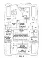
- FIG. 3is a schematic representation of the host vehicle equipped with the on-board unit for conducting two-way wireless communications and a control unit in accordance with the present invention
- FIG. 4is an inside elevational view of a portion of the vehicle's interior that is equipped with the on-board unit for conducting two-way wireless communications in accordance with the present invention
- FIG. 5is a pictorial representation of a screen display of the vehicle's navigation system that is integrated with the on-board unit in accordance with the present invention
- FIG. 6is a schematic representation of the host vehicle on a highway showing a plurality of adjusted zones of interest, each zone of interest corresponding to differing combinations of road conditions, visibility conditions and/or vehicle operating conditions in accordance with the present invention
- FIG. 7is a first flow chart illustrating an overall process executed by the control unit for determining whether or not neighboring vehicles are located within a zone of interest forward from the host vehicle, and whether or not to provide a warning signal to the operator of the host vehicle in response to receiving hard braking signals from neighboring vehicles determined to be within the zone of interest in accordance with the present invention
- FIG. 8is a second flow chart illustrating a portion of the overall process depicted in FIG. 7 executed by the control unit to determine whether or not to adjust dimensions of the zone of interest in accordance with the present invention
- FIG. 9is a third flow chart illustrating another portion of the overall process depicted in FIG. 7 executed by the control unit to determine whether or not to adjust dimensions of the zone of interest in response to weather condition information in accordance with the present invention
- FIG. 10is a fourth flow chart illustrating another portion of the overall process depicted in FIG. 7 executed by the control unit to determine whether or not to adjust dimensions of the zone of interest in response to vehicle operating state information in accordance with the present invention
- FIG. 11is a fifth flow chart illustrating another portion of the overall process depicted in FIG. 7 executed by the control unit to determine whether or not to adjust dimensions of the zone of interest in response to road condition information in accordance with the present invention.
- FIG. 12is a second flow chart illustrating the processing executed by the control unit to determine whether or not to transmit a hard brake warning signal to neighboring vehicles in response to detected hard braking conditions in the host vehicle in accordance with the present invention.
- a two-way wireless communications networkis illustrated in which a host vehicle 10 and several neighboring or nearby vehicles 10 a are each equipped with a vehicle communication system 12 in accordance with a preferred embodiment of the present invention.
- the two-way wireless communications networkalso includes one or more global positioning satellites 14 (only one shown) and one or more roadside units 16 (only two shown) that send and receive signals to and from the vehicles 10 and 10 a .
- the term “host vehicle”refers to a vehicle among a group of DSRC equipped vehicles or vehicles equipped with two-way wireless communications in accordance with the present invention.
- forward vehicle(s)or “preceding vehicle(s)” refers to a vehicle or vehicles equipped with two-way wireless communications that are located in front of the host vehicle
- following vehicle(s)refers to a vehicle or vehicles equipped with two-way wireless communications that are behind the host vehicle relative to its direction of travel.
- neighboring vehiclerefers to DSRC equipped vehicles or vehicles equipped with two-way wireless communications that are located within a communication (broadcasting/receiving) area surrounding the host vehicle in which the host vehicle is capable of either broadcasting a signal to another vehicle within a certain range and/or receiving a signal from another vehicle within a certain range.
- the “host vehicle”is equipped with a forward vehicle brake warning system that provide a warning an operator of the host vehicle 10 that a neighboring vehicle 10 a or forward vehicles in or proximate the path of the host vehicle 10 is currently braking or decelerating at a potentially dangerous rate in accordance with the present invention.
- hard brake signalrefers to a signal sent from one or more of the neighboring vehicles 10 a equipped with DSRC communications indicating that the brakes of the neighboring vehicle(s) have suddenly and/or rapidly been engaged to quickly decrease velocity (decelerate) of the neighboring vehicle(s) 10 a.
- all vehicles equipped with DSRC communicationscan be either the host vehicle 10 or one of the neighboring vehicles 10 a .
- the host vehicle 10is primarily a vehicle that is receiving and processing hard brake signals and neighboring vehicles 10 a are generally vehicles that are likely to transmit a hard brake signal.
- zone of interestrefers to an area forward of the host vehicle 10 that lies along and possibly on either side of a path coinciding with a current direction of travel of the host vehicle 10 .
- the zone of interestis an area that can be periodically, regularly or continuously adjusted and re-dimensioned by the host vehicle 10 in accordance with continuously monitored current road conditions, visibility conditions and/or host vehicle operating conditions.
- a zone of interest 18is indicated in FIG. 1 forward from the vehicle 10 .
- the host vehicle 10processes information in order to adjust and re-dimension the zone of interest 18 as described below.
- the host vehicle 10can receive remotely broadcast weather related information, or can use information provided from sensors on or within the host vehicle 10 in order to adjust and re-dimension the zone of interest 18 .
- the forward vehicle brake warning system 12 of the host vehicle 10is configured and arranged to communicate with and receive signals from other DSRC equipped vehicles 10 a .
- the forward vehicle brake warning system 12 of the host vehicle 10determines whether or not the neighboring vehicle 10 a is located within the current zone of interest 18 , as seen in FIG. 2 . If the neighboring vehicle 10 a is within the zone of interest, a warning action is implemented in order warn the operator of the host vehicle 10 of a potential forward collision event. The warning action is controlled electrically by the forward vehicle brake warning system 12 .
- a “forward collision” as used hereinis defined as an on-road, two or more vehicle collision in which the vehicles are moving forward in the same direction prior to the collision or a collision in which a vehicle in the zone of interest 18 has stopped or is in the process of stopping, having transmitted or broadcast a hard braking signal.
- the forward vehicle brake warning system 12 of the present inventionattempts to warn the operator of the host vehicle 10 of the sudden braking or deceleration of the other vehicle in order to avoid an impending forward collision or at least reduce the likelihood of serious consequences resulting from such a collision.
- the forward vehicle brake warning system 12 of each of the vehicles 10 and 10 acarries out two-way wireless communications between each other as well as with one or more global positioning satellites 14 (only one shown) and one or more roadside units 16 (only one shown).
- the global positioning satellites 14 and the roadside units 16are conventional components that are known in the art.
- the roadside units 16are be equipped with a DSRC unit for broadcasting and receiving signals to the vehicles 10 located with communication (broadcasting/receiving) regions surrounding the roadside units 16 . Since global positioning satellites and roadside units are known in the art, the structures of the global positioning satellites 14 and the roadside units 16 will not be discussed or illustrated in detail herein. Rather, it will be apparent to those skilled in the art from this disclosure that the global positioning satellites 14 and the roadside units 16 can be any type of structure that can be used to carry out the present invention.
- the forward vehicle brake warning system 12is a vehicle on-board unit (OBU) that basically includes a controller or control unit 20 , a two-way wireless communications system 21 , a global positioning system 22 , a navigation system 23 , a map database storage section or component 24 , an optional forward obstacle detection component or system 25 , an array of in-vehicle sensors 26 that communicate sensed information to the control unit 20 via a vehicle bus 28 , and a warning indicator 30 .
- OBUvehicle on-board unit
- control unit 20receives and/or sends various signals to the other component and systems in order to filter messages received from neighboring vehicles 10 a to determine: whether or not one of the received messages is from a neighboring vehicle 10 a ; whether or not that vehicle 10 a is located in the zone of interest 18 , and whether or not that message includes a hard braking signal indicating a possible danger for the host vehicle 10 .
- the control unit 20is configured and/or programmed to carry out this process by executing the steps shown in the flow chart of FIG. 7 (discussed below) in conjunction with various signals to and from the other components and systems. It will be apparent to those skilled in the art from this disclosure that the neighboring or nearby vehicles 10 a are also equipped in a similar or the same manner as the host vehicle 10 and perform similar or the same processes as described herein.
- the control unit 20preferably includes a microcomputer with forward brake warning programming that controls the warning indicator 30 to warn an operator of the host vehicle 10 in response to a hard brake signal or signals received from a neighboring vehicle 10 a within the zone of interest 18 indicating a potential collision event is likely to occur due to the hard braking condition in one or more neighboring vehicle 10 a .
- the control unit 20also preferably includes other conventional components such as an input interface circuit, an output interface circuit, and storage devices such as a ROM (Read Only Memory) device and a RAM (Random Access Memory) device.
- the memory circuitstores processing results and control programs such as ones for operation of the two-way wireless communications system 21 , the global positioning system 22 , the navigation system 23 , the map database storage section 24 , the optional forward obstacle detection component 25 , the in-vehicle sensors 26 and the warning indictor 30 that are run by the processor(s).
- the control unit 20is capable of selectively controlling any of the components of the forward vehicle brake warning system 12 as needed and/or desired. It will be apparent to those skilled in the art from this disclosure that the precise structure and algorithms for the control unit 20 can be any combination of hardware and software that will carry out the functions of the present invention. In other words, “means plus function” clauses as utilized in the specification and claims should include any structure or hardware and/or algorithm or software that can be utilized to carry out the function of the “means plus function” clause.
- the control unit 20preferably includes a program that has an incoming message receiving component or section, an adverse driving condition obtaining component or section, an incoming message relevancy component or section, a relevancy adjustment component or section, a driver warning component or section and a braking condition detection component or section. Based on various signals from the two-way wireless communications system 21 , the global positioning system 22 , the navigation system 23 , the map database storage section 24 , the optional forward obstacle detection component 25 and the in-vehicle sensors 26 , these components or sections will determine whether or not warning action should be implemented by the control unit 20 , such as activation of the warning indicator 30 .
- the control unit 20 of the forward vehicle brake warning system 12is configured to determine whether or not a warning signal should be provided to the operator of the host vehicle 10 by first detecting whether or not a hard braking signal has been received from one or more of the neighboring vehicles 10 a . If a hard braking signal or signals has been received, the control unit 20 performs a process where the zone of interest 18 is adjusted based upon acquired information relating to road conditions, weather conditions and/or vehicle operating conditions.
- the information processed by the control unit 20is provided by one or more of the following: the vehicle parameter identifiers transmitted from the neighboring vehicles 10 a , weather conditions from the roadside units 16 , adverse driving conditions from the roadside units 16 , and/or signals from the array of in-vehicle sensors 26 within the host vehicle 10 .
- the forward vehicle brake warning system 12filters the received signals by determining whether or not the neighboring vehicle 10 a that transmitted the hard braking signal is located within the adjusted zone of interest 18 . If the transmitting vehicle is located within the zone of interest, a warning action is effected to warn the operator or driver of the host vehicle 10 that the forward vehicle or vehicles are currently braking and consequently decelerating at a potentially dangerous rate.
- the two-way wireless communications system 21includes communication interface circuitry that connects and exchanges information with a plurality of the vehicles 10 a that are similarly equipped as well as with the roadside units 16 through a wireless network within the broadcast range of the host vehicle 10 .
- the two-way wireless communications system 21is configured and arranged to conduct direct two way communications between vehicles (vehicle-to-vehicle communications) and roadside units (roadside-to-vehicle communications).
- two-way wireless communications system 21is configured to periodically broadcast a signal in the broadcast area.
- the two-way wireless communication system 21is an on-board unit that has both an omni-directional antenna and a multi-directional antenna.
- the two-way wireless communications system 21is preferably a dedicated short range communications systems, since the latency time between communications is very low compared to most other technologies that are currently available.
- other two-way wireless communications systemscan be used if they are capable of conducting both point-to-point wireless communications and broadcast wireless messages in a limited broadcast area so log as the latency time between communications is short enough.
- the two-way wireless communications system 21is a DSRC system
- the two-way wireless communications system 21will transmit at a 75 Mhz spectrum in a 5.9 GHz band with a data rate of 1 to 54 Mbps, and a maximum range of about 1,000 meters.
- the two-way wireless communications system 21includes seven (7) non-overlapping channels.
- the two-way wireless communications system 21will be assigned a Medium Access Control (MAC) address and/or an IP address so that each vehicle in the network can be individually identified.
- MACMedium Access Control
- the two-way wireless communications system 21is configured to periodically broadcast a standard or common message set (CMS) to the neighboring or nearby vehicles 10 a and the nearby roadside units 16 that within a prescribed broadcast range of the host vehicle 10 .
- This common message set (CMS)would mostly likely be developed such that all of the DSRC equipped vehicles 10 and 10 a would transmit the same type of vehicle parameter identifiers to give relevant kinematical and location information.
- a standardized DSRC message set and data dictionarywould be established for safety applications that utilize vehicle-to-vehicle and/or vehicle-to-infrastructure communications.
- the common message setcan include preset vehicle parameter identifiers, such as a MAC address, an IP address and/or a vehicle ID number, and variable vehicle parameter identifiers indicative of vehicle location and movement such as a GPS location/vehicle position (longitude, latitude and elevation) with a GPS time stamp, a vehicle heading, current braking action(s) and/or a vehicle speed.
- vehicle parameter identifierssuch as a MAC address, an IP address and/or a vehicle ID number
- variable vehicle parameter identifiers indicative of vehicle location and movementsuch as a GPS location/vehicle position (longitude, latitude and elevation) with a GPS time stamp, a vehicle heading, current braking action(s) and/or a vehicle speed.
- the two-way wireless communications system 21is also configured to broadcast a full kinematics message to the neighboring vehicles 10 a and/or a signal that indicates the operational status of the vehicle.
- the message broadcast by the two-way wireless communications system 21can include such information.
- This full kinematics messagecan include the data of the common message set as well as additional relevant kinematics information such as a vehicle type/class, a vehicle size (length, width and weight), a vehicle acceleration, a vehicle brake position, a vehicle throttle position, a vehicle steering wheel angle, current braking action(s) etc.
- the vehicle parameter identifiers including a possible hard brake signalare received and processed by the control unit 20 to determine whether or not sudden hard braking of a forward vehicle is a danger and determine whether or not the operator of the vehicle should be warned of the potential danger.
- This determination of a potential collision eventcan be done in the host vehicle 10 and can be done in neighboring vehicles 10 a receiving the same communications and information.
- the control unit 20evaluates information received and determines an appropriate zone of interest 18 based upon combinations of information, such as received information regarding road conditions, received information regarding weather conditions and host vehicle detected conditions, such as road traction, windshield wiper activity, vehicle speed and headlight usage.
- the control unit 20determines the proximity of the neighboring vehicle 10 a . If the neighboring vehicle 10 a is within the determined zone of interest 18 , a warning action is implemented providing the operator or driver of the host vehicle 10 with an indication of potential danger ahead.
- the global positioning system 22is a conventional global positioning system that is configured and arranged to receive global positioning information of the host vehicle 10 in a conventional manner.
- the global positioning system 22includes a GPS unit 22 A that is a receiver for receiving a signal from the global positioning satellite 14 via and a GPS antenna 22 B.
- the signal transmitted from the global positioning satellite 14is received at regular intervals (e.g. one second) to detect the present position of the host vehicle 10 .
- the GPS unit 22 Apreferably has an accuracy of indicting the actual vehicle position within a few meters or less. This data (present position of the host vehicle 10 ) is fed to the control unit 20 for processing and to the navigation system 23 for processing.
- the navigation system 23is a conventional navigation system that is configured and arranged to receive global positioning information of the host vehicle in a conventional manner.
- the navigation system 23includes a color display unit 23 A and an input controls 23 B.
- the navigation system 23can have its own controller with microprocessor and storage, or the processing for the navigation system 23 can be executed by the control unit 20 . In either case, the signals transmitted from the global positioning satellites 14 are utilized to guide the vehicle 10 in a conventional manner.
- the map database storage section 24configured to store road map data as well as other data that can be associated with the road map data such as various landmark data, fueling station locations, restaurants, etc.
- the map database storage section 24preferably includes a large-capacity storage medium such as a CD-ROM (Compact Disk-Read Only Memory) or IC (Integrated Circuit) card.
- the map database storage section 24is configured to perform a read-out operation of reading out data held in the large-capacity storage medium in response to an instruction from the control unit 20 and/or the navigation system 23 .
- the map database storage section 24is used by the control unit 20 to acquire the map information necessary as needed and or desired for use in predicting a collision.
- the map database storage section 24is also used by the navigation system 23 to acquire the map information necessary for route guiding, map display, and direction guide information display.
- the map information of this embodimentincludes at least information necessary for offering of the map information and route guiding as performed by a general navigation device and necessary for displaying the direction guide information of the embodiment.
- the map informationalso includes at least road links indicating connecting states of nodes, locations of branch points (road nodes), names of roads branching from the branch points, and place names of the branch destinations, and has such a data structure that, by specifying a location of interest, information on the corresponding road and place name can be read.
- the map information of the map database storage section 24stores road information for each road link or node.
- the road information for each road link or nodeincludes identification information of a road such as a road name, attribute information (road type—local road, unrestricted access, restricted access, bridge, tunnel, roundabout, etc.), a road width or number of lanes, a connection angle of a road at a branch point, and etc,
- the global positioning system 22can be use together with the navigation system 23 and/or the map database storage section 24 to enhance the accuracy of the data and local weather information.
- the array of in-vehicle sensors 26are configured to monitor various devices, mechanisms and systems within the host vehicle 10 and provide information relating to the status of those devices, mechanisms and systems to the control unit 20 .
- the in-vehicle sensors 26are connected to a traction control system 40 , a windshield wiper motor 42 or wiper motor controller (not shown), a headlight controller 44 , a speedometer 46 and/or a braking system 48 .
- the control unit 20 of the forward vehicle brake warning system 12operates and processes information as follows.
- the incoming message receiving component of the control unit 20processes signals and messages from the two-way wireless communications system 21 received from the roadside units 16 and the neighboring vehicles 10 a that are within transmission receiving distance. All the information in the messages and signals is provided to and stored by the control unit 20 for processing.
- the adverse driving condition obtaining component of the control unit 20processes signals and messages from the two-way wireless communications system 21 received from the roadside units 16 to obtain weather related information and/or road condition related information designating road and/or visibility conditions.
- Road conditionscan include such information as icy, rainy, wet, snow covered, etc.
- Visibility conditionscan include foggy, precipitation limiting visibility, dark, etc.
- the control unit 20correlates the received road and/or weather information using the global positioning system 22 and navigation system 23 to confirm that the local weather and/or road condition information is relevant to the location of the host vehicle 10 .
- the relevancy adjustment component of the control unit 20is configured to adjust a relevancy determination to selectively filter the hard brake messages received depending upon received or determined adverse driving condition information.
- the relevancy adjustment componentis configured to adjust the relevancy determination by selectively adjusting the dimensions of the prescribed zone of interest.
- the dimensions of the zone of interestcan be changed using factors such as road conditions, weather conditions and or vehicle operating conditions.
- the dimensions of the zone of interest 18can be adjusted based upon a detected host vehicle speed.
- FIG. 6shows a host vehicle 10 an initial or default zone of interest 18 a and several of many possible zones of interest 18 b , 18 c and 18 d .
- the zones of interest shown in FIG. 6are merely a few examples of many differing size and shapes of the zone of interest.
- the shape and dimensions of the zone of interestare determined by various factors, as explained below.
- the initial or default zone of interest 18 ahas a first maximum ahead distance D 1 where the first maximum ahead distance D 1 represents an area forward or in front of the host vehicle along a current path or trajectory of the host vehicle.
- the dimensions of the zone of interestcan, for example, be increase to have a maximum ahead distance D 2 , D 3 or D 4 depending upon a detected the speed of the host vehicle 10 .
- the relevancy adjustment component of the control unit 20is configured to adjust the relevancy determination by selectively changing the maximum ahead distance of the prescribed zone of interest relative to the host vehicle when the adverse driving condition obtaining component determines a visibility impaired road condition. Specifically, if visibility is reduce by, for instance, rain, snow or fog, the zone of interest 18 a can be revised from having a maximum ahead distance D 1 to having a maximum ahead distance ahead distance D 2 , D 3 or D 4 , as shown in FIG. 6 .
- the relevancy adjustment componentis further configured to adjust the relevancy determination by selectively changing a minimum ahead distance of the prescribed zone of interest 18 relative to the host vehicle 10 . Examples of minimum ahead distances M 1 , M 2 and M 3 are shown in FIG. 6 , although it should be understood that the minimum ahead distance is variable.
- the relevancy adjustment componentis further configured to adjust the relevancy determination by selectively changing a lateral angle of view of the prescribed zone of interest 18 relative to the host vehicle. For instance as shown in FIG. 6 , an initial lateral angle of view ⁇ 1 , can be increased to lateral angle of view ⁇ 2 or lateral angle of view ⁇ 3 when the adverse driving condition obtaining component determines a low friction road condition. It should be understood that combinations of adjustments are made in response to a variety of information either received or detected. It should also be understood that the examples given above and in FIG. 6 of the minimum and maximum distances and the lateral angles are demonstrations of the possible adjustments made by the control unit 20 to the zone of interest 18 , and are not meant to limit the zone of interest to a specific shape or configuration. In other words, the determined or adjusted dimensions of the zone of interest 18 depend upon the various data processed, as described above, and appropriate safety concerns, such as, for example, weight of the host vehicle 10 , tire traction and relative stopping distances for various speeds of the host vehicle 10
- the incoming message relevancy componentis configured to perform a relevancy determination of the hard brake messages received based on whether the hard brake messages received are from neighboring vehicles 10 a that are within the prescribed zone of interest 18 in front of the host vehicle 10 . If the neighboring vehicle is located within the zone of interest, then a driver warning is issued by the control unit 20 .
- the driver warning component of the control unit 20is configured to alert the driver of the host vehicle based upon the relevancy determination by the incoming message relevancy component.
- the driver warning componentcan be configured in any one of a variety of ways. For instance, driver warning component can be configured to produce an audible warning signal to alert the driver. The driver warning component can alternatively be configured to produce a haptic warning signal to alert the driver. The driver warning component can also be configured to produce a visual warning signal to alert the driver
- a buzzer or alarmcan be connected to the control unit 20 to emit a loud warning sound either alone or in concert with other warning signals.
- a light in the dashboard 52 (shown in FIG. 4 ) of the host vehicle 10can light up to alert the operator of the host vehicle 10 .
- a printed messagecan appear on the display 23 A ( FIGS. 3 , 4 and 5 ) on the dashboard 52 alerting the operator or driver to an imminent danger ahead either alone or in concert with other warning signals.
- a steering wheel 56can be adapted to vibrate in order to provide a warning signal to the operator or driver of the host vehicle 10 either alone or in concert with other warning signals.
- the control unit 20can alternatively activate various vehicle subsystems 38 ( FIG. 3 ) in a coordinated effort to mitigate occupant injuries during a collision based on the information received.
- the braking condition detection componentis configured to detect a hard brake condition or operation in the host vehicle. If the brakes 48 within the vehicle have been aggressively applied, the two-way wireless communications system 21 (a communication component) broadcasts a hard brake message to the neighboring vehicles located within the prescribed communication region around the host vehicle.
- FIG. 7one possible process that can be executed by the control unit 20 to carry out the present invention will now be discussed.
- the stepsare preferably being performed by the control unit 20 of the host vehicle 10 , along with various other apparatus and mechanisms within the vehicle 10 .
- step S 1the control unit 20 begins the process, preferably as the host vehicle 10 is set in motion.
- step S 2the control unit 20 is configured to instruct the two-way wireless communications system 21 of the host vehicle 10 to monitor incoming messages and identify those messages that include any of signals corresponding to the common message set with current vehicle parameter identifiers from neighboring vehicles 10 a , as discussed above, as well as its MAC address and/or IP address.
- the common message setcan include a hard brake message indicating that the transmitting neighboring vehicle 10 a is currently braking.
- the neighboring vehicle 10 a transmitting such signal(s)is within the prescribed communication region around the host vehicle 10 and is equipped with the forward vehicle brake warning system 12 of the present invention.
- Step S 2at least partially represents the incoming message receiving component of the host vehicle 10 . Then the processing executed by the control unit 20 of the host vehicle 10 proceeds to step S 3 .
- step S 3the control unit 20 monitors incoming road and/or weather information remotely broadcasted or transmitted by one or both of the satellites 14 and the roadside units 16 and received via the two-way wireless communications system 21 and/or the global positioning system 22 .
- the information receivedcan be weather related information and/or road condition related information designating conditions such as icy, rainy, wet, snow covered, etc.
- the control unit 20correlates the received road and/or weather information using the global positioning system 22 and navigation system 23 to confirm that the local weather and/or road condition information is relevant to the location of the host vehicle 10 .
- the operations performed in step S 3at least partially represent the adverse driving condition obtaining component of the host vehicle 10 .
- step S 4the control unit 20 monitors the various conditions detected by each of the in-vehicle sensors 26 .
- the in-vehicle sensors 26can be connected to any of a variety of mechanical and electrical systems within the vehicle, such as the traction control system 40 , the windshield wiper motor 42 , the headlight controller 44 and/or the speedometer 46 . Consequently, the control unit 20 can be provided with information concerning one or more of the following: road traction conditions from the traction control system 40 , rain conditions from the speed and duration of use of the windshield wiper motor 42 , whether it is dark or not from the headlight controller 44 and/or the relative speed of the host vehicle 10 from the speedometer 46 .
- step S 4 by the control unit 20also at least partially represent the adverse driving condition obtaining component and a host vehicle operating state section of the host vehicle 10 .
- the host vehicle operating state sectionmonitors the various systems of the host vehicle 10 and provides a signal or information indicative of the host vehicle operating state for subsequent use by the control unit 20 .
- step S 5the control unit 20 determines whether or not the messages received in step S 2 included any hard brake signals or warning messages from neighboring vehicle(s) 10 a . If no such messages have been received, then the control unit 20 returns to steps S 2 , S 3 and S 4 . If in step S 5 such a message has been received, then the control unit 20 moves to step S 6 .
- step S 6the control unit 20 is configured to determine whether or not any adverse conditions relating to road or weather conditions have been perceived via the information received in any of steps S 2 , S 3 or S 4 . If adverse conditions are present, the control unit 20 moves to step S 7 , where message filtering or relevancy adjustment can be made.
- the message filtering performed in step S 7can implement, for example, re-evaluation and re-sizing of the zone of interest 18 .
- the operations performed in step S 7are described in greater detail below with respect to FIGS. 8-11 .
- step S 6if no adverse conditions are perceived, then operations of the control unit 20 move to step S 8 .
- step S 8the control unit 20 determines whether or not the hard braking condition signal received from neighboring vehicle(s) 10 a is relevant or not. Specifically, the control unit 20 determines whether the neighboring vehicle(s) 10 a that transmitted the hard braking condition signal is located within the prescribed zone of interest 10 . If neighboring vehicle 10 a that sent the hard brake condition signal is located within the zone of interest, then operations of the control unit 20 move to step S 9 .
- the operations of the control unit 20 at step S 8at least partially represent the incoming message relevancy component of the present invention.
- the incoming message relevancy componentis configured to perform a relevancy determination of the hard brake messages received based on whether the hard brake messages received are from neighboring vehicles 10 a that are within the prescribed zone of interest 18 in front of the host vehicle 10 .
- the control unit 20implements a warning action by providing instructions to the warning indicator 30 to start a warning action.
- the warning actioncan include any of a variety of actions as described above. Operations in either or both of steps S 8 and S 9 at least partially correspond to the driver warning component of the present invention.
- step S 8if the control unit 20 determines that the neighboring vehicle 10 a that transmitted the hard brake condition signal is not located within the prescribed zone of interest 10 , then operations return again to steps S 2 , S 3 and S 4 .
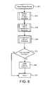
- FIG. 8the operations of the control unit 20 at step S 7 in FIG. 7 are now described in greater detail.
- step S 11the relevancy adjustment process begins.
- step S 12all weather condition information, in particular, information that relates to visibility conditions and traction (road) conditions is processed as further described below with reference to FIG. 9 .
- step S 13all vehicle operating state information, in particular, information that relates to visibility conditions, speed and traction (road) conditions is processed as further described below with reference to FIG. 10 .
- step S 14all road condition information, in particular, information that relates to traction (road) conditions and visibility conditions is processed as further described below with reference to FIG. 11 .
- step S 12 in FIG. 8The process represented at step S 12 in FIG. 8 is now described in greater detail below with reference to FIG. 9 .
- step S 20 in FIG. 9a process is begun that evaluates received weather condition related information.
- a determinationis made at step S 21 whether or not received weather related information indicates visibility impairing conditions. If visibility impairing conditions are likely present, operations move to step S 22 where an indication is put in memory that the zone of interest should be re-dimensioned by increasing the maximum ahead view distance. If visibility impairing conditions are not present in step S 21 , operations move to step S 23 .
- step S 23a determination is made whether or not received weather related information indicates traction impairing conditions.
- step S 24If traction impairing conditions are likely present, operations move to step S 24 where an indication is put in memory the zone of interest should be re-dimensioned by increasing the angle of view. If traction impairing conditions are not present in step S 23 , operations move to step S 25 . At step S 25 other conditions can be considered and if such conditions are present appropriate adjustments to the zone of interest can be indicated in memory at step S 26 . At step 27 , operations return to FIG. 8 and proceed to step S 13 .
- step S 30 in FIG. 10a process is begun that evaluates host vehicle operating state related information.
- step S 33a determination is made whether or not the host vehicle speed has changed.
- step S 34an indication is put into memory that the zone of interest should be re-dimensioned by increasing or decreasing the minimum and/or maximum ahead view distances. If the speed has increased the maximum ahead view distance can be increased. If the speed decreases, the maximum ahead view distance can be decreased. If the host vehicle speed has not changed, operations move to step S 35 .
- step S 35a determination is made whether or not the traction control system 40 is experiencing traction slippage. If traction impairing conditions are present, operations move to step S 36 where an indication is put into memory that the zone of interest should be re-dimensioned by increasing the angle of view. If traction impairing conditions are not present in step S 35 , operations move to step S 37 . At step S 37 other conditions can be considered and if such conditions are present appropriate adjustments to the zone of interest can be made at step S 38 . At step 39 , operations return to FIG. 8 and proceed to step S 14 .
- step S 14 in FIG. 8The process represented at step S 14 in FIG. 8 is now described in greater detail below with reference to FIG. 11 .
- step S 40 in FIG. 11a process is begun that evaluates received road condition related information (for example, as received from transmissions from the roadside units 16 ).
- a determinationis made at step S 41 whether or not received road related information is traction impairment information. If traction impairment information has been received, operations move to step S 42 where an indication is put into memory that the zone of interest should be re-dimensioned by increasing the angle of view.
- step 43a determination is made whether or not received road related information is visibility impairment information.
- step S 44If visibility impairment information has been received, operations move to step S 44 where an indication is put into memory that the zone of interest should be re-dimensioned by increasing the maximum ahead view distance. At step S 45 other information can be considered and if such information is received and appropriate adjustments to the zone of interest are necessary, such adjustments are recorded in memory at step S 46 . At step 47 , operations return to FIG. 8 and proceed to step S 15 .
- step S 50the process begins.
- the control unit 20monitors various conditions within the host vehicle 10 . Among other parameters, the control unit 20 monitors the condition of the brakes 48 .
- step S 52if a hard braking condition is detected in the brakes 48 , operations move to step S 53 where a hard brake signal is transmitted to neighboring vehicles 10 a . If no hard brake condition is present in step S 52 , operations move to step S 54 where a current status message composed from the common message set is transmitted to neighboring vehicles 10 a .
- the operations carried out in FIG. 12preferably continue in parallel (at the same time) as the operations described above with respect to FIGS. 8-11 .
- the following directional terms “forward, rearward, above, downward, vertical, horizontal, below and transverse” as well as any other similar directional termsrefer to those directions of a vehicle equipped with the present invention. Accordingly, these terms, as utilized to describe the present invention should be interpreted relative to a vehicle equipped with the present invention.
- the terms of degree such as “substantially”, “about” and “approximately” as used hereinmean a reasonable amount of deviation of the modified term such that the end result is not significantly changed. For example, these terms can be construed as including a deviation of at least ⁇ 5% of the modified term if this deviation would not negate the meaning of the word it modifies.
Landscapes
- Physics & Mathematics (AREA)
- General Physics & Mathematics (AREA)
- Business, Economics & Management (AREA)
- Emergency Management (AREA)
- Traffic Control Systems (AREA)
Abstract
Description
Claims (30)
Priority Applications (2)
| Application Number | Priority Date | Filing Date | Title |
|---|---|---|---|
| US11/280,403US7486199B2 (en) | 2005-11-17 | 2005-11-17 | Forward vehicle brake warning system |
| US12/337,169US8854198B2 (en) | 2005-11-17 | 2008-12-17 | Forward vehicle brake warning system |
Applications Claiming Priority (1)
| Application Number | Priority Date | Filing Date | Title |
|---|---|---|---|
| US11/280,403US7486199B2 (en) | 2005-11-17 | 2005-11-17 | Forward vehicle brake warning system |
Related Child Applications (1)
| Application Number | Title | Priority Date | Filing Date |
|---|---|---|---|
| US12/337,169ContinuationUS8854198B2 (en) | 2005-11-17 | 2008-12-17 | Forward vehicle brake warning system |
Publications (2)
| Publication Number | Publication Date |
|---|---|
| US20070109146A1 US20070109146A1 (en) | 2007-05-17 |
| US7486199B2true US7486199B2 (en) | 2009-02-03 |
Family
ID=38040218
Family Applications (2)
| Application Number | Title | Priority Date | Filing Date |
|---|---|---|---|
| US11/280,403Active2026-04-26US7486199B2 (en) | 2005-11-17 | 2005-11-17 | Forward vehicle brake warning system |
| US12/337,169ActiveUS8854198B2 (en) | 2005-11-17 | 2008-12-17 | Forward vehicle brake warning system |
Family Applications After (1)
| Application Number | Title | Priority Date | Filing Date |
|---|---|---|---|
| US12/337,169ActiveUS8854198B2 (en) | 2005-11-17 | 2008-12-17 | Forward vehicle brake warning system |
Country Status (1)
| Country | Link |
|---|---|
| US (2) | US7486199B2 (en) |
Cited By (39)
| Publication number | Priority date | Publication date | Assignee | Title |
|---|---|---|---|---|
| US20090096598A1 (en)* | 2005-11-17 | 2009-04-16 | Nissan Technical Center North America, Inc. | Forward vehicle brake warning system |
| US20090207043A1 (en)* | 2008-02-20 | 2009-08-20 | Ford Global Technologies, Inc | Wireless, infrastructureless communication system for vehicles and method for the same |
| US20090237291A1 (en)* | 2008-03-21 | 2009-09-24 | Denso Corporation | Recognition system for vehicle |
| US20090237293A1 (en)* | 2008-03-21 | 2009-09-24 | Denso Corporation | Recognition system for vehicle |
| US20100245123A1 (en)* | 2009-03-27 | 2010-09-30 | Ford Global Technologies, Llc | Telematics system and method for traction reporting and control in a vehicle |
| US20110112720A1 (en)* | 2009-11-09 | 2011-05-12 | Dale Keep | Road Conditions Reporting |
| US20110238306A1 (en)* | 2010-03-26 | 2011-09-29 | Honda Motor Co., Ltd. | Method Of Determining Absolute Position For A Motor Vehicle |
| US20110301825A1 (en)* | 2010-06-03 | 2011-12-08 | Polaris Industries Inc. | Electronic throttle control |
| US8335643B2 (en) | 2010-08-10 | 2012-12-18 | Ford Global Technologies, Llc | Point of interest search, identification, and navigation |
| US20130151058A1 (en)* | 2011-12-09 | 2013-06-13 | GM Global Technology Operations LLC | Method and system for controlling a host vehicle |
| US8483958B2 (en) | 2010-12-20 | 2013-07-09 | Ford Global Technologies, Llc | User configurable onboard navigation system crossroad presentation |
| US8521424B2 (en) | 2010-09-29 | 2013-08-27 | Ford Global Technologies, Llc | Advanced map information delivery, processing and updating |
| US8688321B2 (en) | 2011-07-11 | 2014-04-01 | Ford Global Technologies, Llc | Traffic density estimation |
| US8731814B2 (en) | 2010-07-02 | 2014-05-20 | Ford Global Technologies, Llc | Multi-modal navigation system and method |
| US8838385B2 (en) | 2011-12-20 | 2014-09-16 | Ford Global Technologies, Llc | Method and apparatus for vehicle routing |
| US8849552B2 (en) | 2010-09-29 | 2014-09-30 | Ford Global Technologies, Llc | Advanced map information delivery, processing and updating |
| US8878660B2 (en) | 2011-06-28 | 2014-11-04 | Nissan North America, Inc. | Vehicle meter cluster |
| US8977479B2 (en) | 2013-03-12 | 2015-03-10 | Ford Global Technologies, Llc | Method and apparatus for determining traffic conditions |
| US9047774B2 (en) | 2013-03-12 | 2015-06-02 | Ford Global Technologies, Llc | Method and apparatus for crowd-sourced traffic reporting |
| US9374661B2 (en) | 2012-04-02 | 2016-06-21 | University Of Washington Through Its Center For Commercialization | Travel pattern discovery using mobile device sensors |
| US9454905B2 (en) | 2013-04-29 | 2016-09-27 | Global Foundries Inc. | Safe distance determination |
| CN106157667A (en)* | 2016-08-12 | 2016-11-23 | 江苏大学 | A kind of expressway traffic accident early warning system based on mobile phone A PP |
| US9713963B2 (en) | 2013-02-18 | 2017-07-25 | Ford Global Technologies, Llc | Method and apparatus for route completion likelihood display |
| US9713956B2 (en) | 2015-03-05 | 2017-07-25 | Honda Motor Co., Ltd. | Vehicle-to-vehicle communication system providing a spatiotemporal look ahead and method thereof |
| US9846046B2 (en) | 2010-07-30 | 2017-12-19 | Ford Global Technologies, Llc | Vehicle navigation method and system |
| US9863777B2 (en) | 2013-02-25 | 2018-01-09 | Ford Global Technologies, Llc | Method and apparatus for automatic estimated time of arrival calculation and provision |
| US9874452B2 (en) | 2013-03-14 | 2018-01-23 | Ford Global Technologies, Llc | Method and apparatus for enhanced driving experience including dynamic POI identification |
| US10173674B2 (en) | 2016-06-15 | 2019-01-08 | Ford Global Technologies, Llc | Traction based systems and methods |
| DE102019125515A1 (en)* | 2019-06-28 | 2020-12-31 | Marco Scheffler | Braking device for a vehicle |
| US20210284152A1 (en)* | 2020-03-11 | 2021-09-16 | Honda Motor Co., Ltd. | Vehicle and control device of the same |
| US11288521B2 (en)* | 2019-01-31 | 2022-03-29 | Uatc, Llc | Automated road edge boundary detection |
| US11673570B2 (en) | 2021-04-26 | 2023-06-13 | Nissan North America, Inc. | Vehicle driving behavior monitoring and warning system |
| US11878678B2 (en) | 2016-11-18 | 2024-01-23 | Polaris Industries Inc. | Vehicle having adjustable suspension |
| US11904648B2 (en) | 2020-07-17 | 2024-02-20 | Polaris Industries Inc. | Adjustable suspensions and vehicle operation for off-road recreational vehicles |
| US11912096B2 (en) | 2017-06-09 | 2024-02-27 | Polaris Industries Inc. | Adjustable vehicle suspension system |
| US11919524B2 (en) | 2014-10-31 | 2024-03-05 | Polaris Industries Inc. | System and method for controlling a vehicle |
| US11970036B2 (en) | 2012-11-07 | 2024-04-30 | Polaris Industries Inc. | Vehicle having suspension with continuous damping control |
| US11975584B2 (en) | 2018-11-21 | 2024-05-07 | Polaris Industries Inc. | Vehicle having adjustable compression and rebound damping |
| US12397878B2 (en) | 2020-05-20 | 2025-08-26 | Polaris Industries Inc. | Systems and methods of adjustable suspensions for off-road recreational vehicles |
Families Citing this family (43)
| Publication number | Priority date | Publication date | Assignee | Title |
|---|---|---|---|---|
| US20050220637A1 (en) | 2004-04-01 | 2005-10-06 | Hydro-Gear Limited Partnership | Fan shroud for pump |
| US8694328B1 (en)* | 2006-12-14 | 2014-04-08 | Joseph Gormley | Vehicle customization and personalization activities |
| JP2008275460A (en)* | 2007-04-27 | 2008-11-13 | Mitsubishi Electric Corp | Radar equipment |
| DE102007056354A1 (en)* | 2007-11-16 | 2009-05-20 | Bayerische Motoren Werke Aktiengesellschaft | Data exchange between two or more vehicles, which is associated with identification information |
| US20090228172A1 (en)* | 2008-03-05 | 2009-09-10 | Gm Global Technology Operations, Inc. | Vehicle-to-vehicle position awareness system and related operating method |
| US8466810B2 (en) | 2008-05-30 | 2013-06-18 | Navteq B.V. | Data mining in a digital map database to identify intersections located at hill bottoms and enabling precautionary actions in a vehicle |
| DE102008040986A1 (en)* | 2008-08-05 | 2010-02-11 | Evonik Goldschmidt Gmbh | Hydrophobization of mineral fiber components |
| US7973674B2 (en)* | 2008-08-20 | 2011-07-05 | International Business Machines Corporation | Vehicle-to-vehicle traffic queue information communication system and method |
| KR101013121B1 (en)* | 2008-12-17 | 2011-02-14 | 고려대학교 산학협력단 | Inter-vehicle wireless communication device and method |
| US9230419B2 (en) | 2010-07-27 | 2016-01-05 | Rite-Hite Holding Corporation | Methods and apparatus to detect and warn proximate entities of interest |
| DE102010054080B4 (en) | 2010-12-10 | 2024-12-12 | Volkswagen Ag | Relevance Assessment in a Car2X Network |
| US8643505B2 (en)* | 2011-06-01 | 2014-02-04 | Nissan North America, Inc. | Host vehicle with externally perceivable cruise control indicating device |
| US20130083061A1 (en)* | 2011-09-30 | 2013-04-04 | GM Global Technology Operations LLC | Front- and rear- seat augmented reality vehicle game system to entertain & educate passengers |
| DE102012210059A1 (en) | 2012-06-14 | 2013-12-19 | Continental Automotive Gmbh | Method for verifying and / or preprocessing data packets and for implementing the method set up control device |
| JP5910521B2 (en)* | 2013-01-25 | 2016-04-27 | トヨタ自動車株式会社 | Dangerous location notification system, driving support device, and driving support method |
| US9153116B2 (en)* | 2013-09-09 | 2015-10-06 | International Business Machines Corporation | Real-time vehicle driver performance monitoring |
| US20150100189A1 (en)* | 2013-10-07 | 2015-04-09 | Ford Global Technologies, Llc | Vehicle-to-infrastructure communication |
| US9435652B2 (en)* | 2013-12-19 | 2016-09-06 | Novatel Wireless, Inc. | Dynamic routing intelligent vehicle enhancement system |
| US10065562B2 (en)* | 2013-12-31 | 2018-09-04 | International Business Mahcines Corporation | Vehicle collision avoidance |
| US9779623B2 (en)* | 2014-07-02 | 2017-10-03 | Lenovo Enterprise Solutions (Singapore) Pte. Ltd. | Communication of alerts to vehicles based on vehicle movement |
| KR101617543B1 (en)* | 2014-10-06 | 2016-05-02 | 주식회사 만도 | Detecting system for vehicle emergency |
| US20160321924A1 (en)* | 2015-05-01 | 2016-11-03 | Hyundai America Technical Center, Inc. | Predictive road hazard identification system |
| US10419723B2 (en)* | 2015-06-25 | 2019-09-17 | Magna Electronics Inc. | Vehicle communication system with forward viewing camera and integrated antenna |
| EP3151216A1 (en)* | 2015-10-01 | 2017-04-05 | Volvo Car Corporation | Method for providing an alert to a driver and an alert system |
| US10201416B2 (en) | 2016-05-16 | 2019-02-12 | Boston Scientific Scimed, Inc. | Replacement heart valve implant with invertible leaflets |
| DE102016217491A1 (en)* | 2016-09-14 | 2018-03-15 | Siemens Aktiengesellschaft | Method for detecting oncoming vehicles |
| KR101989102B1 (en)* | 2017-09-13 | 2019-06-13 | 엘지전자 주식회사 | Driving assistance Apparatus for Vehicle and Control method thereof |
| CN107600076B (en)* | 2017-09-18 | 2020-05-26 | 北京汽车集团有限公司 | Vehicle anti-collision prompting method and device, storage medium and vehicle |
| DE102017222320A1 (en) | 2017-12-08 | 2019-06-13 | Continental Automotive Gmbh | Tachograph arrangement and method for operating a tachograph arrangement |
| US20190287394A1 (en) | 2018-03-19 | 2019-09-19 | Derq Inc. | Early warning and collision avoidance |
| JP6964278B2 (en)* | 2018-04-02 | 2021-11-10 | パナソニックIpマネジメント株式会社 | Driving support device |
| US10580298B1 (en)* | 2018-09-11 | 2020-03-03 | Toyota Research Institute, Inc. | Self-driving infrastructure |
| US11001200B2 (en)* | 2019-05-30 | 2021-05-11 | Nissan North America, Inc. | Vehicle occupant warning system |
| JP2022546320A (en) | 2019-08-29 | 2022-11-04 | ディーイーアールキュー インコーポレイテッド | Advanced in-vehicle equipment |
| WO2021065480A1 (en)* | 2019-09-30 | 2021-04-08 | 京セラ株式会社 | Base station, traffic communication system, and traffic communication method |
| DE102020210238A1 (en)* | 2020-08-12 | 2022-02-17 | Robert Bosch Gesellschaft mit beschränkter Haftung | Method for warning road users with monitoring of the surroundings of a vehicle that is in operation and device for carrying out the method |
| US11749105B2 (en)* | 2020-10-01 | 2023-09-05 | Magna Electronics Inc. | Vehicular communication system with turn signal identification |
| JP7512883B2 (en)* | 2020-12-22 | 2024-07-09 | トヨタ自動車株式会社 | Information processing device, information processing method, and program |
| US11639181B2 (en) | 2021-09-29 | 2023-05-02 | Nissan North America, Inc. | Lead vehicle braking warning system |
| KR102831105B1 (en)* | 2022-02-17 | 2025-07-08 | 주식회사 에이치엘클레무브 | Controlling system of vehicle and controlling method thereof |
| KR20230134165A (en)* | 2022-03-11 | 2023-09-21 | 현대자동차주식회사 | Apparatus for controlling autonomous driving and method thereof |
| CN115257739A (en)* | 2022-09-30 | 2022-11-01 | 南通艾美瑞智能制造有限公司 | Front vehicle following method capable of self-adaptively adjusting speed |
| CN116916254B (en)* | 2023-09-13 | 2023-12-22 | 深圳市广和通无线通信软件有限公司 | Vehicle safety prompting method and device based on man-machine interaction |
Citations (23)
| Publication number | Priority date | Publication date | Assignee | Title |
|---|---|---|---|---|
| US6121896A (en)* | 1999-01-26 | 2000-09-19 | Rahman; Anis | Motor vehicle early warning system |
| US20020101337A1 (en)* | 2000-11-24 | 2002-08-01 | Toyota Jidosha Kabushiki Kaisha | Vehicle warning apparatus for generating warning signal depending upon operator's brake operating characteristics |
| US20020105423A1 (en)* | 2000-12-05 | 2002-08-08 | Rast Rodger H. | Reaction advantage anti-collision systems and methods |
| US20020198660A1 (en)* | 2001-06-26 | 2002-12-26 | Medius, Inc. | Method and apparatus for transferring information between vehicles |
| US20030060980A1 (en)* | 2001-09-21 | 2003-03-27 | Prakah-Asante Kwaku O. | Integrated collision prediction and safety systems control for improved vehicle safety |
| US20030102997A1 (en)* | 2000-02-13 | 2003-06-05 | Hexagon System Engineering Ltd. | Vehicle communication network |
| US20030128112A1 (en)* | 2002-01-09 | 2003-07-10 | Cho-Ki Chow | Wireless speed indicating system of automobile |
| US20030141452A1 (en)* | 2002-01-29 | 2003-07-31 | Musiel Michael J. | Object detection apparatus |
| US6731925B2 (en)* | 2001-10-24 | 2004-05-04 | Mouhamad Ahmad Naboulsi | Safety control system for vehicles |
| US20040119634A1 (en)* | 2002-12-19 | 2004-06-24 | Yoshie Samukawa | Obstacle detection system for automotive vehicle |
| US6765495B1 (en)* | 2000-06-07 | 2004-07-20 | Hrl Laboratories, Llc | Inter vehicle communication system |
| US6798354B2 (en)* | 2000-02-18 | 2004-09-28 | Daimlerchrysler Ag | Device for warning the driver of a motor vehicle of dangers by radio |
| US6819234B1 (en)* | 2003-05-13 | 2004-11-16 | Lawrence Bunker | Vehicle braking system safety enhancements |
| US20040245853A1 (en)* | 2003-05-22 | 2004-12-09 | Pioneer Corporation | Harsh braking warning system and method, vehicle warning apparatus and method utilizing same, information transmitting apparatus and method utilizing the system and method, server apparatus, program for the system and information recording medium for such a program |
| US20040254728A1 (en)* | 2002-10-25 | 2004-12-16 | Poropat George Vladimir | Collision warning system and method |
| US20050122251A1 (en)* | 2003-12-09 | 2005-06-09 | Nissan Motor Co., Ltd. | Preceding-vehicle detecting apparatus, own-vehicle controlling apparatus, and preceding-vehicle detecting method |
| US20050218564A1 (en)* | 2004-04-01 | 2005-10-06 | Nahill Thomas E | Multilayer container trimming |
| US20060114123A1 (en)* | 2002-09-03 | 2006-06-01 | Daimlerchrysler | Device and method for radio-based danger warning |
| US20060155469A1 (en)* | 2003-07-11 | 2006-07-13 | Tomoya Kawasaki | Crash-safe vehicle control system |
| US7124027B1 (en)* | 2002-07-11 | 2006-10-17 | Yazaki North America, Inc. | Vehicular collision avoidance system |
| US20070008095A1 (en)* | 2005-06-09 | 2007-01-11 | Gwinn H S M | Intelligent brake light system |
| US20070080829A1 (en)* | 2003-06-30 | 2007-04-12 | Daimlerchrysler Ag | Method and apparatus in a vehicle for producing and wirelessly transmitting messages to other vehicles |
| US7206686B2 (en)* | 2003-11-10 | 2007-04-17 | Honda Motor Co., Ltd. | System and method for detecting an object ahead of a vehicle and controlling the vehicle in response to the detected object |
Family Cites Families (1)
| Publication number | Priority date | Publication date | Assignee | Title |
|---|---|---|---|---|
| US7486199B2 (en)* | 2005-11-17 | 2009-02-03 | Nissan Technical Center North America, Inc. | Forward vehicle brake warning system |
- 2005
- 2005-11-17USUS11/280,403patent/US7486199B2/enactiveActive
- 2008
- 2008-12-17USUS12/337,169patent/US8854198B2/enactiveActive
Patent Citations (23)
| Publication number | Priority date | Publication date | Assignee | Title |
|---|---|---|---|---|
| US6121896A (en)* | 1999-01-26 | 2000-09-19 | Rahman; Anis | Motor vehicle early warning system |
| US20030102997A1 (en)* | 2000-02-13 | 2003-06-05 | Hexagon System Engineering Ltd. | Vehicle communication network |
| US6798354B2 (en)* | 2000-02-18 | 2004-09-28 | Daimlerchrysler Ag | Device for warning the driver of a motor vehicle of dangers by radio |
| US6765495B1 (en)* | 2000-06-07 | 2004-07-20 | Hrl Laboratories, Llc | Inter vehicle communication system |
| US20020101337A1 (en)* | 2000-11-24 | 2002-08-01 | Toyota Jidosha Kabushiki Kaisha | Vehicle warning apparatus for generating warning signal depending upon operator's brake operating characteristics |
| US20020105423A1 (en)* | 2000-12-05 | 2002-08-08 | Rast Rodger H. | Reaction advantage anti-collision systems and methods |
| US20020198660A1 (en)* | 2001-06-26 | 2002-12-26 | Medius, Inc. | Method and apparatus for transferring information between vehicles |
| US20030060980A1 (en)* | 2001-09-21 | 2003-03-27 | Prakah-Asante Kwaku O. | Integrated collision prediction and safety systems control for improved vehicle safety |
| US6731925B2 (en)* | 2001-10-24 | 2004-05-04 | Mouhamad Ahmad Naboulsi | Safety control system for vehicles |
| US20030128112A1 (en)* | 2002-01-09 | 2003-07-10 | Cho-Ki Chow | Wireless speed indicating system of automobile |
| US20030141452A1 (en)* | 2002-01-29 | 2003-07-31 | Musiel Michael J. | Object detection apparatus |
| US7124027B1 (en)* | 2002-07-11 | 2006-10-17 | Yazaki North America, Inc. | Vehicular collision avoidance system |
| US20060114123A1 (en)* | 2002-09-03 | 2006-06-01 | Daimlerchrysler | Device and method for radio-based danger warning |
| US20040254728A1 (en)* | 2002-10-25 | 2004-12-16 | Poropat George Vladimir | Collision warning system and method |
| US20040119634A1 (en)* | 2002-12-19 | 2004-06-24 | Yoshie Samukawa | Obstacle detection system for automotive vehicle |
| US6819234B1 (en)* | 2003-05-13 | 2004-11-16 | Lawrence Bunker | Vehicle braking system safety enhancements |
| US20040245853A1 (en)* | 2003-05-22 | 2004-12-09 | Pioneer Corporation | Harsh braking warning system and method, vehicle warning apparatus and method utilizing same, information transmitting apparatus and method utilizing the system and method, server apparatus, program for the system and information recording medium for such a program |
| US20070080829A1 (en)* | 2003-06-30 | 2007-04-12 | Daimlerchrysler Ag | Method and apparatus in a vehicle for producing and wirelessly transmitting messages to other vehicles |
| US20060155469A1 (en)* | 2003-07-11 | 2006-07-13 | Tomoya Kawasaki | Crash-safe vehicle control system |
| US7206686B2 (en)* | 2003-11-10 | 2007-04-17 | Honda Motor Co., Ltd. | System and method for detecting an object ahead of a vehicle and controlling the vehicle in response to the detected object |
| US20050122251A1 (en)* | 2003-12-09 | 2005-06-09 | Nissan Motor Co., Ltd. | Preceding-vehicle detecting apparatus, own-vehicle controlling apparatus, and preceding-vehicle detecting method |
| US20050218564A1 (en)* | 2004-04-01 | 2005-10-06 | Nahill Thomas E | Multilayer container trimming |
| US20070008095A1 (en)* | 2005-06-09 | 2007-01-11 | Gwinn H S M | Intelligent brake light system |
Cited By (63)
| Publication number | Priority date | Publication date | Assignee | Title |
|---|---|---|---|---|
| US20090096598A1 (en)* | 2005-11-17 | 2009-04-16 | Nissan Technical Center North America, Inc. | Forward vehicle brake warning system |
| US8854198B2 (en)* | 2005-11-17 | 2014-10-07 | Nissan North America, Inc. | Forward vehicle brake warning system |
| US20090207043A1 (en)* | 2008-02-20 | 2009-08-20 | Ford Global Technologies, Inc | Wireless, infrastructureless communication system for vehicles and method for the same |
| US8077077B2 (en)* | 2008-03-21 | 2011-12-13 | Denso Corporation | Recognition system for vehicle |
| US20090237291A1 (en)* | 2008-03-21 | 2009-09-24 | Denso Corporation | Recognition system for vehicle |
| US20090237293A1 (en)* | 2008-03-21 | 2009-09-24 | Denso Corporation | Recognition system for vehicle |
| US20100245123A1 (en)* | 2009-03-27 | 2010-09-30 | Ford Global Technologies, Llc | Telematics system and method for traction reporting and control in a vehicle |
| US8180547B2 (en)* | 2009-03-27 | 2012-05-15 | Ford Global Technologies, Llc | Telematics system and method for traction reporting and control in a vehicle |
| US20110112720A1 (en)* | 2009-11-09 | 2011-05-12 | Dale Keep | Road Conditions Reporting |
| US20110238306A1 (en)* | 2010-03-26 | 2011-09-29 | Honda Motor Co., Ltd. | Method Of Determining Absolute Position For A Motor Vehicle |
| US8521412B2 (en) | 2010-03-26 | 2013-08-27 | Honda Motor Co., Ltd. | Method of determining absolute position for a motor vehicle |
| US20110301825A1 (en)* | 2010-06-03 | 2011-12-08 | Polaris Industries Inc. | Electronic throttle control |
| US10933744B2 (en) | 2010-06-03 | 2021-03-02 | Polaris Industries Inc. | Electronic throttle control |
| US10086698B2 (en) | 2010-06-03 | 2018-10-02 | Polaris Industries Inc. | Electronic throttle control |
| US9162573B2 (en)* | 2010-06-03 | 2015-10-20 | Polaris Industries Inc. | Electronic throttle control |
| US9381810B2 (en) | 2010-06-03 | 2016-07-05 | Polaris Industries Inc. | Electronic throttle control |
| US8731814B2 (en) | 2010-07-02 | 2014-05-20 | Ford Global Technologies, Llc | Multi-modal navigation system and method |
| US9846046B2 (en) | 2010-07-30 | 2017-12-19 | Ford Global Technologies, Llc | Vehicle navigation method and system |
| US8335643B2 (en) | 2010-08-10 | 2012-12-18 | Ford Global Technologies, Llc | Point of interest search, identification, and navigation |
| US8666654B2 (en) | 2010-08-10 | 2014-03-04 | Ford Global Technologies, Llc | Point of interest search, identification, and navigation |
| US8849552B2 (en) | 2010-09-29 | 2014-09-30 | Ford Global Technologies, Llc | Advanced map information delivery, processing and updating |
| US9568325B2 (en) | 2010-09-29 | 2017-02-14 | Ford Global Technologies, Llc | Advanced map information delivery, processing and updating |
| US8521424B2 (en) | 2010-09-29 | 2013-08-27 | Ford Global Technologies, Llc | Advanced map information delivery, processing and updating |
| US8731823B2 (en) | 2010-09-29 | 2014-05-20 | Ford Global Technologies, Inc. | Advanced map information delivery, processing and updating |
| US8483958B2 (en) | 2010-12-20 | 2013-07-09 | Ford Global Technologies, Llc | User configurable onboard navigation system crossroad presentation |
| US8878660B2 (en) | 2011-06-28 | 2014-11-04 | Nissan North America, Inc. | Vehicle meter cluster |
| US8688321B2 (en) | 2011-07-11 | 2014-04-01 | Ford Global Technologies, Llc | Traffic density estimation |
| US20130151058A1 (en)* | 2011-12-09 | 2013-06-13 | GM Global Technology Operations LLC | Method and system for controlling a host vehicle |
| US9771070B2 (en)* | 2011-12-09 | 2017-09-26 | GM Global Technology Operations LLC | Method and system for controlling a host vehicle |
| US8838385B2 (en) | 2011-12-20 | 2014-09-16 | Ford Global Technologies, Llc | Method and apparatus for vehicle routing |
| US9374661B2 (en) | 2012-04-02 | 2016-06-21 | University Of Washington Through Its Center For Commercialization | Travel pattern discovery using mobile device sensors |
| US12291069B2 (en) | 2012-11-07 | 2025-05-06 | Polaris Industries Inc. | Vehicle having suspension with continuous damping control |
| US11970036B2 (en) | 2012-11-07 | 2024-04-30 | Polaris Industries Inc. | Vehicle having suspension with continuous damping control |
| US9713963B2 (en) | 2013-02-18 | 2017-07-25 | Ford Global Technologies, Llc | Method and apparatus for route completion likelihood display |
| US10369897B2 (en) | 2013-02-18 | 2019-08-06 | Ford Global Technologies, Llc | Method and apparatus for route completion likelihood display |
| US9863777B2 (en) | 2013-02-25 | 2018-01-09 | Ford Global Technologies, Llc | Method and apparatus for automatic estimated time of arrival calculation and provision |
| US9230431B2 (en) | 2013-03-12 | 2016-01-05 | Ford Global Technologies, Llc | Method and apparatus for determining traffic conditions |
| US9530312B2 (en) | 2013-03-12 | 2016-12-27 | Ford Global Technologies, Llc | Method and apparatus for crowd-sourced traffic reporting based on projected traffic volume of road segments |
| US9047774B2 (en) | 2013-03-12 | 2015-06-02 | Ford Global Technologies, Llc | Method and apparatus for crowd-sourced traffic reporting |
| US8977479B2 (en) | 2013-03-12 | 2015-03-10 | Ford Global Technologies, Llc | Method and apparatus for determining traffic conditions |
| US9874452B2 (en) | 2013-03-14 | 2018-01-23 | Ford Global Technologies, Llc | Method and apparatus for enhanced driving experience including dynamic POI identification |
| US9454905B2 (en) | 2013-04-29 | 2016-09-27 | Global Foundries Inc. | Safe distance determination |
| US12325432B2 (en) | 2014-10-31 | 2025-06-10 | Polaris Industries Inc. | System and method for controlling a vehicle |
| US11919524B2 (en) | 2014-10-31 | 2024-03-05 | Polaris Industries Inc. | System and method for controlling a vehicle |
| US9713956B2 (en) | 2015-03-05 | 2017-07-25 | Honda Motor Co., Ltd. | Vehicle-to-vehicle communication system providing a spatiotemporal look ahead and method thereof |
| US10173674B2 (en) | 2016-06-15 | 2019-01-08 | Ford Global Technologies, Llc | Traction based systems and methods |
| CN106157667A (en)* | 2016-08-12 | 2016-11-23 | 江苏大学 | A kind of expressway traffic accident early warning system based on mobile phone A PP |
| US11878678B2 (en) | 2016-11-18 | 2024-01-23 | Polaris Industries Inc. | Vehicle having adjustable suspension |
| US12337824B2 (en) | 2016-11-18 | 2025-06-24 | Polaris Industries Inc. | Vehicle having adjustable suspension |
| US11912096B2 (en) | 2017-06-09 | 2024-02-27 | Polaris Industries Inc. | Adjustable vehicle suspension system |
| US12330467B2 (en) | 2017-06-09 | 2025-06-17 | Polaris Industries Inc. | Adjustable vehicle suspension system |
| US12384214B2 (en) | 2018-11-21 | 2025-08-12 | Polaris Industries Inc. | Vehicle having adjustable compression and rebound damping |
| US11975584B2 (en) | 2018-11-21 | 2024-05-07 | Polaris Industries Inc. | Vehicle having adjustable compression and rebound damping |
| US11790668B2 (en) | 2019-01-31 | 2023-10-17 | Uatc, Llc | Automated road edge boundary detection |
| US11288521B2 (en)* | 2019-01-31 | 2022-03-29 | Uatc, Llc | Automated road edge boundary detection |
| DE102019125515B4 (en)* | 2019-06-28 | 2025-10-16 | Marco Scheffler | Braking device for a vehicle |
| DE102019125515A1 (en)* | 2019-06-28 | 2020-12-31 | Marco Scheffler | Braking device for a vehicle |
| US11511710B2 (en) | 2019-06-28 | 2022-11-29 | Marco Scheffler | Braking device for a vehicle |
| US20210284152A1 (en)* | 2020-03-11 | 2021-09-16 | Honda Motor Co., Ltd. | Vehicle and control device of the same |
| US11667287B2 (en)* | 2020-03-11 | 2023-06-06 | Honda Motor Co., Ltd. | Vehicle and control device of the same |
| US12397878B2 (en) | 2020-05-20 | 2025-08-26 | Polaris Industries Inc. | Systems and methods of adjustable suspensions for off-road recreational vehicles |
| US11904648B2 (en) | 2020-07-17 | 2024-02-20 | Polaris Industries Inc. | Adjustable suspensions and vehicle operation for off-road recreational vehicles |
| US11673570B2 (en) | 2021-04-26 | 2023-06-13 | Nissan North America, Inc. | Vehicle driving behavior monitoring and warning system |
Also Published As
| Publication number | Publication date |
|---|---|
| US20070109146A1 (en) | 2007-05-17 |
| US20090096598A1 (en) | 2009-04-16 |
| US8854198B2 (en) | 2014-10-07 |
Similar Documents
| Publication | Publication Date | Title |
|---|---|---|
| US7486199B2 (en) | Forward vehicle brake warning system | |
| US11338820B2 (en) | Vehicle automated driving system | |
| US8547251B2 (en) | On-board vehicle warning system and vehicle driver warning method | |
| US7523000B2 (en) | Vehicle pre-collision countermeasure system | |
| US7554435B2 (en) | Vehicle on-board unit | |
| US7548173B2 (en) | Vehicle on-board unit | |
| US8655543B2 (en) | Vehicle on-board unit | |
| JP7107329B2 (en) | driving support system | |
| US9406229B2 (en) | Travel lane advisor | |
| US20180319402A1 (en) | System and method for automatic activation of driver assistance feature | |
| US20020198660A1 (en) | Method and apparatus for transferring information between vehicles | |
| US20140200782A1 (en) | Vehicle turn monitoring system and method | |
| US10392012B2 (en) | System and method of use for vehicular driving safety | |
| KR20140003449A (en) | Method and distance control device for preventing collisions of a motor vehicle in a driving situation with little lateral distance | |
| JP6923388B2 (en) | Driving support device, traffic jam detection method | |
| JP3890996B2 (en) | Driving assistance device | |
| WO2017104209A1 (en) | Driving assistance device | |
| JP4589947B2 (en) | Information-providing in-vehicle device | |
| JP5025617B2 (en) | Information providing apparatus and information providing method | |
| US7407028B2 (en) | Navigation-based safety restraint system and method | |
| EP2797027A1 (en) | A vehicle driver alert arrangement, a vehicle and a method for alerting a vehicle driver | |
| KR101839978B1 (en) | Apparatus and method for determining traveling status of vehicle | |
| JP2009253731A (en) | Information communication system for vehicle, information communication system, and information communication apparatus | |
| US11979805B2 (en) | Control method, communication terminal, and communication system | |
| JP2009075767A (en) | Driving support device and driving support method |
Legal Events
| Date | Code | Title | Description |
|---|---|---|---|
| AS | Assignment | Owner name:NISSAN TECHNICAL CENTER NORTH AMERICA, INC., MICHI Free format text:ASSIGNMENT OF ASSIGNORS INTEREST;ASSIGNORS:TENGLER, STEVE;HEFT, RONALD;REEL/FRAME:017250/0049;SIGNING DATES FROM 20051104 TO 20051114 Owner name:NISSAN TECHNICAL CENTER NORTH AMERICA, INC.,MICHIG Free format text:ASSIGNMENT OF ASSIGNORS INTEREST;ASSIGNORS:TENGLER, STEVE;HEFT, RONALD;SIGNING DATES FROM 20051104 TO 20051114;REEL/FRAME:017250/0049 | |
| STCF | Information on status: patent grant | Free format text:PATENTED CASE | |
| AS | Assignment | Owner name:NISSAN MOTOR CO., LTD., JAPAN Free format text:ASSIGNMENT OF ASSIGNORS INTEREST;ASSIGNOR:NISSAN TECHNICAL CENTER NORTH AMERICA, INC.;REEL/FRAME:022835/0954 Effective date:20090618 Owner name:NISSAN MOTOR CO., LTD.,JAPAN Free format text:ASSIGNMENT OF ASSIGNORS INTEREST;ASSIGNOR:NISSAN TECHNICAL CENTER NORTH AMERICA, INC.;REEL/FRAME:022835/0954 Effective date:20090618 | |
| FEPP | Fee payment procedure | Free format text:PAYOR NUMBER ASSIGNED (ORIGINAL EVENT CODE: ASPN); ENTITY STATUS OF PATENT OWNER: LARGE ENTITY | |
| FPAY | Fee payment | Year of fee payment:4 | |
| FPAY | Fee payment | Year of fee payment:8 | |
| MAFP | Maintenance fee payment | Free format text:PAYMENT OF MAINTENANCE FEE, 12TH YEAR, LARGE ENTITY (ORIGINAL EVENT CODE: M1553); ENTITY STATUS OF PATENT OWNER: LARGE ENTITY Year of fee payment:12 |