US7485123B2 - Complex vaso-occlusive coils - Google Patents
Complex vaso-occlusive coilsDownload PDFInfo
- Publication number
- US7485123B2 US7485123B2US10/790,982US79098204AUS7485123B2US 7485123 B2US7485123 B2US 7485123B2US 79098204 AUS79098204 AUS 79098204AUS 7485123 B2US7485123 B2US 7485123B2
- Authority
- US
- United States
- Prior art keywords
- vaso
- coil
- loops
- loop
- occlusive
- Prior art date
- Legal status (The legal status is an assumption and is not a legal conclusion. Google has not performed a legal analysis and makes no representation as to the accuracy of the status listed.)
- Expired - Lifetime, expires
Links
Images


Classifications
- A—HUMAN NECESSITIES
- A61—MEDICAL OR VETERINARY SCIENCE; HYGIENE
- A61B—DIAGNOSIS; SURGERY; IDENTIFICATION
- A61B17/00—Surgical instruments, devices or methods
- A61B17/12—Surgical instruments, devices or methods for ligaturing or otherwise compressing tubular parts of the body, e.g. blood vessels or umbilical cord
- A61B17/12022—Occluding by internal devices, e.g. balloons or releasable wires
- A61B17/12099—Occluding by internal devices, e.g. balloons or releasable wires characterised by the location of the occluder
- A61B17/12109—Occluding by internal devices, e.g. balloons or releasable wires characterised by the location of the occluder in a blood vessel
- A61B17/12113—Occluding by internal devices, e.g. balloons or releasable wires characterised by the location of the occluder in a blood vessel within an aneurysm
- A—HUMAN NECESSITIES
- A61—MEDICAL OR VETERINARY SCIENCE; HYGIENE
- A61B—DIAGNOSIS; SURGERY; IDENTIFICATION
- A61B17/00—Surgical instruments, devices or methods
- A61B17/12—Surgical instruments, devices or methods for ligaturing or otherwise compressing tubular parts of the body, e.g. blood vessels or umbilical cord
- A61B17/12022—Occluding by internal devices, e.g. balloons or releasable wires
- A61B17/12131—Occluding by internal devices, e.g. balloons or releasable wires characterised by the type of occluding device
- A61B17/1214—Coils or wires
- A61B17/12145—Coils or wires having a pre-set deployed three-dimensional shape
- A—HUMAN NECESSITIES
- A61—MEDICAL OR VETERINARY SCIENCE; HYGIENE
- A61B—DIAGNOSIS; SURGERY; IDENTIFICATION
- A61B17/00—Surgical instruments, devices or methods
- A61B17/12—Surgical instruments, devices or methods for ligaturing or otherwise compressing tubular parts of the body, e.g. blood vessels or umbilical cord
- A61B17/12022—Occluding by internal devices, e.g. balloons or releasable wires
- A61B2017/1205—Introduction devices
- A61B2017/12054—Details concerning the detachment of the occluding device from the introduction device
Definitions
- the present inventionrelates generally to vaso-occlusive devices, and more particularly, to vaso-occlusive coils having out-of-plane helical elements.
- Vaso-occlusive devicesare surgical implants that are placed within an opening in the vasculature which is to be occluded, such as, for example, within an aneurismal cavity to form an embolus by blocking the flow of blood.
- Vaso-occlusive devicesare typically delivered and placed at a selected site in the vasculature using a catheter in a minimally invasive procedure.
- numerous coilsare implanted in the site, e.g., an aneurysm, until an adequate density has been achieved.
- Vaso-occlusive coilsare usually constructed of a wire made of a metal or metal alloy wound into a helix. Such vaso-occlusive coils are typically manufactured to assume a certain shape upon discharge of the device from a distal end of a catheter into a treatment site. The shape of these coil is defined by the shape of the coil in a “free energy state,” that is a state where there are no outside forces acting on the coil.
- a variety of such vaso-occlusive coilsare known. For instance, U.S. Pat. No. 4,994,069, issued to Ritchart et al., describes a vaso-occlusive coil that assumes a linear helical configuration when stretched and a folded, convoluted configuration when released from the catheter.
- the stretched conditionis used in placing the coil at the desired site via passage through the catheter.
- the coilassumes a relaxed configuration—which is better suited to occlude the vessel—once the device is released from the catheter.
- Ritchart et al.describes a variety of secondary shapes including “flower” shapes and double vortices. Unlike vaso-occlusive coils used prior to that time, Ritchart et al. discloses using a coil that is relatively soft and is delivered to the site using a pusher within a catheter lumen. Upon discharge from the delivery catheter, the coil may undertake a number of random or pre-determined configurations useful to fill the site.
- vaso-occlusive coilsmay be used for filling relatively small vessel sites, e.g., 0.5-6.0 mm in diameter.
- the coilsthemselves are described as being between 0.254 and 0.762 mm in diameter.
- the length of the wire making up the vaso-occlusive coilis typically 15 to 40 times the diameter of the vessel to be occluded.
- the wire used to make up the coilsmay be, for instance, 0.051 to 0.152 mm in diameter. Tungsten, platinum, and gold threads or wires are typically preferred.
- Such coilsmay be easily imaged radiographically, readily located at a well defined vessel site, and retrieved, if necessary.
- the coilsIn order for vaso-occlusive coils to be most effective, it is desirable for the coils to fill a peripheral shell of the aneurysm. Ideally, the coils fill the void in a complex, but semi-uniform manner. However, because numerous coils are implanted, it is desirable that the coils do not become overly intertwined or otherwise prevent additional coils from being inserted.
- a vaso-occlusive devicecomprises a member that forms a series of at least four successive loops, each loop of the series having a different axis than, and lying in a separate plane from, any other loop of the series.
- Each planeforms an angle greater than 30 degrees with any immediately proceeding and any immediately succeeding plane.
- each planemay form an angle between 45 and 90 degrees with any immediately proceeding and any immediately succeeding plane.
- each planemay be perpendicular to any immediately proceeding and any immediately succeeding plane.
- the loopsmay be helical, elliptical, oval, or some other shape or combination of shapes.
- a pair of successive loops of the seriesmay be connected by a linear member.
- a distal most loop of the serieshaving a diameter smaller than a diameter of an immediately preceding loop.
- FIG. 1shows the geometry of an exemplary member for use in forming a vaso-occlusive coil.
- FIG. 2is a side view of an exemplary helical occlusive coil in a free energy state configuration.
- FIG. 3Ais a side view of an exemplary helical occlusive coil in a deployed confined state.
- FIG. 3Billustrates an exemplary deployed vaso-occlusive coil in a nearly uniformly distributed shell configuration.
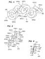
- FIG. 4is a perspective view of a coil in a free energy state in accordance with one embodiment of the invention.
- FIG. 5is a perspective view of a mandrel suitable for winding a coil, according to embodiments of the invention.
- FIG. 6is a perspective view of a mandrel, wound with a member, for use in forming a coil according to one embodiment of the invention.
- FIG. 7is a perspective view of a mandrel, wound with a member, for use in forming a coil according to another embodiment of the invention.
- FIG. 8is a side view of the coil of FIG. 4 in a deployed confined state.
- a vaso occlusive coilis a “coil of a coil.”
- the “primary configuration”refers to the member obtained when a wire is shaped into a coil, for example, as a member to be used to form an occlusive device.
- the “secondary configuration”refers to the structure obtained when the member in the primary configuration is further shaped, e.g., by winding around a mandrel.
- the “free energy state”refers to the theoretical three-dimensional configuration assumed by the member as it would exist with no outside forces on it in its secondary configuration.
- the “deployed configuration”refers to the shape after the coil has been deployed from the catheter.
- the deployed configuration of a particular devicemay differ, depending on whether the device is deployed into the open, or whether it is deployed into a body cavity which may influence the three-dimensional structures.
- the deployed configurationsgenerally comprise overlapping and intertwining loops or ovals of the strand of the secondary configuration.
- the loops or ovalscan form a closed structure such as an “O” shape (e.g., circle, oval, etc.) or can be open such as a “C” or “U” shape.
- FIG. 1illustrates a member 100 for forming a vaso-occlusive coil.
- the member 100comprises a length of wire 102 formed into the primary configuration of a helical microcoil.
- the wire 102may be any material suitable for forming a vaso-occlusive device including platinum, rhodium, palladium, tungsten, gold, silver, nitinol, and various alloys of these materials.
- the coilis made from platinum or a platinum-tungsten alloy.
- the member 100is comprised of a series of helices 104 ( a ), 104 ( b ), 104 ( c ), 104 ( d ), 104 ( e ) each having a diameter that is typically 0.125 mm to 0.625 mm.
- the member 100is formed by winding the wire 102 under tension onto a cylindrical mandrel. Once formed, the length of the member 100 may range from 5 mm to 1000 mm depending on the application.
- the amount of tension applied when forming the wire 102 , the diameter of the wire 102 , the diameter of the helices, and the spacing between the helices,are all variables which determine the stiffness of the member 100 .
- the member 100may also be constructed such that any of the aforementioned variables will vary along the length of the member.
- FIG. 2illustrates a conventional helical vaso-occlusive coil 200 shown in a free energy state.
- the coil 200is formed from a member, such as that depicted in FIG. 1 .
- the coil 200is a helical wound coil having a series of loops 202 ( a ), 202 ( b ), 202 ( c ), 202 ( d ), 202 ( e ). Therefore, in this coil, the secondary configuration is geometrically shaped similar to the member from which it is formed.
- the loops 202 ( a ), 202 ( b ), 202 ( c ), 202 ( d ), 202 ( e )may be the same size and shape (as shown) or may vary in size and shape (not shown).
- the loops 202 ( a ), 202 ( b ), 202 ( c ), 202 ( d ), 202 ( e )are helices each having a diameter that is typically 2 mm to 20 mm.
- the number of loops 202 ( a ), 202 ( b ), 202 ( c ) 202 ( d ), 202 ( e )may vary depending on the desired length of the coil.
- the length of a conventional helical vaso-occlusive coiltypically ranges from 2 cm-80 cm, depending on the application for which it will be used.
- FIG. 3Aillustrates a deployed vaso-occlusive coil 300 , such as that depicted in FIG. 2 .
- the coil 300is shown in a constrained deployed configuration, meaning it is constrained by a body cavity (not shown) into which it is deployed.
- the deployed coil 300remains helical in nature and has an axial length.
- Such conventional helical coilsfail to uniformly fill the peripheral shell “outer sphere” of the aneurysm. Instead coils having this type of structure tend to maintain some degree of axial symmetry when deployed.
- FIG. 3Billustrates a deployed vaso-occlusive coil 310 in a nearly uniformly distributed shell configuration. Successively placed coils would then assume the shape of ever-decreasing diameter shells until the aneurysm is substantially filled. Packing of coils in this manner maximizes the filling density and increases the long-term stability of the mass of coils.
- FIG. 4depicts a vaso-occlusive coil 400 in a free energy state according to an embodiment of the invention.
- this coil 400is described as a complex out-of-plane helical coil.
- the vaso-occlusive coil 400is formed from a member, such as that depicted in FIG. 1 .
- the vaso-occlusive coil 400is a series of loops 402 ( a ), 402 ( b ), 402 ( c ), 402 ( d ).
- Each loop 402 ( a - d )lies along a different axis 404 ( a ), 404 ( b ), 404 ( c ), and 404 ( d ), respectively, and in a separate plane from any other loop 402 of the series.
- coil 400is formed from a series of loops, where the series has at least four successive loops 402 , each having different axis and lying in a separate plane from any other loop 402 in the series, as described above.
- Adjacent planes, in which the loops lieform an angle of at least 30 degrees and not more that 90 degrees.
- adjacent planesform an angle of between 45 and 90 degrees and more preferably, each plane is perpendicular to an immediately preceding, or immediately succeeding plane.
- the coilmay be formed from multiple series of loops, depending on the desired overall length of the coil and the application for which it is used.
- a primary membersuch as that shown in FIG. 1
- the memberis formed into the secondary configuration by heat treatment, which is well known in the art.
- the membermay be initially formed into the secondary configuration by winding or wrapping the member around a suitably sized and shaped mandrel of a refractory material and then subjecting the member to heat treatment for a specific period of time.
- the resulting secondary configurationis, therefore, made permanent in a free energy state.
- FIG. 5shows a mandrel 500 for use in the manufacture of a vaso-occlusive coil, such as that depicted in FIG. 4 .
- the mandrelis made of a refractory material and includes a series of posts 502 ( a - i ) around which a member having a primary configuration may be wound. At least four of the posts 502 ( a - d ) each have a unique central axis 504 ( a - d ).
- the posts 502 ( a - d )are arranged such that the central axis of adjacent posts, e.g., 502 ( a ) and 502 ( b ), are at an angle greater than 30 degrees and not more than 90 degrees, and preferably between 45 degrees and 90 degrees. As shown in FIG. 5 , the posts 502 ( a - d ) intersect such that the central axes of any two adjacent posts, e.g., 502 ( a ) and 502 ( b ), are perpendicular to one another.
- the mandrel 500is constructed so that a member, such as that depicted in FIG. 1 , may be wound in either a clockwise or counterclockwise direction to create the loops. Further, the loops may be created by winding each loop in the same direction, in alternating directions, or in a random selection of directions.
- each loop 402 ( a - d )is shown as having a helical form. It will be apparent that, in addition to a helical form, each loop may be formed in an alternate form, such as elliptical or oval. While FIG. 4 shows all loops 402 ( a - d ) having a similar form, any or each loop 402 ( a - d ) could take on a different form such that the series could be any combination of forms such as helical, oval or elliptical.
- the size and shape of the loops 402( a - d ) is dictated by the size and shape of the periphery of the posts of the mandrel on which a member is wound to create the coil. Therefore, the mandrel posts could be sized and shaped to accommodate any desired combination.
- the helical form of the loops 402 ( a - d )is created by rotating the member about the axis 504 ( a - d ) of the post 502 ( a - d ) on the mandrel 500 .
- Each loop 402 ( a - d )is constructed by making at least 0.5 rotations and not more than 3.5 rotations about the axis 504 ( a - d ) of the post 502 ( a - d ) on the mandrel 500 .
- each loop 402 ( a - e )is depicted as having roughly the same size, it may be desirable to have a distal most loop 402 ( e ) smaller than an immediately successive loop 402 ( d ).
- a distal loop of a coilis defined as the loop located at a distal end 408 , which is the end of the coil 400 which enters the aneurysm first while a proximal end 406 of the coil 400 is that end which is releasably attached to a push wire or other mechanism for moving the coil through a catheter and to a treatment site.
- the loops 402 ( a - e )are helices each has a diameter that is typically 2 mm-20 mm. Loops of varying forms are similarly sized.
- the length of the coil 400may vary depending on the application, preferably the length ranges from 2 cm-80 cm.
- the vaso-occlusive coil as shown in FIG. 4is a series of loops directly connected, such that the end of one loop, i.e. 402 ( a ), is immediately connected to the start of the next loop, i.e. 402 ( b ). That is, there is no distinction between where one loop 402 ( a ) ends and the next loop 402 ( b ) begins.
- a coil formed in this waythereby eliminates any linear sections in the secondary configuration.
- it is desirable to separate loopsand a member may be wound on a mandrel such that the loops are connected by a curvilinear or linear portion of the member created during the winding process.
- a mandrel 600is wound with a member, such as that shown in FIG. 1 , to create a linear connection of successive loops.
- the memberis wound creating a loop 604 around a post 602 .
- a length 608 of the memberis laid axial along the post 606 .
- This length 608connects the loop 604 created by the winding the member on post 602 to the loop 610 created by successive winding on the adjacent post 612 .
- the loops 604 and 610are connected by a linear segment represented by the length 608 of the portion the member which is laid axially along the post 606 .
- FIG. 7depicts a mandrel 700 wound with a member, such as that shown in FIG. 1 , to create a curvilinear connection of successive loops.
- a memberis wound around a post 702 creating a loop 704 .
- a length of the member 708is wrapped around the post 706 .
- the length 708is wrapped such that it extends axially along as well as partially around the periphery of the post 706 .
- This length 708connects the loop 704 created by the winding the member on post 702 to a loop 712 created by successive winding on the adjacent post 710 .
- the loops 704 , 712are connected by a curvilinear segment.
- a proximal end 406 of the vaso-occlusive coilis attached to a distal end of a guidewire or microcatheter (not shown).
- the vaso-occlusive coilmay be attached and subsequently detached in any known manner, such as by physical pushing, or by electrolytic or mechanical detachment.
- a target siteis visualized by conventional means known in the art.
- the target siteis an aneurysm 802 .
- the aneurysmis defined by a dome 804 coming off a branch of an artery 806 .
- a catheter 808is inserted in the artery 806 , by means known in the art, until it reaches the dome 804 .
- a vaso-occlusive coil 810passes through the catheter by means of a guidewire or microcatheter until the vaso-occlusive coil enters the dome 804 of the aneurysm 802 .
- the end loop (not shown) at the distal end of the vaso-occlusive coilenters the aneurysm 802 first.
- the remaining loopsare then advanced into and fill the aneurysm 802 .
- the diameter of the majority of the loopsare approximately the same size as the dome 804 , however the entire vaso-occlusive coil is larger than the dome 804 itself and therefore the coil takes on a semi-constrained deployed configuration 810 as it fills the aneurysm 802 .
- the vaso-occlusive coil of the inventionis a desirable shape for it tends to fill the interior area 812 of the dome 804 while also filling the peripheral shell of the aneurysm 802 .
- the deployed coiltakes on a more complex, but semi-uniform shape as compared with conventional helical coils.
- the constrained deployed configuration of the coilis a higher energy state than the unconstrained deployed configuration since the aneurysm 802 constrains the coil. Nonetheless, since the diameter of the loops are approximately the same size as the aneurysm dome, the amount of force required to constrain the coil within the aneurysm dome is kept to a minimum. Once placed, the coil tends to remain in place, constrained by the walls 814 of the dome 804 , and further compaction of the coil is minimized. Additional coils may be inserted into the aneurysm until the desired density of coils in the aneurysm is achieved.
Landscapes
- Health & Medical Sciences (AREA)
- Surgery (AREA)
- Life Sciences & Earth Sciences (AREA)
- Biomedical Technology (AREA)
- Medical Informatics (AREA)
- Vascular Medicine (AREA)
- Reproductive Health (AREA)
- Engineering & Computer Science (AREA)
- Veterinary Medicine (AREA)
- Heart & Thoracic Surgery (AREA)
- Nuclear Medicine, Radiotherapy & Molecular Imaging (AREA)
- Molecular Biology (AREA)
- Animal Behavior & Ethology (AREA)
- General Health & Medical Sciences (AREA)
- Public Health (AREA)
- Neurosurgery (AREA)
- Surgical Instruments (AREA)
Abstract
Description
Claims (10)
Priority Applications (6)
| Application Number | Priority Date | Filing Date | Title |
|---|---|---|---|
| US10/790,982US7485123B2 (en) | 2004-03-01 | 2004-03-01 | Complex vaso-occlusive coils |
| CA002556047ACA2556047A1 (en) | 2004-03-01 | 2005-02-02 | Complex vaso-occlusive coils |
| JP2007501788AJP2007525304A (en) | 2004-03-01 | 2005-02-02 | Compound vaso-occlusive coil |
| EP05712874AEP1725174A1 (en) | 2004-03-01 | 2005-02-02 | Complex vaso-occlusive coils |
| PCT/US2005/003592WO2005092213A1 (en) | 2004-03-01 | 2005-02-02 | Complex vaso-occlusive coils |
| US12/353,177US20090149864A1 (en) | 2004-03-01 | 2009-01-13 | Complex vaso-occlusive coils |
Applications Claiming Priority (1)
| Application Number | Priority Date | Filing Date | Title |
|---|---|---|---|
| US10/790,982US7485123B2 (en) | 2004-03-01 | 2004-03-01 | Complex vaso-occlusive coils |
Related Child Applications (1)
| Application Number | Title | Priority Date | Filing Date |
|---|---|---|---|
| US12/353,177ContinuationUS20090149864A1 (en) | 2004-03-01 | 2009-01-13 | Complex vaso-occlusive coils |
Publications (2)
| Publication Number | Publication Date |
|---|---|
| US20050192618A1 US20050192618A1 (en) | 2005-09-01 |
| US7485123B2true US7485123B2 (en) | 2009-02-03 |
Family
ID=34887557
Family Applications (2)
| Application Number | Title | Priority Date | Filing Date |
|---|---|---|---|
| US10/790,982Expired - LifetimeUS7485123B2 (en) | 2004-03-01 | 2004-03-01 | Complex vaso-occlusive coils |
| US12/353,177AbandonedUS20090149864A1 (en) | 2004-03-01 | 2009-01-13 | Complex vaso-occlusive coils |
Family Applications After (1)
| Application Number | Title | Priority Date | Filing Date |
|---|---|---|---|
| US12/353,177AbandonedUS20090149864A1 (en) | 2004-03-01 | 2009-01-13 | Complex vaso-occlusive coils |
Country Status (5)
| Country | Link |
|---|---|
| US (2) | US7485123B2 (en) |
| EP (1) | EP1725174A1 (en) |
| JP (1) | JP2007525304A (en) |
| CA (1) | CA2556047A1 (en) |
| WO (1) | WO2005092213A1 (en) |
Cited By (16)
| Publication number | Priority date | Publication date | Assignee | Title |
|---|---|---|---|---|
| US20080319527A1 (en)* | 2007-06-22 | 2008-12-25 | Lee Jeffrey A | Shaped multi-durometer filler |
| US20090149864A1 (en)* | 2004-03-01 | 2009-06-11 | Boston Scientific Scimed, Inc. | Complex vaso-occlusive coils |
| US20130103074A1 (en)* | 2007-12-11 | 2013-04-25 | Cornell University | Method and apparatus for restricting flow through an opening in the side wall of a body lumen, and/or for reinforcing a weakness in the side wall of a body lumen, while still maintaining substantially normal flow through the body lumen |
| US20150032145A1 (en)* | 2007-12-11 | 2015-01-29 | Cornell University | Method and apparatus for restricting flow through an opening in the side wall of a body lumen, and/or for reinforcing a weakness in the side wall of a body lumen, while still maintaining substantially normal flow through the body lumen |
| US8956475B2 (en) | 2007-12-11 | 2015-02-17 | Howard Riina | Method and apparatus for restricting flow through an opening in the side wall of a body lumen, and/or for reinforcing a weakness in the side wall of a body lumen, while still maintaining substantially normal flow through the body lumen |
| US20150289881A1 (en)* | 2012-06-29 | 2015-10-15 | Kaneka Corporation | Method for producing in-vivo indwelling member |
| US9358140B1 (en) | 2009-11-18 | 2016-06-07 | Aneuclose Llc | Stent with outer member to embolize an aneurysm |
| US9636118B2 (en) | 2014-02-27 | 2017-05-02 | Incumedx, Inc. | Embolic framing microcoils |
| US9681876B2 (en) | 2013-07-31 | 2017-06-20 | EMBA Medical Limited | Methods and devices for endovascular embolization |
| US9987015B2 (en) | 2014-07-25 | 2018-06-05 | Incumedx, Inc. | Covered embolic coils |
| US10010328B2 (en) | 2013-07-31 | 2018-07-03 | NeuVT Limited | Endovascular occlusion device with hemodynamically enhanced sealing and anchoring |
| US10028747B2 (en) | 2008-05-01 | 2018-07-24 | Aneuclose Llc | Coils with a series of proximally-and-distally-connected loops for occluding a cerebral aneurysm |
| US10716573B2 (en) | 2008-05-01 | 2020-07-21 | Aneuclose | Janjua aneurysm net with a resilient neck-bridging portion for occluding a cerebral aneurysm |
| US11399845B2 (en) | 2017-12-12 | 2022-08-02 | Penumbra, Inc. | Vascular cages and methods of making and using the same |
| US11399840B2 (en) | 2019-08-13 | 2022-08-02 | Covidien Lp | Implantable embolization device |
| US12016568B2 (en) | 2005-01-07 | 2024-06-25 | Stryker Corporation | Intra-aneurysm devices |
Families Citing this family (25)
| Publication number | Priority date | Publication date | Assignee | Title |
|---|---|---|---|---|
| US7029486B2 (en)* | 2000-09-26 | 2006-04-18 | Microvention, Inc. | Microcoil vaso-occlusive device with multi-axis secondary configuration |
| DE502004008712D1 (en) | 2004-09-22 | 2009-01-29 | Dendron Gmbh | MEDICAL IMPLANT |
| AU2005304459B2 (en)* | 2004-11-09 | 2011-10-13 | Stryker European Holdings I, Llc | Vaso-occlusive devices comprising complex-shape proximal portion and smaller diameter distal portion |
| US8066036B2 (en) | 2005-11-17 | 2011-11-29 | Microvention, Inc. | Three-dimensional complex coil |
| WO2008065570A1 (en)* | 2006-11-30 | 2008-06-05 | Koninklijke Philips Electronics, N.V. | Catheter with ultrasound transducer and variable focus lens used in aneurysm assessment |
| US8801747B2 (en) | 2007-03-13 | 2014-08-12 | Covidien Lp | Implant, a mandrel, and a method of forming an implant |
| WO2009003049A2 (en) | 2007-06-25 | 2008-12-31 | Micro Vention, Inc. | Self-expanding prosthesis |
| WO2009076515A1 (en)* | 2007-12-11 | 2009-06-18 | Cornell University | Method and apparatus for sealing an opening in the side wall of a body lumen |
| US9089405B1 (en)* | 2008-09-12 | 2015-07-28 | Microvention, Inc. | Three-dimensional complex coil |
| JP6157453B2 (en) | 2011-05-11 | 2017-07-05 | マイクロベンション インコーポレイテッド | Coil packing |
| US9011480B2 (en) | 2012-01-20 | 2015-04-21 | Covidien Lp | Aneurysm treatment coils |
| US9687245B2 (en) | 2012-03-23 | 2017-06-27 | Covidien Lp | Occlusive devices and methods of use |
| EP2884945A4 (en)* | 2012-08-19 | 2016-06-15 | Christopher G M Ken | Geometric coil |
| US10531979B2 (en)* | 2013-03-15 | 2020-01-14 | Fabian Hermann Urban Füglister | Tongue deformation implant |
| US9713475B2 (en) | 2014-04-18 | 2017-07-25 | Covidien Lp | Embolic medical devices |
| US10709453B2 (en) | 2014-05-19 | 2020-07-14 | Kaneka Corporation | In vivo indwelling member and method for producing same |
| US10869673B2 (en) | 2015-02-05 | 2020-12-22 | Boston Scientific Scimed, Inc. | Embolic coil with kick-in tail |
| US10307168B2 (en) | 2015-08-07 | 2019-06-04 | Terumo Corporation | Complex coil and manufacturing techniques |
| WO2017086479A1 (en)* | 2015-11-19 | 2017-05-26 | 株式会社カネカ | In vivo indwelling member, and in vivo indwelling member placement device provided with said in vivo indwelling member |
| US10842607B2 (en) | 2016-10-14 | 2020-11-24 | Microvention, Inc. | Embolic coils |
| US10905432B2 (en) | 2018-08-22 | 2021-02-02 | Covidien Lp | Aneurysm treatment coils and associated systems and methods of use |
| US10912569B2 (en) | 2018-08-22 | 2021-02-09 | Covidien Lp | Aneurysm treatment coils and associated systems and methods of use |
| JP7751566B2 (en) | 2019-09-13 | 2025-10-08 | アバンテック バスキュラー コーポレイション | Intravascular coil and method for making same |
| CN112826563B (en)* | 2021-03-02 | 2025-06-17 | 微创神通医疗科技(上海)有限公司 | Medical implant and method of manufacturing the same |
| US20230380842A1 (en)* | 2022-05-27 | 2023-11-30 | David A. Watson | Neurocoil and mandrel for making same used in intravascular treatment |
Citations (11)
| Publication number | Priority date | Publication date | Assignee | Title |
|---|---|---|---|---|
| US4994069A (en) | 1988-11-02 | 1991-02-19 | Target Therapeutics | Vaso-occlusion coil and method |
| EP0739605A1 (en) | 1995-04-28 | 1996-10-30 | Target Therapeutics | Embolic coils with offset helical and twisted helical shapes |
| US5911731A (en) | 1995-04-20 | 1999-06-15 | Target Therapeutics, Inc. | Anatomically shaped vasoocclusive devices |
| US6322576B1 (en)* | 1997-08-29 | 2001-11-27 | Target Therapeutics, Inc. | Stable coil designs |
| WO2001093937A2 (en) | 2000-06-08 | 2001-12-13 | Micrus Corporation | Three dimensional, low friction coil, and method of manufacture |
| US20020019847A1 (en) | 1995-11-09 | 2002-02-14 | Connect One | Internet message communicator with direct output to a hard copy device |
| EP1219246A2 (en) | 1997-12-05 | 2002-07-03 | Micrus Corporation | Vasoocclusive device for treatment of aneurysms |
| WO2003059176A2 (en) | 2002-01-11 | 2003-07-24 | Microvention, Inc. | Microcoil vaso-occlusive device with multi-axis secondary configuration |
| US6605101B1 (en) | 2000-09-26 | 2003-08-12 | Microvention, Inc. | Microcoil vaso-occlusive device with multi-axis secondary configuration |
| US6635069B1 (en)* | 2000-10-18 | 2003-10-21 | Scimed Life Systems, Inc. | Non-overlapping spherical three-dimensional coil |
| US7029486B2 (en)* | 2000-09-26 | 2006-04-18 | Microvention, Inc. | Microcoil vaso-occlusive device with multi-axis secondary configuration |
Family Cites Families (3)
| Publication number | Priority date | Publication date | Assignee | Title |
|---|---|---|---|---|
| US6860893B2 (en)* | 1997-08-29 | 2005-03-01 | Boston Scientific Scimed, Inc. | Stable coil designs |
| US7645292B2 (en)* | 2003-10-27 | 2010-01-12 | Boston Scientific Scimed, Inc. | Vaso-occlusive devices with in-situ stiffening elements |
| US7485123B2 (en)* | 2004-03-01 | 2009-02-03 | Boston Scientific Scimed, Inc. | Complex vaso-occlusive coils |
- 2004
- 2004-03-01USUS10/790,982patent/US7485123B2/ennot_activeExpired - Lifetime
- 2005
- 2005-02-02JPJP2007501788Apatent/JP2007525304A/enactivePending
- 2005-02-02CACA002556047Apatent/CA2556047A1/ennot_activeAbandoned
- 2005-02-02EPEP05712874Apatent/EP1725174A1/ennot_activeWithdrawn
- 2005-02-02WOPCT/US2005/003592patent/WO2005092213A1/enactiveApplication Filing
- 2009
- 2009-01-13USUS12/353,177patent/US20090149864A1/ennot_activeAbandoned
Patent Citations (12)
| Publication number | Priority date | Publication date | Assignee | Title |
|---|---|---|---|---|
| US4994069A (en) | 1988-11-02 | 1991-02-19 | Target Therapeutics | Vaso-occlusion coil and method |
| US5911731A (en) | 1995-04-20 | 1999-06-15 | Target Therapeutics, Inc. | Anatomically shaped vasoocclusive devices |
| EP0739605A1 (en) | 1995-04-28 | 1996-10-30 | Target Therapeutics | Embolic coils with offset helical and twisted helical shapes |
| US20020019847A1 (en) | 1995-11-09 | 2002-02-14 | Connect One | Internet message communicator with direct output to a hard copy device |
| US6322576B1 (en)* | 1997-08-29 | 2001-11-27 | Target Therapeutics, Inc. | Stable coil designs |
| EP1219246A2 (en) | 1997-12-05 | 2002-07-03 | Micrus Corporation | Vasoocclusive device for treatment of aneurysms |
| WO2001093937A2 (en) | 2000-06-08 | 2001-12-13 | Micrus Corporation | Three dimensional, low friction coil, and method of manufacture |
| US6605101B1 (en) | 2000-09-26 | 2003-08-12 | Microvention, Inc. | Microcoil vaso-occlusive device with multi-axis secondary configuration |
| US7029486B2 (en)* | 2000-09-26 | 2006-04-18 | Microvention, Inc. | Microcoil vaso-occlusive device with multi-axis secondary configuration |
| US6635069B1 (en)* | 2000-10-18 | 2003-10-21 | Scimed Life Systems, Inc. | Non-overlapping spherical three-dimensional coil |
| US6929654B2 (en)* | 2000-10-18 | 2005-08-16 | Scimed Life Systems, Inc. | Non-overlapping spherical three-dimensional coil |
| WO2003059176A2 (en) | 2002-01-11 | 2003-07-24 | Microvention, Inc. | Microcoil vaso-occlusive device with multi-axis secondary configuration |
Non-Patent Citations (2)
| Title |
|---|
| PCT International Search Report for PCT/US2005/003592, Applicant: Boston Scientific Scimed, Inc., Forms PCT/ISA/210 and 220, dated Jun. 9, 2005 (9 pages). |
| PCT Written Opinion of the International Search Authority for PCT/US2005/003592, Applicant: Boston Scientific Scimed, Inc., Form PCT/ISA/237, dated Jun. 9, 2005 (6 pages). |
Cited By (30)
| Publication number | Priority date | Publication date | Assignee | Title |
|---|---|---|---|---|
| US20090149864A1 (en)* | 2004-03-01 | 2009-06-11 | Boston Scientific Scimed, Inc. | Complex vaso-occlusive coils |
| US12016568B2 (en) | 2005-01-07 | 2024-06-25 | Stryker Corporation | Intra-aneurysm devices |
| US12042151B2 (en) | 2005-01-07 | 2024-07-23 | Stryker Corporation and Stryker European Operations Holdings LLC | Intra-aneurysm devices |
| US12059157B2 (en) | 2005-01-07 | 2024-08-13 | Stryker Corporation | Intra-aneurysm devices |
| US20080319527A1 (en)* | 2007-06-22 | 2008-12-25 | Lee Jeffrey A | Shaped multi-durometer filler |
| US20150216534A1 (en)* | 2007-12-11 | 2015-08-06 | Cornell University | Method and apparatus for restricting flow through an opening in the side wall of a body lumen, and/or for reinforcing a weakness in the side wall of a body lumen, while still maintaining substantially normal flow through the body lumen |
| US8968382B2 (en)* | 2007-12-11 | 2015-03-03 | Cornell University | Method and apparatus for restricting flow through an opening in the side wall |
| US9486224B2 (en)* | 2007-12-11 | 2016-11-08 | Cornell University | Method and apparatus for restricting flow through an opening in the side wall of a body lumen, and/or for reinforcing a weakness in the side wall of a body lumen, while still maintaining substantially normal flow through the body lumen |
| US8956475B2 (en) | 2007-12-11 | 2015-02-17 | Howard Riina | Method and apparatus for restricting flow through an opening in the side wall of a body lumen, and/or for reinforcing a weakness in the side wall of a body lumen, while still maintaining substantially normal flow through the body lumen |
| US20150032145A1 (en)* | 2007-12-11 | 2015-01-29 | Cornell University | Method and apparatus for restricting flow through an opening in the side wall of a body lumen, and/or for reinforcing a weakness in the side wall of a body lumen, while still maintaining substantially normal flow through the body lumen |
| US20130103074A1 (en)* | 2007-12-11 | 2013-04-25 | Cornell University | Method and apparatus for restricting flow through an opening in the side wall of a body lumen, and/or for reinforcing a weakness in the side wall of a body lumen, while still maintaining substantially normal flow through the body lumen |
| US9763665B2 (en)* | 2007-12-11 | 2017-09-19 | Cornell University | Method and apparatus for restricting flow through an opening in the side wall of a body lumen, and/or for reinforcing a weakness in the side wall of a body lumen, while still maintaining substantially normal flow through the body lumen |
| US10028747B2 (en) | 2008-05-01 | 2018-07-24 | Aneuclose Llc | Coils with a series of proximally-and-distally-connected loops for occluding a cerebral aneurysm |
| US10716573B2 (en) | 2008-05-01 | 2020-07-21 | Aneuclose | Janjua aneurysm net with a resilient neck-bridging portion for occluding a cerebral aneurysm |
| US9358140B1 (en) | 2009-11-18 | 2016-06-07 | Aneuclose Llc | Stent with outer member to embolize an aneurysm |
| US20150289881A1 (en)* | 2012-06-29 | 2015-10-15 | Kaneka Corporation | Method for producing in-vivo indwelling member |
| US9615833B2 (en)* | 2012-06-29 | 2017-04-11 | Kaneka Corporation | Method for producing in-vivo indwelling member |
| US9681876B2 (en) | 2013-07-31 | 2017-06-20 | EMBA Medical Limited | Methods and devices for endovascular embolization |
| US10010328B2 (en) | 2013-07-31 | 2018-07-03 | NeuVT Limited | Endovascular occlusion device with hemodynamically enhanced sealing and anchoring |
| US10178995B2 (en) | 2013-07-31 | 2019-01-15 | NeuVT Limited | Methods and devices for endovascular embolization |
| US9848883B2 (en) | 2013-07-31 | 2017-12-26 | EMBA Medical Limited | Methods and devices for endovascular embolization |
| US11517320B2 (en) | 2013-07-31 | 2022-12-06 | Embolic Acceleration, Llc | Endovascular occlusion device with hemodynamically enhanced sealing and anchoring |
| US9980734B2 (en) | 2014-02-27 | 2018-05-29 | Incumedx, Inc. | Embolic framing microcoils |
| US10098645B2 (en) | 2014-02-27 | 2018-10-16 | Incumedx, Inc. | Embolic framing microcoils |
| US9636118B2 (en) | 2014-02-27 | 2017-05-02 | Incumedx, Inc. | Embolic framing microcoils |
| US9987015B2 (en) | 2014-07-25 | 2018-06-05 | Incumedx, Inc. | Covered embolic coils |
| US11399845B2 (en) | 2017-12-12 | 2022-08-02 | Penumbra, Inc. | Vascular cages and methods of making and using the same |
| US11944313B2 (en) | 2019-08-13 | 2024-04-02 | Covidien Lp | Implantable embolization device |
| US11399840B2 (en) | 2019-08-13 | 2022-08-02 | Covidien Lp | Implantable embolization device |
| US12396731B2 (en) | 2019-08-13 | 2025-08-26 | Covidien Lp | Implantable embolization device |
Also Published As
| Publication number | Publication date |
|---|---|
| CA2556047A1 (en) | 2005-10-06 |
| EP1725174A1 (en) | 2006-11-29 |
| US20050192618A1 (en) | 2005-09-01 |
| JP2007525304A (en) | 2007-09-06 |
| US20090149864A1 (en) | 2009-06-11 |
| WO2005092213A1 (en) | 2005-10-06 |
Similar Documents
| Publication | Publication Date | Title |
|---|---|---|
| US7485123B2 (en) | Complex vaso-occlusive coils | |
| JP7195375B2 (en) | Embolization device and manufacturing method thereof | |
| US6860893B2 (en) | Stable coil designs | |
| EP1467663B1 (en) | Microcoil vaso-occlusive device with multi-axis secondary configuration | |
| US6322576B1 (en) | Stable coil designs | |
| EP1720462B1 (en) | Vaso-occlusive coils with non-overlapping sections | |
| EP3110343B1 (en) | Embolic framing microcoils | |
| AU2003267287A1 (en) | Microcoil vaso-occlusive device with multi-axis secondary configuration | |
| US12396731B2 (en) | Implantable embolization device | |
| EP0743866A4 (en) | Large diameter vasoocclusion coil | |
| US9089405B1 (en) | Three-dimensional complex coil | |
| JP7630022B2 (en) | Vascular occlusion device and methods of making and using same | |
| WO2003039376A1 (en) | Microcoil vaso-occlusive device with multi-axis secondary configuration | |
| AU2002236676A1 (en) | Microcoil vaso-occlusive device with multi-axis secondary configuration |
Legal Events
| Date | Code | Title | Description |
|---|---|---|---|
| AS | Assignment | Owner name:SCIMED LIFE SYSTEMS, INC., MINNESOTA Free format text:ASSIGNMENT OF ASSIGNORS INTEREST;ASSIGNOR:PORTER, STEPHEN C.;REEL/FRAME:015054/0768 Effective date:20040301 | |
| AS | Assignment | Owner name:BOSTON SCIENTIFIC SCIMED, INC., MINNESOTA Free format text:CHANGE OF NAME;ASSIGNOR:SCIMED LIFE SYSTEMS, INC.;REEL/FRAME:018505/0868 Effective date:20050101 Owner name:BOSTON SCIENTIFIC SCIMED, INC.,MINNESOTA Free format text:CHANGE OF NAME;ASSIGNOR:SCIMED LIFE SYSTEMS, INC.;REEL/FRAME:018505/0868 Effective date:20050101 | |
| FEPP | Fee payment procedure | Free format text:PAYOR NUMBER ASSIGNED (ORIGINAL EVENT CODE: ASPN); ENTITY STATUS OF PATENT OWNER: LARGE ENTITY | |
| STCF | Information on status: patent grant | Free format text:PATENTED CASE | |
| CC | Certificate of correction | ||
| FEPP | Fee payment procedure | Free format text:PAYER NUMBER DE-ASSIGNED (ORIGINAL EVENT CODE: RMPN); ENTITY STATUS OF PATENT OWNER: LARGE ENTITY Free format text:PAYOR NUMBER ASSIGNED (ORIGINAL EVENT CODE: ASPN); ENTITY STATUS OF PATENT OWNER: LARGE ENTITY | |
| AS | Assignment | Owner name:STRYKER NV OPERATIONS LIMITED, IRELAND Free format text:ASSIGNMENT OF ASSIGNORS INTEREST;ASSIGNOR:BOSTON SCIENTIFIC SCIMED, INC.;REEL/FRAME:025969/0841 Effective date:20110103 Owner name:STRYKER CORPORATION, MICHIGAN Free format text:ASSIGNMENT OF ASSIGNORS INTEREST;ASSIGNOR:BOSTON SCIENTIFIC SCIMED, INC.;REEL/FRAME:025969/0841 Effective date:20110103 | |
| FPAY | Fee payment | Year of fee payment:4 | |
| AS | Assignment | Owner name:STRYKER EUROPEAN HOLDINGS I, LLC, MICHIGAN Free format text:NUNC PRO TUNC ASSIGNMENT;ASSIGNOR:STRYKER MEDTECH LIMITED;REEL/FRAME:037153/0241 Effective date:20151013 Owner name:STRYKER MEDTECH LIMITED, MALTA Free format text:NUNC PRO TUNC ASSIGNMENT;ASSIGNOR:STRYKER NV OPERATIONS LIMITED;REEL/FRAME:037153/0034 Effective date:20151013 | |
| AS | Assignment | Owner name:STRYKER EUROPEAN HOLDINGS I, LLC, MICHIGAN Free format text:CORRECTIVE ASSIGNMENT TO CORRECT THE INCORRECT LISTED SERIAL NOS. 09/905,670 AND 07/092,079 PREVIOUSLY RECORDED AT REEL: 037153 FRAME: 0241. ASSIGNOR(S) HEREBY CONFIRMS THE NUNC PRO TUNC ASSIGNMENT EFFECTIVE DATE 9/29/2014;ASSIGNOR:STRYKER MEDTECH LIMITED;REEL/FRAME:038043/0011 Effective date:20151013 Owner name:STRYKER MEDTECH LIMITED, MALTA Free format text:CORRECTIVE ASSIGNMENT TO CORRECT THE INCORRECT SERIAL # 09/905,670 AND 07/092,079 PREVIOUSLY RECORDED AT REEL: 037153 FRAME: 0034. ASSIGNOR(S) HEREBY CONFIRMS THE NUNC PRO TUNC ASSIGNMENT;ASSIGNOR:STRYKER NV OPERATIONS LIMITED;REEL/FRAME:038039/0001 Effective date:20151013 | |
| FPAY | Fee payment | Year of fee payment:8 | |
| AS | Assignment | Owner name:STRYKER EUROPEAN OPERATIONS HOLDINGS LLC, MICHIGAN Free format text:CHANGE OF NAME;ASSIGNOR:STRYKER EUROPEAN HOLDINGS III, LLC;REEL/FRAME:052860/0716 Effective date:20190226 Owner name:STRYKER EUROPEAN HOLDINGS III, LLC, DELAWARE Free format text:NUNC PRO TUNC ASSIGNMENT;ASSIGNOR:STRYKER EUROPEAN HOLDINGS I, LLC;REEL/FRAME:052861/0001 Effective date:20200519 | |
| MAFP | Maintenance fee payment | Free format text:PAYMENT OF MAINTENANCE FEE, 12TH YEAR, LARGE ENTITY (ORIGINAL EVENT CODE: M1553); ENTITY STATUS OF PATENT OWNER: LARGE ENTITY Year of fee payment:12 | |
| AS | Assignment | Owner name:STRYKER CORPORATION, MICHIGAN Free format text:CHANGE OF ADDRESS;ASSIGNOR:STRYKER CORPORATION;REEL/FRAME:069737/0184 Effective date:20241217 Owner name:STRYKER EUROPEAN OPERATIONS HOLDINGS LLC, MICHIGAN Free format text:CHANGE OF ADDRESS;ASSIGNOR:STRYKER EUROPEAN OPERATIONS HOLDINGS LLC;REEL/FRAME:069730/0754 Effective date:20241217 |