US7484925B2 - Rotary axial fan assembly - Google Patents
Rotary axial fan assemblyDownload PDFInfo
- Publication number
- US7484925B2 US7484925B2US11/125,557US12555705AUS7484925B2US 7484925 B2US7484925 B2US 7484925B2US 12555705 AUS12555705 AUS 12555705AUS 7484925 B2US7484925 B2US 7484925B2
- Authority
- US
- United States
- Prior art keywords
- fan
- primary
- fan blades
- hub
- stator
- Prior art date
- Legal status (The legal status is an assumption and is not a legal conclusion. Google has not performed a legal analysis and makes no representation as to the accuracy of the status listed.)
- Expired - Fee Related, expires
Links
Images


Classifications
- F—MECHANICAL ENGINEERING; LIGHTING; HEATING; WEAPONS; BLASTING
- F04—POSITIVE - DISPLACEMENT MACHINES FOR LIQUIDS; PUMPS FOR LIQUIDS OR ELASTIC FLUIDS
- F04D—NON-POSITIVE-DISPLACEMENT PUMPS
- F04D29/00—Details, component parts, or accessories
- F04D29/26—Rotors specially for elastic fluids
- F04D29/32—Rotors specially for elastic fluids for axial flow pumps
- F04D29/325—Rotors specially for elastic fluids for axial flow pumps for axial flow fans
- F04D29/326—Rotors specially for elastic fluids for axial flow pumps for axial flow fans comprising a rotating shroud
- F—MECHANICAL ENGINEERING; LIGHTING; HEATING; WEAPONS; BLASTING
- F04—POSITIVE - DISPLACEMENT MACHINES FOR LIQUIDS; PUMPS FOR LIQUIDS OR ELASTIC FLUIDS
- F04D—NON-POSITIVE-DISPLACEMENT PUMPS
- F04D29/00—Details, component parts, or accessories
- F04D29/26—Rotors specially for elastic fluids
- F04D29/32—Rotors specially for elastic fluids for axial flow pumps
- F04D29/38—Blades
- F04D29/384—Blades characterised by form
- F—MECHANICAL ENGINEERING; LIGHTING; HEATING; WEAPONS; BLASTING
- F04—POSITIVE - DISPLACEMENT MACHINES FOR LIQUIDS; PUMPS FOR LIQUIDS OR ELASTIC FLUIDS
- F04D—NON-POSITIVE-DISPLACEMENT PUMPS
- F04D29/00—Details, component parts, or accessories
- F04D29/40—Casings; Connections of working fluid
- F04D29/52—Casings; Connections of working fluid for axial pumps
- F04D29/54—Fluid-guiding means, e.g. diffusers
- F04D29/541—Specially adapted for elastic fluid pumps
- F04D29/542—Bladed diffusers
- F04D29/544—Blade shapes
- F—MECHANICAL ENGINEERING; LIGHTING; HEATING; WEAPONS; BLASTING
- F04—POSITIVE - DISPLACEMENT MACHINES FOR LIQUIDS; PUMPS FOR LIQUIDS OR ELASTIC FLUIDS
- F04D—NON-POSITIVE-DISPLACEMENT PUMPS
- F04D29/00—Details, component parts, or accessories
- F04D29/66—Combating cavitation, whirls, noise, vibration or the like; Balancing
- F04D29/661—Combating cavitation, whirls, noise, vibration or the like; Balancing especially adapted for elastic fluid pumps
- F—MECHANICAL ENGINEERING; LIGHTING; HEATING; WEAPONS; BLASTING
- F01—MACHINES OR ENGINES IN GENERAL; ENGINE PLANTS IN GENERAL; STEAM ENGINES
- F01P—COOLING OF MACHINES OR ENGINES IN GENERAL; COOLING OF INTERNAL-COMBUSTION ENGINES
- F01P5/00—Pumping cooling-air or liquid coolants
- F01P5/02—Pumping cooling-air; Arrangements of cooling-air pumps, e.g. fans or blowers
- F01P5/06—Guiding or ducting air to, or from, ducted fans
Definitions
- the inventionrelates to cooling systems, more particularly to a fan assembly utilized for moving air through a heat exchanger.
- Heat exchangersto dissipate heat collected in the operation of the motor vehicle to the ambient air.
- These heat exchangersinclude radiators for cooling an internal combustion engine or a heater core for providing heat to a passenger compartment for climate control.
- Internal combustion engine cooling systems that utilize a heat exchangermay also include a rotary axial fan for enhancing the movement of air through the heat exchanger.
- a radiator in conventional motor vehiclesincludes a fan rearward of the radiator for forcing air through the radiator.
- a shroudis provided to generally restrict the air to flow axially through the radiator and the fan.
- the fanmay be driven directly from the operation of the internal combustion engine by a belt or the like.
- the fanmay be driven by a motor for rotating the fan and forcing the air through the exchanger, as commonly utilized for transversely mounted internal combustion engines. Air is commonly forced through a conventional heater core through a fan which is operated by the climate controls within the passenger compartment.
- Fan assembliesoften include a rotary axial fan that is supported by a hub on the shroud.
- the hubis supported by an array of stator fan blades extending inward from the shroud for structurally supporting the rotary axial fan and for permitting air to pass through the shroud.
- Stator fan bladestypically increase an associated sound level of the fan assembly.
- a motormay be mounted to the hub and supported by the stator fan blades of the shroud, for imparting rotation to the rotary axial fan. Heat generated can be convected from the motor by air passing through the shroud.
- a goal of the present inventionis to improve the performance and efficiency of rotary axial fans for moving air through a heat exchanger for an internal combustion engine cooling system to thereby conserve energy; reduce costs in operation of the associated motor vehicle; and improve the compactness of the internal combustion engine cooling system.
- An aspect of the present inventionis to provide a rotary axial fan for moving air through a heat exchanger for an internal combustion engine cooling system.
- the fanincludes a hub extending annularly about a central axis of rotation.
- the hubis mounted to and rotated by a drive member.
- a plurality of elongate spaced apart primary fan bladeseach have a base attached to the hub and extend radially outward from the hub.
- An annular shroudis attached to the plurality of primary fan blades and is supported coaxially with the central axis.
- the annular shroudhas a generally circumferential wall portion spaced radially from the hub to limit radial flow of air along the primary fan blades.
- a plurality of secondary fan bladesare interposed between the primary fan blades and each have a first end attached to the annular shroud and a blade section projecting from the shroud. Each secondary fan blade terminates in a second end that is not attached to the hub.
- a further aspect of the present inventionis to provide a rotary axial fan for moving air through a heat exchanger for an internal combustion engine cooling system, including a hub extending annularly about a central axis of rotation, which is mounted to and rotated by a drive member.
- a plurality of elongate spaced apart primary fan bladeseach have a base attached to the hub and radially extend outward.
- a first annular shroudis attached to the plurality of primary fan blades and is supported coaxially with the central axis.
- the first annular shroudhas a generally circumferential wall portion spaced radially from the hub to limit the radial flow of air along the primary fan blades.
- a second annular shroudis attached to the plurality of primary fan blades and is supported coaxially with the central axis as well.
- the second annular shroudhas a generally circumferential wall portion spaced radially outward from the first annular shroud to limit the radial flow of air along the primary fan blades.
- a plurality of secondary fan bladesare interposed between the primary fan blades. Each secondary fan blade has a first end attached to one of the first and second annular shrouds and a blade section projecting therefrom and terminating a second end that is not attached to the hub.
- the stator fanincludes a shroud that is adapted to be mounted proximate to a heat exchanger for conveying a flow of fluid through the heat exchanger and the shroud.
- An array of stator fan bladesextend inward from the shroud and support a hub oriented generally centrally within the shroud.
- the hubis adapted to receive a rotary axial fan.
- Each stator fan bladehas a generally uniform thickness oriented generally perpendicular to a direction of fluid flow.
- Each stator fan bladeis generally linear and is oriented offset from a radial direction relative to the hub. The thickness and orientation of the stator fan blades enhance the efficiency of fluid flow and thereby provide a reduced sound output from the rotary axial fan assembly.
- FIG. 1is a schematic illustration of an internal combustion engine cooling system in accordance with the teachings of the present invention
- FIG. 2is a front perspective view of a first rotary axial fan embodiment in accordance with the teachings of the present invention
- FIG. 3is a front perspective view of another rotary axial fan embodiment in accordance with the teachings of the present invention.
- FIG. 4is a front perspective view of a preferred rotary axial fan embodiment in accordance with the teachings of the present invention.
- FIG. 5is a side partial section view of an alternative embodiment rotary axial fan in accordance with the teachings of the present invention.
- FIG. 6is a partially exploded front perspective view of the rotary axial fan of FIG. 5 ;
- FIG. 7is a front elevation view of another alternative embodiment rotary axial fan in accordance with the teachings of the present invention.
- FIG. 8is a side partial section view of the rotary axial fan of FIG. 7 ;
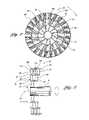
- FIG. 9is a perspective view of a rotary axial fan assembly in accordance with the present invention.
- FIG. 10is an axial end view of a stator fan of the rotary axial fan assembly of FIG. 9 ;
- FIG. 11is a perspective view of the stator fan of the rotary axial fan assembly of FIG. 9 .
- an internal combustion engine cooling systemis illustrated schematically and indicated generally by reference numeral 10 .
- the systemincludes a radiator indicated by reference numeral 12 that receives heated coolant from the internal combustion engine (not shown) and transfers heat from the coolant to air that passes therethrough. Air is passed through the radiator by movement of the vehicle and air is forced by a rotary axial fan 14 .
- an external shroud 16is provided to limit the moving of air to travel in an axial direction.
- the shroud 16is mounted to the radiator 12 .
- the fan 14is mounted to a drive member 18 , which is driven by a motor 20 .
- the motor 20drives the drive member 18 and fan 14 for forcing air through the radiator 12 , shroud 16 and fan 14 thereby cooling coolant that is passed through the radiator 12 .
- the drive member 18can be driven directly by the internal combustion engine by a belt drive system, a gear drive system or the like.
- the internal combustion engine cooling system 10may include any heat exchanger, such as a heater core, which passes coolant therethrough and air is forced by a fan 14 for passing air into the passenger compartment of a vehicle.
- the rotary axial fan 14is illustrated in greater detail in cooperation with the shroud 16 , which is illustrated in phantom.
- the fan 14includes a hub 22 , which extends annularly about a central axis 24 of the fan 14 .
- the hub 22includes a mounting surface 26 for enabling the hub 22 to be attached to and rotated by the drive member 18 .
- the fan 14is driven in the clockwise direction as indicated by an arcuate arrow in FIG. 2 for forcing air through the fan 14 in the flow direction indicated by the linear arrow in FIG. 2 .
- the fanmay be driven in a counterclockwise direction opposite the arcuate arrow for forcing air through the fan 14 in a reverse flow direction than that indicated by the linear arrow.
- the fan 14includes a plurality of elongate spaced apart primary fan blades 28 . Specifically, eight primary fan blades 28 are illustrated in the fan 14 of FIG. 2 . However, any number of primary fan blades is contemplated by the present invention and the quantity is dictated by the requirements of a specific cooling system application.
- Each of the primary fan blades 28has a base 30 attached to the hub 22 .
- Each primary fan blade 28extends radially outward from the hub 22 and is pitched at an angle such that rotation in the clockwise direction forces the air through the fan 14 .
- the primary fan blades 28terminate in a free tip 32 proximate to an internal cavity of the external shroud 16 , with a tip clearance of, for example, 0.05 inches.
- the fan 14includes an annular shroud 34 that is attached to and supported by the plurality of primary fan blades 28 .
- the annular shroud 34is generally coaxial with the central axis 24 .
- the annular shroud 34has a generally circumferential wall portion that is spaced radially from the hub 22 .
- the annular shroud 34separates each primary fan blade 28 into a first primary fan blade segment 36 and a second primary blades segment 38 .
- the first primary blade segment 36includes the primary fan blade base 30 .
- the second primary blade segment 38includes the free tip 32 .
- the annular shroud 34also enhances the structural rigidity of the fan 14 .
- the annular shroud 34interconnects each primary fan blade 28 and reduces the cantilevered portion of each free tip 32 .
- the fan 14can be formed unitarily from a manufacturing process such as plastic injection molding.
- the rotary axial fan 14also includes a plurality of secondary fan blades 40 . Specifically, eight secondary fan blades 40 are illustrated, each interposed between a sequential pair of primary fan blades 28 .
- Each secondary fan blade 40has a base 42 attached to the annular shroud 34 , and a blade section projecting externally from the annular shroud 34 and terminating in a free tip 44 that is cantilevered from the annular shroud 34 .
- the secondary fan blades 40each have a radial length less than the radial length of the primary fan blades 28 .
- the primary fan blades 28 and the secondary fan blades 40collectively terminate in an outboard radial region with a clearance of, for example, 0.05 inches from the internal cavity of the external shroud 16 .
- the secondary fan blades 40are illustrated having a uniform pitch with the second primary blade segment 38 . However, any pitch is contemplated within the spirit and scope of the present invention.
- Conventional rotary axial fansinclude primary fan blades that diverge outwardly thereby causing a decrease in fan blade solidity at the radially outward regions of the fan blades.
- the secondary fan blades 40increase blade solidity with increasing radius of the rotary axial fan 14 , and fill in the unused space provided between a sequential pair of primary fan blades 28 .
- the secondary fan blades 40can be formed unitarily with the rotary axial fan 14 through a manufacturing process such as plastic injection molding.
- the rotary axial fan 14has primary and secondary fan blades 28 , 40 resulting in an increased output pressure for a given speed. Flow rate is increased as well due to the tight configuration of fan blades. Further, efficiency is improved by the addition of the secondary fan blades 40 . The overall structural integrity of the primary fan blades 28 and secondary fan blades 40 is enhanced due to the annular shroud 34 .
- any number of primary fan blades 28 and secondary fan blades 40is contemplated by the present invention.
- the number of fan blades, the separation of fan blades, and the output pressures and flow ratesare dictated by the requirements of a specific application that requires a rotary axial fan. Due to the benefits provided by the rotary axial fan 14 , less power is required to operate the fan 14 , and a greater output pressure and flow rate are provided. Accordingly, the rotary axial fan 14 of the present invention satisfies the criteria of an internal combustion engine cooling system with a fan that is smaller or more compact than a conventional rotary axial fan that would provide the same output results. Accordingly, the fan 14 of the present invention provides a more compact and efficient cooling system.
- each primary fan blade 28is comprised of a first primary blade segment 50 and a second primary blade segment 52 , wherein the radial length of the first primary blade segment 50 is substantially greater than that of the second primary blade segment 52 .
- the fan 46also includes a series of secondary fan blades 54 which extend radially outward from the annular shroud 48 . Due to the outward spacing of the annular shroud 48 , in comparison to the prior embodiment, recirculation at the free tips 32 of the primary fan blades 28 is reduced due to the shortened length of the second primary blade segment 52 . However, the solidity of the fan 46 is less than that of the prior embodiment because the secondary fan blades 54 occupy less of the separation region than the prior embodiment. Both embodiments add blockage by the addition of the annular shrouds 34 , 48 , however the output results are enhanced due to the addition of the secondary fan blades 40 , 54 .
- the fan 56includes a hub 22 and a series of primary fan blades 28 .
- the fan 56includes an annular shroud 58 that is attached to the radial outward ends of the primary fan blades 28 . Therefore, the annular shroud 58 provides the outmost radial extent of the fan 56 and is sized for clearance of, for example, 0.05 inches within the corresponding internal cavity of the external shroud 16 .
- the fan 56includes a series of secondary fan blades 60 , each interposed between a sequential pair of primary fan blades 28 .
- the secondary fan blades 60are mounted to and extend inwardly from the annular shroud 58 .
- the secondary fan blades 60are sized to increase the solidity of the fan 56 .
- the secondary fan blades 60are sized such that the secondary fan blades 60 do not converge to the hub 22 , which would result in flow blockage around the hub 22 and therefore are sized in radial length such that performance of the fan 56 is maximized.
- the fan 56maximizes performance and efficiency.
- the fan 62includes a first array of primary fan blades 64 and a second array of primary fan blades 66 .
- Each array 64 , 66is arranged about the hub 22 in an axially stacked manner.
- the second array of primary fan blades 66is rotationally offset from the first array of primary fan blades 64 . This offset is one half the angular dimension between a sequential pair of primary fan blades in the first array 64 .
- the fan 62includes an annular shroud 68 attached to and supported by the terminal ends of the primary fan blades 28 .
- the annular shroud 68interconnects the first and second arrays of primary fan blades 64 , 66 and minimizes recirculation at the terminating ends of the primary fan blades 28 .
- the fan 62includes a series of secondary fan blades 70 extending inwardly from the annular shroud 68 .
- the secondary fan blades 70are in stacked coaxial alignment with the first and second arrays of primary fan blades 64 , 66 .
- the secondary fan blades 70are spaced apart from each array 64 , 66 and are oriented therebetween.
- the rotary axial fan 62is illustrated exploded with a first fan portion 72 and a second fan portion 74 .
- the first fan portion 72is molded integrally with a hub portion 76 , the first array of primary fan blades 64 , a first shroud portion 78 and half of the series of secondary fan blades 70 .
- the second fan portion 74is molded integrally and includes a second hub portion 80 , the second array of primary fan blades 66 , a second shroud portion 82 and half of the plurality of secondary fan blades 70 .
- the stacked axial fan blades 64 , 70 , 66provide twice the output pressure in comparison with the conventional design at the same operating speed and flow rate.
- the fan 62may require more manufacturing processes and components than the conventional rotary axial fan, the stacked axial fan 62 provides more output in a reduced and compact fan size. Additionally, the output results and efficiency are improved by reduced recirculation provided by the annular shroud 68 and increased solidity that is maximized with the stacked primary fan blades 64 , 66 and the interposed secondary fan blades 70 .
- FIGS. 7 and 8another alternative embodiment rotary axial fan 84 is illustrated for moving air through a heat exchanger in an internal combustion engine cooling system.
- the fan 84includes a hub 22 , which is driven by a drive member 18 for rotation of the fan 84 in a clockwise direction.
- the fan 84includes a series of primary fan blade segments 86 extending outward in a radial direction.
- a first annular shroud 88is attached to and oriented about the plurality of first primary fan blade segments 86 .
- a plurality of second primary fan blade segments 90extend radially outward from the first annular shroud 88 .
- the quantity of second primary fan blade segments 90is equal to that of the first primary fan blade segments 86 and each second primary fan blade segment 90 is aligned with a corresponding first primary fan blade segment 86 . Additionally, a series of first secondary fan blade segments 92 are each provided interposed between a sequential pair of second primary fan blade segments 90 and are attached to and extending outwardly from the first annular shroud 88 .
- a second annular shroud 94is provided attached to the outward end of each second primary fan blade segment 90 and each outward end of each first secondary fan blade segment 92 .
- the second annular shroud 94reduces recirculation at the outward radial ends of the second primary fan blade segments 90 and the first secondary fan blade segments 92 and provides structural rigidity by interconnecting these fan blade segments 90 , 92 .
- the second primary fan blade segments 90 and the first secondary fan blade segments 92are arranged in a first array 96 and a second array 98 .
- the first and second arrays 96 , 98are stacked axially, both of which are connected to the first annular shroud 88 and the second annular shroud 94 . Additionally, the second array 98 is rotationally offset from the first array 96 .
- a series of third primary fan blade segments 100extend radially outward from the second annular shroud 94 .
- a second secondary fan blade segment 102is interposed between each sequential pair of third primary fan blade segments 100 , and is aligned with the corresponding first secondary fan blade segment 92 .
- a third annular shroud 106is provided attached to the outward radial terminal end of the third primary fan blade segments 100 and the second secondary fan blade segments 102 .
- a tertiary fan blade 108is provided between each sequential pair of third primary fan blade segments 100 and second secondary fan blades segments 102 .
- the third primary fan blade segments 100 , the second secondary fan blade segments 102 and the tertiary fan blade 108are provided in a first array 110 , a second array 112 and a third array 114 .
- These three arrays 110 , 112 , 114are stacked axially and are each attached to the second annular shroud 94 and the third annular shroud 106 . Additionally, each of these arrays 110 , 112 , 114 are rotationally offset.
- the rotary axial fan 84 illustrated in FIGS. 7 and 8illustrates that any number of annular shrouds, any number of secondary and subsequent fan blades, and any number of arrays of fan blades is contemplated within the present invention and is prescribed by the requirements of the specific heat exchanger in an internal combustion engine cooling system.
- the annular shroudsreduce recirculation and increase efficiency.
- the secondary and subsequent fan bladesenhance performance and increase efficiency.
- the stacked arraysincrease performance as well. Accordingly, the rotary axial fan of the present invention satisfies the cooling requirements of a given system with enhanced performance and efficiency and reduced size in comparison to the prior art.
- the fan assembly 116includes a rotary axial fan 118 and a stator fan 120 .
- the stator fan 120is fixed within the vehicle and supports the rotary axial fan 118 .
- the stator fan 120includes a shroud 122 , which is generally annular for limiting a direction of air flow through the assembly 116 to a generally axial direction.
- the shroud 122includes a plurality of mounting flanges 124 for mounting the assembly 116 proximate to a heat exchanger such as a radiator.
- the stator fan 120includes a radial array of stator fan blades 126 converging centrally inward to a hub 128 , and each lying in a plane generally parallel to an axial flow direction L.
- the hub 128is supported by the stator fan blades 126 .
- the rotary axial fan 118is mounted to the hub 128 for rotation relative thereto.
- the rotary axial fan 118includes a series of rotary fan blades 130 extending from a rotary hub 132 .
- the rotary fan blades 130are inclined relative to the axial flow direction at an attack angle ⁇ , which is angled (non-radial) relative to the hub 132 such that rotation of the rotary axial fan 118 in a counterclockwise direction, as illustrated by the arcuate arrow R in FIG. 9 , causes a flow of air in a generally axial direction through the shroud 122 , as illustrated by the linear (axial) directional arrow L in FIG. 9 .
- the fan assembly 116is illustrated as a puller fan assembly, wherein air is pulled through the radiator and subsequently through the fan assembly 116
- the inventioncontemplates that the rotary axial fan 118 may be rotated in a clockwise direction such that air is forced in a reverse linear direction relative to the arrow L depicted in FIG. 9 for pushing air through the fan assembly 116 and subsequently through the associated radiator.
- Such rotationmay be controlled by electronics or may be a function of the relationship of the rotary axial fan blades 130 relative to the hub 132 .
- the rotary axial fan 118may be detachable from the stator fan 120 for being mounted in either a pusher or puller orientation.
- stator fan 120reduces an output sound level in comparison to prior art stator fans due to the characteristics of the stator fan blades 126 which optimize the interaction of flowing air with the blades 126 .
- stator fan designmay be developed for a particular application, and subsequently prototyped and tested to provide a stator fan blade arrangement that minimizes output sound level of the stator fan 120 .
- Heat transfer factorsmay be considered in to these processes for maximizing cooling.
- the fan assembly 116 illustrated in FIG. 9is sized to adequately cool a radiator of a predetermined diesel engine.
- other types of engines, engine cooling systems, and cooling of other heat exchangersis contemplated by the present invention.
- the rotary fan blade 118is rotationally driven by a motor 134 that is mounted to the stator fan hub 128 .
- the rotary axial fan 118is rotated relative to the stator fan 120 .
- the motor 134 illustrated in FIG. 9may be, for example, a brushless DC motor having a fitting 136 for receiving and ducting wiring to the motor 134 .
- a motor casing 138may be provided for utilization as a heat sink for conducting heat from the motor 134 into the flow of air via a radial array of heat fins 140 extending radially outward from the motor casing 138 , each lying in a plane generally parallel to the axial flow direction L.
- the motor casing 138may be formed from a thermally conductive material for facilitating this heat transfer; for example, the motor casing 138 may be formed from aluminum, and may be die cast.
- the motor casing 138may include a motor stator encapsulated therein for imparting the rotation to an associated motor rotor mounted upon an output shaft to which the rotary axial fan 118 is mounted.
- the fan motor statormay be encapsulated within a thermally conductive polymer and pressed into the motor casing 138 for heat transfer from the stator through the conductive polymer to the motor casing 138 and subsequently to the fins 140 , thereby increasing the efficiency of heat transfer and consequently cooling of the motor 134 .
- stator fan blades 126In order to optimize both heat transfer and sound reduction of the stator fan blades 126 , an exemplary arrangement of stator fan blades 126 is illustrated in FIGS. 9-11 .
- the stator fan blades 126each extend from the hub 128 at an angle that is offset from a radial direction relative to the hub 128 . This offset from a radial direction is indicated in FIG. 10 by ⁇ .
- the offset angle ⁇may be approximately seventy-five degrees.
- the direction of the offsetmay be opposed to a radial rotation of the rotary axial fan 118 .
- Linear stator fan blades 126facilitate optimal sound reduction, however, non-linear stator fan blades are contemplated within the spirit and scope of the present invention.
- stator fan blades 126are oriented so that a width (in axial flow direction) of the fan blades 126 is oriented in a generally axial direction of the stator fan 120 and a thickness, referenced by label t, of the stator fan blades 126 is oriented generally perpendicular to the plane of the fan blade 126 .
- an optimal number of stator fan blades 126 and an optimal width and thickness of the stator fan blades 126may be determined for structural integrity, noise reduction, and heat transfer for a predetermined cooling application.
- eleven stator fan blades 126are utilized.
- Each stator fan bladehas a width that is substantially greater than the thickness for convection of air along the axial surfaces thereof. Accordingly, each stator fan blade 126 is provided with a thickness t within a range of four to five millimeters.
- the motor 134includes an axially end cap 142 .
- the end cap 142 and the motor casing 138are illustrated fastened directly to an array of mounting bosses 144 displaced about the stator hub 128 .
- heat from the motor 134is also directly conducted to the stator fan hub 128 .
- the stator fan 120may be formed from a thermally conductive material for dissipating heat from the motor 134 to the stator fan blades 126 , for subsequently cooling from the flow of air therethrough.
- the stator fan 120 illustrated in FIGS. 9-11may be die cast from aluminum for diesel and industrial applications.
- the inventioncontemplates that the stator fan 120 may be formed integrally, from separate components, and from various component materials.
- the inventioncontemplates that the stator fan 120 may be formed from other materials, such as from thermally conductive polymers which may be manufactured from an injection molded process.
Landscapes
- Engineering & Computer Science (AREA)
- Mechanical Engineering (AREA)
- General Engineering & Computer Science (AREA)
- Physics & Mathematics (AREA)
- Geometry (AREA)
- Structures Of Non-Positive Displacement Pumps (AREA)
Abstract
Description
Claims (28)
Priority Applications (2)
| Application Number | Priority Date | Filing Date | Title |
|---|---|---|---|
| US11/125,557US7484925B2 (en) | 2005-05-10 | 2005-05-10 | Rotary axial fan assembly |
| PCT/US2006/017134WO2006137990A2 (en) | 2005-05-10 | 2006-05-03 | Rotary axial fan assembly |
Applications Claiming Priority (1)
| Application Number | Priority Date | Filing Date | Title |
|---|---|---|---|
| US11/125,557US7484925B2 (en) | 2005-05-10 | 2005-05-10 | Rotary axial fan assembly |
Publications (2)
| Publication Number | Publication Date |
|---|---|
| US20060257251A1 US20060257251A1 (en) | 2006-11-16 |
| US7484925B2true US7484925B2 (en) | 2009-02-03 |
Family
ID=37419271
Family Applications (1)
| Application Number | Title | Priority Date | Filing Date |
|---|---|---|---|
| US11/125,557Expired - Fee RelatedUS7484925B2 (en) | 2005-05-10 | 2005-05-10 | Rotary axial fan assembly |
Country Status (2)
| Country | Link |
|---|---|
| US (1) | US7484925B2 (en) |
| WO (1) | WO2006137990A2 (en) |
Cited By (30)
| Publication number | Priority date | Publication date | Assignee | Title |
|---|---|---|---|---|
| US20080159867A1 (en)* | 2007-01-02 | 2008-07-03 | Sheng-An Yang | Impeller assembly |
| US20100068060A1 (en)* | 2006-12-11 | 2010-03-18 | Hidetake Ota | Cooling fan |
| US20100134971A1 (en)* | 2008-11-28 | 2010-06-03 | Hong Fu Jin Precision Industry (Shenzhen) Co., Ltd. | Heat dissipation apparatus |
| US20100290900A1 (en)* | 2009-05-17 | 2010-11-18 | Wayne Krouse | Hydropower system with increased power input characteristics |
| US20110114286A1 (en)* | 2008-12-05 | 2011-05-19 | Mitsubishi Heavy Industries, Ltd. | Vehicle heat-exchange module and vehicle having the same |
| US20110200429A1 (en)* | 2010-02-15 | 2011-08-18 | Nidec Servo Corporation | Impeller and blower fan including the same |
| US20120049523A1 (en)* | 2009-04-29 | 2012-03-01 | Bersiek Shamel A | Wind jet turbine ii |
| US20120108161A1 (en)* | 2010-10-27 | 2012-05-03 | Lg Electronics Inc. | Air conditioner with outdoor unit |
| US8192141B1 (en)* | 2007-04-05 | 2012-06-05 | The United States Of America As Represented By The Secretary Of The Air Force | Dual compression rotor |
| US20120244008A1 (en)* | 2011-03-25 | 2012-09-27 | Shun-Chen Chang | Impeller structure |
| US20130045120A1 (en)* | 2011-08-18 | 2013-02-21 | General Electric Company | Segmented fan assembly |
| US20130170995A1 (en)* | 2012-01-04 | 2013-07-04 | Ming-Ju Chen | Axial flow fan blade structure and axial flow fan thereof |
| US20130209242A1 (en)* | 2010-08-05 | 2013-08-15 | Mitsuba Corporation | Cooling fan |
| US20160208823A1 (en)* | 2015-01-19 | 2016-07-21 | Hamilton Sundstrand Corporation | Shrouded fan rotor |
| US20170029091A1 (en)* | 2015-07-27 | 2017-02-02 | Northrop Grumman Systems Corporation | Propeller having extending outer blade |
| US20170257007A1 (en)* | 2014-09-08 | 2017-09-07 | Siemens Aktiengesellschaft | Generator for a power plant |
| US20170284405A1 (en)* | 2016-04-04 | 2017-10-05 | Windmill Ceiling Fans LLC | Ceiling fan and method of manufacture |
| US20180171966A1 (en)* | 2015-06-18 | 2018-06-21 | New World Energy Enterprises Limited | Wind turbine with rotating augmentor |
| US10066597B2 (en)* | 2016-12-14 | 2018-09-04 | Thunderbird Power Corp | Multiple-blade wind machine with shrouded rotors |
| US20190055958A1 (en)* | 2017-08-17 | 2019-02-21 | Lenovo (Beijing) Co., Ltd. | Electronic device and cooling fan |
| US10465693B2 (en)* | 2016-12-21 | 2019-11-05 | Quorum International, Inc. | Windmill ceiling fan |
| US10660235B2 (en)* | 2018-10-17 | 2020-05-19 | Arris Enterprises Llc | Fan with pivotable blades, and corresponding electronics cooling system and methods |
| DE102019101277A1 (en) | 2019-01-18 | 2020-07-23 | Hanon Systems | Axial fan assembly for vehicles |
| US10773817B1 (en) | 2018-03-08 | 2020-09-15 | Northrop Grumman Systems Corporation | Bi-directional flow ram air system for an aircraft |
| WO2020188593A1 (en)* | 2019-03-21 | 2020-09-24 | Tvs Motor Company Limited | A cooling system for a power unit |
| US11048309B2 (en) | 2018-07-02 | 2021-06-29 | Acer Incorporated | Heat dissipation module |
| EP3312427B1 (en) | 2016-10-19 | 2022-08-17 | ebm-papst Mulfingen GmbH & Co. KG | Ventilator with ventilator wheel and guide wheel |
| US20240286757A1 (en)* | 2023-02-23 | 2024-08-29 | ESS 2 Tech, LLC | Fluid accelerator |
| US12319395B1 (en)* | 2022-12-19 | 2025-06-03 | Submersed Technologies Pp2 Ab | Propulsion device for exerting thrust to a fluid |
| US12415615B2 (en) | 2023-02-23 | 2025-09-16 | ESS 2 Tech, LLC | Fluid accelerator |
Families Citing this family (22)
| Publication number | Priority date | Publication date | Assignee | Title |
|---|---|---|---|---|
| US7324339B2 (en)* | 2005-12-21 | 2008-01-29 | International Business Machines Corporation | Dual impeller push-pull axial fan heat sink |
| WO2009152420A2 (en)* | 2008-06-13 | 2009-12-17 | The Penn State Research Foundation | Dipole flow driven resonators for fan noise mitigation |
| US8267673B1 (en) | 2011-05-04 | 2012-09-18 | John Pairaktaridis | Brushless cooling fan |
| TWI504809B (en) | 2012-04-20 | 2015-10-21 | Delta Electronics Inc | Axial fan |
| FR2989999B1 (en)* | 2012-04-26 | 2016-01-01 | Sdmo Ind | COOLING DEVICE COMPRISING AN AXIAL FAN WITH CENTRAL FLOW RECTIFICATION AND CORRESPONDING ELECTROGEN GROUP. |
| DE102012109542A1 (en)* | 2012-10-08 | 2014-04-10 | Ebm-Papst Mulfingen Gmbh & Co. Kg | "Flow straightener for an axial fan" |
| KR101490957B1 (en)* | 2013-12-18 | 2015-02-06 | 현대자동차 주식회사 | Control system of flowing air into vehicle engine room and method for the same |
| US20150338109A1 (en)* | 2014-05-20 | 2015-11-26 | Carrier Corporation | Auxiliary heating assembly for use with residential air handlers |
| CN204213047U (en)* | 2014-10-24 | 2015-03-18 | 常州格力博有限公司 | Axial-flow blower fan blade |
| US10375901B2 (en)* | 2014-12-09 | 2019-08-13 | Mtd Products Inc | Blower/vacuum |
| JP6451387B2 (en)* | 2015-02-17 | 2019-01-16 | 株式会社デンソー | Blower for vehicle |
| WO2017015708A1 (en)* | 2015-07-24 | 2017-02-02 | Tooleytech Pty Ltd | Fan assembly |
| EP3156749A1 (en)* | 2015-10-13 | 2017-04-19 | Liebherr-Hausgeräte Lienz GmbH | Refrigeration and/or freezer device |
| DE102017114034A1 (en)* | 2017-06-23 | 2018-12-27 | Oliver Schmitz | Heat storage element for decentralized room ventilation systems with axial fan, heat storage arrangement and decentralized room ventilation system |
| DE102018204061A1 (en)* | 2018-03-16 | 2019-09-19 | Mahle International Gmbh | Radial fan for conveying air |
| CN111043057B (en)* | 2018-10-15 | 2022-03-25 | 广东美的白色家电技术创新中心有限公司 | Counter-rotating fan |
| US10687440B1 (en)* | 2019-01-24 | 2020-06-16 | Dell Products L.P. | Multi-radial-zone varying blade density fan system |
| KR102026048B1 (en)* | 2019-01-28 | 2019-09-26 | 최석봉 | Portable fan for clean zone formation using air curtain |
| CN110757716B (en)* | 2019-11-21 | 2024-10-22 | 贵州华烽电器有限公司 | Manufacturing method of fan guide cover |
| KR102335566B1 (en)* | 2020-06-26 | 2021-12-07 | 주식회사 씨엔스카이텍 | High-power generation vortex windmill device of integrated rotating body |
| US12381441B2 (en)* | 2021-02-25 | 2025-08-05 | Regal Beloit America, Inc. | Electric machine assembly having end frame cooling |
| US20220333611A1 (en)* | 2021-04-14 | 2022-10-20 | Stokes Technology Development Ltd. | Counter-rotating axial air moving device |
Citations (24)
| Publication number | Priority date | Publication date | Assignee | Title |
|---|---|---|---|---|
| US1986151A (en)* | 1933-08-05 | 1935-01-01 | Internat Engineering Inc | Fan |
| US2154313A (en) | 1938-04-01 | 1939-04-11 | Gen Electric | Directing vane |
| US4265596A (en) | 1977-11-22 | 1981-05-05 | Kabushiki Kaisha Toyota Chuo Kenkyusho | Axial flow fan with auxiliary blades |
| US4358245A (en) | 1980-09-18 | 1982-11-09 | Bolt Beranek And Newman Inc. | Low noise fan |
| US4482302A (en)* | 1981-01-09 | 1984-11-13 | Etudes Techniques Et Representations Industrielles E.T.R.I. | Axial electric fan of the flat type |
| US4548548A (en) | 1984-05-23 | 1985-10-22 | Airflow Research And Manufacturing Corp. | Fan and housing |
| US4664593A (en) | 1983-04-08 | 1987-05-12 | Aisin Seiki Kabushiki Kaisha | Blade configuration for shrouded motor-driven fan |
| US5445215A (en) | 1992-12-22 | 1995-08-29 | Herbert; Edward | Fan assembly with heat sink |
| US5454695A (en)* | 1994-07-05 | 1995-10-03 | Ford Motor Company | High output engine cooling fan |
| US5460485A (en) | 1993-03-29 | 1995-10-24 | Nippondenso Co., Ltd. | Blower with an improved shroud assembly |
| US6024537A (en) | 1997-07-29 | 2000-02-15 | Valeo Engine Cooling, Inc. | Axial flow fan |
| US6139265A (en) | 1996-05-01 | 2000-10-31 | Valeo Thermique Moteur | Stator fan |
| US6142733A (en) | 1998-12-30 | 2000-11-07 | Valeo Thermique Moteur | Stator for fan |
| US6174232B1 (en)* | 1999-09-07 | 2001-01-16 | International Business Machines Corporation | Helically conforming axial fan check valve |
| US6350104B1 (en) | 1998-07-28 | 2002-02-26 | Valeo Thermique Moteur | Fan blade |
| US20020094275A1 (en) | 2001-01-12 | 2002-07-18 | Emerson Electric Co. | Split blade radial fan |
| US20020182071A1 (en) | 2001-05-29 | 2002-12-05 | Belady Christian L. | Enhanced performance fan with the use of winglets |
| US6514052B2 (en) | 2001-03-30 | 2003-02-04 | Emerson Electric Co. | Two sided radial fan for motor cooling |
| US20030059297A1 (en) | 2001-09-27 | 2003-03-27 | Stagg Jonathan B. | Dynamically sealing ring fan shroud assembly |
| US20030123988A1 (en) | 2001-12-31 | 2003-07-03 | Jason Wen | Fan blades |
| US6599085B2 (en)* | 2001-08-31 | 2003-07-29 | Siemens Automotive, Inc. | Low tone axial fan structure |
| US6648602B2 (en) | 2001-12-27 | 2003-11-18 | Sunonwealth Electric Machine Industry Co., Ltd. | Fan having balancing blade sets |
| US20050081542A1 (en) | 2003-10-16 | 2005-04-21 | Daimlerchrysler Ag | Method for actuating a fan using a plurality of characteristic curves and a control program for controlling the power of the fan |
| US6951443B1 (en)* | 2000-09-08 | 2005-10-04 | General Electric Company | Wind turbine ring/shroud drive system |
- 2005
- 2005-05-10USUS11/125,557patent/US7484925B2/ennot_activeExpired - Fee Related
- 2006
- 2006-05-03WOPCT/US2006/017134patent/WO2006137990A2/enactiveApplication Filing
Patent Citations (25)
| Publication number | Priority date | Publication date | Assignee | Title |
|---|---|---|---|---|
| US1986151A (en)* | 1933-08-05 | 1935-01-01 | Internat Engineering Inc | Fan |
| US2154313A (en) | 1938-04-01 | 1939-04-11 | Gen Electric | Directing vane |
| US4265596A (en) | 1977-11-22 | 1981-05-05 | Kabushiki Kaisha Toyota Chuo Kenkyusho | Axial flow fan with auxiliary blades |
| US4358245A (en) | 1980-09-18 | 1982-11-09 | Bolt Beranek And Newman Inc. | Low noise fan |
| US4482302A (en)* | 1981-01-09 | 1984-11-13 | Etudes Techniques Et Representations Industrielles E.T.R.I. | Axial electric fan of the flat type |
| US4664593A (en) | 1983-04-08 | 1987-05-12 | Aisin Seiki Kabushiki Kaisha | Blade configuration for shrouded motor-driven fan |
| US4548548A (en) | 1984-05-23 | 1985-10-22 | Airflow Research And Manufacturing Corp. | Fan and housing |
| US5445215A (en) | 1992-12-22 | 1995-08-29 | Herbert; Edward | Fan assembly with heat sink |
| US5460485A (en) | 1993-03-29 | 1995-10-24 | Nippondenso Co., Ltd. | Blower with an improved shroud assembly |
| US5454695A (en)* | 1994-07-05 | 1995-10-03 | Ford Motor Company | High output engine cooling fan |
| US6139265A (en) | 1996-05-01 | 2000-10-31 | Valeo Thermique Moteur | Stator fan |
| US6024537A (en) | 1997-07-29 | 2000-02-15 | Valeo Engine Cooling, Inc. | Axial flow fan |
| US6350104B1 (en) | 1998-07-28 | 2002-02-26 | Valeo Thermique Moteur | Fan blade |
| US6142733A (en) | 1998-12-30 | 2000-11-07 | Valeo Thermique Moteur | Stator for fan |
| US6174232B1 (en)* | 1999-09-07 | 2001-01-16 | International Business Machines Corporation | Helically conforming axial fan check valve |
| US6951443B1 (en)* | 2000-09-08 | 2005-10-04 | General Electric Company | Wind turbine ring/shroud drive system |
| US20020094275A1 (en) | 2001-01-12 | 2002-07-18 | Emerson Electric Co. | Split blade radial fan |
| US6435828B1 (en) | 2001-01-12 | 2002-08-20 | Emerson Electric Co. | Split blade radial fan |
| US6514052B2 (en) | 2001-03-30 | 2003-02-04 | Emerson Electric Co. | Two sided radial fan for motor cooling |
| US20020182071A1 (en) | 2001-05-29 | 2002-12-05 | Belady Christian L. | Enhanced performance fan with the use of winglets |
| US6599085B2 (en)* | 2001-08-31 | 2003-07-29 | Siemens Automotive, Inc. | Low tone axial fan structure |
| US20030059297A1 (en) | 2001-09-27 | 2003-03-27 | Stagg Jonathan B. | Dynamically sealing ring fan shroud assembly |
| US6648602B2 (en) | 2001-12-27 | 2003-11-18 | Sunonwealth Electric Machine Industry Co., Ltd. | Fan having balancing blade sets |
| US20030123988A1 (en) | 2001-12-31 | 2003-07-03 | Jason Wen | Fan blades |
| US20050081542A1 (en) | 2003-10-16 | 2005-04-21 | Daimlerchrysler Ag | Method for actuating a fan using a plurality of characteristic curves and a control program for controlling the power of the fan |
Non-Patent Citations (1)
| Title |
|---|
| International Search Report for corresponding PCT Application No. PCT/US06/17134, mailed Jun. 18, 2008, 11 pages. |
Cited By (40)
| Publication number | Priority date | Publication date | Assignee | Title |
|---|---|---|---|---|
| US20100068060A1 (en)* | 2006-12-11 | 2010-03-18 | Hidetake Ota | Cooling fan |
| US8342808B2 (en)* | 2006-12-11 | 2013-01-01 | Mitsuba Corporation | Cooling fan |
| US20080159867A1 (en)* | 2007-01-02 | 2008-07-03 | Sheng-An Yang | Impeller assembly |
| US8356469B1 (en) | 2007-04-05 | 2013-01-22 | The United States Of America As Represented By The Secretary Of The Air Force | Gas turbine engine with dual compression rotor |
| US8192141B1 (en)* | 2007-04-05 | 2012-06-05 | The United States Of America As Represented By The Secretary Of The Air Force | Dual compression rotor |
| US8072757B2 (en)* | 2008-11-28 | 2011-12-06 | Hong Fu Jin Precision Industry (Shenzhen) Co. Ltd. | Heat dissipation apparatus |
| US20100134971A1 (en)* | 2008-11-28 | 2010-06-03 | Hong Fu Jin Precision Industry (Shenzhen) Co., Ltd. | Heat dissipation apparatus |
| US8573343B2 (en)* | 2008-12-05 | 2013-11-05 | Mitsubishi Heavy Industries, Ltd. | Vehicle heat-exchange module and vehicle having the same |
| US20110114286A1 (en)* | 2008-12-05 | 2011-05-19 | Mitsubishi Heavy Industries, Ltd. | Vehicle heat-exchange module and vehicle having the same |
| US20120049523A1 (en)* | 2009-04-29 | 2012-03-01 | Bersiek Shamel A | Wind jet turbine ii |
| US20100290900A1 (en)* | 2009-05-17 | 2010-11-18 | Wayne Krouse | Hydropower system with increased power input characteristics |
| US20110200429A1 (en)* | 2010-02-15 | 2011-08-18 | Nidec Servo Corporation | Impeller and blower fan including the same |
| US8753086B2 (en)* | 2010-02-15 | 2014-06-17 | Nidec Servo Corporation | Blower fan |
| US20130209242A1 (en)* | 2010-08-05 | 2013-08-15 | Mitsuba Corporation | Cooling fan |
| US9803645B2 (en)* | 2010-08-05 | 2017-10-31 | Mitsuba Corporation | Cooling fan |
| US9228591B2 (en)* | 2010-10-27 | 2016-01-05 | Lg Electronics Inc. | Air conditioner with outdoor unit |
| US20120108161A1 (en)* | 2010-10-27 | 2012-05-03 | Lg Electronics Inc. | Air conditioner with outdoor unit |
| US20120244008A1 (en)* | 2011-03-25 | 2012-09-27 | Shun-Chen Chang | Impeller structure |
| US20130045120A1 (en)* | 2011-08-18 | 2013-02-21 | General Electric Company | Segmented fan assembly |
| US8998588B2 (en)* | 2011-08-18 | 2015-04-07 | General Electric Company | Segmented fan assembly |
| US20130170995A1 (en)* | 2012-01-04 | 2013-07-04 | Ming-Ju Chen | Axial flow fan blade structure and axial flow fan thereof |
| US20170257007A1 (en)* | 2014-09-08 | 2017-09-07 | Siemens Aktiengesellschaft | Generator for a power plant |
| US20160208823A1 (en)* | 2015-01-19 | 2016-07-21 | Hamilton Sundstrand Corporation | Shrouded fan rotor |
| US20180171966A1 (en)* | 2015-06-18 | 2018-06-21 | New World Energy Enterprises Limited | Wind turbine with rotating augmentor |
| US20170029091A1 (en)* | 2015-07-27 | 2017-02-02 | Northrop Grumman Systems Corporation | Propeller having extending outer blade |
| US20170284405A1 (en)* | 2016-04-04 | 2017-10-05 | Windmill Ceiling Fans LLC | Ceiling fan and method of manufacture |
| EP3312427B1 (en) | 2016-10-19 | 2022-08-17 | ebm-papst Mulfingen GmbH & Co. KG | Ventilator with ventilator wheel and guide wheel |
| US10066597B2 (en)* | 2016-12-14 | 2018-09-04 | Thunderbird Power Corp | Multiple-blade wind machine with shrouded rotors |
| US10465693B2 (en)* | 2016-12-21 | 2019-11-05 | Quorum International, Inc. | Windmill ceiling fan |
| US11566632B2 (en)* | 2017-08-17 | 2023-01-31 | Lenovo (Beijing) Co., Ltd. | Electronic device and cooling fan |
| US20190055958A1 (en)* | 2017-08-17 | 2019-02-21 | Lenovo (Beijing) Co., Ltd. | Electronic device and cooling fan |
| US10773817B1 (en) | 2018-03-08 | 2020-09-15 | Northrop Grumman Systems Corporation | Bi-directional flow ram air system for an aircraft |
| US11048309B2 (en) | 2018-07-02 | 2021-06-29 | Acer Incorporated | Heat dissipation module |
| US10660235B2 (en)* | 2018-10-17 | 2020-05-19 | Arris Enterprises Llc | Fan with pivotable blades, and corresponding electronics cooling system and methods |
| DE102019101277A1 (en) | 2019-01-18 | 2020-07-23 | Hanon Systems | Axial fan assembly for vehicles |
| WO2020188593A1 (en)* | 2019-03-21 | 2020-09-24 | Tvs Motor Company Limited | A cooling system for a power unit |
| US12319395B1 (en)* | 2022-12-19 | 2025-06-03 | Submersed Technologies Pp2 Ab | Propulsion device for exerting thrust to a fluid |
| US20240286757A1 (en)* | 2023-02-23 | 2024-08-29 | ESS 2 Tech, LLC | Fluid accelerator |
| US12409945B2 (en)* | 2023-02-23 | 2025-09-09 | ESS 2 Tech, LLC | Fluid accelerator |
| US12415615B2 (en) | 2023-02-23 | 2025-09-16 | ESS 2 Tech, LLC | Fluid accelerator |
Also Published As
| Publication number | Publication date |
|---|---|
| US20060257251A1 (en) | 2006-11-16 |
| WO2006137990A3 (en) | 2009-04-16 |
| WO2006137990A2 (en) | 2006-12-28 |
Similar Documents
| Publication | Publication Date | Title |
|---|---|---|
| US7484925B2 (en) | Rotary axial fan assembly | |
| JP4697492B2 (en) | Electric turbocharger | |
| KR101019832B1 (en) | Centrifugal blower | |
| US9948158B2 (en) | Motor cooling systems and devices | |
| US6909210B1 (en) | Cooling system for dynamoelectric machine | |
| US20070237656A1 (en) | Rotary fan with encapsulated motor assembly | |
| JP5259416B2 (en) | Series axial fan | |
| US7381027B2 (en) | Fan motor | |
| US6817831B2 (en) | Engine-cooling fan assembly with overlapping fans | |
| US20110123370A1 (en) | Electric water pump | |
| US5765630A (en) | Radiator with air flow directing fins | |
| JP2010196478A (en) | Cooling structure of electric-motor assisted supercharger | |
| JP2011513619A (en) | Fan shroud with modular vane set | |
| US8459216B2 (en) | Air distribution scroll with volute assembly | |
| US20220170469A1 (en) | Counter-Rotating Fan Assembly | |
| US6428277B1 (en) | High speed, low torque axial flow fan | |
| US10982914B2 (en) | Engine cooling assembly | |
| EP4198318A1 (en) | Electric fan | |
| GB2422003A (en) | Combined fan and heat exchanger | |
| KR102082260B1 (en) | Assembly of fan and shroud | |
| CN119137379A (en) | Device for conducting cooling air at a motor receptacle for a fan motor | |
| US20070128038A1 (en) | Engine cooling fan with ring reinforcement | |
| JPH06272555A (en) | Power source cooling device |
Legal Events
| Date | Code | Title | Description |
|---|---|---|---|
| AS | Assignment | Owner name:ENGINEERED MACHINED PRODUCTS, INC., MICHIGAN Free format text:ASSIGNMENT OF ASSIGNORS INTEREST;ASSIGNORS:CARLSON, JEREMY S.;PIPKORN, NICHOLAS T.;STEPHENS, TODD R.;REEL/FRAME:016190/0139;SIGNING DATES FROM 20050512 TO 20050517 | |
| AS | Assignment | Owner name:EMP ADVANCED DEVELOPMENT, LLC, MICHIGAN Free format text:ASSIGNMENT OF ASSIGNORS INTEREST;ASSIGNOR:ENGINEERED MACHINED PRODUCTS, INC.;REEL/FRAME:017373/0720 Effective date:20060317 | |
| AS | Assignment | Owner name:PRUDENTIAL CAPITAL PARTNERS, L.P., AS COLLATERAL A Free format text:SECURITY AGREEMENT;ASSIGNOR:EMP ADVANCED DEVELOPMENT, LLC;REEL/FRAME:019640/0790 Effective date:20070615 | |
| AS | Assignment | Owner name:GENERAL ELECTRIC CAPITAL CORPORATION, CONNECTICUT Free format text:SECURITY AGREEMENT;ASSIGNOR:EMP ADVANCED DEVELOPMENT, LLC;REEL/FRAME:019699/0847 Effective date:20070615 | |
| AS | Assignment | Owner name:ABLECO FINANCE LLC, AS COLLATERAL AGENT, NEW YORK Free format text:GRANT OF A SECURITY INTEREST;ASSIGNOR:EMP ADVANCED DEVELOPMENT, LLC;REEL/FRAME:021976/0719 Effective date:20071220 | |
| STCF | Information on status: patent grant | Free format text:PATENTED CASE | |
| CC | Certificate of correction | ||
| FEPP | Fee payment procedure | Free format text:PAT HOLDER CLAIMS SMALL ENTITY STATUS, ENTITY STATUS SET TO SMALL (ORIGINAL EVENT CODE: LTOS); ENTITY STATUS OF PATENT OWNER: SMALL ENTITY | |
| AS | Assignment | Owner name:ABLECO FINANCE LLC, AS COLLATERAL AGENT, NEW YORK Free format text:GRANT OF A SECURITY INTEREST - PATENTS;ASSIGNOR:ENGINEERED MACHINE PRODUCTS, INC.;REEL/FRAME:028132/0124 Effective date:20120427 | |
| FPAY | Fee payment | Year of fee payment:4 | |
| AS | Assignment | Owner name:EMP ADVANCED DEVELOPMENT, LLC, MICHIGAN Free format text:RELEASE BY SECURED PARTY;ASSIGNOR:PRUDENTIAL CAPITAL PARTNERS, L.P.;REEL/FRAME:030643/0388 Effective date:20130614 | |
| FPAY | Fee payment | Year of fee payment:8 | |
| AS | Assignment | Owner name:PNC BANK, NATIONAL ASSOCIATION, PENNSYLVANIA Free format text:SECURITY INTEREST;ASSIGNORS:ENGINEERED MACHINED PRODUCTS, INC.;EMP ADVANCED DEVELOPMENT, LLC;REEL/FRAME:050824/0397 Effective date:20191023 | |
| AS | Assignment | Owner name:ENGINEERED MACHINED PRODUCTS, INC., MICHIGAN Free format text:RELEASE BY SECURED PARTY;ASSIGNOR:ABELCO FINANCE LLC;REEL/FRAME:050849/0049 Effective date:20191023 Owner name:EMP ADVANCED DEVELOPMENT, LLC, MICHIGAN Free format text:RELEASE BY SECURED PARTY;ASSIGNOR:ABELCO FINANCE LLC;REEL/FRAME:050849/0080 Effective date:20191023 | |
| FEPP | Fee payment procedure | Free format text:MAINTENANCE FEE REMINDER MAILED (ORIGINAL EVENT CODE: REM.); ENTITY STATUS OF PATENT OWNER: SMALL ENTITY | |
| LAPS | Lapse for failure to pay maintenance fees | Free format text:PATENT EXPIRED FOR FAILURE TO PAY MAINTENANCE FEES (ORIGINAL EVENT CODE: EXP.); ENTITY STATUS OF PATENT OWNER: SMALL ENTITY | |
| STCH | Information on status: patent discontinuation | Free format text:PATENT EXPIRED DUE TO NONPAYMENT OF MAINTENANCE FEES UNDER 37 CFR 1.362 | |
| FP | Lapsed due to failure to pay maintenance fee | Effective date:20210203 | |
| AS | Assignment | Owner name:EMP ADVANCED DEVELOPMENT, LLC, MICHIGAN Free format text:RELEASE BY SECURED PARTY;ASSIGNOR:PNC BANK, NATIONAL ASSOCIATION;REEL/FRAME:058306/0107 Effective date:20211029 Owner name:ENGINEERED MACHINED PRODUCTS, INC., MICHIGAN Free format text:RELEASE BY SECURED PARTY;ASSIGNOR:PNC BANK, NATIONAL ASSOCIATION;REEL/FRAME:058306/0107 Effective date:20211029 |