US7483824B1 - Self-checking test generator for partially-modeled processors by propagating fuzzy states - Google Patents
Self-checking test generator for partially-modeled processors by propagating fuzzy statesDownload PDFInfo
- Publication number
- US7483824B1 US7483824B1US11/308,039US30803906AUS7483824B1US 7483824 B1US7483824 B1US 7483824B1US 30803906 AUS30803906 AUS 30803906AUS 7483824 B1US7483824 B1US 7483824B1
- Authority
- US
- United States
- Prior art keywords
- model
- self
- instruction
- unknown
- state
- Prior art date
- Legal status (The legal status is an assumption and is not a legal conclusion. Google has not performed a legal analysis and makes no representation as to the accuracy of the status listed.)
- Expired - Fee Related, expires
Links
- 238000012360testing methodMethods0.000titleclaimsabstractdescription175
- 230000001902propagating effectEffects0.000titleclaimsdescription6
- 238000013461designMethods0.000claimsdescription26
- 239000013598vectorSubstances0.000claimsdescription18
- 238000000034methodMethods0.000claimsdescription13
- 230000000644propagated effectEffects0.000claimsdescription5
- 230000004044responseEffects0.000claimsdescription4
- 230000007547defectEffects0.000claimsdescription3
- 230000008569processEffects0.000claimsdescription3
- 238000004590computer programMethods0.000claims4
- 238000004519manufacturing processMethods0.000claims1
- 230000006870functionEffects0.000description10
- 229910052710siliconInorganic materials0.000description9
- 239000010703siliconSubstances0.000description9
- 230000006399behaviorEffects0.000description6
- 238000010586diagramMethods0.000description6
- XUIMIQQOPSSXEZ-UHFFFAOYSA-NSiliconChemical compound[Si]XUIMIQQOPSSXEZ-UHFFFAOYSA-N0.000description5
- 230000008859changeEffects0.000description3
- 238000012545processingMethods0.000description3
- 230000008901benefitEffects0.000description2
- 238000012986modificationMethods0.000description2
- 230000004048modificationEffects0.000description2
- JBRZTFJDHDCESZ-UHFFFAOYSA-NAsGaChemical compound[As]#[Ga]JBRZTFJDHDCESZ-UHFFFAOYSA-N0.000description1
- 229910001218Gallium arsenideInorganic materials0.000description1
- 230000003542behavioural effectEffects0.000description1
- 239000000835fiberSubstances0.000description1
- 230000002068genetic effectEffects0.000description1
- 230000006872improvementEffects0.000description1
- 239000000463materialSubstances0.000description1
- 230000003287optical effectEffects0.000description1
- 230000000717retained effectEffects0.000description1
- 239000000523sampleSubstances0.000description1
- 239000004065semiconductorSubstances0.000description1
Images


Classifications
- G—PHYSICS
- G01—MEASURING; TESTING
- G01R—MEASURING ELECTRIC VARIABLES; MEASURING MAGNETIC VARIABLES
- G01R31/00—Arrangements for testing electric properties; Arrangements for locating electric faults; Arrangements for electrical testing characterised by what is being tested not provided for elsewhere
- G01R31/28—Testing of electronic circuits, e.g. by signal tracer
- G01R31/317—Testing of digital circuits
- G01R31/3181—Functional testing
- G01R31/3183—Generation of test inputs, e.g. test vectors, patterns or sequences
- G01R31/318342—Generation of test inputs, e.g. test vectors, patterns or sequences by preliminary fault modelling, e.g. analysis, simulation
- G01R31/318357—Simulation
Definitions
- This inventionrelates to test systems, and more particularly to generating self-checking tests using fuzzy behavioral models.
- test programsthat provide adequate coverage of gates and transistors within the chip can be challenging. Most transistors within the chip do not connect directly to the limited number of external input-output I/O leads or “pins”. Creation of the test program may begin long before the first prototypes are manufactured.
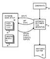
- FIG. 1illustrates testing before and after first prototypes are available.
- test patternswere manually generated by the chip designer or test engineer who wrote stimuli (input values) and obtained expected outputs from a logic simulator.
- Test vectors that have both inputs and expected outputswere then loaded onto to automated tester 14 , which applied physical signals to device-under-test 16 , and compared outputs generated by device-under-test 16 to the expected outputs. Any mismatches were reported to the test operator and caused the chip to fail.
- a probe card that contacts I/O pads on device-under-test 16 on a wafercould be connected to automated tester 14 , or a packaged chip could be used as device-under-test 16 .
- a probe card that contacts I/O pads on device-under-test 16 on a wafercould be connected to automated tester 14 , or a packaged chip could be used as device-under-test 16 .
- hundreds of thousands of dollars or moreare often required to produce the first prototypes of device-under-test 16 . It is often desirable to begin testing before the first prototypes are available.
- Testbench 18is a simulator that receives the inputs from the test program, and generates outputs that can be compared to the expected outputs from the test program.
- Testbench 18could be a hardware-based simulator such as a chassis filled with boards of programmable-logic chips that can be programmed with the logic that is eventually formed on the IC chip, device-under-test 16 .
- Testbench 18could also be a software-based simulator that executes on a computer.
- Quickturnfrom Cadence
- VCSfrom Synopsys
- NC Verilogfrom Cadence
- testbench 18may be updated, allowing the test engineer to adjust the test vectors to test the updated design.
- the test vectorsmay be adjusted to improve coverage of the chip's logic, and additional test vectors may be created before first silicon.
- test vectorsmay be created using automated tools.
- a random-number generatormay create a series of input values for some of the inputs, such as values for a bus input.
- Self-checking test generatorsare one type of test-generation tool that also generate expected outputs. The input values are applied to a model of the device to be tested. The model predicts the expected outputs based on the input values and a current state of the model.
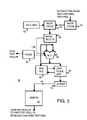
- FIGS. 2A-Eshow self-checking test generation for a simple device.
- adder 10generates an output that is the sum of two multi-bit inputs and a single-bit carry-in CIN. For example, when the multi-bit input values of 5 and 3 are applied and CIN is 0, the expected output of adder 10 is 8.
- Adder 10could eventually be a block on a post-silicon device-under-test chip, but initially could be a model of the device to be tested.
- a self-checking test generatoruses the model of the device block to generate test inputs and expected outputs.
- a self-checking test programgenerates random values to apply to the multi-bit inputs of adder 10 , such as by calling a random-number function RND(A) or RND(B).
- the self-checking test generatoraccesses a model of adder 10 that predicts the expected output of adder 10 , given the applied inputs. For example, the model of adder 10 predicts that the expected output is the sum of the two multi-bit inputs and the carry-in, or RND(A)+RND(B)+CIN.
- the model for adder 10could be called by the self-checking test-generating program, or could be written directly into the self-checking test program as shown in the simplified pseudo-code of FIG. 2C .
- FIG. 2Cnested loops are used to generate a series of seed values A, B for the random number functions.
- the carry-inis set to 0.
- the expected output for adder 10is the sum of the random multi-bit values generated from seed values A, B, and the carry-in CIN.
- FIG. 2Da common problem with self-checking test generator programs is shown.
- Self-checking test generatorsneed to predict results of the generated test vectors. To predict results the self-checking test generators must model the device under test. Creating an exact software model of the design under test (DUT) is often a difficult undertaking. For complex designs with short schedules it is not practical to create an exact model. For these reasons it is practical to model the important design behaviors and leave the less important features un-modeled.
- FIG. 2Dis an example where CIN from unmodeled logic 20 is not modeled by the self-checking test generator while adder 10 is modeled.
- the expected output of adder 10is the sum of the three inputs to adder 10 , and one of the three inputs, CIN, is unknown because of unmodeled logic 20 , the expected output of adder 20 is not able to be generated by the self-checking test generator program. This is a problem that must be solved for self-checking to be useful. Solving this problem is not as simple as ignoring the unknown output of this one adder. In most complex designs unknown outputs will propagate to many other parts of the design. It is possible to ignore all states that unknown logic may propagate to, but this may result in ignoring most of the design. Furthermore, this ignores many operations that are modeled that could have been checked if the inputs were known.
- test generatorcould be set to generate only positive-number inputs.
- Constraining test generation to avoid a specific caseis undesirable. While such constraints may solve the complex modeling problem, some logic may not be fully tested. This solution leaves a coverage hole where some of the design is not tested. These intentional coverage holes are dangerous because bugs may reside in the logic that is untested. To solve this coverage-hole problem, test engineers may create additional tests to ensure no area goes untested. This is undesirable additional work.
- What is desiredis a self-checking test generator program for use with unmodeled logic.
- a self-checking test generator programthat handles unknown states from unmodeled logic is desirable.
- a more automated self-checking test generator programthat does not require the test engineer to constrain test generation to produce known states is desirable.
- FIG. 1illustrates testing before and after first prototypes are available.
- FIGS. 2A-Eshow self-checking test generation for a simple device.
- FIG. 3is a diagram highlighting a test program executing on a processor core block.
- FIG. 4is a high-level diagram of a self-checking test generator program that uses fuzzy logic models for generating expected outputs.
- FIG. 5shows propagation of unknown logic states through fuzzy models.
- FIGS. 6A-Cshow an example of fuzzy models used by a self-checking test generator program.
- FIG. 7is a flowchart of operation of a self-checking test generator that uses fuzzy models.
- FIG. 8is a mid-level block diagram of a self-checking test generator program using a software DUT model to generate a self-checking test program.
- the present inventionrelates to an improvement in self-checking test generator programs.
- the following descriptionis presented to enable one of ordinary skill in the art to make and use the invention as provided in the context of a particular application and its requirements.
- Various modifications to the preferred embodimentwill be apparent to those with skill in the art, and the general principles defined herein may be applied to other embodiments. Therefore, the present invention is not intended to be limited to the particular embodiments shown and described, but is to be accorded the widest scope consistent with the principles and novel features herein disclosed.
- fuzzy models that explicitly handle unknown statesmay be used with self-checking test generator programs.
- unmodeled logicare used to generate unknown states before the logic is modeled.
- Models for logic blocks that have already been designed and modeledare updated to allow for inputs in the unknown states. Unknown inputs may propagate to the outputs of these modeled logic blocks, allowing unknowns generated by unmodeled logic to propagate through modeled blocks.
- a self-checking test generator programmay automatically generate test vectors with expected outputs by using fuzzy models for blocks in the device to be tested. Unknown states that are propagated to chip outputs may be ignored during actual testing of a device.
- FIG. 3is a diagram highlighting a test program executing on a processor core block.
- CPU 80may be one of many blocks in a system chip that may also have caches, various controllers, and other blocks. Test programs created by a self-checking test generator program may also be used to test these other blocks (not shown).
- Program counter 82contains part of an instruction's address and is typically advanced by the instruction length for each sequential instruction fetched. Program counter 82 is loaded with a branch address when program branching occurs. The instruction address is generated from program counter 82 and the instruction is fetched by instruction fetcher 88 and decoded by instruction decoder 92 .
- test inputs from a test program created by a self-checking test generator programare loaded into instruction cache 83 .
- These test inputs loaded into instruction cache 83are instructions that can be decoded and executed by CPU 80 .
- These instructions from the test programare then fetched by instruction fetcher 88 in a sequence determined by sequentially advancing program counter 82 or by loading branch target addresses into program counter 82 when branches are taken.
- Arithmetic-logic-unit ALU 94reads operands from register file 96 , performs an operation indicated by the decoded instruction, and writes the result either back to register file 96 , or to memory through load-store unit 98 .
- Load-store address 86 generated by load-store unit 98causes the results of the test program being executed by CPU 80 to be written to memory 81 . For example, data results of the test program may be written to a block within memory 81 .
- the test results stored into memory 81may be scanned out by specialized test logic, or may be written to a dummy external memory that is really an external tester.
- the external testermay compare the test results read from memory 81 with expected test results to determine when a test failure has occurred, such as when some logic in CPU 80 has a physical fault.
- the expected test resultsmay be generated by the self-checking test generator program that generated the test-program instructions that were loaded into instruction cache 83 .
- Another way to detect chip failuresis to examine flags 84 and/or the contents of register file 96 that are generated by CPU 80 during test-program instruction execution.
- an overflow flag generated by ALU 94could signal a physical defect when the self-checking test generator program does not cause an overflow.
- ALU 94could compare values generated earlier in the test program being executed on CPU 80 , and flags 84 could be set on the compare results such as greater than or equal.
- the compare, overflow, or other result in flags 84could also alter program flow, such as by causing a branch to be taken when an overflow or a mis-compare occurs.
- This branching on flags 84could be a branch-on-failure that halts execution of the test program by CPU 80 , or that sets an external pin such as an external interrupt or status bit that can be read by an external tester.
- some of the blocks in CPU 80may be modeled while others have not been modeled.
- ALU 94may be modeled, while some logic in instruction decoder 92 is un-modeled or only partially modeled.
- the carry-in CIN from instruction decoder 92 to ALU 94may not be modeled, and CIN may have an unknown state that is applied as an input to ALU 94 .
- ALU 94uses a fuzzy model
- the unknown CIN from unmodeled logic within instruction decodermay be propagated through ALU 94 , allowing other blocks such as register file 96 or flags 84 to be tested.
- the resultis a number N or a number N+1.
- This fuzzy representation of the resultallows for some checking of the result. Thus useful testing of ALU 94 may still be performed, even though the CIN input is unknown.
- FIG. 4is a high-level diagram of a self-checking test generator program that uses fuzzy logic models for generating expected outputs.
- Constraints 32are input from the test engineer that direct or steer generation of test program 36 by self-checking test generator 34 .
- Constraints 32can include probabilities for specific actions. For example, to focus testing on a load-store unit, constraints may dictate that 90% of all generated instructions are loads and stores while 10% are branches. Another set of constraints may force 90% of operations to be math operations in order to test the ALU and floating point units. Constraints may also control modes of operations. For example, specifying that 10% of all tests run with the prefetch buffer turned on.
- Self-checking test generator 34uses random or other sequence generators to generate values for test inputs that are written as test inputs for vectors in test program 36 . These test inputs are also applied to software DUT model 40 .
- Software DUT model 40is a software model of the device to be tested, used to predict results produced by the actual device under test (DUT). Software DUT model 40 can be created long before first prototypes of the device or chip are available.
- Software DUT model 40can be a higher-level model of the functions performed by blocks within the system chip being developed. For example, an adder could be represented by add functions and logic equations for other functions such as overflow and carry-in. Software DUT model 40 may be refined as the chip design progresses.
- Software DUT model 40includes fuzzy models 38 of blocks within the chip. Fuzzy models 38 are available for blocks that have been designed and modeled, while other blocks that have not yet been designed may not yet have fuzzy models 38 for these blocks. Some blocks may be so complex that a model is not available. These non-modeled or unknown blocks may have unknown models 39 that only define inputs and outputs, or only outputs. Logic operations within the unknown blocks are not modeled and are ignored. The outputs from unknown blocks are unknown and represented by their unknown models 39 as X's.
- Fuzzy models 38 for blocks that have been designed and modeledallow inputs to be in one of three states—0, 1, X.
- an input to fuzzy model 38is in the unknown X state, all of the outputs from that fuzzy model 38 may also be placed in the unknown state.
- a more precise fuzzy model 38may block the unknown X input for some combinations of other inputs.
- an AND gate within the fuzzy model 38 that receives a 0 input and an X inputcan block the X from propagating.
- Fuzzy model 38may also model a set of possible output values without knowing exactly which value in the range will be output.
- an adder with an unknown CIN but known operands A and Bmay output either A+B or A+B+1. Fuzzy models may propagate this set of possible outputs instead of all unknown.
- Sequential or registered logicmay be modeled by fuzzy models 38 .
- the outputs for fuzzy models 38 for registered logicmay not change until after a clock edge. State may be retained in the registers in fuzzy models 38 .
- Self-checking test generator 34can get the state of fuzzy models 38 , which returns the current value of registers or other state-carrying memory elements in fuzzy models 38 to self-checking test generator 34 . This allows generation of self checking instructions. For example, there may be two modeled registers, A and B, which contain known values of 15 and 13 respectively.
- Self-checking test generator 34may be constrained to generate a branch-greater-than instruction (BGT) that should not be taken.
- BGTbranch-greater-than instruction
- the self-checking test generatorgets the state of A and B, knows that A>B, and generates a self-checking instruction BGT B, A, FAIL. So, if B>A then the test is failed.
- Self-checking test generator 34can generate a sequence of test inputs to apply to software DUT model 40 and later apply to a device under test.
- Software DUT model 40retrieves internal states of fuzzy models 38 in software DUT model 40 to achieve better test coverage of these states and deeply embedded logic. Outputs of internal blocks predicted by fuzzy models 38 are also returned with the state information. Some of these outputs may be for external device pins and thus be written as expected outputs to test program 36 . For example, it may be modeled that an interrupt wire should be asserted.
- the states of fuzzy models 38 returned by software DUT model 40may be unknown, especially for unknown blocks.
- Self-checking test generator 34may not yet be able to fully check results for these unknown blocks. However, self-checking test generator 34 still creates test stimulus for the un-modeled block. Failures will be detected if the un-modeled block causes other modeled blocks to fail or if the un-modeled block fails drastically, such as with a hang. This partial testing and checking is useful and may find many of the bugs in the un-modeled block. These failure modes are common with early designs before much testing has occurred. Eventually, if the un-modeled block becomes modeled, then full testing and checking may occur.
- the self-checking test generator programreceives expected outputs returned from fuzzy models 38 and writes these expected outputs to the test vectors in test program 36 .
- Expected outputs for external pinsare written to the test vectors, while internal expected outputs are not visible until they affect an external pin, such as when an internal memory is read or a flag causes a branch instruction to execute and halt program execution.
- FIG. 5shows propagation of unknown logic states through fuzzy models.
- Test inputs to blocks 42 , 44 , 46 , 48are generated by the self-checking test generator program, and are shown as 1's and 0's.
- Blocks 42 , 44 , 46have been designed and modeled, and have outputs that can be predicted using the fuzzy models based on inputs to the block and the block's current state.
- the current stateis a function of prior inputs to the block for sequential (state) logic, such as logic containing flip-flops, registers, or memory elements.
- Deterministic states 1, 0are output by models for blocks 42 , 44 , since all inputs to blocks 42 , 44 are 1's and 0's.
- block 48is an unknown model that outputs an X. Unknown models do not model behavior of the design; instead they always output X regardless of the inputs received.
- Block 46receives two deterministic inputs, 1, 0, from block 44 and from the test-program inputs. However, since the input from block 48 is unknown, X, the output of block 46 is also unknown.
- the fuzzy model for block 46propagates the X on an input to the output.
- the fuzzy modelexplicitly defines what the output is (X in this case) when an unknown X input is received.
- this single-bit fuzzy modelaccepts known state inputs 1, 0 as well as unknown inputs X, and has three acceptable output states—1, 0, X.
- the outputmay or may not be X.
- the fuzzy model for block 46is an example where an X is output.
- FIGS. 6A-Cshow an example of fuzzy models used by a self-checking test generator program.
- the CIN output from unknown model 20 ′is unknown and has the logic value X. Random values are generated by the self-checking test generator program and applied to the multi-bit inputs to adder 10 .
- the fuzzy model for adder 10accepts the unknown CIN input and generates a multi-bit expected output that is latched by register 15 on the next clock edge.
- a carry-out COUTis also generated by adder 10 and latched into register 23 .
- EXPECTED OUTPUTis a number (S or S+1) depending on CIN being 0 or 1 respectively.
- This partially known statemay be modeled and propagated to other fuzzy models. If propagating a fuzzy range becomes too complex then it is possible to revert the value to unknown.
- FIG. 6Bshows an example where only the last bit is unknown.
- the fuzzy model for COUT register 23usually will not be affected by an unknown CIN from unknown model 20 ′.
- FIG. 6Cshows pseudo code for a self-checking test generator program and a fuzzy model for the adder of FIG. 6A .
- Multi-bit inputs A, Bare generated from values between 0 and 300 that are chosen based on constraints. For example, values could be chosen randomly or selectively from among prime-number values or interesting values such as 0000 or 1111.
- FIG. 7is a flowchart of operation of a self-checking test generator that uses fuzzy models.
- User constraintsare loaded, step 102 .
- User constraintssteer or direct generation of the test program so that generation is not completely random.
- Microprocessorscan execute many different kinds of instructions within the microprocessor's instruction set. Other kinds of system chips also have instructions or pseudo-instructions defined by their architectures. Each instruction may have several variants, such as loading a 32-bit word rather than a 64-bit word, or branching on a condition code or flag or unconditionally.
- the self-checking test generator programselects an instruction to add to the test program from among a list of instructions in the microprocessor's instruction set, step 104 .
- the instruction selectedmust meet the user constraints.
- the basic design of the processor coremay be done, including the arithmetic-logic-unit (ALU).
- Basic ALU instructionssuch as add, subtract, Boolean bit operations, etc., may be executed by the software DUT model and selected in step 104 for execution.
- other blockssuch as a multiplier may not yet be designed, or may still have too many bugs to be tested or to be modeled. Instructions that require the multiplier block cannot yet be executed on the software DUT model. Instructions such as a multiply instruction do not have resources available in the software DUT model and thus fail step 106 .
- step 106the self-checking test generator checks to see if any more instructions in the instruction set are available and have not yet been added to the test program, step 116 .
- One of these un-used instructionscan be selected in step 104 for testing.
- step 106the self-checking test generator checks to see if the selected instruction requires a known state in the software DUT model.
- Some instructionsdo not require any known state to exist.
- the test instruction“MOV R 0 , 15” assigns register RO the value of 15. No known state is needed for this instruction. Indeed, this instruction creates a known state from a potentially unknown state in register R 0 .
- Other instructionsneed a known state to operate correctly. For example a “BR OVERFLOW, PASS” instruction branches to PASS if the OVERFLOW flag is set from the last ALU operation. This instruction will only have predictable behavior when the value of the OVERFLOW flag is known. Thus a known state is required by the branch instruction but not by the move instruction in these examples.
- Instructions that require a known state in the software DUT modelcould include a branch on flag instruction that requires a known state of a flag. If the flag is in the unknown state, the branch cannot be resolved as taken or not taken, and the branch instruction cannot be executed or added to the test program.
- Another exampleis a store instruction where a register contains the store address. If the register is unknown then the store may overwrite important data such as code in memory or a translation-lookaside buffer (TLB) page table. This type of store instruction can be generated only when the register with the address is known to have an allowable set of values.
- Step 114fails when a known state is not available for an instruction that requires a known state. Then another instruction may be selected, steps 116 , 104 .
- the known statecould be for memory, registers, data structures (e.g. data cache, translation-lookaside buffer TLB), counters, or state-machine status.
- Some selected instructionsmay not require a known state. For example, an unconditional branch does not require a known state of the flags, since the branch is always taken.
- step 108When the selected instruction does not require a known state, step 108 , or when the known state required by the selected instruction is available, step 114 , the selected instruction can be executed on the software DUT model, step 110 . Resources that are needed by the instruction to be executed are allocated. The states of blocks used by the selected instruction are updated within the software DUT model.
- the selected instructionis added to the test program, step 112 , by creating a test vector for writing the instruction word to the instruction cache. This test vector is added to the test program. If the instruction writes a result to the processor's memory, further test vectors could be added to read this result from the processor's memory and to compare the result to an expected result generated by the self-checking test generator program.
- additional instructionscould be selected by the self-checking test generator program to perform the result comparison within the microprocessor and the software DUT model, followed by a branch on mis-compare instruction that would signal a result mismatch failure of the test program on the DUT.
- step 116After processing the selected instruction, another instruction may be selected if any instructions remain that have not yet been processed by the self-checking test generator program, step 116 . When all available instructions have been processed, step 116 , then the self-checking test generator program finishes, step 118 .
- the test program generated by the self-checking test generator programmay be used to test a pre-silicon testbench DUT or a post-silicon chip DUT.
- Step 104may also select a macro or set of instructions to generate. It is useful to generate a specific sequence of interesting instructions and the macro concept allows for this.
- steps 106 and onwardall the resources required by the macro are available and allocated before the macro makes it into the test in step 110 .
- step 110all states are updated in the DUT model for this MACRO.
- step 112all instructions in the MACRO are added to the generated test.
- FIG. 8is a mid-level block diagram of a self-checking test generator program using a software DUT model to generate a self-checking test program.
- Instruction-type selector 68selects an instruction for processing from a list of instruction types that can be executed by software DUT model 40 and the DUT. The selection is limited by user constraints 32 .
- instruction type selector 68queries resource manager 62 if the correct state exists for the selected instruction.
- the operandsmay be fixed values, variables stored in a register file, or an address pointer to a variable stored in memory.
- the self-checking test generator programcan add instructions or sequences to the self-check test program to load memory or the register file at these pointer locations with desired variables.
- Both the variables and the pointersmay be generated by quasi-random address generator 74 within limits, such as within a memory block or range limits of variables. Rather than select all values at random, quasi-random address generator 74 may select more interesting values, such that the level-1 data-cache evicts lines more often or such that TLB misses occur more often.
- the self-checking test programmay perform self-checks by adding branch or other instructions to the list of instructions that the DUT executes.
- the branch instructioncould compare a result in a register written by a prior instruction to an expected value, and branch to an error routine if a mis-match occurs. For this reason, self-checking instructions like branches need known state. For example, if a register value is known, then a branch if equal (BEQ) may be used to check that the DUT and the software DUT model have the same value in the register. Branches may also check fuzzy state. For example, if a value is unknown, but is within a range of values which are all positive, then a branch greater than zero may still perform partial checking on this fuzzy state.
- Self-checking branch generator 76adds these extra instructions, such as the branch and expected-result loads and compares, to the sequence of instructions being generated and eventually added to test program 36 .
- self-checking branch generator 76queries state manager 64 in software DUT model 40 to determine if the required blocks are in known or unknown states. When a signal used by the instruction is in an unknown state, such as a flag used by a branch, the sequence of instructions cannot be added to test program 36 .
- State manager 64contains state variables of software DUT model 40 , such as values in data and control registers, flip-flops, latches, memory, etc. that correspond to those present in the DUT. Typically these are clocked by a microprocessor clock and can change only in response to a clock edge.
- fuzzy models 38receive chip inputs from test vectors, and the prior state from state manager 64 as inputs, and generate chip outputs and the next state that is stored by state manager 64 with each clock edge.
- fuzzy models 38can contain the logic gates (combinatorial logic) part of a design while state manager 64 contains the registers (sequential logic) in a design.
- state signals in state manager 64may be unknown while others are known. Fuzzy models 38 propagate unknown signals that may again be stored in state manager 64 . Unmodeled logic in the design may have an unknown model that only lists inputs and outputs, and drives all outputs as unknowns. Together, the fuzzy models and the unknown models form the fuzzy instruction execution model that mimics the behavior of the target design under test.
- the instruction execution modelmay update the state manager with known and unknown values. The unknown values may be completely unknown or may have a sub-set or range of possible values.
- Each instructionmay require only one clock, or may require many clocks for execution.
- the clockmay be a higher-level clock or a lower-level clock that pulses more frequently. Various combinations of clocks may be used.
- componentsmay be arranged and re-arranged in a variety of ways, and combined or divided. Steps in a flow or process may be re-ordered, combined, or sub-divided. While the terms pre- and post-silicon have been used, the invention could be applied to chips that are not made from silicon, such as gallium-arsenide and other materials.
- Blocks with un-modeled logiccould initially have unknown models that just list input and output, but have no logic inside and drive all outputs as unknowns (X). These unknown models later could be replaced by fuzzy models that emulate the logic operations of the block to generate modeled outputs in 1, 0, or X states. Some logic blocks may never be fully modeled and remain as unknown models, while other blocks may eventually have a functional fuzzy model written for them.
- An embodimentuses fixed constraints and pseudo-random-number generation to select test instructions. Rather than using random selection, a genetic algorithm or some other algorithms could be used to pick the selected instruction. Furthermore, the constraints could be dynamic and change based on the state of the DUT model.
- An embodimentincludes generating one instruction at a time, checking that resources are available, and adding this instruction to the test. Alternately, groups or sets of instructions could be processed together. Instruction grouping may be useful for causing specific sequences of test events to occur together, which is especially useful in testing. Instructions may contain a mix of checking instructions and non-checking instructions.
- Blocksmay be large units of the design, intermediate units, or smaller units such as low-level logic, circuits, gates, etc. Modeling may be performed on various levels. Some blocks may have sub-blocks or sub-models.
- Self-testing logic on the chipmay be used by the self-checking test program, such as a built-in-self-test (BIST) controller.
- Scan logicmay be used to enter variables and instructions, or to read results out of the chip.
- the system chip being testedmay have several processor cores that can each be tested. Instructions could be loaded into the chip once and copied to multiple instruction caches for multiple processor cores.
- fuzzy modelscould model additional states such as ranges of values, high-impedance (Z), multiple drives on a line, etc. Multi-bit values may also be substituted.
- Various chip-resetting methodsmay be used by the self-checking test generator. Additional test vectors may be added to test memory, registers, etc.
- Some instruction setsmay use more complex instructions that may be two or more instructions in simpler instruction sets. For example, the selected instruction and the self-check instruction could be combined into one instruction for some complex instruction sets.
Landscapes
- Engineering & Computer Science (AREA)
- General Engineering & Computer Science (AREA)
- Computer Hardware Design (AREA)
- Physics & Mathematics (AREA)
- General Physics & Mathematics (AREA)
- Test And Diagnosis Of Digital Computers (AREA)
Abstract
Description
EXP_OUT==RND(A)+RND(B)+CIN
EXP_OUT==RND(A)+RND(B)+CIN
EXP_OUT==RND(A)+RND(B)+X
EXP_OUT==RND(A)+RND(B)+0/1
A+B+CIN
Claims (20)
Priority Applications (1)
| Application Number | Priority Date | Filing Date | Title |
|---|---|---|---|
| US11/308,039US7483824B1 (en) | 2006-03-03 | 2006-03-03 | Self-checking test generator for partially-modeled processors by propagating fuzzy states |
Applications Claiming Priority (1)
| Application Number | Priority Date | Filing Date | Title |
|---|---|---|---|
| US11/308,039US7483824B1 (en) | 2006-03-03 | 2006-03-03 | Self-checking test generator for partially-modeled processors by propagating fuzzy states |
Publications (1)
| Publication Number | Publication Date |
|---|---|
| US7483824B1true US7483824B1 (en) | 2009-01-27 |
Family
ID=40275472
Family Applications (1)
| Application Number | Title | Priority Date | Filing Date |
|---|---|---|---|
| US11/308,039Expired - Fee RelatedUS7483824B1 (en) | 2006-03-03 | 2006-03-03 | Self-checking test generator for partially-modeled processors by propagating fuzzy states |
Country Status (1)
| Country | Link |
|---|---|
| US (1) | US7483824B1 (en) |
Cited By (18)
| Publication number | Priority date | Publication date | Assignee | Title |
|---|---|---|---|---|
| US20070206785A1 (en)* | 2006-03-06 | 2007-09-06 | Stmicroelectronics S.A. | EMA protection of a calculation by an electronic circuit |
| US20080189077A1 (en)* | 2005-10-05 | 2008-08-07 | Toru Iijima | Load-testing device and load-testing method |
| US20080320328A1 (en)* | 2007-06-21 | 2008-12-25 | Microsoft Corporation | Fuzz testing and attack-surface scoping for uri handlers and pluggable protocols |
| US20090210837A1 (en)* | 2008-02-20 | 2009-08-20 | Craig Jesse E | Verifying non-deterministic behavior of a design under test |
| US7761751B1 (en)* | 2006-05-12 | 2010-07-20 | Credence Systems Corporation | Test and diagnosis of semiconductors |
| US20120222013A1 (en)* | 2011-02-28 | 2012-08-30 | Microsoft Corporation | Modeling software behavior using learned predicates |
| US20130046912A1 (en)* | 2011-08-18 | 2013-02-21 | Maxeler Technologies, Ltd. | Methods of monitoring operation of programmable logic |
| US20140156233A1 (en)* | 2012-12-03 | 2014-06-05 | Can Wang | Method and apparatus for electronic circuit simulation |
| US9251045B2 (en) | 2013-12-27 | 2016-02-02 | International Business Machines Corporation | Control flow error localization |
| US9275757B2 (en) | 2013-02-01 | 2016-03-01 | Scaleo Chip | Apparatus and method for non-intrusive random memory failure emulation within an integrated circuit |
| US9336100B2 (en) | 2013-12-27 | 2016-05-10 | International Business Machines Corporation | Efficient debugging of memory miscompare failures in post-silicon validation |
| US9379958B1 (en)* | 2011-06-06 | 2016-06-28 | Cadence Design Systems, Inc. | Using data pattern tracking to debug datapath failures |
| US9569345B2 (en) | 2013-12-27 | 2017-02-14 | International Business Machines Corporation | Architectural failure analysis |
| US10635576B2 (en)* | 2018-06-18 | 2020-04-28 | Fujitsu Limited | Branch coverage guided symbolic execution for hybrid fuzz testing of software binaries |
| US11074147B2 (en) | 2018-11-30 | 2021-07-27 | International Business Machines Corporation | Continuous mutual extended processor self-test |
| US11169909B2 (en)* | 2020-03-31 | 2021-11-09 | International Business Machines Corporation | Flexible test program generation by altering previously used resources |
| US11194942B1 (en)* | 2018-12-06 | 2021-12-07 | Cadence Design Systems, Inc. | Emulation system supporting four-state for sequential logic circuits |
| CN114200374A (en)* | 2021-12-06 | 2022-03-18 | 广东利扬芯片测试股份有限公司 | Automatic change test platform voltage and frequency self-checking system |
Citations (34)
| Publication number | Priority date | Publication date | Assignee | Title |
|---|---|---|---|---|
| US5446652A (en) | 1993-04-27 | 1995-08-29 | Ventana Systems, Inc. | Constraint knowledge in simulation modeling |
| US5475694A (en) | 1993-01-19 | 1995-12-12 | The University Of British Columbia | Fuzzy multiple signature compaction scheme for built-in self-testing of large scale digital integrated circuits |
| US5699488A (en) | 1994-12-27 | 1997-12-16 | Motorola, Inc. | Functional testing of a fuzzy rulebase |
| US5729554A (en) | 1996-10-01 | 1998-03-17 | Hewlett-Packard Co. | Speculative execution of test patterns in a random test generator |
| US5864658A (en) | 1990-10-08 | 1999-01-26 | D2B Systems Company Limited | Test apparatus for verifying the conformity of a device under test with a standard application protocol |
| US6049662A (en) | 1997-01-27 | 2000-04-11 | International Business Machines Corporation | System and method for model size reduction of an integrated circuit utilizing net invariants |
| US6175946B1 (en) | 1997-10-20 | 2001-01-16 | O-In Design Automation | Method for automatically generating checkers for finding functional defects in a description of a circuit |
| US6240329B1 (en)* | 1998-11-09 | 2001-05-29 | Chin-Yang Sun | Method and apparatus for a semiconductor wafer inspection system using a knowledge-based system |
| US20010010091A1 (en) | 1999-06-08 | 2001-07-26 | Amos Noy | Method and apparatus for maximizing test coverage |
| US20020002698A1 (en)* | 2000-05-25 | 2002-01-03 | International Business Machines Corporation | Method for verifying the design of a microprocessor |
| US6347388B1 (en) | 1997-06-03 | 2002-02-12 | Verisity Ltd. | Method and apparatus for test generation during circuit design |
| US6457152B1 (en) | 1998-10-16 | 2002-09-24 | Insilicon Corporation | Device and method for testing a device through resolution of data into atomic operations |
| US20020155628A1 (en)* | 2001-04-20 | 2002-10-24 | International Business Machines Corporation | Method for test optimization using historical and actual fabrication test data |
| US20020184560A1 (en) | 2001-03-22 | 2002-12-05 | Laung-Terng Wang | Multiple-capture DFT system for scan-based integrated circuits |
| US20030203520A1 (en)* | 1993-06-17 | 2003-10-30 | Worster Bruce W. | Method for characterizing defects on semiconductor wafers |
| US6701490B1 (en) | 2000-02-25 | 2004-03-02 | Mindspeed Technologies, Inc. | Cycle and phase accurate hardware-software coverification |
| US20040078178A1 (en)* | 2002-06-25 | 2004-04-22 | Gianluca Blasi | Test bench generator for integrated circuits, particularly memories |
| US20040078683A1 (en) | 2000-05-05 | 2004-04-22 | Buia Christhoper A. | Systems and methods for managing and analyzing faults in computer networks |
| US6742166B2 (en) | 2001-07-20 | 2004-05-25 | Hewlett-Packard Development Company, L.P. | System and method for evaluating functional coverage linked to a verification test plan |
| US20040153928A1 (en) | 2002-12-17 | 2004-08-05 | Rohrbaugh John G. | Hierarchically-controlled automatic test pattern generation |
| US20040158788A1 (en)* | 2002-07-30 | 2004-08-12 | Bull S.A. | Method for functional verification of an integrated circuit model in order to create a verification platform, equipment emulator and verification platform |
| US20040162805A1 (en)* | 2002-07-30 | 2004-08-19 | Bull S.A. | Method and system for automatically generating a global simulation model of an architecture |
| US6842883B2 (en) | 2002-06-24 | 2005-01-11 | Lsi Logic Corporation | Application of co-verification tools to the testing of IC designs |
| US20050086566A1 (en)* | 2003-10-01 | 2005-04-21 | Thompson Ryan C. | System and method for building a test case including a summary of instructions |
| US6973413B2 (en) | 2002-05-14 | 2005-12-06 | Analysis And Measurement Services Corporation | Instrument and process performance and reliability verification system |
| US20060005094A1 (en)* | 2004-06-22 | 2006-01-05 | Yasuyuki Nozuyama | Test pattern generating apparatus, method for automatically generating test patterns and computer program product for executing an application for a test pattern generating apparatus |
| US20060064268A1 (en)* | 2003-04-17 | 2006-03-23 | Micron Technology, Inc. | Dynamic creation and modification of wafer test maps during wafer testing |
| US20060156144A1 (en)* | 2004-12-10 | 2006-07-13 | Wu-Tung Cheng | Removing the effects of unknown test values from compacted test responses |
| US20060178784A1 (en)* | 1999-03-16 | 2006-08-10 | Stewart Robert T | Method and apparatus for latent temperature control for a device under test |
| US20060179377A1 (en)* | 2005-02-09 | 2006-08-10 | International Business Machines Corporation | ABIST data compression and serialization for memory built-in self test of SRAM with redundancy |
| US20060195746A1 (en)* | 2005-02-14 | 2006-08-31 | On-Chip Technologies, Inc. | Variable clocked scan test improvements |
| US20060200713A1 (en)* | 2005-03-07 | 2006-09-07 | Arm Limited | Method and apparatus for memory self testing |
| US20060212768A1 (en)* | 2005-03-11 | 2006-09-21 | Oki Electric Industry Co., Ltd. | Verification circuitry for master-slave system |
| US20070204193A1 (en)* | 2006-02-28 | 2007-08-30 | Grise Gary D | Microcontroller for logic built-in self test (lbist) |
- 2006
- 2006-03-03USUS11/308,039patent/US7483824B1/ennot_activeExpired - Fee Related
Patent Citations (34)
| Publication number | Priority date | Publication date | Assignee | Title |
|---|---|---|---|---|
| US5864658A (en) | 1990-10-08 | 1999-01-26 | D2B Systems Company Limited | Test apparatus for verifying the conformity of a device under test with a standard application protocol |
| US5475694A (en) | 1993-01-19 | 1995-12-12 | The University Of British Columbia | Fuzzy multiple signature compaction scheme for built-in self-testing of large scale digital integrated circuits |
| US5446652A (en) | 1993-04-27 | 1995-08-29 | Ventana Systems, Inc. | Constraint knowledge in simulation modeling |
| US20030203520A1 (en)* | 1993-06-17 | 2003-10-30 | Worster Bruce W. | Method for characterizing defects on semiconductor wafers |
| US5699488A (en) | 1994-12-27 | 1997-12-16 | Motorola, Inc. | Functional testing of a fuzzy rulebase |
| US5729554A (en) | 1996-10-01 | 1998-03-17 | Hewlett-Packard Co. | Speculative execution of test patterns in a random test generator |
| US6049662A (en) | 1997-01-27 | 2000-04-11 | International Business Machines Corporation | System and method for model size reduction of an integrated circuit utilizing net invariants |
| US6347388B1 (en) | 1997-06-03 | 2002-02-12 | Verisity Ltd. | Method and apparatus for test generation during circuit design |
| US6175946B1 (en) | 1997-10-20 | 2001-01-16 | O-In Design Automation | Method for automatically generating checkers for finding functional defects in a description of a circuit |
| US6457152B1 (en) | 1998-10-16 | 2002-09-24 | Insilicon Corporation | Device and method for testing a device through resolution of data into atomic operations |
| US6240329B1 (en)* | 1998-11-09 | 2001-05-29 | Chin-Yang Sun | Method and apparatus for a semiconductor wafer inspection system using a knowledge-based system |
| US20060178784A1 (en)* | 1999-03-16 | 2006-08-10 | Stewart Robert T | Method and apparatus for latent temperature control for a device under test |
| US20010010091A1 (en) | 1999-06-08 | 2001-07-26 | Amos Noy | Method and apparatus for maximizing test coverage |
| US6701490B1 (en) | 2000-02-25 | 2004-03-02 | Mindspeed Technologies, Inc. | Cycle and phase accurate hardware-software coverification |
| US20040078683A1 (en) | 2000-05-05 | 2004-04-22 | Buia Christhoper A. | Systems and methods for managing and analyzing faults in computer networks |
| US20020002698A1 (en)* | 2000-05-25 | 2002-01-03 | International Business Machines Corporation | Method for verifying the design of a microprocessor |
| US20020184560A1 (en) | 2001-03-22 | 2002-12-05 | Laung-Terng Wang | Multiple-capture DFT system for scan-based integrated circuits |
| US20020155628A1 (en)* | 2001-04-20 | 2002-10-24 | International Business Machines Corporation | Method for test optimization using historical and actual fabrication test data |
| US6742166B2 (en) | 2001-07-20 | 2004-05-25 | Hewlett-Packard Development Company, L.P. | System and method for evaluating functional coverage linked to a verification test plan |
| US6973413B2 (en) | 2002-05-14 | 2005-12-06 | Analysis And Measurement Services Corporation | Instrument and process performance and reliability verification system |
| US6842883B2 (en) | 2002-06-24 | 2005-01-11 | Lsi Logic Corporation | Application of co-verification tools to the testing of IC designs |
| US20040078178A1 (en)* | 2002-06-25 | 2004-04-22 | Gianluca Blasi | Test bench generator for integrated circuits, particularly memories |
| US20040162805A1 (en)* | 2002-07-30 | 2004-08-19 | Bull S.A. | Method and system for automatically generating a global simulation model of an architecture |
| US20040158788A1 (en)* | 2002-07-30 | 2004-08-12 | Bull S.A. | Method for functional verification of an integrated circuit model in order to create a verification platform, equipment emulator and verification platform |
| US20040153928A1 (en) | 2002-12-17 | 2004-08-05 | Rohrbaugh John G. | Hierarchically-controlled automatic test pattern generation |
| US20060064268A1 (en)* | 2003-04-17 | 2006-03-23 | Micron Technology, Inc. | Dynamic creation and modification of wafer test maps during wafer testing |
| US20050086566A1 (en)* | 2003-10-01 | 2005-04-21 | Thompson Ryan C. | System and method for building a test case including a summary of instructions |
| US20060005094A1 (en)* | 2004-06-22 | 2006-01-05 | Yasuyuki Nozuyama | Test pattern generating apparatus, method for automatically generating test patterns and computer program product for executing an application for a test pattern generating apparatus |
| US20060156144A1 (en)* | 2004-12-10 | 2006-07-13 | Wu-Tung Cheng | Removing the effects of unknown test values from compacted test responses |
| US20060179377A1 (en)* | 2005-02-09 | 2006-08-10 | International Business Machines Corporation | ABIST data compression and serialization for memory built-in self test of SRAM with redundancy |
| US20060195746A1 (en)* | 2005-02-14 | 2006-08-31 | On-Chip Technologies, Inc. | Variable clocked scan test improvements |
| US20060200713A1 (en)* | 2005-03-07 | 2006-09-07 | Arm Limited | Method and apparatus for memory self testing |
| US20060212768A1 (en)* | 2005-03-11 | 2006-09-21 | Oki Electric Industry Co., Ltd. | Verification circuitry for master-slave system |
| US20070204193A1 (en)* | 2006-02-28 | 2007-08-30 | Grise Gary D | Microcontroller for logic built-in self test (lbist) |
Non-Patent Citations (2)
| Title |
|---|
| Bird & Munoz, "Automatic generation of random self-checking test cases", IBM Systems Journal, vol. 22, No. 3, 1983, p. 229-245. |
| Poe, "Introduction to Random Test Generation for Processor Verification", Obsidian Software, 7 pp, 2002. |
Cited By (24)
| Publication number | Priority date | Publication date | Assignee | Title |
|---|---|---|---|---|
| US20080189077A1 (en)* | 2005-10-05 | 2008-08-07 | Toru Iijima | Load-testing device and load-testing method |
| US8762514B2 (en)* | 2005-10-05 | 2014-06-24 | Hewlett-Packard Development Company, L.P. | Load-testing device and load-testing method |
| US20070206785A1 (en)* | 2006-03-06 | 2007-09-06 | Stmicroelectronics S.A. | EMA protection of a calculation by an electronic circuit |
| US8321691B2 (en)* | 2006-03-06 | 2012-11-27 | Stmicroelectronics S.A. | EMA protection of a calculation by an electronic circuit |
| US7761751B1 (en)* | 2006-05-12 | 2010-07-20 | Credence Systems Corporation | Test and diagnosis of semiconductors |
| US8417993B2 (en)* | 2007-06-21 | 2013-04-09 | Microsoft Corporation | Fuzz testing and attack-surface scoping for URI handlers and pluggable protocols |
| US20080320328A1 (en)* | 2007-06-21 | 2008-12-25 | Microsoft Corporation | Fuzz testing and attack-surface scoping for uri handlers and pluggable protocols |
| US20090210837A1 (en)* | 2008-02-20 | 2009-08-20 | Craig Jesse E | Verifying non-deterministic behavior of a design under test |
| US8103998B2 (en)* | 2008-02-20 | 2012-01-24 | International Business Machines Corporation | Verifying non-deterministic behavior of a design under test |
| US9098621B2 (en)* | 2011-02-28 | 2015-08-04 | Microsoft Technology Licensing, Llc | Modeling software behavior using learned predicates |
| US20120222013A1 (en)* | 2011-02-28 | 2012-08-30 | Microsoft Corporation | Modeling software behavior using learned predicates |
| US9379958B1 (en)* | 2011-06-06 | 2016-06-28 | Cadence Design Systems, Inc. | Using data pattern tracking to debug datapath failures |
| US20130046912A1 (en)* | 2011-08-18 | 2013-02-21 | Maxeler Technologies, Ltd. | Methods of monitoring operation of programmable logic |
| US20140156233A1 (en)* | 2012-12-03 | 2014-06-05 | Can Wang | Method and apparatus for electronic circuit simulation |
| US9275757B2 (en) | 2013-02-01 | 2016-03-01 | Scaleo Chip | Apparatus and method for non-intrusive random memory failure emulation within an integrated circuit |
| US9251045B2 (en) | 2013-12-27 | 2016-02-02 | International Business Machines Corporation | Control flow error localization |
| US9336100B2 (en) | 2013-12-27 | 2016-05-10 | International Business Machines Corporation | Efficient debugging of memory miscompare failures in post-silicon validation |
| US9569345B2 (en) | 2013-12-27 | 2017-02-14 | International Business Machines Corporation | Architectural failure analysis |
| US10635576B2 (en)* | 2018-06-18 | 2020-04-28 | Fujitsu Limited | Branch coverage guided symbolic execution for hybrid fuzz testing of software binaries |
| US11074147B2 (en) | 2018-11-30 | 2021-07-27 | International Business Machines Corporation | Continuous mutual extended processor self-test |
| US11194942B1 (en)* | 2018-12-06 | 2021-12-07 | Cadence Design Systems, Inc. | Emulation system supporting four-state for sequential logic circuits |
| US11169909B2 (en)* | 2020-03-31 | 2021-11-09 | International Business Machines Corporation | Flexible test program generation by altering previously used resources |
| CN114200374A (en)* | 2021-12-06 | 2022-03-18 | 广东利扬芯片测试股份有限公司 | Automatic change test platform voltage and frequency self-checking system |
| CN114200374B (en)* | 2021-12-06 | 2024-03-22 | 广东利扬芯片测试股份有限公司 | Automatic change test platform voltage and frequency self-checking system |
Similar Documents
| Publication | Publication Date | Title |
|---|---|---|
| US7483824B1 (en) | Self-checking test generator for partially-modeled processors by propagating fuzzy states | |
| Civera et al. | Exploiting circuit emulation for fast hardness evaluation | |
| US5475624A (en) | Test generation by environment emulation | |
| EP0453394A2 (en) | Dynamic process for the generation of biased pseudo-random test patterns for the functional verification of hardware designs | |
| US11204859B2 (en) | Partial-results post-silicon hardware exerciser | |
| Kranitis et al. | Hybrid-SBST methodology for efficient testing of processor cores | |
| Floridia et al. | Fault grading techniques of software test libraries for safety-critical applications | |
| Chen et al. | Testing for interconnect crosstalk defects using on-chip embedded processor cores | |
| US8412507B2 (en) | Testing the compliance of a design with the synchronization requirements of a memory model | |
| US5859962A (en) | Automated verification of digital design | |
| US20070005323A1 (en) | System and method of automating the addition of programmable breakpoint hardware to design models | |
| Angione et al. | An innovative strategy to quickly grade functional test programs | |
| US6480800B1 (en) | Method and system for generating self-testing and random input stimuli for testing digital systems | |
| US6647511B1 (en) | Reconfigurable datapath for processor debug functions | |
| Kanawati et al. | EMAX-An automatic extractor of high-level error models | |
| US20070005322A1 (en) | System and method for complex programmable breakpoints using a switching network | |
| Darbari et al. | A new approach for transient fault injection using symbolic simulation | |
| US6813599B1 (en) | Efficient memory structure simulation for sequential circuit design verification | |
| US7213187B2 (en) | Digital logic test method to systematically approach functional coverage completely and related apparatus and system | |
| Bening | A two-state methodology for RTL logic simulation | |
| Von Mayhauser et al. | On choosing test criteria for behavioral level hardware design verification | |
| US10853546B1 (en) | Method and system for sequential equivalence checking | |
| Park et al. | Post-silicon bug localization for processors using IFRA | |
| US7133818B2 (en) | Method and apparatus for accelerated post-silicon testing and random number generation | |
| US7277840B2 (en) | Method for detecting bus contention from RTL description |
Legal Events
| Date | Code | Title | Description |
|---|---|---|---|
| AS | Assignment | Owner name:AZUL SYSTEMS, INC., CALIFORNIA Free format text:ASSIGNMENT OF ASSIGNORS INTEREST;ASSIGNOR:HILL, ERIC L.;REEL/FRAME:017459/0799 Effective date:20060403 | |
| STCF | Information on status: patent grant | Free format text:PATENTED CASE | |
| AS | Assignment | Owner name:SILICON VALLEY BANK, CALIFORNIA Free format text:SECURITY AGREEMENT;ASSIGNOR:AZUL SYSTEMS, INC.;REEL/FRAME:023538/0316 Effective date:20091118 | |
| FPAY | Fee payment | Year of fee payment:4 | |
| AS | Assignment | Owner name:PARTNERS FOR GROWTH IV, L.P., CALIFORNIA Free format text:SECURITY INTEREST;ASSIGNOR:AZUL SYSTEMS, INC.;REEL/FRAME:037959/0694 Effective date:20160229 | |
| REMI | Maintenance fee reminder mailed | ||
| FPAY | Fee payment | Year of fee payment:8 | |
| SULP | Surcharge for late payment | Year of fee payment:7 | |
| AS | Assignment | Owner name:AZUL SYSTEMS, INC., CALIFORNIA Free format text:RELEASE BY SECURED PARTY;ASSIGNOR:PARTNERS FOR GROWTH IV, L.P.;REEL/FRAME:048411/0138 Effective date:20190221 | |
| AS | Assignment | Owner name:GOLUB CAPITAL LLC, AS COLLATERAL AGENT, ILLINOIS Free format text:SECURITY INTEREST;ASSIGNOR:AZUL SYSTEMS, INC.;REEL/FRAME:052293/0121 Effective date:20200401 Owner name:AZUL SYSTEMS, INC., CALIFORNIA Free format text:RELEASE BY SECURED PARTY;ASSIGNOR:SILICON VALLEY BANK;REEL/FRAME:052293/0869 Effective date:20200401 | |
| FEPP | Fee payment procedure | Free format text:MAINTENANCE FEE REMINDER MAILED (ORIGINAL EVENT CODE: REM.); ENTITY STATUS OF PATENT OWNER: LARGE ENTITY | |
| LAPS | Lapse for failure to pay maintenance fees | Free format text:PATENT EXPIRED FOR FAILURE TO PAY MAINTENANCE FEES (ORIGINAL EVENT CODE: EXP.); ENTITY STATUS OF PATENT OWNER: LARGE ENTITY | |
| STCH | Information on status: patent discontinuation | Free format text:PATENT EXPIRED DUE TO NONPAYMENT OF MAINTENANCE FEES UNDER 37 CFR 1.362 | |
| FP | Lapsed due to failure to pay maintenance fee | Effective date:20210127 |