US7483721B1 - Communication device providing diverse audio signals to indicate receipt of a call or message - Google Patents
Communication device providing diverse audio signals to indicate receipt of a call or messageDownload PDFInfo
- Publication number
- US7483721B1 US7483721B1US10/051,021US5102102AUS7483721B1US 7483721 B1US7483721 B1US 7483721B1US 5102102 AUS5102102 AUS 5102102AUS 7483721 B1US7483721 B1US 7483721B1
- Authority
- US
- United States
- Prior art keywords
- telephone
- radio
- signal
- incoming
- identifying
- Prior art date
- Legal status (The legal status is an assumption and is not a legal conclusion. Google has not performed a legal analysis and makes no representation as to the accuracy of the status listed.)
- Active, expires
Links
- 230000005236sound signalEffects0.000titleclaimsdescription34
- 238000004891communicationMethods0.000titleabstractdescription23
- 238000000034methodMethods0.000claimsabstractdescription40
- 230000001413cellular effectEffects0.000claimsdescription9
- 230000004044responseEffects0.000claimsdescription4
- 230000015654memoryEffects0.000description18
- 238000010586diagramMethods0.000description12
- 230000005540biological transmissionEffects0.000description5
- 238000010295mobile communicationMethods0.000description5
- 230000003213activating effectEffects0.000description4
- 230000004913activationEffects0.000description1
- 230000004075alterationEffects0.000description1
- 230000000903blocking effectEffects0.000description1
- 230000006870functionEffects0.000description1
- 230000000977initiatory effectEffects0.000description1
- 239000004973liquid crystal related substanceSubstances0.000description1
- 238000012986modificationMethods0.000description1
- 230000004048modificationEffects0.000description1
- 230000008569processEffects0.000description1
- 230000008707rearrangementEffects0.000description1
- 238000006467substitution reactionMethods0.000description1
- 230000000007visual effectEffects0.000description1
Images


Classifications
- H—ELECTRICITY
- H04—ELECTRIC COMMUNICATION TECHNIQUE
- H04M—TELEPHONIC COMMUNICATION
- H04M1/00—Substation equipment, e.g. for use by subscribers
- H04M1/57—Arrangements for indicating or recording the number of the calling subscriber at the called subscriber's set
- H—ELECTRICITY
- H04—ELECTRIC COMMUNICATION TECHNIQUE
- H04M—TELEPHONIC COMMUNICATION
- H04M19/00—Current supply arrangements for telephone systems
- H04M19/02—Current supply arrangements for telephone systems providing ringing current or supervisory tones, e.g. dialling tone or busy tone
- H04M19/04—Current supply arrangements for telephone systems providing ringing current or supervisory tones, e.g. dialling tone or busy tone the ringing-current being generated at the substations
- H—ELECTRICITY
- H04—ELECTRIC COMMUNICATION TECHNIQUE
- H04M—TELEPHONIC COMMUNICATION
- H04M1/00—Substation equipment, e.g. for use by subscribers
- H04M1/72—Mobile telephones; Cordless telephones, i.e. devices for establishing wireless links to base stations without route selection
- H04M1/724—User interfaces specially adapted for cordless or mobile telephones
- H04M1/72403—User interfaces specially adapted for cordless or mobile telephones with means for local support of applications that increase the functionality
Definitions
- the present inventionpertains to communication devices. More particularly, the present invention pertains to a combination telephone and radio providing diverse audio signals to indicate receipt of a call or message.
- 4,582,956shows a method and apparatus for providing information at a telephone during the silent interval between ringing current intervals.
- One type of information that might be transmitted during the silent intervalsis caller identification information which indicates the telephone number of the telephone from which the incoming call originated.
- Telephonesare available in which a listing of preferred calling numbers is stored, and when a call is received from one of those stored numbers, a unique ringing tone is provided. Thus, each of several preferred calling numbers can have its own unique ringing tone. In order to be distinguishable, there must be a reasonable difference between the several unique ringing tones. Only a limited number of ringing tones are available. Users of telephones, particularly cellular telephones like to have unique and surprising indications of an incoming call. Further, such telephones frequently are able to receive short message service (“SMS”) messages and multimedia messaging service (“MMS”) messages. Users of such telephones like to have unique indications of receipt of those messages.
- SMSshort message service
- MMSmultimedia messaging service
- the present inventionis directed to a communication device capable of providing users with diverse indications of receipt of a telephone call or of a message.
- the present inventionis a communication device, such as a combination telephone and radio, including a caller identification feature in which a unique radio frequency can be associated with each of a plurality of preferred calling numbers or message types so that when a call is received from one of the preferred calling numbers or when an SMS or MMS message is received, the radio is tuned to the associated frequency. If a call is received from a calling number other than the preferred calling numbers, for example an unrecognized calling number, the radio can be tuned to a default frequency or, alternatively, a ringing circuit can be activated.
- the person receiving the telephone callmay be able to identify whether the call is from a preferred calling number and may be able to identify the calling number by the particular radio frequency or radio station to which the radio is tuned in response to the incoming call.
- the communication device of a preferred embodiment of the present inventioncan tune the radio to an associated radio station in response to receipt of an SMS message or in response to receipt of an MMS message.
- radio frequencies or radio stationsavailable, including both FM radio stations and AM radio stations.
- some radiosare able to receive other frequency bands, for example a short wave band or an amateur radio band.
- a large number of preferred callerscan be accommodated.
- Responding to the incoming call by turning on a radio stationcan provide a more pleasant, less disruptive indication of the incoming call.
- the present inventionis a method of indicating the telephone number of the telephone from which an incoming telephone call originated or of indicating receipt of an SMS message or receipt of a MMS message.
- the present inventionis an article in the form of a storage medium having instructions stored thereon, the instructions when executed controlling a communication device to indicate a telephone number identifying a telephone from which a telephone call originated or to indicate receipt of an SMS message or of an MMS message.
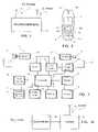
- FIG. 1is a diagrammatic depiction of a first embodiment of a communication device in accordance with the present invention
- FIG. 2is a plan view of an embodiment of a communication device in accordance with the present invention.
- FIG. 3is a block diagram of an embodiment of the communication device of FIG. 1 ;
- FIG. 4is another block diagram of an embodiment of the communication device of FIG. 1 ;
- FIG. 5is a block diagram of an embodiment of data receiver suitable for use in the communication device of FIG. 4 ;
- FIG. 6is a block diagram of a controller suitable for use in the data receiver of FIG. 5 ;
- FIG. 7is a flowchart of an embodiment of a method of indicating a telephone number identifying a telephone from which an incoming telephone call originated in accordance with the present invention
- FIG. 8is a flowchart of an embodiment of a method of operating a communication device in accordance with the present invention.
- FIG. 9is a block diagram of another embodiment of the communication device of FIG. 1 ;
- FIG. 10is a block diagram of an embodiment of a data receiver suitable for use in the communication device of FIG. 9 ;
- FIG. 11is a block diagram of a delay circuit suitable for use in the data receiver of FIG. 10 ;
- FIG. 12is a flowchart of another embodiment of a method of indicating a telephone number identifying a telephone from which an incoming telephone call originated in accordance with the present invention
- FIG. 13is a diagrammatic depiction of a another embodiment of a communication device in accordance with the present invention.
- FIG. 14is a diagrammatic depiction of still another embodiment of a communication device in accordance with the present invention.
- FIG. 1depicts a cellular combination telephone and radio 3 which includes an antenna 13 to receive telephone messages and an aerial or antenna 23 to receive radio signals according to an embodiment of the present invention. If desired, a single antenna may be provided for receipt of both the telephone messages and the radio signals.
- the cellular telephonehas a uniquely assigned telephone number such as 789-555-1234 so that telephone calls placed to that number are received by the telephone section of combination telephone and radio 3 .
- the combination telephone and radio device 3is at least dual-function in that it provides mobile telephone functionality and broadcast radio receiver functionality.
- the device 3includes a microphone 9 , a speaker 10 , display panel 11 such as a liquid crystal display (LCD), a keypad 12 and an internal antenna element 13 .
- the keypad 12includes first and second soft keys 12 a , 12 b , a bi-directional scroll key 12 c and a set of alphanumeric keys 12 d.
- a circuitry of the mobile communications device 3includes a microcontroller 14 , and memories such as a RAM/ROM 15 and a flash memory 16 . Electrical analog signals are produced by microphone 9 and amplified by an amplifier 17 . Similarly, analog audio signals are fed to speaker 10 through an amplifier 18 .
- the microcontroller 14receives instructions from the keypad 12 and controls operation of the display 11 . Information concerning the identity of the user of the mobile communications device 3 is held on a smart card 19 , for example in the form of a subscriber identity module (SIM) card for mobile telephones that conforms to the global system for mobile communications (GSM).
- SIMsubscriber identity module
- GSMglobal system for mobile communications
- Microphone 9 and speaker 10preferably are able to permit operation of combination telephone and radio 3 as a telephone in either a “private” mode, with speaker 10 adjacent the user's ear, or a “speakerphone” mode, with speaker 10 remote from the user's ear, as determined by a manual control (not shown) operated by the user.
- Communication radio signals to and from the mobile telephone networkare transmitted and received by means of antenna element 13 connected through an r.f. stage 21 to a coder/decoder (codec) 22 which is configured to process signals under the control of the microcontroller 14 .
- Broadcast radio signalsare received by internal aerial 23 connected to a tuner 24 . It will be appreciated that a single antenna can be used to feed signals to the both r.f. stage 21 and the tuner 24 . It will also be appreciated that the tuner 24 may be integrated into the r.f. stage 21 .
- the device 3is powered by a rechargeable battery 25 or other power source.
- the codec 22receives analog signals from the microphone amplifier 17 , digitizes them into a form suitable for transmission and feeds them to the r.f. stage 21 for transmission through the antenna element 13 for transmission to the mobile telephone network. Similarly, signals received from the telephone network are fed through the antenna element 13 to be demodulated by the r.f. stage 21 and fed to codec 22 so as to produce analogue signals which are fed though the amplifier 18 to speaker 10 .
- the device 3is used as a radio set, received radio signals are fed through the aerial 23 to the tuner 24 where they are demodulated and fed through the amplifier 18 to speaker 10 .
- the mobile communications device 3can be used as a mobile communications handset for voice and data services and as a radio set. These functions are controlled by microcontroller 14 and can be performed separately or simultaneously. For example, a user can send a text message while listening to the radio.
- combination telephone and radio 3preferably includes a telephone section 120 which is connected to antenna 13 and a radio section 122 which is connected to aerial 23 .
- telephone section 120 and radio section 122may be connected to a single antenna, if desired.
- Telephone section 120includes a telephone circuit 124 which is connected to antenna 113 , and to which are connected microphone 9 and an audio circuit 128 .
- Speaker 10is connected to audio circuit 128 and to radio section 122 . Alternatively, separate speakers can be provided for telephone section 120 and radio section 122 .
- telephone circuit 124When a telephone call directed to combination telephone and radio 3 is received at antenna 13 , telephone circuit 124 causes an indication of that incoming call. While a telephone call is in progress, either a call received by combination telephone and radio 3 or a call originated from combination telephone and radio 3 , the outgoing audio signals from microphone 9 are processed by telephone circuit 124 and applied to antenna 13 , while the received telephone signals are processed by telephone circuit 124 and applied through audio circuit 128 to speaker 10 .
- Telephone circuit 124further includes display 11 and keypad 12 . Signals resulting from the keypad are transmitted by antenna 13 .
- a data receiver 132is also connected to telephone circuit 124 .
- the output of data receiver 132is connected to radio section 122 .
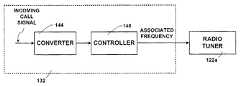
- FIG. 5is a block diagram of an embodiment of a data receiver suitable for use as data receiver 132 in telephone section 120 .
- telephone circuit 124applies an incoming call signal to data receiver 132 .
- the incoming call signalis applied to converter 144 .
- Converter 144determines whether a caller identification signal is present during the silent interval between ringing intervals. If a caller identification signal is present, converter 144 converts the caller identification signal to a serial bit stream indicative of the telephone number of the calling telephone.
- converter 144when the caller identification signal is a frequency shift keyed signal, converter 144 might include a frequency shift keyed modem connected to a frequency standard. Converter 144 applies the resulting serial bit stream to controller 148 . If no caller identification number is present, converter 144 provides a signal indicating that to controller 148 . The output of controller 148 is applied to radio tuner 122 a within radio section 122 .
- FIG. 6is a block diagram of a processing system suitable for use as controller 148 .
- the signal from converter 144is applied to a processor 150 which is connected to a program memory 152 and a data memory 154 .
- program memory 152might be a read only memory, such as an EPROM, while data memory 154 might be a random access memory.
- Data memory 154stores a list of preferred telephone numbers, together with associated radio frequencies.
- processor 150determines whether the received caller identification signal is the same as any caller identification signal stored within data memory 154 . If so, then processor 150 causes data memory 154 to output the associated frequency signal to radio tuner 122 a ( FIG.
- Data memory 154also stores a default radio frequency, and if no caller identification signal was detected, or if the caller identification signal is an unrecognized caller identification signal that is not the same as any stored in data memory 154 , then processor 150 causes data memory 154 to output the default radio frequency to radio tuner 122 a , activating the tuner at that frequency.
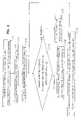
- FIG. 7is a flow chart of the operation of the combination telephone and radio 3 of FIG. 1 according to one embodiment of the present invention.
- step S 1an incoming call signal is received. Some telephones block the transmission of a caller identification signal to telephones to which calls are made, and so in step S 2 it is determined whether a caller identification signal has been received. If so, then in step S 3 the calling number is determined. In step S 4 it is determined whether the calling number is stored within data memory 154 . If so, then in step S 5 the associated radio frequency is determined, and in step S 6 , radio section 122 is tuned to the determined radio frequency.
- step S 2If the calling telephone blocked the caller identification signal, then in step S 2 no caller identification signal is received, and so the method advances to step S 7 in which radio section 122 is tuned to the default radio frequency.
- step S 4if the calling number is an unrecognized calling number that is not stored within data memory 154 , then the method advances to step S 7 and the radio section is tuned to the default frequency.
- FIG. 8is a flow chart of the operation of radio section 122 under the control of telephone section 120 according to one embodiment of the present invention.
- telephone section 120receives an incoming call or message signal.
- controller 148switches radio section 122 on, and in step S 13 , controller 148 tunes radio tuner 122 a to a particular frequency, either a frequency associated with the identified calling telephone number or the default frequency.
- controller 148determines whether a program is being broadcast on the tuned frequency. If not, then in step S 15 controller 148 tunes the tuner to another frequency, for example the default frequency. If step S 14 determines that a program is being broadcast, then in step S 16 the received broadcast is played through speaker 10 to indicate receipt of a telephone call.
- radio section 122is deactivated in step S 17 .
- FIG. 4depicts a combination telephone and radio 3 in which every incoming call results in tuning of radio section 122 to a radio frequency, either a radio frequency associated with the calling number or the default radio frequency.
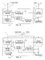
- FIG. 9is a block diagram of a combination telephone and radio 3 a in which incoming calls for which a caller identification signal can not be associated with a telephone number results in activation of a ringing circuit, rather than tuning of the radio to a default station.
- Combination telephone and radio 3 aincludes a telephone section 120 a which differs from telephone section 120 of FIG. 4 by having a ringing circuit 134 with an input connected to data receiver 132 a and an output connected to speaker 10 to provide an electronically generated ringing signal to indicate an incoming call.
- FIG. 9also illustrates that the telephone section and the radio section can utilize the same antenna 13 a.
- FIG. 10is a block diagram of an embodiment of a data receiver suitable for use as data receiver 132 a in telephone section 120 a .
- the incoming call signalis applied to interface unit 140 from which the ringing current is applied to ringing circuit 134 and to delay circuit 142 , while any caller identification signal received during the silent intervals is applied to converter 144 a .
- the output of delay circuit 142passes through OR gate 146 to a disable input of ringing circuit 134 , preventing the ringing signal of the first ringing current interval from activating ringing circuit 134 . If no caller identification signal is present, then subsequent ringing current intervals activate ringing circuit 134 .
- Converter 144 aconverts any caller identification signal to a serial bit stream and applies the serial bit stream to controller 148 .
- the output of controller 148is applied to radio tuner 122 a within radio section 122 and is applied through a second input of OR gate 146 to the disable input of ringing circuit 134 , preventing subsequent ringing current intervals from activating the ringing circuit.
- FIG. 11is a block diagram of an embodiment of a delay circuit suitable for use as delay circuit 142 in the data receiver of FIG. 10 .
- the ringing currentis applied to one input of AND gate 160 and to timer 162 .
- the output of AND gate 160is applied to the set input of flip flop 164 , the 1 output of which provides the delay signal.
- the 1 output of flip flop 164is also applied to timer 166 .
- the output of timer 166is applied to the set input of flip flop 168 and to the reset input of flip flop 164 .
- the output of timer 162is applied to the reset input of flip flop 168 .
- the 0 output of flip flop 168is applied to the second input of AND gate 160 .
- flip flops 164 and 168are reset, and so AND gate 160 is enabled.
- the ringing currentthen passes through AND gate 160 to set flip flop 164 , initiating the delay signal which disables ringing circuit 134 .
- the delay signalalso starts timer 166 which, after a time slightly greater then the duration of the first ringing current interval, sets flip flop 168 and resets flip flop 164 , ending the delay signal. Absence of the 0 output from flip flop 168 blocks further ringing current signals from passing through AND gate 160 . If the calling number has been identified, then the associated frequency signal from controller 148 passes through OR gate 146 ( FIG. 10 ) to maintain ringing circuit 134 disabled.
- That associated frequency signalalso activates radio tuner 122 a to provide an audio output of the radio station at the associated frequency. If the calling number has not been identified, ringing circuit 134 is no longer disabled, and so ringing signals during subsequent ringing current intervals activate the ringing circuit.
- the ringing signal during the first ringing current intervalalso starts timer 162 within the delay circuit of FIG. 11 .
- Timer 162times a time greater than the duration of the ringing current interval and is restarted by the ringing signal of each ringing current interval, thus maintaining flip-flop 168 set and so blocking AND gate 160 .
- timer 162resets flip flop 168 , returning the delay circuit to the quiescent condition.
- FIG. 12is a flow chart of the operation of the combination telephone and radio of FIG. 9 according to one embodiment of the present invention.
- step S 21an incoming call signal is received.
- step S 22delay circuit 142 disables ringing circuit 134 .
- step S 23it is determined whether a caller identification signal has been received. If so, then in step S 24 the calling number is determined, and in step S 25 it is determined whether the calling number is stored within data memory 154 . If so, then in step S 26 the associated radio frequency is determined, and in step S 27 , the radio section 122 is tuned to the associated frequency.
- step S 23If the calling telephone blocked the caller identification signal, then in step S 23 no caller identification signal is received, and so the method advances to step S 28 in which the ringing circuit is enabled. Likewise, in step S 25 if the calling number is not stored within data memory 154 and so is unrecognized, then the method advances to step S 28 and the ringing circuit is enabled.
- FIG. 1illustrates the present invention in the form of a cellular telephone/radio.
- FIG. 13depicts the present invention in the form of a combination telephone and radio 3 a which has a landline telephone, rather than a cellular telephone.
- FIG. 14illustrates the present invention in the form of a combination telephone and radio made up of a discrete telephone component 3 b and a discrete radio component 3 c which are coupled together by the associated frequency output line from controller 148 .
- combination telephone and radio of the present inventionhave been depicted in hardware implementations, preferably the combination telephone and radio is implemented with software on an appropriate processing system.
- the present inventionthus provides a communication device which determines whether a calling telephone number is associated with a particular radio frequency, and if so automatically tunes the radio to that frequency and which responds to SMS messages and MMS messages by tuning the radio to an associated frequency.
Landscapes
- Engineering & Computer Science (AREA)
- Signal Processing (AREA)
- Mobile Radio Communication Systems (AREA)
Abstract
Description
Claims (60)
Priority Applications (1)
| Application Number | Priority Date | Filing Date | Title |
|---|---|---|---|
| US10/051,021US7483721B1 (en) | 2002-01-22 | 2002-01-22 | Communication device providing diverse audio signals to indicate receipt of a call or message |
Applications Claiming Priority (1)
| Application Number | Priority Date | Filing Date | Title |
|---|---|---|---|
| US10/051,021US7483721B1 (en) | 2002-01-22 | 2002-01-22 | Communication device providing diverse audio signals to indicate receipt of a call or message |
Publications (1)
| Publication Number | Publication Date |
|---|---|
| US7483721B1true US7483721B1 (en) | 2009-01-27 |
Family
ID=40275468
Family Applications (1)
| Application Number | Title | Priority Date | Filing Date |
|---|---|---|---|
| US10/051,021Active2026-01-01US7483721B1 (en) | 2002-01-22 | 2002-01-22 | Communication device providing diverse audio signals to indicate receipt of a call or message |
Country Status (1)
| Country | Link |
|---|---|
| US (1) | US7483721B1 (en) |
Cited By (10)
| Publication number | Priority date | Publication date | Assignee | Title |
|---|---|---|---|---|
| US20070028262A1 (en)* | 2005-07-29 | 2007-02-01 | Zermatt Systems, Inc. | Virtual discovery of content available to a device |
| US9044543B2 (en) | 2012-07-17 | 2015-06-02 | Elwha Llc | Unmanned device utilization methods and systems |
| US9061102B2 (en) | 2012-07-17 | 2015-06-23 | Elwha Llc | Unmanned device interaction methods and systems |
| US10340034B2 (en) | 2011-12-30 | 2019-07-02 | Elwha Llc | Evidence-based healthcare information management protocols |
| US10402927B2 (en) | 2011-12-30 | 2019-09-03 | Elwha Llc | Evidence-based healthcare information management protocols |
| US10475142B2 (en) | 2011-12-30 | 2019-11-12 | Elwha Llc | Evidence-based healthcare information management protocols |
| US10528913B2 (en) | 2011-12-30 | 2020-01-07 | Elwha Llc | Evidence-based healthcare information management protocols |
| US10552581B2 (en) | 2011-12-30 | 2020-02-04 | Elwha Llc | Evidence-based healthcare information management protocols |
| US10559380B2 (en) | 2011-12-30 | 2020-02-11 | Elwha Llc | Evidence-based healthcare information management protocols |
| US10679309B2 (en) | 2011-12-30 | 2020-06-09 | Elwha Llc | Evidence-based healthcare information management protocols |
Citations (13)
| Publication number | Priority date | Publication date | Assignee | Title |
|---|---|---|---|---|
| US4582956A (en) | 1983-07-12 | 1986-04-15 | At&T Bell Laboratories | Method and apparatus for displaying at a selected station special service information during a silent interval between ringing |
| US5095503A (en) | 1989-12-20 | 1992-03-10 | Motorola, Inc. | Cellular telephone controller with synthesized voice feedback for directory number confirmation and call status |
| US5303284A (en)* | 1990-01-31 | 1994-04-12 | Nec Corporation | Ringing circuit for use in portable telephone set |
| US5841850A (en)* | 1997-03-31 | 1998-11-24 | Fan; Yuan-Neng | Intelligent caller identification apparatus for notifying a selected telephone number of the arrival of special information |
| US5867794A (en)* | 1996-09-20 | 1999-02-02 | Ericsson Inc. | Audio-output for a portable radio telephone utilizing a vehicle's AM/FM radio |
| US6181928B1 (en)* | 1997-08-21 | 2001-01-30 | Ericsson Inc. | Method and apparatus for event notification for wireless devices |
| US20030096639A1 (en)* | 2001-11-16 | 2003-05-22 | Cluff Dean K. | Distinctive recordable ringer |
| US20030119443A1 (en)* | 2000-01-14 | 2003-06-26 | Ichiro Futohashi | Portable telephone |
| US20040203944A1 (en)* | 2002-06-26 | 2004-10-14 | Nokia Corporation | Apparatus and method for facilitating physical browsing on wireless devices using radio frequency identification |
| US6961559B1 (en)* | 1998-12-31 | 2005-11-01 | At&T Corp. | Distributed network voice messaging for wireless centrex telephony |
| US7171174B2 (en)* | 2001-02-20 | 2007-01-30 | Ellis Michael D | Multiple radio signal processing and storing method and apparatus |
| US7224999B1 (en)* | 1999-09-29 | 2007-05-29 | Kabushiki Kaisha Toshiba | Radio communication terminal with simultaneous radio communication channels |
| US7257398B1 (en)* | 1999-11-12 | 2007-08-14 | Sony Corporation | Telephone set, communication adaptor, home appliance control method, and program recording medium |
- 2002
- 2002-01-22USUS10/051,021patent/US7483721B1/enactiveActive
Patent Citations (16)
| Publication number | Priority date | Publication date | Assignee | Title |
|---|---|---|---|---|
| US4582956A (en) | 1983-07-12 | 1986-04-15 | At&T Bell Laboratories | Method and apparatus for displaying at a selected station special service information during a silent interval between ringing |
| US4582956B1 (en) | 1983-07-12 | 1994-09-20 | Bell Telephone Labor Inc | Method and apparatus for displaying at a selected station special service information during a silent interval between ringing |
| US5095503A (en) | 1989-12-20 | 1992-03-10 | Motorola, Inc. | Cellular telephone controller with synthesized voice feedback for directory number confirmation and call status |
| US5303284A (en)* | 1990-01-31 | 1994-04-12 | Nec Corporation | Ringing circuit for use in portable telephone set |
| US5317622A (en)* | 1990-01-31 | 1994-05-31 | Nec Corporation | Ringing circuit for use in a telephone set for detecting a mobile mode or a portable mode of the telephone set |
| US5337356A (en)* | 1990-01-31 | 1994-08-09 | Nec Corporation | Ringing circuit for use in portable telephone set |
| US5867794A (en)* | 1996-09-20 | 1999-02-02 | Ericsson Inc. | Audio-output for a portable radio telephone utilizing a vehicle's AM/FM radio |
| US5841850A (en)* | 1997-03-31 | 1998-11-24 | Fan; Yuan-Neng | Intelligent caller identification apparatus for notifying a selected telephone number of the arrival of special information |
| US6181928B1 (en)* | 1997-08-21 | 2001-01-30 | Ericsson Inc. | Method and apparatus for event notification for wireless devices |
| US6961559B1 (en)* | 1998-12-31 | 2005-11-01 | At&T Corp. | Distributed network voice messaging for wireless centrex telephony |
| US7224999B1 (en)* | 1999-09-29 | 2007-05-29 | Kabushiki Kaisha Toshiba | Radio communication terminal with simultaneous radio communication channels |
| US7257398B1 (en)* | 1999-11-12 | 2007-08-14 | Sony Corporation | Telephone set, communication adaptor, home appliance control method, and program recording medium |
| US20030119443A1 (en)* | 2000-01-14 | 2003-06-26 | Ichiro Futohashi | Portable telephone |
| US7171174B2 (en)* | 2001-02-20 | 2007-01-30 | Ellis Michael D | Multiple radio signal processing and storing method and apparatus |
| US20030096639A1 (en)* | 2001-11-16 | 2003-05-22 | Cluff Dean K. | Distinctive recordable ringer |
| US20040203944A1 (en)* | 2002-06-26 | 2004-10-14 | Nokia Corporation | Apparatus and method for facilitating physical browsing on wireless devices using radio frequency identification |
Cited By (15)
| Publication number | Priority date | Publication date | Assignee | Title |
|---|---|---|---|---|
| US20070028262A1 (en)* | 2005-07-29 | 2007-02-01 | Zermatt Systems, Inc. | Virtual discovery of content available to a device |
| US10340034B2 (en) | 2011-12-30 | 2019-07-02 | Elwha Llc | Evidence-based healthcare information management protocols |
| US10679309B2 (en) | 2011-12-30 | 2020-06-09 | Elwha Llc | Evidence-based healthcare information management protocols |
| US10559380B2 (en) | 2011-12-30 | 2020-02-11 | Elwha Llc | Evidence-based healthcare information management protocols |
| US10552581B2 (en) | 2011-12-30 | 2020-02-04 | Elwha Llc | Evidence-based healthcare information management protocols |
| US10528913B2 (en) | 2011-12-30 | 2020-01-07 | Elwha Llc | Evidence-based healthcare information management protocols |
| US10475142B2 (en) | 2011-12-30 | 2019-11-12 | Elwha Llc | Evidence-based healthcare information management protocols |
| US10402927B2 (en) | 2011-12-30 | 2019-09-03 | Elwha Llc | Evidence-based healthcare information management protocols |
| US9254363B2 (en) | 2012-07-17 | 2016-02-09 | Elwha Llc | Unmanned device interaction methods and systems |
| US10019000B2 (en) | 2012-07-17 | 2018-07-10 | Elwha Llc | Unmanned device utilization methods and systems |
| US9798325B2 (en) | 2012-07-17 | 2017-10-24 | Elwha Llc | Unmanned device interaction methods and systems |
| US9733644B2 (en) | 2012-07-17 | 2017-08-15 | Elwha Llc | Unmanned device interaction methods and systems |
| US9713675B2 (en) | 2012-07-17 | 2017-07-25 | Elwha Llc | Unmanned device interaction methods and systems |
| US9061102B2 (en) | 2012-07-17 | 2015-06-23 | Elwha Llc | Unmanned device interaction methods and systems |
| US9044543B2 (en) | 2012-07-17 | 2015-06-02 | Elwha Llc | Unmanned device utilization methods and systems |
Similar Documents
| Publication | Publication Date | Title |
|---|---|---|
| US6216016B1 (en) | Method and system for generating and transmitting a waiting message | |
| US6804507B2 (en) | Mobile paging telephone with an automatic call back function | |
| KR100475441B1 (en) | Apparatus and method procesing calling tone of wire/wirless telephone | |
| EP1513331B1 (en) | Radiotelephone | |
| KR100713455B1 (en) | Method for receiving called call and rejecting it selectively in portable radio telephone | |
| US7483721B1 (en) | Communication device providing diverse audio signals to indicate receipt of a call or message | |
| KR0125478B1 (en) | Wireless telephone | |
| US20030078081A1 (en) | Call announcement system and method | |
| KR20010017204A (en) | Method for tone signal level control in a mobile phone | |
| KR100584362B1 (en) | How to mute reception status in wireless communication terminal | |
| JPH03213022A (en) | Wireless telephone equipment and wireless communication systems | |
| KR20010088553A (en) | A receiving sound convert sound not | |
| JP2001251672A (en) | Mobile phone and speech system for the mobile phone | |
| JP3981995B2 (en) | Communication terminal device | |
| KR20000001188A (en) | Remote control method of morning call | |
| JPH04368027A (en) | Portable telephone set | |
| KR960003104B1 (en) | Wireless calling devices for keyphone system | |
| EP0606744A1 (en) | Call management in a telecommunication system | |
| KR100267863B1 (en) | Method for confirming voice message in digital radio telephone having pager | |
| KR100439224B1 (en) | A device and a operating method of cid for manner mode mobile phone | |
| KR200254224Y1 (en) | Apparatus for announcing a cid number by voice message in a cid service telephone | |
| KR20060017153A (en) | Reservation call method in mobile terminal | |
| KR100258154B1 (en) | Cut-off sound cutoff device and method at the end of a call in a wireless telephone | |
| KR20000020442A (en) | Method for receiving dtmf signal of mobile radio terminal equipment | |
| JPH09247756A (en) | Mobile terminal equipment |
Legal Events
| Date | Code | Title | Description |
|---|---|---|---|
| AS | Assignment | Owner name:NOKIA CORPORATION, FINLAND Free format text:ASSIGNMENT OF ASSIGNORS INTEREST;ASSIGNOR:VESIKIVI, PETRI;REEL/FRAME:012505/0579 Effective date:20020118 | |
| STCF | Information on status: patent grant | Free format text:PATENTED CASE | |
| FPAY | Fee payment | Year of fee payment:4 | |
| AS | Assignment | Owner name:NOKIA TECHNOLOGIES OY, FINLAND Free format text:ASSIGNMENT OF ASSIGNORS INTEREST;ASSIGNOR:NOKIA CORPORATION;REEL/FRAME:035579/0829 Effective date:20150116 | |
| FPAY | Fee payment | Year of fee payment:8 | |
| AS | Assignment | Owner name:PROVENANCE ASSET GROUP LLC, CONNECTICUT Free format text:ASSIGNMENT OF ASSIGNORS INTEREST;ASSIGNORS:NOKIA TECHNOLOGIES OY;NOKIA SOLUTIONS AND NETWORKS BV;ALCATEL LUCENT SAS;REEL/FRAME:043877/0001 Effective date:20170912 Owner name:NOKIA USA INC., CALIFORNIA Free format text:SECURITY INTEREST;ASSIGNORS:PROVENANCE ASSET GROUP HOLDINGS, LLC;PROVENANCE ASSET GROUP LLC;REEL/FRAME:043879/0001 Effective date:20170913 Owner name:CORTLAND CAPITAL MARKET SERVICES, LLC, ILLINOIS Free format text:SECURITY INTEREST;ASSIGNORS:PROVENANCE ASSET GROUP HOLDINGS, LLC;PROVENANCE ASSET GROUP, LLC;REEL/FRAME:043967/0001 Effective date:20170913 | |
| AS | Assignment | Owner name:NOKIA US HOLDINGS INC., NEW JERSEY Free format text:ASSIGNMENT AND ASSUMPTION AGREEMENT;ASSIGNOR:NOKIA USA INC.;REEL/FRAME:048370/0682 Effective date:20181220 | |
| MAFP | Maintenance fee payment | Free format text:PAYMENT OF MAINTENANCE FEE, 12TH YEAR, LARGE ENTITY (ORIGINAL EVENT CODE: M1553); ENTITY STATUS OF PATENT OWNER: LARGE ENTITY Year of fee payment:12 | |
| AS | Assignment | Owner name:PROVENANCE ASSET GROUP LLC, CONNECTICUT Free format text:RELEASE BY SECURED PARTY;ASSIGNOR:CORTLAND CAPITAL MARKETS SERVICES LLC;REEL/FRAME:058983/0104 Effective date:20211101 Owner name:PROVENANCE ASSET GROUP HOLDINGS LLC, CONNECTICUT Free format text:RELEASE BY SECURED PARTY;ASSIGNOR:CORTLAND CAPITAL MARKETS SERVICES LLC;REEL/FRAME:058983/0104 Effective date:20211101 Owner name:PROVENANCE ASSET GROUP LLC, CONNECTICUT Free format text:RELEASE BY SECURED PARTY;ASSIGNOR:NOKIA US HOLDINGS INC.;REEL/FRAME:058363/0723 Effective date:20211129 Owner name:PROVENANCE ASSET GROUP HOLDINGS LLC, CONNECTICUT Free format text:RELEASE BY SECURED PARTY;ASSIGNOR:NOKIA US HOLDINGS INC.;REEL/FRAME:058363/0723 Effective date:20211129 | |
| AS | Assignment | Owner name:RPX CORPORATION, CALIFORNIA Free format text:ASSIGNMENT OF ASSIGNORS INTEREST;ASSIGNOR:PROVENANCE ASSET GROUP LLC;REEL/FRAME:059352/0001 Effective date:20211129 | |
| AS | Assignment | Owner name:BARINGS FINANCE LLC, AS COLLATERAL AGENT, NORTH CAROLINA Free format text:PATENT SECURITY AGREEMENT;ASSIGNOR:RPX CORPORATION;REEL/FRAME:063429/0001 Effective date:20220107 | |
| AS | Assignment | Owner name:RPX CORPORATION, CALIFORNIA Free format text:RELEASE OF LIEN ON PATENTS;ASSIGNOR:BARINGS FINANCE LLC;REEL/FRAME:068328/0278 Effective date:20240802 | |
| AS | Assignment | Owner name:BARINGS FINANCE LLC, AS COLLATERAL AGENT, NORTH CAROLINA Free format text:PATENT SECURITY AGREEMENT;ASSIGNORS:RPX CORPORATION;RPX CLEARINGHOUSE LLC;REEL/FRAME:068328/0674 Effective date:20240802 |