US7483528B2 - Loop extender with selectable line termination and equalization - Google Patents
Loop extender with selectable line termination and equalizationDownload PDFInfo
- Publication number
- US7483528B2 US7483528B2US10/072,833US7283302AUS7483528B2US 7483528 B2US7483528 B2US 7483528B2US 7283302 AUS7283302 AUS 7283302AUS 7483528 B2US7483528 B2US 7483528B2
- Authority
- US
- United States
- Prior art keywords
- local loop
- coupled
- loop
- upstream
- downstream
- Prior art date
- Legal status (The legal status is an assumption and is not a legal conclusion. Google has not performed a legal analysis and makes no representation as to the accuracy of the status listed.)
- Active, expires
Links
Images


Classifications
- H—ELECTRICITY
- H04—ELECTRIC COMMUNICATION TECHNIQUE
- H04L—TRANSMISSION OF DIGITAL INFORMATION, e.g. TELEGRAPHIC COMMUNICATION
- H04L5/00—Arrangements affording multiple use of the transmission path
- H04L5/14—Two-way operation using the same type of signal, i.e. duplex
- H04L5/143—Two-way operation using the same type of signal, i.e. duplex for modulated signals
- H—ELECTRICITY
- H04—ELECTRIC COMMUNICATION TECHNIQUE
- H04L—TRANSMISSION OF DIGITAL INFORMATION, e.g. TELEGRAPHIC COMMUNICATION
- H04L25/00—Baseband systems
- H04L25/02—Details ; arrangements for supplying electrical power along data transmission lines
- H04L25/0264—Arrangements for coupling to transmission lines
- H—ELECTRICITY
- H04—ELECTRIC COMMUNICATION TECHNIQUE
- H04L—TRANSMISSION OF DIGITAL INFORMATION, e.g. TELEGRAPHIC COMMUNICATION
- H04L25/00—Baseband systems
- H04L25/02—Details ; arrangements for supplying electrical power along data transmission lines
- H04L25/03—Shaping networks in transmitter or receiver, e.g. adaptive shaping networks
- H04L25/03878—Line equalisers; line build-out devices
- H—ELECTRICITY
- H04—ELECTRIC COMMUNICATION TECHNIQUE
- H04L—TRANSMISSION OF DIGITAL INFORMATION, e.g. TELEGRAPHIC COMMUNICATION
- H04L25/00—Baseband systems
- H04L25/02—Details ; arrangements for supplying electrical power along data transmission lines
- H04L25/20—Repeater circuits; Relay circuits
- H04L25/22—Repeaters for converting two wires to four wires; Repeaters for converting single current to double current
- H—ELECTRICITY
- H04—ELECTRIC COMMUNICATION TECHNIQUE
- H04L—TRANSMISSION OF DIGITAL INFORMATION, e.g. TELEGRAPHIC COMMUNICATION
- H04L25/00—Baseband systems
- H04L25/02—Details ; arrangements for supplying electrical power along data transmission lines
- H04L25/20—Repeater circuits; Relay circuits
- H04L25/24—Relay circuits using discharge tubes or semiconductor devices
- H—ELECTRICITY
- H04—ELECTRIC COMMUNICATION TECHNIQUE
- H04L—TRANSMISSION OF DIGITAL INFORMATION, e.g. TELEGRAPHIC COMMUNICATION
- H04L5/00—Arrangements affording multiple use of the transmission path
- H04L5/14—Two-way operation using the same type of signal, i.e. duplex
- H04L5/1461—Suppression of signals in the return path, i.e. bidirectional control circuits
- H—ELECTRICITY
- H04—ELECTRIC COMMUNICATION TECHNIQUE
- H04M—TELEPHONIC COMMUNICATION
- H04M11/00—Telephonic communication systems specially adapted for combination with other electrical systems
- H04M11/06—Simultaneous speech and data transmission, e.g. telegraphic transmission over the same conductors
- H04M11/062—Simultaneous speech and data transmission, e.g. telegraphic transmission over the same conductors using different frequency bands for speech and other data
- H—ELECTRICITY
- H04—ELECTRIC COMMUNICATION TECHNIQUE
- H04M—TELEPHONIC COMMUNICATION
- H04M3/00—Automatic or semi-automatic exchanges
- H04M3/005—Interface circuits for subscriber lines
- H04M3/007—Access interface units for simultaneous transmission of speech and data, e.g. digital subscriber line [DSL] access interface units
Definitions
- the present system and methodrelate generally to Digital Subscriber Line (DSL) technology, and more particularly to a system and method for improving ADSL (Asymmetric DSL) and VDSL (Very high data rate DSL) system performance over long local loops.
- DSLDigital Subscriber Line
- ADSLAsymmetric DSL
- VDSLVery high data rate DSL
- ADSLis one version of DSL technology that expands the useable bandwidth of existing copper telephone lines.
- ADSLis “asymmetric” in that ADSL reserves more bandwidth in one direction than in the other, which may be beneficial for users who do not require equal bandwidth in both directions.
- ADSL signalsgenerally occupy the frequency band between about 25 kHz and 1.104 MHz. In this configuration, ADSL uses the frequency band between about 25 kHz and 120 kHz to transmit upstream signals (signals from a customer premises to a central office) and the frequency band between about 150 kHz to 1.104 MHz to transmit downstream signals (signals from the central office to a customer premises).
- ADSLemploys Frequency Division Multiplexing (FDM) to separate upstream and downstream signals and to separate ADSL signals from POTS (Plain Old Telephone Service) band signals, which reside below 4 kHz.
- FDMFrequency Division Multiplexing
- VDSLalso uses FDM to separate downstream and upstream channels as well as to separate both downstream and upstream channels from POTS signals.
- ADSLhas been used to deliver high-speed data services to subscribers up to about 18,000 feet from their serving central office or central office extension.
- the potential data ratesrange from above about 8 MBPS for short loops, but drop off dramatically on long loops, such as local loops over about 18,000 feet, to about 0.5 MBPS or less.
- ADSL servicegenerally employs a local loop length of about 6,000-14,000 feet for optimal service. Loop length is generally defined as the length of the wire between the central office, or central office extension, and the customer premises, such as a home or business.
- Central office and “central office extension”are collectively referred to herein as “central office.”
- DSL signalsgenerally degrade as they traverse the local loop. Hence, the longer the local loop length, the more degraded the DSL signal will tend to be upon arriving at a central office or a customer premises. While some DSL service is conventionally possible with loop lengths longer than 14,000 feet, it has been found that with loops much longer than about 14,000 feet, the DSL signal is too degraded to provide high data transfer rates.
- DSL signal degradation over a local loopmay be caused, for example, by factors such as: signal attenuation, crosstalk, thermal noise, impulse noise, and ingress noise from commercial radio transmitters.
- the dominant impairment, however,is often signal attenuation.
- a transmitted ADSL signalcan suffer as much as 60 dB or more of attenuation on long loops, which substantially reduces the useable signal, greatly reducing potential data rates.
- a loop extenderfor improving the transmission of DSL signals over a local loop.
- the loop extenderincludes selectable line termination and equalization (SLTE) DSL amplification circuitry capacitively coupled to the local loop via bypass relay switches, a POTS loading coil adapted to be coupled to the local loop for improving transmission of POTS band signals over the local loop, and a diagnostic/control unit (DCU) coupled to the local loop for receiving and processing control signals from a central office, coupled to the bypass relay switches via a bypass relay for controlling the bypass relay switches, and coupled to the SLTE DSL amplification circuitry via a plurality of switch control lines for controlling the SLTE DSL amplification circuitry.
- SLTEselectable line termination and equalization
- DCUdiagnostic/control unit
- the SLTE DSL amplification circuitryincludes a plurality of upstream complex impedances coupled in parallel and selectable via a first switch, a plurality of downstream complex impedances coupled in parallel and selectable via a second switch, a plurality of upstream filter/amplifying elements coupled in parallel and selectable via a third switch, and a plurality of downstream filter/amplifying elements coupled in parallel and selectable via a fourth switch.
- the first switchis controlled via a first switch control line
- the second switchis controlled via a second switch control line
- the third switchis controlled via a third switch control line
- the fourth switchis controlled via a fourth switch control line.
- the DCUincludes a modem coupled to the local loop for communication with the central office, an analog multiplexer/analog-to-digital converter (AMADC) for controlling the first, second, third, and fourth switches via the switch control lines, and a diagnostic/control processor (DCP) coupled to the modem and the AMADC for processing control signals received via the modem and sending the control signals to the AMADC.
- AMADCanalog multiplexer/analog-to-digital converter
- DCPdiagnostic/control processor
- the DCUin response to the control signals received from the central office, instructs the first switch to select one of the plurality of complex upstream impedances.
- the DCUinstructs the first switch to select a complex upstream impedance that approximately matches the local loop impedance in a first direction along the local loop, where the first direction is directed from the SLTE DSL amplification circuitry to the central office along the local loop.
- the DCUinstructs the second switch to select one of the plurality of complex downstream impedances, the third switch to select one of the plurality of upstream filter/amplifying elements, and the fourth switch to select one of the plurality of downstream filter/amplifying elements.
- the loop extenderincludes a bypass relay for coupling the bypass relay switches to the DCU.
- the DCUin accordance with the control signals received from the central office, may uncouple the SLTE DSL amplification circuitry from the local loop by activating a deactivated bypass relay, or the DCU may couple the SLTE DSL amplification circuitry to the local loop by deactivating an activated bypass relay.
- the DCUmay sample DSL signals within the SLTE DSL amplification circuitry, process the sampled DSL signals, and select SLTE DSL amplification circuitry switch states in accordance with the processed sampled DSL signals to improve SLTE DSL amplification circuitry performance.
- FIG. 1is a graph illustrating one example of DSL signal attenuation over a 6,000-foot length of telephone cable as a function of signal frequency;
- FIG. 2illustrates multiple local loops interconnecting a central office and multiple customer premises with each local loop having at least one loop extender coupled thereto;
- FIG. 3illustrates one embodiment of a FIG. 2 loop extender
- FIG. 4illustrates another embodiment of a FIG. 2 loop extender
- FIG. 5illustrates another embodiment of a FIG. 4 loop extender with selectable line termination and equalization
- FIG. 6illustrates another embodiment of a FIG. 5 loop extender with communications, control, and diagnostics functionality.
- FIG. 1illustrates an example of the attenuation of a DSL signal over 6,000 feet of 26 AWG (American Wire Gauge) telephone cable. As shown, higher frequency signals are generally attenuated more than lower frequency signals. In the FIG. 1 example, a 250 kHz signal is attenuated by about 25 dB over 6,000 feet of 26 AWG telephone cable while a 1 MHz signal is attenuated by about 46 dB over 6,000 feet of 26 AWG telephone cable. As those skilled in the art will appreciate, the actual degree of attenuation will also depend on factors in addition to loop length, such as temperature.
- FIG. 2illustrates a DSL network 200 that includes a central office 202 , a customer premises A 204 , a customer premises B 206 , a customer premises C 208 , and a customer premises N 210 .
- Customer premises 204 , 206 , 208 , and 210are respectively coupled to central office 202 by local loops 214 , 216 , 218 , and 220 .
- Each local loopcomprises a twisted pair of copper wires; commonly know in the art as a “twisted pair.”
- the copper wiresare formed of 22, 24, or 26 AWG wire.
- central office 202 and each of customer premises 204 , 206 , 208 , and 210includes a DSL termination device, such as a DSL modem, for transmitting and receiving DSL signals over an associated local loop.
- a DSL termination devicesuch as a DSL modem
- a loop extender 224also called a DSL repeater, is coupled to local loop 214 to amplify DSL signals, such as ADSL or VDSL signals, passing over local loop 214 between central office 202 and customer premises 204 .
- DSL signalsare generally attenuated as they travel along a local loop, such as local loop 214 .
- Loop extender 224is disposed along local loop 214 between central office 202 and customer premises 204 to at least partially compensate for the DSL signal attenuation by amplifying the transmitted DSL signals. Additional details of loop extender 224 are described below with reference to FIGS. 3-6 .
- a loop extender 226is coupled to local loop 216 between central office 202 and customer premises 206 to amplify DSL signals passing between central office 202 and customer premises 206 .
- a loop extender 230is disposed between central office 202 and customer premises 210 to amplify DSL signals passing therebetween. Loop extenders 226 and 230 are configured the same as loop extender 224 .
- FIG. 2illustrates that multiple loop extenders may be coupled in series, or in cascaded fashion, to a single loop for amplifying transmitted DSL signals multiple times and in multiple locations between a customer premises and central office 202 to permit DSL signals to be transmitted over greater distances while still maintaining an acceptable DSL signal amplitude.
- loop extender 228 and loop extender 229are coupled in series to local loop 218 , which couples central office 202 and customer premises 208 .
- loop extender 228first amplifies a downstream DSL signal transmitted from central office 202 over local loop 218 to customer premises 208 and loop extender 229 then amplifies the downstream signal again.
- loop extender 228amplifies the downstream signal to at least partially compensate for the attenuation incurred as the downstream signal passes over the portion of local loop 218 between central office 202 and loop extender 228 .
- loop extender 229amplifies the downstream signal to at least partially compensate for the attenuation incurred as the downstream signal passes from loop extender 228 to loop extender 229 .
- loop extender 229amplifies the upstream signals to at least partially compensate for the attenuation that occurs between customer premises 208 and loop extender 229 .
- loop extender 228amplifies the upstream signal to at least partially compensate for the attenuation incurred as the upstream signal passes from loop extender 229 over local loop 218 to loop extender 228 .
- loop distance between loop extenders 228 and 229is between about 5,000 and 7,000 feet. In a preferred embodiment, the loop distance between loop extenders 228 and 229 is about 6,000 feet. As discussed in more detail below, this loop distance between multiple loop extenders disposed in series, in cascaded fashion, along a single local loop may be advantageous in that each loop extender may be adapted with POTS loading coils. These embodiments may then replace conventional POTS loading coils, which are disposed about every 6,000 feet along a local loop to provide both POTS loading and DSL signal amplification functionality. Additional details of adapting POTS loading coils to loop extenders are discussed below with reference to FIGS. 3-6 .
- Local loop 218is illustrated as having two cascaded loop extenders 228 and 229 coupled thereto between central office 202 and customer premises 208 . It should be noted, however, that additional loop extenders (not shown) may be disposed in series between central office 202 and customer premises 208 so that DSL signals may be effectively transmitted over an even longer local loop 218 by being amplified multiple times by multiple loop extenders.
- loop extenders 224 , 226 , 228 , and 230receive electrical power from a power supply 240 , which preferably receives power over a twisted pair 242 from central office 202 .
- Twisted pair 242is a dedicated twisted pair that delivers DC current to power supply 240 in the same manner in which electrical power is conventionally provided to T1 line repeaters.
- loop extender 229may receive power from a separate dedicated twisted pair or may receive power from power supply 240 .
- power supply 240 ; loop extenders 224 , 226 , 228 , and 230 ; and the associated circuitrymay be disposed in a common housing 250 .
- FIG. 3illustrates details of one embodiment of loop extender 224 of FIG. 2 .
- loop extender 224is coupled to local loop 214 between central office 202 and customer premises 204 .
- Loop extender 224is depicted as including a downstream filter 302 , a downstream amplifying element or stage 304 , an upstream filter 312 , an upstream amplifying element or stage 314 , a complex impedance Zload 1 306 , a complex impedance Zload 2 307 , a transformer 322 with a split secondary winding, a transformer 324 with a split secondary winding, and POTS loading coils 308 .
- Transformers with a split secondary windingare also known as center-tapped transformers.
- Filters 302 and 312 , amplifying elements 304 and 314 , and complex impedances 306 and 307are disposed between transformers 322 and 324 .
- Amplifying elements 304 and 314may comprise amplifiers or amplifying equalizers. More details regarding the functionality and operational characteristics of filters 302 and 312 , amplifying elements 304 and 314 , complex impedances 306 and 307 , and transformers 322 and 324 are disclosed in U.S. patent application Ser. No. 09/569,470, filed on May 12, 2000 and entitled “DSL Repeater.”
- Transformer 322is capacitively coupled to local loop 214 on the central office side of POTS loading coils 308 along lines 360 and 362 .
- a capacitor 364(100 nF) is disposed along line 360 and a capacitor 366 (100 nF) is disposed along line 362 to capacitively couple transformer 322 to local loop 214 on the central office side of POTS loading coils 308 .
- transformer 324is capacitively coupled to local loop 214 on the customer premises side of POTS loading coils 308 along lines 368 and 370 .
- a capacitor 372(100 nF) is disposed along line 368 and a capacitor 374 (100 nF) is disposed along line 370 to capacitively couple transformer 324 to local loop 214 on the customer premises side of POTS loading coils 308 .
- transformer 322receives downstream DSL signals from central office 202 along local loop 214 and outputs the downstream DSL signals to downstream filter 302 along a line 332 .
- Transformer 322also receives amplified upstream DSL signals from upstream amplifying element 314 along a line 334 and outputs the upstream DSL signals onto local loop 214 for transmission to central office 202 .
- transformer 324receives upstream DSL signals from customer premises 204 along local loop 214 and outputs the upstream DSL signals to upstream filter 312 along a line 342 .
- Transformer 324also receives amplified downstream DSL signals from downstream amplifying element 304 along a line 344 and outputs the downstream DSL signals onto local loop 214 for transmission to customer premises 204 .
- transformer 322is imperfect, at least a portion of the upstream amplified DSL signal received via line 334 will leak through transformer 322 onto line 332 .
- transformer 324is imperfect, at least a portion of the downstream amplified DSL signal received via line 344 will leak through transformer 324 onto line 342 . Without the presence of filters 302 and 312 , this DSL signal leakage could cause a phenomenon known in the art as “singing”—that is oscillations caused by introducing gain into a bi-directional system due to signal leakage.
- ADSL upstream signalsgenerally occupy the frequency spectrum between about 25-120 kHz and ADSL downstream signals generally occupy the frequency spectrum between about 150 kHz-1.104 MHz.
- Downstream filter 302substantially prevents leaked upstream signals from being transmitted back to customer premises 204 by significantly attenuating signals between 25 kHz and 120 kHz for ADSL.
- upstream filter 312is configured to provide significant attenuation to signals between about 150 kHz-1.104 MHz for ADSL.
- filters 302 and 312respectively attenuate signals outside the downstream and upstream frequency bands, although the limits of these bands may be different than those for the ADSL variety.
- loop extender 224receives upstream DSL signals from customer premises 204 via transformer 324 , filters out, or substantially attenuates, signals in the downstream frequency band with upstream filter 312 and then passes the filtered upstream signal to upstream amplifying element 314 via a line 352 for amplification. Loop extender 224 then passes the amplified upstream DSL signal onto local loop 214 for transmission to central office 202 .
- loop extender 224receives downstream DSL signals from central office 202 via transformer 322 , filters out, or substantially attenuates, signals in the upstream frequency band with downstream filter 302 and then passes the filtered downstream signal to downstream amplifying element 304 via a line 354 for amplification. Loop extender 224 then passes the amplified downstream DSL signal onto local loop 214 for transmission to customer premises 204 .
- loop extender 224includes POTS loading coils 308 coupled to local loop 214 to improve transmission of voice, or POTS, frequency signals over long local loop lengths, such as those longer than about 18,000 feet.
- POTS loading coils 308comprise loading coils having an inductance of about 88 mH.
- Loop extender 224 of FIG. 3may be advantageously employed in circumstances where local loop 214 already has conventional POTS loading coils coupled thereto. In this circumstance, loop extender 224 of FIG. 3 may simply replace the conventional POTS loading coils to provide both POTS loading coils and DSL signal amplification functionality. Indeed, POTS loading coils are conventionally disposed about every 6,000 feet along some long local loops to improve voice frequency transmission over long local loops. By replacing these conventional POTS loading coils with loop extender 224 of FIG. 3 , a single device, namely loop extender 224 of FIG. 3 , may provide both voice frequency transmission improvement and DSL signal amplification. Moreover, replacing existing POTS loading coils with loop extender 224 of FIG. 3 permits loop extender 224 to potentially use any housing or other hardware (not shown) associated with the previously existing POTS loading coils, thereby potentially facilitating installation of loop extender 224 of FIG. 3 along local loop 214 .
- FIG. 4illustrates details of another embodiment of loop extender 224 of FIG. 2 .
- Loop extender 224is depicted as including a downstream filter/amplifying element 402 , an upstream filter/amplifying element 404 , a complex impedance Zload 1 406 , a complex impedance Zload 2 408 , inverting buffers 410 and 412 , non-inverting buffers 414 and 416 , non-center-tapped transformers 418 and 420 , and POTS loading coils 308 .
- non-center-tapped transformersare also referred to as single-ended transformers and the FIG. 4 embodiment of loop extender 224 is referred to as a single-ended loop extender.
- FIG. 4shows filtering and amplification functions combined as discrete filter/amplifying elements ( 402 and 404 ), the scope of the present invention includes loop extenders with separate filter and amplifying elements.
- the impedance seen looking into transformer 420 from lines 368 and 370is approximately Zload 2 408 , since inverting buffer 412 and non-inverting buffer 416 are zero impedance AC ground to upstream DSL signals.
- Zload 2 408is approximately matched to the impedance seen looking into lines 368 and 370 from transformer 420 and Zload 1 406 is approximately matched to the impedance seen looking into lines 360 and 362 from transformer 418 .
- transformer 420receives an upstream DSL signal from local loop 214 and sends the upstream DSL signal to upstream filter/amplifying element 404 via upstream line 422 .
- Upstream filter/amplifying element 404then filters and amplifies the upstream DSL signal, and sends the filtered and amplified signal to non-inverting buffer 414 .
- Non-inverting buffer 414sends the DSL signal to Zload 1 406 and inverting buffer 410 .
- Inverting buffer 410inverts the DSL signal.
- the output of inverting buffer 410is 180 degrees out of phase with the output of non-inverting buffer 414 .
- non-inverting and inverting buffers( 414 and 410 ) then drive the serial combination of transformer 418 and Zload 1 406 .
- the serial combination of transformer 418 and Zload 1 406is driven with a differential signal that is symmetric about ground, and since Zload 1 406 is approximately matched to the impedance seen looking into lines 360 and 362 from transformer 418 , a residual upstream voltage RXu approximately equal to zero is developed on downstream line 424 . That is, loop extender 224 of FIG.
- loop extender 224In the process of coupling the upstream DSL signal to the central office side of local loop 214 , loop extender 224 generates a residual upstream voltage RXu approximately equal to zero on the downstream line 424 . In addition, loop extender 224 of FIG. 4 filters and amplifies the upstream DSL signal.
- transformer 418receives a downstream DSL signal from the central office side of local loop 214 and sends the downstream DSL signal to downstream filter/amplifying element 402 via downstream line 424 .
- Downstream filter/amplifying element 402filters and amplifies the DSL signal and sends the filtered and amplified DSL signal to non-inverting buffer 416 .
- Non-inverting buffer 416sends the DSL signal to inverting buffer 412 and Zload 2 408 .
- the symmetric, differential output of inverting and non-inverting buffers( 412 and 416 ) then drives the serial combination of Zload 2 408 and transformer 420 , coupling the downstream DSL signal to the customer premises side of the local loop 214 and generating a residual downstream voltage RXd on the upstream line 422 . If Zload 2 408 is approximately matched to the line impedance seen by transformer 420 , then residual downstream voltage RXd generated on upstream line 422 is approximately equal to zero.
- the amount of residual voltage RXu generated by the coupling of upstream DSL signals to the central office side of local loop 214 via transformer 418 and the amount of residual voltage RXd generated by the coupling of downstream DSL signals to the customer premises side of local loop 214 via transformer 420depend upon how closely Zload 1 406 and Zload 2 408 match line impedances ( 360 , 362 ) and ( 368 , 370 ), respectively.
- Loop extender 224generates small residual voltages (RXu and RXd) when complex impedances ( 406 and 408 ) approximately match the line impedances. In other words, close matching between complex impedances ( 406 and 408 ) and line impedances provides for stable operation of a high-gain loop extender. If complex impedances ( 406 and 408 ) do not closely match the line impedances, positive feedback of residual voltages (RXu and RXd) may lead to unstable loop extender performance.
- Line impedance seen from loop extender 224depends upon line gauge of the local loop (26 or 24 AWG, typically), length of the local loop from the loop extender to the next device (3000 or 6000 feet, typically), and the impedance of the next device.
- the next deviceis typically another loop extender or a DSL termination unit (DSL modem) located in either central office 202 or in customer premises 204 . If the next device is a DSL termination unit, the termination impedance is typically 100 ohms resistive. However, if the next device is another loop extender, the impedance is a complex impedance defined by the design of the other loop extender.
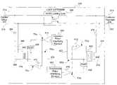
- FIG. 5illustrates another embodiment of loop extender 224 of FIG. 4 with selectable line termination and equalization (SLTE) functionality.
- the FIG. 5 embodiment of loop extender 224includes POTS loading coils 308 and SLTE DSL amplification circuitry 505 capacitively coupled to local loop 214 between central office 202 and customer premises 204 .
- SLTE DSL amplification circuitry 505includes a plurality of upstream complex impedances 406 selectable via switch 510 , a plurality of downstream complex impedances 408 selectable via switch 512 , a plurality of upstream filter/amplifying elements 404 selectable via switch 511 , a plurality of downstream filter/amplifying elements 402 selectable via switch 513 , and switch control lines 516 , 518 , 520 , and 522 .
- loop extender 224is configured with a plurality of upstream complex impedances (Zload 1 406 a , Zload 2 406 b , Zload 3 406 c , and Zloadn 406 d ) to approximate various line impedances seen from transformer 418 and with a plurality of downstream complex impedances (Zload 1 408 a , Zload 2 408 b , Zload 3 408 c , Zloadn 408 d ) to approximate various line impedances seen from transformer 420 .
- a plurality of upstream complex impedancesZload 1 406 a , Zload 2 406 b , Zload 3 406 c , and Zloadn 406 d
- switch 510may select either Zload 1 406 a , Zload 2 406 b , Zload 3 406 c , or Zloadn 406 d to approximately match an upstream line impedance seen from transformer 418 and switch 512 may select either Zload 1 408 a , Zload 2 408 b , Zload 3 408 c , or Zloadn 408 d to approximately match a downstream line impedance seen from transformer 420 .
- FIG. 5illustrates four upstream complex impedances and four downstream complex impedances, the scope of the invention covers loop extenders with any number of upstream and downstream complex or resistive impedances.
- loop extender 224is also configured with a plurality of upstream filter/amplifying elements ( 404 a , 404 b ) and downstream filter/amplifying elements ( 402 a , 402 b ) to allow a user of loop extender 224 flexibility in DSL signal processing.
- a first filter/amplifying element applied to a DSL signal to compensate for DSL signal transmission losses along 3000 feet of wiremay be significantly different than a second filter/amplifying element applied to a DSL signal to compensate for transmission losses along 6000 feet of wire.
- the selection of filter/amplifying elements 404 and 402 by switches 511 and 513depend upon line gauge, line length, and temperature, and is typically independent of line impedance and upstream and downstream complex impedances 406 and 408 selected via switches 510 and 512 .
- switches 510 - 513are rotary or dip switches that are set by a technician or operator. The technician or operator may set the switches in accordance with local line conditions upon installation of loop extender 224 , and may reset the switches as local line conditions change.
- switches 510 - 513are electronic switches controlled by an on-board microprocessor and switch control lines 516 , 518 , 520 , and 522 .
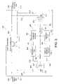
- FIG. 6illustrates another embodiment of loop extender 224 of FIG. 5 with selectable line termination and equalization controlled by an on-board microprocessor.
- Loop extender 224 of FIG. 6includes SLTE DSL amplification circuitry 505 for amplifying the DSL signals and a diagnostic/control unit (DCU) 602 for controlling the SLTE DSL amplification circuitry 505 .
- DCU 602includes a VF modem 610 , a diagnostic/control processor (DCP) 612 , and an analog Mux/AD Converter (AMADC) 614 connected in series.
- DCPdiagnostic/control processor
- AMADCanalog Mux/AD Converter
- VF modem 610receives control signals from central office 202 and sends response signals and data to central office 202 via local loop 214 .
- DCP 612processes the control signals received from central office 202 via VF modem 610 , sends the processed control signals to AMACD 614 , receives data from AMADC 614 , analyzes some or all of the received data, and sends the analyzed and unanalyzed data to central office 202 via VF modem 610 .
- AMADC 614controls the state of switches 510 , 511 , 512 , and 513 via switch control lines 516 , 518 , 520 , and 522 respectively upon receiving the processed control signals from DCP 612 .
- AMADC 614may also sample DSL signal data at locations (not shown) in the SLTE DSL amplification circuitry 505 via a plurality of diagnostic lines 614 , convert the sampled signal data to analog data, and send the converted signal data to DCP 612 for analysis.
- the sampling of DSL signal data via diagnostic lines 614 and the communications, control, and diagnostics functionality of loop extender 224 and central office 202is disclosed in a U.S. patent application Ser. No. 10/072,091 entitled “Loop Extender with Communications, Control and Diagnostics” filed on Feb. 6, 2002, the disclosure of which is hereby incorporated by reference.
- central office 202issues control signals to DCP 612 via local loop 214 .
- Control signals issued by central office 202may be based upon performance characteristics of loop extender 224 , desired DSL signal amplification of loop extender 224 , or local line conditions, for example.
- DCP 612receives and processes the control signals and instructs AMADC 614 to select a state for each switch 510 - 513 via switch control lines 516 , 518 , 520 , and 522 .
- SLTE DSL amplification circuitry 505is electrically coupled to local loop 214 via switches 606 .
- DCP 612upon receiving control signals from central office 202 , may decouple SLTE DSL amplification circuitry 505 from local loop 214 by activating bypass relay 604 .
- bypass relayWhen bypass relay is activated, switches 606 are open and SLTE DSL amplification circuitry 505 is electrically decoupled from local loop 214 .
- selectable line termination and equalizationis an automated procedure, based upon DSL signal data sampled by AMADC 614 at locations within SLTE DSL amplification circuitry 505 via diagnostic lines 614 .
- AMADC 614samples DSL signal data from SLTE DSL amplification circuitry 505 via diagnostic lines 614 , and sends the sampled DSL signal data to DCP 612 .
- DCP 612analyzes the sampled DSL signal data to determine loop extender performance, and based upon the analyzed DSL signal data, may instruct AMADC 614 to select alternate states of switches 510 - 513 via switch control lines 516 , 518 , 520 , and 522 to improve loop extender performance.
- DCP 612sends the sampled DSL signal data to central office 202 for further processing and evaluation. Central office 202 then issues control signals to DCP 612 via local loop 214 to select alternate states of switches 510 - 513 .
- the plurality of complex impedancesmay be configured as sub-elements of a single impedance circuit block (not shown).
- the plurality of upstream filter/amplifying elements 404 and downstream filter/amplifying elements 402may be configured as sub-elements of a single upstream amplification/filtering network circuit block and a single downstream amplification/filtering network circuit block, respectively.
- Switches 510 - 513then select between the various sub-elements of the circuit blocks.
Landscapes
- Engineering & Computer Science (AREA)
- Signal Processing (AREA)
- Computer Networks & Wireless Communication (AREA)
- Power Engineering (AREA)
- Cable Transmission Systems, Equalization Of Radio And Reduction Of Echo (AREA)
- Small-Scale Networks (AREA)
Abstract
Description
Claims (23)
Priority Applications (1)
| Application Number | Priority Date | Filing Date | Title |
|---|---|---|---|
| US10/072,833US7483528B2 (en) | 2001-02-06 | 2002-02-06 | Loop extender with selectable line termination and equalization |
Applications Claiming Priority (2)
| Application Number | Priority Date | Filing Date | Title |
|---|---|---|---|
| US26695301P | 2001-02-06 | 2001-02-06 | |
| US10/072,833US7483528B2 (en) | 2001-02-06 | 2002-02-06 | Loop extender with selectable line termination and equalization |
Publications (2)
| Publication Number | Publication Date |
|---|---|
| US20020106013A1 US20020106013A1 (en) | 2002-08-08 |
| US7483528B2true US7483528B2 (en) | 2009-01-27 |
Family
ID=23016663
Family Applications (1)
| Application Number | Title | Priority Date | Filing Date |
|---|---|---|---|
| US10/072,833Active2026-01-24US7483528B2 (en) | 2001-02-06 | 2002-02-06 | Loop extender with selectable line termination and equalization |
Country Status (3)
| Country | Link |
|---|---|
| US (1) | US7483528B2 (en) |
| EP (1) | EP1358737A4 (en) |
| WO (1) | WO2002063833A2 (en) |
Families Citing this family (16)
| Publication number | Priority date | Publication date | Assignee | Title |
|---|---|---|---|---|
| US7697507B2 (en)* | 1999-05-27 | 2010-04-13 | Infineon Technologies Ag | Ethernet transport over a telephone line |
| US6977958B1 (en)* | 2000-02-23 | 2005-12-20 | 2Wire, Inc. | Differentially-driven loop extender |
| EP1358731A4 (en)* | 2001-02-06 | 2005-08-24 | 2Wire Inc | Line powered loop extender with communications, control, and diagnostics |
| EP1358737A4 (en) | 2001-02-06 | 2009-12-02 | 2Wire Inc | Loop extender with selectable line termination and equalization |
| EP1378107A4 (en)* | 2001-02-06 | 2006-04-12 | 2Wire Inc | Loop extender with communications, control, and diagnostics |
| EP1370879A4 (en) | 2001-02-15 | 2006-04-26 | 2Wire Inc | System and method for fault isolation for dsl loop extenders |
| CN2487163Y (en)* | 2001-07-10 | 2002-04-17 | 蒋泽民 | Ether net long line driver |
| CA2374370A1 (en)* | 2002-03-04 | 2003-09-04 | Northern Airborne Technology Ltd. | Universal tie line adapter |
| US7302017B2 (en)* | 2002-06-18 | 2007-11-27 | General Dynamics C4 Systems, Inc. | System and method for adaptive matched filter signal parameter measurement |
| DE10240140A1 (en)* | 2002-08-30 | 2004-03-25 | Siemens Ag | Communication arrangement and transmission unit for transmitting information via at least one transmission line and a circuit arrangement connectable to the transmission unit |
| US20050025288A1 (en)* | 2003-07-31 | 2005-02-03 | Andrew Sachs | System and method to qualify a line pair |
| US7110528B2 (en)* | 2004-07-12 | 2006-09-19 | Phylogy, Inc. | Amplifier for unshielded twisted pair wire signals |
| US7587042B2 (en)* | 2004-07-12 | 2009-09-08 | Phylogy, Inc. | High performance ADSL line conditioner system and method |
| DE102004043187A1 (en)* | 2004-09-07 | 2006-03-09 | Deutsche Telekom Ag | Digital subscriber line connection method, involves making available digital subscriber line upward channel and downward channel, and amplifying upper frequency range of downward channel using amplifier |
| US7439760B2 (en) | 2005-12-19 | 2008-10-21 | Rambus Inc. | Configurable on-die termination |
| US8121178B2 (en)* | 2006-09-28 | 2012-02-21 | At&T Intellectual Property I, Lp | Method and system for sending data using a very high bit rate digital subscriber line |
Citations (110)
| Publication number | Priority date | Publication date | Assignee | Title |
|---|---|---|---|---|
| US761995A (en) | 1903-02-06 | 1904-06-07 | American Bell Telephone Co | Apparatus for reducing attenuation of electrical waves. |
| US1711653A (en) | 1924-08-14 | 1929-05-07 | Western Electric Co | Loading system |
| US3180938A (en) | 1960-07-07 | 1965-04-27 | Itt | Repeater terminal for frequency division multiplex communication systems |
| US3476883A (en) | 1966-08-16 | 1969-11-04 | Superior Continental Corp | Telephone signaling system including carrier frequency transmission on voice frequency loaded pairs |
| US3548120A (en) | 1967-03-31 | 1970-12-15 | Trt Telecom Radio Electr | Transmission line repeater station for two signals travelling in opposite directions |
| US3578914A (en) | 1969-04-09 | 1971-05-18 | Lynch Communication Systems | Equalizer with automatic line build-out |
| US3848098A (en) | 1973-12-13 | 1974-11-12 | Bell Northern Research Ltd | Telephone hybrid transformer balance network |
| US3873936A (en) | 1974-03-07 | 1975-03-25 | Bell Telephone Labor Inc | Apparatus for reducing distortion in a repeatered transmission system |
| US3944723A (en) | 1974-12-05 | 1976-03-16 | General Electric Company | Station for power line access data system |
| US3962549A (en) | 1975-01-29 | 1976-06-08 | Rca Corporation | Threshold detector circuitry, as for PCM repeaters |
| US4025737A (en) | 1976-03-24 | 1977-05-24 | Bell Telephone Laboratories, Incorporated | Repeater monitoring and fault location |
| US4131859A (en) | 1976-10-13 | 1978-12-26 | Compagnie Industrielle Des Telecommunications Cit-Alcatel | Method of compensation of intermodulation noise and devices for the implementing thereof |
| US4139745A (en) | 1975-11-05 | 1979-02-13 | Teradyne, Inc. | Telephone line test system |
| US4242542A (en) | 1978-12-04 | 1980-12-30 | Reliance Telecommunication Electronics Company | Frogging signal repeater for a transmission line communications system |
| US4259642A (en) | 1978-12-29 | 1981-03-31 | Bell Telephone Laboratories, Incorporated | Repeater feedback circuit |
| US4277655A (en) | 1978-10-16 | 1981-07-07 | Lear Siegler, Inc. | Automatic gain repeater |
| US4282407A (en) | 1979-10-15 | 1981-08-04 | Bell Telephone Laboratories, Incorporated | Telephone loop resistance detector |
| US4334303A (en) | 1979-04-19 | 1982-06-08 | Societe Anonyme De Telecommunications | Monitoring system for telecommunication links equipped with repeaters-regenerators |
| US4392225A (en) | 1981-02-17 | 1983-07-05 | Tii Corporation | Telephone carrier system repeater and power supply |
| US4462105A (en) | 1981-03-31 | 1984-07-24 | Siemens Corporation | Transceiver unit for a telecommunication system |
| US4583220A (en) | 1984-05-03 | 1986-04-15 | Gte Communication Systems Corporation | Analog subscriber carrier system repeater with automatic gain and slope correction |
| JPS61159833A (en) | 1984-12-14 | 1986-07-19 | Nec Corp | Repeater bypass controlling circuit |
| US4633459A (en) | 1984-12-10 | 1986-12-30 | Gte Communication Systems Corporation | Repeater for carrier subscriber communication system |
| US4656628A (en) | 1981-10-30 | 1987-04-07 | Fuji Xerox Co., Ltd. | Digital signal transmission system |
| US4667319A (en) | 1985-07-29 | 1987-05-19 | Gte Sprint Communications Corporation | Digital repeater with 3-way branching of service channels |
| US4766606A (en) | 1987-05-21 | 1988-08-23 | Dell Canada Marketing Corp. | Signal repeater for multi subscriber communication over single pair telephone line |
| US4768188A (en) | 1982-05-20 | 1988-08-30 | Hughes Network Systems, Inc. | Optical demand assigned local loop communication system |
| US4788657A (en) | 1983-12-27 | 1988-11-29 | American Telephone And Telegraph Company | Communication system having reconfigurable data terminals |
| US4970722A (en) | 1987-11-02 | 1990-11-13 | Amp Incorporated | Broadband local area network |
| US5049832A (en) | 1990-04-20 | 1991-09-17 | Simon Fraser University | Amplifier linearization by adaptive predistortion |
| US5095528A (en) | 1988-10-28 | 1992-03-10 | Orion Industries, Inc. | Repeater with feedback oscillation control |
| US5133081A (en) | 1989-11-03 | 1992-07-21 | Mayo Scott T | Remotely controllable message broadcast system including central programming station, remote message transmitters and repeaters |
| US5181198A (en) | 1991-03-12 | 1993-01-19 | Bell Communications Research, Inc. | Coordinated transmission for two-pair digital subscriber lines |
| US5394401A (en) | 1993-04-14 | 1995-02-28 | Digital Equipment Corporation | Arrangement for a token ring communications network |
| US5422929A (en) | 1991-11-13 | 1995-06-06 | Txport, Inc. | Telephone line repeater and method of testing same |
| US5455538A (en) | 1993-06-30 | 1995-10-03 | Fujitsu Limited | Linear amplifier for amplifying a composite signal of plural frequency components |
| US5526343A (en) | 1994-01-19 | 1996-06-11 | Fujitsu Limited | Auxiliary service channel signal transmission system |
| US5555274A (en) | 1992-03-02 | 1996-09-10 | Teltrend Inc. | Phantom data link for digital transmission lines |
| US5623485A (en) | 1995-02-21 | 1997-04-22 | Lucent Technologies Inc. | Dual mode code division multiple access communication system and method |
| US5678198A (en) | 1991-05-22 | 1997-10-14 | Southwestern Bell Technology Resources, Inc. | System for controlling signal level at both ends of a transmission link, based upon a detected value |
| US5724344A (en) | 1996-04-02 | 1998-03-03 | Beck; William Federick | Amplifier using a single forward pilot signal to control forward and return automatic slope circuits therein |
| US5726980A (en) | 1995-03-30 | 1998-03-10 | Northern Telecom Limited | Time division duplex communications repeater |
| US5736949A (en) | 1997-01-17 | 1998-04-07 | Tritech Microelectronics International Pte, Ltd. | Multiplexed analog-to-digital converter for relative and absolute voltage measurements |
| US5765097A (en) | 1996-05-20 | 1998-06-09 | At & T Corp | Shared hybrid fiber-coax network having reduced ingress noise in the upstream channel transmitted via a repeater |
| US5790174A (en) | 1991-09-27 | 1998-08-04 | Bell Atlantic Network Services, Inc. | PSTN architecture for video-on-demand services |
| US5822325A (en) | 1995-07-10 | 1998-10-13 | National Semiconductor Corporation | Integrated twisted pair filter with a secure RIC function |
| US5825819A (en) | 1996-04-23 | 1998-10-20 | Motorola, Inc. | Asymmetrical digital subscriber line (ADSL) line driver circuit |
| WO1998059426A1 (en) | 1997-06-23 | 1998-12-30 | Paradyne Corporation | PERFORMANCE CUSTOMIZATION SYSTEM AND PROCESS FOR OPTIMIZING xDSL PERFORMANCE |
| US5859895A (en) | 1995-12-07 | 1999-01-12 | Bell Atlantic Network Services, Inc. | Auxiliary circuit switching for provisioning and/or repair in a fiber-to-the-curb system |
| US5892756A (en) | 1997-01-28 | 1999-04-06 | Mtb Insights, Incorporated | Portable telecommunication network testing device |
| US5909445A (en) | 1996-08-19 | 1999-06-01 | Adtran, Inc. | Mechanism for transporting digital pots signals within framing structure of high bit rate digital local subscriber loop signals |
| US5912895A (en) | 1996-05-01 | 1999-06-15 | Northern Telecom Limited | Information network access apparatus and methods for communicating information packets via telephone lines |
| US5929402A (en) | 1996-11-29 | 1999-07-27 | Charles Industries, Ltd. | Switchable load coil case including multiple circuit rotary switch assembly |
| US5974137A (en) | 1996-09-04 | 1999-10-26 | Teltrend, Inc. | AGC amplifier for two-wire line conditioner |
| US5991311A (en) | 1997-10-25 | 1999-11-23 | Centillium Technology | Time-multiplexed transmission on digital-subscriber lines synchronized to existing TCM-ISDN for reduced cross-talk |
| US6005873A (en) | 1997-08-27 | 1999-12-21 | Eci Telecom Ltd. | Apparatus and method for concurrent voice and data transmission |
| US6029048A (en) | 1997-02-28 | 2000-02-22 | Treatch; James E. | Repeater system having reduced power loss |
| US6032019A (en) | 1997-10-31 | 2000-02-29 | Cisco Technologies, Inc. | Echo device method for locating upstream ingress noise gaps at cable television head ends |
| US6047222A (en) | 1996-10-04 | 2000-04-04 | Fisher Controls International, Inc. | Process control network with redundant field devices and buses |
| US6058162A (en) | 1997-12-05 | 2000-05-02 | Harris Corporation | Testing of digital subscriber loops using multi-tone power ratio (MTPR) waveform |
| US6084931A (en) | 1997-10-31 | 2000-07-04 | Motorola, Inc. | Symbol synchronizer based on eye pattern characteristics having variable adaptation rate and adjustable jitter control, and method therefor |
| US6091722A (en) | 1997-03-18 | 2000-07-18 | 3Com Corporation | Subscriber loop bypass modem |
| US6091713A (en) | 1998-04-13 | 2000-07-18 | Telcordia Technologies, Inc. | Method and system for estimating the ability of a subscriber loop to support broadband services |
| US6128300A (en) | 1997-12-03 | 2000-10-03 | Nokia High Speed Access Products Inc. | Line card with modem interace |
| US6154524A (en) | 1998-01-28 | 2000-11-28 | Paradyne Corporation | Method and apparatus for automatically and adaptively adjusting telephone audio quality and DSL data rate in a DSL system |
| US6188669B1 (en) | 1997-06-17 | 2001-02-13 | 3Com Corporation | Apparatus for statistical multiplexing and flow control of digital subscriber loop modems |
| US6195414B1 (en) | 1997-04-17 | 2001-02-27 | Telecom Analysis Systems | Digital facility simulator with CODEC emulation |
| US6208670B1 (en) | 1997-03-10 | 2001-03-27 | Conklin Corporation | Digital carrier system for rural telephone and data applications |
| US6208732B1 (en)* | 1998-02-12 | 2001-03-27 | Globespan Semiconductor, Inc. | Switched hybrid circuit for use with digital subscriber lines |
| US6226331B1 (en) | 1998-11-12 | 2001-05-01 | C. P. Clare Corporation | Data access arrangement for a digital subscriber line |
| US6226322B1 (en)* | 1998-03-30 | 2001-05-01 | Texas Instruments Incorporated | Analog receive equalizer for digital-subscriber-line communications system |
| US6236714B1 (en) | 1999-07-07 | 2001-05-22 | Centillium Communications, Inc. | Transmit power control for DSL modems in splitterless environment |
| US6236664B1 (en) | 1999-06-04 | 2001-05-22 | Terayon Communications Systems, Inc. | Pair gain system with an ADSL repeater unit |
| US6246695B1 (en) | 1995-06-21 | 2001-06-12 | Bell Atlantic Network Services, Inc. | Variable rate and variable mode transmission system |
| US6262972B1 (en) | 1998-12-31 | 2001-07-17 | Northern Telecom Limited | Digital multitone communication trunk |
| US6263047B1 (en) | 1999-09-07 | 2001-07-17 | Tempo Research Corporation | Apparatus and method for characterizing the loading pattern of a telecommunications transmission line |
| US6266348B1 (en) | 1997-10-10 | 2001-07-24 | Aware, Inc. | Splitterless multicarrier modem |
| US6266395B1 (en) | 1999-08-31 | 2001-07-24 | Nortel Networks Limited | Single-ended subscriber loop qualification for xDSL service |
| US6278769B1 (en) | 1998-11-25 | 2001-08-21 | Westell Technologies, Inc. | Signaling method for invoking a test mode in a network interface unit |
| US6281454B1 (en) | 1996-11-29 | 2001-08-28 | Charles Industries, Ltd. | Switchable load coil case |
| US6301337B1 (en) | 1997-09-18 | 2001-10-09 | Globespan, Inc. | Combined handset and POTS filter |
| US20020001340A1 (en) | 2000-03-29 | 2002-01-03 | Symmetricom, Inc. | Asymmetric digital subscriber line methods suitable for long subscriber loops |
| US6343114B1 (en) | 1999-12-30 | 2002-01-29 | Turnstone Systems, Inc. | Remotely addressable maintenance unit |
| US6345071B1 (en) | 1998-07-24 | 2002-02-05 | Compaq Computer Corporation | Fast retrain based on communication profiles for a digital modem |
| US6345072B1 (en) | 1999-02-22 | 2002-02-05 | Integrated Telecom Express, Inc. | Universal DSL link interface between a DSL digital controller and a DSL codec |
| US6351495B1 (en) | 1998-08-28 | 2002-02-26 | Lucent Technologies Inc. | Apparatus and method for conveying TTY signals over wireless telecommunication systems |
| US6370188B1 (en) | 1999-03-31 | 2002-04-09 | Texas Instruments Incorporated | Phase and frequency offset compensation in a telecommunications receiver |
| US6385234B1 (en) | 1998-07-31 | 2002-05-07 | Globespan Virata, Inc. | Transceiver circuit and method |
| US6385253B1 (en) | 1999-12-10 | 2002-05-07 | Next Level Communications | Method and apparatus for reliable reception of VDSL signals |
| US6385252B1 (en) | 1999-05-28 | 2002-05-07 | Lucent Technologies Inc. | High density multiple digital signal connection interface with reduced cross talk |
| US20020061058A1 (en)* | 2000-07-25 | 2002-05-23 | Symmetricom, Inc. | Subscriber loop repeater loopback for fault isolation |
| US20020105964A1 (en) | 2000-04-26 | 2002-08-08 | Symmetricom, Inc. | Long subscriber loops using automatic gain control |
| US20020106012A1 (en) | 2001-02-06 | 2002-08-08 | Norrell Andrew L. | Loop extender with communications, control, and diagnostics |
| US20020106076A1 (en) | 2001-02-06 | 2002-08-08 | Norrell Andrew L. | Line powered loop extender with communications, control, and diagnostics |
| US20020106013A1 (en) | 2001-02-06 | 2002-08-08 | Norrell Andrew L. | Loop extender with selectable line termination and equalization |
| US20020110221A1 (en) | 2001-02-15 | 2002-08-15 | Norrell Andrew L. | System and method for fault isolation for DSL loop extenders |
| US20020113649A1 (en)* | 2000-04-18 | 2002-08-22 | Tambe Atul Anil | Long subscriber loops using modified load coils |
| US6466656B1 (en) | 1998-12-02 | 2002-10-15 | Eci Telecom Ltd. | System employing XDSL spectrum relocation |
| US6477178B1 (en) | 1998-03-31 | 2002-11-05 | Alcatel Usa Sourcing, L.P. | System and method and trafficking telecommunication signals |
| US6532279B1 (en) | 1999-06-11 | 2003-03-11 | David D. Goodman | High-speed data communication over a residential telephone wiring network |
| US20030051060A1 (en)* | 2000-02-06 | 2003-03-13 | Roman Vitenberg | Multipoint digital subscriber lines with home data network ability |
| US6546100B1 (en) | 1998-12-03 | 2003-04-08 | Nortel Networks Limited | Load coil device |
| US6658049B1 (en) | 1999-01-12 | 2003-12-02 | Cisco Technology, Inc. | xDSL repeater system and method |
| US6681012B1 (en) | 1999-09-23 | 2004-01-20 | Nortel Networks Limited | Directional receiver coupling arrangement with frequency selectivity and gain control for DSL |
| US6751315B1 (en) | 1999-10-18 | 2004-06-15 | Silicon Labs Isolation, Inc. | High bandwidth phone line transceiver with capacitor isolation |
| US6829292B1 (en)* | 2000-01-03 | 2004-12-07 | Symmetricom, Inc. | Increasing gain with isolating upstream and downstream filters and amplifiers |
| US6947529B2 (en) | 2001-01-17 | 2005-09-20 | 2Wire, Inc. | DSL compatible load coil |
| US6977958B1 (en)* | 2000-02-23 | 2005-12-20 | 2Wire, Inc. | Differentially-driven loop extender |
| US7072385B1 (en) | 2000-02-23 | 2006-07-04 | 2Wire, Inc. | Load coil and DSL repeater including same |
| US7106854B2 (en)* | 2000-01-25 | 2006-09-12 | Sbc Knowledge Ventures, L.P. | XDSL system having selectable hybrid circuitry |
Family Cites Families (5)
| Publication number | Priority date | Publication date | Assignee | Title |
|---|---|---|---|---|
| US6279769B1 (en)* | 1996-04-30 | 2001-08-28 | Tetra Laval Holdings & Finance S.A. | Device for forming a mouth in a container |
| US6115466A (en)* | 1998-03-12 | 2000-09-05 | Westell Technologies, Inc. | Subscriber line system having a dual-mode filter for voice communications over a telephone line |
| US6351493B1 (en)* | 1998-06-30 | 2002-02-26 | Compaq Computer Corporation | Coding an intra-frame upon detecting a scene change in a video sequence |
| US6748078B1 (en)* | 1998-12-18 | 2004-06-08 | Lucent Technologies Inc. | System and method for allocating overhead voltage in the transmission of pots and XDSL signals |
| AU6540400A (en)* | 1999-06-18 | 2001-01-09 | 2Wire, Inc. | Active hybrid with dynamic impedance matching against different loop conditions and related method |
- 2002
- 2002-02-06EPEP02706168Apatent/EP1358737A4/ennot_activeWithdrawn
- 2002-02-06WOPCT/US2002/003510patent/WO2002063833A2/ennot_activeApplication Discontinuation
- 2002-02-06USUS10/072,833patent/US7483528B2/enactiveActive
Patent Citations (112)
| Publication number | Priority date | Publication date | Assignee | Title |
|---|---|---|---|---|
| US761995A (en) | 1903-02-06 | 1904-06-07 | American Bell Telephone Co | Apparatus for reducing attenuation of electrical waves. |
| US1711653A (en) | 1924-08-14 | 1929-05-07 | Western Electric Co | Loading system |
| US3180938A (en) | 1960-07-07 | 1965-04-27 | Itt | Repeater terminal for frequency division multiplex communication systems |
| US3476883A (en) | 1966-08-16 | 1969-11-04 | Superior Continental Corp | Telephone signaling system including carrier frequency transmission on voice frequency loaded pairs |
| US3548120A (en) | 1967-03-31 | 1970-12-15 | Trt Telecom Radio Electr | Transmission line repeater station for two signals travelling in opposite directions |
| US3578914A (en) | 1969-04-09 | 1971-05-18 | Lynch Communication Systems | Equalizer with automatic line build-out |
| US3848098A (en) | 1973-12-13 | 1974-11-12 | Bell Northern Research Ltd | Telephone hybrid transformer balance network |
| US3873936A (en) | 1974-03-07 | 1975-03-25 | Bell Telephone Labor Inc | Apparatus for reducing distortion in a repeatered transmission system |
| US3944723A (en) | 1974-12-05 | 1976-03-16 | General Electric Company | Station for power line access data system |
| US3962549A (en) | 1975-01-29 | 1976-06-08 | Rca Corporation | Threshold detector circuitry, as for PCM repeaters |
| US4139745A (en) | 1975-11-05 | 1979-02-13 | Teradyne, Inc. | Telephone line test system |
| US4025737A (en) | 1976-03-24 | 1977-05-24 | Bell Telephone Laboratories, Incorporated | Repeater monitoring and fault location |
| US4131859A (en) | 1976-10-13 | 1978-12-26 | Compagnie Industrielle Des Telecommunications Cit-Alcatel | Method of compensation of intermodulation noise and devices for the implementing thereof |
| US4277655A (en) | 1978-10-16 | 1981-07-07 | Lear Siegler, Inc. | Automatic gain repeater |
| US4242542A (en) | 1978-12-04 | 1980-12-30 | Reliance Telecommunication Electronics Company | Frogging signal repeater for a transmission line communications system |
| US4259642A (en) | 1978-12-29 | 1981-03-31 | Bell Telephone Laboratories, Incorporated | Repeater feedback circuit |
| US4334303A (en) | 1979-04-19 | 1982-06-08 | Societe Anonyme De Telecommunications | Monitoring system for telecommunication links equipped with repeaters-regenerators |
| US4282407A (en) | 1979-10-15 | 1981-08-04 | Bell Telephone Laboratories, Incorporated | Telephone loop resistance detector |
| US4392225A (en) | 1981-02-17 | 1983-07-05 | Tii Corporation | Telephone carrier system repeater and power supply |
| US4462105A (en) | 1981-03-31 | 1984-07-24 | Siemens Corporation | Transceiver unit for a telecommunication system |
| US4656628A (en) | 1981-10-30 | 1987-04-07 | Fuji Xerox Co., Ltd. | Digital signal transmission system |
| US4768188A (en) | 1982-05-20 | 1988-08-30 | Hughes Network Systems, Inc. | Optical demand assigned local loop communication system |
| US4788657A (en) | 1983-12-27 | 1988-11-29 | American Telephone And Telegraph Company | Communication system having reconfigurable data terminals |
| US4583220A (en) | 1984-05-03 | 1986-04-15 | Gte Communication Systems Corporation | Analog subscriber carrier system repeater with automatic gain and slope correction |
| US4633459A (en) | 1984-12-10 | 1986-12-30 | Gte Communication Systems Corporation | Repeater for carrier subscriber communication system |
| JPS61159833A (en) | 1984-12-14 | 1986-07-19 | Nec Corp | Repeater bypass controlling circuit |
| US4667319A (en) | 1985-07-29 | 1987-05-19 | Gte Sprint Communications Corporation | Digital repeater with 3-way branching of service channels |
| US4766606A (en) | 1987-05-21 | 1988-08-23 | Dell Canada Marketing Corp. | Signal repeater for multi subscriber communication over single pair telephone line |
| US4970722A (en) | 1987-11-02 | 1990-11-13 | Amp Incorporated | Broadband local area network |
| US5095528A (en) | 1988-10-28 | 1992-03-10 | Orion Industries, Inc. | Repeater with feedback oscillation control |
| US5133081A (en) | 1989-11-03 | 1992-07-21 | Mayo Scott T | Remotely controllable message broadcast system including central programming station, remote message transmitters and repeaters |
| US5049832A (en) | 1990-04-20 | 1991-09-17 | Simon Fraser University | Amplifier linearization by adaptive predistortion |
| US5181198A (en) | 1991-03-12 | 1993-01-19 | Bell Communications Research, Inc. | Coordinated transmission for two-pair digital subscriber lines |
| US5678198A (en) | 1991-05-22 | 1997-10-14 | Southwestern Bell Technology Resources, Inc. | System for controlling signal level at both ends of a transmission link, based upon a detected value |
| US5790174A (en) | 1991-09-27 | 1998-08-04 | Bell Atlantic Network Services, Inc. | PSTN architecture for video-on-demand services |
| US5422929A (en) | 1991-11-13 | 1995-06-06 | Txport, Inc. | Telephone line repeater and method of testing same |
| US5555274A (en) | 1992-03-02 | 1996-09-10 | Teltrend Inc. | Phantom data link for digital transmission lines |
| US5394401A (en) | 1993-04-14 | 1995-02-28 | Digital Equipment Corporation | Arrangement for a token ring communications network |
| US5455538A (en) | 1993-06-30 | 1995-10-03 | Fujitsu Limited | Linear amplifier for amplifying a composite signal of plural frequency components |
| US5526343A (en) | 1994-01-19 | 1996-06-11 | Fujitsu Limited | Auxiliary service channel signal transmission system |
| US5623485A (en) | 1995-02-21 | 1997-04-22 | Lucent Technologies Inc. | Dual mode code division multiple access communication system and method |
| US5726980A (en) | 1995-03-30 | 1998-03-10 | Northern Telecom Limited | Time division duplex communications repeater |
| US6246695B1 (en) | 1995-06-21 | 2001-06-12 | Bell Atlantic Network Services, Inc. | Variable rate and variable mode transmission system |
| US5822325A (en) | 1995-07-10 | 1998-10-13 | National Semiconductor Corporation | Integrated twisted pair filter with a secure RIC function |
| US5859895A (en) | 1995-12-07 | 1999-01-12 | Bell Atlantic Network Services, Inc. | Auxiliary circuit switching for provisioning and/or repair in a fiber-to-the-curb system |
| US5724344A (en) | 1996-04-02 | 1998-03-03 | Beck; William Federick | Amplifier using a single forward pilot signal to control forward and return automatic slope circuits therein |
| US5825819A (en) | 1996-04-23 | 1998-10-20 | Motorola, Inc. | Asymmetrical digital subscriber line (ADSL) line driver circuit |
| US5912895A (en) | 1996-05-01 | 1999-06-15 | Northern Telecom Limited | Information network access apparatus and methods for communicating information packets via telephone lines |
| US5765097A (en) | 1996-05-20 | 1998-06-09 | At & T Corp | Shared hybrid fiber-coax network having reduced ingress noise in the upstream channel transmitted via a repeater |
| US5909445A (en) | 1996-08-19 | 1999-06-01 | Adtran, Inc. | Mechanism for transporting digital pots signals within framing structure of high bit rate digital local subscriber loop signals |
| US5974137A (en) | 1996-09-04 | 1999-10-26 | Teltrend, Inc. | AGC amplifier for two-wire line conditioner |
| US6047222A (en) | 1996-10-04 | 2000-04-04 | Fisher Controls International, Inc. | Process control network with redundant field devices and buses |
| US5929402A (en) | 1996-11-29 | 1999-07-27 | Charles Industries, Ltd. | Switchable load coil case including multiple circuit rotary switch assembly |
| US6281454B1 (en) | 1996-11-29 | 2001-08-28 | Charles Industries, Ltd. | Switchable load coil case |
| US5736949A (en) | 1997-01-17 | 1998-04-07 | Tritech Microelectronics International Pte, Ltd. | Multiplexed analog-to-digital converter for relative and absolute voltage measurements |
| US5892756A (en) | 1997-01-28 | 1999-04-06 | Mtb Insights, Incorporated | Portable telecommunication network testing device |
| US6029048A (en) | 1997-02-28 | 2000-02-22 | Treatch; James E. | Repeater system having reduced power loss |
| US6208670B1 (en) | 1997-03-10 | 2001-03-27 | Conklin Corporation | Digital carrier system for rural telephone and data applications |
| US6091722A (en) | 1997-03-18 | 2000-07-18 | 3Com Corporation | Subscriber loop bypass modem |
| US6195414B1 (en) | 1997-04-17 | 2001-02-27 | Telecom Analysis Systems | Digital facility simulator with CODEC emulation |
| US6188669B1 (en) | 1997-06-17 | 2001-02-13 | 3Com Corporation | Apparatus for statistical multiplexing and flow control of digital subscriber loop modems |
| WO1998059426A1 (en) | 1997-06-23 | 1998-12-30 | Paradyne Corporation | PERFORMANCE CUSTOMIZATION SYSTEM AND PROCESS FOR OPTIMIZING xDSL PERFORMANCE |
| US6005873A (en) | 1997-08-27 | 1999-12-21 | Eci Telecom Ltd. | Apparatus and method for concurrent voice and data transmission |
| US6301337B1 (en) | 1997-09-18 | 2001-10-09 | Globespan, Inc. | Combined handset and POTS filter |
| US6266348B1 (en) | 1997-10-10 | 2001-07-24 | Aware, Inc. | Splitterless multicarrier modem |
| US5991311A (en) | 1997-10-25 | 1999-11-23 | Centillium Technology | Time-multiplexed transmission on digital-subscriber lines synchronized to existing TCM-ISDN for reduced cross-talk |
| US6032019A (en) | 1997-10-31 | 2000-02-29 | Cisco Technologies, Inc. | Echo device method for locating upstream ingress noise gaps at cable television head ends |
| US6084931A (en) | 1997-10-31 | 2000-07-04 | Motorola, Inc. | Symbol synchronizer based on eye pattern characteristics having variable adaptation rate and adjustable jitter control, and method therefor |
| US6128300A (en) | 1997-12-03 | 2000-10-03 | Nokia High Speed Access Products Inc. | Line card with modem interace |
| US6058162A (en) | 1997-12-05 | 2000-05-02 | Harris Corporation | Testing of digital subscriber loops using multi-tone power ratio (MTPR) waveform |
| US6154524A (en) | 1998-01-28 | 2000-11-28 | Paradyne Corporation | Method and apparatus for automatically and adaptively adjusting telephone audio quality and DSL data rate in a DSL system |
| US6208732B1 (en)* | 1998-02-12 | 2001-03-27 | Globespan Semiconductor, Inc. | Switched hybrid circuit for use with digital subscriber lines |
| US6226322B1 (en)* | 1998-03-30 | 2001-05-01 | Texas Instruments Incorporated | Analog receive equalizer for digital-subscriber-line communications system |
| US6477178B1 (en) | 1998-03-31 | 2002-11-05 | Alcatel Usa Sourcing, L.P. | System and method and trafficking telecommunication signals |
| US6091713A (en) | 1998-04-13 | 2000-07-18 | Telcordia Technologies, Inc. | Method and system for estimating the ability of a subscriber loop to support broadband services |
| US6345071B1 (en) | 1998-07-24 | 2002-02-05 | Compaq Computer Corporation | Fast retrain based on communication profiles for a digital modem |
| US6385234B1 (en) | 1998-07-31 | 2002-05-07 | Globespan Virata, Inc. | Transceiver circuit and method |
| US20020090026A1 (en)* | 1998-07-31 | 2002-07-11 | Ashley Francis R. | Transceiver circuit and method |
| US6351495B1 (en) | 1998-08-28 | 2002-02-26 | Lucent Technologies Inc. | Apparatus and method for conveying TTY signals over wireless telecommunication systems |
| US6226331B1 (en) | 1998-11-12 | 2001-05-01 | C. P. Clare Corporation | Data access arrangement for a digital subscriber line |
| US6278769B1 (en) | 1998-11-25 | 2001-08-21 | Westell Technologies, Inc. | Signaling method for invoking a test mode in a network interface unit |
| US6466656B1 (en) | 1998-12-02 | 2002-10-15 | Eci Telecom Ltd. | System employing XDSL spectrum relocation |
| US6546100B1 (en) | 1998-12-03 | 2003-04-08 | Nortel Networks Limited | Load coil device |
| US6262972B1 (en) | 1998-12-31 | 2001-07-17 | Northern Telecom Limited | Digital multitone communication trunk |
| US6658049B1 (en) | 1999-01-12 | 2003-12-02 | Cisco Technology, Inc. | xDSL repeater system and method |
| US6345072B1 (en) | 1999-02-22 | 2002-02-05 | Integrated Telecom Express, Inc. | Universal DSL link interface between a DSL digital controller and a DSL codec |
| US6370188B1 (en) | 1999-03-31 | 2002-04-09 | Texas Instruments Incorporated | Phase and frequency offset compensation in a telecommunications receiver |
| US6385252B1 (en) | 1999-05-28 | 2002-05-07 | Lucent Technologies Inc. | High density multiple digital signal connection interface with reduced cross talk |
| US6236664B1 (en) | 1999-06-04 | 2001-05-22 | Terayon Communications Systems, Inc. | Pair gain system with an ADSL repeater unit |
| US6532279B1 (en) | 1999-06-11 | 2003-03-11 | David D. Goodman | High-speed data communication over a residential telephone wiring network |
| US6236714B1 (en) | 1999-07-07 | 2001-05-22 | Centillium Communications, Inc. | Transmit power control for DSL modems in splitterless environment |
| US6266395B1 (en) | 1999-08-31 | 2001-07-24 | Nortel Networks Limited | Single-ended subscriber loop qualification for xDSL service |
| US6263047B1 (en) | 1999-09-07 | 2001-07-17 | Tempo Research Corporation | Apparatus and method for characterizing the loading pattern of a telecommunications transmission line |
| US6681012B1 (en) | 1999-09-23 | 2004-01-20 | Nortel Networks Limited | Directional receiver coupling arrangement with frequency selectivity and gain control for DSL |
| US6751315B1 (en) | 1999-10-18 | 2004-06-15 | Silicon Labs Isolation, Inc. | High bandwidth phone line transceiver with capacitor isolation |
| US6385253B1 (en) | 1999-12-10 | 2002-05-07 | Next Level Communications | Method and apparatus for reliable reception of VDSL signals |
| US6343114B1 (en) | 1999-12-30 | 2002-01-29 | Turnstone Systems, Inc. | Remotely addressable maintenance unit |
| US6829292B1 (en)* | 2000-01-03 | 2004-12-07 | Symmetricom, Inc. | Increasing gain with isolating upstream and downstream filters and amplifiers |
| US7106854B2 (en)* | 2000-01-25 | 2006-09-12 | Sbc Knowledge Ventures, L.P. | XDSL system having selectable hybrid circuitry |
| US20030051060A1 (en)* | 2000-02-06 | 2003-03-13 | Roman Vitenberg | Multipoint digital subscriber lines with home data network ability |
| US7072385B1 (en) | 2000-02-23 | 2006-07-04 | 2Wire, Inc. | Load coil and DSL repeater including same |
| US6977958B1 (en)* | 2000-02-23 | 2005-12-20 | 2Wire, Inc. | Differentially-driven loop extender |
| US6507606B2 (en)* | 2000-03-29 | 2003-01-14 | Symmetrican, Inc. | Asymmetric digital subscriber line methods suitable for long subscriber loops |
| US20020001340A1 (en) | 2000-03-29 | 2002-01-03 | Symmetricom, Inc. | Asymmetric digital subscriber line methods suitable for long subscriber loops |
| US20020113649A1 (en)* | 2000-04-18 | 2002-08-22 | Tambe Atul Anil | Long subscriber loops using modified load coils |
| US20020105964A1 (en) | 2000-04-26 | 2002-08-08 | Symmetricom, Inc. | Long subscriber loops using automatic gain control |
| US20020061058A1 (en)* | 2000-07-25 | 2002-05-23 | Symmetricom, Inc. | Subscriber loop repeater loopback for fault isolation |
| US6947529B2 (en) | 2001-01-17 | 2005-09-20 | 2Wire, Inc. | DSL compatible load coil |
| US20020106013A1 (en) | 2001-02-06 | 2002-08-08 | Norrell Andrew L. | Loop extender with selectable line termination and equalization |
| US20020106076A1 (en) | 2001-02-06 | 2002-08-08 | Norrell Andrew L. | Line powered loop extender with communications, control, and diagnostics |
| US20020106012A1 (en) | 2001-02-06 | 2002-08-08 | Norrell Andrew L. | Loop extender with communications, control, and diagnostics |
| US20020110221A1 (en) | 2001-02-15 | 2002-08-15 | Norrell Andrew L. | System and method for fault isolation for DSL loop extenders |
Non-Patent Citations (25)
| Title |
|---|
| "Copper Truck HDSL Repeater", 1999, XP002181004 Retrieved from the Internet: URL: http://web.archive.org/web/20001217100200/http://www.orckit.com/hdsl-repeater.ht ml> Retrieved on Oct. 23, 2001 and Jul. 4, 2005. |
| "Design Idea DI-61 TinySwitch(R)-II 3 W Charger: <200 mW No-Load Consumption", Power(R) Integrations, www.powerint.com, Mar. 2004, 2 pages. |
| "Reference Data for Radio Engineers", Published by the Federal Telephone and Radio Corporation as associate of International Telephone and Telegraph Corporation, Copyright 1943, pp. 3. |
| "Smart Coil(TM)-The Line conditioner for the digital age! Smart Coils condition copper pairs for deployment of both ADSL (data) and toll-quality voice services on the same line", Charels a registered Trademark of Charles Industries, LTD., 2 pages. |
| "TechEncyclopedia", TechWeb, http://www.techweb.com/encyclopedia/defineterm?term=dsl&x=20&y=5, Apr. 16, 2004, pp. 1-4. |
| "Testing Inter-Winding Capacitance", Rhombus Industries, Inc., Huntington Beach, California 1997, 1 page. |
| "Transformer General Parameters for Telecom Magnetic Component", Delta Products Corporation, Fremont, California, 1 page. |
| "Design Idea DI-61 TinySwitch®-II 3 W Charger: <200 mW No-Load Consumption", Power® Integrations, www.powerint.com, Mar. 2004, 2 pages. |
| "Smart Coil™—The Line conditioner for the digital age! Smart Coils condition copper pairs for deployment of both ADSL (data) and toll-quality voice services on the same line", Charels a registered Trademark of Charles Industries, LTD., 2 pages. |
| Chen, Walter Y., "DSL Simulation Techniques and Standards Development for Digital Subscriber Line Systems", Macmillan Technical Publishing, Indianapolis, Indiana, ISBN 1578700175, pp. 1-33. |
| Grossner, Nathan R., "The Wide-Band Transformer: Synthesis", and "The Pulse Transformer: Analysis", Transformers for Electronic Circuits, Copyright (C) 1967, by McGraw-Hill, pp. 225-252. |
| Grossner, Nathan R., "The Wide-Band Transformer: Synthesis", and "The Pulse Transformer: Analysis", Transformers for Electronic Circuits, Copyright © 1967, by McGraw-Hill, pp. 225-252. |
| Lundahl Transformers, Tube amplifier transformers, OPTs, mains, and interstage transformers, http://www.lundahl.se/tubes.html, Apr. 13, 2004, pp. 1-7. |
| Nilsson, J.W., and Riedel, S.A., "Electric Circuits", 1996, pp. 723-777, Fifth Edition, Addison-Wesley, Reading, MA. |
| Patent Abstracts of Japan, vol. 010, No. 363 (E-461), Publication No. 61159833, Publication Date Jul. 19, 1986, Application No. 59264179, Application Date Dec. 14, 1984. |
| Starr, Thomas, et al., "Understanding Digital Subscriber Line Technology," Prentice Hall PTR, Upper Saddle River, NJ, 07458, 1999, ISBN 0137805454, pp. 1-52. |
| Tietze and Schenk, "Halbleiter Schaltungstechnik", Springer-Verlag, Heidelberg, 1991, pp. 414-447. |
| Todd Baker, "The Challenges of Implementing", Tektronix, Oct. 1998 CTE Report, http://www.tektronix.org/Measurement/commtest/cte-reports/27/xdsl.html?view=print&page=http://ww, pp. 5. |
| U.S. Appl. No. 09/569,470, Brian L. Hinman, DSL Repeater, filed May 12, 2000. |
| U.S. Appl. No. 09/610,788, Brian L. Hinman, DSP-Based Repeater for DSL Signals, filed Jul. 6, 2000. |
| U.S. Appl. No. 09/670,475, Brian L. Hinman, Load Coil and DSL Repeater Including Same, filed Sep. 26, 2000. |
| U.S. Appl. No. 10/071,091, Andrew L. Norrell, Loop Extender with Communications, Control, and Diagnostics, filed Feb. 6, 2002. |
| U.S. Appl. No. 10/071,980, Andrew L. Norrell, Line Powered Loop Extender with Communications, Control, and Diagnostics, filed Feb. 6, 2002. |
| US 6,351,496, 02/2002, Tarraf (withdrawn) |
| Vince Vittore, "Telephony Making DSL go for the long run", http://industryclick.com/magazinearticle.asp?magazinearticleid=7521&magazineid=7&mode=print, Dec. 11, 2000, pp. 2. |
Also Published As
| Publication number | Publication date |
|---|---|
| WO2002063833A2 (en) | 2002-08-15 |
| WO2002063833A3 (en) | 2002-10-17 |
| EP1358737A2 (en) | 2003-11-05 |
| US20020106013A1 (en) | 2002-08-08 |
| EP1358737A4 (en) | 2009-12-02 |
Similar Documents
| Publication | Publication Date | Title |
|---|---|---|
| US7194023B2 (en) | Loop extender with communications, control, and diagnostics | |
| US7190716B2 (en) | Line powered loop extender with communications, control, and diagnostics | |
| US7483528B2 (en) | Loop extender with selectable line termination and equalization | |
| US6831975B1 (en) | Digital subscriber line (DSL) modem compatible with home networks | |
| US20050018596A1 (en) | System for crosstalk noise reduction on twisted pair, ethernet, polyphase and shielded wire systems | |
| US20060029215A1 (en) | Lightning protection circuit | |
| US20060222173A1 (en) | Multi-path active hybrid circuit | |
| US6816004B2 (en) | Minimizing noise in data channels implemented using frequency division multiplexing | |
| EP1236323A1 (en) | Method and apparatus for reliable reception of vdsl signals | |
| CN100479475C (en) | Central Office Interface Technology for Digital Subscriber Line | |
| US6782096B1 (en) | Subscriber line driver and termination | |
| US7110528B2 (en) | Amplifier for unshielded twisted pair wire signals | |
| US6369650B1 (en) | Impedance synthesis and DC biasing method and architecture for DSL/cable line drivers | |
| US7020277B1 (en) | DSL line interface having low-pass filter characteristic with reduced external components | |
| US6977958B1 (en) | Differentially-driven loop extender | |
| US7072385B1 (en) | Load coil and DSL repeater including same | |
| US6754288B2 (en) | Line receiver with improved dynamic range | |
| EP1675288A2 (en) | An arrangement for the transmission of a data signal in a cable television network | |
| WO2001063866A1 (en) | Dsl repeater | |
| HK1105727A (en) | Amplifier for unshielded twisted pair wire signals |
Legal Events
| Date | Code | Title | Description |
|---|---|---|---|
| AS | Assignment | Owner name:2WIRE, INC., CALIFORNIA Free format text:ASSIGNMENT OF ASSIGNORS INTEREST;ASSIGNORS:NORRELL, ANDREW L.;SCHLEY-MAY, JAMES;REEL/FRAME:012587/0693 Effective date:20020205 | |
| STCF | Information on status: patent grant | Free format text:PATENTED CASE | |
| FPAY | Fee payment | Year of fee payment:4 | |
| FPAY | Fee payment | Year of fee payment:8 | |
| AS | Assignment | Owner name:BANK OF AMERICA, N.A., ILLINOIS Free format text:SECURITY INTEREST;ASSIGNORS:ARRIS GLOBAL LIMITED F/K/A PACE PLC;2WIRE, INC.;AURORA NETWORKS, INC.;REEL/FRAME:040054/0001 Effective date:20160830 | |
| AS | Assignment | Owner name:AURORA NETWORKS, INC., CALIFORNIA Free format text:TERMINATION AND RELEASE OF SECURITY INTEREST IN PATENTS;ASSIGNOR:BANK OF AMERICA, N.A., AS ADMINISTRATIVE AGENT;REEL/FRAME:048817/0496 Effective date:20190404 Owner name:ARRIS GLOBAL LIMITED, F/K/A PACE PLC, PENNSYLVANIA Free format text:TERMINATION AND RELEASE OF SECURITY INTEREST IN PATENTS;ASSIGNOR:BANK OF AMERICA, N.A., AS ADMINISTRATIVE AGENT;REEL/FRAME:048817/0496 Effective date:20190404 Owner name:2WIRE, INC., CALIFORNIA Free format text:TERMINATION AND RELEASE OF SECURITY INTEREST IN PATENTS;ASSIGNOR:BANK OF AMERICA, N.A., AS ADMINISTRATIVE AGENT;REEL/FRAME:048817/0496 Effective date:20190404 | |
| AS | Assignment | Owner name:WILMINGTON TRUST, NATIONAL ASSOCIATION, AS COLLATE Free format text:PATENT SECURITY AGREEMENT;ASSIGNOR:ARRIS ENTERPRISES LLC;REEL/FRAME:049820/0495 Effective date:20190404 Owner name:JPMORGAN CHASE BANK, N.A., NEW YORK Free format text:ABL SECURITY AGREEMENT;ASSIGNORS:COMMSCOPE, INC. OF NORTH CAROLINA;COMMSCOPE TECHNOLOGIES LLC;ARRIS ENTERPRISES LLC;AND OTHERS;REEL/FRAME:049892/0396 Effective date:20190404 Owner name:JPMORGAN CHASE BANK, N.A., NEW YORK Free format text:TERM LOAN SECURITY AGREEMENT;ASSIGNORS:COMMSCOPE, INC. OF NORTH CAROLINA;COMMSCOPE TECHNOLOGIES LLC;ARRIS ENTERPRISES LLC;AND OTHERS;REEL/FRAME:049905/0504 Effective date:20190404 Owner name:WILMINGTON TRUST, NATIONAL ASSOCIATION, AS COLLATERAL AGENT, CONNECTICUT Free format text:PATENT SECURITY AGREEMENT;ASSIGNOR:ARRIS ENTERPRISES LLC;REEL/FRAME:049820/0495 Effective date:20190404 | |
| AS | Assignment | Owner name:ARRIS SOLUTIONS, INC., GEORGIA Free format text:MERGER;ASSIGNOR:2WIRE, INC.;REEL/FRAME:051672/0481 Effective date:20170101 | |
| MAFP | Maintenance fee payment | Free format text:PAYMENT OF MAINTENANCE FEE, 12TH YEAR, LARGE ENTITY (ORIGINAL EVENT CODE: M1553); ENTITY STATUS OF PATENT OWNER: LARGE ENTITY Year of fee payment:12 | |
| AS | Assignment | Owner name:WILMINGTON TRUST, DELAWARE Free format text:SECURITY INTEREST;ASSIGNORS:ARRIS SOLUTIONS, INC.;ARRIS ENTERPRISES LLC;COMMSCOPE TECHNOLOGIES LLC;AND OTHERS;REEL/FRAME:060752/0001 Effective date:20211115 | |
| AS | Assignment | Owner name:ARRIS SOLUTIONS LLC, DELAWARE Free format text:CHANGE OF NAME;ASSIGNOR:ARRIS SOLUTIONS, INC.;REEL/FRAME:065244/0841 Effective date:20231010 | |
| AS | Assignment | Owner name:COMMSCOPE TECHNOLOGIES LLC, NORTH CAROLINA Free format text:ASSIGNMENT OF ASSIGNORS INTEREST;ASSIGNOR:ARRIS SOLUTIONS LLC;REEL/FRAME:065882/0314 Effective date:20231201 | |
| AS | Assignment | Owner name:APOLLO ADMINISTRATIVE AGENCY LLC, NEW YORK Free format text:SECURITY INTEREST;ASSIGNORS:ARRIS ENTERPRISES LLC;COMMSCOPE TECHNOLOGIES LLC;COMMSCOPE INC., OF NORTH CAROLINA;AND OTHERS;REEL/FRAME:069889/0114 Effective date:20241217 | |
| AS | Assignment | Owner name:RUCKUS WIRELESS, LLC (F/K/A RUCKUS WIRELESS, INC.), NORTH CAROLINA Free format text:RELEASE OF SECURITY INTEREST AT REEL/FRAME 049905/0504;ASSIGNOR:JPMORGAN CHASE BANK, N.A., AS COLLATERAL AGENT;REEL/FRAME:071477/0255 Effective date:20241217 Owner name:COMMSCOPE TECHNOLOGIES LLC, NORTH CAROLINA Free format text:RELEASE OF SECURITY INTEREST AT REEL/FRAME 049905/0504;ASSIGNOR:JPMORGAN CHASE BANK, N.A., AS COLLATERAL AGENT;REEL/FRAME:071477/0255 Effective date:20241217 Owner name:COMMSCOPE, INC. OF NORTH CAROLINA, NORTH CAROLINA Free format text:RELEASE OF SECURITY INTEREST AT REEL/FRAME 049905/0504;ASSIGNOR:JPMORGAN CHASE BANK, N.A., AS COLLATERAL AGENT;REEL/FRAME:071477/0255 Effective date:20241217 Owner name:ARRIS SOLUTIONS, INC., NORTH CAROLINA Free format text:RELEASE OF SECURITY INTEREST AT REEL/FRAME 049905/0504;ASSIGNOR:JPMORGAN CHASE BANK, N.A., AS COLLATERAL AGENT;REEL/FRAME:071477/0255 Effective date:20241217 Owner name:ARRIS TECHNOLOGY, INC., NORTH CAROLINA Free format text:RELEASE OF SECURITY INTEREST AT REEL/FRAME 049905/0504;ASSIGNOR:JPMORGAN CHASE BANK, N.A., AS COLLATERAL AGENT;REEL/FRAME:071477/0255 Effective date:20241217 Owner name:ARRIS ENTERPRISES LLC (F/K/A ARRIS ENTERPRISES, INC.), NORTH CAROLINA Free format text:RELEASE OF SECURITY INTEREST AT REEL/FRAME 049905/0504;ASSIGNOR:JPMORGAN CHASE BANK, N.A., AS COLLATERAL AGENT;REEL/FRAME:071477/0255 Effective date:20241217 |