US7483416B2 - Internet protocol radio dispatch system and method - Google Patents
Internet protocol radio dispatch system and methodDownload PDFInfo
- Publication number
- US7483416B2 US7483416B2US11/096,081US9608105AUS7483416B2US 7483416 B2US7483416 B2US 7483416B2US 9608105 AUS9608105 AUS 9608105AUS 7483416 B2US7483416 B2US 7483416B2
- Authority
- US
- United States
- Prior art keywords
- distributed
- audio
- call management
- management module
- call
- Prior art date
- Legal status (The legal status is an assumption and is not a legal conclusion. Google has not performed a legal analysis and makes no representation as to the accuracy of the status listed.)
- Active, expires
Links
- 238000000034methodMethods0.000titleclaimsabstractdescription38
- 238000012545processingMethods0.000claimsdescription67
- 230000011664signalingEffects0.000claimsdescription34
- 230000005540biological transmissionEffects0.000claimsdescription28
- 230000005236sound signalEffects0.000claimsdescription20
- 238000012544monitoring processMethods0.000claimsdescription11
- 230000000007visual effectEffects0.000claimsdescription4
- 235000018084Garcinia livingstoneiNutrition0.000claimsdescription2
- 240000007471Garcinia livingstoneiSpecies0.000claimsdescription2
- 238000004891communicationMethods0.000abstractdescription19
- 238000007726management methodMethods0.000description254
- 238000010586diagramMethods0.000description11
- 238000013519translationMethods0.000description6
- 238000006243chemical reactionMethods0.000description4
- RYGMFSIKBFXOCR-UHFFFAOYSA-NCopperChemical compound[Cu]RYGMFSIKBFXOCR-UHFFFAOYSA-N0.000description3
- 238000013459approachMethods0.000description3
- 229910052802copperInorganic materials0.000description3
- 239000010949copperSubstances0.000description3
- 230000001419dependent effectEffects0.000description3
- 230000003287optical effectEffects0.000description3
- 230000007246mechanismEffects0.000description2
- 230000002776aggregationEffects0.000description1
- 238000004220aggregationMethods0.000description1
- 230000015556catabolic processEffects0.000description1
- 238000012423maintenanceMethods0.000description1
- 238000005457optimizationMethods0.000description1
- 230000008569processEffects0.000description1
- 238000013138pruningMethods0.000description1
- 238000012552reviewMethods0.000description1
- 230000003068static effectEffects0.000description1
- 238000012876topographyMethods0.000description1
- 238000012546transferMethods0.000description1
Images


Classifications
- H—ELECTRICITY
- H04—ELECTRIC COMMUNICATION TECHNIQUE
- H04H—BROADCAST COMMUNICATION
- H04H20/00—Arrangements for broadcast or for distribution combined with broadcast
- H04H20/53—Arrangements specially adapted for specific applications, e.g. for traffic information or for mobile receivers
- H04H20/57—Arrangements specially adapted for specific applications, e.g. for traffic information or for mobile receivers for mobile receivers
- H—ELECTRICITY
- H04—ELECTRIC COMMUNICATION TECHNIQUE
- H04L—TRANSMISSION OF DIGITAL INFORMATION, e.g. TELEGRAPHIC COMMUNICATION
- H04L61/00—Network arrangements, protocols or services for addressing or naming
- H04L61/50—Address allocation
- H04L61/5069—Address allocation for group communication, multicast communication or broadcast communication
- H—ELECTRICITY
- H04—ELECTRIC COMMUNICATION TECHNIQUE
- H04L—TRANSMISSION OF DIGITAL INFORMATION, e.g. TELEGRAPHIC COMMUNICATION
- H04L12/00—Data switching networks
- H04L12/02—Details
- H04L12/16—Arrangements for providing special services to substations
- H04L12/18—Arrangements for providing special services to substations for broadcast or conference, e.g. multicast
- H04L12/189—Arrangements for providing special services to substations for broadcast or conference, e.g. multicast in combination with wireless systems
- H—ELECTRICITY
- H04—ELECTRIC COMMUNICATION TECHNIQUE
- H04W—WIRELESS COMMUNICATION NETWORKS
- H04W4/00—Services specially adapted for wireless communication networks; Facilities therefor
- H04W4/06—Selective distribution of broadcast services, e.g. multimedia broadcast multicast service [MBMS]; Services to user groups; One-way selective calling services
- H—ELECTRICITY
- H04—ELECTRIC COMMUNICATION TECHNIQUE
- H04W—WIRELESS COMMUNICATION NETWORKS
- H04W4/00—Services specially adapted for wireless communication networks; Facilities therefor
- H04W4/18—Information format or content conversion, e.g. adaptation by the network of the transmitted or received information for the purpose of wireless delivery to users or terminals
- H—ELECTRICITY
- H04—ELECTRIC COMMUNICATION TECHNIQUE
- H04W—WIRELESS COMMUNICATION NETWORKS
- H04W80/00—Wireless network protocols or protocol adaptations to wireless operation
- H—ELECTRICITY
- H04—ELECTRIC COMMUNICATION TECHNIQUE
- H04W—WIRELESS COMMUNICATION NETWORKS
- H04W92/00—Interfaces specially adapted for wireless communication networks
- H04W92/02—Inter-networking arrangements
Definitions
- This applicationrelates to radio dispatch systems and methods.
- Public safety communication systemssuch as 911 services, police and firefighter systems, use radio dispatch.
- a constant in radio dispatch systemsis the need to position radio sites, consisting of RF receivers and transceivers, according to geographic topography.
- the call takersare located elsewhere.
- a 911 operatormay be located at a PSAP (Public Service Answering Point).
- PSAPPublic Service Answering Point
- the radio sitesare traditionally interconnected with a number of point to point leased lines creating a mesh of lines.
- the communication systemis accessed by emergency personnel, such as police, firefighters and paramedics.
- dedicated public safety frequenciesare used, which are frequently in the 800 MHz FM range. Nomadic call takers are not supported by these traditional systems.
- each PSAPrequires a backup.
- each backuprequires its own set of leased lines, thus complicating the mesh of lines even further.
- Packet based networksare presently used for VoIP (Voice Over Internet Protocol) communications. These VoIP communications traditionally have a central manager that runs the terminals.
- VoIPVoice Over Internet Protocol
- Embodiments of the present inventionprovide a system and method for providing radio dispatch capability using, in one exemplary embodiment, an Internet Protocol (IP) network, operator workstations, radio gateways, telephone gateways, and distributed call management functions.
- IPInternet Protocol
- intelligence of the systemis distributed across the system, providing scalability, fault-tolerance, and the ability to distribute network elements, such as distributed call management modules (DCMM), geographically.
- DCMMdistributed call management modules
- Multipoint-to-multipoint communicationis preferably enabled.
- Networks embodying the present inventioncan provide the ability to remote operator positions over the public Internet through, for example, virtual private networks.
- a dispatch control systemoperable to use a packet network, to provide audio and signalling connectivity to a plurality of audio devices
- the systemcomprising: a plurality of distributed call management modules, each distributed call management module being adapted to serve a respective audio device and each distributed call management module having a respective group address for each audio device; each distributed call management module operable to convert audio and signalling from the respective audio device into packets for distribution through the packet network using the respective group address for receipt by any distributed call management modules monitoring the group address; and each distributed call management module operable to monitor at least one selected group address by: receiving packets addressed to at least one selected group address and converting such packets to audio and signalling for distribution to the audio device.
- a distributed call management modulefor use in a radio dispatch system, said distributed call management module comprising: an audio processing engine for converting an audio signal from an audio device to a packet signal; a call and management processing engine for directing the packet signal to a multicast group address; and a packet processor for encoding the packet signal as multicast packets and for decoding multicast packets from the packet network, said packet processor configured to send and receive packets over the packet network.
- a method of dispatching a call between audio devicescomprising: assigning multicast group addresses to each audio device; converting a call from a first audio device to packets; and transmitting the packets to the multicast group address of the first audio device.
- FIG. 1is a block diagram of one exemplary dispatch system in accordance with an embodiment of the present invention
- FIG. 2is a block diagram of a distributed call management module in accordance with an embodiment of the present invention.
- FIG. 3is a block diagram of one exemplary radio dispatch system in accordance with an embodiment of the present invention.
- FIG. 4is a signal chart for a method of one embodiment of the present invention.
- FIG. 5is a flowchart of a method in accordance with an embodiment of the present invention.
- FIG. 6is a signal chart for a method of an embodiment of the present invention.
- FIG. 7is a block diagram of one exemplary radio site in accordance with an embodiment of the present invention.
- FIG. 8is a block diagram of one exemplary dispatch center in accordance with an embodiment of the present invention.
- FIG. 9is a block diagram of one exemplary distributed call management module in accordance with an embodiment of the present invention.
- FIG. 10is a block diagram of another exemplary dispatch system in accordance with an embodiment of the present invention.
- FIG. 11is a block diagram of one example of an exemplary dispatch system structure.
- distributed call management modulesoperate as distributed aggregation and control points for radio, telephone, operator entities and any audio device. By using the modules distributed call management is enabled, as opposed to traditional centralized call management.
- a plurality of distributed call management modulesis deployed over a packet network forming a distributed dispatch control system. Calls from audio devices within the system are converted to a packet network protocol, assigned an address and directed to the assigned address.
- FIG. 1is a block diagram of a dispatch system 900 provided by an embodiment of the present invention.
- Three audio devices 910 , 912 , 914are shown connected to a packet network 920 through three respective distributed call management modules 902 , 904 , 906 .
- any number of audio devices and distributed call management modulesmay exist in a dispatch system according to the present invention. As well, it is not necessary that there be one distributed call management module for every audio device. In some embodiments, one distributed call management module may be responsible for more than one audio device. Also, an audio device may be connected to more than one distributed call management module. Preferably, at least one of the audio devices is a radio unit, and at least one of the audio devices is an operator workstation, for handling calls from the radio unit.
- the distributed call management modules 902 , 904 , 906provide distributed dispatch call processing functionality as described in detail below.
- Each audio device 910 , 912 , 914 in the dispatch system 900is assigned a group address. Audio transmissions from each audio device are transmitted over the packet network to the associated group address. Any second audio device can monitor any first audio device's transmissions by subscribing to the first audio device's group address.
- every distributed call management moduleis a member of the status group and thus can monitor the status data sent to the status group address.
- the status dataincludes all state changes, such as who is transmitting, the idle/busy status of the various entities, etc.
- Subscribers to each group addresscan monitor all transmissions by the audio device to which the group address is assigned. For example if audio device 910 subscribes to the group addresses of the other two audio devices 912 and 914 , audio device 910 can monitor all transmissions from the other two audio devices.
- audio device 910sends audio and signaling to distributed call management module 902 .
- the distributed call management module 902converts the audio to packets and sends the packets over the packet network to the group address of the first audio device 910 .
- the other two audio devices 912 , 914have subscribed to the first audio device's group address.
- the distributed call management modules 904 , 906 responsible for the audio devices 912 , 914receive the packets and convert them to an audio format understandable by their respective audio devices.
- status information in the signaling sent by audio device 910may be converted to packets by the distributed call management module 902 and sent to the status group address.
- real time status informationis sent to the first audio device's group address along with the audio packets.
- the group addressesare IP multicast group addresses.
- the multicast group address for each audio deviceis unique.
- An audio devicerepresents a communication resource within the system.
- an audio devicemay be an individual operator workstation that inputs one physical voice stream into the system at once. Therefore in this example, a single operator represents a single audio device and is thus assigned a single IP multicast group address, regardless of however many entities listen in to this audio device.
- each radio systeminputs a finite set of physical voice streams within the system. In a frequency division multiplex (FDM) system, the number of streams in a set is usually a function of how many discrete carrier frequencies or channels are assigned to the radio system.
- FDMfrequency division multiplex
- each radio systemwould be assigned a finite number of IP multicast group addresses.
- each channel in a radio systemis assigned a multicast group address. More than one radio unit can use a channel. In that case, transmissions from each radio unit using a particular channel are converted to packets by the distributed call management module responsible for the channel and sent on the multicast group address assigned to the channel.
- the distributed call management module that transmits on the multicast group address for a channelis also a member of the multicast group, meaning that radio units using the channel will also hear audio of the other radio units using the channel. In this case, the radio units also receive their own audio, which may be muted to prevent acoustic feedback.
- the distributed call management moduleis located at a radio station.
- packets sent to the multicast group addressare converted to an RF signal, which is sent by the appropriate radio station to each radio unit using the channel.
- PSTNPublic Switched Telephone Network
- each PSTN line within the dispatch systeminputs one physical voice stream within the system, which as is true for the above examples, can actually be a summation of multiple subscriber streams if voice conferencing techniques are utilized in the PSTN in the subscriber equipment. Therefore, each PSTN line would be assigned one IP multicast group address.
- the number of multicast group addressesis a direct function of the number audio devices, plus one multicast group address used for status data exchange. Given that IP version 4 supports 2 28 individual multicast group addresses, the system capacity permitted by this scheme is for all practical purposes infinite.
- the dispatch systempreferably utilizes the Internet Group Management Protocol (IGMP) defined in IETF RFC 2236, incorporated herein by reference, in distributed call management modules to control subscription to the multicast group addresses for purposes of receiving audio and status multicasts.
- IGMPInternet Group Management Protocol
- This subscriptioncan be done, for example, dynamically for the audio multicasts, on an as-needed basis, derived by the audio management method to be described in detail later.
- Use of dynamic membership as per IETF RFC 1112, incorporated herein by reference,allows the system to utilize the IGMP pruning features of the IP network infrastructure to limit the packets coming into any given distributed call management module to only those packets that are actually meaningful to that distributed call management module at that given time, regardless of however many multicast packets exist in the IP network.
- Audio received by a distributed call management module from each audio deviceis taken from its “native” form, which is usually, but not limited to, baseband analog audio, and vocoded using a configured vocoder.
- Possible formats for packetizing the audioinclude G.711, G.723.1, G.729, GSM, IMBE and TETRA.
- the resulting audio packetsare sent over the appropriate multicast group address preferably using RTP.
- Any distributed call management module needing access to an audio deviceperforms the opposite process by extracting the audio packets received over the multicast group address and decoding them back into the appropriate format, usually but not limited to baseband analog audio.
- each individual audio deviceis statically assigned a multicast group address; multicasting towards this address is performed by the distributed call management module from which the audio actually originates. For instance, if a PSTN line is attached to a given distributed call management module, this distributed call management module originates multicast packets for this resource, which can comprise a packetized version of the audio coming into the distributed call management module from the PSTN line.
- this distributed call management moduleoriginates multicast packets for this resource, which can comprise a packetized version of the audio coming into the distributed call management module from the PSTN line.
- two audio devicesWhen two audio devices are in communication with each other, they each subscribe to the other's multicast group and each multicast group address carries half of the conversation. For example, if audio device 910 is communicating with audio device 912 in FIG.
- audio device 910subscribes to audio device 912 's multicast group and audio device 912 subscribes to audio device 910 's multicast group.
- Distributed call management module 902converts audio from audio device 910 and sends it over audio device 910 's multicast group address.
- Distributed call management module 904converts audio from audio device 912 and sends it over audio device 912 's multicast group address.
- all of the multicast group addressesare static and stored in a database, which can be accessed by the distributed call management modules.
- each distributed call management moduleneed only be able to handle enough simultaneous multicast groups to support the maximum simultaneous communication requirements for that distributed call management module. For instance, if a system includes 100 PSTN lines, but an operator is only required to support a 6-line conference, then the distributed call management module supporting the operator needs only to support 6 simultaneous multicast groups, in addition to the multicast group used for status data exchange.
- This approachalso drastically diminishes the bandwidth and processor requirements of each individual distributed call management module and provides much greater modularity compared to traditional, centralized audio processing approaches. This is because, for example, generally operational requirements for the maximum number of simultaneous communications per entity remain constant as entities are added to the system, as they are set by individual entity limitations (e.g. the ability of a single operator to listen in to multiple conversations simultaneously, or the ability of a PSTN line to support conferencing of multiple entities) rather than limitations by the number of resources accessible.
- individual entity limitationse.g. the ability of a single operator to listen in to multiple conversations simultaneously, or the ability of a PSTN line to support conferencing of multiple entities
- the audio devicesinclude radio units and operator workstations.
- each operator workstationcontinuously monitors a plurality of radio channels; i.e. it is permanently subscribed to the radio channels' multicast group addresses.
- an operator workstationis aware of all traffic taking place and can choose to join the appropriate multicast group address in order to join in on an ongoing conversation using a method that will be discussed below.
- a radio call on a radio channelis monitored by multiple operator units.
- the distributed call management moduleshave the functionality to decide which operator will handle a given call, referred to hereinafter as “arbitration”.
- FIG. 2is a block diagram of an embodiment of a distributed call management module 700 in accordance with the present invention.
- the distributed call management moduledoes IP processing so that audio devices can communicate over the IP network 20 using IP multicast groups and IP packets.
- the distributed call management modulecomprises a call processing and management engine 710 , an audio processing engine 720 and a packet processor 730 .
- Audio interface 740connects the audio processing engine 710 to an audio device 705 .
- Signaling interface 735connects the call management and processing engine 720 to the audio device 705 .
- the call processing and management engine 710 and the audio processing engine 720are shown connected in parallel between the packet processor 730 and the audio device 705 . However, this is for illustrative purposes only.
- the functions represented by the call processing and management engine 710 , audio processing engine 720 and packet processor 730are simply a logical breakdown of the functions performed by the distributed call management module 700 .
- the audio processing engine 720is subordinate to the call processing and management engine 710 .
- audio and signaling interfaces 740 , 735are on one line.
- the distributed call management module 700also has a gateway connecting the call processing and management engine and the audio processing engine to the audio device. The function of the gateway will be discussed below with reference to FIG. 9 .
- the distributed call management module 700can be any combination of hardware and/or software designed to implement the described functions.
- the distributed call management moduleincludes a software module operating on a personal computer.
- the distributed call management moduleincludes a software module operating on a dedicated hardware module.
- the software moduleoperates with a graphical user interface in some embodiments.
- Distributed call management modulescan be located throughout a dispatch system, such as shown in FIG. 1 . In some embodiments, there are distributed call management modules located in radio sites and dispatch centers. Distributed call management modules can also be located on an operator workstation.
- the distributed call management moduleinterfaces with the audio devices using MGCP or MEGACO protocols.
- the interfacecan also be through interface cards located with a chassis in the distributed call management module.
- the distributed call management modulecan use H.323 or SIP protocols over an IP network.
- the packet processor 730packetizes signals from the call processing and management engine 710 and the audio processing engine 720 and transmits IP packets over the IP network 20 .
- the packet processor 730also receives IP packets from the IP network and transmits them to the audio processing engine 720 and call processing and management engine 710 , as appropriate.
- the call processing and management engine 710performs a control function.
- the call processing and management engine 710subscribes to IP multicast groups and performs arbitration functions.
- the call processing and management engine 710also converts status signals from the audio device for transmittal to a status IP multicast group, having all of the distributed call management modules in the system as members.
- status signals received as IP packets from the IP networkare converted by the call processing and management engine 710 to a form understandable by the audio device.
- the call processing and management engine 710communicates with call processing and management engines in other distributed call management modules for the purpose of distributed control of the system.
- the call processing and management engines of a dispatch systemcollaborate to ensure that a failure of one distributed call management module will not affect the operation of the dispatch system, apart from those components directly connected the particular distributed call management module in which the failure took place. In some embodiments, this is achieved by standby distributed call management modules. For example, a radio station may be connected to a main and an alternate distributed call management module, with only one connection active at a time. If the main distributed call management module fails, the radio station is switched over to the alternate distributed call management module. In other embodiments, if one distributed call management module fails, traffic is rerouted to another distributed call management module and the affected distributed call management module is put out of service.
- the audio processing engine 720provides an audio summation function. If a given audio device is subscribing to multiple multicast groups that are transmitted simultaneously, the audio from these sources is summed and presented as a single audio signal to the given audio device.
- the audio processing enginealso converts the audio signals from the audio device to an IP protocol signal and sends them to the packet processor 730 to be packetized and sent to the IP network.
- the audio processor 720also converts signals from the packet processor 730 into audio signals understandable by the audio device.
- the method used by the distributed call management modules connected to the IP network to exchange audio and status informationcomprises assigning an IP multicast group address (RFC 1112) to be shared by the distributed call management modules for status data exchange and a IP multicast group address (RFC 1112) per separate audio device.
- This methodenables the establishment of point-to-point, point-to-multipoint or multipoint-to-multipoint audio exchanges between entities.
- the architecture of the systems described hereinmakes reconfiguration of any audio device possible without system interruption. As well, addition of another audio device is possible without system interruption. Also, the IP network can isolate any distributed call management module without affecting the rest of the dispatch system. Restarting of any distributed call management module is possible without restarting the entire dispatch system. Therefore, failure of any one distributed call management module only affects the behaviour of that particular distributed call management module.
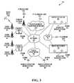
- FIG. 3depicts one exemplary radio dispatch system 10 in accordance with an embodiment of the present invention.
- the radio dispatch system 10comprises an IP network 20 , radio sites 30 coupled to radio systems 40 , dispatch centers 50 that include operator workstations 60 , PSTN 70 , a public IP network 80 , remote operator workstations 90 , a radio unit 100 , a telephony unit 110 , which can be a wireline or a wireless unit, an IP radio system 120 , an IP radio unit 130 , a packet-based IP telephone network 140 , and an IP telephony unit 150 .
- Distributed call management modules 35are provided in the radio sites 30
- distributed call management modules 55are provided in dispatch centers 50
- distributed call management modules 95are provided in remote operator workstations 90 .
- the distributed call management modules 35 , 55 , 95provide distributed dispatch call processing functionality as described herein.
- the IP network 20is an ATM (Asynchronous Transfer Mode) network.
- the IP network 20is a Frame Relay Network.
- the radio systems 40are land mobile radio systems.
- the public IP network 80is the Internet.
- FIG. 3shows a very specific example implementation of an embodiment of the invention.
- Other embodimentscomprise any combination of audio devices and distributed call management modules connected to an IP network.
- FIG. 3shows two radio sites 30 connected to the IP network 20 .
- any number of radio sitescan be connected to the IP network.
- Distributed call management modules 35are shown in the radio sites 30 .
- the distributed call management modulesare not co-located with the radio site.
- the distributed call management modules 35can be located between the radio site and the IP network.
- FIG. 3shows two radio systems 40 for each radio site 30 .
- any number of radio systems 40can be connected to each radio site 30 .
- FIG. 3shows one radio unit 100 in communication with a radio system 40 .
- FIG. 3also shows one IP radio unit 130 and one IP radio system 120 . It is understood that any number of IP radio units 130 and IP radio systems 120 are possible in other embodiments. Only one IP telephony unit 150 and one packet-based IP telephone network 140 are shown. In other embodiments, any number of IP telephony units 150 and packet-based IP telephone networks 140 are possible. As well, each packet-based IP telephone network 140 may be linked to a plurality of IP telephony units 150 .
- Two dispatch centers 50are shown in FIG. 3 . Any number of dispatch centers 50 is possible in other embodiments. Each dispatch center 50 shown in FIG. 3 has two operator workstations 60 and one distributed call management module 55 .
- the dispatch centers 50can have any number of operator workstations 60 and distributed call management modules 55 . Furthermore, distributed call management modules 55 can be located outside the dispatch centers 50 .
- FIG. 3also shows only one telephony unit 110 connected to PSTN 70 . Any number of telephony units 110 can be connected to the PSTN 70 . Likewise, any number of PSTN's can exist.
- the PSTN 70is shown connected to two dispatch centers 50 .
- the PSTNcan be connected to the IP network through any number of dispatch centers or through a distributed call management module located exterior to a dispatch center.
- FIG. 3shows two remote operator workstations 90 and one public IP network 80 . Any number of remote operator workstations 90 and any number of public IP networks 80 are possible.
- the remote operator workstations 90are shown having distributed call management modules 95 located on the workstations 90 .
- Distributed call management modules 95can be located exterior to the remote operator workstations 90 .
- the systemmay also include a system manager capable of system maintenance, administration and configuration.
- the systemis partitioned so that any one audio source has access to only a defined subset of system resources.
- the operators of the workstations 60 or 90are monitoring all traffic from a number of radio channels.
- each operatorsubscribes to the IP multicast group of each channel it needs to monitor.
- FIG. 3shows radio calls from radio units that are IP radio units and/or non-IP radio units. Some embodiments include only non-IP radio units. Other embodiments include only IP radio units. The capability to handle remote workstations connected to the public IP network is included in the FIG. 3 embodiments. Other embodiments include only stationary workstations. Still other embodiments include only remote workstations.
- the telephony interfaces, shown in FIG. 3are both PSTN and IP-based. Some embodiments have only PSTN telephony interfaces. Other embodiments have only IP-based telephony interfaces. Other embodiments have only radio interfaces and no telephony interfaces.
- a radio unit 100can initiate a radio call, which can be a voice transmission, a data transmission or any combination thereof.
- the callis routed via RF to radio system 40 , then through radio system 40 to a radio site 30 .
- the communication between the radio system 40 and the radio site 30is over a physical circuit.
- the distributed call management module 35 at the radio site 30converts the radio call to IP packets for transmission to and reception by entities connected to the IP network 20 , using a method to be described in detail later.
- the IP packetsare transmitted by IP multicast or a similar mechanism that results in each packet being forwarded to multiple destinations simultaneously.
- the distributed call management modules of the audio devices that have subscribed to the multicast addresswill receive the packets and can then subsequently monitor the radio call.
- each radio channelis monitored by a respective plurality of operator workstations.
- the call audiomight be directed to a headset or speaker and the call data can be displayed at such workstations.
- an operator of an operator workstation 60 or 90can initiate a radio call to a group of one or more radio units 100 , which can be a voice transmission, a data transmission or any combination thereof.
- the transmissionis converted to IP packets and the IP packets are sent over the IP network using IP multicast or a similar mechanism to the one or more radio units.
- the IP packetsare routed by distributed call management module 55 or 95 through the IP network 20 to one or more radio sites 30 , where distributed call management modules 35 convert them to audio and data signals.
- the audio and data signalsare then directed by the distributed call management modules 35 to the radio system 40 for broadcasting over the RF network and receiving by radio units 100 .
- a telephone unit 110can initiate a telephone call. As shown in the FIG. 3 embodiment, such call is routed through the PSTN 70 to the dispatch centers 50 , where it is routed through distributed call management module 55 .
- the routing from the telephone unit 110 to the PSTN 70can include the use of physical circuits.
- the dispatch centers 50determine the proper operator workstation 60 or 90 to which to present the call, based on call distribution rules preset in accordance with the mandates of the dispatch system. The operator workstation 60 or 90 can then be used to answer the call. Similarly, an operator workstation 60 or 90 can place a call to a telephone unit 110 through distributed call management module and the PSTN 70 .
- a radio unit 130 on an IP radio system 120can initiate a radio call to a group of operators, which can be a voice transmission, a data transmission or any combination thereof. Such a call can be routed via RF to radio system 120 , then through to a radio site 30 , where the communication between the IP radio system 120 and the radio site 30 is over the IP network.
- the distributed call management module 35 at radio site 30converts packets received from IP radio system 120 to multicast packets and relays the IP packets from radio system 120 for processing by entities connected to the IP network 20 , using a method to be described in detail later.
- This architectureallows the radio site 30 to operate with not only legacy systems such as radio systems 40 , but also IP radio systems 120 , in which case instead of the hard-wired connection as between the radio system 40 and the radio site 30 , there is a virtual connection via the IP network 20 between the IP radio system 120 and the radio site 30 . Any operator using an operator workstation 60 or 90 receiving the packets can then subsequently monitor the radio call.
- an operator workstation 60can initiate a radio call to IP radio unit 130 , which can be a voice transmission, a data transmission or any combination thereof.
- IP radio unit 130can be a voice transmission, a data transmission or any combination thereof.
- Such a callcan be routed through distributed call management module 55 to the IP network 20 to a distributed call management module 35 at a radio site 30 to an IP radio system 120 .
- the operator voiceis then directed to the radio system 120 for broadcasting over the RF network and receiving by radio unit 130 .
- an IP telephony unit 150can initiate a telephone call. Such a call can be routed through the IP telephone network 140 to the dispatch centers 50 , using the IP network 20 .
- the distributed call management modules 55 at dispatch centers 50determine the proper workstation 60 or 90 to which to present the call, based on preset call distribution rules. The workstation 60 or 90 can then be used to answer the call.
- an operator workstation 60 or 90can select a telephone line on which to place a call to an IP telephone unit 150 through IP telephone network 140 .
- An intercom callis a call between operators that does not go through telephone lines;
- Any combination of operator workstationscan be connected together with any combination of telephone lines to form a telephone conference;
- Any combination of telephone linescan be connected together to form an unattended telephone conference
- radio channelscan be connected towards any combination of operator workstations for the purpose of monitoring or listening in to radio channels;
- Any operator workstationcan be connected towards any combination of radio channels for the purpose of transmitting over radio channels;
- radio channelscan be connected together in a radio patch
- Any combination of radio channels and any combination of telephone linescan be connected together in a telephone/radio patch.
- the distributed call management module responsible for the workstationsubscribes to the IP multicast group for the PSTN line, and converts the IP packets to audio for the operator headset or speaker.
- the distributed call management module responsible for the PSTN linesubscribes to the IP multicast group for the operator workstation, and converts the IP packets to audio for transmitting towards the PSTN line.
- all audio exchange between the two distributed call management modulesis in the form of IP packets to two IP multicast group addresses, with half of the conversation carried by each IP multicast group address.
- a second operator monitoring the status group addressmay decide to join in the conversation.
- the first operatormay invite the second operator to join.
- the distributed call management module responsible for the second operator workstationsubscribes to the IP multicast group of the first operator workstation and the IP multicast group of the PSTN line, and combines the packets by audio summation techniques for transmission towards the second operator's headset or speaker.
- the distributed call management module responsible for the first operator workstationsubscribes to the IP multicast group for the second operator workstation and sums the second operator workstation's audio with the PSTN line audio towards the first operator's headset or speaker
- the distributed call management module responsible for the PSTN linesubscribes to the multicast group for the second operator workstation and sums the second operator workstation's audio with the first operator workstation's audio towards the PSTN line.
- the signal chart of FIG. 4shows an example of signaling to initiate the three way conference of the last example. For the purpose of this example, only the audio signals are discussed. In some embodiments status signals and status IP packets are also sent and received.
- FIG. 4shows signals being sent and received by a PSTN line 790 , a distributed call management module 792 responsible for the PSTN line 790 , an operator workstation 796 , a distributed call management module 794 responsible for the operator workstation 796 , another operator workstation 780 and a distributed call management module 798 responsible for the operator workstation 780 .
- an audio signal 761 from the first operator workstation 796 to the PSTN line 790is sent through the distributed call management module 794 , which converts the audio to IP packets.
- the distributed call management module 794sends the IP packets 763 over operator workstation 796 's IP multicast group address.
- the distributed call management module 792converts the IP packets to an audio signal and sends the audio signal 764 to the PSTN line 790 .
- Audio 765 from the PSTN line 790is sent back through the distributed call management module 792 , where it is converted to IP packets 767 .
- the distributed call management module 792sends a subscription signal 766 for the IP multicast group of the first operator workstation 796 and transmits the IP packets 767 to the IP multicast address of the PSTN line 790 .
- the distributed call management module 794 responsible for the first operator workstation 796receives the IP packets 767 , converts them to an audio signal 768 and sends the audio signal 768 to the first operator workstation 796 .
- a request signal 769is sent through the distributed call management module 798 , which then sends a subscription signal 770 for the IP multicast group of the PSTN line 790 and a subscription signal 771 for the IP multicast group of the first operator workstation 796 .
- the distributed call management modules 792 , 794then subscribe 772 , 773 to the IP multicast group of the second operator workstation 780 .
- audio 774 from the second operator workstation 780is converted to IP packets 775 , 776 and sent to the second operator workstation 780 's IP multicast group address.
- IP packets 775 and 776are sent as a single packet using multicast techniques.
- the IP packets 775are received by distributed call management module 792 and converted to audio signal 777 and sent to PSTN line 790 .
- the IP packets 776are received by distributed call management module 794 and are converted to audio signals 778 and sent to the first operator workstation 796 .
- audio from each of the three participantsis broadcast to the other two participants, thus creating a three-way conference call.
- Any one of the operator workstation s or the PSTN linecan unsubscribe from the IP multicast groups of the other two participants at any time and the conversation between the other two participants can continue.
- Another implementation of the present inventionis a method of dispatching a call in a dispatch system, such as a 911 dispatch system.
- a 911 dispatch systemeach operator is responsible for monitoring a number of RF channels.
- each channelhas its own IP multicast group address.
- the present inventionis not limited to RF channels. Any audio device with an IP multicast group address can be monitored. Operators responsible for monitoring a particular channel subscribe to that channel's IP multicast group address. When an emergency call is received on one of the channels, each operator who has subscribed to that channel's IP multicast group will hear the call and can decide to respond or not.
- Audio/signaling for a callcomes in to distributed call management module Y from an audio device (Step 801 ).
- Distributed call management module Yconverts the audio/signaling to IP packets (Step 802 ).
- Distributed call management module Ythen transmits the IP packets to the IP multicast group associated with the audio device (Step 803 ).
- the distributed call management modules responsible for the operator workstations in the audio device's IP multicast groupconvert the IP packets to a format understandable by their respective operator workstations (Step 804 ). The operator workstations can then receive the audio.
- Some operator workstationsaccept the call (Step 805 ). The acceptances go back through the distributed call management modules responsible for each operator workstation to the distributed call management module Y. In the event multiple acceptances are received, distributed call management module Y selects one operator workstation to take the call (Step 806 ). The distributed call management module responsible for channel Y then sends a channel access grant to the selected operator workstation (Step 807 ). In some embodiments, channel access denials are sent to the other operator workstations that accepted the call. The grant and denials are processed by each operator workstation, and in some embodiments an appropriate indicator is generated in the form of an audio or visual signal. The selected operator workstation is now free to transmit over the channel.
- the distributed call management module responsible for the selected operator workstationsubscribes to the IP multicast groups of the other channels and sends the IP packets to all of the distributed call management modules responsible for the channels that the selected operator workstation chose.
- priorities for callers on a channelare set by an administrative interface.
- the distributed call management module responsible for a channelcan do arbitration according to preset rules to determine which caller is granted access. In some cases, a caller with a higher priority can preempt a caller who is already using the channel. In some embodiments, the distributed call management module responsible for the channel can conduct this preemption function.
- FIG. 6is a signal chart for an example 911 call dispatch.
- FIG. 6shows signals being sent and received by channel 850 , distributed call management module 852 , distributed call management module 854 , operator workstation 856 , distributed call management module 858 , operator workstation 860 , distributed call management module 862 and operator workstation 864 .
- Distributed call management module 862is the distributed call management module responsible for operator workstation 864 .
- Distributed call management module 858is the distributed call management module responsible for operator workstation 860 .
- Distributed call management module 854is the distributed call management module responsible for operator workstation 856 .
- Distributed call management module 852is the distributed call management module responsible for channel 850 .
- the three operator workstations 856 , 860 and 864have subscribed to the IP multicast group associated with channel 850 .
- the call 820comes in on the channel 850 to distributed call management module 852 .
- Distributed call management module 852converts the audio and signaling of the call to IP packets and sends the IP packets 821 , 822 , 823 to the IP multicast group of the channel 850 .
- IP packets 821 , 822 , and 823are sent as a single packet using multicast techniques.
- Distributed call management modules 854 , 858 , and 862receive the IP packets and convert them to audio and signaling.
- the distributed call management modules 854 , 858 , and 862send the converted signals 824 , 825 , 826 to their respective operator workstations 856 , 860 and 864 .
- Operators 856 and 860are shown sending acceptance signals 827 , 829 to distributed call management modules 854 and 858 respectively.
- Operator workstation 864is shown sending a rejection signal 831 to distributed call management module 862 rejecting the call.
- Distributed call management modules 854 and 858convert the acceptances and send them to distributed call management module 852 as IP packets 828 and 830 , respectively.
- Distributed call management module 862converts the rejection signal to IP packets 832 and sends the IP packets 832 to distributed call management module 852 .
- Distributed call management module 852then chooses an operator workstation to take the call 833 .
- operator workstation 856is chosen as the operator workstation to take the call.
- a channel access grant signal 834is sent to distributed call management module 854 along with a subscription to operator workstation 856 's IP multicast group.
- Distributed call management module 854converts the signal and sends the converted signal 835 to operator workstation 856 .
- a channel access denial signal 836is sent to distributed call management module 858 , where it is converted.
- the converted denial 837is sent to operator workstation 860 .
- Operator workstation 856then commences transmitting an audio signal 838 .
- the audio signal 838goes to distributed call management module 854 , where it is converted to IP packets 839 and sent to distributed call management module 852 .
- Distributed call management module 852converts the IP packets 839 to an audio signal 840 and sends the audio signal 840 over channel 850 .
- each operator workstationis monitoring a number of channels.
- An operator workstationcan also transmit on the channels which the operator workstation is monitoring.
- the operator workstationmakes a request to each channel, indicating at the same time the operator workstation's IP multicast group address.
- each channelsubscribes to the operator workstation's IP multicast group and transmission can begin at the same time.
- the acceptance signalis tied to a Push-to-talk switch, in which case arbitration takes place on a transaction by transaction basis. In other words, there is no arbitration for the entire call.
- FIGS. 7 and 8show distributed call management modules located in a radio site and a dispatch center. Of course, distributed call management modules can be located in many other locations.
- FIG. 7depicts one exemplary radio site in accordance with the present invention.
- a radio site 31comprises a plurality of radio distributed call management modules 160 , redundant IP switches 170 , and redundant IP routers 180 .
- Radio distributed call management modules 160are distributed call management modules designed to interface between a radio system and an IP network.
- the radio site 31communicates with the radio stations 190 in the radio system 41 via radio interfaces 200 .
- the radio distributed call management modules 160communicate with the IP switches 170 via LAN connections 210 .
- the LAN connections 210are Ethernet connections.
- the IP switches 170communicate with the IP routers 180 via redundant LAN connections 220 .
- the IP routers 180communicate with the IP network 20 via redundant WAN connections 230 .
- the WAN connections 230can be ATM or Frame Relay links over copper, optical or wireless connections.
- a radio callarrives at the radio site 30 over a radio interface 200 , it is processed by a radio distributed call management module 160 .
- the radio distributed call management module 160interprets the signaling of the radio call and converts the call status data to an IP packet and multicasts the IP packet to all distributed call management modules of the system using a status multicast group.
- the status multicast groupis an IP multicast group that is subscribed to by all distributed call management modules and is used to multicast status changes.
- the radio distributed call management module 160also converts the audio to RTP (Real-time Transport Protocol) and sends it over the designated IP multicast group for the particular radio channel.
- RTPReal-time Transport Protocol
- the call signalingis radio system specific and can include combinations of “talk and listen” signaling such as call indication, advanced conventional signaling such as unit ID, emergency, and trunked system signaling such as individual call or unit status.
- “talk and listen” signalingsuch as call indication
- advanced conventional signalingsuch as unit ID, emergency, and trunked system signaling
- trunked system signalingsuch as individual call or unit status.
- status conversion in the illustrative distributed systemstatus changes as a result of received signaling are multicast to all distributed call management modules for the distributed call management modules to update their local status database and subsequent presentation to an operator workstation.
- Radio distributed call management modules 160can also provide radio calls over a radio interface 200 , at the request of an operator workstation within the system or for a non-operator-initiated transmission, such as a patch or radio repeat transmission.
- the signalingcan be originated by the radio distributed call management module 160 towards the radio interface 200 , and the audio can be taken from its RTP form on an IP multicast group address and converted for transmission towards the radio interface 200 .
- the IP switches 170serve as packet switches for the radio site 30 , by directing packets coming over the LAN connections 210 and 220 from the radio distributed call management modules 160 and routers 180 to the destinations over the LAN connections 210 and 220 .
- a radio distributed call management module 160could send an IP packet to a specific IP multicast group address, in which case an IP switch 170 would receive the IP packet on a LAN connection 210 and forward it on all LAN connections 210 and 220 that subscribe to the IP multicast group.
- the WAN routers 180serve to bridge the radio site LAN with the IP network 20 . To this end, they can perform translation from the LAN protocol to the IP network protocol, as well as NAT (Network Address Translation) and firewall functions as appropriate.
- NATNetwork Address Translation
- FIG. 8depicts one exemplary dispatch center 51 in accordance with the present invention.
- Dispatch center 51preferably comprises redundant IP routers 240 , redundant IP switches 250 , a plurality of operator distributed call management modules 260 serving operator workstations 60 , a plurality of telephone distributed call management modules 270 operatively coupled via telephone lines 290 to an end office 280 that is in the PSTN 70 .
- Operator distributed call management modules 260are distributed call management modules that interface between operator workstations 60 and an IP network 20 .
- Telephone distributed call management modules 270are distributed call management modules that interface between a PSTN 70 and an IP network 20 .
- the IP routers 240 and IP switches 250preferably communicate via redundant LAN connections 300 .
- the IP switches 250 , operator distributed call management modules 260 and telephone distributed call management modules 270preferably communicate via LAN connections 310 .
- the IP routers 240communicate with the IP network 20 via redundant WAN connections 320 .
- the WAN connections 320are ATM or Frame Relay links over copper or optical connections.
- the IP switches 250serve as the packet switches for the dispatch center 51 , by directing packets coming over the LAN connections 300 and 310 from the WAN routers 240 , telephone distributed call management modules 270 and operator distributed call management modules 260 to the destinations over the LAN connections 300 and 310 .
- a telephone distributed call management module 270could send an IP multicast packet to a specific IP multicast group address, in which case an IP switch 250 would receive the packet on a LAN connection 310 and forward it on all LAN connections 300 and 310 that subscribe to this IP multicast group.
- the telephone distributed call management modules 270terminate telephone lines 290 originating from the PSTN 70 . These lines carry incoming and outgoing telephone traffic.
- the operator distributed call management modules 260provide the network termination and call processing for the operator workstations 60 .
- Operator workstations 60can be used to receive and originate radio calls, telephone calls, and intercom calls.
- the distributed call management module shown in FIG. 9performs all three functions.
- FIG. 9depicts one exemplary distributed call management module 320 in accordance with the present invention.
- Distributed call management module 320comprises a call processing and management engine 330 , an audio processing engine 340 , a packet processor 350 coupled to an IP network 390 over a LAN connection 400 , a radio gateway 360 coupled to a radio system 410 over radio interfaces 420 , a telephone gateway 370 coupled to the PSTN 430 over telephone lines 440 , an operator workstation gateway 380 coupled to operator workstation 450 over the operator interface 460 .
- LAN connection 400is an Ethernet connection.
- signaling links 470couple the gateways 360 , 370 , 380 , and the call processing and management engine 330 ; audio links 480 couple the gateways 360 , 370 , 380 , and the audio processing engine 340 ; control link 500 couples the call processing and management engine 330 with the audio processing engine 440 ; data links 510 and 520 couple the call processing and management engine 330 , the audio management engine 340 , and the packet processor 350 .
- the radio gateway 360provides a plurality of radio interfaces 420 to radio systems 410 .
- One of the roles of the radio gateway 360is to implement the radio interface 420 , which is dependent on the radio system 410 .
- the gatewayhas the hardware and software to convert the signaling and audio into and from packet form.
- the radio gateway 360can terminate and originate the signaling required to control the radio system 410 , and can provide an interface to the call processing and management engine 330 for the control, over, for example, the interface 470 .
- the radio gateway 360can also convert the audio from the radio system 410 over the radio interface 420 to a form meaningful for exchange with the audio processing engine 340 over the link 480 .
- the radio gateway 360also does the reverse conversion of signals from the audio processing engine into audio in a form meaningful to the radio system 410 . Details as the configuration of a radio gateway can be found in the Applicant's co-pending U.S. patent application Ser. No. 11/095,465 “Radio Gateway System and Method for Interfacing a Radio System and an IP network”.
- the telephone gateway 370provides a plurality of telephone interfaces 440 to PSTN 430 .
- One of the roles of the telephone gateway 370is to implement the telephone interface 440 , which is dependent on the PSTN 430 .
- the telephone gateway 370can terminate and originate the signaling required to control the PSTN 430 , and can provide an interface to the call processing and management engine 330 for the control, over the interface 470 .
- the telephone gateway 370can also convert the audio from the PSTN 430 over the telephone interface 440 to a form meaningful for exchange with the audio processing engine 340 over the link 480 .
- the telephone gateway 370also does the reverse conversion of signals from the audio processing engine into audio in a form meaningful to the PSTN 430 .
- the workstation gateway 380provides a plurality of workstation interfaces 460 to workstation 450 .
- One of the roles of the workstation gateway 380is to implement the workstation interface 460 , which is dependent on the workstation 450 .
- the workstation gateway 380can terminate and originate the signaling required to control the workstation 450 , and can provide an interface to the call processing and management engine 330 for said control, over the interface 470 .
- the workstation gateway 380can also convert the audio from the workstation 450 over the workstation interface 460 to a form meaningful for exchange with the audio processing engine 340 over the link 480 .
- the workstation gateway 380also does the reverse conversion of signals from the audio processing engine into audio in a form meaningful to the workstation 460 .
- the call processing and management engine 330performs similar functions to the call processing and management engine 710 described with reference to FIG. 2 .
- the audio processing engine 340performs functions similar to the audio processing engine 720 described with reference to FIG. 2 .
- the packet processor 350performs functions similar to the packet processor 730 described with reference to FIG. 2 .
- the radio gateway 360 , telephone gateway 370 , operator gateway 380 , call processing and management engine 330 , audio management engine 340 and packet processor 350could all reside within a single unit, with the operator workstation 450 residing in a separate physical unit (e.g. personal computer).
- the operator gateway 380 , call processing and management engine 330 , audio management engine 340 , packet processor 350 and operator workstation 450could reside within a single physical unit (e.g. personal computer), with the radio gateway and telephone gateway being separate physical units.
- the dispatch systemis not limited to the embodiments shown in FIGS. 1 and 3 .
- Other embodimentsare possible, due to the nature of multicast-enabled IP networks.
- FIG. 10depicts another exemplary dispatch system 530 in accordance with the present invention.
- the FIG. 10 systempreferably comprises an IP network 20 , a combined dispatch/radio site 540 that includes workstations 565 , a radio system 40 , a radio unit 100 , a PSTN 70 , a telephone unit 110 , a public IP network 80 , a packet-based IP telephone network 140 , an IP telephony unit 150 , two remote dispatch sites 550 and 560 that include combined distributed call management module/workstations 580 , and a mobile dispatch site 570 that includes a mobile workstation 590 .
- IP network 20preferably comprises an IP network 20 , a combined dispatch/radio site 540 that includes workstations 565 , a radio system 40 , a radio unit 100 , a PSTN 70 , a telephone unit 110 , a public IP network 80 , a packet-based IP telephone network 140 , an IP telephony unit 150 , two remote dispatch sites 550 and 560
- the IP network 20is a WAN and the public IP network 80 is the Internet.
- the telephone units 110are wireline units. In other embodiments they are wireless units. In still other embodiments they can include both wireless and wireline units.
- callscan be originated by any of the audio devices in the system of FIG. 10 .
- the callsare converted by distributed call management modules responsible for the audio devices according to a method described above and sent as IP packets to an IP multicast group address for the audio device that originated the call.
- the followingare examples of how calls are routed in the embodiment illustrated in FIG. 10 .
- a radio unit 100can initiate a radio call, which can be a voice transmission, a data transmission or any combination thereof, in which case the call is routed via RF to radio system 40 , then through radio system 40 to the combined dispatch/radio site 540 .
- Communication between the radio system 40 and the radio site 540can be over a physical circuit.
- a distributed call management module at the combined dispatch/radio site 540can convert the radio call to IP packets for processing by entities connected to the IP network 20 , using a method such as described earlier. Any workstation 565 , 580 or 590 that has subscribed to the IP multicast group of radio unit 100 is subsequently able to monitor the radio call.
- Any workstation 565 , 580 or 590can initiate a radio call to a radio unit 100 , which can be a voice transmission, a data transmission or any combination thereof, in which case the call is routed through the combined dispatch/radio site 540 to a radio system 40 .
- the communication between the combined dispatch/radio site 540 and the radio system 40can be over a physical circuit.
- the operator voiceis then directed to the radio system 40 for broadcasting over the RF network and receiving by radio unit 100 .
- a telephone unit 110can initiate a telephone call, which is routed through the PSTN 70 to the radio/dispatch site 540 , using, for example, common physical circuits.
- the distributed call management module at radio/dispatch site 540can convert the telephone call to IP packets for processing by entities connected to the IP network 20 , and determines the proper workstation 565 , 580 or 590 to which to present the call, based on preset call distribution rules.
- the workstation 565 , 580 or 590can then be used to answer the call.
- an operator workstation 565 , 580 or 590can select a telephone line to place a call to a telephone unit 110 through PSTN 70 .
- a IP telephony unit 150can initiate a telephone call, which is routed through the IP telephone network 140 to the radio/dispatch site 540 , using virtual circuits.
- the distributed call management module at radio/dispatch site 540determines the proper workstation 565 , 580 or 590 to which to present the call, based on preset call distribution rules.
- the workstation 565 , 580 or 590can then be used to answer the call.
- an operator workstation 565 , 580 or 590can select a telephone line to use to place a call to a IP telephone unit 150 through IP telephone network 140 .
- FIG. 11depicts one example of an embodiment of the dispatch system structure shown in FIG. 10 .
- the radio/dispatch site 540includes redundant IP switches 175 , redundant IP routers 185 , combined operator/radio/telephone distributed call management modules 600 , and workstations 565 .
- the radio/dispatch site 540couples the end offices 280 in the PSTN 70 via telephone lines 290 , couples the radio base stations 190 in the radio system 40 via radio interfaces 200 , and couples the IP telephone network 140 via the IP network 20 .
- the IP switches 175 and IP routers 85are coupled via redundant LAN connections 220 . In some embodiments the LAN connections are Ethernet connections.
- the IP switches 175 and distributed call management modules 600are coupled via LAN connections 210 .
- the IP routers 185are coupled to the IP network 20 via redundant WAN connections 230 , which in some embodiments are ATM or Frame Relay links over copper or optical connections.
- the workstations 565are coupled to the distributed call management modules 600 over links 610 . In some embodiments these links are physical links. In other embodiments they are virtual links where workstations 565 are coupled to the IP switches 175 and the connection between the workstations 565 and the distributed call management modules 600 is through the IP switches 175 .
- Remote dispatch site 550includes redundant IP routers 245 , redundant IP switches 255 , and workstations 580 .
- the workstations 580comprise combined operator distributed call management modules and workstations as described earlier.
- the IP routers 245 and IP switches 255are coupled via redundant LAN connections 305 .
- the IP switches 255 and workstations 585are coupled via LAN connections 315 .
- the IP routers 245are coupled to the IP network 20 via redundant WAN connections 325 .
- Remote dispatch site 560includes network access device 620 and workstation 580 .
- network devices 620include DSL or cable modems.
- Network access device 620 and workstation 580can be coupled via LAN connection 630 .
- the network access device 620can be coupled to the IP network 20 via WAN connection 640 , using, for example, a virtual network tunneled via the public IP network 80 .
- the WAN connection 640is a DSL connection. In other embodiments it is a cable connection.
- Remote dispatch site 570includes mobile workstation 590 , comprising an integrated network access device.
- the mobile workstation 590is a laptop computer and the network access device is a dial-up modem.
- Mobile workstation 590can comprise a combined operator distributed call management module and workstation as described earlier or it may be served by a distributed call management module 600 in radio/dispatch site 540 .
- the mobile workstation 590is coupled to the wide-area network 20 via WAN connection 640 , using, for example, a virtual network tunneled via the public IP network 80 .
- a radio callarrives from the radio site 40 over a radio interface 200 , it is processed by the combined operator/radio/telephone distributed call management module 600 , where the signaling is interpreted and converted to status changes multicast to all distributed call management modules over the status multicast group, and where the audio is converted to RTP and sent over the designated IP multicast group for the particular radio channel.
- operator/radio/telephone distributed call management modules 600can also originate radio calls over a radio interface 200 , at the request of an operator within the system or for a non-operator-initiated transmission, which in some embodiments is a patch or radio repeat transmission.
- the signalingis originated by the radio distributed call management module 600 towards the radio interface 200 , and the audio is taken from its RTP form on an IP multicast group and converted for transmission towards the radio interface 200 .
- the distributed call management modules 600also terminate telephone lines 290 originating from the PSTN 70 . These lines can carry incoming and outgoing telephone traffic.
- the distributed call management modules 600further provide the network termination and call processing for the operator workstations 565 . Operator workstations 565 can be used to receive and originate radio calls, telephone calls, and intercom calls.
- the IP switches 175serve a similar function to the IP switches 170 in FIG. 7 .
- the IP switches 255serve a similar function to the IP switches 250 in FIG. 8 .
- the routers 185serve a similar function to the routers 180 shown in FIG. 7 . To this end, they can perform translation from the LAN protocol, such as Ethernet to a WAN protocol, such as ATM or Frame Relay, as well as Network Address Translation (NAT) and firewall functions as appropriate.
- the routers 245serve a similar function to the routers 240 shown in FIG. 8 .
- the combined workstation/distributed call management modules 580can provide the network termination and call processing for the connected operator workstations, which can be used to receive and originate radio calls, telephone calls, and intercom calls.
- the network access device 620serves to bridge the distributed call management module/workstation 580 in remote dispatch site 560 to the network 20 . To this end, it can perform translation from the workstation protocol, such as Ethernet to a WAN protocol, such as DSL or cable. For remote dispatch site 560 , as well as for the remote PSAP 570 case, Network Address Translation (NAT) and firewall functions can be performed by the workstation 580 or 590 .
- NATNetwork Address Translation
Landscapes
- Engineering & Computer Science (AREA)
- Signal Processing (AREA)
- Computer Networks & Wireless Communication (AREA)
- Telephonic Communication Services (AREA)
- Data Exchanges In Wide-Area Networks (AREA)
Abstract
Description
Claims (50)
Priority Applications (5)
| Application Number | Priority Date | Filing Date | Title |
|---|---|---|---|
| US11/096,081US7483416B2 (en) | 2005-04-01 | 2005-04-01 | Internet protocol radio dispatch system and method |
| EP06740141.4AEP1875756B1 (en) | 2005-04-01 | 2006-03-29 | Internet protocol radio dispatch system and method |
| PCT/US2006/011817WO2006107732A1 (en) | 2005-04-01 | 2006-03-29 | Internet protocol radio dispatch system and method |
| US12/340,385US8194647B2 (en) | 2005-04-01 | 2008-12-19 | Internet protocol radio dispatch system and method |
| US13/488,087US8761071B2 (en) | 2005-04-01 | 2012-06-04 | Internet protocol radio dispatch system and method |
Applications Claiming Priority (1)
| Application Number | Priority Date | Filing Date | Title |
|---|---|---|---|
| US11/096,081US7483416B2 (en) | 2005-04-01 | 2005-04-01 | Internet protocol radio dispatch system and method |
Related Child Applications (1)
| Application Number | Title | Priority Date | Filing Date |
|---|---|---|---|
| US12/340,385ContinuationUS8194647B2 (en) | 2005-04-01 | 2008-12-19 | Internet protocol radio dispatch system and method |
Publications (2)
| Publication Number | Publication Date |
|---|---|
| US20060221937A1 US20060221937A1 (en) | 2006-10-05 |
| US7483416B2true US7483416B2 (en) | 2009-01-27 |
Family
ID=36676029
Family Applications (3)
| Application Number | Title | Priority Date | Filing Date |
|---|---|---|---|
| US11/096,081Active2027-01-23US7483416B2 (en) | 2005-04-01 | 2005-04-01 | Internet protocol radio dispatch system and method |
| US12/340,385Active2027-01-27US8194647B2 (en) | 2005-04-01 | 2008-12-19 | Internet protocol radio dispatch system and method |
| US13/488,087Expired - LifetimeUS8761071B2 (en) | 2005-04-01 | 2012-06-04 | Internet protocol radio dispatch system and method |
Family Applications After (2)
| Application Number | Title | Priority Date | Filing Date |
|---|---|---|---|
| US12/340,385Active2027-01-27US8194647B2 (en) | 2005-04-01 | 2008-12-19 | Internet protocol radio dispatch system and method |
| US13/488,087Expired - LifetimeUS8761071B2 (en) | 2005-04-01 | 2012-06-04 | Internet protocol radio dispatch system and method |
Country Status (3)
| Country | Link |
|---|---|
| US (3) | US7483416B2 (en) |
| EP (1) | EP1875756B1 (en) |
| WO (1) | WO2006107732A1 (en) |
Cited By (9)
| Publication number | Priority date | Publication date | Assignee | Title |
|---|---|---|---|---|
| US20060262800A1 (en)* | 2005-05-17 | 2006-11-23 | Martinez Dennis M | Multimode land mobile radio |
| US20070121593A1 (en)* | 2005-06-10 | 2007-05-31 | Vance William H | Method and apparatus for ensuring accessibility to emergency service via VoIP or via PSTN |
| US20080031207A1 (en)* | 2006-08-07 | 2008-02-07 | M/A-Com, Inc. | Multiple protocol land mobile radio system |
| US20080299940A1 (en)* | 2007-06-01 | 2008-12-04 | Cisco Technology, Inc. | Interoperability and collaboration system with emergency interception monitoring |
| US20100232355A1 (en)* | 2009-03-13 | 2010-09-16 | Harris Corporation | Asymmetric broadband data network |
| US8279868B2 (en) | 2005-05-17 | 2012-10-02 | Pine Valley Investments, Inc. | System providing land mobile radio content using a cellular data network |
| US20120265867A1 (en)* | 2005-07-18 | 2012-10-18 | Joseph Boucher | Dynamic Asset Marshalling Within an Incident communications Network |
| US9654200B2 (en) | 2005-07-18 | 2017-05-16 | Mutualink, Inc. | System and method for dynamic wireless aerial mesh network |
| US9871767B2 (en) | 2005-07-18 | 2018-01-16 | Mutualink, Inc. | Enabling ad hoc trusted connections among enclaved communication communities |
Families Citing this family (21)
| Publication number | Priority date | Publication date | Assignee | Title |
|---|---|---|---|---|
| AU6120900A (en)* | 1999-06-08 | 2000-12-28 | Trustees Of Columbia University In The City Of New York, The | Network telephony appliance and system for inter/intranet telephony |
| WO2008005046A1 (en)* | 2006-06-30 | 2008-01-10 | Sony Ericsson Mobile Communications Ab | Portable communication device and method for simultaneously handling circuit-switched and packet-switched audio |
| US8249068B2 (en) | 2006-10-20 | 2012-08-21 | Alcatel Lucent | Method and apparatus for establishing multicast groups |
| US20080159274A1 (en)* | 2006-12-29 | 2008-07-03 | Brugman David L | Method and apparatus for improved routing necessitated by network element replacement |
| US20080159273A1 (en)* | 2006-12-29 | 2008-07-03 | Brugman David L | Method and apparatus for facilitating migration from an analog network to a voice over internet protocol network |
| US20080159504A1 (en)* | 2006-12-29 | 2008-07-03 | Brugman David L | Method and apparatus for improved analog line migration to accommodate customer premise equipment changes |
| US7839811B2 (en)* | 2007-02-27 | 2010-11-23 | Pine Valley Investments, Inc. | Radio frequency multicasting |
| US8149269B2 (en)* | 2007-04-10 | 2012-04-03 | West Corporation | Emergency services call delivery from a legacy communications device to a VoIP PSAP |
| US8897179B2 (en)* | 2010-08-30 | 2014-11-25 | Cisco Technology, Inc. | Method and apparatus for detecting an offline radio resource in an interoperability system |
| US8711837B1 (en) | 2010-09-29 | 2014-04-29 | Lockheed Martin Corporation | Methods, apparatus, and systems for facilitating control communications between disparate devices |
| US9252982B2 (en)* | 2010-10-21 | 2016-02-02 | Marshall Jobe | System and method for simulating a land mobile radio system |
| DE102012109060A1 (en)* | 2011-09-29 | 2013-04-04 | Sma Solar Technology Ag | Communication with decentralized, electrical energy handling facilities via the Internet |
| US9178893B2 (en) | 2012-04-11 | 2015-11-03 | Motorola Solutions, Inc. | Secure AD HOC communication systems and methods across heterogeneous systems |
| US20140050123A1 (en)* | 2012-08-17 | 2014-02-20 | Harris Corp | Communications system including voip bridge radio providing channel designation features and related methods |
| US9774386B2 (en) | 2013-03-15 | 2017-09-26 | E.F. Johnson Company | Distributed simulcast architecture |
| US9800460B2 (en) | 2014-08-01 | 2017-10-24 | E.F. Johnson Company | Interoperability gateway for land mobile radio system |
| AU2015215962B2 (en) | 2014-08-21 | 2019-11-21 | Tait International Limited | Integration of lmr and ip networks |
| US9763260B2 (en) | 2014-11-06 | 2017-09-12 | E.F. Johnson Company | System and method for dynamic channel allocaton |
| JP7139658B2 (en)* | 2018-03-30 | 2022-09-21 | ソニーグループ株式会社 | Information processing device, information processing method, and program |
| US20220182760A1 (en)* | 2020-12-04 | 2022-06-09 | Universal City Studios Llc | System and method for private audio channels |
| CN113270097B (en)* | 2021-05-18 | 2022-05-17 | 成都傅立叶电子科技有限公司 | Unmanned mechanical control method, radio station voice instruction conversion method and device |
Citations (78)
| Publication number | Priority date | Publication date | Assignee | Title |
|---|---|---|---|---|
| US3881060A (en) | 1973-06-04 | 1975-04-29 | Bell Telephone Labor Inc | Emergency reporting system |
| US4029901A (en) | 1975-11-13 | 1977-06-14 | Motorola, Inc. | Control center for a communications system with interchannel patching capabilities |
| US4677656A (en) | 1984-06-19 | 1987-06-30 | Motorola, Inc. | Telephone-radio interconnect system |
| US4893325A (en) | 1988-09-23 | 1990-01-09 | Rockwell International Corporation | Integrated public safety answering point system |
| US5206903A (en) | 1990-12-26 | 1993-04-27 | At&T Bell Laboratories | Automatic call distribution based on matching required skills with agents skills |
| US5239570A (en) | 1990-07-25 | 1993-08-24 | Teltone Corporation | 9-1-1 Switched access system |
| US5311569A (en) | 1992-06-05 | 1994-05-10 | At&T Bell Laboratories | Line-based public safety answering point |
| US5392277A (en) | 1993-06-11 | 1995-02-21 | At&T Corp. | Routing to intelligence |
| US5479482A (en) | 1993-08-30 | 1995-12-26 | At&T Corp. | Cellular terminal for providing public emergency call location information |
| US5481545A (en) | 1991-08-26 | 1996-01-02 | Ericsson Inc. | Conventional network interface for multisite RF trunking system |
| US5696809A (en) | 1995-06-22 | 1997-12-09 | Bell Atlantic Network Services, Inc. | Advanced intelligent network based computer architecture for concurrent delivery of voice and text data using failure management system |
| US5841848A (en) | 1996-05-07 | 1998-11-24 | Lucent Technologies Inc. | System and method for completing telephone calls to emergency telephone numbers in highly concentrated access systems |
| US5844974A (en) | 1995-05-22 | 1998-12-01 | Nec Corporation | Emergency telephone communications system |
| US5862485A (en) | 1995-03-31 | 1999-01-19 | Motorola, Inc. | Method and apparatus for allocating communication resources to support priority communications in a communication system |
| US5867562A (en) | 1996-04-17 | 1999-02-02 | Scherer; Gordon F. | Call processing system with call screening |
| US5898757A (en) | 1996-07-12 | 1999-04-27 | At&T Corp | Method and system for processing emergency service calls |
| US5905792A (en) | 1997-02-10 | 1999-05-18 | Genesys Telecommunications Laboratories, Inc. | External positivistic forward transfer in call routing systems |
| US5915010A (en) | 1996-06-10 | 1999-06-22 | Teknekron Infoswitch | System, method and user interface for data announced call transfer |
| US5937334A (en) | 1996-09-30 | 1999-08-10 | Fred Peterson | Radio communications and telephone network interface system |
| US5937051A (en) | 1993-07-08 | 1999-08-10 | Teknekron Infoswitch Corporation | Method and system for transferring calls and call-related data between a plurality of call centers |
| US5937355A (en) | 1995-12-07 | 1999-08-10 | Telefonaktiebolaget Lm Ericsson (Publ) | Emergency call handling in a cellular telecommunication system |
| US5940497A (en) | 1997-02-10 | 1999-08-17 | Genesys Telecommunications Laboratories, Inc. | Statistically-predictive and agent-predictive call routing |
| US5999965A (en) | 1996-08-20 | 1999-12-07 | Netspeak Corporation | Automatic call distribution server for computer telephony communications |
| US6009163A (en) | 1997-07-03 | 1999-12-28 | U S West, Inc. | Method and system for regulating incoming calls from multiple points of origination |
| US6067356A (en) | 1997-09-20 | 2000-05-23 | Alcatel | Method of routing emergency calls |
| US6075853A (en) | 1997-03-31 | 2000-06-13 | Sbc Technology Resources, Inc. | Apparatus and method for intelligent call routing and call return |
| US6128481A (en) | 1997-10-22 | 2000-10-03 | Telefonaktiebolaget L M Ericsson (Publ) | System and method of routing emergency services calls in a radio telecommunications network |
| CA2306638A1 (en) | 1999-04-04 | 2000-11-04 | Mitel Corporation | Multi-line telephone system emergency call processing |
| EP1054554A2 (en) | 1999-04-27 | 2000-11-22 | Citibank, N.A. | System and method for automated telephone message routing |
| US6175564B1 (en) | 1995-10-25 | 2001-01-16 | Genesys Telecommunications Laboratories, Inc | Apparatus and methods for managing multiple internet protocol capable call centers |
| US6175562B1 (en) | 1997-04-29 | 2001-01-16 | Intervoice Limited Partnership | Switchless call processing |
| US6185205B1 (en) | 1998-06-01 | 2001-02-06 | Motorola, Inc. | Method and apparatus for providing global communications interoperability |
| US6198920B1 (en) | 1995-06-01 | 2001-03-06 | Padcom, Inc. | Apparatus and method for intelligent routing of data between a remote device and a host system |
| US6233445B1 (en) | 1997-01-14 | 2001-05-15 | Ericsson, Inc. | Establishing emergency calls within a mobile telecommunications network |
| EP1109417A1 (en) | 1999-12-17 | 2001-06-20 | Nortel Networks Limited | System and method for unifying the implementation and processing mobile communications and a unified mobility manager for providing such communications |
| US6252943B1 (en) | 1999-11-03 | 2001-06-26 | At&T Corp | Telephone network having dual gateway interconnection architecture for handling emergency services |
| US6256489B1 (en) | 1997-04-24 | 2001-07-03 | Lucent Technologies Inc. | Enhanced emergency service for ISDN based emergency services in a wireless telecommunications system |
| WO2001065868A1 (en) | 2000-03-01 | 2001-09-07 | Motorola Inc. | Transmission within a wireless communication system |
| WO2001065763A2 (en) | 2000-02-29 | 2001-09-07 | 3Com Corporation | Providing location information for telephony over data communication networks |
| US6289083B1 (en) | 2000-02-16 | 2001-09-11 | Rockwell Electronic Commerce Corp. | Method of identifying a location of a source of an emergency call in a call center environment |
| WO2001067733A1 (en) | 2000-03-04 | 2001-09-13 | Lucent Technologies Inc. | System for providing expanded emergency service communication in a telecommunication network |
| US6292542B1 (en) | 1999-08-11 | 2001-09-18 | At&T Corp. | Method and apparatus for handling an in-call request for emergency services |
| US20010040887A1 (en) | 1997-10-09 | 2001-11-15 | Yuri Shtivelman | Apparatus and methods enhancing call routing to and within call-centers |
| US6324279B1 (en)* | 1998-08-04 | 2001-11-27 | At&T Corp. | Method for exchanging signaling messages in two phases |
| US6327342B1 (en) | 1999-05-28 | 2001-12-04 | Matthew Stephen Mobley | E911 backup system for emergency 911 call answering systems |
| US6330324B1 (en) | 1997-12-09 | 2001-12-11 | Sbc Technology Resources, Inc. | Geographical call routing for a non-emergency calling service |
| US6332022B1 (en) | 1997-12-22 | 2001-12-18 | Nortel Networks Limited | Method and apparatus for routing emergency services calls in an intelligent network |
| US20020001300A1 (en) | 1996-07-09 | 2002-01-03 | Alec Miloslavsky | Internet protocol call-in centers and establishing remote agents |
| US6392999B1 (en) | 1999-08-10 | 2002-05-21 | Lucent Technologies Inc. | Conferencing and announcement generation for wireless VoIP and VoATM calls |
| US20020068584A1 (en)* | 2000-12-05 | 2002-06-06 | Nortel Networks Limited | Method and system for transmitting data to a mobile device |
| US20020110104A1 (en) | 2001-02-13 | 2002-08-15 | Telefonaktiebolaget Lm Ericsson (Publ). | Hybrid media gateway control function providing circuit-switched access to a packet-switched radio telecommunications network |
| US6453038B1 (en) | 1998-06-03 | 2002-09-17 | Avaya Technology Corp. | System for integrating agent database access skills in call center agent assignment applications |
| US20020197977A1 (en) | 2001-06-25 | 2002-12-26 | Frank Brooks | Control and messaging during emergency calls |
| US20030007469A1 (en) | 2001-07-05 | 2003-01-09 | Daley Robert S. | System and method for voice over IP |
| US20030053434A1 (en) | 2001-08-03 | 2003-03-20 | At&T Corp. | Method and apparatus for delivering IPP2T (IP-push-to-talk) wireless LAN mobile radio service |
| US20030058827A1 (en) | 2001-08-03 | 2003-03-27 | At&T Corp. | Architecture and method for using IEEE 802.11-like wireless LAN system to emulate private land mobile radio system (PLMRS) radio service |
| US20030139174A1 (en) | 2001-12-13 | 2003-07-24 | Far Eastone Telecommunications Co., Ltd. | Common service platform and software |
| US20030179772A1 (en) | 2000-09-25 | 2003-09-25 | Sven Niklasson | Method and system for exchanging information between communication networks |
| US6654455B1 (en)* | 1999-06-09 | 2003-11-25 | Oki Electric Industry Co., Ltd. | IP conference telephone system compatible with IP-PBX systems |
| US20040053607A1 (en) | 2000-10-13 | 2004-03-18 | Hans Ronneke | Communication system supporting wireless communication of packet data and method and arrangement relating thereto |
| US6744858B1 (en) | 2001-01-26 | 2004-06-01 | Telcontrol, Inc. | System and method for supporting multiple call centers |
| US6744859B1 (en) | 2002-05-21 | 2004-06-01 | Intrado Inc. | System and apparatus for providing telephone communication between a caller and a special number call answering facility |
| US20040105529A1 (en) | 2000-11-13 | 2004-06-03 | Angelo Salvucci | Real-time incident and response information messaging in a system for the automatic notification that an emergency call has occurred from a wireless telecommunication device |
| US6771742B2 (en) | 2001-11-05 | 2004-08-03 | Intrado Inc. | Geographic routing of emergency service call center emergency calls |
| EP1453248A2 (en) | 2003-02-25 | 2004-09-01 | NTT DoCoMo, Inc. | System and method for controlling network, network controlling apparatus, and mobile terminal |
| US20040190468A1 (en) | 2003-03-24 | 2004-09-30 | Jaakko Saijonmaa | Group communication in a communication network |
| US20050030966A1 (en) | 2003-08-06 | 2005-02-10 | Zhijun Cai | Method and apparatus for providing session data to a subscriber to a multimedia broadcast multicast service |
| WO2005015804A2 (en) | 2003-08-06 | 2005-02-17 | Motorola, Inc. , A Corporation Of The State Of Delaware | Method and apparatus for providing session data to a subscriber to a multimedia broadcast multicast service |
| US20050090225A1 (en) | 2004-11-16 | 2005-04-28 | Om2 Technology Inc. | A Simplified Second Generation Enhanced Emergency Communications System SSGE-911 |
| US6888803B1 (en)* | 1998-12-22 | 2005-05-03 | Nortel Networks Limited | System, method, and computer program product for connectivity of wireless base station to PSTN via an IP data network |
| US20050201359A1 (en) | 2004-03-13 | 2005-09-15 | Intrado Inc. | Dynamically establishing media channels between resources of an emergency services network and conforming emergency systems |
| US20050201527A1 (en) | 2004-03-13 | 2005-09-15 | Intrado Inc. | Communication network for providing emergency services |
| US20050201528A1 (en) | 2004-03-13 | 2005-09-15 | Intrado Inc. | Bi-directional messaging for an emergency services network |
| US20050201358A1 (en) | 2004-03-13 | 2005-09-15 | Intrado Inc. | Rotating media channels between resources of an emergency services network and conforming emergency systems |
| US20050201529A1 (en) | 2004-03-13 | 2005-09-15 | Intrado Inc. | Method and apparatus for increasing the reliability of an emergency call communication network |
| US6963557B2 (en) | 2003-03-29 | 2005-11-08 | Intrado Inc. | System and method for routing telephone calls involving internet protocol network |
| US6993118B2 (en) | 2000-03-04 | 2006-01-31 | Intrado Inc. | System and method for accessing personal information relating to a caller in a remote telecommunication network |
| US7080157B2 (en)* | 1999-01-11 | 2006-07-18 | Fastforward Networks, Inc. | Performing multicast communication in computer networks by using overlay routing |
Family Cites Families (19)
| Publication number | Priority date | Publication date | Assignee | Title |
|---|---|---|---|---|
| US5384841A (en)* | 1993-10-27 | 1995-01-24 | Rockwell International Corporation | Automatic call distribution network with call overload system and method |
| US6574216B1 (en)* | 1997-03-11 | 2003-06-03 | Verizon Services Corp. | Packet data network voice call quality monitoring |
| US6985943B2 (en)* | 1998-09-11 | 2006-01-10 | Genesys Telecommunications Laboratories, Inc. | Method and apparatus for extended management of state and interaction of a remote knowledge worker from a contact center |
| US6697475B1 (en)* | 1999-10-26 | 2004-02-24 | Lhs Group, Inc. | System and method for implementing an end office switch with enhanced functionality using an operating system independent distributed self-contained dynamic logic system |
| US6977899B1 (en)* | 2000-01-20 | 2005-12-20 | Lucent Technologies Inc. | Method and apparatus for message-based overload control in a distributed call-processor communication system |
| US6477150B1 (en)* | 2000-03-03 | 2002-11-05 | Qualcomm, Inc. | System and method for providing group communication services in an existing communication system |
| US6910074B1 (en)* | 2000-07-24 | 2005-06-21 | Nortel Networks Limited | System and method for service session management in an IP centric distributed network |
| US6944166B1 (en)* | 2000-08-09 | 2005-09-13 | Nortel Networks Limited | Method for controlling service levels over packet based networks |
| US6674852B1 (en)* | 2000-08-31 | 2004-01-06 | Cisco Technology, Inc. | Call management implemented using call routing engine |
| US6801613B1 (en)* | 2000-08-31 | 2004-10-05 | Cisco Technology, Inc. | Associating call appearance with data associated with call |
| US7099451B1 (en)* | 2000-09-27 | 2006-08-29 | Cisco Technology, Inc. | Call management using call routing engine |
| HK1047642A1 (en)* | 2001-01-31 | 2003-02-28 | Ntt Docomo, Inc. | System for delivering program to storage module of mobile terminal |
| US6546087B2 (en)* | 2001-02-16 | 2003-04-08 | Siemens Information & Communication Networks, Inc. | Method and system for enabling queue camp-on for skills-based routing |
| WO2002091692A1 (en)* | 2001-04-13 | 2002-11-14 | Girard Gregory D | Ditributed edge switching system for voice-over-packet multiservice network |
| US7899167B1 (en)* | 2003-08-15 | 2011-03-01 | Securus Technologies, Inc. | Centralized call processing |
| US8024401B1 (en)* | 2002-06-03 | 2011-09-20 | Alcatel Lucent | Customer relationship management system with network contact center server configured to control automated web and voice dialogues |
| US6873611B2 (en)* | 2002-12-31 | 2005-03-29 | Nextwlan Corporation | Multiprotocol WLAN access point devices |
| US6970547B2 (en)* | 2003-05-12 | 2005-11-29 | Onstate Communications Corporation | Universal state-aware communications |
| US20060002540A1 (en)* | 2004-07-02 | 2006-01-05 | Barrett Kreiner | Real-time customer service representative workload management |
- 2005
- 2005-04-01USUS11/096,081patent/US7483416B2/enactiveActive
- 2006
- 2006-03-29EPEP06740141.4Apatent/EP1875756B1/enactiveActive
- 2006-03-29WOPCT/US2006/011817patent/WO2006107732A1/enactiveApplication Filing
- 2008
- 2008-12-19USUS12/340,385patent/US8194647B2/enactiveActive
- 2012
- 2012-06-04USUS13/488,087patent/US8761071B2/ennot_activeExpired - Lifetime
Patent Citations (85)
| Publication number | Priority date | Publication date | Assignee | Title |
|---|---|---|---|---|
| US3881060A (en) | 1973-06-04 | 1975-04-29 | Bell Telephone Labor Inc | Emergency reporting system |
| US4029901A (en) | 1975-11-13 | 1977-06-14 | Motorola, Inc. | Control center for a communications system with interchannel patching capabilities |
| US4677656A (en) | 1984-06-19 | 1987-06-30 | Motorola, Inc. | Telephone-radio interconnect system |
| US4893325A (en) | 1988-09-23 | 1990-01-09 | Rockwell International Corporation | Integrated public safety answering point system |
| US5239570A (en) | 1990-07-25 | 1993-08-24 | Teltone Corporation | 9-1-1 Switched access system |
| US5206903A (en) | 1990-12-26 | 1993-04-27 | At&T Bell Laboratories | Automatic call distribution based on matching required skills with agents skills |
| US5481545A (en) | 1991-08-26 | 1996-01-02 | Ericsson Inc. | Conventional network interface for multisite RF trunking system |
| US5311569A (en) | 1992-06-05 | 1994-05-10 | At&T Bell Laboratories | Line-based public safety answering point |
| US5392277A (en) | 1993-06-11 | 1995-02-21 | At&T Corp. | Routing to intelligence |
| US5937051A (en) | 1993-07-08 | 1999-08-10 | Teknekron Infoswitch Corporation | Method and system for transferring calls and call-related data between a plurality of call centers |
| US5479482A (en) | 1993-08-30 | 1995-12-26 | At&T Corp. | Cellular terminal for providing public emergency call location information |
| US5862485A (en) | 1995-03-31 | 1999-01-19 | Motorola, Inc. | Method and apparatus for allocating communication resources to support priority communications in a communication system |
| US5844974A (en) | 1995-05-22 | 1998-12-01 | Nec Corporation | Emergency telephone communications system |
| US6198920B1 (en) | 1995-06-01 | 2001-03-06 | Padcom, Inc. | Apparatus and method for intelligent routing of data between a remote device and a host system |
| US5696809A (en) | 1995-06-22 | 1997-12-09 | Bell Atlantic Network Services, Inc. | Advanced intelligent network based computer architecture for concurrent delivery of voice and text data using failure management system |
| US6175564B1 (en) | 1995-10-25 | 2001-01-16 | Genesys Telecommunications Laboratories, Inc | Apparatus and methods for managing multiple internet protocol capable call centers |
| US5937355A (en) | 1995-12-07 | 1999-08-10 | Telefonaktiebolaget Lm Ericsson (Publ) | Emergency call handling in a cellular telecommunication system |
| US5867562A (en) | 1996-04-17 | 1999-02-02 | Scherer; Gordon F. | Call processing system with call screening |
| US5841848A (en) | 1996-05-07 | 1998-11-24 | Lucent Technologies Inc. | System and method for completing telephone calls to emergency telephone numbers in highly concentrated access systems |
| US5915010A (en) | 1996-06-10 | 1999-06-22 | Teknekron Infoswitch | System, method and user interface for data announced call transfer |
| US20020001300A1 (en) | 1996-07-09 | 2002-01-03 | Alec Miloslavsky | Internet protocol call-in centers and establishing remote agents |
| US5898757A (en) | 1996-07-12 | 1999-04-27 | At&T Corp | Method and system for processing emergency service calls |
| US5999965A (en) | 1996-08-20 | 1999-12-07 | Netspeak Corporation | Automatic call distribution server for computer telephony communications |
| US5937334A (en) | 1996-09-30 | 1999-08-10 | Fred Peterson | Radio communications and telephone network interface system |
| US6233445B1 (en) | 1997-01-14 | 2001-05-15 | Ericsson, Inc. | Establishing emergency calls within a mobile telecommunications network |
| US5905792A (en) | 1997-02-10 | 1999-05-18 | Genesys Telecommunications Laboratories, Inc. | External positivistic forward transfer in call routing systems |
| US20010043586A1 (en) | 1997-02-10 | 2001-11-22 | Alec Miloslavsky | Apparatus and methods enhancing call routing to and within call-centers |
| US5970065A (en) | 1997-02-10 | 1999-10-19 | Genesys Telecommunications Laboratories, Inc. | Uniform control of mixed platforms in telephony |
| US6175563B1 (en) | 1997-02-10 | 2001-01-16 | Genesys Telecommunications Laboratories, Inc. | Parallel data transfer and synchronization in computer-simulated telephony |
| US5940497A (en) | 1997-02-10 | 1999-08-17 | Genesys Telecommunications Laboratories, Inc. | Statistically-predictive and agent-predictive call routing |
| US6185287B1 (en) | 1997-02-10 | 2001-02-06 | Genesys Telecommunications Laboratories, Inc. | Parallel data transfer and synchronization |
| US6075853A (en) | 1997-03-31 | 2000-06-13 | Sbc Technology Resources, Inc. | Apparatus and method for intelligent call routing and call return |
| US6256489B1 (en) | 1997-04-24 | 2001-07-03 | Lucent Technologies Inc. | Enhanced emergency service for ISDN based emergency services in a wireless telecommunications system |
| US6175562B1 (en) | 1997-04-29 | 2001-01-16 | Intervoice Limited Partnership | Switchless call processing |
| US6009163A (en) | 1997-07-03 | 1999-12-28 | U S West, Inc. | Method and system for regulating incoming calls from multiple points of origination |
| US6067356A (en) | 1997-09-20 | 2000-05-23 | Alcatel | Method of routing emergency calls |
| US20010040887A1 (en) | 1997-10-09 | 2001-11-15 | Yuri Shtivelman | Apparatus and methods enhancing call routing to and within call-centers |
| US6128481A (en) | 1997-10-22 | 2000-10-03 | Telefonaktiebolaget L M Ericsson (Publ) | System and method of routing emergency services calls in a radio telecommunications network |
| US6330324B1 (en) | 1997-12-09 | 2001-12-11 | Sbc Technology Resources, Inc. | Geographical call routing for a non-emergency calling service |
| US6332022B1 (en) | 1997-12-22 | 2001-12-18 | Nortel Networks Limited | Method and apparatus for routing emergency services calls in an intelligent network |
| US6185205B1 (en) | 1998-06-01 | 2001-02-06 | Motorola, Inc. | Method and apparatus for providing global communications interoperability |
| US6453038B1 (en) | 1998-06-03 | 2002-09-17 | Avaya Technology Corp. | System for integrating agent database access skills in call center agent assignment applications |
| US6324279B1 (en)* | 1998-08-04 | 2001-11-27 | At&T Corp. | Method for exchanging signaling messages in two phases |
| US6888803B1 (en)* | 1998-12-22 | 2005-05-03 | Nortel Networks Limited | System, method, and computer program product for connectivity of wireless base station to PSTN via an IP data network |
| US7080157B2 (en)* | 1999-01-11 | 2006-07-18 | Fastforward Networks, Inc. | Performing multicast communication in computer networks by using overlay routing |
| CA2306638A1 (en) | 1999-04-04 | 2000-11-04 | Mitel Corporation | Multi-line telephone system emergency call processing |
| EP1054554A2 (en) | 1999-04-27 | 2000-11-22 | Citibank, N.A. | System and method for automated telephone message routing |
| US6327342B1 (en) | 1999-05-28 | 2001-12-04 | Matthew Stephen Mobley | E911 backup system for emergency 911 call answering systems |
| US6654455B1 (en)* | 1999-06-09 | 2003-11-25 | Oki Electric Industry Co., Ltd. | IP conference telephone system compatible with IP-PBX systems |
| US6392999B1 (en) | 1999-08-10 | 2002-05-21 | Lucent Technologies Inc. | Conferencing and announcement generation for wireless VoIP and VoATM calls |
| US6292542B1 (en) | 1999-08-11 | 2001-09-18 | At&T Corp. | Method and apparatus for handling an in-call request for emergency services |
| US6252943B1 (en) | 1999-11-03 | 2001-06-26 | At&T Corp | Telephone network having dual gateway interconnection architecture for handling emergency services |
| EP1109417A1 (en) | 1999-12-17 | 2001-06-20 | Nortel Networks Limited | System and method for unifying the implementation and processing mobile communications and a unified mobility manager for providing such communications |
| US6563919B1 (en) | 1999-12-17 | 2003-05-13 | Nortel Networks Limited | System and method for unifying the implementation and processing of mobile communications and a unified mobility manager for providing such communications |
| US6289083B1 (en) | 2000-02-16 | 2001-09-11 | Rockwell Electronic Commerce Corp. | Method of identifying a location of a source of an emergency call in a call center environment |
| WO2001065763A2 (en) | 2000-02-29 | 2001-09-07 | 3Com Corporation | Providing location information for telephony over data communication networks |
| WO2001065868A1 (en) | 2000-03-01 | 2001-09-07 | Motorola Inc. | Transmission within a wireless communication system |
| US6993118B2 (en) | 2000-03-04 | 2006-01-31 | Intrado Inc. | System and method for accessing personal information relating to a caller in a remote telecommunication network |
| US6587545B1 (en) | 2000-03-04 | 2003-07-01 | Lucent Technologies Inc. | System for providing expanded emergency service communication in a telecommunication network |
| WO2001067733A1 (en) | 2000-03-04 | 2001-09-13 | Lucent Technologies Inc. | System for providing expanded emergency service communication in a telecommunication network |
| US20030179772A1 (en) | 2000-09-25 | 2003-09-25 | Sven Niklasson | Method and system for exchanging information between communication networks |
| US20040053607A1 (en) | 2000-10-13 | 2004-03-18 | Hans Ronneke | Communication system supporting wireless communication of packet data and method and arrangement relating thereto |
| US20040105529A1 (en) | 2000-11-13 | 2004-06-03 | Angelo Salvucci | Real-time incident and response information messaging in a system for the automatic notification that an emergency call has occurred from a wireless telecommunication device |
| US20020068584A1 (en)* | 2000-12-05 | 2002-06-06 | Nortel Networks Limited | Method and system for transmitting data to a mobile device |
| US6744858B1 (en) | 2001-01-26 | 2004-06-01 | Telcontrol, Inc. | System and method for supporting multiple call centers |
| US20020110104A1 (en) | 2001-02-13 | 2002-08-15 | Telefonaktiebolaget Lm Ericsson (Publ). | Hybrid media gateway control function providing circuit-switched access to a packet-switched radio telecommunications network |
| US20020197977A1 (en) | 2001-06-25 | 2002-12-26 | Frank Brooks | Control and messaging during emergency calls |
| US20030007469A1 (en) | 2001-07-05 | 2003-01-09 | Daley Robert S. | System and method for voice over IP |
| US20030058827A1 (en) | 2001-08-03 | 2003-03-27 | At&T Corp. | Architecture and method for using IEEE 802.11-like wireless LAN system to emulate private land mobile radio system (PLMRS) radio service |
| US20030053434A1 (en) | 2001-08-03 | 2003-03-20 | At&T Corp. | Method and apparatus for delivering IPP2T (IP-push-to-talk) wireless LAN mobile radio service |
| US6771742B2 (en) | 2001-11-05 | 2004-08-03 | Intrado Inc. | Geographic routing of emergency service call center emergency calls |
| US20040184584A1 (en) | 2001-11-05 | 2004-09-23 | Intrado Inc. | Geographic routing of emergency service call center emergency calls |
| US20030139174A1 (en) | 2001-12-13 | 2003-07-24 | Far Eastone Telecommunications Co., Ltd. | Common service platform and software |
| US6744859B1 (en) | 2002-05-21 | 2004-06-01 | Intrado Inc. | System and apparatus for providing telephone communication between a caller and a special number call answering facility |
| EP1453248A2 (en) | 2003-02-25 | 2004-09-01 | NTT DoCoMo, Inc. | System and method for controlling network, network controlling apparatus, and mobile terminal |
| US20040190468A1 (en) | 2003-03-24 | 2004-09-30 | Jaakko Saijonmaa | Group communication in a communication network |
| US6963557B2 (en) | 2003-03-29 | 2005-11-08 | Intrado Inc. | System and method for routing telephone calls involving internet protocol network |
| WO2005015804A2 (en) | 2003-08-06 | 2005-02-17 | Motorola, Inc. , A Corporation Of The State Of Delaware | Method and apparatus for providing session data to a subscriber to a multimedia broadcast multicast service |
| US20050030966A1 (en) | 2003-08-06 | 2005-02-10 | Zhijun Cai | Method and apparatus for providing session data to a subscriber to a multimedia broadcast multicast service |
| US20050201359A1 (en) | 2004-03-13 | 2005-09-15 | Intrado Inc. | Dynamically establishing media channels between resources of an emergency services network and conforming emergency systems |
| US20050201527A1 (en) | 2004-03-13 | 2005-09-15 | Intrado Inc. | Communication network for providing emergency services |
| US20050201528A1 (en) | 2004-03-13 | 2005-09-15 | Intrado Inc. | Bi-directional messaging for an emergency services network |
| US20050201358A1 (en) | 2004-03-13 | 2005-09-15 | Intrado Inc. | Rotating media channels between resources of an emergency services network and conforming emergency systems |
| US20050201529A1 (en) | 2004-03-13 | 2005-09-15 | Intrado Inc. | Method and apparatus for increasing the reliability of an emergency call communication network |
| US20050090225A1 (en) | 2004-11-16 | 2005-04-28 | Om2 Technology Inc. | A Simplified Second Generation Enhanced Emergency Communications System SSGE-911 |
Non-Patent Citations (25)
| Title |
|---|
| Cisco IP Telephony Network Design Guide. Cisco CallManager Release 3.0. Corporate Headquarters, Cicso Systems, Inc. San Jose, CA. Customer Order No. DOC-7811103; Text Part No. 78-11103-01, Year: 2001. |
| Deering, S.; Host Extensions for IP Multicasting; Aug. 1998; pp. 1-15. http://www.ietf.org/rfc/rfc1112.txt. |
| E9-1-1 Systems-Product Guide, Software Release B:2.1, CML Public Safety Systems, Jul. 1999. |
| Fenner, W.; Internet Group Management Protocol, Version 2; Nov. 1997; pp. 1-22. http://www.ietf.org/rfc/rfc2236.txt. |
| Final Rejection by Examiner dated Aug. 17, 2007 issued in U.S. Appl. No. 11/095,465, filed Apr. 1, 2005. |
| Final Rejection by Examiner dated May 9, 2008 issued in U.S. Appl. No. 11/095,465, filed Apr. 1, 2005. |
| http://www.vega-signaling.com/RadioDispatch/products.nsf/pages/Product-Type=Portable%20Interoperability. |
| http://www.zetron.com/pages/english/products/landmob2/html. |
| IP Products White Paper; Vega Telex Signalling Product Company; Aug. 9, 2002. |
| NENA Generic Standards for E9-1-1 PSAP Equipment. NENA Technical Reference. NENA-04-001 Issue 1, Jun. 20, 1996. Prepared by: National Emergency Number Association (NENA) PSAP Standards Sub-Committee. Published by NENA. Printed in U.S.A. |
| NENA Recommended Generic Standards Dealing with Network Interface E9-1-1 and Emerging Technologies. NENA Technical Reference. NENA-03-XXX Draft Issue 1.01, Jul. 13, 2000. Generic Standards for E9-1-1 and Emerging Technologies. Prepared by: National Emergency Number Association (NENA) PSAP Standards Committee. Published by NENA. Printed in U.S.A. |
| NENA Recommended Generic Standards Dealing with Network Interface for E9-1-1 and Emerging Technologies, NENA PSAP Standards Committee, NENA-03-XXX, Draft Issue 1.06, Sep. 17, 2000. |
| NENA Recommended Generic Standards for E9-1-1 PSAP Equipment, NENA CPE/PSAP Standards Technical Committee, NENA-04-001, Issue 2, Mar. 2001. |
| NENA Standard, Generic Requirements for an Enhanced 9-1-1 Selective Routing Switch, NENA Network Technical Committee, NENA-03-005, Jan. 2004. |
| Network Access Radio; Catalyst Communications Technologies, Inc.:: Network Access Radio; pp. 1-3. http://www.catcomtec.com/index2.php?option=com-content&task-view&id=47&Itemid=..., Year: 2003. |
| Non-Final Rejection by Examiner dated Feb. 9, 2007 issued in U.S. Appl. No. 11/095,465, filed Apr. 1, 2005. |
| Non-Final Rejection by Examiner dated Nov. 30, 2007 issued in U.S. Appl. No. 11/095,465, filed Apr. 1, 2005. |
| P25IP Technical Overview; P25IP. Secure and Reliable Digital Voice and Data Communications; Tyco/Electronics, Year: 2004. |
| Panossian et al.: Towards Providing Enhanced 911 Emergency Service in IP Telephony. Department of Computer Networking, University of Missouri-Kansas City. Nov. 1998. Revised: Aug. 1999. |
| Panossian, Serge G., "A Conceptual Architecture for Enhanced 911 Emergency Serices for IP Telephony", Masters Thesis presented to the Faculty of the University of Missouri- Kansas City, Dec. 18, 1997. |
| Popovici, Edward C., et al., Consistency Support for a Decentralized Management in Close Multiparty Conferences Using SIP, The 11th IEEE International Conference on Sep. 28-Oct. 1, 2003, Piscataway, NJ, USA, IEEE. pp. 295-300. |
| Reed et al.: An Overview of the Challenges and Progress in Meeting the E-911 Requirement for Location Service. IEEE Communications Magazine, Apr. 1998. pp. 30-37. |
| Schulzrinne: Providing Emergency Call Services for SIP-based Internet Telephony. Internet Engineering Task Force. Columbia U., Internet Draft. Jul. 13, 2000. Expires: Dec. 2000. |
| U.S. Appl. No. 60/264,242, filed Jun. 1, 2004, Ryan et al. |
| Wave (Wide Area Voice Environment); Twisted Pair Solutions, Year: 2004. |
Cited By (19)
| Publication number | Priority date | Publication date | Assignee | Title |
|---|---|---|---|---|
| US8279868B2 (en) | 2005-05-17 | 2012-10-02 | Pine Valley Investments, Inc. | System providing land mobile radio content using a cellular data network |
| US20060262800A1 (en)* | 2005-05-17 | 2006-11-23 | Martinez Dennis M | Multimode land mobile radio |
| US8359066B2 (en) | 2005-05-17 | 2013-01-22 | Pine Valley Investments, Inc. | Multimode land mobile radio |
| US8145262B2 (en) | 2005-05-17 | 2012-03-27 | Pine Valley Investments, Inc. | Multimode land mobile radio |
| US20070121593A1 (en)* | 2005-06-10 | 2007-05-31 | Vance William H | Method and apparatus for ensuring accessibility to emergency service via VoIP or via PSTN |
| US8750290B2 (en)* | 2005-06-10 | 2014-06-10 | Zoom Telephonics, Inc. | Method and apparatus for ensuring accessibility to emergency service via VoIP or via PSTN |
| US8811940B2 (en)* | 2005-07-18 | 2014-08-19 | Mutualink, Inc. | Dynamic asset marshalling within an incident communications network |
| US20120265867A1 (en)* | 2005-07-18 | 2012-10-18 | Joseph Boucher | Dynamic Asset Marshalling Within an Incident communications Network |
| US8929851B2 (en) | 2005-07-18 | 2015-01-06 | Mutualink, Inc. | System and method for establishing an incident communications network |
| US9654200B2 (en) | 2005-07-18 | 2017-05-16 | Mutualink, Inc. | System and method for dynamic wireless aerial mesh network |
| US9871767B2 (en) | 2005-07-18 | 2018-01-16 | Mutualink, Inc. | Enabling ad hoc trusted connections among enclaved communication communities |
| US10003397B2 (en) | 2005-07-18 | 2018-06-19 | Mutualink, Inc. | Dynamic wireless aerial mesh network |
| US10630376B2 (en) | 2005-07-18 | 2020-04-21 | Mutualink, Inc. | Apparatus for adaptive dynamic wireless aerial mesh network |
| US11902342B2 (en) | 2005-07-18 | 2024-02-13 | Mutualink, Inc. | Incident communications network with dynamic asset marshaling and a mobile interoperability workstation |
| US8194682B2 (en) | 2006-08-07 | 2012-06-05 | Pine Valley Investments, Inc. | Multiple protocol land mobile radio system |
| US20080031207A1 (en)* | 2006-08-07 | 2008-02-07 | M/A-Com, Inc. | Multiple protocol land mobile radio system |
| US20080299940A1 (en)* | 2007-06-01 | 2008-12-04 | Cisco Technology, Inc. | Interoperability and collaboration system with emergency interception monitoring |
| US20100232355A1 (en)* | 2009-03-13 | 2010-09-16 | Harris Corporation | Asymmetric broadband data network |
| US8406168B2 (en) | 2009-03-13 | 2013-03-26 | Harris Corporation | Asymmetric broadband data radio network |
Also Published As
| Publication number | Publication date |
|---|---|
| EP1875756B1 (en) | 2014-05-21 |
| US20060221937A1 (en) | 2006-10-05 |
| US20090168685A1 (en) | 2009-07-02 |
| EP1875756A1 (en) | 2008-01-09 |
| US8194647B2 (en) | 2012-06-05 |
| WO2006107732A1 (en) | 2006-10-12 |
| US8761071B2 (en) | 2014-06-24 |
| US20130114493A1 (en) | 2013-05-09 |
Similar Documents
| Publication | Publication Date | Title |
|---|---|---|
| US8194647B2 (en) | Internet protocol radio dispatch system and method | |
| EP1393588B1 (en) | Packet mode speech communication | |
| EP1510090B1 (en) | Method for controlling parties in real-time data group communication using acknowledgement packets | |
| US7408948B2 (en) | Packet mode speech communication | |
| US6657975B1 (en) | Large-scale, fault-tolerant audio conferencing over a hybrid network | |
| US7542462B1 (en) | Method and apparatus for multicast call signaling in packet network | |
| CN1774947B (en) | Method for managing communication sessions | |
| US7929475B2 (en) | System and method for multicast communications using real time transport protocol (RTP) | |
| US20070003024A1 (en) | Network emergency call taking system and method | |
| EP3322257B1 (en) | Relay device, communication packet relay method, and sound communication system | |
| US8346263B2 (en) | Radio interoperability system and method | |
| AU2002246172A1 (en) | Packet mode speech communication | |
| US10764341B2 (en) | System for routing multicast page/party call audio among voice over internet (VoIP) devices in different local area networks (LANs) via internet | |
| EP2061268B1 (en) | Method and system to achieve cluster communication service | |
| US20030056015A1 (en) | Device for connecting a radio network with a wire-bound subscriber | |
| GB2486176A (en) | An IP packet based communication system which interfaces with external radio and telephony communication networks, suitable for use by the emergency services. | |
| JPH11177631A (en) | Gateway device |
Legal Events
| Date | Code | Title | Description |
|---|---|---|---|
| AS | Assignment | Owner name:CML EMERGENCY SERVICES INC., CANADA Free format text:ASSIGNMENT OF ASSIGNORS INTEREST;ASSIGNORS:OLIVIER, PIERRE;ROBERTS, DOUGLAS GORDON;REEL/FRAME:016475/0139 Effective date:20050401 | |
| AS | Assignment | Owner name:D.B. ZWIRN SPECIAL OPPORTUNITIES FUND, L.P.,NEW YO Free format text:SECURITY AGREEMENT;ASSIGNOR:PLANT EQUIPMENT, INC.;REEL/FRAME:017148/0893 Effective date:20060112 Owner name:D.B. ZWIRN SPECIAL OPPORTUNITIES FUND, L.P., NEW Y Free format text:SECURITY AGREEMENT;ASSIGNOR:PLANT EQUIPMENT, INC.;REEL/FRAME:017148/0893 Effective date:20060112 | |
| AS | Assignment | Owner name:PLANT HOLDINGS, INC., CALIFORNIA Free format text:RELEASE BY SECURED PARTY;ASSIGNOR:D.B. ZWIRN SPECIAL OPPORTUNITIES FUND, L.P.;REEL/FRAME:020869/0323 Effective date:20080421 Owner name:PLANT EQUIPMENT, INC., CALIFORNIA Free format text:RELEASE BY SECURED PARTY;ASSIGNOR:D.B. ZWIRN SPECIAL OPPORTUNITIES FUND, L.P.;REEL/FRAME:020869/0323 Effective date:20080421 Owner name:CML MERGER SUB, INC., CALIFORNIA Free format text:RELEASE BY SECURED PARTY;ASSIGNOR:D.B. ZWIRN SPECIAL OPPORTUNITIES FUND, L.P.;REEL/FRAME:020869/0323 Effective date:20080421 Owner name:CML EMERGENCY SERVICES, INC., CALIFORNIA Free format text:RELEASE BY SECURED PARTY;ASSIGNOR:D.B. ZWIRN SPECIAL OPPORTUNITIES FUND, L.P.;REEL/FRAME:020869/0323 Effective date:20080421 Owner name:CML ACQUISITION HOLDINGS, INC., CALIFORNIA Free format text:RELEASE BY SECURED PARTY;ASSIGNOR:D.B. ZWIRN SPECIAL OPPORTUNITIES FUND, L.P.;REEL/FRAME:020869/0323 Effective date:20080421 Owner name:PLANT HOLDINGS, INC.,CALIFORNIA Free format text:RELEASE BY SECURED PARTY;ASSIGNOR:D.B. ZWIRN SPECIAL OPPORTUNITIES FUND, L.P.;REEL/FRAME:020869/0323 Effective date:20080421 Owner name:PLANT EQUIPMENT, INC.,CALIFORNIA Free format text:RELEASE BY SECURED PARTY;ASSIGNOR:D.B. ZWIRN SPECIAL OPPORTUNITIES FUND, L.P.;REEL/FRAME:020869/0323 Effective date:20080421 Owner name:CML MERGER SUB, INC.,CALIFORNIA Free format text:RELEASE BY SECURED PARTY;ASSIGNOR:D.B. ZWIRN SPECIAL OPPORTUNITIES FUND, L.P.;REEL/FRAME:020869/0323 Effective date:20080421 Owner name:CML EMERGENCY SERVICES, INC.,CALIFORNIA Free format text:RELEASE BY SECURED PARTY;ASSIGNOR:D.B. ZWIRN SPECIAL OPPORTUNITIES FUND, L.P.;REEL/FRAME:020869/0323 Effective date:20080421 Owner name:CML ACQUISITION HOLDINGS, INC.,CALIFORNIA Free format text:RELEASE BY SECURED PARTY;ASSIGNOR:D.B. ZWIRN SPECIAL OPPORTUNITIES FUND, L.P.;REEL/FRAME:020869/0323 Effective date:20080421 | |
| STCF | Information on status: patent grant | Free format text:PATENTED CASE | |
| AS | Assignment | Owner name:PLANT EQUIPMENT INC., DBA PLANTCML, CALIFORNIA Free format text:ASSIGNMENT OF ASSIGNORS INTEREST;ASSIGNOR:CML EMERGENCY SERVICES, INC.;REEL/FRAME:022266/0610 Effective date:20081231 Owner name:PLANT EQUIPMENT INC., DBA PLANTCML,CALIFORNIA Free format text:ASSIGNMENT OF ASSIGNORS INTEREST;ASSIGNOR:CML EMERGENCY SERVICES, INC.;REEL/FRAME:022266/0610 Effective date:20081231 | |
| AS | Assignment | Owner name:CASSIDIAN COMMUNICATIONS, INC., CALIFORNIA Free format text:CHANGE OF NAME;ASSIGNOR:PLANT EQUIPMENT INC.;REEL/FRAME:026178/0204 Effective date:20110222 | |
| FPAY | Fee payment | Year of fee payment:4 | |
| AS | Assignment | Owner name:AIRBUS DS COMMUNICATIONS, INC., CALIFORNIA Free format text:CHANGE OF NAME;ASSIGNOR:CASSIDIAN COMMUNICATIONS, INC.;REEL/FRAME:036108/0552 Effective date:20140626 | |
| FPAY | Fee payment | Year of fee payment:8 | |
| AS | Assignment | Owner name:VESTA SOLUTIONS, INC., CALIFORNIA Free format text:CHANGE OF NAME;ASSIGNOR:AIRBUS DS COMMUNICATIONS, INC.;REEL/FRAME:046328/0584 Effective date:20180307 | |
| MAFP | Maintenance fee payment | Free format text:PAYMENT OF MAINTENANCE FEE, 12TH YEAR, LARGE ENTITY (ORIGINAL EVENT CODE: M1553); ENTITY STATUS OF PATENT OWNER: LARGE ENTITY Year of fee payment:12 | |
| AS | Assignment | Owner name:MOTOROLA SOLUTIONS CONNECTIVITY, INC, ILLINOIS Free format text:CHANGE OF NAME;ASSIGNOR:VESTA SOLUTIONS, INC.;REEL/FRAME:060998/0369 Effective date:20220901 |