US7482937B2 - Vision based alert system using portable device with camera - Google Patents
Vision based alert system using portable device with cameraDownload PDFInfo
- Publication number
- US7482937B2 US7482937B2US11/277,377US27737706AUS7482937B2US 7482937 B2US7482937 B2US 7482937B2US 27737706 AUS27737706 AUS 27737706AUS 7482937 B2US7482937 B2US 7482937B2
- Authority
- US
- United States
- Prior art keywords
- electronic device
- portable electronic
- event
- holder
- alert
- Prior art date
- Legal status (The legal status is an assumption and is not a legal conclusion. Google has not performed a legal analysis and makes no representation as to the accuracy of the status listed.)
- Expired - Fee Related, expires
Links
Images


Classifications
- G—PHYSICS
- G08—SIGNALLING
- G08B—SIGNALLING OR CALLING SYSTEMS; ORDER TELEGRAPHS; ALARM SYSTEMS
- G08B21/00—Alarms responsive to a single specified undesired or abnormal condition and not otherwise provided for
- G08B21/02—Alarms for ensuring the safety of persons
- G08B21/06—Alarms for ensuring the safety of persons indicating a condition of sleep, e.g. anti-dozing alarms
- B—PERFORMING OPERATIONS; TRANSPORTING
- B60—VEHICLES IN GENERAL
- B60W—CONJOINT CONTROL OF VEHICLE SUB-UNITS OF DIFFERENT TYPE OR DIFFERENT FUNCTION; CONTROL SYSTEMS SPECIALLY ADAPTED FOR HYBRID VEHICLES; ROAD VEHICLE DRIVE CONTROL SYSTEMS FOR PURPOSES NOT RELATED TO THE CONTROL OF A PARTICULAR SUB-UNIT
- B60W40/00—Estimation or calculation of non-directly measurable driving parameters for road vehicle drive control systems not related to the control of a particular sub unit, e.g. by using mathematical models
- B60W40/08—Estimation or calculation of non-directly measurable driving parameters for road vehicle drive control systems not related to the control of a particular sub unit, e.g. by using mathematical models related to drivers or passengers
- B60W40/09—Driving style or behaviour
- G—PHYSICS
- G08—SIGNALLING
- G08G—TRAFFIC CONTROL SYSTEMS
- G08G1/00—Traffic control systems for road vehicles
- G08G1/16—Anti-collision systems
- G08G1/167—Driving aids for lane monitoring, lane changing, e.g. blind spot detection
- B—PERFORMING OPERATIONS; TRANSPORTING
- B60—VEHICLES IN GENERAL
- B60W—CONJOINT CONTROL OF VEHICLE SUB-UNITS OF DIFFERENT TYPE OR DIFFERENT FUNCTION; CONTROL SYSTEMS SPECIALLY ADAPTED FOR HYBRID VEHICLES; ROAD VEHICLE DRIVE CONTROL SYSTEMS FOR PURPOSES NOT RELATED TO THE CONTROL OF A PARTICULAR SUB-UNIT
- B60W40/00—Estimation or calculation of non-directly measurable driving parameters for road vehicle drive control systems not related to the control of a particular sub unit, e.g. by using mathematical models
- B60W40/08—Estimation or calculation of non-directly measurable driving parameters for road vehicle drive control systems not related to the control of a particular sub unit, e.g. by using mathematical models related to drivers or passengers
- B60W2040/0818—Inactivity or incapacity of driver
- B—PERFORMING OPERATIONS; TRANSPORTING
- B60—VEHICLES IN GENERAL
- B60W—CONJOINT CONTROL OF VEHICLE SUB-UNITS OF DIFFERENT TYPE OR DIFFERENT FUNCTION; CONTROL SYSTEMS SPECIALLY ADAPTED FOR HYBRID VEHICLES; ROAD VEHICLE DRIVE CONTROL SYSTEMS FOR PURPOSES NOT RELATED TO THE CONTROL OF A PARTICULAR SUB-UNIT
- B60W40/00—Estimation or calculation of non-directly measurable driving parameters for road vehicle drive control systems not related to the control of a particular sub unit, e.g. by using mathematical models
- B60W40/08—Estimation or calculation of non-directly measurable driving parameters for road vehicle drive control systems not related to the control of a particular sub unit, e.g. by using mathematical models related to drivers or passengers
- B60W2040/0872—Driver physiology
- G—PHYSICS
- G06—COMPUTING OR CALCULATING; COUNTING
- G06V—IMAGE OR VIDEO RECOGNITION OR UNDERSTANDING
- G06V20/00—Scenes; Scene-specific elements
- G06V20/50—Context or environment of the image
- G06V20/56—Context or environment of the image exterior to a vehicle by using sensors mounted on the vehicle
- G06V20/588—Recognition of the road, e.g. of lane markings; Recognition of the vehicle driving pattern in relation to the road
- G—PHYSICS
- G06—COMPUTING OR CALCULATING; COUNTING
- G06V—IMAGE OR VIDEO RECOGNITION OR UNDERSTANDING
- G06V20/00—Scenes; Scene-specific elements
- G06V20/50—Context or environment of the image
- G06V20/59—Context or environment of the image inside of a vehicle, e.g. relating to seat occupancy, driver state or inner lighting conditions
- G06V20/597—Recognising the driver's state or behaviour, e.g. attention or drowsiness
Definitions
- a number of different physical criteriamay be used to establish when a person is drowsy, including eye movement, a change in the duration and/or interval of eye blinking, head position (e.g. tilting), a physiological change (e.g., altered heartbeat or breathing) and the physical result of the driver falling asleep (e.g., a reduced grip of the steering wheel). Further, unintended movement of the vehicle from one lane to another may be an indication of a drowsy or distracted driver (unless, of course, a turn signal has been activated).
- Some of these physical criteriacan be detected using cameras.
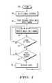
- FIG. 1is a flow chart of a method for alerting a person to an event consistent with certain embodiments of the invention.
- FIG. 2is a diagram of an exemplary alert system consistent with certain embodiments of the invention.
- FIG. 3is a further diagram of an exemplary alert system in a vehicle consistent with certain embodiments of the invention.
- FIG. 4is a signal flow diagram of an exemplary alert system consistent with certain embodiments of the invention.
- certain eventscan be detected automatically from video images. For example, drowsiness in the operator of a vehicle or other machine may be detected by processing camera images to detect physical criteria, such as eye movement and blinking. In another example, vehicle lane changes may be detected from images of the road in front of or behind the driver.
- Detection systemsinclude a camera for collecting images, an image processor for extracting salient features of the images, and decision logic to determine if a specified event has occurred (or is likely to occur). While these components are readily available, costs associated with their purchase, installation and use provide barriers to the commercialization of such systems.
- One aspect of the present inventionis the recognition that the basic components of a detection and alerting system are present in many portable electronic devices, such as cellular telephones, personal digital assistants and other portable electronic devices.
- FIG. 1A flow chart of a method for alerting a person to an event is shown in FIG. 1 .
- a visual criterion by which the event to be detectedis selected at block 104 .
- the portable electronic deviceis positioned such that a camera of the electronic device is orientated to capture images relating to the visual criterion.
- the captured imagesare processed on a processor of the portable electronic device to extract relevant features.
- a decisionis made as to whether the event has occurred (or is likely to occur in the near future).
- decision block 112decision logic is used to determine if an alert is required. If an alert is required, as depicted by the positive branch from decision block 112 , an alert is activated at block 114 . If no event has occurred, as depicted by the negative branch from decision block 110 , or if no alert is required, as depicted by the negative branch from decision block 112 , flow returns to block 108 .
- the decision logicmay additionally use information from sources other than the images captured by the camera, for example, weather and road conditions and vehicle state (such as speed) may be used to make the decision.
- sources other than the images captured by the camerafor example, weather and road conditions and vehicle state (such as speed) may be used to make the decision.
- the eventmay be drowsiness in the person, in which case the camera is oriented towards the head of the person. Drowsiness may be detected by eye movement, blinking frequency/duration, head angle or other visual criteria.
- the personmay be alerted using visual (a flashing light, for example), audio (beeping or other sound) or haptic (vibration, for example) cues.
- the eventmay be a lane change by a motor vehicle.
- the camerais oriented towards the road.
- Features relating to lane markings or a road edgeare extracted from the images and used to determine if the vehicle has moved out of its lane.
- the eventmay be the driver operating the vehicle without enabling different aspects of the system.
- the portable electronic devicemay detect that the vehicle alert system is disabled.
- the eventmay be the driver leaving the motor vehicle without removing the portable electronic device. The associated alert reminds the driver to retrieve the portable electronic device.
- the portable electronic deviceis positioned to detect motion, as in a security system, for example.
- the alertmay be the sounding of an audio alarm, or the transmission of a message over a telephone or data network.
- FIG. 2is a diagram of an exemplary alert system 200 .
- the alert system 200includes a portable electronic device 202 that houses a camera 204 for capturing images of a visual characteristic, such as the head 206 of a person.
- the portable electronic device 202also houses a processor 208 that is operable to process images from the camera 204 .
- the portable electronic device 202may also have a communication circuit 210 operable to provide communication with an external alert system 212 and/or a network 214 .
- the communication circuitmay use a wired or wireless communication link.
- the portable electronic device 202is a cellular telephone.
- the communication circuitprovides a cellular telephone link to a voice and/or data network 214 and may also provide a short range wireless link, such as a Bluetooth connection, to a local network 214 or the alert system 212 .
- the alert system 212may be an external alert system, or an alert system internal to the device.
- the cellular telephonemay activate a ring tone when an event is detected.
- the user interface on the portable electronic devicecan be customized for each vehicle model and type.
- the drivercan select and personalize the settings on the portable electronic device based on the driver's preference in terms of the methods to alert the driver.
- the driver's preference in terms of driving habitscan be selected from the user interface on the portable electronic device.
- the user's interaction with the user interfacemay be used to select which application to execute and to select inputs to the application. These inputs may be data or control inputs that affect the operation of the application.
- the portable electronic device 202is a Personal Digital Assistant (PDA).
- PDAPersonal Digital Assistant
- the communication circuit 210may provide a wireless Internet link and may also provide a short range wireless link, such as a Bluetooth connection, to a local network 214 or the alert system 212 .
- the network 214may be a voice or data network.
- the data networkmay be a local network (such as a vehicle data network) or a wide area network (such as the Internet).
- the network 214may be used to download the software application (the program of instructions) that is used in the method of FIG. 1 .
- the usermay select from a list of software applications that can be downloaded onto the portable electronic device such that the downloaded software application updates the processing blocks ( 108 , 110 , 112 , 114 ).
- the usermay select and download from a list applications related to drowsy driver detection using the network 214 .
- the process of software application selection and downloadmay result in a business transaction in which the application is purchased for use on the portable electronic device.
- the network 214may also be a vehicle network in which processors that control vehicle operation reside.
- the portable electronic device 202may send control signals through the network 214 such as to change certain aspects that pertain to vehicle operation. For example, referring to FIG. 1 , the portable electronic device 202 may turn on the external vehicle lighting to improve the brightness and quality of the image for processing 108 . In yet another example and referring to FIG. 1 , the portable electronic device 202 may enable the turn signals when the event related to an unintended lane change is detected at decision block 110 .
- FIG. 3An example configuration is shown in FIG. 3 .
- a portable digital device( 202 , 202 ′, 202 ′′) is located inside of a vehicle.
- the portable digital device ( 202 , 202 ′, 202 ′′)is held in position at the periphery of a windscreen 302 by means of a holder ( 304 , 304 ′, 304 ′′).
- the holdermaintains the portable electronic device in a position such that the specified visual characteristic can be captured by the camera.
- the holdermay be attached to the rear view mirror 306 , dashboard 308 or windscreen 302 of the vehicle, for example.
- the holder 304may include the capability to charge and/or power the portable electronic device or to connect the portable electronic device to an information system of the vehicle (either via a wired or wireless connection).
- the portable electronic device 202may receive information (such as speed, turn signal activation) from the vehicle information system. This information may be used to adjust the alert sensitivity.
- the portable electronic devicemay communicate the likelihood of event occurrence to the vehicle information system. The vehicle can respond by activating alerts and/or performing actions such as slowing down or activating turn signals.
- the portable electronic devicemay communicate with the alert system via the holder.
- the holderis operable to adjust the orientation of the portable electronic device automatically.
- the position of a visual feature within one or more image framesmay be used as a measure of orientation.
- the holdermay be rotated to move the visual feature to a preferred position within the frame.
- the holder positionmay be adjusted by the user to adjust the orientation of the portable electronic device based on feedback provided by the portable electronic device.
- This feedbackmay include a visual interface on the display on the portable electronic device to indicate the proper orientation for operation of the application.
- this feedbackmay be an audible signal operable through the loudspeaker on the portable electronic device.
- the holdermay incorporate lighting capability to illuminate the area in which the camera on the portable electronic device is aimed.
- the holdermay include infrared LEDs to illuminate the driver so that image contrast is improved for processing 108 .
- the operation of the LEDsare controlled by the portable electronic device.
- the portable electronic devicemay have access to an external network, such as the Internet, from which external environmental information (traffic and weather reports for example) may be received and used to adjust alert sensitivity.
- an external networksuch as the Internet
- the operation of the telephonemay be controlled by the alert system. For example, if a lane change is detected incoming telephone calls may be routed to voice mail or delayed.
- Part of the image processing and event detectionmay be performed external to the portable electronic device.
- the holder( 304 in FIG. 3 ) may include a data processor.
- the camera of the portable electronic deviceis oriented towards the driver of the vehicle.
- the camera of the portable electronic deviceis oriented towards the road ahead of the vehicle, so as to capture images from which the position of the vehicle on the road can be determined. For example, road edges or line markers may be identified and used to detect when the vehicle changes lanes. A determination is then made as to whether the lane change was intentional, and an alert is sounded if it is determined that the lane change is unintentional. For example, if a turn signal is activated the alarm is not activated.
- the holder 304includes a means, such as a clip or pouch, for supporting a portable electronic device such that a camera of the portable electronic device is oriented to capture images relating to a visual characteristic of the event.
- the holderincludes a means, such as an electrical or optical connector, for transferring images from the portable device to the holder and a processor for processing the images transferred from the portable electronic device. The images are processed to detect the event. The processing may be shared between the processor of the holder and the processor of the portable electronic device.
- a communication circuit in the holderis used to signal an alert system. The communication circuit may drive a wired or wireless link.
- the holdermay operate to couple the portable electronic device to a power supply so that the portable electronic device may be operated without loss of battery power. The power supply may be used to charge the battery of the portable electronic device.
- FIG. 4is a signal flow diagram of an exemplary alert system consistent with certain embodiments of the invention.
- images 402are received from a camera of the portable electronic device.
- Feature extraction module 404operates to identify and extract specific features in the images.
- a description 406 of the featuresis passed to a feature analysis module 408 that operates to analyze the features with respect to a selected visual criterion of an event.
- the results 410 of the analysisare passed to an event detection module 412 that determines the likelihood 414 of an event having occurred.
- a decision logic module 416uses the event likelihood 414 together with local information 418 and area information 420 to decide if an alert should be activated.
- the local informationmay be, for example, the operating state of a vehicle and may include parameters such as the speed of the vehicle, the position of turn indicators and outside temperature. This information may be received from a vehicle data bus for example.
- the area informationmay include traffic and weather conditions in the surrounding area. This information may be received by the portable electronic device from a wide area network, such as the Internet. If it is decided that an alert is appropriate, a signal 422 is sent to the alert system 424 .
- the alert systemmay be part of the portable electronic device or it may be an external alert system.
Landscapes
- Physics & Mathematics (AREA)
- Engineering & Computer Science (AREA)
- General Physics & Mathematics (AREA)
- Automation & Control Theory (AREA)
- Mathematical Physics (AREA)
- Transportation (AREA)
- Mechanical Engineering (AREA)
- Business, Economics & Management (AREA)
- Emergency Management (AREA)
- Traffic Control Systems (AREA)
- Emergency Alarm Devices (AREA)
- Telephone Function (AREA)
Abstract
Description
Claims (22)
Priority Applications (2)
| Application Number | Priority Date | Filing Date | Title |
|---|---|---|---|
| US11/277,377US7482937B2 (en) | 2006-03-24 | 2006-03-24 | Vision based alert system using portable device with camera |
| PCT/US2007/062804WO2007112169A2 (en) | 2006-03-24 | 2007-02-26 | Vision based alert system using portable device with camera |
Applications Claiming Priority (1)
| Application Number | Priority Date | Filing Date | Title |
|---|---|---|---|
| US11/277,377US7482937B2 (en) | 2006-03-24 | 2006-03-24 | Vision based alert system using portable device with camera |
Publications (2)
| Publication Number | Publication Date |
|---|---|
| US20070222617A1 US20070222617A1 (en) | 2007-09-27 |
| US7482937B2true US7482937B2 (en) | 2009-01-27 |
Family
ID=38532801
Family Applications (1)
| Application Number | Title | Priority Date | Filing Date |
|---|---|---|---|
| US11/277,377Expired - Fee RelatedUS7482937B2 (en) | 2006-03-24 | 2006-03-24 | Vision based alert system using portable device with camera |
Country Status (2)
| Country | Link |
|---|---|
| US (1) | US7482937B2 (en) |
| WO (1) | WO2007112169A2 (en) |
Cited By (13)
| Publication number | Priority date | Publication date | Assignee | Title |
|---|---|---|---|---|
| US20090040308A1 (en)* | 2007-01-15 | 2009-02-12 | Igor Temovskiy | Image orientation correction method and system |
| US20090292758A1 (en)* | 2008-05-23 | 2009-11-26 | International Business Machines Corporation | Optimized Corner Turns for Local Storage and Bandwidth Reduction |
| US20090300091A1 (en)* | 2008-05-30 | 2009-12-03 | International Business Machines Corporation | Reducing Bandwidth Requirements for Matrix Multiplication |
| US20100157061A1 (en)* | 2008-12-24 | 2010-06-24 | Igor Katsman | Device and method for handheld device based vehicle monitoring and driver assistance |
| US20100238034A1 (en)* | 2009-03-23 | 2010-09-23 | Toyota Motor Engineering & Manufacturing North America, Inc. | System for rapid detection of drowsiness in a machine operator |
| US20110092249A1 (en)* | 2009-10-21 | 2011-04-21 | Xerox Corporation | Portable blind aid device |
| US20110205383A1 (en)* | 2010-02-24 | 2011-08-25 | Research In Motion Limited | Eye blink avoidance during image acquisition in a mobile communications device with digital camera functionality |
| DE102011084552A1 (en)* | 2011-10-14 | 2012-08-02 | Robert Bosch Gmbh | Mobile device e.g. smart phone, for recognition of vigilance of driver of motor car, has camera integrated into device, which monitors and evaluates eyelid closing and iris activity to determine vigilance of person and outputs warning |
| US20150124150A1 (en)* | 2012-04-27 | 2015-05-07 | Denso Corporation | Imaging mechanism and forward-monitoring camera using same imaging mechanism |
| WO2016127204A1 (en)* | 2015-02-12 | 2016-08-18 | Seeing Machines Limited | Automotive phone docking station for enhanced driving safety |
| US10065651B2 (en) | 2016-05-10 | 2018-09-04 | Samsung Electronics Co., Ltd | Electronic device and method for determining a state of a driver |
| US20200108782A1 (en)* | 2017-03-31 | 2020-04-09 | Ford Global Technologies, Llc | Vehicle mobile device holder |
| US11568566B2 (en) | 2016-07-08 | 2023-01-31 | Toyota Motor Engineering & Manufacturing North America. Inc. | Aligning vision-assist device cameras based on physical characteristics of a user |
Families Citing this family (27)
| Publication number | Priority date | Publication date | Assignee | Title |
|---|---|---|---|---|
| US9662977B2 (en)* | 2008-01-02 | 2017-05-30 | Hi Tech Robotic Systemz Ltd. | Driver state monitoring system |
| US8669857B2 (en)* | 2010-01-13 | 2014-03-11 | Denso International America, Inc. | Hand-held device integration for automobile safety |
| US8471691B2 (en)* | 2010-06-15 | 2013-06-25 | GM Global Technology Operations LLC | Portable vision system |
| US8698639B2 (en)* | 2011-02-18 | 2014-04-15 | Honda Motor Co., Ltd. | System and method for responding to driver behavior |
| US9443152B2 (en)* | 2011-05-03 | 2016-09-13 | Ionroad Technologies Ltd. | Automatic image content analysis method and system |
| CN102201148A (en)* | 2011-05-25 | 2011-09-28 | 北京航空航天大学 | Driver fatigue detecting method and system based on vision |
| WO2013113947A1 (en) | 2012-02-01 | 2013-08-08 | Fico Mirrors, Sa | Method and system for inferring the behaviour or state of the driver of a vehicle, use method and computer program for carrying out said method |
| FR2986642B1 (en) | 2012-02-06 | 2015-06-05 | Renault Sa | PROCESSING DATA OF A MOTOR VEHICLE ON AN ORDIPHONE |
| WO2013178869A1 (en)* | 2012-06-01 | 2013-12-05 | Biisafe Oy | Mobile device, stand, arrangement, and method for alarm provision |
| US9751534B2 (en) | 2013-03-15 | 2017-09-05 | Honda Motor Co., Ltd. | System and method for responding to driver state |
| DE102013209999B4 (en)* | 2013-05-29 | 2025-07-10 | Robert Bosch Gmbh | Method and device for detecting a collision between a vehicle and an object using a mobile terminal that can be coupled to the vehicle |
| DE102013012181A1 (en)* | 2013-07-22 | 2015-01-22 | GM Global Technology Operations LLC (n. d. Gesetzen des Staates Delaware) | Device for controlling a direction indicator |
| US20150170116A1 (en)* | 2013-11-26 | 2015-06-18 | Transcast, Inc. | Online self contained portable interactive transactional system |
| US20150178714A1 (en)* | 2013-11-26 | 2015-06-25 | Transcast, Inc. | Method for providing connectivity from a transport vehicle |
| US20160118036A1 (en) | 2014-10-23 | 2016-04-28 | Elwha Llc | Systems and methods for positioning a user of a hands-free intercommunication system |
| US20150334346A1 (en)* | 2014-05-16 | 2015-11-19 | Elwha Llc | Systems and methods for automatically connecting a user of a hands-free intercommunication system |
| US9779593B2 (en)* | 2014-08-15 | 2017-10-03 | Elwha Llc | Systems and methods for positioning a user of a hands-free intercommunication system |
| US9565284B2 (en) | 2014-04-16 | 2017-02-07 | Elwha Llc | Systems and methods for automatically connecting a user of a hands-free intercommunication system |
| DE102014214078A1 (en)* | 2014-07-18 | 2016-01-21 | Continental Automotive Gmbh | Method for interacting with a driver of a vehicle during automated driving |
| JP6337710B2 (en)* | 2014-09-17 | 2018-06-06 | 日産自動車株式会社 | Communication control device and communication control method |
| KR101646401B1 (en)* | 2014-12-08 | 2016-08-12 | 현대자동차주식회사 | System and method for determining drowsy state of driver |
| KR102266712B1 (en) | 2015-01-12 | 2021-06-21 | 엘지전자 주식회사 | Mobile terminal and method for controlling the same |
| CN105788174A (en)* | 2016-05-04 | 2016-07-20 | 成都贝森伟任科技有限责任公司 | Vehicle anti-collision terminal for preventing fatigue driving |
| DE102017200148B4 (en)* | 2017-01-09 | 2021-01-28 | Ford Global Technologies, Llc | Method for using sensors of a mobile terminal with a vehicle, vehicle, computer program and computer-readable medium |
| US10445559B2 (en) | 2017-02-28 | 2019-10-15 | Wipro Limited | Methods and systems for warning driver of vehicle using mobile device |
| CN107031652A (en)* | 2017-03-28 | 2017-08-11 | 安徽师范大学 | Driving behavior appraisal procedure |
| US11427207B1 (en)* | 2019-08-29 | 2022-08-30 | United Services Automobile Association (Usaa) | Systems and methods for controlling vehicle systems based on driver assessment |
Citations (12)
| Publication number | Priority date | Publication date | Assignee | Title |
|---|---|---|---|---|
| US20020149695A1 (en)* | 2001-04-12 | 2002-10-17 | Yasunobu Kayanuma | Cradle for information apparatus, cradle for digital camera and camera system |
| US20030096593A1 (en) | 2001-10-24 | 2003-05-22 | Naboulsi Mouhamad Ahmad | Safety control system for vehicles |
| US20030209893A1 (en) | 1992-05-05 | 2003-11-13 | Breed David S. | Occupant sensing system |
| US6717518B1 (en) | 1998-01-15 | 2004-04-06 | Holding B.E.V.S.A. | Method and apparatus for detection of drowsiness |
| US20040110544A1 (en)* | 2001-04-03 | 2004-06-10 | Masayuki Oyagi | Cradle, security system, telephone, and monitoring method |
| US20040183685A1 (en)* | 2003-03-18 | 2004-09-23 | Ford Global Technologies, Llc | Drowsy driver monitoring and prevention system |
| US20050032550A1 (en) | 2000-03-22 | 2005-02-10 | Ronald Baratono | Combined rear view mirror and telephone |
| US20050030184A1 (en) | 2003-06-06 | 2005-02-10 | Trent Victor | Method and arrangement for controlling vehicular subsystems based on interpreted driver activity |
| US20050219058A1 (en)* | 2003-05-16 | 2005-10-06 | Fujitsu Limited | Alarm system, alarm control apparatus and alarm control program |
| US20060103513A1 (en)* | 2004-10-22 | 2006-05-18 | Toru Ihara | Alert system installed in vehicle |
| US7190263B2 (en)* | 2004-09-20 | 2007-03-13 | Motorola, Inc. | Utilizing a portable electronic device to detect motion |
| US20070085674A1 (en)* | 2005-10-14 | 2007-04-19 | Sharpe Jon B | Self-contained cellular security system |
- 2006
- 2006-03-24USUS11/277,377patent/US7482937B2/ennot_activeExpired - Fee Related
- 2007
- 2007-02-26WOPCT/US2007/062804patent/WO2007112169A2/enactiveApplication Filing
Patent Citations (12)
| Publication number | Priority date | Publication date | Assignee | Title |
|---|---|---|---|---|
| US20030209893A1 (en) | 1992-05-05 | 2003-11-13 | Breed David S. | Occupant sensing system |
| US6717518B1 (en) | 1998-01-15 | 2004-04-06 | Holding B.E.V.S.A. | Method and apparatus for detection of drowsiness |
| US20050032550A1 (en) | 2000-03-22 | 2005-02-10 | Ronald Baratono | Combined rear view mirror and telephone |
| US20040110544A1 (en)* | 2001-04-03 | 2004-06-10 | Masayuki Oyagi | Cradle, security system, telephone, and monitoring method |
| US20020149695A1 (en)* | 2001-04-12 | 2002-10-17 | Yasunobu Kayanuma | Cradle for information apparatus, cradle for digital camera and camera system |
| US20030096593A1 (en) | 2001-10-24 | 2003-05-22 | Naboulsi Mouhamad Ahmad | Safety control system for vehicles |
| US20040183685A1 (en)* | 2003-03-18 | 2004-09-23 | Ford Global Technologies, Llc | Drowsy driver monitoring and prevention system |
| US20050219058A1 (en)* | 2003-05-16 | 2005-10-06 | Fujitsu Limited | Alarm system, alarm control apparatus and alarm control program |
| US20050030184A1 (en) | 2003-06-06 | 2005-02-10 | Trent Victor | Method and arrangement for controlling vehicular subsystems based on interpreted driver activity |
| US7190263B2 (en)* | 2004-09-20 | 2007-03-13 | Motorola, Inc. | Utilizing a portable electronic device to detect motion |
| US20060103513A1 (en)* | 2004-10-22 | 2006-05-18 | Toru Ihara | Alert system installed in vehicle |
| US20070085674A1 (en)* | 2005-10-14 | 2007-04-19 | Sharpe Jon B | Self-contained cellular security system |
Cited By (20)
| Publication number | Priority date | Publication date | Assignee | Title |
|---|---|---|---|---|
| US20090040308A1 (en)* | 2007-01-15 | 2009-02-12 | Igor Temovskiy | Image orientation correction method and system |
| US20090292758A1 (en)* | 2008-05-23 | 2009-11-26 | International Business Machines Corporation | Optimized Corner Turns for Local Storage and Bandwidth Reduction |
| US8554820B2 (en) | 2008-05-23 | 2013-10-08 | International Business Machines Corporation | Optimized corner turns for local storage and bandwidth reduction |
| US8533251B2 (en) | 2008-05-23 | 2013-09-10 | International Business Machines Corporation | Optimized corner turns for local storage and bandwidth reduction |
| US8250130B2 (en)* | 2008-05-30 | 2012-08-21 | International Business Machines Corporation | Reducing bandwidth requirements for matrix multiplication |
| US20090300091A1 (en)* | 2008-05-30 | 2009-12-03 | International Business Machines Corporation | Reducing Bandwidth Requirements for Matrix Multiplication |
| US20100157061A1 (en)* | 2008-12-24 | 2010-06-24 | Igor Katsman | Device and method for handheld device based vehicle monitoring and driver assistance |
| US20100238034A1 (en)* | 2009-03-23 | 2010-09-23 | Toyota Motor Engineering & Manufacturing North America, Inc. | System for rapid detection of drowsiness in a machine operator |
| US8040247B2 (en)* | 2009-03-23 | 2011-10-18 | Toyota Motor Engineering & Manufacturing North America, Inc. | System for rapid detection of drowsiness in a machine operator |
| US20110092249A1 (en)* | 2009-10-21 | 2011-04-21 | Xerox Corporation | Portable blind aid device |
| US8606316B2 (en)* | 2009-10-21 | 2013-12-10 | Xerox Corporation | Portable blind aid device |
| US20110205383A1 (en)* | 2010-02-24 | 2011-08-25 | Research In Motion Limited | Eye blink avoidance during image acquisition in a mobile communications device with digital camera functionality |
| DE102011084552A1 (en)* | 2011-10-14 | 2012-08-02 | Robert Bosch Gmbh | Mobile device e.g. smart phone, for recognition of vigilance of driver of motor car, has camera integrated into device, which monitors and evaluates eyelid closing and iris activity to determine vigilance of person and outputs warning |
| US20150124150A1 (en)* | 2012-04-27 | 2015-05-07 | Denso Corporation | Imaging mechanism and forward-monitoring camera using same imaging mechanism |
| WO2016127204A1 (en)* | 2015-02-12 | 2016-08-18 | Seeing Machines Limited | Automotive phone docking station for enhanced driving safety |
| EP3257163A4 (en)* | 2015-02-12 | 2018-10-24 | Seeing Machines Limited | Automotive phone docking station for enhanced driving safety |
| US11223381B2 (en) | 2015-02-12 | 2022-01-11 | Seeing Machines Limited | Phone docking station mounted on a vehicle for enhanced driving safety |
| US10065651B2 (en) | 2016-05-10 | 2018-09-04 | Samsung Electronics Co., Ltd | Electronic device and method for determining a state of a driver |
| US11568566B2 (en) | 2016-07-08 | 2023-01-31 | Toyota Motor Engineering & Manufacturing North America. Inc. | Aligning vision-assist device cameras based on physical characteristics of a user |
| US20200108782A1 (en)* | 2017-03-31 | 2020-04-09 | Ford Global Technologies, Llc | Vehicle mobile device holder |
Also Published As
| Publication number | Publication date |
|---|---|
| US20070222617A1 (en) | 2007-09-27 |
| WO2007112169B1 (en) | 2008-06-19 |
| WO2007112169A3 (en) | 2008-05-02 |
| WO2007112169A2 (en) | 2007-10-04 |
Similar Documents
| Publication | Publication Date | Title |
|---|---|---|
| US7482937B2 (en) | Vision based alert system using portable device with camera | |
| JP7060031B2 (en) | Driver monitoring system | |
| US10647252B2 (en) | Portable electronic device and operating method therefor | |
| CN106004883B (en) | The method and device that rule-breaking vehicle is reminded | |
| US10204261B2 (en) | Camera in vehicle reports identity of driver | |
| JP5872764B2 (en) | Image display system | |
| US20150094118A1 (en) | Mobile device edge view display insert | |
| US11676404B2 (en) | Vehicular driver monitoring system with customized outputs | |
| US20090167516A1 (en) | Look-away detecting device, method and program | |
| WO2016206294A1 (en) | Balanced car management method and device | |
| US9734412B2 (en) | Method and system of communicating vehicle information | |
| JP2004519788A (en) | A system that monitors the driver's attention to driving | |
| JP2010217956A (en) | Information processing apparatus and method, program, and information processing system | |
| US20150158426A1 (en) | Apparatus, control method thereof and computer-readable storage medium | |
| US20140118131A1 (en) | Monitoring and warning system for vehicles | |
| JP2006174288A (en) | Mobile terminal device, collision prevention method, collision prevention program, and recording medium | |
| CN109747540A (en) | The method of integrated driving person's auxiliary system, corresponding system, circuit, external member | |
| JP2013041489A (en) | On-vehicle camera control unit, on-vehicle camera control system and on-vehicle camera system | |
| CN109104689B (en) | A safety warning method and terminal | |
| CN108417061B (en) | Method and device for detecting the signal state of at least one signaling device | |
| JP2022126492A (en) | VEHICLE CONTROL DEVICE AND VEHICLE CONTROL METHOD | |
| JP2010123100A (en) | Traffic signal detection/notification system | |
| JP4039075B2 (en) | Mobile information terminal with front obstacle detection function | |
| WO2017150466A1 (en) | Driver monitoring system | |
| TWI798001B (en) | Method and system of gesture control driving recorder |
Legal Events
| Date | Code | Title | Description |
|---|---|---|---|
| AS | Assignment | Owner name:MOTOROLA, INC., ILLINOIS Free format text:ASSIGNMENT OF ASSIGNORS INTEREST;ASSIGNORS:CHAI, SEK M.;KUJAWA, GREGORY A.;REEL/FRAME:017359/0460 Effective date:20060323 | |
| STCF | Information on status: patent grant | Free format text:PATENTED CASE | |
| AS | Assignment | Owner name:MOTOROLA MOBILITY, INC, ILLINOIS Free format text:ASSIGNMENT OF ASSIGNORS INTEREST;ASSIGNOR:MOTOROLA, INC;REEL/FRAME:025673/0558 Effective date:20100731 | |
| FPAY | Fee payment | Year of fee payment:4 | |
| AS | Assignment | Owner name:MOTOROLA MOBILITY LLC, ILLINOIS Free format text:CHANGE OF NAME;ASSIGNOR:MOTOROLA MOBILITY, INC.;REEL/FRAME:029216/0282 Effective date:20120622 | |
| AS | Assignment | Owner name:GOOGLE TECHNOLOGY HOLDINGS LLC, CALIFORNIA Free format text:ASSIGNMENT OF ASSIGNORS INTEREST;ASSIGNOR:MOTOROLA MOBILITY LLC;REEL/FRAME:034419/0001 Effective date:20141028 | |
| FPAY | Fee payment | Year of fee payment:8 | |
| FEPP | Fee payment procedure | Free format text:MAINTENANCE FEE REMINDER MAILED (ORIGINAL EVENT CODE: REM.); ENTITY STATUS OF PATENT OWNER: LARGE ENTITY | |
| LAPS | Lapse for failure to pay maintenance fees | Free format text:PATENT EXPIRED FOR FAILURE TO PAY MAINTENANCE FEES (ORIGINAL EVENT CODE: EXP.); ENTITY STATUS OF PATENT OWNER: LARGE ENTITY | |
| STCH | Information on status: patent discontinuation | Free format text:PATENT EXPIRED DUE TO NONPAYMENT OF MAINTENANCE FEES UNDER 37 CFR 1.362 | |
| FP | Lapsed due to failure to pay maintenance fee | Effective date:20210127 |