US7481827B2 - Linking transconnector for coupling spinal rods - Google Patents
Linking transconnector for coupling spinal rodsDownload PDFInfo
- Publication number
- US7481827B2 US7481827B2US10/684,351US68435103AUS7481827B2US 7481827 B2US7481827 B2US 7481827B2US 68435103 AUS68435103 AUS 68435103AUS 7481827 B2US7481827 B2US 7481827B2
- Authority
- US
- United States
- Prior art keywords
- rod
- lateral rod
- transconnector
- hook
- locking sleeve
- Prior art date
- Legal status (The legal status is an assumption and is not a legal conclusion. Google has not performed a legal analysis and makes no representation as to the accuracy of the status listed.)
- Expired - Lifetime, expires
Links
- 230000008878couplingEffects0.000titleclaimsabstractdescription12
- 238000010168coupling processMethods0.000titleclaimsabstractdescription12
- 238000005859coupling reactionMethods0.000titleclaimsabstractdescription12
- 238000009434installationMethods0.000description19
- 208000014674injuryDiseases0.000description5
- 230000008733traumaEffects0.000description5
- 230000013011matingEffects0.000description4
- 238000000034methodMethods0.000description4
- 230000008569processEffects0.000description4
- 230000000717retained effectEffects0.000description4
- 210000004872soft tissueAnatomy0.000description4
- 238000002788crimpingMethods0.000description2
- 230000007246mechanismEffects0.000description2
- 238000012986modificationMethods0.000description2
- 230000004048modificationEffects0.000description2
- 238000000926separation methodMethods0.000description2
- 210000001519tissueAnatomy0.000description2
- 208000000875Spinal CurvaturesDiseases0.000description1
- 208000020307Spinal diseaseDiseases0.000description1
- 229910001069Ti alloyInorganic materials0.000description1
- RTAQQCXQSZGOHL-UHFFFAOYSA-NTitaniumChemical compound[Ti]RTAQQCXQSZGOHL-UHFFFAOYSA-N0.000description1
- 230000009471actionEffects0.000description1
- 229910045601alloyInorganic materials0.000description1
- 239000000956alloySubstances0.000description1
- 230000004075alterationEffects0.000description1
- 230000000712assemblyEffects0.000description1
- 238000000429assemblyMethods0.000description1
- 230000006835compressionEffects0.000description1
- 238000007906compressionMethods0.000description1
- 230000003412degenerative effectEffects0.000description1
- 230000009977dual effectEffects0.000description1
- 230000004927fusionEffects0.000description1
- 210000003041ligamentAnatomy0.000description1
- 210000004705lumbosacral regionAnatomy0.000description1
- 239000000463materialSubstances0.000description1
- 230000000399orthopedic effectEffects0.000description1
- 229920000642polymerPolymers0.000description1
- 230000001737promoting effectEffects0.000description1
- 206010039722scoliosisDiseases0.000description1
- 239000010935stainless steelSubstances0.000description1
- 229910001220stainless steelInorganic materials0.000description1
- 238000001356surgical procedureMethods0.000description1
- 210000000115thoracic cavityAnatomy0.000description1
- 229910052719titaniumInorganic materials0.000description1
- 239000010936titaniumSubstances0.000description1
Images


Classifications
- A—HUMAN NECESSITIES
- A61—MEDICAL OR VETERINARY SCIENCE; HYGIENE
- A61B—DIAGNOSIS; SURGERY; IDENTIFICATION
- A61B17/00—Surgical instruments, devices or methods
- A61B17/56—Surgical instruments or methods for treatment of bones or joints; Devices specially adapted therefor
- A61B17/58—Surgical instruments or methods for treatment of bones or joints; Devices specially adapted therefor for osteosynthesis, e.g. bone plates, screws or setting implements
- A61B17/68—Internal fixation devices, including fasteners and spinal fixators, even if a part thereof projects from the skin
- A61B17/70—Spinal positioners or stabilisers, e.g. stabilisers comprising fluid filler in an implant
- A61B17/7049—Connectors, not bearing on the vertebrae, for linking longitudinal elements together
- A—HUMAN NECESSITIES
- A61—MEDICAL OR VETERINARY SCIENCE; HYGIENE
- A61B—DIAGNOSIS; SURGERY; IDENTIFICATION
- A61B17/00—Surgical instruments, devices or methods
- A61B17/56—Surgical instruments or methods for treatment of bones or joints; Devices specially adapted therefor
- A61B17/58—Surgical instruments or methods for treatment of bones or joints; Devices specially adapted therefor for osteosynthesis, e.g. bone plates, screws or setting implements
- A61B17/68—Internal fixation devices, including fasteners and spinal fixators, even if a part thereof projects from the skin
- A61B17/82—Internal fixation devices, including fasteners and spinal fixators, even if a part thereof projects from the skin for bone cerclage
- Y—GENERAL TAGGING OF NEW TECHNOLOGICAL DEVELOPMENTS; GENERAL TAGGING OF CROSS-SECTIONAL TECHNOLOGIES SPANNING OVER SEVERAL SECTIONS OF THE IPC; TECHNICAL SUBJECTS COVERED BY FORMER USPC CROSS-REFERENCE ART COLLECTIONS [XRACs] AND DIGESTS
- Y10—TECHNICAL SUBJECTS COVERED BY FORMER USPC
- Y10T—TECHNICAL SUBJECTS COVERED BY FORMER US CLASSIFICATION
- Y10T403/00—Joints and connections
- Y10T403/32—Articulated members
- Y10T403/32008—Plural distinct articulation axes
- Y10T403/32032—Plural ball and socket
Definitions
- the present inventionrelates to a device for spinal fixation, and in particular to a transconnector for coupling adjacent spinal rods, or other elongated members.
- a pair of elongated memberstypically either rods or plates, longitudinally placed on the posterior spine on either side of spinous processes of the vertebral column.
- rodwill be used hereafter to refer to any elongated member regardless of size and/or shape.
- attachment devicesmay include, but are not limited to, pedicle screws, plates, transverse process hooks, sublaminar hooks, pedicle hooks, clamps, wire, etc.
- transconnectorscan provide surgeons with one or more difficulties.
- the simplest situation in which a transconnector could be usedoccurs when the two rods are parallel to each other, i.e. there is no rod convergence or divergence in the medial-lateral direction; where the two rods have the same orientation with respect to the coronal plane viewed in the anterior-posterior direction, i.e. the rods are coplanar from a lateral view; and where the two rods are located at a fixed, predetermined distance from each other.
- the two rodsare rarely so geometrically aligned in clinical situations.
- transconnectorwhich may be adjusted to adapt to variations in spinal rod alignment.
- the addition of such adjustabilitymay require the transconnector to consist of numerous pieces that can be difficult to assemble and use while in the surgical environment.
- transconnectorswhen transconnectors are placed over adjacent spinal rods, the extended profile of the device often results in soft tissue trauma and may result in surgical complications.
- transconnectorthat, once assembled, prevents disassembly of the individual pieces of the transconnector assembly, thereby helping to facilitate installation of the transconnector by reducing the likelihood that the transconnector will accidentally come apart during installation in the patient. It is also advantageous to provide a transconnector that reduces the overall number of steps required to fix the location of the transconnector with respect to the longitudinal spinal rods, thereby facilitating installation of the transconnector by reducing the time and effort needed for installation in the patient.
- the present inventionrelates to a Linking Transconnector used for coupling a first longitudinal spinal rod to a second longitudinal spinal rod.
- the Linking Transconnectorgenerally includes a pair of hook engaging members for engaging the longitudinal spinal rods, a lateral rod for spanning a distance between the hook engaging members, and a locking element which interconnects the hook engaging members with the lateral rod.
- the locking elementgenerally includes a locking sleeve and a bushing, the locking sleeve being slidably located on the lateral rod thereby permitting the Linking Transconnector to accommodate varying distances between the longitudinal spinal rods, while the bushing is sized and dimensioned to be disposed between the locking sleeve and the hook engaging members thereby permitting universal adjustment between the hook engaging members and the lateral rod, and thus between the longitudinal spinal rods and the lateral rod.
- the locking elementis configured to provide multiple degrees of adjustment including both telescoping adjustment and universal adjustment to permit the Linking Transconnector to accommodate varying spinal rod alignments including converging and/or diverging longitudinal rods, non-coplanar longitudinal rods, and longitudinal rods having varying rod separation distances.
- the locking elementalso permits the location of the lateral rod to be fixed relative to the hook engaging members once desired position of the lateral rod with respect to the longitudinal spinal rods has been achieved. That is, the locking element may be configured to fix, both rotationally and translationally, the position of the lateral rod with respect to the hook engaging members and thus to the longitudinal spinal rods, by having both a locked and an unlocked position. In the unlocked position, the locking element may permit rotation and telescopic adjustment of the hook engaging members with respect to the lateral rod. In the locked position, the locking element may fix, both rotationally and translationally, the position of the lateral rod with respect to the associated hook engaging member, thus fixing the relative positions of the lateral rod and the longitudinal spinal rod.
- the locking elementmay be configured to the locked position through the application of a force to the locking element. This force may cause the locking sleeve to compress against the outer surface of the lateral rod while simultaneously causing the bushing to expand to engage the hook engaging members, thereby locking the relative positions of the lateral rod, the hook engaging member and the locking element both rotationally and translationally, with respect to one another.
- the lateral rod and locking elementmay also be sized and configured to mate with the hook engaging members such that disassembly of the lateral rod and hook engaging members is prohibited once the Linking Transconnector has been assembled. This helps facilitate installation of the Linking Transconnector by reducing the likelihood that the transconnector will accidentally come apart during installation in the patient.
- the present inventionfurther relates to a transconnector for coupling first and second longitudinal spinal rods, the transconnector including a pair of hook members, each hook member having a recess for receiving one of the longitudinal spinal rods; each recess further having an axis; a lateral rod for interconnecting the hook members; and a pair of universal joints for interconnecting the hook members with the lateral rod; wherein each hook member includes a through bore having an axis for receiving a wedge member, the through bore axis being orientated substantially perpendicular to the recess axis.
- the present inventionfurther relates to a transconnector for coupling first and second longitudinal spinal rods, each spinal rod having a longitudinal axis, the transconnector including a pair of hook members, each hook member having a recess for receiving one of the longitudinal spinal rods and a through bore having an axis for receiving a wedge member, the through bore being orientated substantially perpendicular to the axis of the longitudinal spinal rod; a lateral rod for interconnecting the hook members; and a pair of locking elements for interconnecting the hook members with the lateral rod; wherein the locking element has an unlocked configuration in which the locking element may move, and a locked configuration in which the locking element is fixed.
- the present inventionfurther relates to a transconnector for coupling first and second longitudinal spinal rods, each spinal rod having a longitudinal axis, the transconnector including a pair of hook members, each hook member having a recess for receiving one of the longitudinal spinal rods and a through bore having an axis for receiving a wedge member, the through bore being orientated substantially perpendicular to the axis of the longitudinal spinal rod; and a lateral rod for interconnecting the hook members; the lateral rod including a pair of locking elements one located at either end of the lateral rod for connection to the hook members; the locking elements being sized and configured to provide universal movement between the hook members and the lateral rod; wherein the locking element has an unlocked configuration in which the locking element may move, and a locked configuration in which the locking element is fixed.
- the locking element of the present inventionmay include a locking sleeve and a bushing wherein the locking sleeve has a first end, a second end, and a through bore extending therethrough, the through bore being sized and configured to receive the lateral rod therein.
- the bushinghas a first end, a second end, and a through bore therethrough, the through bore being sized and configured to receive the locking sleeve therein.
- the bushingmay be sized and configured to be slidably moveably along the locking sleeve.
- the locking sleeve and bushingmay also include a slit therethrough for facilitating installation.
- the hook engaging members, locking sleeve and lateral rodmay also be sized and configured so that, once assembled, the hook engaging member will not separate from the bushing, the bushing will be retained on the locking sleeve and the locking sleeve will be retained on the lateral rod. This arrangement ensures that once the Linking Transconnector has been pre-assembled it will remain intact during installation in the patient.
- the Linking Transconnectormay be provided pre-assembled, such that a hook engaging member and locking element are provisionally attached to each end of a lateral rod.
- the Linking Transconnectormay be provided in a pre-assembled form, the lateral rod and hook engaging members may be still rotationally and translationally adjustable relative to one another.
- the pre-assembled Linking Transconnectoris installed between a pair of longitudinal spinal rods by placing the Linking Transconnector at the desired location between the spinal rods.
- the Linking Transconnectoris then adjusted, both rotationally and translationally, until its desired position is achieved. Once achieved, the wedge members in the hook engaging members may be tightened to lock the hook engaging members to the spinal rods.
- a toolis used to engage the locking element so that the locking sleeve and bushing are moved toward each other.
- Thiscauses the locking sleeve to slide within the bushing, which in turn causes increased interference between the outer surface of the locking sleeve and the inner surface of the bushing.
- This interferencecauses the locking sleeve to compress and the bushing to expand, thereby fixing the position of the locking sleeve to the lateral rod, the bushing to the hook engaging member, and the locking sleeve to the bushing.
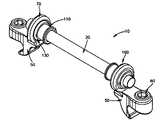
- FIG. 1is a perspective view of the Linking Transconnector according to one embodiment of the present invention.
- FIG. 2is a top view of the Linking Transconnector shown in FIG. 1 .
- FIG. 3is a side cross-sectional view of the Linking Transconnector shown in FIG. 1 .
- FIG. 4is a detailed view of the hook engaging member of the Linking Transconnector shown in FIG. 1 .
- FIG. 5 ais a longitudinal cross-sectional view of the locking sleeve of the Linking Transconnector shown in FIG. 1 .
- FIG. 5 bis a lateral cross-sectional view of the locking sleeve shown in FIG. 5 a.
- FIG. 5 cis a detailed view of the locking sleeve shown in FIG. 5 a.
- FIG. 6 ais a detailed view of the bushing of the Linking Transconnector shown in FIG. 1 .
- FIG. 6 bis a cross-sectional view of the bushing shown in FIG. 6 a.
- the Linking Transconnector 10may be used for coupling a first longitudinal spinal rod to a second longitudinal spinal rod.
- the first and second longitudinal spinal rodsmay be cylindrical rods, rectangular bars, plates, or any other device appropriate for use in connecting two or more adjacent vertebral bodies to facilitate spinal fixation.
- the term “rod”will be used herein to refer to any elongated member regardless of size and/or shape.
- the first and second longitudinal spinal rodsextend along the posterior spine on either side of spinous processes of the vertebral column.
- the first and second longitudinal spinal rodsmay be attached to various vertebral elements along the length of the spine by any attachment device known in the art including, but not limited to, pedicle screws, plates, transverse process hooks, sublaminar hooks, pedicle hooks, clamps, wire, etc.
- the Linking Transconnector 10may be manufactured from any material suitable for orthopedic applications including, but not limited to, stainless steel, titanium, titanium alloy, polymers, memory shaped alloys, etc.
- the Linking Transconnector 10generally includes a pair of hook engaging members 50 for engaging the longitudinal spinal rods (not shown), a lateral rod 20 for spanning a distance between the hook engaging members 50 , and a pair of locking elements 100 which interconnect the hook engaging members 50 with the lateral rod 20 .
- Each hook engaging member 50may include a hook recessed wall 56 for receiving one of the longitudinal spinal rods, a through bore 58 for receiving a wedge member 60 for securing the longitudinal spinal rod into engagement with the hook recessed wall 56 , and a lateral rod engaging portion 70 for receiving the lateral rod 20 therethrough.
- the locking element 100may be configured to provide multiple degrees of freedom to permit the Linking Transconnector 10 to accommodate varying spinal rod alignments.
- the locking element 100permits the lateral rod 20 to angulate and translate with respect to at least one of the hook engaging members 50 , thus permitting the Linking Transconnector 10 to accommodate, for example, converging and/or diverging longitudinal rod pairs, non-coplanar longitudinal rod pairs, and longitudinal rods having varying rod separation distances.
- the locking element 100generally includes a locking sleeve 110 and a bushing 130 .
- the locking sleeve 110may be sized and configured to be slidably positionable along the length of the lateral rod 20 thereby permitting the Linking Transconnector 10 to accommodate varying distances between longitudinal spinal rods.
- the bushing 130may be sized and configured to be positioned between the locking sleeve 110 and the lateral rod engaging portion 70 thereby permitting the lateral rod 20 to be universally adjustable with respect to the hook engaging members 50 , and thus the lateral rod 20 is universally adjustable with respect to the longitudinal spinal rods.
- the locking element 100also may provide for the fixation of the lateral rod 20 with respect to the longitudinal spinal rods once desired positioning of the lateral rod 20 has been achieved. That is, the locking element 100 may be configured to have both locked and unlocked positions. In the unlocked position, the locking element 100 may permit rotation and telescopic adjustment of the hook engaging members 50 with respect to the lateral rod 20 . In the locked position, the locking element 100 may fix, both rotationally and translationally, the position of the lateral rod 20 with respect to the associated hook engaging member 50 , thus fixing the relative positions of the lateral rod 20 and the longitudinal spinal rod. The locking element 100 may be configured to the locked position through the application of a force to the locking element 100 .
- This forcemay cause the locking sleeve 110 to compress against the outer surface of the lateral rod 20 while simultaneously causing the bushing 130 to expand to engage the hook engaging members 50 , thereby locking the relative positions of the lateral rod 20 , the hook engaging member 50 and the locking element 100 both rotationally and translationally, with respect to one another.
- the lateral rod 20 and locking element 100may be sized and configured to prevent disassembly of the lateral rod 20 from the hook engaging members 50 once the Linking Transconnector 10 has been assembled.
- the lateral rodmay be swaged, or flared, at both ends, and the swaged or flared portion may have a diameter greater than the unexpanded inner diameter of the locking element 100 , thereby preventing the locking element 100 from sliding off the end of the lateral rod 20 . This feature helps facilitate installation of the Linking Transconnector 10 during surgery by reducing the chance that the transconnector will accidentally come apart during installation in the patient.
- each hook engaging member 50may include a body 52 having a hook 54 extending therefrom, the hook 54 having a hook recess wall 56 for receiving a longitudinal spinal rod.
- the hook recess wall 56may be sized and configured such that the radius of the hook recess wall 56 conforms to the radius of the associated longitudinal spinal rod to which it will be fixed. However, the hook recess wall 56 may have a radius that is larger or smaller than the radius of the longitudinal spinal rod, as appropriate.
- the hook engaging member 50preferably has a hook recess wall 56 which is positioned laterally inboard from the center of the longitudinal spinal rods.
- the hook engaging member 50may also include a through bore 58 for receiving a wedge member 60 , the through bore being positioned laterally outboard from the center of the associated longitudinal spinal rod.
- the through bore 58may have a longitudinal axis which is orientated substantially perpendicular to the longitudinal axis of the spinal rod.
- the wedge member 60may secure the position of the longitudinal spinal rod relative to the hook engaging member 50 once desired positioning of the lateral rod 20 has been achieved.
- This configuration of hook recessed wall 56 and through bore 58may be such that when the wedge member 60 is rotated so that a bearing surface 62 of the wedge member 60 engages the longitudinal spinal rod, further rotation of the wedge member 60 may cause the longitudinal spinal rod to be urged laterally inwards (i.e., towards the centerline of the patient's spine) into lateral contact with the hook recess wall 56 which is located laterally inboard of the longitudinal spinal rod.
- Thisenables the Linking Transconnector 10 to utilize a hook 54 which contacts a reduced portion of the circumference of the longitudinal spinal rod.
- this configuration of hook recess wall 56 and through bore 58includes a hook 54 which extends around, and contacts, approximately 60° to 180°, preferably approximately 90° of the circumference of the longitudinal spinal rod.
- a hook 54which extends around, and contacts, approximately 60° to 180°, preferably approximately 90° of the circumference of the longitudinal spinal rod.
- the hook recessed wall 56may take on any appropriate shape and configuration.
- the hook recess wall 56may be configured to contact the longitudinal spinal rod up to 360° around the rod's outer circumference (in which case, the hook recessed wall 56 could include a bore sized to receive the longitudinal spinal rod, and the spinal rod would be fed into and through the bore).
- the reduced-contact configuration of through bore 58 and hook designmakes the Linking Transconnector 10 particularly well adapted for use in the cervical region of the spine where little room for spinal fixation components exists.
- the Linking Transconnector 10may also be used to connect longitudinal spinal rods placed in other regions of the spine including the thoracic and lumbar regions.
- the hook engaging members 50may also include one or more tool engagement recesses 57 for receiving a gripping instrument, such as forceps.
- the tool engagement recesses 57may be configured to receive the jaws of a forceps, thereby allowing the Linking Transconnector 10 to be installed and/or manipulated in the patient using forceps engaged with hook engagement members 50 .
- the tool engagement recesses 57preferably are positioned to allow the surgeon to grip the hook engagement members 50 from above, to provide for maneuvering of the Linking Transconnector 10 into position on the vertebra from above, or outside of the patient.
- the tool engagement recesses 57may be formed on each side of the hook engaging members 50 , and they may extend entirely across the outer surface of the hook engaging members 50 or only along a portion thereof.
- the tool engagement recesses 57are not limited to the elongated slots as shown and that other configurations are contemplated.
- the tool engagement recesses 57 and instrument jawsmay have any mating configuration that allows the instrument to securely grasp the hook engaging members 50 .
- the tool engagement recesses 57may provide sufficient grip on the hook engaging members 50 for a surgeon to maneuver the hook engaging members 50 into position through obstructions such as ligaments and other tissues.
- the tool engagement recesses 57are preferably positioned at a sufficient distance and/or orientation with respect to the hook recessed wall 56 to allow the longitudinal spinal rod to be inserted into the hook recessed wall 56 while the tool engagement recesses 57 are engaged by an instrument.
- the tool engagement recesses 57are preferably not located in a position in which the instrument blocks access to the hook recessed wall 56 when the instruments is engaged with the tool engagement recesses 57 .
- the tool engagement recesses 57may also be positioned at a sufficient distance and/or orientation with respect to the wedge member 60 and locking member 100 to allow the wedge member 60 and locking member 100 to be manipulated by the surgeon while the tool engagement recesses 57 are engaged by an instrument.
- the tool engagement recesses 57may also be located on other components of the transconnector such as for example, the lateral rod 20 .
- the wedge member 60may include, but not be limited to, a set screw, a quarter turn cam, etc. Any appropriate locking structure is contemplated which will allow the hook engaging member 50 to be fixed to the longitudinal rod.
- the wedge member 60may have a bearing surface 62 shaped and configured to conform with the outer surface of an associated longitudinal spinal rod.
- the wedge member 60may also have a tool engaging surface 64 configured to accept a conventional driving tool, such as, for example, a screwdriver, ratchet, etc.
- the tool engaging surface 64may include, but not be limited to, an internal hex, an external hex, a torque, a star, etc.
- the hook engaging members 50may each include a means for receiving and securing the lateral rod 20 , thereby enabling the hook engaging members 50 to interconnect the lateral rod 20 with the longitudinal spinal rods.
- the means for receiving the lateral rodmay include, for example, a crimping mechanism which may receive the lateral rod 20 therein, and once the desired positioning of the lateral rod 20 is achieved, a force may be applied to the crimping mechanism thereby fixing the position of the lateral rod 20 with respect to the hook engaging members 50 .
- the means for receiving the lateral rodmay include a bore for receiving a tapered surface, whereby moving the tapered surface laterally with respect to the bore 70 fixes the location of the hook engaging members 50 with respect to the lateral rod 20 .
- the means for receiving the lateral rodmay include a bore utilizing a wedge member (i.e., a set screw), whereby once the desired positioning of the lateral rod 20 is achieved, rotation of the wedge member fixes the position of the lateral rod 20 with respect to the hook engaging members 50 .
- the means for receiving the lateral rodmay include a top loading U-shaped member having an external threaded surface for receiving a locking nut, whereby once the desired positioning of the lateral rod 20 is achieved, rotation of the locking nut fixes the position of the lateral rod 20 with respect to the hook engaging members 50 .
- the means for receiving the lateral rod 20includes a lateral rod engaging portion 70 having an opening 72 sized and configured to receive the lateral rod 20 and the locking element 100 .
- the opening 72may have an inner concave surface 74 for adjustably receiving the outer convex surface of the locking element 100 , thus providing a spherical adjustment assembly.
- the opening 72may have an inner convex surface for adjustably receiving the outer concave surface of the locking element 100 .
- This spherical adjustment configurationpermits the lateral rod 20 to be universally adjustable with respect to each hook engaging member 50 , and thus to the longitudinal spinal rods, thereby permitting the Linking Transconnector 10 to easily accommodate a wide variety of spinal rod alignments.
- the lateral rod engaging portion 70is described herein and shown as having an annular or circular shape, the lateral rod engaging portion 70 may take on any suitable shape for receiving the lateral rod 20 and locking element 100 including, but not limited to, oval, elliptical, etc.
- the engaging surfaces of the lateral rod engaging portion 70 , the lateral rod 20 , and the locking element 100all have a substantially corresponding shape.
- the lateral rod 20may be a rod having a cylindrical cross-section, and a length “L 1 ” sufficient to extend between adjacent hook engaging members 50 .
- the lateral rod 20may take on any suitable shape known in the art.
- the lateral rod 20may include a pair of locking elements 100 , one located at either end of the lateral rod 20 for connection to a pair of hook engaging members 50 .
- each locking element 100may include a locking sleeve 110 and a bushing 130 .
- the locking element 100may take on other embodiments, for example, the locking element 100 may consist of only a single piece which may directly interconnect the hook engaging members 50 and the lateral rod 20 .
- the locking sleeve 110may take the shape of a generally cylindrical member having a first end 112 , a second end 114 , and a through bore 116 extending therethrough.
- the through bore 116preferably is sized and shaped for receiving the lateral rod 20 , while the outer surface 113 of the locking sleeve 110 is sized and shaped to receive the through bore 136 of the bushing 130 . More preferably, the locking sleeve through bore 116 has a size permitting receipt of the lateral rod 20 in a sliding manner thus enabling the Linking Transconnector 10 to accommodate varying distances between longitudinal spinal rods by sliding the locking elements 100 along the length of the lateral rod 20 . Each end of the lateral rod 20 may have a flange (not shown) to prevent the locking sleeve 110 from sliding off the lateral rod 20 once installed thereon.
- the first and second ends 112 , 114 of the locking sleeve 110may also include flanges 118 , 120 , respectively.
- the flanges 118 , 120act as stops for bushing 130 , which, when installed onto the locking sleeve 110 , may slide along the outer surface 113 of the locking sleeve 110 . This arrangement ensures that the bushing 130 will not slide off the locking sleeve 110 once the locking sleeve 110 and bushing 130 have been assembled onto the lateral rod 20 .
- the locking sleeve 110may have a tapered outer surface 113 extending from the second end 114 to the first end 112 , such that the locking sleeve's outer surface diameter “D 1 ” adjacent end 114 is greater than the locking sleeve outer diameter “D 2 ” located adjacent end 112 .
- the locking sleeve 110also preferably includes a through wall slit 122 which extends from the first end 112 to the second end 114 .
- the slit 122allows the locking sleeve 110 to expand to facilitate installation of the locking sleeve 110 over the flanges 118 , 120 on the ends of the lateral rod 20 , and it also allows the locking sleeve 110 to contract around the lateral rod 20 , such as when a force is applied to the locking sleeve 110 to fix the location of the lateral rod 20 with respect to the locking element 100 .
- the locking element 100also may include a bushing 130 , the bushing 130 having any appropriate shape for positioning between the locking sleeve 110 and the lateral rod engaging portion 70 of the hook engaging member 50 .
- the bushing 130may have a convex outer surface for engaging with the inner concave surface of the opening 72 of the lateral rod engaging portion 70 , thereby facilitating universal adjustment of the lateral rod 20 with respect to the hook engaging members 50 .
- the bushing 130may include a first end 132 , a second end 134 and a through bore 136 extending therethrough.
- the through bore 136may be sized and shaped for receiving the locking sleeve 110 and lateral rod 20 therein.
- the bushing 130has an overall length L 3 shorter than the overall length L 2 of the locking sleeve 110 thus, as previously stated, the bushing 130 is sized and dimensioned to be slidable between flanges 112 , 114 of the locking sleeve 110 so that the bushing 130 may be adjustably positionable along the length of the locking sleeve 110 .
- the first and second flanges 118 , 120 located on the first and second ends 112 , 114 of the locking sleeve 110ensure that the bushing 130 will not slid off the locking sleeve 110 during installation of the Linking Transconnector 10 in the patient.
- the bushing 130also may include a through wall slit 138 that extends from the first end 132 to the second end 134 .
- the slit 138allows for easy installation of the bushing 130 onto the locking sleeve 110 . That is, similar to the slit 122 on the locking sleeve 110 , slit 138 allows the bushing 130 to be expanded to allow its installation over flange 112 and onto the outer surface 113 of the locking sleeve 110 .
- the slits 122 , 138 in the bushing 130 and locking sleeve 110also allow the two pieces to be axially and rotationally locked together. That is, the outer surface 113 of the locking sleeve 110 has a diameter D 2 near the first end 112 which is sized to be smaller than the unexpanded through bore 136 of bushing 130 , while the outer surface 113 of the locking sleeve 110 has a diameter D 1 near the second end 114 which is sized to be larger than the unexpanded through bore 136 of bushing 130 .
- the locking sleeve 110 and bushing 130may move freely with respect to each other.
- the larger diameter D 2 of the locking sleeve 110interferes with the inner surface of the bushing 130 , causing a frictional lock between the locking sleeve 110 and bushing 130 .
- This locking actionwhich causes a slight compression of the locking sleeve 110 and a slight expansion of the bushing 130 , also may facilitate frictional locking of the locking sleeve 110 to the lateral rod 20 and frictionally locking of the bushing 130 to the hook engaging member 50 .
- the outside surface of the bushing 130may have a generally convex outer surface portion 140 extending from the first end 132 to the second end 134 .
- This convex portion 140may be sized and dimensioned to correspond with the inner concave surface 74 of the lateral rod engaging portion 70 so that, when assembled, the bushing 130 may slide within the concave surface, thus facilitating universal adjustment of the hook engaging member 50 relative to the lateral rod 20 .
- the bushing 130may have a generally concave outer surface sized and dimensioned to correspond with the inner convex surface of the lateral rod engaging portion 70 .
- This universal adjustmentpermits the Linking Transconnector 10 to accommodate varying spinal rod alignments including, for example, converging or diverging spinal rods and non-coplanar spinal rods.
- the concave-convex configurationfurther assures that, once assembled, the lateral rod engaging portion 70 will not separate from the bushing 130 . Since the bushing 130 is retained on the locking sleeve 110 via flanges 118 , 120 and the locking sleeve 110 is itself retained on the lateral rod 20 , this arrangement ensures that once it has been pre-assembled the Linking Transconnector 10 will remain intact during installation in the patient.
- the lateral rod 20may have a diameter of about 3.5 millimeters (mm), and the locking sleeve 110 may have an overall length of about 7.3 mm and an inner diameter of about 3.5 mm for mating with the outer diameter of the lateral rod 20 .
- the locking sleeve 100may also have an outer diameter of 4.6 mm at the first end 112 tapering to an outer diameter of about 5.1 mm at the second end 114 .
- the locking sleeve's first flange 118may have an outer diameter of 4.9 mm and the second flange 120 may have an outer diameter of about 5.7 mm.
- the bushing 130may have a length of about 3.5 mm and an inner diameter of about 4.7 mm for mating with the outer diameter of the locking sleeve 110 .
- the bushing 130also may have an outer convex surface 138 with an outer diameter of about 6.8 mm for mating with the inner surface of the lateral rod engaging portion 70 which has an inner diameter of about 6.9 mm.
- the dimensions of the lateral rod 20 , locking sleeve 110 , bushing 130 , and lateral rod engaging portion 70may be varied as appropriate and thus are not intended to be limiting.
- the Linking Transconnector 10may be provided pre-assembled, such that a hook engaging member 50 and locking element 100 are provisionally attached to each end of a lateral rod 20 .
- the Linking Transconnector 10may be provided in a pre-assembled form, the lateral rod 20 and hook engaging members 50 may be still rotationally and translationally adjustable relative to one another. That is, the locking sleeve 110 may still be free to translate along the lateral rod 20 and the spherical adjustment assembly of the bushing 130 and hook engaging member 50 permits the hook engaging member 50 to universally rotate with respect to the lateral rod 20 .
- the pre-assembled Linking Transconnector 10may be installed between a pair of longitudinal spinal rods by placing the Linking Transconnector 10 at the desired location between the spinal rods.
- the Linking Transconnector 10is then adjusted, both rotationally and translationally, until its desired position is achieved.
- the wedge member 60may then be tightened to lock the hook engaging members 50 to the spinal rods.
- a toolis used to engage the ends 112 , 114 of the locking sleeve 110 and the outer surface of the bushing 130 , and the two surfaces are moved toward each other using the tool.
- This interferencecauses the locking sleeve 110 to compress and the bushing 130 to expand, thereby fixing the position of the locking sleeve 130 to the lateral rod 20 , the bushing 130 to the hook engaging members 50 , and the locking sleeve 110 to the bushing 130 .
- All engagement between elementsis frictional in nature, such that a reverse application of force between the bushing 130 and the locking sleeve 110 will cause the pieces to disengage such that they are again adjustable with respect to each other.
- the locking element 100may include other embodiments.
- the locking element 100may be a single piece having a tapered outer surface, configured to correspond to the inner surface of the bore 70 on the hook engaging member 50 , whereby moving the locking element 100 laterally with respect to the bore 70 fixes the location of the hook engaging members 50 with respect to the lateral rod 20 .
Landscapes
- Health & Medical Sciences (AREA)
- Orthopedic Medicine & Surgery (AREA)
- Life Sciences & Earth Sciences (AREA)
- Surgery (AREA)
- Neurology (AREA)
- Heart & Thoracic Surgery (AREA)
- General Health & Medical Sciences (AREA)
- Biomedical Technology (AREA)
- Nuclear Medicine, Radiotherapy & Molecular Imaging (AREA)
- Medical Informatics (AREA)
- Molecular Biology (AREA)
- Animal Behavior & Ethology (AREA)
- Engineering & Computer Science (AREA)
- Public Health (AREA)
- Veterinary Medicine (AREA)
- Surgical Instruments (AREA)
- Prostheses (AREA)
- Mutual Connection Of Rods And Tubes (AREA)
- Clamps And Clips (AREA)
Abstract
Description
Claims (21)
Priority Applications (12)
| Application Number | Priority Date | Filing Date | Title |
|---|---|---|---|
| US10/684,351US7481827B2 (en) | 2003-10-09 | 2003-10-09 | Linking transconnector for coupling spinal rods |
| EP04794654AEP1680035B1 (en) | 2003-10-09 | 2004-10-08 | Linking transconnector for coupling spinal rods |
| NZ546784ANZ546784A (en) | 2003-10-09 | 2004-10-08 | Linking transconnector for coupling spinal rods |
| KR1020067008662AKR101154204B1 (en) | 2003-10-09 | 2004-10-08 | Linking transconnector for coupling spinal rods |
| BRPI0415182ABRPI0415182B1 (en) | 2003-10-09 | 2004-10-08 | transconnector to couple first and second longitudinal spinal bars |
| AT04794654TATE513518T1 (en) | 2003-10-09 | 2004-10-08 | CONNECTING LINK FOR COUPLING SWIVEL RODS |
| JP2006534422AJP4907352B2 (en) | 2003-10-09 | 2004-10-08 | Connecting transformer connector for connecting spinal rods |
| CA2541094ACA2541094C (en) | 2003-10-09 | 2004-10-08 | Linking transconnector for coupling spinal rods |
| PCT/US2004/033369WO2005034779A1 (en) | 2003-10-09 | 2004-10-08 | Linking transconnector for coupling spinal rods |
| ZA200602936AZA200602936B (en) | 2003-10-09 | 2004-10-08 | Linking transconnector for coupling spinal rods |
| AU2004280259AAU2004280259B8 (en) | 2003-10-09 | 2004-10-08 | Linking transconnector for coupling spinal rods |
| CNB2004800366830ACN100444809C (en) | 2003-10-09 | 2004-10-08 | Linking transconnector for coupling spinal rods |
Applications Claiming Priority (1)
| Application Number | Priority Date | Filing Date | Title |
|---|---|---|---|
| US10/684,351US7481827B2 (en) | 2003-10-09 | 2003-10-09 | Linking transconnector for coupling spinal rods |
Publications (2)
| Publication Number | Publication Date |
|---|---|
| US20050080416A1 US20050080416A1 (en) | 2005-04-14 |
| US7481827B2true US7481827B2 (en) | 2009-01-27 |
Family
ID=34422973
Family Applications (1)
| Application Number | Title | Priority Date | Filing Date |
|---|---|---|---|
| US10/684,351Expired - LifetimeUS7481827B2 (en) | 2003-10-09 | 2003-10-09 | Linking transconnector for coupling spinal rods |
Country Status (12)
| Country | Link |
|---|---|
| US (1) | US7481827B2 (en) |
| EP (1) | EP1680035B1 (en) |
| JP (1) | JP4907352B2 (en) |
| KR (1) | KR101154204B1 (en) |
| CN (1) | CN100444809C (en) |
| AT (1) | ATE513518T1 (en) |
| AU (1) | AU2004280259B8 (en) |
| BR (1) | BRPI0415182B1 (en) |
| CA (1) | CA2541094C (en) |
| NZ (1) | NZ546784A (en) |
| WO (1) | WO2005034779A1 (en) |
| ZA (1) | ZA200602936B (en) |
Cited By (17)
| Publication number | Priority date | Publication date | Assignee | Title |
|---|---|---|---|---|
| US20070179501A1 (en)* | 2006-01-13 | 2007-08-02 | Paul Firkins | Spinal Rod Support Kit |
| US20090048632A1 (en)* | 2005-10-22 | 2009-02-19 | Paul Firkins | Spinal Support Rod Kit |
| US20090198280A1 (en)* | 2007-10-24 | 2009-08-06 | Frank Spratt | Assembly for Orthopaedic Surgery |
| US20090222042A1 (en)* | 2005-10-22 | 2009-09-03 | Paul Firkins | Implant Kit For Supporting A Spinal Column |
| US20100049252A1 (en)* | 2008-08-21 | 2010-02-25 | Southern Spine, Llc | Transverse Connector Device for Extending an Existing Spinal Fixation System |
| US20100204733A1 (en)* | 2007-09-25 | 2010-08-12 | Rathbun David S | Transconnector |
| US20100298882A1 (en)* | 2009-05-20 | 2010-11-25 | Spine Wave, Inc. | Multi-Axial Cross Connector |
| US8246657B1 (en) | 2009-06-29 | 2012-08-21 | Nuvasive, Inc. | Spinal cross connector |
| US8277489B2 (en) | 2006-09-26 | 2012-10-02 | Synthes Usa, Llc | Transconnector |
| US8348952B2 (en) | 2006-01-26 | 2013-01-08 | Depuy International Ltd. | System and method for cooling a spinal correction device comprising a shape memory material for corrective spinal surgery |
| US8556942B2 (en) | 2011-12-30 | 2013-10-15 | Blackstone Medical, Inc. | Occipito-cervical fixation assembly and method for constructing same |
| US8870922B2 (en) | 2011-04-07 | 2014-10-28 | Blackstone Medical, Inc. | Clamp for spinal cross connecting device |
| US8920471B2 (en) | 2010-07-12 | 2014-12-30 | K2M, Inc. | Transverse connector |
| US8940020B2 (en) | 2012-04-06 | 2015-01-27 | DePuy Synthes Products, LLC | Rod connector |
| US8945186B2 (en) | 2011-12-30 | 2015-02-03 | Blackstone Medical, Inc. | Multi-axial spinal cross connecting device |
| US9956009B1 (en) | 2011-03-01 | 2018-05-01 | Nuvasive, Inc. | Posterior cervical fixation system |
| US11732654B2 (en) | 2021-03-19 | 2023-08-22 | General Electric Company | Feed-through assembly |
Families Citing this family (38)
| Publication number | Priority date | Publication date | Assignee | Title |
|---|---|---|---|---|
| US20030114853A1 (en)* | 2001-10-12 | 2003-06-19 | Ian Burgess | Polyaxial cross connector |
| WO2004084742A1 (en) | 2003-03-24 | 2004-10-07 | Theken Surgical Llc | Spinal implant adjustment device |
| US7744633B2 (en) | 2003-10-22 | 2010-06-29 | Pioneer Surgical Technology, Inc. | Crosslink for securing spinal rods |
| US7717939B2 (en) | 2004-03-31 | 2010-05-18 | Depuy Spine, Inc. | Rod attachment for head to head cross connector |
| US8034082B2 (en)* | 2004-07-08 | 2011-10-11 | Globus Medical, Inc. | Transverse fixation device for spinal fixation systems |
| AU2005277363A1 (en)* | 2004-08-18 | 2006-03-02 | Fsi Acquisition Sub, Llc | Adjacent level facet arthroplasty devices, spine stabilization systems, and methods |
| US7717938B2 (en)* | 2004-08-27 | 2010-05-18 | Depuy Spine, Inc. | Dual rod cross connectors and inserter tools |
| US7628799B2 (en)* | 2005-08-23 | 2009-12-08 | Aesculap Ag & Co. Kg | Rod to rod connector |
| WO2007136532A2 (en)* | 2006-05-03 | 2007-11-29 | St. Jude Medical, Inc. | Soft body tissue remodeling methods and apparatus |
| WO2008008853A2 (en)* | 2006-07-11 | 2008-01-17 | Pioneer Surgical Technology, Inc. | Transverse connector |
| US8361117B2 (en) | 2006-11-08 | 2013-01-29 | Depuy Spine, Inc. | Spinal cross connectors |
| US7744632B2 (en)* | 2006-12-20 | 2010-06-29 | Aesculap Implant Systems, Inc. | Rod to rod connector |
| US20080154308A1 (en)* | 2006-12-21 | 2008-06-26 | Warsaw Orthopedic, Inc. | Spinal fixation system |
| US20080275509A1 (en)* | 2007-05-01 | 2008-11-06 | Exploramed Nc4, Inc. | Mounts for implantable extra-articular systems |
| US8048129B2 (en)* | 2007-08-15 | 2011-11-01 | Zimmer Spine, Inc. | MIS crosslink apparatus and methods for spinal implant |
| US8864798B2 (en)* | 2008-01-18 | 2014-10-21 | Globus Medical, Inc. | Transverse connector |
| US9060813B1 (en) | 2008-02-29 | 2015-06-23 | Nuvasive, Inc. | Surgical fixation system and related methods |
| US8419771B2 (en)* | 2008-03-17 | 2013-04-16 | Partnership Of David A. Poirier And Robert A. Rovner | Implantable spinal fixation crosslink |
| EP2299918B1 (en)* | 2008-04-30 | 2017-03-22 | Moximed, Inc. | Mounts for implantable extra-articular systems |
| US20100063547A1 (en)* | 2008-05-02 | 2010-03-11 | Joshua Morin | Dynamic motion spinal stabilization system and device |
| EP2352449B1 (en) | 2008-11-03 | 2018-02-21 | Synthes GmbH | Adjustable rod assembly |
| US8083780B2 (en)* | 2009-04-23 | 2011-12-27 | Custom Spine, Inc. | Spinal fixation mechanism |
| EP2421454A4 (en)* | 2009-04-23 | 2013-12-11 | Spinal Elements Inc | Transverse connectors |
| US9211144B2 (en)* | 2009-09-09 | 2015-12-15 | Globus Medical, Inc. | Spine surgery device and method |
| US8568456B2 (en)* | 2009-09-21 | 2013-10-29 | Globus Medical, Inc. | Transverse connector having a locking element for capturing multiple rods |
| US8221466B2 (en) | 2009-12-23 | 2012-07-17 | Spinecraft, LLC | Transconnector for coupling first and second spinal fixation elements |
| US9198696B1 (en) | 2010-05-27 | 2015-12-01 | Nuvasive, Inc. | Cross-connector and related methods |
| US8777996B2 (en) | 2010-07-12 | 2014-07-15 | Globus Medical, Inc. | Interspinous ligament transverse connector |
| US9247964B1 (en)* | 2011-03-01 | 2016-02-02 | Nuasive, Inc. | Spinal Cross-connector |
| CN102499744B (en)* | 2011-09-30 | 2014-07-16 | 许光昶 | Universal vertebral body reduction device for orthopedic vertebral column surgery |
| US8771319B2 (en) | 2012-04-16 | 2014-07-08 | Aesculap Implant Systems, Llc | Rod to rod cross connector |
| US8828056B2 (en) | 2012-04-16 | 2014-09-09 | Aesculap Implant Systems, Llc | Rod to rod cross connector |
| US10792077B2 (en)* | 2015-10-01 | 2020-10-06 | Orion Spine Inc. | Spine protection device |
| US20170265904A1 (en)* | 2016-03-16 | 2017-09-21 | Globus Medical, Inc. | Transverse connectors for spinal systems |
| CN106037993A (en)* | 2016-07-08 | 2016-10-26 | 北京大学人民医院 | Sacrum prosthesis |
| US10197213B2 (en) | 2017-01-26 | 2019-02-05 | General Electric Company | Systems and methods for mounting a rotatable machine |
| US11331125B1 (en)* | 2021-10-07 | 2022-05-17 | Ortho Inventions, Llc | Low profile rod-to-rod coupler |
| WO2023147207A1 (en)* | 2022-01-26 | 2023-08-03 | Nuvasive, Inc. | Rod to rod connector implant |
Citations (95)
| Publication number | Priority date | Publication date | Assignee | Title |
|---|---|---|---|---|
| US2230095A (en)* | 1939-05-03 | 1941-01-28 | Gerrit Van Daam | Wall heater |
| US2330095A (en)* | 1941-11-15 | 1943-09-21 | Thompson Prod Inc | Joint construction |
| US4257409A (en)* | 1978-04-14 | 1981-03-24 | Kazimierz Bacal | Device for treatment of spinal curvature |
| US4369770A (en) | 1980-07-30 | 1983-01-25 | Wyzsza Szkola Inzynierska Im. J. Gagarina | Surgical strut for treatment of the back-bone |
| DE3219575A1 (en) | 1982-05-25 | 1983-12-01 | Patrick Dr.med. 3590 Bad Wildungen Kluger | Implant system for correction of the position and stabilisation of the spine |
| US4433677A (en) | 1981-05-29 | 1984-02-28 | Max Bernhard Ulrich | Implantable splint for correcting lumbosacral spondylodesis |
| US4611582A (en) | 1983-12-27 | 1986-09-16 | Wisconsin Alumni Research Foundation | Vertebral clamp |
| US4815453A (en) | 1983-05-04 | 1989-03-28 | Societe De Fabrication De Materiel Orthopedique (Sofamor) | Device for supporting the rachis |
| US4955885A (en) | 1988-12-21 | 1990-09-11 | Zimmer, Inc. | Surgical slider instrument and method of using instrument |
| FR2645427A1 (en) | 1989-04-11 | 1990-10-12 | Cotrel Yves | Transverse fixing bar for spinal osteosynthesis device |
| US4998936A (en) | 1987-08-07 | 1991-03-12 | Mehdian Seyed M H | Apparatus for use in the treatment of spinal disorders |
| US5005562A (en) | 1988-06-24 | 1991-04-09 | Societe De Fabrication De Material Orthopedique | Implant for spinal osteosynthesis device, in particular in traumatology |
| US5010879A (en)* | 1989-03-31 | 1991-04-30 | Tanaka Medical Instrument Manufacturing Co. | Device for correcting spinal deformities |
| US5084049A (en) | 1989-02-08 | 1992-01-28 | Acromed Corporation | Transverse connector for spinal column corrective devices |
| US5147360A (en) | 1990-02-19 | 1992-09-15 | Societe De Fabrication De Materiel Orthopedique | Osteosynthesis device for the correction of spinal curvatures |
| US5154718A (en) | 1988-12-21 | 1992-10-13 | Zimmer, Inc. | Spinal coupler assembly |
| US5209752A (en)* | 1991-12-04 | 1993-05-11 | Danek Medical, Inc. | Lateral offset connector for spinal implant system |
| US5261907A (en) | 1991-05-17 | 1993-11-16 | Vignaud Jean L | Interconnecting device able to lock spinal osteosynthesis fasteners |
| US5275600A (en) | 1992-10-05 | 1994-01-04 | Zimmer, Inc. | Telescoping rod to rod coupler for a spinal system |
| US5312405A (en) | 1992-07-06 | 1994-05-17 | Zimmer, Inc. | Spinal rod coupler |
| US5366455A (en) | 1988-11-04 | 1994-11-22 | Surgicraft Limited | Pedicle engaging means |
| DE4330837A1 (en) | 1993-09-11 | 1995-03-16 | Michael Hahn | Pedicle screw and internal fixator |
| US5423818A (en)* | 1993-02-17 | 1995-06-13 | Danek Medical, Inc. | Clamp for attaching a vertebral fixation element to a spinal rod |
| FR2714590A1 (en) | 1994-01-05 | 1995-07-07 | Lenfant Jean Pierre | Transverse fixing member for spinal column supporting rods |
| US5437671A (en) | 1992-03-10 | 1995-08-01 | Zimmer, Inc. | Perpendicular rod connector for spinal fixation device |
| US5439463A (en) | 1993-11-12 | 1995-08-08 | Lin; Chih-I | Spinal clamping device |
| US5476462A (en)* | 1992-06-30 | 1995-12-19 | Zimmer, Inc. | Spinal implant system |
| US5498263A (en) | 1994-06-28 | 1996-03-12 | Acromed Corporation | Transverse connector for spinal column corrective devices |
| US5507746A (en) | 1994-07-27 | 1996-04-16 | Lin; Chih-I | Holding and fixing mechanism for orthopedic surgery |
| US5522816A (en) | 1994-03-09 | 1996-06-04 | Acromed Corporation | Transverse connection for spinal column corrective devices |
| US5527314A (en) | 1993-01-04 | 1996-06-18 | Danek Medical, Inc. | Spinal fixation system |
| US5531747A (en) | 1993-03-11 | 1996-07-02 | Danek Medical Inc. | System for stabilizing the spine and reducing spondylolisthesis |
| US5549607A (en) | 1993-02-19 | 1996-08-27 | Alphatec Manufacturing, Inc, | Apparatus for spinal fixation system |
| US5569246A (en) | 1993-12-28 | 1996-10-29 | Asahi Kogaku Kogyo Kabushiki Kaisha | Fixing instrument for spinal fusion members |
| US5575791A (en)* | 1994-07-27 | 1996-11-19 | Lin; Chih-I | Universal eccentric fixation mechanism for orthopedic surgery |
| US5601552A (en)* | 1994-03-18 | 1997-02-11 | Sofamor, S.N.C. | Fixing device for a rigid transverse connection device between rods of a spinal osteosynthesis system |
| US5620444A (en) | 1993-09-03 | 1997-04-15 | Sofamor S.N.C. | Clamp for stabilizing a cervical spine segment |
| US5624442A (en) | 1990-04-26 | 1997-04-29 | Cross Medical Products, Inc. | Transverse link for use with a spinal implant system |
| US5630816A (en) | 1995-05-01 | 1997-05-20 | Kambin; Parviz | Double barrel spinal fixation system and method |
| US5651789A (en) | 1990-03-08 | 1997-07-29 | Sofamor Danek Group | Transverse fixation device for ensuring a rigid transverse connection between two rods of a spinal osteosynthesis system |
| US5667506A (en) | 1992-10-22 | 1997-09-16 | Danek Medical, Inc. | Spinal rod transverse connector for supporting vertebral fixation elements |
| US5667507A (en) | 1995-12-04 | 1997-09-16 | Fastenetix, Llc | Compression locking variable length cross-link device for use with dual rod apparatus |
| US5669910A (en) | 1996-01-02 | 1997-09-23 | Pioneer Laboratories, Inc. | Crosslink for implantable rods |
| US5676665A (en) | 1995-06-23 | 1997-10-14 | Bryan; Donald W. | Spinal fixation apparatus and method |
| US5681312A (en) | 1996-05-31 | 1997-10-28 | Acromed Corporation | Spine construct with band clamp |
| US5688272A (en) | 1995-03-30 | 1997-11-18 | Danek Medical, Inc. | Top-tightening transverse connector for a spinal fixation system |
| US5693053A (en) | 1995-10-19 | 1997-12-02 | Sdgi Holdings, Inc. | Variable angle and transitional linking member |
| EP0811357A1 (en) | 1996-06-03 | 1997-12-10 | Stryker France S.A. | Rigid transverse connector between two spinal osteosynthesis rods |
| EP0813845A1 (en) | 1996-06-20 | 1997-12-29 | Euros | Transverse connector for spinal implant support rods |
| US5707372A (en) | 1996-07-11 | 1998-01-13 | Third Millennium Engineering, Llc. | Multiple node variable length cross-link device |
| US5709684A (en) | 1995-12-04 | 1998-01-20 | Fastenetix, Llc | Advanced compression locking variable length cross-link device |
| US5716355A (en) | 1995-04-10 | 1998-02-10 | Sofamor Danek Group, Inc. | Transverse connection for spinal rods |
| US5752955A (en) | 1995-10-30 | 1998-05-19 | Fastenetix, L.L.C. | Sliding shaft variable length cross-link device for use with dual rod apparatus |
| US5885284A (en) | 1996-07-11 | 1999-03-23 | Third Millennium Engineering, L.L.C. | Hinged variable length cross-link device |
| US5947966A (en) | 1995-06-06 | 1999-09-07 | Sdgi Holdings, Inc. | Device for linking adjacent rods in spinal instrumentation |
| EP0953316A1 (en) | 1998-04-22 | 1999-11-03 | Daniel Fiz | Bone fixation device and transverse linking bridge |
| US5980523A (en) | 1998-01-08 | 1999-11-09 | Jackson; Roger | Transverse connectors for spinal rods |
| US5984923A (en) | 1996-05-09 | 1999-11-16 | Science Et Medecine (Sem) | Anti-shifting system for spinal arthrodesis bar |
| US5989251A (en) | 1998-06-17 | 1999-11-23 | Surgical Dynamics, Inc. | Apparatus for spinal stabilization |
| US6096039A (en) | 1998-05-13 | 2000-08-01 | Howmedica Gmbh | Means for interconnecting two spaced elongated rods of a human spine implant |
| US6110173A (en) | 1998-09-15 | 2000-08-29 | Advanced Spine Fixation Systems, Inc. | Transverse connector for spinal fixation systems |
| US6113600A (en) | 1995-06-06 | 2000-09-05 | Denek Medical, Inc. | Device for linking adjacent rods in spinal instrumentation |
| US6136000A (en) | 1996-01-19 | 2000-10-24 | Louis; Rene | Anchoring device for posterior vertebral osteosynthesis |
| US6171311B1 (en) | 1996-10-18 | 2001-01-09 | Marc Richelsoph | Transverse connector |
| US6217578B1 (en) | 1999-10-19 | 2001-04-17 | Stryker Spine S.A. | Spinal cross connector |
| US6234705B1 (en) | 1999-04-06 | 2001-05-22 | Synthes (Usa) | Transconnector for coupling spinal rods |
| US6238396B1 (en) | 1999-10-07 | 2001-05-29 | Blackstone Medical, Inc. | Surgical cross-connecting apparatus and related methods |
| US6261288B1 (en) | 2000-02-08 | 2001-07-17 | Roger P. Jackson | Implant stabilization and locking system |
| US6264658B1 (en) | 1998-07-06 | 2001-07-24 | Solco Surgical Instruments Co., Ltd. | Spine fixing apparatus |
| US6283967B1 (en) | 1999-12-17 | 2001-09-04 | Synthes (U.S.A.) | Transconnector for coupling spinal rods |
| US6302882B1 (en) | 1997-05-15 | 2001-10-16 | Surgical Dynamics, Inc. | Transverse rod connector clip |
| US6355038B1 (en) | 1998-09-25 | 2002-03-12 | Perumala Corporation | Multi-axis internal spinal fixation |
| US20020052603A1 (en) | 1999-03-30 | 2002-05-02 | Surgical Dynamics, Inc. | Apparatus for spinal stabilization |
| WO2002038061A1 (en) | 2000-11-07 | 2002-05-16 | Jean Taylor | Vertebral arthrodesis equipment |
| US20020082599A1 (en) | 2000-03-15 | 2002-06-27 | Dennis Crandall | Multidirectional pivoting bone screw and fixation system |
| US6413258B1 (en) | 1999-08-12 | 2002-07-02 | Osteotech, Inc. | Rod-to-rod coupler |
| US6432108B1 (en) | 2000-01-24 | 2002-08-13 | Depuy Orthopaedics, Inc. | Transverse connector |
| US20020138077A1 (en) | 2001-03-26 | 2002-09-26 | Ferree Bret A. | Spinal alignment apparatus and methods |
| US20020143327A1 (en) | 2001-03-27 | 2002-10-03 | Endius Incorporated | Transverse connector for use in spinal corrective surgery |
| US20020169448A1 (en) | 1999-07-01 | 2002-11-14 | Vanacker Gerard M. | Connector for an osteosynthesis system intended to provide a connection between two rods of a spinal osteosynthesis system, osteosynthesis system using such a connector, and method of implanting such an osteosynthesis system |
| US20020169451A1 (en) | 2001-05-02 | 2002-11-14 | Chung-Chun Yeh | System for fixing and recuperating vertebrae under treatment |
| US20020169450A1 (en) | 2001-04-24 | 2002-11-14 | Co-Ligne Ag | Instrumentation for stabilizing certain vertebrae of the spine |
| JP2002355252A (en) | 2001-05-31 | 2002-12-10 | Kyocera Corp | Cross-link device for vertebral correction rod |
| US20030004512A1 (en) | 2000-09-15 | 2003-01-02 | Farris Robert A. | Posterior fixation system |
| US20030028192A1 (en) | 2000-01-13 | 2003-02-06 | Manuel Schar | Device for releasably clamping a longitudinal member within a surgical implant |
| US6524310B1 (en) | 2000-08-18 | 2003-02-25 | Blackstone Medical, Inc. | Surgical cross-connecting apparatus having locking lever |
| US20030045874A1 (en) | 2001-08-31 | 2003-03-06 | Thomas James C. | Transverse connector assembly for spine fixation system |
| US20030050640A1 (en) | 2001-09-10 | 2003-03-13 | Solco Biomedical Co., Ltd. | Spine fixing apparatus |
| US6551318B1 (en) | 2000-07-26 | 2003-04-22 | Stahurski Consulting Inc. | Spinal column retaining apparatus |
| US6554832B2 (en) | 2001-04-02 | 2003-04-29 | Endius Incorporated | Polyaxial transverse connector |
| US6562040B1 (en) | 1996-10-24 | 2003-05-13 | Spinal Concepts, Inc. | Spinal fixation system |
| US6589243B1 (en) | 1998-09-18 | 2003-07-08 | Guy Viart | Posterior backbone osteosynthesis device |
| US6602254B2 (en) | 1995-01-25 | 2003-08-05 | Sdgi Holdings, Inc. | Spinal rod transverse connectors |
| US6602253B2 (en) | 2001-02-12 | 2003-08-05 | Marc Richelsoph | Rod to rod connector |
| US6616668B2 (en) | 2000-06-09 | 2003-09-09 | Cross Medical Products, Inc. | Adjustable transverse connector for use with a spinal implant system |
Family Cites Families (3)
| Publication number | Priority date | Publication date | Assignee | Title |
|---|---|---|---|---|
| US5275060A (en) | 1990-06-29 | 1994-01-04 | Panametrics, Inc. | Ultrasonic transducer system with crosstalk isolation |
| US5693063A (en)* | 1996-04-10 | 1997-12-02 | Bristol-Myers Squibb Company | Process for shaping and sharpening a rotatable surgical shaver blade |
| US20030114853A1 (en)* | 2001-10-12 | 2003-06-19 | Ian Burgess | Polyaxial cross connector |
- 2003
- 2003-10-09USUS10/684,351patent/US7481827B2/ennot_activeExpired - Lifetime
- 2004
- 2004-10-08ATAT04794654Tpatent/ATE513518T1/ennot_activeIP Right Cessation
- 2004-10-08NZNZ546784Apatent/NZ546784A/enunknown
- 2004-10-08CACA2541094Apatent/CA2541094C/ennot_activeExpired - Fee Related
- 2004-10-08KRKR1020067008662Apatent/KR101154204B1/ennot_activeExpired - Fee Related
- 2004-10-08JPJP2006534422Apatent/JP4907352B2/ennot_activeExpired - Lifetime
- 2004-10-08EPEP04794654Apatent/EP1680035B1/ennot_activeExpired - Lifetime
- 2004-10-08AUAU2004280259Apatent/AU2004280259B8/ennot_activeCeased
- 2004-10-08BRBRPI0415182Apatent/BRPI0415182B1/ennot_activeIP Right Cessation
- 2004-10-08ZAZA200602936Apatent/ZA200602936B/enunknown
- 2004-10-08CNCNB2004800366830Apatent/CN100444809C/ennot_activeExpired - Lifetime
- 2004-10-08WOPCT/US2004/033369patent/WO2005034779A1/enactiveApplication Filing
Patent Citations (103)
| Publication number | Priority date | Publication date | Assignee | Title |
|---|---|---|---|---|
| US2230095A (en)* | 1939-05-03 | 1941-01-28 | Gerrit Van Daam | Wall heater |
| US2330095A (en)* | 1941-11-15 | 1943-09-21 | Thompson Prod Inc | Joint construction |
| US4257409A (en)* | 1978-04-14 | 1981-03-24 | Kazimierz Bacal | Device for treatment of spinal curvature |
| US4369770A (en) | 1980-07-30 | 1983-01-25 | Wyzsza Szkola Inzynierska Im. J. Gagarina | Surgical strut for treatment of the back-bone |
| US4433677A (en) | 1981-05-29 | 1984-02-28 | Max Bernhard Ulrich | Implantable splint for correcting lumbosacral spondylodesis |
| DE3219575A1 (en) | 1982-05-25 | 1983-12-01 | Patrick Dr.med. 3590 Bad Wildungen Kluger | Implant system for correction of the position and stabilisation of the spine |
| US4815453A (en) | 1983-05-04 | 1989-03-28 | Societe De Fabrication De Materiel Orthopedique (Sofamor) | Device for supporting the rachis |
| US4611582A (en) | 1983-12-27 | 1986-09-16 | Wisconsin Alumni Research Foundation | Vertebral clamp |
| US4998936A (en) | 1987-08-07 | 1991-03-12 | Mehdian Seyed M H | Apparatus for use in the treatment of spinal disorders |
| US5005562A (en) | 1988-06-24 | 1991-04-09 | Societe De Fabrication De Material Orthopedique | Implant for spinal osteosynthesis device, in particular in traumatology |
| US5366455A (en) | 1988-11-04 | 1994-11-22 | Surgicraft Limited | Pedicle engaging means |
| US4955885A (en) | 1988-12-21 | 1990-09-11 | Zimmer, Inc. | Surgical slider instrument and method of using instrument |
| US5154718A (en) | 1988-12-21 | 1992-10-13 | Zimmer, Inc. | Spinal coupler assembly |
| US5084049A (en) | 1989-02-08 | 1992-01-28 | Acromed Corporation | Transverse connector for spinal column corrective devices |
| US5010879A (en)* | 1989-03-31 | 1991-04-30 | Tanaka Medical Instrument Manufacturing Co. | Device for correcting spinal deformities |
| FR2645427A1 (en) | 1989-04-11 | 1990-10-12 | Cotrel Yves | Transverse fixing bar for spinal osteosynthesis device |
| US5147360A (en) | 1990-02-19 | 1992-09-15 | Societe De Fabrication De Materiel Orthopedique | Osteosynthesis device for the correction of spinal curvatures |
| US5651789A (en) | 1990-03-08 | 1997-07-29 | Sofamor Danek Group | Transverse fixation device for ensuring a rigid transverse connection between two rods of a spinal osteosynthesis system |
| US5624442A (en) | 1990-04-26 | 1997-04-29 | Cross Medical Products, Inc. | Transverse link for use with a spinal implant system |
| US5261907A (en) | 1991-05-17 | 1993-11-16 | Vignaud Jean L | Interconnecting device able to lock spinal osteosynthesis fasteners |
| US5209752A (en)* | 1991-12-04 | 1993-05-11 | Danek Medical, Inc. | Lateral offset connector for spinal implant system |
| US5437671A (en) | 1992-03-10 | 1995-08-01 | Zimmer, Inc. | Perpendicular rod connector for spinal fixation device |
| US5476462A (en)* | 1992-06-30 | 1995-12-19 | Zimmer, Inc. | Spinal implant system |
| US5312405A (en) | 1992-07-06 | 1994-05-17 | Zimmer, Inc. | Spinal rod coupler |
| US5275600A (en) | 1992-10-05 | 1994-01-04 | Zimmer, Inc. | Telescoping rod to rod coupler for a spinal system |
| US5667506A (en) | 1992-10-22 | 1997-09-16 | Danek Medical, Inc. | Spinal rod transverse connector for supporting vertebral fixation elements |
| US5527314A (en) | 1993-01-04 | 1996-06-18 | Danek Medical, Inc. | Spinal fixation system |
| US5534002A (en) | 1993-01-04 | 1996-07-09 | Danek Medical, Inc. | Spinal fixation system |
| US5423818A (en)* | 1993-02-17 | 1995-06-13 | Danek Medical, Inc. | Clamp for attaching a vertebral fixation element to a spinal rod |
| US5549607A (en) | 1993-02-19 | 1996-08-27 | Alphatec Manufacturing, Inc, | Apparatus for spinal fixation system |
| US5531747A (en) | 1993-03-11 | 1996-07-02 | Danek Medical Inc. | System for stabilizing the spine and reducing spondylolisthesis |
| US5620444A (en) | 1993-09-03 | 1997-04-15 | Sofamor S.N.C. | Clamp for stabilizing a cervical spine segment |
| DE4330837A1 (en) | 1993-09-11 | 1995-03-16 | Michael Hahn | Pedicle screw and internal fixator |
| US5439463A (en) | 1993-11-12 | 1995-08-08 | Lin; Chih-I | Spinal clamping device |
| US5569246A (en) | 1993-12-28 | 1996-10-29 | Asahi Kogaku Kogyo Kabushiki Kaisha | Fixing instrument for spinal fusion members |
| FR2714590A1 (en) | 1994-01-05 | 1995-07-07 | Lenfant Jean Pierre | Transverse fixing member for spinal column supporting rods |
| US5522816A (en) | 1994-03-09 | 1996-06-04 | Acromed Corporation | Transverse connection for spinal column corrective devices |
| US5601552A (en)* | 1994-03-18 | 1997-02-11 | Sofamor, S.N.C. | Fixing device for a rigid transverse connection device between rods of a spinal osteosynthesis system |
| US5899903A (en)* | 1994-03-18 | 1999-05-04 | Sofamor, S.N.C. | Fixing device for a rigid transverse connection device between rods of a spinal osteosynthesis system |
| US5498263A (en) | 1994-06-28 | 1996-03-12 | Acromed Corporation | Transverse connector for spinal column corrective devices |
| US5575791A (en)* | 1994-07-27 | 1996-11-19 | Lin; Chih-I | Universal eccentric fixation mechanism for orthopedic surgery |
| US5507746A (en) | 1994-07-27 | 1996-04-16 | Lin; Chih-I | Holding and fixing mechanism for orthopedic surgery |
| US6602254B2 (en) | 1995-01-25 | 2003-08-05 | Sdgi Holdings, Inc. | Spinal rod transverse connectors |
| US5688272A (en) | 1995-03-30 | 1997-11-18 | Danek Medical, Inc. | Top-tightening transverse connector for a spinal fixation system |
| US5716355A (en) | 1995-04-10 | 1998-02-10 | Sofamor Danek Group, Inc. | Transverse connection for spinal rods |
| US5630816A (en) | 1995-05-01 | 1997-05-20 | Kambin; Parviz | Double barrel spinal fixation system and method |
| US6136003A (en) | 1995-06-06 | 2000-10-24 | Sdgi Holdings, Inc. | Device for linking adjacent rods in spinal instrumentation |
| US5947966A (en) | 1995-06-06 | 1999-09-07 | Sdgi Holdings, Inc. | Device for linking adjacent rods in spinal instrumentation |
| US6402751B1 (en) | 1995-06-06 | 2002-06-11 | Sdgi Holdings, Inc. | Device for linking adjacent rods in spinal instrumentation |
| US6113600A (en) | 1995-06-06 | 2000-09-05 | Denek Medical, Inc. | Device for linking adjacent rods in spinal instrumentation |
| US5676665A (en) | 1995-06-23 | 1997-10-14 | Bryan; Donald W. | Spinal fixation apparatus and method |
| US5693053A (en) | 1995-10-19 | 1997-12-02 | Sdgi Holdings, Inc. | Variable angle and transitional linking member |
| US5752955A (en) | 1995-10-30 | 1998-05-19 | Fastenetix, L.L.C. | Sliding shaft variable length cross-link device for use with dual rod apparatus |
| US5709684A (en) | 1995-12-04 | 1998-01-20 | Fastenetix, Llc | Advanced compression locking variable length cross-link device |
| US5667507A (en) | 1995-12-04 | 1997-09-16 | Fastenetix, Llc | Compression locking variable length cross-link device for use with dual rod apparatus |
| US5669910A (en) | 1996-01-02 | 1997-09-23 | Pioneer Laboratories, Inc. | Crosslink for implantable rods |
| US6136000A (en) | 1996-01-19 | 2000-10-24 | Louis; Rene | Anchoring device for posterior vertebral osteosynthesis |
| US5984923A (en) | 1996-05-09 | 1999-11-16 | Science Et Medecine (Sem) | Anti-shifting system for spinal arthrodesis bar |
| US5681312A (en) | 1996-05-31 | 1997-10-28 | Acromed Corporation | Spine construct with band clamp |
| EP0811357A1 (en) | 1996-06-03 | 1997-12-10 | Stryker France S.A. | Rigid transverse connector between two spinal osteosynthesis rods |
| EP0813845A1 (en) | 1996-06-20 | 1997-12-29 | Euros | Transverse connector for spinal implant support rods |
| US5885284A (en) | 1996-07-11 | 1999-03-23 | Third Millennium Engineering, L.L.C. | Hinged variable length cross-link device |
| US5707372A (en) | 1996-07-11 | 1998-01-13 | Third Millennium Engineering, Llc. | Multiple node variable length cross-link device |
| US6328741B1 (en) | 1996-10-18 | 2001-12-11 | Spinal Innovations, Llc | Transverse connector |
| US6171311B1 (en) | 1996-10-18 | 2001-01-09 | Marc Richelsoph | Transverse connector |
| US6562040B1 (en) | 1996-10-24 | 2003-05-13 | Spinal Concepts, Inc. | Spinal fixation system |
| US20030083659A1 (en) | 1997-05-15 | 2003-05-01 | Howmedica Osteonics Corp. | Transverse rod connector clip |
| US6302882B1 (en) | 1997-05-15 | 2001-10-16 | Surgical Dynamics, Inc. | Transverse rod connector clip |
| US5980523A (en) | 1998-01-08 | 1999-11-09 | Jackson; Roger | Transverse connectors for spinal rods |
| EP0953316A1 (en) | 1998-04-22 | 1999-11-03 | Daniel Fiz | Bone fixation device and transverse linking bridge |
| US6096039A (en) | 1998-05-13 | 2000-08-01 | Howmedica Gmbh | Means for interconnecting two spaced elongated rods of a human spine implant |
| US5989251A (en) | 1998-06-17 | 1999-11-23 | Surgical Dynamics, Inc. | Apparatus for spinal stabilization |
| US6264658B1 (en) | 1998-07-06 | 2001-07-24 | Solco Surgical Instruments Co., Ltd. | Spine fixing apparatus |
| US6110173A (en) | 1998-09-15 | 2000-08-29 | Advanced Spine Fixation Systems, Inc. | Transverse connector for spinal fixation systems |
| US6589243B1 (en) | 1998-09-18 | 2003-07-08 | Guy Viart | Posterior backbone osteosynthesis device |
| US6355038B1 (en) | 1998-09-25 | 2002-03-12 | Perumala Corporation | Multi-axis internal spinal fixation |
| US20020052603A1 (en) | 1999-03-30 | 2002-05-02 | Surgical Dynamics, Inc. | Apparatus for spinal stabilization |
| US6306137B2 (en) | 1999-04-06 | 2001-10-23 | Synthes (U.S.A.) | Transconnector for coupling spinal rods |
| US6234705B1 (en) | 1999-04-06 | 2001-05-22 | Synthes (Usa) | Transconnector for coupling spinal rods |
| US20020169448A1 (en) | 1999-07-01 | 2002-11-14 | Vanacker Gerard M. | Connector for an osteosynthesis system intended to provide a connection between two rods of a spinal osteosynthesis system, osteosynthesis system using such a connector, and method of implanting such an osteosynthesis system |
| US6413258B1 (en) | 1999-08-12 | 2002-07-02 | Osteotech, Inc. | Rod-to-rod coupler |
| US6238396B1 (en) | 1999-10-07 | 2001-05-29 | Blackstone Medical, Inc. | Surgical cross-connecting apparatus and related methods |
| US6217578B1 (en) | 1999-10-19 | 2001-04-17 | Stryker Spine S.A. | Spinal cross connector |
| US20010047171A1 (en) | 1999-12-17 | 2001-11-29 | Synthes (U.S.A.) | Transconnector for coupling spinal rods |
| US6283967B1 (en) | 1999-12-17 | 2001-09-04 | Synthes (U.S.A.) | Transconnector for coupling spinal rods |
| US20030028192A1 (en) | 2000-01-13 | 2003-02-06 | Manuel Schar | Device for releasably clamping a longitudinal member within a surgical implant |
| US6432108B1 (en) | 2000-01-24 | 2002-08-13 | Depuy Orthopaedics, Inc. | Transverse connector |
| US6261288B1 (en) | 2000-02-08 | 2001-07-17 | Roger P. Jackson | Implant stabilization and locking system |
| US20020082599A1 (en) | 2000-03-15 | 2002-06-27 | Dennis Crandall | Multidirectional pivoting bone screw and fixation system |
| US6616668B2 (en) | 2000-06-09 | 2003-09-09 | Cross Medical Products, Inc. | Adjustable transverse connector for use with a spinal implant system |
| US6551318B1 (en) | 2000-07-26 | 2003-04-22 | Stahurski Consulting Inc. | Spinal column retaining apparatus |
| US6524310B1 (en) | 2000-08-18 | 2003-02-25 | Blackstone Medical, Inc. | Surgical cross-connecting apparatus having locking lever |
| US20030004512A1 (en) | 2000-09-15 | 2003-01-02 | Farris Robert A. | Posterior fixation system |
| WO2002038061A1 (en) | 2000-11-07 | 2002-05-16 | Jean Taylor | Vertebral arthrodesis equipment |
| US6602253B2 (en) | 2001-02-12 | 2003-08-05 | Marc Richelsoph | Rod to rod connector |
| US20020138077A1 (en) | 2001-03-26 | 2002-09-26 | Ferree Bret A. | Spinal alignment apparatus and methods |
| US20020143327A1 (en) | 2001-03-27 | 2002-10-03 | Endius Incorporated | Transverse connector for use in spinal corrective surgery |
| US6554832B2 (en) | 2001-04-02 | 2003-04-29 | Endius Incorporated | Polyaxial transverse connector |
| US20020169450A1 (en) | 2001-04-24 | 2002-11-14 | Co-Ligne Ag | Instrumentation for stabilizing certain vertebrae of the spine |
| US20020169451A1 (en) | 2001-05-02 | 2002-11-14 | Chung-Chun Yeh | System for fixing and recuperating vertebrae under treatment |
| JP2002355252A (en) | 2001-05-31 | 2002-12-10 | Kyocera Corp | Cross-link device for vertebral correction rod |
| US20030045874A1 (en) | 2001-08-31 | 2003-03-06 | Thomas James C. | Transverse connector assembly for spine fixation system |
| US20030050640A1 (en) | 2001-09-10 | 2003-03-13 | Solco Biomedical Co., Ltd. | Spine fixing apparatus |
Cited By (32)
| Publication number | Priority date | Publication date | Assignee | Title |
|---|---|---|---|---|
| US20090048632A1 (en)* | 2005-10-22 | 2009-02-19 | Paul Firkins | Spinal Support Rod Kit |
| US20090222042A1 (en)* | 2005-10-22 | 2009-09-03 | Paul Firkins | Implant Kit For Supporting A Spinal Column |
| US8414614B2 (en) | 2005-10-22 | 2013-04-09 | Depuy International Ltd | Implant kit for supporting a spinal column |
| US20070179501A1 (en)* | 2006-01-13 | 2007-08-02 | Paul Firkins | Spinal Rod Support Kit |
| US8425563B2 (en)* | 2006-01-13 | 2013-04-23 | Depuy International Ltd. | Spinal rod support kit |
| US8348952B2 (en) | 2006-01-26 | 2013-01-08 | Depuy International Ltd. | System and method for cooling a spinal correction device comprising a shape memory material for corrective spinal surgery |
| US8277489B2 (en) | 2006-09-26 | 2012-10-02 | Synthes Usa, Llc | Transconnector |
| US8784452B2 (en) | 2006-09-26 | 2014-07-22 | DePuy Synthes Products, LLC | Transconnector |
| US20100204733A1 (en)* | 2007-09-25 | 2010-08-12 | Rathbun David S | Transconnector |
| US8262701B2 (en) | 2007-09-25 | 2012-09-11 | Synthes Usa, Llc | Transconnector |
| US8454661B2 (en) | 2007-09-25 | 2013-06-04 | Synthes Usa, Llc | Transconnector |
| US9949768B2 (en) | 2007-09-25 | 2018-04-24 | DePuy Synthes Products, Inc. | Transconnector |
| US9510870B2 (en) | 2007-09-25 | 2016-12-06 | DePuy Synthes Products, Inc. | Transconnector |
| US8430914B2 (en) | 2007-10-24 | 2013-04-30 | Depuy Spine, Inc. | Assembly for orthopaedic surgery |
| US20090198280A1 (en)* | 2007-10-24 | 2009-08-06 | Frank Spratt | Assembly for Orthopaedic Surgery |
| US20100049252A1 (en)* | 2008-08-21 | 2010-02-25 | Southern Spine, Llc | Transverse Connector Device for Extending an Existing Spinal Fixation System |
| US8372120B2 (en) | 2009-05-20 | 2013-02-12 | Spine Wave, Inc. | Multi-axial cross connector |
| US20100298882A1 (en)* | 2009-05-20 | 2010-11-25 | Spine Wave, Inc. | Multi-Axial Cross Connector |
| US8940021B2 (en) | 2009-05-20 | 2015-01-27 | Spine Wave, Inc. | Multi-axial cross connector |
| US8246657B1 (en) | 2009-06-29 | 2012-08-21 | Nuvasive, Inc. | Spinal cross connector |
| US9504500B2 (en) | 2010-07-12 | 2016-11-29 | K2M, Inc. | Transverse connector |
| US8920471B2 (en) | 2010-07-12 | 2014-12-30 | K2M, Inc. | Transverse connector |
| US9827021B2 (en) | 2010-07-12 | 2017-11-28 | K2M, Inc. | Transverse connector |
| US9956009B1 (en) | 2011-03-01 | 2018-05-01 | Nuvasive, Inc. | Posterior cervical fixation system |
| US10368918B2 (en) | 2011-03-01 | 2019-08-06 | Nuvasive, Inc. | Posterior cervical fixation system |
| US11123110B2 (en) | 2011-03-01 | 2021-09-21 | Nuvasive, Inc. | Posterior cervical fixation system |
| US8870922B2 (en) | 2011-04-07 | 2014-10-28 | Blackstone Medical, Inc. | Clamp for spinal cross connecting device |
| US8945186B2 (en) | 2011-12-30 | 2015-02-03 | Blackstone Medical, Inc. | Multi-axial spinal cross connecting device |
| US8876872B2 (en) | 2011-12-30 | 2014-11-04 | Blackstone Medical, Inc. | Occipito-cervical fixation assembly and method for constructing same |
| US8556942B2 (en) | 2011-12-30 | 2013-10-15 | Blackstone Medical, Inc. | Occipito-cervical fixation assembly and method for constructing same |
| US8940020B2 (en) | 2012-04-06 | 2015-01-27 | DePuy Synthes Products, LLC | Rod connector |
| US11732654B2 (en) | 2021-03-19 | 2023-08-22 | General Electric Company | Feed-through assembly |
Also Published As
| Publication number | Publication date |
|---|---|
| JP4907352B2 (en) | 2012-03-28 |
| KR101154204B1 (en) | 2012-06-18 |
| JP2007508062A (en) | 2007-04-05 |
| EP1680035B1 (en) | 2011-06-22 |
| NZ546784A (en) | 2009-06-26 |
| BRPI0415182A (en) | 2006-11-28 |
| EP1680035A1 (en) | 2006-07-19 |
| CN1929791A (en) | 2007-03-14 |
| ATE513518T1 (en) | 2011-07-15 |
| CA2541094A1 (en) | 2005-04-21 |
| KR20070097293A (en) | 2007-10-04 |
| ZA200602936B (en) | 2007-07-25 |
| BRPI0415182B1 (en) | 2015-11-24 |
| US20050080416A1 (en) | 2005-04-14 |
| CN100444809C (en) | 2008-12-24 |
| CA2541094C (en) | 2012-01-24 |
| WO2005034779A1 (en) | 2005-04-21 |
| AU2004280259B8 (en) | 2010-04-22 |
| AU2004280259A1 (en) | 2005-04-21 |
| AU2004280259B2 (en) | 2010-04-01 |
| EP1680035A4 (en) | 2008-12-10 |
Similar Documents
| Publication | Publication Date | Title |
|---|---|---|
| US7481827B2 (en) | Linking transconnector for coupling spinal rods | |
| US8784452B2 (en) | Transconnector | |
| EP1723919B1 (en) | Device for securing spinal rods | |
| US8491642B2 (en) | Spinal transverse connector | |
| US6706045B2 (en) | Clamping connector for spinal fixation systems | |
| EP1093761B1 (en) | Spinal cross connector | |
| US7628799B2 (en) | Rod to rod connector | |
| AU2003285028B2 (en) | Multi-axial, cross-link connector system for spinal implants | |
| AU2002342517A1 (en) | Adjustable transverse connector for use with a spinal implant system | |
| US12193714B2 (en) | Connectors, systems, and methods thereof | |
| US10413331B2 (en) | Spinal stabilization system with head to head cross connector | |
| US12245796B1 (en) | Spinal fixation system having a lockable connector |
Legal Events
| Date | Code | Title | Description |
|---|---|---|---|
| AS | Assignment | Owner name:HFSC COMPANY, PENNSYLVANIA Free format text:ASSIGNMENT OF ASSIGNORS INTEREST;ASSIGNOR:SYNTHES (USA);REEL/FRAME:018355/0011 Effective date:20060524 | |
| AS | Assignment | Owner name:SYNTHES (U.S.A.),PENNSYLVANIA Free format text:ASSIGNMENT OF ASSIGNORS INTEREST;ASSIGNOR:HFSC COMPANY;REEL/FRAME:018757/0507 Effective date:20070110 Owner name:SYNTHES (U.S.A.), PENNSYLVANIA Free format text:ASSIGNMENT OF ASSIGNORS INTEREST;ASSIGNOR:HFSC COMPANY;REEL/FRAME:018757/0507 Effective date:20070110 | |
| AS | Assignment | Owner name:SYNTHES (U.S.A.), PENNSYLVANIA Free format text:ASSIGNMENT OF ASSIGNORS INTEREST;ASSIGNORS:RYAN, CHRISTOPHER J.;KEYER, THOMAS R.;WALTHER, MARTIN;REEL/FRAME:019434/0899 Effective date:20031202 | |
| FEPP | Fee payment procedure | Free format text:PAYOR NUMBER ASSIGNED (ORIGINAL EVENT CODE: ASPN); ENTITY STATUS OF PATENT OWNER: LARGE ENTITY | |
| STCF | Information on status: patent grant | Free format text:PATENTED CASE | |
| AS | Assignment | Owner name:SYNTHES USA, LLC, PENNSYLVANIA Free format text:CHANGE OF NAME;ASSIGNOR:SYNTHES (U.S.A.);REEL/FRAME:022826/0140 Effective date:20081223 Owner name:SYNTHES USA, LLC,PENNSYLVANIA Free format text:CHANGE OF NAME;ASSIGNOR:SYNTHES (U.S.A.);REEL/FRAME:022826/0140 Effective date:20081223 | |
| FPAY | Fee payment | Year of fee payment:4 | |
| FPAY | Fee payment | Year of fee payment:8 | |
| MAFP | Maintenance fee payment | Free format text:PAYMENT OF MAINTENANCE FEE, 12TH YEAR, LARGE ENTITY (ORIGINAL EVENT CODE: M1553); ENTITY STATUS OF PATENT OWNER: LARGE ENTITY Year of fee payment:12 |