US7481808B2 - Flexible electrode device and surgical apparatus equipped with same - Google Patents
Flexible electrode device and surgical apparatus equipped with sameDownload PDFInfo
- Publication number
- US7481808B2 US7481808B2US10/881,692US88169204AUS7481808B2US 7481808 B2US7481808 B2US 7481808B2US 88169204 AUS88169204 AUS 88169204AUS 7481808 B2US7481808 B2US 7481808B2
- Authority
- US
- United States
- Prior art keywords
- yarns
- sheet
- shape
- conductive
- strand
- Prior art date
- Legal status (The legal status is an assumption and is not a legal conclusion. Google has not performed a legal analysis and makes no representation as to the accuracy of the status listed.)
- Active, expires
Links
- 239000004744fabricSubstances0.000claimsabstractdescription66
- 238000002679ablationMethods0.000claimsabstractdescription21
- 230000002787reinforcementEffects0.000claimsdescription18
- 239000012530fluidSubstances0.000claimsdescription7
- 239000004020conductorSubstances0.000abstractdescription5
- 238000000034methodMethods0.000description13
- WABPQHHGFIMREM-UHFFFAOYSA-Nlead(0)Chemical compound[Pb]WABPQHHGFIMREM-UHFFFAOYSA-N0.000description8
- -1polypropylenePolymers0.000description6
- 229920002334SpandexPolymers0.000description4
- PCHJSUWPFVWCPO-UHFFFAOYSA-NgoldChemical compound[Au]PCHJSUWPFVWCPO-UHFFFAOYSA-N0.000description4
- 229910052737goldInorganic materials0.000description4
- 239000010931goldSubstances0.000description4
- 229920000728polyesterPolymers0.000description4
- 230000008569processEffects0.000description4
- 239000004759spandexSubstances0.000description4
- 238000009941weavingMethods0.000description4
- 239000000463materialSubstances0.000description3
- 229910052751metalInorganic materials0.000description3
- 239000002184metalSubstances0.000description3
- 238000012986modificationMethods0.000description3
- 230000004048modificationEffects0.000description3
- 229910052709silverInorganic materials0.000description3
- 239000004332silverSubstances0.000description3
- RYGMFSIKBFXOCR-UHFFFAOYSA-NCopperChemical compound[Cu]RYGMFSIKBFXOCR-UHFFFAOYSA-N0.000description2
- 229920000742CottonPolymers0.000description2
- 239000004677NylonSubstances0.000description2
- 239000004743PolypropyleneSubstances0.000description2
- 238000005299abrasionMethods0.000description2
- 238000003491arrayMethods0.000description2
- 230000001746atrial effectEffects0.000description2
- 239000011248coating agentSubstances0.000description2
- 238000000576coating methodMethods0.000description2
- 238000010276constructionMethods0.000description2
- 238000007796conventional methodMethods0.000description2
- 229910052802copperInorganic materials0.000description2
- 239000010949copperSubstances0.000description2
- 230000007246mechanismEffects0.000description2
- 229920001778nylonPolymers0.000description2
- 238000000059patterningMethods0.000description2
- BASFCYQUMIYNBI-UHFFFAOYSA-NplatinumChemical compound[Pt]BASFCYQUMIYNBI-UHFFFAOYSA-N0.000description2
- 229920001155polypropylenePolymers0.000description2
- 229920002994synthetic fiberPolymers0.000description2
- 239000004753textileSubstances0.000description2
- 241001580935Aglossa pinguinalisSpecies0.000description1
- 239000004698PolyethyleneSubstances0.000description1
- 229910002835Pt–IrInorganic materials0.000description1
- BQCADISMDOOEFD-UHFFFAOYSA-NSilverChemical compound[Ag]BQCADISMDOOEFD-UHFFFAOYSA-N0.000description1
- FAPWRFPIFSIZLT-UHFFFAOYSA-MSodium chlorideChemical compound[Na+].[Cl-]FAPWRFPIFSIZLT-UHFFFAOYSA-M0.000description1
- RTAQQCXQSZGOHL-UHFFFAOYSA-NTitaniumChemical compound[Ti]RTAQQCXQSZGOHL-UHFFFAOYSA-N0.000description1
- 239000002131composite materialSubstances0.000description1
- 230000001010compromised effectEffects0.000description1
- 230000008602contractionEffects0.000description1
- 230000000694effectsEffects0.000description1
- 238000010292electrical insulationMethods0.000description1
- 239000012777electrically insulating materialSubstances0.000description1
- 238000009713electroplatingMethods0.000description1
- 238000009940knittingMethods0.000description1
- 230000003902lesionEffects0.000description1
- 238000004519manufacturing processMethods0.000description1
- 229910001092metal group alloyInorganic materials0.000description1
- 239000000203mixtureSubstances0.000description1
- 238000012544monitoring processMethods0.000description1
- 210000000056organAnatomy0.000description1
- 229910052697platinumInorganic materials0.000description1
- 229920000573polyethylenePolymers0.000description1
- 238000007493shaping processMethods0.000description1
- 239000007787solidSubstances0.000description1
- 238000009987spinningMethods0.000description1
- 229910052719titaniumInorganic materials0.000description1
- 239000010936titaniumSubstances0.000description1
- 238000004804windingMethods0.000description1
Images


Classifications
- A—HUMAN NECESSITIES
- A61—MEDICAL OR VETERINARY SCIENCE; HYGIENE
- A61B—DIAGNOSIS; SURGERY; IDENTIFICATION
- A61B18/00—Surgical instruments, devices or methods for transferring non-mechanical forms of energy to or from the body
- A61B18/04—Surgical instruments, devices or methods for transferring non-mechanical forms of energy to or from the body by heating
- A61B18/12—Surgical instruments, devices or methods for transferring non-mechanical forms of energy to or from the body by heating by passing a current through the tissue to be heated, e.g. high-frequency current
- A61B18/14—Probes or electrodes therefor
- A61B18/1492—Probes or electrodes therefor having a flexible, catheter-like structure, e.g. for heart ablation
- A—HUMAN NECESSITIES
- A61—MEDICAL OR VETERINARY SCIENCE; HYGIENE
- A61B—DIAGNOSIS; SURGERY; IDENTIFICATION
- A61B18/00—Surgical instruments, devices or methods for transferring non-mechanical forms of energy to or from the body
- A61B2018/00636—Sensing and controlling the application of energy
- A61B2018/00773—Sensed parameters
- A61B2018/00839—Bioelectrical parameters, e.g. ECG, EEG
- A—HUMAN NECESSITIES
- A61—MEDICAL OR VETERINARY SCIENCE; HYGIENE
- A61B—DIAGNOSIS; SURGERY; IDENTIFICATION
- A61B18/00—Surgical instruments, devices or methods for transferring non-mechanical forms of energy to or from the body
- A61B18/04—Surgical instruments, devices or methods for transferring non-mechanical forms of energy to or from the body by heating
- A61B18/12—Surgical instruments, devices or methods for transferring non-mechanical forms of energy to or from the body by heating by passing a current through the tissue to be heated, e.g. high-frequency current
- A61B18/14—Probes or electrodes therefor
- A61B2018/1465—Deformable electrodes
Definitions
- the inventionrelates to medical devices and, more particularly, surgical devices having a flexible, fabric-woven surface electrode structure.
- Surgical deviceshave been in use for performing electrosurgical ablation of body tissues.
- This type of surgical deviceutilizes electrosurgical energy (e.g., radio frequency (RF) energy) passed between a pair of electrodes to create a high current density which ablate the body tissues.
- electrosurgical energye.g., radio frequency (RF) energy
- U.S. Pat. No. 5,891,136discloses an RF surgical device having an expandable/collapsible electrode structure. While at least some portions of this electrode structure are flexible, it requires a fairly complicated process for forming electrodes thereon and for electrically connecting the electrodes to an external RF energy source.
- U.S. Pat. No. 6,231,572discloses an electrosurgical catheter apparatus having a solid metal electrode which is mounted on an inflatable balloon. While the balloon is expandable for deploying the electrode at a treatment site, the electrode is relatively rigid.
- Fabrics patterned with metal strandse.g., Indian zari sarees and fabrics with bullion emblems
- metal strandse.g., Indian zari sarees and fabrics with bullion emblems
- the present inventionovercomes the disadvantages and shortcomings of the prior art discussed above by providing a new and improved electrode device adapted for use in medical apparatus. More particularly, the electrode device includes a sheet of flexible fabric including at least one surface electrode formed as part of the fabric. The sheet is made from a plurality of filaments. At least some of the filaments are made at least partially from an electrically conductive material and cooperate so as to form the electrode. The filaments are formed into a plurality of yarns which are interwoven to form the sheet.
- a tissue ablation devicein accordance with another aspect of the present invention, includes a sheet of flexible fabric including at least one surface electrode formed as part of the fabric.
- the sheetis made from a plurality of interwoven yarns. At least some of the yarns are made at least partially from an electrically conductive material and cooperate so as to define the electrode.
- the yarnsinclude a plurality of warp yarns and a plurality of full yarns.
- a method for making an electrode device adapted for use in medical devicesincludes the step of providing a plurality of yarns, at least some of which are electrically conductive. A sheet of fabric is formed with the yarns such that at least some of the yarns form at least one electrode. The sheet is then shaped into a predetermined shape.
- FIG. 1is a schematic view of an electrosurgical system constructed in accordance with the present invention
- FIG. 2Ais a perspective view of an electrode device of the system shown in FIG. 1 , the electrode device being illustrated therein in its expanded configuration;
- FIG. 2Bis a schematic view of the electrode device of FIG. 2A shown in its collapsed configuration, the electrode device being illustrated therein without its electrodes for the purpose of clarity;
- FIG. 3is a sectional view of a conductive fabric of the electrode device shown in FIG. 2A ;
- FIG. 4is a schematic view of a proximal end of the electrode device shown in FIG. 2A ;
- FIG. 5is an enlarged view of a section of the fabric shown in FIG. 3 ;
- FIG. 6is a cross-sectional view, taken along section line 6 - 6 and looking in the direction of the arrows, of the fabric section shown in FIG. 5 ;
- FIG. 7is an elevational view of a nonconductive yarn utilized in making the fabric of FIG. 3 ;
- FIG. 8is an elevational view of a conductive yarn utilized in making the fabric of FIG. 3 ;
- FIG. 9is a cross-sectional view, taken along section line 9 - 9 and looking in the direction of the arrows, of the electrode device shown in FIG. 2A ;
- FIG. 10is a schematic view of the electrosurgical system shown in FIG. 1 , illustrating its deployment at a treatment site for performing tissue ablation;
- FIG. 11is a side elevational view of a modified version of the electrode device shown in FIG. 2A , the modified electrode device being shown in its collapsed configuration;
- FIG. 12is a side elevational view of the modified electrode device shown in FIG. 11 , the electrode device being shown in its expanded configuration;
- FIG. 13is a view illustrating an alternate electrode pattern and shape
- FIG. 14is a view illustrating another alternate electrode pattern and shape.
- the present inventioncan be used for many different types of medical devices, it is particularly suitable for use in connection with a tissue ablation device utilizing radio frequency (RF) energy. Accordingly, the present invention will be described hereinafter in connection with such a tissue ablation device. It should be understood, however, that the following description is only meant to be illustrative of the present invention and is not meant to limit the scope of the present invention, which has applicability to other types of medical devices.
- RFradio frequency
- FIG. 1illustrates a tissue ablation electrosurgical system 10 including a flexible catheter 12 which has a proximal end 14 and a distal end 16 .
- a lumen(not shown) extends through the catheter 12 between the proximal end 14 and the distal end 16 .
- a conventional handle 18is also located at the proximal end 14 of the catheter 12 .
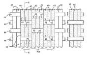
- the electrosurgical system 10includes a deployable electrode device 20 constructed in accordance with the present invention. More particularly, the electrode device 20 , which is carried at the distal end 16 of the catheter 12 , includes a conductive, biocomparable fabric 22 (see also FIG. 3 ) formed into a predetermined shape and defining an outer layer 24 of the electrode device 20 .
- the conductive fabric 22has a plurality of surface electrodes 26 , 28 formed as an integral part thereof for transmitting radio frequency (RF) energy to body tissues.
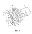
- the electrodes 26are connected to a common lead wire 30 (see FIG. 4 ), which in turn is connected to an external RF energy source 32 (see FIG. 1 ), while the electrodes 28 are connected to a common ground wire 34 (see FIG. 4 ) such that RF energy can be transmitted from the electrodes 26 to the electrodes 28 .
- RFradio frequency
- the conductive fabric 22is formed into a shape or geometry suitable for introduction into a body cavity or conduit (e.g., the atrial chamber of a heart, a uterine cavity, etc.) for ablating tissue therein.
- a body cavity or conduite.g., the atrial chamber of a heart, a uterine cavity, etc.
- the conductive fabric 22can be formed into a generally cylindrical or tubular shape (see FIG. 2A ) having a suitable size (e.g., about 5 cm in length and about 100 microns in wall thickness).
- the conductive fabric 22is preferably elastic such that it is expandable in a generally radial direction from a collapsed configuration (see FIG.
- the conductive fabric 22is sized and shaped such that it fits in the body cavity or conduit in which the electrode device 20 is placed for performing tissue ablation.
- the conductive fabric 22which has an outer surface 36 and an inner surface 38 , is made from electrically conductive warp yarns 40 and electrically nonconductive warp yarns 42 woven with nonconductive fill yarns 44 in a conventional manner.
- the conductive and nonconductive warp yarns 40 , 42extend in a lengthwise direction of the conductive fabric 22
- the nonconductive fill yarns 44extend in a widthwise direction of the conductive fabric 22 .
- the warp yarns 40 , 42are interwoven with the fill yarns 44 such that segments 46 (see FIGS.
- the conductive warp yarns 40are exposed in desired patterns and/or shapes on the outer surface 36 of the conductive fabric 22 .
- the exposed segments 46 of the conductive warp yarns 40define the electrodes 26 , 28 of the electrode device 20 , each of which is hence an integral, woven part of the conductive fabric 22 .
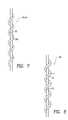
- each of the nonconductive warp and fill yarns 42 , 44can be made by helically winding a reinforcement strand 48 (see FIG. 7 ) about an elastic strand 50 such that the nonconductive yarns 42 , 44 are stretchable in an axial direction.
- the reinforcement strands 48are provided to reinforce the elastic strands 50 and to limit excessive expansion of the elastic strands 50 .
- the reinforcement strands 48 of the nonconductive yarns 42 , 44can be made from any suitable conventional natural materials (e.g., silk, cotton, etc.) or synthetic materials (e.g., polyester, nylon, polypropylene, polyethylene, etc.) and can be provided with any suitable size (e.g., 10-200 denier).
- the elastic strands 50 of the nonconductive yarns 42 , 44can be made from any suitable conventional materials which offer good durability, elasticity and abrasion resistance (e.g., spandex, hytrlel, rubber, etc.).
- the elastic strands 50can also be provided with any suitable size (e.g., a 70 denier strand).
- each nonconductive yarn 42 , 44includes a 50 denier polyester strand 48 wrapped or coiled helically around a 70 denier spandex strand 50 .
- the elasticity of the nonconductive warp and fill yarns 42 , 44is determined by the number of turns of each reinforcement strand 48 per inch of the corresponding elastic yarn 50 (i.e., turns per inch or “tpi”). While any suitable turns per inch can be used for making the nonconductive warp and fill yarns 42 , 44 , the nonconductive yarns 42 , 44 are provided with preferably about 15-20 tpi, and more preferably about 18 tpi.
- each of the conductive warp yarns 40can include a reinforcement strand 52 and an electrically conductive strand or ribbon 54 , both of which are helically wound about an elastic strand 56 (see FIG. 8 ).
- the reinforcement strands 52are provided to reinforce the elastic strands 56 and to limit excessive expansion of the elastic strands 56 .
- the conductive strands 54 wrapping around the elastic strands 56provide the conductive warp yarns 40 with a good electric conducting property.
- the conductive strands 54 of the conductive warp yarns 40can be made from any suitable electrically conductive materials (e.g., gold, silver, platinum, titanium, Pt—Ir, etc.), while the reinforcement strands 52 of the conductive warp yarns 40 can be made from any suitable natural or synthetic materials, such as cotton, silk, polyester, nylon, polypropylene, etc.
- the conductive strands 54 and the reinforcement strands 52can be provided with any suitable sizes.
- the conductive strands 54can have a thickness preferably ranging from about 10 microns to about 100 microns and more preferably of about 50 microns, while the reinforcement strands 52 can be provided with a size of approximately 10-200 denier and, more preferably, about 50 denier.
- each conductive warp yarn 40includes a 50 denier polyester strand 52 and a 10 micron metallic strand. 54 wrapped or coiled around a 70 denier spandex strand 56 .
- the elasticity of the conductive warp yarns 40is determined by the number of turns of the reinforcement and conductive strands 52 , 54 per inch of the corresponding elastic yarn 56 (i.e., turns per inch or “tpi”). While any suitable turns per inch can be used for making the conductive warp yarns 40 , the conductive yarns 40 can be provided with preferably about 15-20 tpi, and more preferably about 18 tpi.
- the conductive and nonconductive warp yarns 40 , 42are interwoven with the nonconductive fill yarns 44 such that the exposed segments 46 of the conductive warp yarns 40 form the electrodes 26 , 28 of the electrode device 20 .
- Any conventional weaving methode.g., tabby weaving methods, jacquard weave methods and methods utilized in the textile industry for making fabrics patterned with metal strands such as bullion emblems and Indian zari sarees
- each of the electrodes 26 , 28is formed by a set of the conductive warp yarns 40 passing under one and over two or more nonconductive fill yarns 44 (see FIGS. 5 and 6 ) such that the conductive warp yarns 40 are exposed to the outer surface 36 of the conductive fabric 22 to a greater extent than the nonconductive fill yarns 44 , forming the electrodes 26 , 28 (i.e., the electrodes 26 , 28 are formed by the exposed conductive yarn segments 46 ).
- Other conventional methods utilized in the textile industry for forming desired fabric patterns and shapese.g., a knitting method
- the warp and fill yarns 40 , 42 , 44are interwoven together such that the conductive fabric 22 is provided with any suitable weave density, and thickness, so long as the structure and functionality of the electrode device 20 is not compromised.
- the conductive fabric 22can be provided with a warp count ranging from about 180 picks per inch to about 300 picks per inch, while the fill count of the conductive fabric 22 can range preferably from about 30 picks per inch to about 70 picks per inch. More preferably, the conductive fabric 22 can be provided with a warp count of about 240 picks per inch and a fill count of about 50 picks per inch.
- the electrodes 26are electrically wired to the common lead wire 30 , which in turn is connected to the RF energy source 32 (see FIG. 1 ), while the electrodes 28 are connected to the common ground wire 34 such that RF energy can be transmitted from the electrodes 26 to the electrodes 28 .
- each set or array of the electrodes 26 , 28is formed by a common set of conductive warp yarns 40 (e.g., the electrodes 26 a arranged in row A in FIGS. 2A and 4 are formed by a set of conductive warp yarns 40 a in FIG. 5 ), the electrodes 26 , 28 in each array are electrically connected to one another. As a result, only one wiring connection is required for each electrode array to electrically connect same to the common lead wire 30 or the common ground wire 34 .
- a set of the conductive warp yarns 40forms a corresponding array of the electrodes 26 , 28 .
- the nonconductive warp yarns 42are interwoven together with the nonconductive fill yarns 44 between each adjacent pair of electrode arrays (see FIG. 5 ).
- the inner surface 38 of the conductive fabric 22can also be coated with an electrically insulating material 58 for electrical insulation of non-exposed segments of the conductive warp yarns 40 .
- the electrode device 20is provided with a balloon 60 (see FIGS. 2A , 4 and 9 ) connected to the distal end 16 of the catheter 12 .
- the balloon 60which is mounted within the conductive fabric 22 , has a construction and operation similar to those of a balloon of a conventional catheter (e.g., the inflatable balloons disclosed in U.S. Pat. Nos. 5,891,136 and 6,231,572, the disclosures of which are incorporated herein by reference in their entirety).
- fluide.g., a saline solution
- the balloon 60expands radially outwardly, thereby causing the conductive fabric 22 to assume its expanded configuration from its collapsed configuration.
- other types of expanding mechanismscan be utilized instead of the balloon 60 .
- the electrode device 20is delivered into the body of a patient to the treatment site 62 in its collapsed configuration using a conventional method.
- a guide wire and a sheathcan be use to deliver the electrode device 20 to the treatment site 62 .
- the balloon 60is expanded by introducing fluid thereinto, causing the electrode device 20 to assume its expanded configuration.
- RF energyis then applied from the RF energy source 32 so as to perform ablation of tissues at the treatment site 62 .
- the fluid contained in the balloon 60is withdrawn, thereby causing the electrode device 20 to contract to its collapsed configuration for withdrawal of same from the treatment site 62 .
- the present inventionprovides numerous advantages over the prior art discussed above.
- the electrodes 26 , 28are formed as integrated part of the conductive fabric 22 , they are flexible and adapted for easy deployment at a treatment site.
- the electrodes 26 , 28can be easily shaped and patterned on the conductive fabric 22 in any desired manner.
- FIGS. 13 and 14illustrate alternate electrode shapes and patterns (represented therein by the dark areas 64 ) which can be formed easily and cost-effectively. In such circumstances, it is possible to make electrodes having complex patterns/shapes and having large coverage areas.
- the electrodes 26 , 28can therefore be patterned such that the entire RF energy passing between the electrodes 26 , 28 is focused substantially on the lesion area, thereby protecting healthy tissues.
- wiring of the electrodes 26 , 28 to the RF energy source 32is rendered relatively simple. That is, only one wiring connection is required to power all electrodes 26 , 28 formed by the same set of the conductive yarns 40 .
- the electrode device 20can be provided with a different mechanism for expanding the conductive fabric 22 from its collapsed configuration to its expanded configuration.
- the electrode device 20can be equipped with the flexible spine element/sheath arrangement disclosed in U.S. Pat. No. 5,891,136.
- the conductive fabric 22can also be constructed such that it is fluid-tight. In such an embodiment, the conductive fabric 22 can functions as a balloon, thereby eliminating the need to provide a separate balloon structure.
- the conductive fabric 22can also be modified in numerous ways.
- the elastic strands 50 , 56 of the warp yarns 42 , 40can be textured strands to provide same with elasticity.
- the warp yarns 42 , 40can be made without the elastic strands 50 , 56 , respectively, such that only the fill yarns 44 are elastic.
- the conductive fabric 22which is in a tubular shape, is expandable only in a radial direction (i.e., the conductive fabric 22 is not expandable in an axial direction). All of the warp yarns 40 , 42 and the fill yarns 44 can also be made without the elastic strands 50 , 56 such that the entire conductive fabric 22 is substantially non-elastic.
- the conductive fabric 22can be provided with a pleated or folded construction such that it can expand from its folded configuration to its expanded configuration.
- the conductive fabric 22can also be formed into a different shape, depending upon the requirements/needs of the electrode device 20 .
- the conductive fabric 22can be formed into an oblong shape and can expand from a collapsed configuration (see FIG. 11 ) to an expanded configuration (see FIG. 12 ).
- the conductive fabric 22can also be made using processes other than weaving methods.
- the conductive fabric 22can be formed as a knitted fabric.
- the electrode device 20 of the present inventioncan be bipolar or monopolar. When used as a monopolar device, all of the electrodes 26 , 28 formed on the conductive fabric 22 are wired to the common lead wire 30 for being powered by the RF energy source 32 .
- each conductive yarn 40can be formed entirely of flexible metallic filaments which are twisted with each other.
- each conductive yarn 40can be formed as a single conductive filament, thread, ribbon or wire. Accordingly, as used herein, the term “yarn” shall denote to include a composite yarn which are made from multiple filaments or threads, as well as a yarn which is constructed entirely of a single filament, thread, ribbon or wire.
- the conductive yarns 40can also be formed by a nonconductive yarn deposited or coated with conductive materials.
- the conductive yarns 40can also be formed of three components (i.e., a metallic alloy wire, a silk thread and a gold coating) which are integrated together by a conventional spinning and gilding process to make Indian zari sarees.
- the metallic wirecan be made from silver and copper in a desired composition (e.g., 77% silver and 23% copper) and is flattened to a suitable size (e.g., 25 microns in thickness).
- the silk threadcan form the core over which the flattened metallic wire can be wound.
- the uncoated metallic wirecan then be coated with a gold coating by using a conventional electroplating process to give uniform covering with a desired overall gold content (e.g., 0.59%-0.60%).
- the present inventioncan also be used in connection with other medical devices requiring the use of electrodes.
- the electrode device 20 of the present inventioncan be used in conjunction with other surgical instruments.
- the electrode device 20 of the present inventioncan be used in a device for monitoring electrical signals generated by organs or body tissues (e.g., for sensing electrical activity in a heart).
- the conductive fabric 22can be permanently attached to the balloon 60 .
- the conductive fabric 22can be removably attached to the balloon 60 . In this manner, the conductive fabric 22 can be removed easily from the balloon 60 for disposal and/or replacement with another conductive fabric.
Landscapes
- Health & Medical Sciences (AREA)
- Life Sciences & Earth Sciences (AREA)
- Surgery (AREA)
- Engineering & Computer Science (AREA)
- Plasma & Fusion (AREA)
- Medical Informatics (AREA)
- Otolaryngology (AREA)
- Physics & Mathematics (AREA)
- Cardiology (AREA)
- Biomedical Technology (AREA)
- Heart & Thoracic Surgery (AREA)
- Nuclear Medicine, Radiotherapy & Molecular Imaging (AREA)
- Molecular Biology (AREA)
- Animal Behavior & Ethology (AREA)
- General Health & Medical Sciences (AREA)
- Public Health (AREA)
- Veterinary Medicine (AREA)
- Surgical Instruments (AREA)
Abstract
Description
The invention relates to medical devices and, more particularly, surgical devices having a flexible, fabric-woven surface electrode structure.
Surgical devices have been in use for performing electrosurgical ablation of body tissues. This type of surgical device utilizes electrosurgical energy (e.g., radio frequency (RF) energy) passed between a pair of electrodes to create a high current density which ablate the body tissues.
Efforts have been made in the past to develop flexible electrodes that can be deployed easily at a treatment site. For instance, U.S. Pat. No. 5,891,136 discloses an RF surgical device having an expandable/collapsible electrode structure. While at least some portions of this electrode structure are flexible, it requires a fairly complicated process for forming electrodes thereon and for electrically connecting the electrodes to an external RF energy source.
U.S. Pat. No. 6,231,572 discloses an electrosurgical catheter apparatus having a solid metal electrode which is mounted on an inflatable balloon. While the balloon is expandable for deploying the electrode at a treatment site, the electrode is relatively rigid.
Fabrics patterned with metal strands (e.g., Indian zari sarees and fabrics with bullion emblems) have been available. However, such fabrics are not specifically suitable for medical use.
In the foregoing circumstances, there is a need for an electrosurgical apparatus having flexible electrodes that can be easily deployed at a treatment site and that can be manufactured in a simple, cost-effective manner.
The present invention overcomes the disadvantages and shortcomings of the prior art discussed above by providing a new and improved electrode device adapted for use in medical apparatus. More particularly, the electrode device includes a sheet of flexible fabric including at least one surface electrode formed as part of the fabric. The sheet is made from a plurality of filaments. At least some of the filaments are made at least partially from an electrically conductive material and cooperate so as to form the electrode. The filaments are formed into a plurality of yarns which are interwoven to form the sheet.
In accordance with another aspect of the present invention, a tissue ablation device is provided. More particularly, the tissue ablation device includes a sheet of flexible fabric including at least one surface electrode formed as part of the fabric. The sheet is made from a plurality of interwoven yarns. At least some of the yarns are made at least partially from an electrically conductive material and cooperate so as to define the electrode. The yarns include a plurality of warp yarns and a plurality of full yarns.
In accordance with yet another aspect of the present invention, a method for making an electrode device adapted for use in medical devices is provided. The method includes the step of providing a plurality of yarns, at least some of which are electrically conductive. A sheet of fabric is formed with the yarns such that at least some of the yarns form at least one electrode. The sheet is then shaped into a predetermined shape.
For a more complete understanding of the present invention, reference is made to the following detailed description of an exemplary embodiment considered in conjunction with the accompanying drawings, in which:
Although the present invention can be used for many different types of medical devices, it is particularly suitable for use in connection with a tissue ablation device utilizing radio frequency (RF) energy. Accordingly, the present invention will be described hereinafter in connection with such a tissue ablation device. It should be understood, however, that the following description is only meant to be illustrative of the present invention and is not meant to limit the scope of the present invention, which has applicability to other types of medical devices.
With reference toFIGS. 1 and 2A , theelectrosurgical system 10 includes adeployable electrode device 20 constructed in accordance with the present invention. More particularly, theelectrode device 20, which is carried at thedistal end 16 of thecatheter 12, includes a conductive, biocomparable fabric22 (see alsoFIG. 3 ) formed into a predetermined shape and defining anouter layer 24 of theelectrode device 20. Theconductive fabric 22 has a plurality ofsurface electrodes electrodes 26 are connected to a common lead wire30 (seeFIG. 4 ), which in turn is connected to an external RF energy source32 (seeFIG. 1 ), while theelectrodes 28 are connected to a common ground wire34 (seeFIG. 4 ) such that RF energy can be transmitted from theelectrodes 26 to theelectrodes 28.
Theconductive fabric 22 is formed into a shape or geometry suitable for introduction into a body cavity or conduit (e.g., the atrial chamber of a heart, a uterine cavity, etc.) for ablating tissue therein. For instance, theconductive fabric 22 can be formed into a generally cylindrical or tubular shape (seeFIG. 2A ) having a suitable size (e.g., about 5 cm in length and about 100 microns in wall thickness). Theconductive fabric 22 is preferably elastic such that it is expandable in a generally radial direction from a collapsed configuration (seeFIG. 2B ), in which it has a sufficiently small diameter or size (e.g., about ¼″ in diameter) so as to permit its placement at a desired treatment site in the body of a patient, and an expanded configuration (seeFIG. 2A ), in which it has a sufficiently large diameter or size (e.g., about 3 inches in diameter) so as to permit efficient tissue ablation. When expanded into its expanded configuration, theconductive fabric 22 is sized and shaped such that it fits in the body cavity or conduit in which theelectrode device 20 is placed for performing tissue ablation.
With reference toFIGS. 2A ,5 and6, theconductive fabric 22, which has anouter surface 36 and aninner surface 38, is made from electricallyconductive warp yarns 40 and electricallynonconductive warp yarns 42 woven withnonconductive fill yarns 44 in a conventional manner. The conductive andnonconductive warp yarns conductive fabric 22, while thenonconductive fill yarns 44 extend in a widthwise direction of theconductive fabric 22. As will be discussed in greater detail hereinbelow, thewarp yarns fill yarns 44 such that segments46 (seeFIGS. 5 and 6 ) of theconductive warp yarns 40 are exposed in desired patterns and/or shapes on theouter surface 36 of theconductive fabric 22. The exposedsegments 46 of theconductive warp yarns 40 define theelectrodes electrode device 20, each of which is hence an integral, woven part of theconductive fabric 22.
Now referring toFIG. 5 , while the conductive andnonconductive yarns conductive fabric 22 with sufficient elasticity (i.e., to permit expansion and contraction between its collapsed and expanded configurations), they are preferably made to be elastic. For instance, each of the nonconductive warp and fillyarns FIG. 7 ) about anelastic strand 50 such that thenonconductive yarns reinforcement strands 48 are provided to reinforce theelastic strands 50 and to limit excessive expansion of theelastic strands 50.
Thereinforcement strands 48 of thenonconductive yarns elastic strands 50 of thenonconductive yarns elastic strands 50 can also be provided with any suitable size (e.g., a 70 denier strand). In one embodiment of the present invention, eachnonconductive yarn denier polyester strand 48 wrapped or coiled helically around a 70denier spandex strand 50.
The elasticity of the nonconductive warp and fillyarns reinforcement strand 48 per inch of the corresponding elastic yarn50 (i.e., turns per inch or “tpi”). While any suitable turns per inch can be used for making the nonconductive warp and fillyarns nonconductive yarns
Like the nonconductive warp and fillyarns conductive warp yarns 40 are made to be elastic so as to provide theconductive fabric 22 with sufficient elasticity. More particularly, each of theconductive warp yarns 40 can include areinforcement strand 52 and an electrically conductive strand orribbon 54, both of which are helically wound about an elastic strand56 (seeFIG. 8 ). Thereinforcement strands 52 are provided to reinforce theelastic strands 56 and to limit excessive expansion of theelastic strands 56. Theconductive strands 54 wrapping around theelastic strands 56 provide theconductive warp yarns 40 with a good electric conducting property.
Theconductive strands 54 of theconductive warp yarns 40 can be made from any suitable electrically conductive materials (e.g., gold, silver, platinum, titanium, Pt—Ir, etc.), while thereinforcement strands 52 of theconductive warp yarns 40 can be made from any suitable natural or synthetic materials, such as cotton, silk, polyester, nylon, polypropylene, etc. Theconductive strands 54 and thereinforcement strands 52 can be provided with any suitable sizes. For instance, theconductive strands 54 can have a thickness preferably ranging from about 10 microns to about 100 microns and more preferably of about 50 microns, while thereinforcement strands 52 can be provided with a size of approximately 10-200 denier and, more preferably, about 50 denier. Likewise, theelastic strands 56 of theconductive warp yarns 40 can be made from any suitable conventional materials which offer good durability, elasticity and abrasion resistance (e.g., spandex, hytrel, rubber, etc.). Theelastic strands 56 can also be provided with any suitable size (e.g., a 70 denier strand). In one embodiment of the present invention, eachconductive warp yarn 40 includes a 50denier polyester strand 52 and a 10 micron metallic strand.54 wrapped or coiled around a 70denier spandex strand 56.
Like the nonconductive warp and fillyarns conductive warp yarns 40 is determined by the number of turns of the reinforcement andconductive strands conductive warp yarns 40, theconductive yarns 40 can be provided with preferably about 15-20 tpi, and more preferably about 18 tpi.
The conductive andnonconductive warp yarns nonconductive fill yarns 44 such that the exposedsegments 46 of theconductive warp yarns 40 form theelectrodes electrode device 20. Any conventional weaving method (e.g., tabby weaving methods, jacquard weave methods and methods utilized in the textile industry for making fabrics patterned with metal strands such as bullion emblems and Indian zari sarees) can be utilized for making theconductive fabric 22 using thewarp yarns fill yarns 44 and for shaping and/or patterning theelectrodes outer surface 36 of theconductive fabric 22. For instance, a conventional uneven twill weaving method can be used for making theconductive fabric 22 and patterning thesurface electrodes electrodes conductive warp yarns 40 passing under one and over two or more nonconductive fill yarns44 (seeFIGS. 5 and 6 ) such that theconductive warp yarns 40 are exposed to theouter surface 36 of theconductive fabric 22 to a greater extent than thenonconductive fill yarns 44, forming theelectrodes 26,28 (i.e., theelectrodes conductive fabric 22.
The warp and fillyarns conductive fabric 22 is provided with any suitable weave density, and thickness, so long as the structure and functionality of theelectrode device 20 is not compromised. For instance, theconductive fabric 22 can be provided with a warp count ranging from about 180 picks per inch to about 300 picks per inch, while the fill count of theconductive fabric 22 can range preferably from about 30 picks per inch to about 70 picks per inch. More preferably, theconductive fabric 22 can be provided with a warp count of about 240 picks per inch and a fill count of about 50 picks per inch.
With reference toFIG. 4 , theelectrodes 26 are electrically wired to thecommon lead wire 30, which in turn is connected to the RF energy source32 (seeFIG. 1 ), while theelectrodes 28 are connected to thecommon ground wire 34 such that RF energy can be transmitted from theelectrodes 26 to theelectrodes 28. More particularly, because each set or array of theelectrodes electrodes 26aarranged in row A inFIGS. 2A and 4 are formed by a set ofconductive warp yarns 40ainFIG. 5 ), theelectrodes common lead wire 30 or thecommon ground wire 34.
With reference toFIGS. 4-6 , as discussed above, a set of theconductive warp yarns 40 forms a corresponding array of theelectrodes electrodes nonconductive warp yarns 42 are interwoven together with thenonconductive fill yarns 44 between each adjacent pair of electrode arrays (seeFIG. 5 ). Theinner surface 38 of theconductive fabric 22 can also be coated with an electrically insulatingmaterial 58 for electrical insulation of non-exposed segments of theconductive warp yarns 40.
In order to expand theconductive fabric 22 from its collapsed configuration to its expanded configuration, theelectrode device 20 is provided with a balloon60 (seeFIGS. 2A ,4 and9) connected to thedistal end 16 of thecatheter 12. Theballoon 60, which is mounted within theconductive fabric 22, has a construction and operation similar to those of a balloon of a conventional catheter (e.g., the inflatable balloons disclosed in U.S. Pat. Nos. 5,891,136 and 6,231,572, the disclosures of which are incorporated herein by reference in their entirety). For instance, when fluid (e.g., a saline solution) is injected into theballoon 60 through the lumen of thecatheter 12, theballoon 60 expands radially outwardly, thereby causing theconductive fabric 22 to assume its expanded configuration from its collapsed configuration. Alternatively, other types of expanding mechanisms can be utilized instead of theballoon 60.
With reference toFIG. 10 , in order to perform tissue ablation at a treatment site62 (e.g., the atrial chamber of a heart, a uterine cavity, etc.), theelectrode device 20 is delivered into the body of a patient to thetreatment site 62 in its collapsed configuration using a conventional method. For instance, a guide wire and a sheath (not shown) can be use to deliver theelectrode device 20 to thetreatment site 62. After properly positioning theelectrode device 20 at thetreatment site 62, theballoon 60 is expanded by introducing fluid thereinto, causing theelectrode device 20 to assume its expanded configuration. RF energy is then applied from theRF energy source 32 so as to perform ablation of tissues at thetreatment site 62. After the performance of the tissue ablation, the fluid contained in theballoon 60 is withdrawn, thereby causing theelectrode device 20 to contract to its collapsed configuration for withdrawal of same from thetreatment site 62.
It should be appreciated that the present invention provides numerous advantages over the prior art discussed above. For instance, because theelectrodes conductive fabric 22, they are flexible and adapted for easy deployment at a treatment site. Moreover, with the use of a conventional fabric manufacturing process, theelectrodes conductive fabric 22 in any desired manner. For example,FIGS. 13 and 14 illustrate alternate electrode shapes and patterns (represented therein by the dark areas64) which can be formed easily and cost-effectively. In such circumstances, it is possible to make electrodes having complex patterns/shapes and having large coverage areas. Theelectrodes electrodes
Because theelectrodes conductive warp yarns 40 are electrically connected to each other, wiring of theelectrodes RF energy source 32 is rendered relatively simple. That is, only one wiring connection is required to power allelectrodes conductive yarns 40.
It should be noted that the present invention can have numerous modifications and variations. For instance, theelectrode device 20 can be provided with a different mechanism for expanding theconductive fabric 22 from its collapsed configuration to its expanded configuration. By way of example, theelectrode device 20 can be equipped with the flexible spine element/sheath arrangement disclosed in U.S. Pat. No. 5,891,136. Theconductive fabric 22 can also be constructed such that it is fluid-tight. In such an embodiment, theconductive fabric 22 can functions as a balloon, thereby eliminating the need to provide a separate balloon structure.
Theconductive fabric 22 can also be modified in numerous ways. For instance, theelastic strands warp yarns warp yarns elastic strands fill yarns 44 are elastic. In such circumstances, theconductive fabric 22, which is in a tubular shape, is expandable only in a radial direction (i.e., theconductive fabric 22 is not expandable in an axial direction). All of thewarp yarns fill yarns 44 can also be made without theelastic strands conductive fabric 22 is substantially non-elastic. In this configuration, theconductive fabric 22 can be provided with a pleated or folded construction such that it can expand from its folded configuration to its expanded configuration.
Theconductive fabric 22 can also be formed into a different shape, depending upon the requirements/needs of theelectrode device 20. For instance, theconductive fabric 22 can be formed into an oblong shape and can expand from a collapsed configuration (seeFIG. 11 ) to an expanded configuration (seeFIG. 12 ). Theconductive fabric 22 can also be made using processes other than weaving methods. For example, theconductive fabric 22 can be formed as a knitted fabric.
Theelectrode device 20 of the present invention can be bipolar or monopolar. When used as a monopolar device, all of theelectrodes conductive fabric 22 are wired to thecommon lead wire 30 for being powered by theRF energy source 32.
Theconductive warp yarns 40 can also be modified in numerous ways. For instance, eachconductive yarn 40 can be formed entirely of flexible metallic filaments which are twisted with each other. Moreover, eachconductive yarn 40 can be formed as a single conductive filament, thread, ribbon or wire. Accordingly, as used herein, the term “yarn” shall denote to include a composite yarn which are made from multiple filaments or threads, as well as a yarn which is constructed entirely of a single filament, thread, ribbon or wire. Theconductive yarns 40 can also be formed by a nonconductive yarn deposited or coated with conductive materials.
Theconductive yarns 40 can also be formed of three components (i.e., a metallic alloy wire, a silk thread and a gold coating) which are integrated together by a conventional spinning and gilding process to make Indian zari sarees. More particularly, the metallic wire can be made from silver and copper in a desired composition (e.g., 77% silver and 23% copper) and is flattened to a suitable size (e.g., 25 microns in thickness). The silk thread can form the core over which the flattened metallic wire can be wound. The uncoated metallic wire can then be coated with a gold coating by using a conventional electroplating process to give uniform covering with a desired overall gold content (e.g., 0.59%-0.60%).
The present invention can also be used in connection with other medical devices requiring the use of electrodes. For instance, theelectrode device 20 of the present invention can be used in conjunction with other surgical instruments. Moreover, theelectrode device 20 of the present invention can be used in a device for monitoring electrical signals generated by organs or body tissues (e.g., for sensing electrical activity in a heart).
Theconductive fabric 22 can be permanently attached to theballoon 60. Alternatively, theconductive fabric 22 can be removably attached to theballoon 60. In this manner, theconductive fabric 22 can be removed easily from theballoon 60 for disposal and/or replacement with another conductive fabric.
It will be understood that the embodiments described herein are merely exemplary and that a person skilled in the art may make many variations and modifications without departing from the spirit and scope of the invention. All such variations and modifications, including those discussed hereinabove, are intended to be included within the scope of the invention as defined in the appended claims.
Claims (16)
1. An electrode device adapted for use in medical devices, comprising a sheet of flexible fabric including a plurality of electrodes formed as part of said sheet, said sheet having inner and outer sides and being made from a plurality of yarns including first and second yarns, each of which is electrically non-conductive, and third yarns, each of which is electrically conductive, said first yarns extending in a first direction, said second and third yarns extending in a second direction which is different from said first direction, each of said third yarns including a plurality of segments exposed to said outer side of said sheet, said segments of said third yarns being arranged into groups, said segments of each of said groups being arranged side-by-side so as to form a corresponding one of said electrodes as part of said outer side of said sheet, each of said groups being separated from an adjacent one of said groups in said first direction by a set of said second yarns, and each of said groups being separated from an adjacent one of said groups in said second direction by a set of said first yarns.
2. The electrode device ofclaim 1 , wherein said first yarns include a plurality of fill yarns, said second and third yarns including a plurality of warp yarns.
3. The electrode device ofclaim 1 , wherein each of said first, second and third yarns is elastic so as to provide elasticity to said sheet.
4. The electrode device ofclaim 3 , wherein each of said third yarns includes an electrically conductive strand, a reinforcement strand and an elastic strand, said conductive strand and said reinforcement strand of each of said third yarns being wound around a corresponding one of said elastic strands of said third yarns.
5. The electrode device ofclaim 4 , wherein each of said first and second yarns includes an elastic strand and a reinforcement strand, said reinforcement strand of each of said first and second yarns being wound around a corresponding one of said elastic strands of said first and second yarns.
6. The electrode device ofclaim 1 , wherein said sheet is formed into a first shape, said sheet being expandable from said first shape to a second shape, said sheet being contractible from said second shape to said first shape.
7. The electrode device ofclaim 6 , further comprising expanding means for expanding said sheet from said first shape to said second shape.
8. The electrode device ofclaim 7 , wherein said expanding means includes an expandable balloon, said sheet being attached to said balloon such that said sheet expands from said first shape to said second shape when fluid is injected into said balloon, said sheet contracting from said second shape to said first shape when the fluid is permitted to evacuate from said balloon.
9. A tissue ablation device comprising a sheet of flexible fabric including a plurality of electrodes formed as part of said sheet, said sheet having inner and outer sides and being made from a plurality of yarns including first and second yarns, each of which is electrically non-conductive, and third yarns, each of which is electrically conductive, said first yarns extending in a first direction, said second and third yarns extending in a second direction which is different from said first direction, each of said third yarns including a plurality of segments exposed to said outer side of said sheet, said segments of said third yarns being arranged into groups, said segments of each of said groups being arranged side-by-side so as to form a corresponding one of said electrodes as part of said outer side of said sheet, each of said groups being separated from an adjacent one of said groups in said first direction by a set of said second yarns, and each of said groups being separated from an adjacent one of said groups in said second direction by a set of said first yarns.
10. The tissue ablation device ofclaim 9 , wherein said first yarns include a plurality of fill yarns; and wherein said second and third yarns include a plurality of warp yarns.
11. The tissue ablation device ofclaim 9 , wherein each of said first, second and third yarns is elastic so as to provide elasticity to said sheet.
12. The tissue ablation device ofclaim 11 , wherein each of said third yarns includes an electrically conductive strand, a reinforcement strand and an elastic strand, said conductive strand and said reinforcement strand of each of said third yarns being wound around a corresponding one of said elastic strands of said third yarns.
13. The tissue ablation device ofclaim 12 , wherein each of said first and second yarns includes an elastic strand and a reinforcement strand, said reinforcement strand of each of said first and second yarns being wound around a corresponding one of said elastic strands of said first and second yarns.
14. The tissue ablation device ofclaim 11 , wherein said sheet is formed into a first shape, said sheet being expandable from said first shape to a second shape, said sheet being contractible from said second shape to said first shape.
15. The tissue ablation device ofclaim 14 , further comprising expanding means for expanding said sheet from said first shape to said second shape.
16. The tissue ablation device ofclaim 15 , wherein said expanding means includes an expandable balloon, said sheet being attached to said balloon such that said sheet expands from said first shape to said second shape when fluid is injected into said balloon, said sheet contracting from said second shape to said first shape when the fluid is permitted to evacuate from said balloon.
Priority Applications (1)
| Application Number | Priority Date | Filing Date | Title |
|---|---|---|---|
| US10/881,692US7481808B2 (en) | 2004-06-30 | 2004-06-30 | Flexible electrode device and surgical apparatus equipped with same |
Applications Claiming Priority (1)
| Application Number | Priority Date | Filing Date | Title |
|---|---|---|---|
| US10/881,692US7481808B2 (en) | 2004-06-30 | 2004-06-30 | Flexible electrode device and surgical apparatus equipped with same |
Publications (2)
| Publication Number | Publication Date |
|---|---|
| US20060004353A1 US20060004353A1 (en) | 2006-01-05 |
| US7481808B2true US7481808B2 (en) | 2009-01-27 |
Family
ID=35514985
Family Applications (1)
| Application Number | Title | Priority Date | Filing Date |
|---|---|---|---|
| US10/881,692Active2026-07-08US7481808B2 (en) | 2004-06-30 | 2004-06-30 | Flexible electrode device and surgical apparatus equipped with same |
Country Status (1)
| Country | Link |
|---|---|
| US (1) | US7481808B2 (en) |
Cited By (42)
| Publication number | Priority date | Publication date | Assignee | Title |
|---|---|---|---|---|
| US20080147155A1 (en)* | 2006-12-19 | 2008-06-19 | Quan Emerteq Corp. | Braided Electrical Lead |
| US20090248019A1 (en)* | 2008-03-31 | 2009-10-01 | Applied Medical Resources Corporation | Electrosurgical system |
| US20100204560A1 (en)* | 2008-11-11 | 2010-08-12 | Amr Salahieh | Low profile electrode assembly |
| US20100331776A1 (en)* | 2009-06-24 | 2010-12-30 | Amr Salahieh | Steerable Medical Delivery Devices and Methods of Use |
| US20110138938A1 (en)* | 2005-09-08 | 2011-06-16 | Giszter Simon F | Sensing probe comprising multiple, spatially separate, sensing sites |
| US20130197513A1 (en)* | 2011-01-21 | 2013-08-01 | Kardium Inc. | High-density electrode-based medical device system |
| US8708953B2 (en) | 2009-06-24 | 2014-04-29 | Shifamed Holdings, Llc | Steerable medical delivery devices and methods of use |
| US8805466B2 (en) | 2008-11-11 | 2014-08-12 | Shifamed Holdings, Llc | Low profile electrode assembly |
| US8840601B2 (en) | 2010-03-24 | 2014-09-23 | Shifamed Holdings, Llc | Intravascular tissue disruption |
| US8961550B2 (en) | 2012-04-17 | 2015-02-24 | Indian Wells Medical, Inc. | Steerable endoluminal punch |
| USD748259S1 (en) | 2014-12-29 | 2016-01-26 | Applied Medical Resources Corporation | Electrosurgical instrument |
| US9320563B2 (en) | 2010-10-01 | 2016-04-26 | Applied Medical Resources Corporation | Electrosurgical instruments and connections thereto |
| US9333031B2 (en) | 2013-04-08 | 2016-05-10 | Apama Medical, Inc. | Visualization inside an expandable medical device |
| US9452016B2 (en) | 2011-01-21 | 2016-09-27 | Kardium Inc. | Catheter system |
| US9492227B2 (en) | 2011-01-21 | 2016-11-15 | Kardium Inc. | Enhanced medical device for use in bodily cavities, for example an atrium |
| USD777925S1 (en) | 2012-01-20 | 2017-01-31 | Kardium Inc. | Intra-cardiac procedure device |
| USD777926S1 (en) | 2012-01-20 | 2017-01-31 | Kardium Inc. | Intra-cardiac procedure device |
| US9585717B2 (en) | 2007-11-16 | 2017-03-07 | Kardium Inc. | Medical device for use in bodily lumens, for example an atrium |
| US9655677B2 (en) | 2010-05-12 | 2017-05-23 | Shifamed Holdings, Llc | Ablation catheters including a balloon and electrodes |
| US9757193B2 (en) | 2002-04-08 | 2017-09-12 | Medtronic Ardian Luxembourg S.A.R.L. | Balloon catheter apparatus for renal neuromodulation |
| US9795442B2 (en) | 2008-11-11 | 2017-10-24 | Shifamed Holdings, Llc | Ablation catheters |
| US9827040B2 (en) | 2002-04-08 | 2017-11-28 | Medtronic Adrian Luxembourg S.a.r.l. | Methods and apparatus for intravascularly-induced neuromodulation |
| US9919144B2 (en) | 2011-04-08 | 2018-03-20 | Medtronic Adrian Luxembourg S.a.r.l. | Iontophoresis drug delivery system and method for denervation of the renal sympathetic nerve and iontophoretic drug delivery |
| US9987083B2 (en) | 2006-06-28 | 2018-06-05 | Kardium Inc. | Apparatus and method for intra-cardiac mapping and ablation |
| US10028783B2 (en) | 2006-06-28 | 2018-07-24 | Kardium Inc. | Apparatus and method for intra-cardiac mapping and ablation |
| US10098694B2 (en) | 2013-04-08 | 2018-10-16 | Apama Medical, Inc. | Tissue ablation and monitoring thereof |
| US10149713B2 (en) | 2014-05-16 | 2018-12-11 | Applied Medical Resources Corporation | Electrosurgical system |
| US10349824B2 (en) | 2013-04-08 | 2019-07-16 | Apama Medical, Inc. | Tissue mapping and visualization systems |
| US10420603B2 (en) | 2014-12-23 | 2019-09-24 | Applied Medical Resources Corporation | Bipolar electrosurgical sealer and divider |
| US10420537B2 (en) | 2015-03-27 | 2019-09-24 | Shifamed Holdings, Llc | Steerable medical devices, systems, and methods of use |
| US10588682B2 (en) | 2011-04-25 | 2020-03-17 | Medtronic Ardian Luxembourg S.A.R.L. | Apparatus and methods related to constrained deployment of cryogenic balloons for limited cryogenic ablation of vessel walls |
| US10660697B2 (en) | 2009-11-10 | 2020-05-26 | Cardea Medsystems (Tianjin) Co., Ltd. | Hollow body cavity ablation apparatus |
| US10709490B2 (en) | 2014-05-07 | 2020-07-14 | Medtronic Ardian Luxembourg S.A.R.L. | Catheter assemblies comprising a direct heating element for renal neuromodulation and associated systems and methods |
| US10736693B2 (en) | 2015-11-16 | 2020-08-11 | Apama Medical, Inc. | Energy delivery devices |
| US10758303B2 (en) | 2009-11-10 | 2020-09-01 | Cardea Medsystems (Tianjin) Co., Ltd. | Hollow body cavity ablation apparatus |
| US10792092B2 (en) | 2014-05-30 | 2020-10-06 | Applied Medical Resources Corporation | Electrosurgical seal and dissection systems |
| US10933221B2 (en) | 2015-11-09 | 2021-03-02 | Kalila Medical, Inc. | Steering assemblies for medical devices, and methods of use |
| US11052226B2 (en) | 2015-04-24 | 2021-07-06 | Kalila Medical, Inc. | Steerable medical devices, systems, and methods of use |
| US11259867B2 (en) | 2011-01-21 | 2022-03-01 | Kardium Inc. | High-density electrode-based medical device system |
| US11389232B2 (en) | 2006-06-28 | 2022-07-19 | Kardium Inc. | Apparatus and method for intra-cardiac mapping and ablation |
| US11696796B2 (en) | 2018-11-16 | 2023-07-11 | Applied Medical Resources Corporation | Electrosurgical system |
| US11864812B2 (en) | 2018-09-05 | 2024-01-09 | Applied Medical Resources Corporation | Electrosurgical generator control system |
Families Citing this family (24)
| Publication number | Priority date | Publication date | Assignee | Title |
|---|---|---|---|---|
| EP1542587B1 (en) | 2002-08-24 | 2011-04-27 | St. Jude Medical, Atrial Fibrillation Division, Inc. | Method and apparatus for locating the fossa ovalis and performing transseptal puncture |
| US20080161893A1 (en)* | 2006-12-29 | 2008-07-03 | Saurav Paul | Fabric electrode head |
| US8764742B2 (en) | 2007-04-04 | 2014-07-01 | St. Jude Medical, Atrial Fibrillation Division, Inc. | Irrigated catheter |
| US8979837B2 (en)* | 2007-04-04 | 2015-03-17 | St. Jude Medical, Atrial Fibrillation Division, Inc. | Flexible tip catheter with extended fluid lumen |
| US8517999B2 (en) | 2007-04-04 | 2013-08-27 | St. Jude Medical, Atrial Fibrillation Division, Inc. | Irrigated catheter with improved fluid flow |
| US8187267B2 (en)* | 2007-05-23 | 2012-05-29 | St. Jude Medical, Atrial Fibrillation Division, Inc. | Ablation catheter with flexible tip and methods of making the same |
| US8974454B2 (en) | 2009-12-31 | 2015-03-10 | St. Jude Medical, Atrial Fibrillation Division, Inc. | Kit for non-invasive electrophysiology procedures and method of its use |
| US11395694B2 (en)* | 2009-05-07 | 2022-07-26 | St. Jude Medical, Llc | Irrigated ablation catheter with multiple segmented ablation electrodes |
| US8734440B2 (en)* | 2007-07-03 | 2014-05-27 | St. Jude Medical, Atrial Fibrillation Division, Inc. | Magnetically guided catheter |
| US10220187B2 (en) | 2010-06-16 | 2019-03-05 | St. Jude Medical, Llc | Ablation catheter having flexible tip with multiple flexible electrode segments |
| EP2173426B1 (en) | 2007-07-03 | 2016-04-20 | Irvine Biomedical, Inc. | Magnetically guided catheter |
| US8128617B2 (en)* | 2008-05-27 | 2012-03-06 | Boston Scientific Scimed, Inc. | Electrical mapping and cryo ablating with a balloon catheter |
| CA2758118C (en) | 2009-04-07 | 2019-05-21 | Catholic Healthcare West | Uterine electrical stimulation system and method |
| US9872983B2 (en) | 2010-10-27 | 2018-01-23 | Dignity Health | Uterine electrical stimulation system and method |
| EP3378391B1 (en) | 2010-10-27 | 2020-12-02 | Dignity Health | Uterine electrical stimulation system |
| US8998893B2 (en)* | 2010-12-07 | 2015-04-07 | Boaz Avitall | Catheter systems for cardiac arrhythmia ablation |
| US9968300B2 (en) | 2011-04-07 | 2018-05-15 | Sanovas Intellectual Property, Llc | Anatomical visualization with electrically conductive balloon catheter |
| US8864762B2 (en) | 2011-05-13 | 2014-10-21 | Sanovas, Inc. | Balloon catheter mesh |
| US20140121657A1 (en)* | 2012-10-26 | 2014-05-01 | Biosense Webster (Israel) Ltd. | Irrrigated ablation catheter with deformable head |
| WO2014099895A1 (en)* | 2012-12-17 | 2014-06-26 | Atex Technologies, Inc. | Medical textile and methods of making the same |
| EP3139988B1 (en)* | 2014-05-08 | 2021-04-14 | Clph, Llc | Electrode catheters and methods for making them |
| US10631928B2 (en) | 2017-03-24 | 2020-04-28 | Biosense Webster (Israel) Ltd. | Catheter with deformable distal electrode |
| US10700012B2 (en)* | 2017-04-14 | 2020-06-30 | Qualcomm Incorporated | Porous silicon dicing |
| EP3658050B1 (en)* | 2017-07-25 | 2023-09-06 | Affera, Inc. | Ablation catheters |
Citations (16)
| Publication number | Priority date | Publication date | Assignee | Title |
|---|---|---|---|---|
| US3760812A (en) | 1971-03-19 | 1973-09-25 | Univ Minnesota | Implantable spiral wound stimulation electrodes |
| US3888240A (en) | 1974-02-08 | 1975-06-10 | Survival Technology | Electrode assembly and methods of using the same in the respiratory and/or cardiac monitoring of an infant |
| US4509535A (en) | 1982-06-07 | 1985-04-09 | Horace Bryan | Electrode apparatus |
| US4709698A (en) | 1986-05-14 | 1987-12-01 | Thomas J. Fogarty | Heatable dilation catheter |
| US5078736A (en) | 1990-05-04 | 1992-01-07 | Interventional Thermodynamics, Inc. | Method and apparatus for maintaining patency in the body passages |
| US5455107A (en) | 1992-09-08 | 1995-10-03 | Toray Industries, Inc. | Carbon fiber woven fabric, its weaving method and weaving apparatus |
| US5853411A (en) | 1996-01-19 | 1998-12-29 | Ep Technologies, Inc. | Enhanced electrical connections for electrode structures |
| US5891136A (en) | 1996-01-19 | 1999-04-06 | Ep Technologies, Inc. | Expandable-collapsible mesh electrode structures |
| US6041260A (en) | 1992-05-01 | 2000-03-21 | Vesta Medical, Inc. | Method and apparatus for endometrial ablation |
| US6169922B1 (en) | 1998-11-18 | 2001-01-02 | Acorn Cardiovascular, Inc. | Defibrillating cardiac jacket with interwoven electrode grids |
| US6231572B1 (en) | 1998-05-29 | 2001-05-15 | Applied Medical Resources Corporation | Electrosurgical catheter apparatus and method |
| US6315778B1 (en) | 1999-09-10 | 2001-11-13 | C. R. Bard, Inc. | Apparatus for creating a continuous annular lesion |
| US20020052612A1 (en)* | 1997-08-04 | 2002-05-02 | Schmitt Peter J. | Thin soft tissue surgical support mesh |
| US20020052601A1 (en) | 1997-05-30 | 2002-05-02 | Goldberg S. Nahum | System and method for performing plate type radiofrequency ablation |
| US6837886B2 (en)* | 2000-05-03 | 2005-01-04 | C.R. Bard, Inc. | Apparatus and methods for mapping and ablation in electrophysiology procedures |
| US7255695B2 (en)* | 2001-04-27 | 2007-08-14 | C.R. Bard, Inc. | Systems and methods for three-dimensional mapping of electrical activity |
- 2004
- 2004-06-30USUS10/881,692patent/US7481808B2/enactiveActive
Patent Citations (16)
| Publication number | Priority date | Publication date | Assignee | Title |
|---|---|---|---|---|
| US3760812A (en) | 1971-03-19 | 1973-09-25 | Univ Minnesota | Implantable spiral wound stimulation electrodes |
| US3888240A (en) | 1974-02-08 | 1975-06-10 | Survival Technology | Electrode assembly and methods of using the same in the respiratory and/or cardiac monitoring of an infant |
| US4509535A (en) | 1982-06-07 | 1985-04-09 | Horace Bryan | Electrode apparatus |
| US4709698A (en) | 1986-05-14 | 1987-12-01 | Thomas J. Fogarty | Heatable dilation catheter |
| US5078736A (en) | 1990-05-04 | 1992-01-07 | Interventional Thermodynamics, Inc. | Method and apparatus for maintaining patency in the body passages |
| US6041260A (en) | 1992-05-01 | 2000-03-21 | Vesta Medical, Inc. | Method and apparatus for endometrial ablation |
| US5455107A (en) | 1992-09-08 | 1995-10-03 | Toray Industries, Inc. | Carbon fiber woven fabric, its weaving method and weaving apparatus |
| US5853411A (en) | 1996-01-19 | 1998-12-29 | Ep Technologies, Inc. | Enhanced electrical connections for electrode structures |
| US5891136A (en) | 1996-01-19 | 1999-04-06 | Ep Technologies, Inc. | Expandable-collapsible mesh electrode structures |
| US20020052601A1 (en) | 1997-05-30 | 2002-05-02 | Goldberg S. Nahum | System and method for performing plate type radiofrequency ablation |
| US20020052612A1 (en)* | 1997-08-04 | 2002-05-02 | Schmitt Peter J. | Thin soft tissue surgical support mesh |
| US6231572B1 (en) | 1998-05-29 | 2001-05-15 | Applied Medical Resources Corporation | Electrosurgical catheter apparatus and method |
| US6169922B1 (en) | 1998-11-18 | 2001-01-02 | Acorn Cardiovascular, Inc. | Defibrillating cardiac jacket with interwoven electrode grids |
| US6315778B1 (en) | 1999-09-10 | 2001-11-13 | C. R. Bard, Inc. | Apparatus for creating a continuous annular lesion |
| US6837886B2 (en)* | 2000-05-03 | 2005-01-04 | C.R. Bard, Inc. | Apparatus and methods for mapping and ablation in electrophysiology procedures |
| US7255695B2 (en)* | 2001-04-27 | 2007-08-14 | C.R. Bard, Inc. | Systems and methods for three-dimensional mapping of electrical activity |
Non-Patent Citations (2)
| Title |
|---|
| Wikipedia, "Sari", printed Aug. 2, 2006 <http://en.wikipedia.org/wiki/Sari> (7 pages). |
| Wikipedia, "Zari", printed Aug. 2, 2006 <http://en.wikipedia.org/wiki/Zari> (1 page). |
Cited By (121)
| Publication number | Priority date | Publication date | Assignee | Title |
|---|---|---|---|---|
| US9757193B2 (en) | 2002-04-08 | 2017-09-12 | Medtronic Ardian Luxembourg S.A.R.L. | Balloon catheter apparatus for renal neuromodulation |
| US10420606B2 (en) | 2002-04-08 | 2019-09-24 | Medtronic Ardian Luxembourg S.A.R.L. | Methods and apparatus for performing a non-continuous circumferential treatment of a body lumen |
| US9827041B2 (en) | 2002-04-08 | 2017-11-28 | Medtronic Ardian Luxembourg S.A.R.L. | Balloon catheter apparatuses for renal denervation |
| US9827040B2 (en) | 2002-04-08 | 2017-11-28 | Medtronic Adrian Luxembourg S.a.r.l. | Methods and apparatus for intravascularly-induced neuromodulation |
| US10376311B2 (en) | 2002-04-08 | 2019-08-13 | Medtronic Ardian Luxembourg S.A.R.L. | Methods and apparatus for intravascularly-induced neuromodulation |
| US10105180B2 (en) | 2002-04-08 | 2018-10-23 | Medtronic Ardian Luxembourg S.A.R.L. | Methods and apparatus for intravascularly-induced neuromodulation |
| US8639311B2 (en)* | 2005-09-08 | 2014-01-28 | Philadelphia Health & Education Corporation | Sensing probe comprising multiple, spatially separate, sensing sites |
| US9480409B2 (en) | 2005-09-08 | 2016-11-01 | Drexel University | Sensing probe comprising multiple, spatially separate, sensing sites |
| US20110138938A1 (en)* | 2005-09-08 | 2011-06-16 | Giszter Simon F | Sensing probe comprising multiple, spatially separate, sensing sites |
| US20130074617A9 (en)* | 2005-09-08 | 2013-03-28 | Simon F. Giszter | Sensing probe comprising multiple, spatially separate, sensing sites |
| US10828093B2 (en) | 2006-06-28 | 2020-11-10 | Kardium Inc. | Apparatus and method for intra-cardiac mapping and ablation |
| US10028783B2 (en) | 2006-06-28 | 2018-07-24 | Kardium Inc. | Apparatus and method for intra-cardiac mapping and ablation |
| US9987084B2 (en) | 2006-06-28 | 2018-06-05 | Kardium Inc. | Apparatus and method for intra-cardiac mapping and ablation |
| US10820941B2 (en) | 2006-06-28 | 2020-11-03 | Kardium Inc. | Apparatus and method for intra-cardiac mapping and ablation |
| US10828094B2 (en) | 2006-06-28 | 2020-11-10 | Kardium Inc. | Apparatus and method for intra-cardiac mapping and ablation |
| US11389232B2 (en) | 2006-06-28 | 2022-07-19 | Kardium Inc. | Apparatus and method for intra-cardiac mapping and ablation |
| US11399890B2 (en) | 2006-06-28 | 2022-08-02 | Kardium Inc. | Apparatus and method for intra-cardiac mapping and ablation |
| US9987083B2 (en) | 2006-06-28 | 2018-06-05 | Kardium Inc. | Apparatus and method for intra-cardiac mapping and ablation |
| US11389231B2 (en) | 2006-06-28 | 2022-07-19 | Kardium Inc. | Apparatus and method for intra-cardiac mapping and ablation |
| US8160719B2 (en)* | 2006-12-19 | 2012-04-17 | Greatbatch Ltd. | Braided electrical lead |
| US20080147155A1 (en)* | 2006-12-19 | 2008-06-19 | Quan Emerteq Corp. | Braided Electrical Lead |
| US10828098B2 (en) | 2007-11-16 | 2020-11-10 | Kardium Inc. | Medical device for use in bodily lumens, for example an atrium |
| US10499986B2 (en) | 2007-11-16 | 2019-12-10 | Kardium Inc. | Medical device for use in bodily lumens, for example an atrium |
| US11304751B2 (en) | 2007-11-16 | 2022-04-19 | Kardium Inc. | Medical device for use in bodily lumens, for example an atrium |
| US11076913B2 (en) | 2007-11-16 | 2021-08-03 | Kardium Inc. | Medical device for use in bodily lumens, for example an atrium |
| US9877779B2 (en) | 2007-11-16 | 2018-01-30 | Kardium Inc. | Medical device for use in bodily lumens, for example an atrium |
| US9839474B2 (en) | 2007-11-16 | 2017-12-12 | Kardium Inc. | Medical device for use in bodily lumens, for example an atrium |
| US11413091B2 (en) | 2007-11-16 | 2022-08-16 | Kardium Inc. | Medical device for use in bodily lumens, for example an atrium |
| US11432874B2 (en) | 2007-11-16 | 2022-09-06 | Kardium Inc. | Medical device for use in bodily lumens, for example an atrium |
| US10828096B2 (en) | 2007-11-16 | 2020-11-10 | Kardium Inc. | Medical device for use in bodily lumens, for example an atrium |
| US10828095B2 (en) | 2007-11-16 | 2020-11-10 | Kardium Inc. | Medical device for use in bodily lumens, for example an atrium |
| US10828097B2 (en) | 2007-11-16 | 2020-11-10 | Kardium Inc. | Medical device for use in bodily lumens, for example an atrium |
| US9820810B2 (en) | 2007-11-16 | 2017-11-21 | Kardium Inc. | Medical device for use in bodily lumens, for example an atrium |
| US11801091B2 (en) | 2007-11-16 | 2023-10-31 | Kardium Inc. | Medical device for use in bodily lumens, for example an atrium |
| US11751940B2 (en) | 2007-11-16 | 2023-09-12 | Kardium Inc. | Medical device for use in bodily lumens, for example an atrium |
| US9585717B2 (en) | 2007-11-16 | 2017-03-07 | Kardium Inc. | Medical device for use in bodily lumens, for example an atrium |
| US11331141B2 (en) | 2007-11-16 | 2022-05-17 | Kardium Inc. | Medical device for use in bodily lumens, for example an atrium |
| US9603661B2 (en) | 2007-11-16 | 2017-03-28 | Kardium Inc. | Medical device for use in bodily lumens, for example an atrium |
| US9750569B2 (en) | 2007-11-16 | 2017-09-05 | Kardium Inc. | Medical device for use in bodily lumens, for example an atrium |
| US11633231B2 (en) | 2007-11-16 | 2023-04-25 | Kardium Inc. | Medical device for use in bodily lumens, for example an atrium |
| US10342604B2 (en) | 2008-03-31 | 2019-07-09 | Applied Medical Resources Corporation | Electrosurgical system |
| US8551088B2 (en) | 2008-03-31 | 2013-10-08 | Applied Medical Resources Corporation | Electrosurgical system |
| US11660136B2 (en) | 2008-03-31 | 2023-05-30 | Applied Medical Resources Corporation | Electrosurgical system |
| US8562598B2 (en) | 2008-03-31 | 2013-10-22 | Applied Medical Resources Corporation | Electrosurgical system |
| US9566108B2 (en) | 2008-03-31 | 2017-02-14 | Applied Medical Resources Corporation | Electrosurgical system |
| US8568411B2 (en) | 2008-03-31 | 2013-10-29 | Applied Medical Resources Corporation | Electrosurgical system |
| US8579894B2 (en) | 2008-03-31 | 2013-11-12 | Applied Medical Resources Corporation | Electrosurgical system |
| US12295642B2 (en) | 2008-03-31 | 2025-05-13 | Applied Medical Resources Corporation | Electrosurgical system |
| US20090248013A1 (en)* | 2008-03-31 | 2009-10-01 | Applied Medical Resources Corporation | Electrosurgical system |
| US8915910B2 (en) | 2008-03-31 | 2014-12-23 | Applied Medical Resources Corporation | Electrosurgical system |
| US10888371B2 (en) | 2008-03-31 | 2021-01-12 | Applied Medical Resources Corporation | Electrosurgical system |
| US20090248019A1 (en)* | 2008-03-31 | 2009-10-01 | Applied Medical Resources Corporation | Electrosurgical system |
| US10251700B2 (en) | 2008-11-11 | 2019-04-09 | Shifamed Holdings, Llc | Ablation catheters |
| US11744639B2 (en) | 2008-11-11 | 2023-09-05 | Shifamed Holdings Llc | Ablation catheters |
| US8295902B2 (en) | 2008-11-11 | 2012-10-23 | Shifamed Holdings, Llc | Low profile electrode assembly |
| US9795442B2 (en) | 2008-11-11 | 2017-10-24 | Shifamed Holdings, Llc | Ablation catheters |
| US9610006B2 (en) | 2008-11-11 | 2017-04-04 | Shifamed Holdings, Llc | Minimally invasive visualization systems |
| US9717557B2 (en) | 2008-11-11 | 2017-08-01 | Apama Medical, Inc. | Cardiac ablation catheters and methods of use thereof |
| US8805466B2 (en) | 2008-11-11 | 2014-08-12 | Shifamed Holdings, Llc | Low profile electrode assembly |
| US20100204560A1 (en)* | 2008-11-11 | 2010-08-12 | Amr Salahieh | Low profile electrode assembly |
| US8323241B2 (en) | 2009-06-24 | 2012-12-04 | Shifamed Holdings, Llc | Steerable medical delivery devices and methods of use |
| US10188832B2 (en) | 2009-06-24 | 2019-01-29 | Shifamed Holdings, Llc | Steerable delivery sheaths |
| US8708953B2 (en) | 2009-06-24 | 2014-04-29 | Shifamed Holdings, Llc | Steerable medical delivery devices and methods of use |
| US8920369B2 (en) | 2009-06-24 | 2014-12-30 | Shifamed Holdings, Llc | Steerable delivery sheaths |
| US20100331776A1 (en)* | 2009-06-24 | 2010-12-30 | Amr Salahieh | Steerable Medical Delivery Devices and Methods of Use |
| US9586025B2 (en) | 2009-06-24 | 2017-03-07 | Shifamed Holdings, Llc | Steerable delivery sheaths |
| US10660697B2 (en) | 2009-11-10 | 2020-05-26 | Cardea Medsystems (Tianjin) Co., Ltd. | Hollow body cavity ablation apparatus |
| US10758303B2 (en) | 2009-11-10 | 2020-09-01 | Cardea Medsystems (Tianjin) Co., Ltd. | Hollow body cavity ablation apparatus |
| US8840601B2 (en) | 2010-03-24 | 2014-09-23 | Shifamed Holdings, Llc | Intravascular tissue disruption |
| US9655677B2 (en) | 2010-05-12 | 2017-05-23 | Shifamed Holdings, Llc | Ablation catheters including a balloon and electrodes |
| US9962222B2 (en) | 2010-10-01 | 2018-05-08 | Applied Medical Resources Corporation | Electrosurgical instruments and connections thereto |
| US12357374B2 (en) | 2010-10-01 | 2025-07-15 | Applied Medical Resources Corporation | Electrosurgical instruments and connections thereto |
| US11864823B2 (en) | 2010-10-01 | 2024-01-09 | Applied Medical Resources Corporation | Electrosurgical instruments and connections thereto |
| US9320563B2 (en) | 2010-10-01 | 2016-04-26 | Applied Medical Resources Corporation | Electrosurgical instruments and connections thereto |
| US10874452B2 (en) | 2010-10-01 | 2020-12-29 | Applied Medical Resources Corporation | Electrosurgical instruments and connections thereto |
| US9675401B2 (en) | 2011-01-21 | 2017-06-13 | Kardium Inc. | Enhanced medical device for use in bodily cavities, for example an atrium |
| US11607261B2 (en) | 2011-01-21 | 2023-03-21 | Kardium Inc. | Enhanced medical device for use in bodily cavities, for example an atrium |
| US9526573B2 (en) | 2011-01-21 | 2016-12-27 | Kardium Inc. | Enhanced medical device for use in bodily cavities, for example an atrium |
| US9492228B2 (en) | 2011-01-21 | 2016-11-15 | Kardium Inc. | Enhanced medical device for use in bodily cavities, for example an atrium |
| US9492227B2 (en) | 2011-01-21 | 2016-11-15 | Kardium Inc. | Enhanced medical device for use in bodily cavities, for example an atrium |
| US9486273B2 (en)* | 2011-01-21 | 2016-11-08 | Kardium Inc. | High-density electrode-based medical device system |
| US9480525B2 (en) | 2011-01-21 | 2016-11-01 | Kardium, Inc. | High-density electrode-based medical device system |
| US12059202B2 (en) | 2011-01-21 | 2024-08-13 | Kardium Inc. | Catheter system |
| US9452016B2 (en) | 2011-01-21 | 2016-09-27 | Kardium Inc. | Catheter system |
| US12349955B2 (en) | 2011-01-21 | 2025-07-08 | Kardium Inc. | Enhanced medical device for use in bodily cavities, for example an atrium |
| US20130197513A1 (en)* | 2011-01-21 | 2013-08-01 | Kardium Inc. | High-density electrode-based medical device system |
| US12178490B2 (en) | 2011-01-21 | 2024-12-31 | Kardium Inc. | Enhanced medical device for use in bodily cavities, for example an atrium |
| US11259867B2 (en) | 2011-01-21 | 2022-03-01 | Kardium Inc. | High-density electrode-based medical device system |
| US11298173B2 (en) | 2011-01-21 | 2022-04-12 | Kardium Inc. | Enhanced medical device for use in bodily cavities, for example an atrium |
| US10485608B2 (en) | 2011-01-21 | 2019-11-26 | Kardium Inc. | Catheter system |
| US11596463B2 (en) | 2011-01-21 | 2023-03-07 | Kardium Inc. | Enhanced medical device for use in bodily cavities, for example an atrium |
| US11350989B2 (en) | 2011-01-21 | 2022-06-07 | Kardium Inc. | Catheter system |
| US11896295B2 (en) | 2011-01-21 | 2024-02-13 | Kardium Inc. | High-density electrode-based medical device system |
| US12383325B2 (en) | 2011-01-21 | 2025-08-12 | Kardium Inc. | Enhanced medical device for use in bodily cavities, for example an atrium |
| US11399881B2 (en) | 2011-01-21 | 2022-08-02 | Kardium Inc. | Enhanced medical device for use in bodily cavities, for example an atrium |
| US9919144B2 (en) | 2011-04-08 | 2018-03-20 | Medtronic Adrian Luxembourg S.a.r.l. | Iontophoresis drug delivery system and method for denervation of the renal sympathetic nerve and iontophoretic drug delivery |
| US10588682B2 (en) | 2011-04-25 | 2020-03-17 | Medtronic Ardian Luxembourg S.A.R.L. | Apparatus and methods related to constrained deployment of cryogenic balloons for limited cryogenic ablation of vessel walls |
| USD777925S1 (en) | 2012-01-20 | 2017-01-31 | Kardium Inc. | Intra-cardiac procedure device |
| USD777926S1 (en) | 2012-01-20 | 2017-01-31 | Kardium Inc. | Intra-cardiac procedure device |
| US9707007B2 (en) | 2012-04-17 | 2017-07-18 | Indian Wells Medical, Inc. | Steerable endoluminal punch |
| US8961550B2 (en) | 2012-04-17 | 2015-02-24 | Indian Wells Medical, Inc. | Steerable endoluminal punch |
| US11439298B2 (en) | 2013-04-08 | 2022-09-13 | Boston Scientific Scimed, Inc. | Surface mapping and visualizing ablation system |
| US10098694B2 (en) | 2013-04-08 | 2018-10-16 | Apama Medical, Inc. | Tissue ablation and monitoring thereof |
| US9333031B2 (en) | 2013-04-08 | 2016-05-10 | Apama Medical, Inc. | Visualization inside an expandable medical device |
| US10349824B2 (en) | 2013-04-08 | 2019-07-16 | Apama Medical, Inc. | Tissue mapping and visualization systems |
| US11684415B2 (en) | 2013-04-08 | 2023-06-27 | Boston Scientific Scimed, Inc. | Tissue ablation and monitoring thereof |
| US10709490B2 (en) | 2014-05-07 | 2020-07-14 | Medtronic Ardian Luxembourg S.A.R.L. | Catheter assemblies comprising a direct heating element for renal neuromodulation and associated systems and methods |
| US10149713B2 (en) | 2014-05-16 | 2018-12-11 | Applied Medical Resources Corporation | Electrosurgical system |
| US11672589B2 (en) | 2014-05-16 | 2023-06-13 | Applied Medical Resources Corporation | Electrosurgical system |
| US12239359B2 (en) | 2014-05-30 | 2025-03-04 | Applied Medical Resources Corporation | Electrosurgical seal and dissection systems |
| US10792092B2 (en) | 2014-05-30 | 2020-10-06 | Applied Medical Resources Corporation | Electrosurgical seal and dissection systems |
| US10420603B2 (en) | 2014-12-23 | 2019-09-24 | Applied Medical Resources Corporation | Bipolar electrosurgical sealer and divider |
| US12029472B2 (en) | 2014-12-23 | 2024-07-09 | Applied Medical Resources Corporation | Bipolar electrosurgical sealer and divider |
| US11540871B2 (en) | 2014-12-23 | 2023-01-03 | Applied Medical Resources Corporation | Bipolar electrosurgical sealer and divider |
| USD748259S1 (en) | 2014-12-29 | 2016-01-26 | Applied Medical Resources Corporation | Electrosurgical instrument |
| US10420537B2 (en) | 2015-03-27 | 2019-09-24 | Shifamed Holdings, Llc | Steerable medical devices, systems, and methods of use |
| US11052226B2 (en) | 2015-04-24 | 2021-07-06 | Kalila Medical, Inc. | Steerable medical devices, systems, and methods of use |
| US10933221B2 (en) | 2015-11-09 | 2021-03-02 | Kalila Medical, Inc. | Steering assemblies for medical devices, and methods of use |
| US10736693B2 (en) | 2015-11-16 | 2020-08-11 | Apama Medical, Inc. | Energy delivery devices |
| US11864812B2 (en) | 2018-09-05 | 2024-01-09 | Applied Medical Resources Corporation | Electrosurgical generator control system |
| US11696796B2 (en) | 2018-11-16 | 2023-07-11 | Applied Medical Resources Corporation | Electrosurgical system |
Also Published As
| Publication number | Publication date |
|---|---|
| US20060004353A1 (en) | 2006-01-05 |
Similar Documents
| Publication | Publication Date | Title |
|---|---|---|
| US7481808B2 (en) | Flexible electrode device and surgical apparatus equipped with same | |
| CN1279876C (en) | spiral electrophysiology catheter | |
| US20100069835A1 (en) | Knitted catheter | |
| JP2018500085A (en) | Improved catheter and manufacturing method thereof | |
| EP3091922B1 (en) | Tear resistant flex circuit assembly | |
| US20090099441A1 (en) | Braided electrodes | |
| US5683444A (en) | Composite electrode | |
| CN109199581A (en) | Radio frequency ablation catheter and its equipment with network management shape supporting structure | |
| CA2968087A1 (en) | Spine construction for basket catheter | |
| CA2270172A1 (en) | Asymmetric multiple electrode support structures | |
| EP2874555A1 (en) | Renal nerve modulation catheter design | |
| CN102846374A (en) | Catheter with variable arcuate distal section | |
| CN111918606A (en) | Catheter with staggered electrode spine assembly | |
| CN106714719A (en) | An irrigated ablation catheter and process thereof | |
| KR102411854B1 (en) | A radiofrequency ablation catheter with meshed tubular stent structure having shape stabilization designs and methods of manufacturing the same | |
| JPH09140802A (en) | Electrode catheter | |
| WO2020260342A1 (en) | Implantable electrode lead with conductors connected to form a braid | |
| HRP20250794T1 (en) | PULSE FIELD ABLATION DEVICE | |
| JP2024060605A (en) | Basket catheter with porous sheath | |
| US8082042B2 (en) | Electrode device for electrodiagnosis and/or electrotherapy | |
| WO2024092134A1 (en) | Catheter shaft construction with exposed braid as electrode(s) | |
| CN117898821A (en) | Basket catheter with porous sheath | |
| HK40064480B (en) | A radiofrequency ablation catheter with meshed tubular stent structure having shape stabilization designs and methods of manufacturing the same | |
| HK40064480A (en) | A radiofrequency ablation catheter with meshed tubular stent structure having shape stabilization designs and methods of manufacturing the same | |
| HK40032364A (en) | A radiofrequency ablation catheter with meshed tubular stent structure having shape stabilization designs and methods of manufacturing the same |
Legal Events
| Date | Code | Title | Description |
|---|---|---|---|
| AS | Assignment | Owner name:ETHICON, INC., NEW JERSEY Free format text:ASSIGNMENT OF ASSIGNORS INTEREST;ASSIGNOR:PENDEKANTI, RAJESH;REEL/FRAME:019139/0355 Effective date:20041101 Owner name:ETHICON, INC., NEW JERSEY Free format text:ASSIGNMENT OF ASSIGNORS INTEREST;ASSIGNOR:KOYFMAN, ILYA;REEL/FRAME:019139/0591 Effective date:20041018 Owner name:ETHICON, INC., NEW JERSEY Free format text:ASSIGNMENT OF ASSIGNORS INTEREST;ASSIGNOR:XIAO, JIA HUA;REEL/FRAME:019139/0460 Effective date:20041004 | |
| STCF | Information on status: patent grant | Free format text:PATENTED CASE | |
| FPAY | Fee payment | Year of fee payment:4 | |
| FPAY | Fee payment | Year of fee payment:8 | |
| MAFP | Maintenance fee payment | Free format text:PAYMENT OF MAINTENANCE FEE, 12TH YEAR, LARGE ENTITY (ORIGINAL EVENT CODE: M1553); ENTITY STATUS OF PATENT OWNER: LARGE ENTITY Year of fee payment:12 |