US7481780B2 - Method of calibration for the representation of knee kinematics and harness for use therewith - Google Patents
Method of calibration for the representation of knee kinematics and harness for use therewithDownload PDFInfo
- Publication number
- US7481780B2 US7481780B2US10/497,170US49717005AUS7481780B2US 7481780 B2US7481780 B2US 7481780B2US 49717005 AUS49717005 AUS 49717005AUS 7481780 B2US7481780 B2US 7481780B2
- Authority
- US
- United States
- Prior art keywords
- tibial
- leg
- axis
- femoral
- knee
- Prior art date
- Legal status (The legal status is an assumption and is not a legal conclusion. Google has not performed a legal analysis and makes no representation as to the accuracy of the status listed.)
- Expired - Fee Related, expires
Links
- 238000000034methodMethods0.000titleclaimsabstractdescription38
- 210000003127kneeAnatomy0.000titleclaimsdescription73
- 210000002414legAnatomy0.000claimsabstractdescription53
- 230000033001locomotionEffects0.000claimsabstractdescription42
- 210000000689upper legAnatomy0.000claimsabstractdescription31
- 210000002303tibiaAnatomy0.000claimsabstractdescription28
- 238000003745diagnosisMethods0.000claimsdescription2
- 239000003550markerSubstances0.000description33
- 230000036544postureEffects0.000description25
- 210000004197pelvisAnatomy0.000description8
- 210000000988bone and boneAnatomy0.000description5
- 230000000087stabilizing effectEffects0.000description5
- 238000010586diagramMethods0.000description4
- 238000006073displacement reactionMethods0.000description4
- 210000002082fibulaAnatomy0.000description4
- 210000001699lower legAnatomy0.000description4
- 210000002435tendonAnatomy0.000description4
- 238000005452bendingMethods0.000description3
- 230000005021gaitEffects0.000description3
- 238000009434installationMethods0.000description3
- 210000000629knee jointAnatomy0.000description3
- 238000005259measurementMethods0.000description3
- 238000013519translationMethods0.000description3
- 230000014616translationEffects0.000description3
- 238000011156evaluationMethods0.000description2
- 238000012986modificationMethods0.000description2
- 230000004048modificationEffects0.000description2
- 210000003314quadriceps muscleAnatomy0.000description2
- 210000001519tissueAnatomy0.000description2
- 208000027418Wounds and injuryDiseases0.000description1
- 210000003484anatomyAnatomy0.000description1
- 208000013114circling movementDiseases0.000description1
- 238000010276constructionMethods0.000description1
- 230000001054cortical effectEffects0.000description1
- 230000006378damageEffects0.000description1
- 201000010099diseaseDiseases0.000description1
- 208000037265diseases, disorders, signs and symptomsDiseases0.000description1
- 230000009977dual effectEffects0.000description1
- 230000005672electromagnetic fieldEffects0.000description1
- 210000003414extremityAnatomy0.000description1
- 208000014674injuryDiseases0.000description1
- 230000009191jumpingEffects0.000description1
- 230000005693optoelectronicsEffects0.000description1
- 201000008482osteoarthritisDiseases0.000description1
- 230000005855radiationEffects0.000description1
- 230000000717retained effectEffects0.000description1
- 230000002441reversible effectEffects0.000description1
- 210000004872soft tissueAnatomy0.000description1
- 238000002604ultrasonographyMethods0.000description1
Images


Classifications
- A—HUMAN NECESSITIES
- A61—MEDICAL OR VETERINARY SCIENCE; HYGIENE
- A61B—DIAGNOSIS; SURGERY; IDENTIFICATION
- A61B5/00—Measuring for diagnostic purposes; Identification of persons
- A61B5/45—For evaluating or diagnosing the musculoskeletal system or teeth
- A61B5/4528—Joints
- A—HUMAN NECESSITIES
- A61—MEDICAL OR VETERINARY SCIENCE; HYGIENE
- A61B—DIAGNOSIS; SURGERY; IDENTIFICATION
- A61B5/00—Measuring for diagnostic purposes; Identification of persons
- A61B5/103—Measuring devices for testing the shape, pattern, colour, size or movement of the body or parts thereof, for diagnostic purposes
- A—HUMAN NECESSITIES
- A61—MEDICAL OR VETERINARY SCIENCE; HYGIENE
- A61B—DIAGNOSIS; SURGERY; IDENTIFICATION
- A61B5/00—Measuring for diagnostic purposes; Identification of persons
- A61B5/68—Arrangements of detecting, measuring or recording means, e.g. sensors, in relation to patient
- A61B5/6801—Arrangements of detecting, measuring or recording means, e.g. sensors, in relation to patient specially adapted to be attached to or worn on the body surface
- A61B5/6813—Specially adapted to be attached to a specific body part
- A61B5/6828—Leg
- A—HUMAN NECESSITIES
- A61—MEDICAL OR VETERINARY SCIENCE; HYGIENE
- A61B—DIAGNOSIS; SURGERY; IDENTIFICATION
- A61B5/00—Measuring for diagnostic purposes; Identification of persons
- A61B5/68—Arrangements of detecting, measuring or recording means, e.g. sensors, in relation to patient
- A61B5/6801—Arrangements of detecting, measuring or recording means, e.g. sensors, in relation to patient specially adapted to be attached to or worn on the body surface
- A61B5/683—Means for maintaining contact with the body
- A61B5/6831—Straps, bands or harnesses
Definitions
- the present inventiongenerally relates to three-dimensional (3-D) kinematic representation of the knee and, more particularly, to a calibration method and a reference system therefor.
- the knee jointis one of the most complicated joints in the human body.
- the tibial and femoral motionsinvolve various translations and rotations, due to leg movements in abduction/adduction, internal/external rotations, and flexion/extension.
- knee kinematicsAfter a movement has been measured precisely and reliably, it is necessary to represent it in a meaningful way.
- the kneeis not a hinge, and movement about that joint does not occur in a 2D plane. Therefore, it is difficult to represent knee kinematics in a reproducible way.
- a method for creating a frame of reference of a leg of a subject for subsequent 3-D kinematic analysis of the leg with non-invasive trackable references secured to the femur and the tibia of the legcomprising the steps of i) calculating a femoral head center of the leg with respect to the trackable references; ii) digitizing a tibial reference point on the tibia with respect to the trackable references; iii) obtaining a knee reference point with respect to the trackable references by calculating a knee axis by tracking a flexion displacement of the tibia with respect to the knee and identifying a midpoint of said knee axis; and iv) obtaining a frame of reference with respect to the trackable references by relating the femoral head center of the knee reference point in a femoral axis, and the knee reference point to the tibial reference in a t
- a method for creating a frame of reference of a leg of a subject for subsequent 3-D kinematic analysis of the leg with non-invasive trackable references secured to the femur and the tibia of the legcomprising the steps of: i) obtaining tibial and femoral axes with respect to the trackable references by tracking points and motions of the leg; ii) registering a known posture of the subject with respect to the trackable references; iii) obtaining a desired posture of the subject with respect to the trackable references as a function of the known posture by tracking a predetermined motion of the leg; and iv) setting a frame of reference to said tibial and femoral axes of the leg in the desired posture of the subject with respect to the trackable references.
- a harness for attachment about a knee femur of a subjectis comprised of a rigid and non-flexible frame supporting two resiliently mounted clamping means.
- the clamping meansare urged under pressure outwardly for application against a skin outer surface at predetermined medial and lateral sites relative to a femur.
- a non-resilient adjustable stabilizing elementis connected to said rigid frame and disposed at a predetermined location with respect to said medial clamping means in spaced relationship therewith and adjustable for clamping contact on a skin outer surface and in alignment with the center of a medial condyle of the femur to stabilize said rigid frame about a knee.
- An attachment meansis secured to said harness and has means for securement above the knee, wherein said rigid and non-flexible frame is adapted for being connected to the other side of the clamping means such that the harness may be used on a left or a right knee femur.
- FIG. 1is a front elevational view of femoral and tibial calibration axes in accordance with the present invention as positioned on bones of a leg;
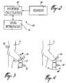
- FIG. 2is a block diagram of a 3-D kinematic representation system in accordance with the present invention.
- FIG. 3is a schematic view of a step of a calibration method of the present invention wherein a femoral head center is obtained;
- FIG. 4is a schematic view of a step of the calibration method wherein a knee axis is obtained
- FIG. 5 ais a schematic view of a step of the calibration method wherein a desired posture is registered
- FIG. 5 bis a schematic view of the step of FIG. 5 a , the calibration method by which an alternative way of registering a desired posture is shown;
- FIG. 5 cis a top plan view of a template secured to a wall in which feet of a patient are positioned;
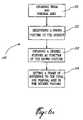
- FIG. 6 ais a block diagram illustrating the calibration method
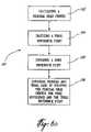
- FIG. 6 bis a block diagram illustrating a first step of the calibration method
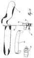
- FIG. 7is a perspective view of a harness constructed in accordance with the present invention.
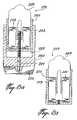
- FIGS. 8 a and 8 bare sectional views of a clamping means of the harness located on a lateral and medial sides of the knee, respectively;
- FIG. 9is a perspective view of a tibial attachment means in accordance with the present invention.
- FIGS. 10 a and 10 bare respectively medial and lateral views of the anatomical structures of the knee, permitting the identification of installation sites of the harness on the knee;
- FIG. 11is a schematic and block diagram representing the system for analysis of the three-dimensional kinematic of the knee
- FIG. 12is a perspective view of the harness as assembled for being used on a right leg
- FIG. 13is a perspective view of the harness as disassembled from FIG. 12 ;
- FIG. 14is a perspective view of the harness as assembled for being used on a left leg.
- FIG. 15is a perspective view of the harness as disassembled from FIG. 14 .
- a right leg of a personis generally shown at 10 .
- the femur 12has a femoral head 20 at an upper end thereof, and a lateral condyle 22 and a median condyle 24 at a bottom end thereof.
- the femoral head 20is received in the pelvis 18 , and the engagement therebetween is equivalent to that of a spherical joint (i.e., three rotational degrees of freedom).
- the tibia 14also has a lateral condyle 28 and a median condyle 30 upon which rest the lateral condyle 22 and the median condyle 24 of the femur 12 , respectively.
- the tibia 14further comprises a median malleolus 32 .
- the fibula 16has a lateral malleolus 36 .
- the calibration method of the present inventionwill enable placement of a frame of reference in the form of a femoral coordinate system on the femur 12 and a tibial coordinate system on the tibia 14 , in a reproducible manner from calibration to calibration, such that the frame of reference can be used as a reference during the 3-D kinematic analysis as reference.
- a femoral axis Z 1 of the femoral coordinate systemextends from a point P 1 , at a center of the femoral head 20 , to a point P 2 , at a condyle midpoint of a flexion/extension axis A 1 , as will be described in further detail hereinafter.
- a tibial axis Z 2 of the tibial coordinate systemprojects from the point P 2 to a point P 3 , which is at a midpoint between outermost points of the median malleolus 32 of the tibia 14 and the lateral malleolus 36 of the fibula 16 .
- the 3-D kinematic representation system 40typically comprises a position calculator 42 , which is a computer having a position calculator software.
- the position calculator 42is wired to sensors 44 , which detects the position and orientation in a working range thereof of detectable devices.
- User interfaces 46are also connected to the position calculator 42 and enable a user to control the position calculator 42 or view the 3-D representation outputted thereby.
- the user interfaces 46are typically a monitor, a keyboard and a mouse.
- a first step 101 of the calibration method 100is illustrated.
- a first marker 50Prior to the calibration method 100 , a first marker 50 must be immovably secured to the femur 12 .
- the first marker 50is trackable in space for position and orientation. Therefore, the first marker 50 has at least three points thereof detectable and in a known relation, such that all six degrees of freedom of the first marker 50 are calculable when tracking same.
- the first marker 50is held against a lower portion of the femur 12 , such as the condyle 28 or 30 , where only a thin layer of skin tissue separates the first marker 50 from the femur 12 .
- first marker 50With the fixed relationship between the first marker 50 and the femur 12 , the tracking of the first marker 50 ensures that a femoral reference point given by the first marker 50 is in a fixed relation with the femur 12 throughout the calibration and the 3-D kinematic analysis. Therefore, other points may be established on the femur 12 with respect to the femoral reference point so as to be trackable in space through the first marker 50 .
- Various types of first markers 50may be used, and it is preferable to use clamping devices such as the harness disclosed in International Publication No. WO 01/32080 A1, which minimizes the movement of the first marker 50 with respect to the femur, whereby this movement is negligible.
- the harness disclosed thereinis advantageous, as its construction allows for it to be used on either the right or the left leg by detaching the arch portion thereof and reconnecting it for the change of leg. Also, the harness disclosed in this publication follows the knee closely in its median portion, whereby it does not interfere with the gait of the person so as to have a good representation thereof in the kinematic analysis. This will be described in detail hereinafter.
- a second marker 52trackable for position and orientation, must be applied to the tibia 14 so as to remain fixed thereon throughout the calibration to define a tibial reference point at a point of contact between the second marker 52 and the lower leg.
- the first marker 50 and the second marker 52are to be used for the 3-D kinematic analysis of the leg, and must be calibrated.
- the markers 50 and 52are the trackable references with respect to which the frame of reference will be created.
- step 101the femoral axis Z 1 and the tibial axis Z 2 are obtained. More specifically, referring to FIG. 6 b , step 101 is divided into various steps.
- step 102the center P 1 of the femoral head 20 is positioned with respect to the femoral trackable reference (i.e., as given by the first marker 50 ). This is achieved, for instance, by a patient P (i.e., a subject of the kinematic analysis) doing a leg circling movement with his knee K generally defining circles, as shown by arrow M 1 . Other motions can be performed to obtain the femoral head center.
- the femur 12rotates as a result of the femoral head 20 being in a spherical joint relationship with the pelvis 18 .
- This motionis tracked by the sensors 44 recording the motions of the first marker 50 , thereby enabling the position calculator 42 to calculate the position of the point P 1 .
- the pelvis 18will move, which will create unwanted displacement of the first marker 50 during the step 102 . Therefore, this displacement must be taken into account in calculating the position of the point P 1 with respect to the femoral reference point given by the first marker 50 . Therefore, as illustrated in FIG.
- a third movable marker 54is positioned against the pelvis 18 (preferably on the sacrum, where the skin layer is thin) in order to record the motion of the pelvis 18 while the knee K is doing the circling motion. Therefore, the motion of the pelvis 18 and of the first marker 50 are measured, and the motion of the first marker 50 is calculated with respect to the motion of the pelvis 18 .
- the center of the femoral head P 1is calculated by the position calculator 42 . It is pointed out that other methods can be used to position the femoral head center, e.g., using regression equations.
- a step 104follows the step 102 in the calibration method 100 .
- a tibial reference pointis digitized. This is achieved, for instance, by an operator manually finding the outermost points of the lateral malleolus 36 of the fibula 16 and of the median malleolus 32 of the tibia 14 .
- a position for each of the outermost pointsis digitized with respect to the tibial reference point of the second marker 52 using, for instance, the movable third marker 54 .
- a marker having a reference point at a tip of a pointer thereofis preferably used.
- a malleolus axis A 2is then defined between these two outermost points.
- a point P 3is defined as the median point between the outermost portions of the median malleolus 32 and the lateral malleolus 36 , on the malleolus axis A 2 .
- a step 106 of the calibration method 100is shown.
- a knee reference pointis obtained with respect to the reference system. This is achieved by the lower portion of the leg making flexion/extension motions shown at M 2 .
- the lower legdoes a kicking motion.
- the knee jointacts as a special hinge which allows the tibia 14 to move with respect to the femur 12 in a three-degrees-of-freedom manner.
- the tracking for position and orientation of these markerswill enable calculation by the position calculator 42 of a mean flexion/extension axis A 1 , about which the lower leg has movements in three degrees of freedom (i.e., two rotations and one translation). Now that the mean flexion/extension axis A 1 has been determined, a midpoint P 2 thereof is calculated. To do so, the knee thickness at that point must be known.
- the operatormanually finds the outermost points of the knee, i.e., the outermost points of the lateral condyle 22 and of the median condyle 24 of the femur 12 using the movable third marker 54 .
- a thickness approximation of the femur 12 at the knee jointis known.
- a midpoint P 2is then calculated as half the thickness and positioned (transposed) at the midpoint of the flexion/extension axis A 1 .
- the points P 1 , P 2 and P 3are now all digitized and their positions are calculable as a function of the femoral trackable reference (the first marker 50 ) and the tibial reference (the second marker 52 ). Therefore, according to step 108 of FIG. 6 b , the points P 1 and P 2 are related to define the femoral axis Z 1 , and the points P 2 and P 3 are related to define the tibial axis Z 2 , whereby step 101 of the calibration method 100 is completed. These axes are positioned advantageously for representing leg movements, as the points P 1 , P 2 and P 3 each represent points about which motion occurs.
- the steps 102 , 104 and 106can be performed in any sequence.
- the femoral axis Z 1 and the tibial axis Z 2can be used as a frame of reference to gather some information relating to knee kinematics.
- a step 110follows the step 101 of the calibration method 100 .
- a known posture of the patient Pis registered with respect to the trackable references (markers 50 and 52 ).
- One way of achieving the step 110 and registering the known postureis by having the patient P positioned with his back to a wall W.
- the plane of the wall Wis digitized, and this is possible by getting three points thereof digitized with the movable third marker 54 , such that the position calculator 42 may calculate the position and orientation of the plane of the wall W, with respect to the trackable references.
- a template Tas illustrated in FIG.
- a sagittal plane of the subjectis defined by the normal of the frontal plane and the vector joining points P 1 and P 3 .
- a desired postureis obtained with respect to the trackable references as a function of the known posture. This is achieved by the patient P executing small flexion/extension movements by bending down slightly while keeping his back against the wall (the known posture). In doing so, the full extension of the knee (i.e., at a flexion of 0° between the femoral axis Z 1 and the tibial axis Z 2 ) is identified by the position calculator 42 . As mentioned above, the full extension is defined at the moment when the angle between the projections on the sagittal plane of Z 1 and Z 2 is minimal. The desired posture of the knee is then determined at that moment.
- step 114follows.
- a frame of referenceis set to the femoral and tibial axes Z 1 and Z 2 , respectively, as a function of the desired posture of the leg. More specifically, as shown in FIG. 1 , the frame of reference has the femoral coordinate system and the tibial coordinate system.
- the femoral coordinate systemoriginates from point P 2 and incorporates the femoral axis Z 1 .
- a second femoral axis Y 1is calculated as being perpendicular to the femoral axis Z 1 while lying in the sagittal plane of the subject at the desired posture.
- a third femoral axis X 1is calculated as being perpendicular to the femoral axis Z 1 and the second femoral axis Y 1 .
- the tibial coordinate systemoriginates from point P 2 and incorporates the tibial axis Z 2 .
- a second tibial axis Y 2is calculated as being perpendicular to the tibial axis Z 2 while lying in the sagittal plane of the subject at the desired posture.
- a third tibial axis X 2is calculated as being perpendicular to the tibial axis Z 2 and the second tibial axis Y 2 .
- step 110is performed by the patient initially positioned with his back to a wall W and his feet F in the template T secured to the wall W, as shown in FIG. 5 b .
- An axis TY of the template Tis digitized, perpendicular to the wall W and parallel with the ground G.
- the template Talso permits an axis TX to be digitized, which is parallel to the wall W and to the ground G.
- An axis TZis calculated by the position calculator 42 and is perpendicular to the ground G.
- the frontal plane and the sagittal planecan be registered with respect to the wall W, as the subject stands against the wall W.
- the plane of the wall Wis calculated from the TX, TY, TZ coordinate system. Therefore, this known posture of the subject is registered with respect to the trackable references (markers 50 and 52 ).
- the desired posturemust be obtained as a function of the known posture.
- the position calculator 42determining a position for the foot F of the referenced leg where it is to be placed with respect to the template T.
- One way to elevate the foot Fconsists in using an object B with adjustable height along TZ which can be placed under the foot F at determined distances along TX and TY. In this position, both points P 1 and P 3 will be in the sagittal plane registered for the known posture in step 110 .
- the position calculator 42calculates the position of the foot on the object B as a function of the flexion angle between axis Z 1 and axis Z 2 . For instance, an angle of 10° is suitable between the axes. It is noted that the angle is measured from point P 2 , with axis Z 2 projecting upwardly from point P 2 to define an angle with axis Z 1 .
- the kneeis then oscillated laterally, i.e., in a direction generally parallel to the frontal plane, while the subject remains against the wall W and the foot F in position on the object B.
- the point P 2i.e., the knee reference point
- the position calculator 42records this as the desired posture.
- femoral and tibial axes Xare defined as being simultaneously parallel to the frontal plane and perpendicular to the respective axes Z.
- the femoral axis X 1is positioned to intersect the axis Z 1 at the point P 2
- the tibial axis X 2is positioned to intersect the axis Z 2 , also at the point P 2 , and are shown by X 1 and X 2 in FIG. 1 , respectively.
- the femoral axis Y 1 and the tibial axis Y 2are positioned intersecting the axis Z 1 and the axis Z 2 at the point P 2 , respectively, thereby completing the femoral and tibial coordinate systems in an orthonormal fashion, which will serve as frame of reference for a subsequent 3-D kinematic representation in which the markers 50 and 52 will be tracked. Therefore, the calibration method provides reproducible positioning of the femoral coordinate system and the tibial coordinate system.
- This harness 200comprises a rigid and non-flexible frame 201 which is formed as a rigid arch. At each end of the frame 201 there is provided a medial rigid support 203 and a lateral rigid support 202 . The distance between the ends is fixed or adjustable.
- the harness 200further comprises two resilient clamping means, 216 and 217 as shown in FIGS. 8 a and 8 b , each of them comprising a rigid housing 204 and 205 in which there are retained two rigid abutment elements 206 and 207 , respectively, each having an outer end configured to fit the shape of a condyle.
- the rigid abutment element 206will abut against a lateral portion of the knee, whereas the rigid abutment element 207 will abut against a median portion of the knee.
- Springs 218 and 219or any other resilient means, apply an outward force on the abutment elements.
- At least one of the clamping means 216 and 217could be secured to rigid supports 202 or 203 by adjustable means, e.g., in sliding fit adjustment in a cavity 220 formed in rigid housing 204 .
- This adjustable meansis hereinshown as being an adjustment screw 221 having a finger gripping head 222 .
- the springs 218 and 219are also interchangeable to vary the force of the abutment elements 206 and 207 .
- the harness 200further comprises a non-resilient adjustable stabilizing element 223 comprising a threaded rod 213 having an abutment pad 211 at an outer end thereof.
- This stabilizing element 223is being secured to a support frame 212 , which support frame 212 , is connected to the rigid frame 203 by adjustable means herein a screw attachment 215 .
- the support frame 212may thus pivot with respect to the rigid support 203 , and then be immobilized by tightening the screw attachment 215 .
- the position of the pad 211is adjusted by an adjustment wheel 214 .
- the medial rigid support 203defines openings 250 and 251 on opposed surfaces thereof.
- the openings 250 and 251are both sized and shaped for receiving a free end of the arch 201 .
- the reception of the arch 201 in either opening 250 or 251is achieved by an interference fit, a snap-fit engagement, or the like, so as to releasably secure the arch 201 with the medial rigid support. 203 .
- the arch 201is received in the free opening 250 for the harness 200 to be used on the right leg, and in the opening 251 for the harness 200 to be used on the left leg.
- the lateral rigid support 202may, although not required for the harness 200 to be reversible, be detached from the arch 201 , as shown in FIGS. 13 and 15 .
- the harness 200further comprises an attachment means in the form of a bar 208 .
- This attachment bar 208is in the form of a long narrow flat plate and could be formed of two sections interconnected by a hinge 209 or by a pivot.
- the attachment bar 208could be secured by a VelcroTM strap 210 or by other attachment means above the knee of the wearer.
- This attachment meanscomprises a tibia attachment bar 224 secured below the knee by means of two adjustable VelcroTM straps 225 and 226 , or by other attachment means.
- This attachment bar 224is also in the form of a long narrow flat plate.
- the harness 200is installed on the knee 227 by urging the abutment elements 206 and 207 of the clamping means 216 and 217 against the skin at predetermined sites 229 and 228 , respectively, on the knee. These predetermined sites are located laterally between the ilio-tibial band 232 and the biceps femoris tendon 233 of the knee and medially between the vastus medialis 230 and the sartorius tendon 231 of the knee.
- the harness 200is thereafter secured proximally, rigidly attaching the attachment bar 208 against the medial side of the thigh and securing this attachment bar by means of the VelcroTM strap 210 .
- the harness stabilityis adjusted by means of the adjustable screw wheel 214 .
- the abutment pad 211 of the stabilizing element 223is urged against skin in alignment with the center of the medial condyle 228 . Therefore, by its configuration, the harness 200 is secured to the upper portion of the leg in a non-invasive manner.
- Various detectable devicesmay be secured to the harness 200 , such that the harness 200 is tracked for position and orientation in space. As the harness 200 is fixedly secured to the upper leg, whereas the tibial attachment 227 is fixedly secured to the lower leg, the dual tracking for position and orientation gives precise information about relative knee motion.
- the tibia attachment bar 224is installed by adjusting its position so that the bar 224 urges on the anterior side of the tibia, below the tuberosity 234 of the tibia 235 , securing the tibia attachment bar 224 below this tuberosity by means of the adjustable straps 225 and 226 .
- the harness 200is provided with localizing sensors 236 and the tibial attachment bar 224 is also provided with localizing sensors 237 to position the localizing sensors 237 on the tibia of the knee.
- the localizing sensors 236 or 237could be of any type (electromagnetic, opto-electronic, ultrasonic, retro-reflective, etc.) and could provide data on their three-dimensional positions or their three-dimensional positions and orientations, with respect to an external reference, or with respect to one another. Their positions are tracked using a camera (not shown). When using ultrasonic sensors, their positions are tracked by a ultrasound tx/rx. Their three-dimensional position and orientation can also be determined by their relationship to one another. When using electromagnetic tracking sensors their three-dimensional position and orientation is tracked with an electromagnetic field emitter/receiver.
- the harness 200 and the tibial attachment bar 224are installed on the knee to be analyzed.
- a knee postureis adopted or movement of the knee is performed. This movement could consist of walking, or walking on a treadmill, or bending and/or stretching the knee.
- the movementcould be guided by a person or by an apparatus.
- Datais generated by the localizing sensors 236 and 237 , and the data is treated and analyzed by computerized program means 238 or equivalent electronic means.
- the treatment of the datacould reside in the calculation of mathematical relationships relating the femur to the tibia in space using initially the above-described calibration methods. These relationships could be calculated with the definition on the femur and on the tibia of a coordinate system representing the location of the femur and the tibia, respectively. This latter definition could be accomplished on computerized models which are thereafter calibrated on real bones.
- the mathematical relationships, rotations, translations, helicoidal axis, etc.,are used to calculate knee movement indexes data 239 used in the description of the posture, or the movement of the knee.
- the methodcomprises attaching the harness about a knee femur in the manner as above described and securing the tibial attachment rod to the knee tibia in a fixed relationship.
- Datais generated by the localizing sensors secured to the harness and the tibial attachment rod. This data localizes the sensors in space and in time. The location of the sensors is detected at specific time intervals to provide location data at the time intervals. This data is treated, analyzed and resulting data is generated which describes the knee to which the harness and tibial attachment means is secured.
- the attachment rod which is connected to the harnessis placed against the medial side of thigh and attached by means of straps above the knee.
- the stability of the harnessis verified even after the knee has been flexed a few times.
- the position of the stabilizing element on the medial sideis adjusted so that one extremity urges against the skin in alignment with the center of the condyle when the knee is in extension.
- the position of the attachment meansis adjusted so that it urges on the interior side of the tibia below the two tuberosity of the tibia and it is attached below the two tuberosity of the tibia.
- the measurementsare taken when the knee is in movement and this is achieved by walking on a floor surface or walking on a treadmill or jumping at least one or a few times, or bending the knee at least once or stretching the knee at least one time.
- the movementis guided by a person or an apparatus.
- FIGS. 12 to 15show the various elements of the harness 200 as disassembled and mounted for being used either on the right femur ( FIG. 12 ) or the left knee ( FIG. 14 ). It is pointed out that the medial rigid support 203 is reduced in width so as to prevent it from impeding the gait of the patient. It has also been thought to use two harnesses at the same time, for either leg.
Landscapes
- Health & Medical Sciences (AREA)
- Life Sciences & Earth Sciences (AREA)
- Biomedical Technology (AREA)
- Heart & Thoracic Surgery (AREA)
- Veterinary Medicine (AREA)
- Physics & Mathematics (AREA)
- Oral & Maxillofacial Surgery (AREA)
- Biophysics (AREA)
- Pathology (AREA)
- Engineering & Computer Science (AREA)
- Dentistry (AREA)
- Public Health (AREA)
- Medical Informatics (AREA)
- Molecular Biology (AREA)
- Surgery (AREA)
- Animal Behavior & Ethology (AREA)
- General Health & Medical Sciences (AREA)
- Orthopedic Medicine & Surgery (AREA)
- Rheumatology (AREA)
- Measurement Of The Respiration, Hearing Ability, Form, And Blood Characteristics Of Living Organisms (AREA)
- Prostheses (AREA)
- Processing Or Creating Images (AREA)
Abstract
Description
Claims (3)
Priority Applications (1)
| Application Number | Priority Date | Filing Date | Title |
|---|---|---|---|
| US10/497,170US7481780B2 (en) | 2001-12-11 | 2002-12-11 | Method of calibration for the representation of knee kinematics and harness for use therewith |
Applications Claiming Priority (3)
| Application Number | Priority Date | Filing Date | Title |
|---|---|---|---|
| US33870101P | 2001-12-11 | 2001-12-11 | |
| PCT/CA2002/001916WO2003053244A2 (en) | 2001-12-11 | 2002-12-11 | Method of calibration for the representation of knee kinematics and harness for use therewith |
| US10/497,170US7481780B2 (en) | 2001-12-11 | 2002-12-11 | Method of calibration for the representation of knee kinematics and harness for use therewith |
Publications (2)
| Publication Number | Publication Date |
|---|---|
| US20050143676A1 US20050143676A1 (en) | 2005-06-30 |
| US7481780B2true US7481780B2 (en) | 2009-01-27 |
Family
ID=23325796
Family Applications (1)
| Application Number | Title | Priority Date | Filing Date |
|---|---|---|---|
| US10/497,170Expired - Fee RelatedUS7481780B2 (en) | 2001-12-11 | 2002-12-11 | Method of calibration for the representation of knee kinematics and harness for use therewith |
Country Status (5)
| Country | Link |
|---|---|
| US (1) | US7481780B2 (en) |
| EP (1) | EP1458289A2 (en) |
| AU (1) | AU2002351575A1 (en) |
| CA (1) | CA2509342A1 (en) |
| WO (1) | WO2003053244A2 (en) |
Cited By (16)
| Publication number | Priority date | Publication date | Assignee | Title |
|---|---|---|---|---|
| US20090088674A1 (en)* | 2007-09-30 | 2009-04-02 | James Caillouette | Method and system for designing patient-specific orthopaedic surgical instruments |
| US20100312149A1 (en)* | 2007-11-26 | 2010-12-09 | Nicola Hagemeister | Harness system for kinematic analysis of the knee |
| US20110054851A1 (en)* | 2007-07-06 | 2011-03-03 | Markus Heller | Method for detecting information relevant for the characterization of joint movements |
| US20120116252A1 (en)* | 2010-10-13 | 2012-05-10 | The Regents Of The University Of Colorado, A Body Corporate | Systems and methods for detecting body orientation or posture |
| US8265949B2 (en) | 2007-09-27 | 2012-09-11 | Depuy Products, Inc. | Customized patient surgical plan |
| US8361076B2 (en) | 2007-09-30 | 2013-01-29 | Depuy Products, Inc. | Patient-customizable device and system for performing an orthopaedic surgical procedure |
| US20140276885A1 (en)* | 2013-03-18 | 2014-09-18 | Orthosensor Inc | System and method for measuring muscular-skeletal alignment to a mechanical axis |
| US20150105780A1 (en)* | 2012-03-01 | 2015-04-16 | Ostesys | Method and system for determining the alignment of two bones |
| US9532732B2 (en) | 2010-05-03 | 2017-01-03 | Emovi Inc. | Method and system for knee joint evaluation and diagnostic aid in normal and pathologic state |
| US10638970B2 (en) | 2017-03-08 | 2020-05-05 | Strive Orthopedics, Inc | Method for identifying human joint characteristics |
| US10842432B2 (en) | 2017-09-14 | 2020-11-24 | Orthosensor Inc. | Medial-lateral insert sensing system with common module and method therefor |
| US20210007864A1 (en)* | 2016-03-03 | 2021-01-14 | Orthosensor Inc | Orthopedic leg alignment system and method |
| US10993639B2 (en) | 2014-04-25 | 2021-05-04 | Massachusetts Institute Of Technology | Feedback method and wearable device to monitor and modulate knee adduction moment |
| US11051829B2 (en) | 2018-06-26 | 2021-07-06 | DePuy Synthes Products, Inc. | Customized patient-specific orthopaedic surgical instrument |
| US11793424B2 (en) | 2013-03-18 | 2023-10-24 | Orthosensor, Inc. | Kinetic assessment and alignment of the muscular-skeletal system and method therefor |
| US11812978B2 (en) | 2019-10-15 | 2023-11-14 | Orthosensor Inc. | Knee balancing system using patient specific instruments |
Families Citing this family (20)
| Publication number | Priority date | Publication date | Assignee | Title |
|---|---|---|---|---|
| DE10313747A1 (en)* | 2003-03-27 | 2004-10-28 | Aesculap Ag & Co. Kg | Joint hinging and articulation investigation system is used for examination of problems with knee joints and uses pins with markers fixed to tibia and femur with positions sensed by navigation system |
| CA2658510C (en)* | 2006-07-21 | 2013-01-15 | Orthosoft Inc. | Non-invasive tracking of bones for surgery |
| US20080091373A1 (en)* | 2006-07-31 | 2008-04-17 | University Of New Brunswick | Method for calibrating sensor positions in a human movement measurement and analysis system |
| EP2164419A1 (en)* | 2007-11-08 | 2010-03-24 | Orthosoft, Inc. | Trackable reference device for computer-assisted surgery |
| WO2009111888A1 (en)* | 2008-03-13 | 2009-09-17 | Orthosoft Inc. | Tracking cas system |
| GB0806813D0 (en)* | 2008-04-15 | 2008-05-14 | Smith & Nephew Orthopaedics Ag | Medical navigation method and system |
| WO2010082156A1 (en)* | 2009-01-16 | 2010-07-22 | Koninklijke Philips Electronics N.V. | Method for automatic alignment of a position and orientation indicator and device for monitoring the movements of a body part |
| DE102010008985A1 (en)* | 2010-02-24 | 2011-06-30 | Deutsches Zentrum für Luft- und Raumfahrt e.V., 51147 | Tracing device i.e. marker, for movement-tracing of finger limb in human hand, has reflection elements arranged at distance to each other to determine position and orientation of human limb to be traced in simultaneous manner |
| JP5755734B2 (en) | 2010-06-16 | 2015-07-29 | エーツー・サージカル | Method and system for automatically determining geometric elements from 3D medical images of bone |
| US9020223B2 (en) | 2010-06-16 | 2015-04-28 | A2 Surgical | Method for determining bone resection on a deformed bone surface from few parameters |
| WO2011158116A2 (en) | 2010-06-16 | 2011-12-22 | A2 Surgical | A method for determining articular bone deformity resection using motion patterns |
| EP2583246B1 (en) | 2010-06-16 | 2019-01-30 | A² Surgical | Method and system of automatic determination of geometric elements characterizing a bone deformation from 3d image |
| JP6040151B2 (en) | 2010-06-16 | 2016-12-07 | エーツー・サージカル | Method for determining access region from 3D patient image |
| US9597156B2 (en)* | 2010-07-30 | 2017-03-21 | Orthosoft Inc. | Bone tracking with a gyroscope sensor in computer-assisted surgery |
| US8551108B2 (en) | 2010-08-31 | 2013-10-08 | Orthosoft Inc. | Tool and method for digital acquisition of a tibial mechanical axis |
| EP2611379B1 (en)* | 2010-08-31 | 2017-12-27 | Orthosoft Inc. | Tool for digital acquisition of a tibial mechanical axis |
| US8696675B2 (en)* | 2010-08-31 | 2014-04-15 | Orthosoft Inc. | Proximity-triggered computer-assisted surgery system and method |
| US11446090B2 (en) | 2017-04-07 | 2022-09-20 | Orthosoft Ulc | Non-invasive system and method for tracking bones |
| CA3053904A1 (en) | 2018-08-31 | 2020-02-29 | Orthosoft Inc. | System and method for tracking bones |
| CN110934597B (en)* | 2019-12-30 | 2023-07-18 | 龙岩学院 | A method of operating an abnormal gait monitoring device |
Citations (14)
| Publication number | Priority date | Publication date | Assignee | Title |
|---|---|---|---|---|
| US4425713A (en)* | 1982-08-25 | 1984-01-17 | Rotella Sam S | Postureometer |
| US4631676A (en)* | 1983-05-25 | 1986-12-23 | Hospital For Joint Diseases Or | Computerized video gait and motion analysis system and method |
| US4649934A (en)* | 1985-06-07 | 1987-03-17 | Faro Medical Technologies, Inc. | Joint laxity measurement |
| US4730625A (en)* | 1986-12-15 | 1988-03-15 | Faro Medical Technologies Inc. | Posture monitoring system |
| US4804000A (en)* | 1987-01-21 | 1989-02-14 | Steve Lamb | Dynamic sagittal knee test apparatus |
| US5007912A (en)* | 1990-05-30 | 1991-04-16 | Albrektsson Bjoern | Arrangement for fixing a knee-joint in defined positions and for positional control of instruments for replacing the knee-joint with a prosthesis |
| US5611353A (en)* | 1993-06-21 | 1997-03-18 | Osteonics Corp. | Method and apparatus for locating functional structures of the lower leg during knee surgery |
| US5682886A (en)* | 1995-12-26 | 1997-11-04 | Musculographics Inc | Computer-assisted surgical system |
| WO2000048507A1 (en) | 1999-02-16 | 2000-08-24 | Frederic Picard | Optimizing alignment of an appendicular |
| WO2001032080A1 (en) | 1999-11-01 | 2001-05-10 | Ecole De Technologie Superieure | A system for the analysis of 3d kinematic of the knee |
| US6692447B1 (en)* | 1999-02-16 | 2004-02-17 | Frederic Picard | Optimizing alignment of an appendicular |
| US20040230199A1 (en)* | 2002-10-04 | 2004-11-18 | Jansen Herbert Andre | Computer-assisted hip replacement surgery |
| US6890312B1 (en)* | 2001-12-03 | 2005-05-10 | William B. Priester | Joint angle indication system |
| US20060282023A1 (en) | 2002-12-03 | 2006-12-14 | Aesculap Ag & Co. Kg | Method of determining the position of the articular point of a joint |
- 2002
- 2002-12-11WOPCT/CA2002/001916patent/WO2003053244A2/ennot_activeApplication Discontinuation
- 2002-12-11USUS10/497,170patent/US7481780B2/ennot_activeExpired - Fee Related
- 2002-12-11EPEP02787249Apatent/EP1458289A2/ennot_activeWithdrawn
- 2002-12-11CACA002509342Apatent/CA2509342A1/ennot_activeAbandoned
- 2002-12-11AUAU2002351575Apatent/AU2002351575A1/ennot_activeAbandoned
Patent Citations (15)
| Publication number | Priority date | Publication date | Assignee | Title |
|---|---|---|---|---|
| US4425713A (en)* | 1982-08-25 | 1984-01-17 | Rotella Sam S | Postureometer |
| US4631676A (en)* | 1983-05-25 | 1986-12-23 | Hospital For Joint Diseases Or | Computerized video gait and motion analysis system and method |
| US4649934A (en)* | 1985-06-07 | 1987-03-17 | Faro Medical Technologies, Inc. | Joint laxity measurement |
| US4730625A (en)* | 1986-12-15 | 1988-03-15 | Faro Medical Technologies Inc. | Posture monitoring system |
| US4804000A (en)* | 1987-01-21 | 1989-02-14 | Steve Lamb | Dynamic sagittal knee test apparatus |
| US5007912A (en)* | 1990-05-30 | 1991-04-16 | Albrektsson Bjoern | Arrangement for fixing a knee-joint in defined positions and for positional control of instruments for replacing the knee-joint with a prosthesis |
| US5611353A (en)* | 1993-06-21 | 1997-03-18 | Osteonics Corp. | Method and apparatus for locating functional structures of the lower leg during knee surgery |
| US5682886A (en)* | 1995-12-26 | 1997-11-04 | Musculographics Inc | Computer-assisted surgical system |
| WO2000048507A1 (en) | 1999-02-16 | 2000-08-24 | Frederic Picard | Optimizing alignment of an appendicular |
| US6692447B1 (en)* | 1999-02-16 | 2004-02-17 | Frederic Picard | Optimizing alignment of an appendicular |
| WO2001032080A1 (en) | 1999-11-01 | 2001-05-10 | Ecole De Technologie Superieure | A system for the analysis of 3d kinematic of the knee |
| US6890312B1 (en)* | 2001-12-03 | 2005-05-10 | William B. Priester | Joint angle indication system |
| US20040230199A1 (en)* | 2002-10-04 | 2004-11-18 | Jansen Herbert Andre | Computer-assisted hip replacement surgery |
| US20060282023A1 (en) | 2002-12-03 | 2006-12-14 | Aesculap Ag & Co. Kg | Method of determining the position of the articular point of a joint |
| US7209776B2 (en) | 2002-12-03 | 2007-04-24 | Aesculap Ag & Co. Kg | Method of determining the position of the articular point of a joint |
Non-Patent Citations (1)
| Title |
|---|
| Alexander L. Bell et al., A Comparison of the Accuracy of Several Hip Center Location Prediction Methods, Journal of Biomechanics, vol. 23, No. 6, pp. 617-621. |
Cited By (32)
| Publication number | Priority date | Publication date | Assignee | Title |
|---|---|---|---|---|
| US20110054851A1 (en)* | 2007-07-06 | 2011-03-03 | Markus Heller | Method for detecting information relevant for the characterization of joint movements |
| US8265949B2 (en) | 2007-09-27 | 2012-09-11 | Depuy Products, Inc. | Customized patient surgical plan |
| US12070231B2 (en) | 2007-09-27 | 2024-08-27 | DePuy Synthes Products, Inc. | Customized patient surgical plan |
| US11931049B2 (en) | 2007-09-30 | 2024-03-19 | DePuy Synthes Products, Inc. | Apparatus and method for fabricating a customized patient-specific orthopaedic instrument |
| US8357111B2 (en)* | 2007-09-30 | 2013-01-22 | Depuy Products, Inc. | Method and system for designing patient-specific orthopaedic surgical instruments |
| US8361076B2 (en) | 2007-09-30 | 2013-01-29 | Depuy Products, Inc. | Patient-customizable device and system for performing an orthopaedic surgical procedure |
| US11696768B2 (en) | 2007-09-30 | 2023-07-11 | DePuy Synthes Products, Inc. | Apparatus and method for fabricating a customized patient-specific orthopaedic instrument |
| US20090088674A1 (en)* | 2007-09-30 | 2009-04-02 | James Caillouette | Method and system for designing patient-specific orthopaedic surgical instruments |
| US10028750B2 (en) | 2007-09-30 | 2018-07-24 | DePuy Synthes Products, Inc. | Apparatus and method for fabricating a customized patient-specific orthopaedic instrument |
| US10828046B2 (en) | 2007-09-30 | 2020-11-10 | DePuy Synthes Products, Inc. | Apparatus and method for fabricating a customized patient-specific orthopaedic instrument |
| US20100312149A1 (en)* | 2007-11-26 | 2010-12-09 | Nicola Hagemeister | Harness system for kinematic analysis of the knee |
| US9532732B2 (en) | 2010-05-03 | 2017-01-03 | Emovi Inc. | Method and system for knee joint evaluation and diagnostic aid in normal and pathologic state |
| US20120116252A1 (en)* | 2010-10-13 | 2012-05-10 | The Regents Of The University Of Colorado, A Body Corporate | Systems and methods for detecting body orientation or posture |
| US20150105780A1 (en)* | 2012-03-01 | 2015-04-16 | Ostesys | Method and system for determining the alignment of two bones |
| US10335055B2 (en) | 2013-03-18 | 2019-07-02 | Orthosensor Inc. | Kinetic assessment and alignment of the muscular-skeletal system and method therefor |
| US11109777B2 (en) | 2013-03-18 | 2021-09-07 | Orthosensor, Inc. | Kinetic assessment and alignment of the muscular-skeletal system and method therefor |
| US9492238B2 (en)* | 2013-03-18 | 2016-11-15 | Orthosensor Inc | System and method for measuring muscular-skeletal alignment to a mechanical axis |
| US11793424B2 (en) | 2013-03-18 | 2023-10-24 | Orthosensor, Inc. | Kinetic assessment and alignment of the muscular-skeletal system and method therefor |
| US20140276885A1 (en)* | 2013-03-18 | 2014-09-18 | Orthosensor Inc | System and method for measuring muscular-skeletal alignment to a mechanical axis |
| US10993639B2 (en) | 2014-04-25 | 2021-05-04 | Massachusetts Institute Of Technology | Feedback method and wearable device to monitor and modulate knee adduction moment |
| US20210007864A1 (en)* | 2016-03-03 | 2021-01-14 | Orthosensor Inc | Orthopedic leg alignment system and method |
| US11679007B2 (en)* | 2016-03-03 | 2023-06-20 | Orthosensor Inc. | Orthopedic leg alignment system and method |
| US12097130B2 (en) | 2016-03-03 | 2024-09-24 | Howmedica Osteonics, Corp. | Orthopedic leg alignment system and method |
| US11172874B2 (en) | 2017-03-08 | 2021-11-16 | Strive Orthopedics, Inc. | Sensors and a method for evaluation of characteristics of human joints and for diagnosis of joint ailments |
| US11259743B2 (en) | 2017-03-08 | 2022-03-01 | Strive Orthopedics, Inc. | Method for identifying human joint characteristics |
| US10638970B2 (en) | 2017-03-08 | 2020-05-05 | Strive Orthopedics, Inc | Method for identifying human joint characteristics |
| US11534316B2 (en) | 2017-09-14 | 2022-12-27 | Orthosensor Inc. | Insert sensing system with medial-lateral shims and method therefor |
| US10893955B2 (en) | 2017-09-14 | 2021-01-19 | Orthosensor Inc. | Non-symmetrical insert sensing system and method therefor |
| US10842432B2 (en) | 2017-09-14 | 2020-11-24 | Orthosensor Inc. | Medial-lateral insert sensing system with common module and method therefor |
| US11051829B2 (en) | 2018-06-26 | 2021-07-06 | DePuy Synthes Products, Inc. | Customized patient-specific orthopaedic surgical instrument |
| US11950786B2 (en) | 2018-06-26 | 2024-04-09 | DePuy Synthes Products, Inc. | Customized patient-specific orthopaedic surgical instrument |
| US11812978B2 (en) | 2019-10-15 | 2023-11-14 | Orthosensor Inc. | Knee balancing system using patient specific instruments |
Also Published As
| Publication number | Publication date |
|---|---|
| WO2003053244A3 (en) | 2003-08-21 |
| WO2003053244A2 (en) | 2003-07-03 |
| CA2509342A1 (en) | 2003-07-03 |
| EP1458289A2 (en) | 2004-09-22 |
| AU2002351575A1 (en) | 2003-07-09 |
| WO2003053244B1 (en) | 2003-10-16 |
| US20050143676A1 (en) | 2005-06-30 |
Similar Documents
| Publication | Publication Date | Title |
|---|---|---|
| US7481780B2 (en) | Method of calibration for the representation of knee kinematics and harness for use therewith | |
| US7291119B1 (en) | System for the analysis of 3D kinematic of the knee | |
| Fuller et al. | A comparison of lower-extremity skeletal kinematics measured using skin-and pin-mounted markers | |
| Cappozzo et al. | Position and orientation in space of bones during movement: experimental artefacts | |
| Kadaba et al. | Measurement of lower extremity kinematics during level walking | |
| Kiss et al. | Joint kinematics and spatial–temporal parameters of gait measured by an ultrasound-based system | |
| Cloete et al. | Benchmarking of a full-body inertial motion capture system for clinical gait analysis | |
| Aminian et al. | Capturing human motion using body‐fixed sensors: outdoor measurement and clinical applications | |
| EP2391971B1 (en) | Noninvasive diagnostic system | |
| Giacomozzi et al. | Integrated pressure-force-kinematics measuring system for the characterisation of plantar foot loading during locomotion | |
| WO2005018453A1 (en) | A wearable mechatronic device for the analysis of joint biomechanics | |
| US10821047B2 (en) | Method for automatic alignment of a position and orientation indicator and device for monitoring the movements of a body part | |
| US20060245627A1 (en) | Noninvasive dynamic analysis system and method of use thereof | |
| Agostini et al. | Wearable sensors for gait analysis | |
| Gastaldi et al. | Evaluation of functional methods for human movement modelling | |
| US6551258B1 (en) | Methods and apparatus for joint laxity measurements | |
| Drapeaux et al. | A comparison of inertial motion capture systems: DorsaVi and Xsens | |
| Hebert et al. | A method of measuring three-dimensional scapular attitudes using the optotrak probing system | |
| CA2427186C (en) | A system for the analysis of 3d kinematic of the knee | |
| US20180160977A1 (en) | Portable joint testing device | |
| US20110054851A1 (en) | Method for detecting information relevant for the characterization of joint movements | |
| Scattolini et al. | Inertial Sensing for Human Motion Analysis: Enabling Sensor-to-Body Calibration Through an Anatomical and Functional Combined Approach | |
| LaScalza et al. | A method for measuring Euler rotation angles and helical axis of upper arm motion | |
| Rácz et al. | Evaluation of anatomical landmark calibration accuracy of a motion capture based analysis protocol | |
| US20100312149A1 (en) | Harness system for kinematic analysis of the knee |
Legal Events
| Date | Code | Title | Description |
|---|---|---|---|
| AS | Assignment | Owner name:CORPORATION DE L'ECOLE POLYTECHNIQUE DE MONTREAL, Free format text:ASSIGNMENT OF ASSIGNORS INTEREST;ASSIGNOR:EL MAACH, ISMAIL;REEL/FRAME:017033/0140 Effective date:20031015 Owner name:CORPORATION DE L'ECOLE POLYTECHNIQUE DE MONTREAL, Free format text:ASSIGNMENT OF ASSIGNORS INTEREST;ASSIGNOR:YAHIA, L'HOCINE;REEL/FRAME:017033/0150 Effective date:20030117 Owner name:POLYVALOR, SOCIETE EN COMMANDITE, CANADA Free format text:ASSIGNMENT OF ASSIGNORS INTEREST;ASSIGNOR:CORPORATION DE L'ECOLE POLYTECHNIQUE DE MONTREAL;REEL/FRAME:017033/0154 Effective date:20040119 Owner name:CENTRE HOSPITALIER DE L'UNIVERSITE DE MONTREAL (CH Free format text:ASSIGNMENT OF ASSIGNORS INTEREST;ASSIGNOR:DUVAL, NICOLAS;REEL/FRAME:017033/0188 Effective date:20021219 Owner name:SOCOVAR SOCIETE EN COMMANDITE, CANADA Free format text:ASSIGNMENT OF ASSIGNORS INTEREST;ASSIGNOR:ECOLE DE TECHNOLOGIE SUPERIEURE;REEL/FRAME:017033/0157 Effective date:20031118 Owner name:ECOLE DE TECHNOLOGIES SU PERIEURE, CANADA Free format text:ASSIGNMENT OF ASSIGNORS INTEREST;ASSIGNORS:DE GUISE, JACQUES A.;HAGEMEISTER, NICOLA;PARENT, GERALD;AND OTHERS;REEL/FRAME:017033/0215;SIGNING DATES FROM 20030108 TO 20030121 | |
| AS | Assignment | Owner name:ECOLE DE TECHNOLOGIE SUPERIEURE, CANADA Free format text:ASSIGNMENT OF ASSIGNORS INTEREST;ASSIGNOR:SOCOVAR SOCIETE EN COMMANDITE;REEL/FRAME:022011/0842 Effective date:20081210 | |
| REMI | Maintenance fee reminder mailed | ||
| LAPS | Lapse for failure to pay maintenance fees | ||
| STCH | Information on status: patent discontinuation | Free format text:PATENT EXPIRED DUE TO NONPAYMENT OF MAINTENANCE FEES UNDER 37 CFR 1.362 | |
| FP | Expired due to failure to pay maintenance fee | Effective date:20130127 |