US7481031B2 - Load transfer plate for in situ concrete slabs - Google Patents
Load transfer plate for in situ concrete slabsDownload PDFInfo
- Publication number
- US7481031B2 US7481031B2US10/489,380US48938004AUS7481031B2US 7481031 B2US7481031 B2US 7481031B2US 48938004 AUS48938004 AUS 48938004AUS 7481031 B2US7481031 B2US 7481031B2
- Authority
- US
- United States
- Prior art keywords
- joint
- load
- slabs
- slab
- tapered
- Prior art date
- Legal status (The legal status is an assumption and is not a legal conclusion. Google has not performed a legal analysis and makes no representation as to the accuracy of the status listed.)
- Expired - Lifetime, expires
Links
Images


Classifications
- E—FIXED CONSTRUCTIONS
- E01—CONSTRUCTION OF ROADS, RAILWAYS, OR BRIDGES
- E01C—CONSTRUCTION OF, OR SURFACES FOR, ROADS, SPORTS GROUNDS, OR THE LIKE; MACHINES OR AUXILIARY TOOLS FOR CONSTRUCTION OR REPAIR
- E01C11/00—Details of pavings
- E01C11/02—Arrangement or construction of joints; Methods of making joints; Packing for joints
- E01C11/04—Arrangement or construction of joints; Methods of making joints; Packing for joints for cement concrete paving
- E01C11/14—Dowel assembly ; Design or construction of reinforcements in the area of joints
Definitions
- This inventionrelates generally to transferring loads between adjacent cast-in-place slabs and more particularly to a system for transferring, across a joint between a first slab and a second slab, a load applied to either slab.
- an undesirable side effect of having the floor slab 100 made up of numerous small sectionsis that when the floor is loaded, such as with the wheels of a moving fork lift 300 , each section of the floor may be deflected 302 relative to its neighbor causing damage 304 to the joint edge, as depicted in FIG. 3 .
- a conventional technique for reducing this type of deflection 302is to span the joint 400 with steel bars 402 each having a round cross-section. These bars 402 are commonly referred to as dowel bars.
- dowels of this typeare typically assembled into a wirework frame 500 that holds the dowels at a desired depth 502 and orientation.
- This assemblyis generally known as a dowel basket.
- dowel bars 402are misaligned 600 such that they are not oriented totally perpendicular to the joint, the dowel bars 402 can lock the joint 400 thereby undesirably restraining the joint from opening, which in turn may cause random cracks 102 .
- movement 800which is a combination of the two types of movement discussed above in connection with FIGS. 6 and 7 , can cause a situation known as corner cracking 802 .
- a piece of compressible material 1000such as foam, fiberboard, timber, or the like, is placed in an expansion joint 1002 between concrete slabs 100 - 1 and 100 - 2 .
- a round-cross-section dowel bar 402 and an end cap 1004may be used for transferring a load across the expansion joint 1002 .
- the joint 1002closes, and the dowel bar 402 goes farther into the end cap 1004 .
- Applicants' U.S. Pat. No. 6,354,760discloses a load plate that overcomes the drawbacks discussed above, namely misalignment and allowing relative movement of slabs parallel to the joint.
- the '760 patentdiscloses using a load plate 1100 rotated such that the load plate has a widest portion (i.e., opposite corners) of the load plate positioned in the joint between slabs 100 - 1 and 100 - 2 .
- Using such a load plate 1100 at a construction jointworks well because the load plate can be reliably centered at the construction joint between the slabs 100 .
- a load plate 1100is not, however, ideally suited for use at saw-cut control joints. As described above, this type of joint results from cracking induced by a saw cut in the upper surface of a concrete slab. The saw cut may be off center with respect to any load plate embedded within the cement, as shown by the dashed line 1200 in FIG. 12 . If the saw cut and joint are off-center, the load plate will not function as intended because more than half of the load plate will be fixed within one of the slabs and less than half of the load plate will be available for transferring loads to and from the other slab. Another situation for which a load plate 1100 is not ideally suited is when a construction joint, formed by an edge form, for instance, is expected to be relatively wide open.
- load plates 1100may undesirably be removed from slabs on either or both sides of the joint thereby reducing the ability of the load plate 1100 to transfer loads between the slabs.
- a load transfer devicethat provides the advantages of the load plate of the '760 patent and that is well suited to use in saw-cut control joints and construction joints, which may become relatively wide open, would be desirable.
- a tapered load platemay be used to transfer loads across a joint between adjacent concrete floor slabs.
- the top and bottom surfacesmay taper from approximately 4 inches wide to a narrow substantially pointed end 1308 over a length of approximately 12 inches.
- other suitable tapered shapes and/or other suitable dimensionsmay also be used.
- a tapered load platein accordance with an illustrative embodiment of the invention, advantageously accommodates misalignment of a saw cut for creating a control joint. Misalignment up to an angle substantially equal to the angle of the load plate's taper may be accommodated.
- the tapered shape of the tapered load plateadvantageously accommodates differential shrinkage of cast-in-place concrete slabs.
- the narrow end of the tapered load platemoves out of the void that it created in the slab.
- the tapered load plateretracts, it will occupy less space within the void in the slab thus allowing the slabs to move relative to one another in a direction parallel to the joint.
- Tapered load platesmay be assembled into a load-plate basket with the direction of the taper alternating from one tapered load plate to the next. If a saw cut, used for creating a control joint, is positioned off-center relative to the tapered load plates, the alternating pattern of tapered load plates in the load-plate basket will ensure that the cross section of tapered load plate material, such as steel, spanning the joint remains substantially constant across any number of pairs of tapered load plates. For use in connection with a construction joint, an edge form may be used to position tapered load plates before the slabs are cast in place.
- a tapered load plate and an end capmay be used to provide load transfer across an expansion joint.
- the tapered shape of the load platewill allow for misalignment. As either or both slabs expand and thereby cause the joint to close, the wide end of the tapered load plate moves farther into the end cap. This results in the allowance of an increasing amount of lateral movement between the slabs parallel to the joint 400 to the central and relatively wider portions of the tapered load plate occupying less space in the tapered void.
- a tapered-load-plate basketmay be used to position the tapered load plates and compressible material before the concrete slabs are cast in place.
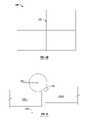
- FIG. 1is a plan view of a concrete floor slab with random cracks caused by concrete shrinkage.
- FIGS. 2A and 2Bare cross-section and plan views of saw-cut control joints.
- FIG. 3depicts vertical deflection of a floor slab under a load and damage to an adjacent floor slab.
- FIGS. 4A and 4Bare cross section and plan view of dowel bars positioned for transferring loads across joints between adjacent slabs.
- FIGS. 5A-5Care plan and sectional views of a dowel basket for positioning dowel bars before a floor slab is cast in place.
- FIG. 6is a plan view of misaligned dowel bars locking a joint and thereby causing a slab to crack.
- FIG. 7is a plan view of cracks caused by dowel bars restricting relative movement of slabs parallel to the joint between the slabs.
- FIG. 8is a plan view showing corner cracking due to misaligned dowel bars and restricted relative movement of slabs parallel to the joints.
- FIGS. 9A and 9Bare isometric and sectional views of a square dowel and square-dowel clip.
- FIG. 10is a side view of a typical expansion joint with compressible material in the joint.
- FIG. 11is a plan view of a diamond-shaped load plate between two slabs.
- FIG. 12is a plan view illustrating an off-center saw cut relative to diamond-shaped load plates.
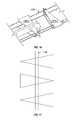
- FIG. 13shows a top and two side views of a tapered load plate in accordance with an illustrative embodiment of the invention.
- FIG. 14is a plan view showing a misaligned saw cut relative to a tapered load plate.
- FIG. 15is a plan view of a tapered load plate, two slabs, a joint, and a void created by the narrow end of the tapered load plate.
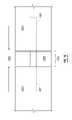
- FIG. 16shows tapered load plates in a tapered-load-plate basket, wherein the orientation of the tapered load plates alternates from one tapered load plate to the next.
- FIG. 17is a plan view showing an off-center saw cut relative to three alternately oriented tapered load plates.
- FIG. 18is a plan view of an open expansion joint, a tapered load plate, and an end cap.
- FIG. 19is a plan view similar to FIG. 18 with the joint having closed relative to FIG. 18 .
- FIG. 20is a side view of an expansion-type tapered-load-plate basket, compressible material, a tapered load plate, and an end cap.
- a tapered load platesuch as tapered load plate 1300
- the tapered load plate 1300may be used to transfer loads across a joint between adjacent concrete floor slabs.
- the tapered load plate 1300may have top and bottom surfaces that are tapered, substantially planar, and substantially parallel to one another.
- a triangular-shaped tapered top surface 1302 and two generally rectangular-shaped side surfaces 1304 and 1306are shown in FIG. 13 .
- the top and bottom surfacesmay taper from approximately 4 inches wide to a narrow substantially pointed end 1308 over a length of approximately 12 inches.
- other suitable tapered shapes and/or other suitable dimensionsmay also be used.
- a tapered load plate 1300in accordance with an illustrative embodiment of the invention, advantageously accommodates misalignment of a saw cut for creating a control joint. Misalignment up to an angle substantially equal to the angle of the load plate's taper may be accommodated.
- a misaligned saw cut 1400is misaligned by an angle 1402 from correctly aligned saw cut 1404 , which is oriented perpendicular to the tapered load plate's longitudinal axis 1406 .
- the load plate's angle of taperis depicted in FIG. 14 by angle 1408 .
- differential shrinkage of cast-in-place concrete slabsis advantageously accommodated by the tapered shape of the tapered load plate 1300 .
- adjacent slabssuch as slabs 100 - 1 and 100 - 2
- the joint 400is said to open.
- the narrow end of the tapered load plate 1300moves out of the void 1502 that it created in the slab 100 - 2 .
- the tapered load plate 1300retracts in this manner, it will occupy less space within the void in the slab 100 - 2 thus allowing the slabs 100 - 1 and 100 - 2 to move relative to one another in a direction parallel to the joint 400 .
- the narrow end of the tapered load plateoccupies less of the width of the tapered void 1502 .
- tapered load plates 1300may be assembled into a load-plate basket 1600 with the direction of the taper alternating from one tapered load plate 1300 to the next.
- FIG. 17if a saw cut 1700 , used for creating a control joint, is positioned off-center relative to the tapered load plates 1300 , the alternating pattern of tapered load plates 1300 in the load-plate basket 1600 will ensure that the cross section of tapered load plate material, such as steel, spanning the joint remains substantially constant across any number of pairs of tapered load plates 1300 .
- an edge formmay be used to position tapered load plates before the slabs are cast in place.
- a tapered load plate 1300 and an end cap 1800may be used to provide load transfer across an expansion joint of the type discussed above in connection with FIG. 10 .
- the tapered shape of the load plate 1300will allow for misalignment, as discussed above in connection with FIG. 14 .
- the wide end of the tapered load plate 1300moves farther into the end cap 1800 . This results in the allowance of an increasing amount of lateral movement between the slabs 100 - 1 and 100 - 2 parallel to the joint 400 due to the central and relatively wider portions of the tapered load plate occupying less space in the tapered void 1900 .
- a tapered-load-plate basket 2000may be used to position the tapered load plates 1300 and compressible material 1000 before the concrete slabs 100 are cast in place.
Landscapes
- Architecture (AREA)
- Civil Engineering (AREA)
- Structural Engineering (AREA)
- Engineering & Computer Science (AREA)
- Road Paving Structures (AREA)
- Joining Of Building Structures In Genera (AREA)
- Bridges Or Land Bridges (AREA)
- Building Environments (AREA)
- Curing Cements, Concrete, And Artificial Stone (AREA)
- Devices For Post-Treatments, Processing, Supply, Discharge, And Other Processes (AREA)
- Aftertreatments Of Artificial And Natural Stones (AREA)
- On-Site Construction Work That Accompanies The Preparation And Application Of Concrete (AREA)
- Air Transport Of Granular Materials (AREA)
- Conveying And Assembling Of Building Elements In Situ (AREA)
Abstract
Description
Claims (19)
Priority Applications (3)
| Application Number | Priority Date | Filing Date | Title |
|---|---|---|---|
| US10/489,380US7481031B2 (en) | 2001-09-13 | 2002-09-13 | Load transfer plate for in situ concrete slabs |
| US12/135,780US7716890B2 (en) | 2001-09-13 | 2008-06-09 | Tapered load plate for transferring loads between cast-in-place slabs |
| US12/749,148US8381470B2 (en) | 2001-09-13 | 2010-03-29 | Tapered load plate for transferring loads between cast-in-place slabs |
Applications Claiming Priority (3)
| Application Number | Priority Date | Filing Date | Title |
|---|---|---|---|
| US31883801P | 2001-09-13 | 2001-09-13 | |
| US10/489,380US7481031B2 (en) | 2001-09-13 | 2002-09-13 | Load transfer plate for in situ concrete slabs |
| PCT/US2002/029200WO2003023146A1 (en) | 2001-09-13 | 2002-09-13 | Load transfer plate for in situ concrete slabs |
Related Child Applications (1)
| Application Number | Title | Priority Date | Filing Date |
|---|---|---|---|
| US12/135,780ContinuationUS7716890B2 (en) | 2001-09-13 | 2008-06-09 | Tapered load plate for transferring loads between cast-in-place slabs |
Publications (2)
| Publication Number | Publication Date |
|---|---|
| US20040187431A1 US20040187431A1 (en) | 2004-09-30 |
| US7481031B2true US7481031B2 (en) | 2009-01-27 |
Family
ID=23239777
Family Applications (2)
| Application Number | Title | Priority Date | Filing Date |
|---|---|---|---|
| US10/489,380Expired - LifetimeUS7481031B2 (en) | 2001-09-13 | 2002-09-13 | Load transfer plate for in situ concrete slabs |
| US12/135,780Expired - LifetimeUS7716890B2 (en) | 2001-09-13 | 2008-06-09 | Tapered load plate for transferring loads between cast-in-place slabs |
Family Applications After (1)
| Application Number | Title | Priority Date | Filing Date |
|---|---|---|---|
| US12/135,780Expired - LifetimeUS7716890B2 (en) | 2001-09-13 | 2008-06-09 | Tapered load plate for transferring loads between cast-in-place slabs |
Country Status (11)
| Country | Link |
|---|---|
| US (2) | US7481031B2 (en) |
| EP (1) | EP1427888B1 (en) |
| CN (1) | CN1327083C (en) |
| AT (1) | ATE470757T1 (en) |
| AU (1) | AU2002326898B2 (en) |
| CA (1) | CA2460514C (en) |
| DE (1) | DE60236671D1 (en) |
| ES (1) | ES2347223T3 (en) |
| MX (1) | MXPA04002444A (en) |
| NZ (1) | NZ531726A (en) |
| WO (1) | WO2003023146A1 (en) |
Cited By (38)
| Publication number | Priority date | Publication date | Assignee | Title |
|---|---|---|---|---|
| US20110094041A1 (en)* | 2006-08-29 | 2011-04-28 | Rawls-Meehan Martin B | Foam spring mattress using a foam containment facility |
| US20110258958A1 (en)* | 2010-04-21 | 2011-10-27 | Russell Boxall | Transferring loads across joints in concrete slabs |
| US8465222B1 (en) | 2012-03-19 | 2013-06-18 | Ziad Ghauch | Load transfer apparatus for cast-in-place concrete slabs |
| CN103590493A (en)* | 2013-11-29 | 2014-02-19 | 黑龙江宇辉新型建筑材料有限公司 | Overlaid plate type concrete shear wall and longitudinal connecting method |
| US9458638B2 (en) | 2012-07-18 | 2016-10-04 | Illinois Tool Works Inc. | Leave-in-place concrete formwork combining plate dowels, divider plates, and/or finishing, armoring and/or sealing molding |
| US9540775B2 (en)* | 2014-10-01 | 2017-01-10 | Power Brace LLC | Composite hoop tie for concrete |
| WO2018093772A1 (en) | 2016-11-16 | 2018-05-24 | Illinois Tool Works Inc. | Load transfer plate pocket and method of employing same |
| US10077551B2 (en) | 2015-10-05 | 2018-09-18 | Illinois Tool Works Inc. | Joint edge assembly and method for forming joint in offset position |
| US10119281B2 (en) | 2016-05-09 | 2018-11-06 | Illinois Tool Works Inc. | Joint edge assembly and formwork for forming a joint, and method for forming a joint |
| WO2018204472A1 (en) | 2017-05-03 | 2018-11-08 | Illinois Tool Works Inc. | Concrete slab load transfer and connection apparatus |
| US10280568B2 (en)* | 2017-01-06 | 2019-05-07 | McTech Group, LLC | Field-assembly concrete dowel basket |
| USD850896S1 (en) | 2017-12-19 | 2019-06-11 | Shaw & Sons, Inc. | Dowel tube |
| US10323406B2 (en) | 2017-01-16 | 2019-06-18 | Midwest Concrete & Masonry Supply, Inc. | Floor dowel sleeve for concrete slab seams |
| EP3536855A1 (en) | 2018-03-09 | 2019-09-11 | Illinois Tool Works, Inc. | Concrete slab load transfer apparatus and method of manufacturing same |
| US10533292B2 (en) | 2016-12-20 | 2020-01-14 | Illinois Tool Works Inc. | Load transfer plate and method of employing same |
| US10662642B2 (en) | 2018-04-03 | 2020-05-26 | Midwest Concrete & Masonry Supply, Inc. | Floor dowel sleeve with integral spacing chambers |
| US10774479B2 (en) | 2017-12-19 | 2020-09-15 | Shaw & Sons, Inc. | Concrete dowel slip tube assembly |
| US10858825B2 (en) | 2015-10-05 | 2020-12-08 | Shaw & Sons, Inc. | Concrete dowel placement system and method of making the same |
| WO2020263784A1 (en) | 2019-06-25 | 2020-12-30 | Illinois Tool Works Inc. | Method and apparatus for two-lift concrete flatwork placement |
| USD919224S1 (en) | 2019-12-20 | 2021-05-11 | Illinois Tool Works Inc. | Load transfer plate pocket internal bracing insert |
| USD922719S1 (en) | 2019-12-20 | 2021-06-15 | Illinois Tool Works Inc. | Load transfer plate pocket |
| US11041318B1 (en)* | 2019-12-20 | 2021-06-22 | Illinois Tool Works Inc. | Load transfer plate apparatus |
| USD922858S1 (en) | 2021-01-25 | 2021-06-22 | Mctech Group, Inc. | Dowel basket |
| USD922857S1 (en) | 2021-01-25 | 2021-06-22 | Mctech Group, Inc. | Dowel basket jacket |
| US11136728B2 (en) | 2017-10-13 | 2021-10-05 | Illinois Tool Works Inc. | Edge protection system having bridging pins |
| US11136729B2 (en) | 2017-10-13 | 2021-10-05 | Illinois Tool Works Inc. | Edge protection system having retaining clip |
| US11136727B2 (en) | 2017-10-13 | 2021-10-05 | Illinois Tool Works Inc. | Edge protection system having clip retainment |
| US11136756B2 (en) | 2017-10-13 | 2021-10-05 | Illinois Tool Works Inc. | Edge protection system having dowel plate |
| US11280087B2 (en) | 2017-10-13 | 2022-03-22 | Illinois Tool Works Inc. | Edge protection system with intersection module |
| US11578491B2 (en) | 2020-02-07 | 2023-02-14 | Shaw Craftsmen Concrete, Llc | Topping slab installation methodology |
| US11608629B2 (en) | 2018-11-19 | 2023-03-21 | Illinois Tool Works Inc. | Support bracket |
| US11623380B2 (en) | 2015-10-05 | 2023-04-11 | Shaw & Sons, Inc. | Concrete dowel placement system and method of making the same |
| US11680376B2 (en) | 2017-10-13 | 2023-06-20 | Illinois Tool Works Inc. | Edge protection system having support foot |
| US11840834B2 (en) | 2019-03-07 | 2023-12-12 | Illinois Tool Works Inc. | Linking device |
| US12116774B2 (en) | 2021-07-12 | 2024-10-15 | Illinois Tool Works Inc. | Edge protection system—joint orientation marker |
| US12203264B2 (en) | 2021-07-12 | 2025-01-21 | Illinois Tool Works Inc. | Edge protection system—intersection continuous perimeter joint line |
| US12345042B2 (en) | 2021-07-12 | 2025-07-01 | Illinois Tool Works Inc. | Edge protection system—floating cover plate on intersection |
| US12398571B2 (en) | 2021-07-12 | 2025-08-26 | Illinois Tool Works Inc. | Armoured joint—anti-skew stake bracket |
Families Citing this family (9)
| Publication number | Priority date | Publication date | Assignee | Title |
|---|---|---|---|---|
| WO2005111332A2 (en)* | 2004-05-14 | 2005-11-24 | David Peter Samson | A load plate and method of casting adjacent slabs of concrete |
| US8454265B2 (en)* | 2005-02-09 | 2013-06-04 | Ez Form, Inc. | Apparatus for transferring loads between concrete slabs |
| US20060185316A1 (en)* | 2005-02-09 | 2006-08-24 | Jordan Richard D | Apparatus for and method of forming concrete and transferring loads between concrete slabs |
| US20050166531A1 (en)* | 2005-02-09 | 2005-08-04 | Mcdonald Stephen F. | Method of forming concrete and an apparatus for transferring loads between concrete slabs |
| US20060180950A1 (en)* | 2005-02-09 | 2006-08-17 | Jordan Richard D | Apparatus for and method of forming concrete and transferring loads between concrete slabs |
| US20070272824A1 (en)* | 2005-03-11 | 2007-11-29 | Mcdonald Stephen F | Method of Forming Concrete |
| US20070196170A1 (en)* | 2006-02-09 | 2007-08-23 | Mcdonald Stephen F | Apparatus for forming concrete and transferring loads between concrete slabs |
| US7748928B2 (en)* | 2007-07-31 | 2010-07-06 | Greenstreak Group, Inc. | Concrete slab joint system including a load plate sleeve |
| FI20085048L (en)* | 2008-01-21 | 2009-07-22 | Peikko Finland Oy | Expansion joint system for concrete slabs |
Citations (92)
| Publication number | Priority date | Publication date | Assignee | Title |
|---|---|---|---|---|
| US94066A (en) | 1869-08-24 | Improved wood pavement | ||
| US602769A (en) | 1898-04-19 | Wainscoting and parquetry for hard-wood floors | ||
| US714971A (en) | 1902-08-01 | 1902-12-02 | Edwin Thacher | Material of construction. |
| US748746A (en) | 1904-01-05 | Willis s | ||
| DE152821C (en) | 1904-07-01 | |||
| US811560A (en) | 1904-06-24 | 1906-02-06 | James B Hinchman | Concrete building construction. |
| US828550A (en) | 1905-06-26 | 1906-08-14 | Charles T Inman | Cement and concrete binder. |
| US881762A (en) | 1907-01-15 | 1908-03-10 | Edward L Adreon Jr | Reinforcing-bar. |
| US920808A (en) | 1908-12-28 | 1909-05-04 | Edward Alcott | Paving-block. |
| US1092734A (en) | 1913-05-06 | 1914-04-07 | James Mcloughlin | Combination reinforcing-rod and wall-plug. |
| US1298018A (en) | 1914-11-24 | 1919-03-25 | Anthony E Davis | Pavement and expansion-joint therefor. |
| US1557165A (en) | 1922-11-01 | 1925-10-13 | Elmer G Hooper | Pavement for highways |
| US1632395A (en) | 1926-01-11 | 1927-06-14 | Boston Woven Hose & Rubber Co | Resilient wearing surface |
| US1753316A (en) | 1929-05-18 | 1930-04-08 | Robert R Robertson | Contraction-joint stake |
| US1894395A (en) | 1930-04-04 | 1933-01-17 | Robert R Robertson | Dowel bar device |
| US2064528A (en) | 1927-02-28 | 1936-12-15 | Carey Philip Mfg Co | Support for separating strips |
| US2103337A (en) | 1937-03-17 | 1937-12-28 | Oury John Foster | Expansion joint |
| US2121303A (en) | 1937-09-24 | 1938-06-21 | Translode Joint Company | Double dowel bar expansion joint |
| US2149467A (en) | 1937-04-14 | 1939-03-07 | Translode Joint Company | Center joint |
| US2181005A (en)* | 1935-05-20 | 1939-11-21 | Cal C Chambers | Dowel bar structure |
| US2193129A (en) | 1938-10-13 | 1940-03-12 | Ernest H Geyer | Joint for concrete slabs |
| US2201134A (en) | 1938-09-28 | 1940-05-21 | American Steel & Wire Co | Load transfer device |
| US2207168A (en) | 1939-05-24 | 1940-07-09 | Luke C Thomas | Dowel bar joint assembly |
| DE726829C (en) | 1938-10-05 | 1942-10-21 | Alexander Musall Dipl Ing | Dowel connection for concrete slabs |
| US2308677A (en)* | 1939-10-10 | 1943-01-19 | Herbert C Jussen | Joint device for paving construction |
| US2309538A (en) | 1941-07-19 | 1943-01-26 | Robert R Robertson | Dowel bar contraction joint |
| US2316233A (en)* | 1939-03-07 | 1943-04-13 | Albert C Fischer | Expansion joint |
| US2319972A (en) | 1940-11-19 | 1943-05-25 | American Steel & Wire Co | Pavement joint |
| US2337156A (en) | 1941-04-03 | 1943-12-21 | Elmendorf Armin | Wood tile flooring |
| US2416584A (en) | 1944-09-07 | 1947-02-25 | John N Heltzel | Concrete expansion joint |
| US2441903A (en) | 1945-06-08 | 1948-05-18 | Robert R Robertson | Road joint |
| US2509180A (en)* | 1945-02-23 | 1950-05-23 | Texas Foundries Inc | Load transfer device |
| US2531040A (en)* | 1946-07-03 | 1950-11-21 | John N Heltzel | Sealed dowel bar and shielded bearing |
| US2589815A (en) | 1945-06-18 | 1952-03-18 | James H Jacobson | Joint for concrete slabs |
| US2654297A (en)* | 1949-02-18 | 1953-10-06 | Felix L Nettleton | Expansion dowel |
| DE894706C (en) | 1951-10-24 | 1953-10-26 | Baugesellschaft Malchow G M B | Method and device for sealing expansion joints u. Like. In concrete bodies, especially concrete ceilings |
| US2775924A (en) | 1952-06-10 | 1957-01-01 | Acme Highway Prod | Pavement joint |
| US2780149A (en)* | 1948-07-23 | 1957-02-05 | Heltzel John Nicholas | Concrete expansion joints |
| US3246433A (en) | 1963-10-02 | 1966-04-19 | Superior Concrete Accessories | Reglet assembly with spline connection therefor |
| US3331623A (en) | 1964-09-29 | 1967-07-18 | Baresel-Bofinger Rudolf | Knock-down furniture connector |
| US3430406A (en) | 1963-05-06 | 1969-03-04 | Laclede Steel Co | Reinforcing mat for use in constructing continuously reinforced concrete slabs |
| US3434263A (en) | 1965-07-19 | 1969-03-25 | Keystone Consolidated Ind Inc | Shear link and method of using same |
| US3559541A (en) | 1969-07-08 | 1971-02-02 | David Watstein | Concrete joint load transfer device |
| US3561185A (en) | 1968-02-12 | 1971-02-09 | Dyckerhoff & Widmann Ag | Armoring and stressing rod for concrete |
| US3855754A (en) | 1973-02-05 | 1974-12-24 | W Scoville | Miter joint lock and combination |
| US3859769A (en) | 1972-12-11 | 1975-01-14 | Raymond L Watkins | Interlocking modules |
| US3960460A (en) | 1973-07-14 | 1976-06-01 | Artur Fischer | Connector for elements made of structural foam |
| CH594106A5 (en) | 1975-10-29 | 1977-12-30 | Kanderkies Ag Thun | Ground covering plates for supporting heavy loads - has retractable bolts advanced into adjacent plate aperture to form rigid structure |
| US4091589A (en) | 1976-01-08 | 1978-05-30 | S.I.P., S.P.R.L. | Element for building contraction or expansion joints and composite unit obtained with this element |
| AT348222B (en) | 1977-10-05 | 1979-02-12 | Hofinger Rudolf G | COATED COMPONENT MADE OF STEEL |
| US4257207A (en) | 1979-02-21 | 1981-03-24 | Cubit Corporation | Construction system |
| EP0059171A1 (en) | 1981-02-23 | 1982-09-01 | Ulisse C. Aschwanden | Dowel and sleeve for the absorption and transfer of a shearing force |
| US4353666A (en) | 1980-12-08 | 1982-10-12 | Brandley Reinard W | Device for transferring loads between adjoining concrete slabs |
| US4373829A (en) | 1978-11-13 | 1983-02-15 | Braxell N | Device for the joining of components |
| US4453360A (en) | 1982-01-15 | 1984-06-12 | The Board Of Trustees Of The University Of Illinois | Load transfer device for joints in concrete slabs |
| US4531564A (en) | 1982-11-12 | 1985-07-30 | G. D. Hanna Incorporated | Panel display |
| US4641988A (en) | 1982-03-18 | 1987-02-10 | Erwin Ganner | Fitting for releasably joining two structural components |
| EP0032105B1 (en) | 1980-01-04 | 1987-05-20 | Ulisse C. Aschwanden | Pin and sleeve for the connection of constructional elements in civil engineering |
| US4733513A (en) | 1986-10-21 | 1988-03-29 | Schrader Ernest K | Tying bar for concrete joints |
| EP0328484A1 (en) | 1988-02-11 | 1989-08-16 | Egco Ag | Slide sleeve for taking up a shear load dowel |
| US4883385A (en) | 1988-04-15 | 1989-11-28 | Dayton Superior Corporation | Load transfer assembly |
| US4996816A (en)* | 1989-10-06 | 1991-03-05 | Wiebe Jacob R | Support for elongate members in a poured layer |
| US5005331A (en) | 1990-04-10 | 1991-04-09 | Shaw Ronald D | Concrete dowel placement sleeves |
| US5216862A (en) | 1988-10-27 | 1993-06-08 | Shaw Ronald D | Concrete dowel placement sleeves |
| US5261635A (en) | 1991-12-09 | 1993-11-16 | Symons Corporation | Slab joint system and apparatus for joining concrete slabs in side-by-side relation |
| US5261194A (en) | 1991-08-02 | 1993-11-16 | Roberts Peter A | Ceramic building block |
| US5366319A (en) | 1993-02-04 | 1994-11-22 | Kansas State University Research Foundation | Expansion joint assembly having load transfer capacity |
| US5419965A (en) | 1990-06-01 | 1995-05-30 | Domecrete Ltd. | Reinforcing element with slot and optional anchoring means and reinforced material incorporating same |
| GB2285641A (en) | 1994-01-14 | 1995-07-19 | Permaban Projects Limited | Dowel bar sleeve |
| US5439308A (en) | 1994-03-28 | 1995-08-08 | Beaulieu; Roland | Connector |
| US5458433A (en) | 1993-02-03 | 1995-10-17 | Stastny; James M. | Biscuit and joint made using same |
| US5487249A (en) | 1994-03-28 | 1996-01-30 | Shaw; Ronald D. | Dowel placement apparatus for monolithic concrete pour and method of use |
| US5560151A (en) | 1995-03-06 | 1996-10-01 | Polyceramics, Inc. | Building blocks forming hexagonal and pentagonal building units for modular structures |
| US5574028A (en) | 1994-10-31 | 1996-11-12 | Eli Lilly And Company | Method for treating anxiety |
| WO1996039564A1 (en) | 1995-06-05 | 1996-12-12 | Walter Plehanoff | Concrete slab sockets |
| US5623799A (en) | 1995-03-08 | 1997-04-29 | Kowalski; William R. | Device and process for mounting tiles of varying thickness |
| US5640821A (en) | 1995-10-05 | 1997-06-24 | Koch; Charles P. | Plastic connector plug for modular floor |
| US5674028A (en)* | 1995-07-28 | 1997-10-07 | Norin; Kenton Neal | Doweled construction joint and method of forming same |
| US5713174A (en) | 1996-01-16 | 1998-02-03 | Kramer; Donald R. | Concrete slab dowel system and method for making same |
| US5730544A (en) | 1996-08-06 | 1998-03-24 | Ryobi North America | Wood joining biscuits with centering feature |
| US5797231A (en) | 1996-01-16 | 1998-08-25 | Kramer; Donald R. | Concrete slab dowel system and method for making same |
| WO1999031329A1 (en) | 1997-11-26 | 1999-06-24 | Permaban North America, Inc. | System for transferring loads between cast-in-place slabs |
| US6019546A (en)* | 1998-08-31 | 2000-02-01 | Meadow-Burke Products | Support for load transfer device for concrete constructions |
| US6052964A (en) | 1998-03-16 | 2000-04-25 | Ferm; Carl A. | Method for restoring load transfer capability |
| US6145262A (en) | 1998-11-12 | 2000-11-14 | Expando-Lok, Inc. | Dowel bar sleeve system and method |
| US6195956B1 (en) | 1998-12-28 | 2001-03-06 | Willy J. Reyneveld | Concrete form |
| US6354053B1 (en) | 1998-04-29 | 2002-03-12 | Eurosteel S.A. | Structural joint for slabs in moldable material |
| US6471441B1 (en) | 1997-11-17 | 2002-10-29 | Pecon Ag | Shear-load chuck holder |
| WO2004065694A1 (en) | 2002-12-17 | 2004-08-05 | Gse | System for transferring loads between cast-in-place slabs |
| US6926463B2 (en) | 2003-08-13 | 2005-08-09 | Lee A. Shaw | Disk plate concrete dowel system |
| US7004443B2 (en) | 2003-03-19 | 2006-02-28 | Dayton Superior Corporation | Concrete void former |
| US7201535B2 (en) | 2005-02-10 | 2007-04-10 | Kramer Donald R | Concrete slab dowel system and method for making and using same |
Family Cites Families (10)
| Publication number | Priority date | Publication date | Assignee | Title |
|---|---|---|---|---|
| US318838A (en) | 1885-05-26 | Peters | ||
| USRE21996E (en)* | 1942-01-06 | Dowel means fob roadway joints | ||
| US2167904A (en)* | 1936-05-18 | 1939-08-01 | Older Clifford | Concrete expansion and contraction joint |
| US2349983A (en)* | 1939-06-05 | 1944-05-30 | Musall Alexander | Device for doweling transverse joints of concrete road pavements |
| US3104600A (en)* | 1959-05-14 | 1963-09-24 | Bethlehem Steel Corp | Road joint assembly |
| EP1391556A1 (en)* | 2002-08-21 | 2004-02-25 | Plakabeton Coffratec S.C.A. | Device for equipping dilatation joints, especially dilatation joints between concrete slabs |
| US7338230B2 (en)* | 2003-08-13 | 2008-03-04 | Shaw & Sons, Inc. | Plate concrete dowel system |
| US8454265B2 (en)* | 2005-02-09 | 2013-06-04 | Ez Form, Inc. | Apparatus for transferring loads between concrete slabs |
| US20070231068A1 (en)* | 2006-03-29 | 2007-10-04 | Mmi Management Services, Lp | Pocket assembly for placing a flat dowel between cast in place concrete slabs |
| US7441985B2 (en)* | 2006-05-17 | 2008-10-28 | Mmi Management Services Lp | Method and apparatus for providing a dowell connection to maintain cast-in-place concrete slabs in alignment |
- 2002
- 2002-09-13USUS10/489,380patent/US7481031B2/ennot_activeExpired - Lifetime
- 2002-09-13AUAU2002326898Apatent/AU2002326898B2/ennot_activeExpired
- 2002-09-13WOPCT/US2002/029200patent/WO2003023146A1/ennot_activeApplication Discontinuation
- 2002-09-13MXMXPA04002444Apatent/MXPA04002444A/enactiveIP Right Grant
- 2002-09-13ESES02761651Tpatent/ES2347223T3/ennot_activeExpired - Lifetime
- 2002-09-13ATAT02761651Tpatent/ATE470757T1/ennot_activeIP Right Cessation
- 2002-09-13CACA2460514Apatent/CA2460514C/ennot_activeExpired - Lifetime
- 2002-09-13DEDE60236671Tpatent/DE60236671D1/ennot_activeExpired - Lifetime
- 2002-09-13NZNZ531726Apatent/NZ531726A/ennot_activeIP Right Cessation
- 2002-09-13CNCNB028214188Apatent/CN1327083C/ennot_activeExpired - Lifetime
- 2002-09-13EPEP02761651Apatent/EP1427888B1/ennot_activeExpired - Lifetime
- 2008
- 2008-06-09USUS12/135,780patent/US7716890B2/ennot_activeExpired - Lifetime
Patent Citations (95)
| Publication number | Priority date | Publication date | Assignee | Title |
|---|---|---|---|---|
| US94066A (en) | 1869-08-24 | Improved wood pavement | ||
| US602769A (en) | 1898-04-19 | Wainscoting and parquetry for hard-wood floors | ||
| US748746A (en) | 1904-01-05 | Willis s | ||
| DE152821C (en) | 1904-07-01 | |||
| US714971A (en) | 1902-08-01 | 1902-12-02 | Edwin Thacher | Material of construction. |
| US811560A (en) | 1904-06-24 | 1906-02-06 | James B Hinchman | Concrete building construction. |
| US828550A (en) | 1905-06-26 | 1906-08-14 | Charles T Inman | Cement and concrete binder. |
| US881762A (en) | 1907-01-15 | 1908-03-10 | Edward L Adreon Jr | Reinforcing-bar. |
| US920808A (en) | 1908-12-28 | 1909-05-04 | Edward Alcott | Paving-block. |
| US1092734A (en) | 1913-05-06 | 1914-04-07 | James Mcloughlin | Combination reinforcing-rod and wall-plug. |
| US1298018A (en) | 1914-11-24 | 1919-03-25 | Anthony E Davis | Pavement and expansion-joint therefor. |
| US1557165A (en) | 1922-11-01 | 1925-10-13 | Elmer G Hooper | Pavement for highways |
| US1632395A (en) | 1926-01-11 | 1927-06-14 | Boston Woven Hose & Rubber Co | Resilient wearing surface |
| US2064528A (en) | 1927-02-28 | 1936-12-15 | Carey Philip Mfg Co | Support for separating strips |
| US1753316A (en) | 1929-05-18 | 1930-04-08 | Robert R Robertson | Contraction-joint stake |
| US1894395A (en) | 1930-04-04 | 1933-01-17 | Robert R Robertson | Dowel bar device |
| US2181005A (en)* | 1935-05-20 | 1939-11-21 | Cal C Chambers | Dowel bar structure |
| US2103337A (en) | 1937-03-17 | 1937-12-28 | Oury John Foster | Expansion joint |
| US2149467A (en) | 1937-04-14 | 1939-03-07 | Translode Joint Company | Center joint |
| US2121303A (en) | 1937-09-24 | 1938-06-21 | Translode Joint Company | Double dowel bar expansion joint |
| US2201134A (en) | 1938-09-28 | 1940-05-21 | American Steel & Wire Co | Load transfer device |
| DE726829C (en) | 1938-10-05 | 1942-10-21 | Alexander Musall Dipl Ing | Dowel connection for concrete slabs |
| US2193129A (en) | 1938-10-13 | 1940-03-12 | Ernest H Geyer | Joint for concrete slabs |
| US2316233A (en)* | 1939-03-07 | 1943-04-13 | Albert C Fischer | Expansion joint |
| US2207168A (en) | 1939-05-24 | 1940-07-09 | Luke C Thomas | Dowel bar joint assembly |
| US2308677A (en)* | 1939-10-10 | 1943-01-19 | Herbert C Jussen | Joint device for paving construction |
| US2319972A (en) | 1940-11-19 | 1943-05-25 | American Steel & Wire Co | Pavement joint |
| US2337156A (en) | 1941-04-03 | 1943-12-21 | Elmendorf Armin | Wood tile flooring |
| US2309538A (en) | 1941-07-19 | 1943-01-26 | Robert R Robertson | Dowel bar contraction joint |
| US2416584A (en) | 1944-09-07 | 1947-02-25 | John N Heltzel | Concrete expansion joint |
| US2509180A (en)* | 1945-02-23 | 1950-05-23 | Texas Foundries Inc | Load transfer device |
| US2441903A (en) | 1945-06-08 | 1948-05-18 | Robert R Robertson | Road joint |
| US2589815A (en) | 1945-06-18 | 1952-03-18 | James H Jacobson | Joint for concrete slabs |
| US2531040A (en)* | 1946-07-03 | 1950-11-21 | John N Heltzel | Sealed dowel bar and shielded bearing |
| US2780149A (en)* | 1948-07-23 | 1957-02-05 | Heltzel John Nicholas | Concrete expansion joints |
| US2654297A (en)* | 1949-02-18 | 1953-10-06 | Felix L Nettleton | Expansion dowel |
| DE894706C (en) | 1951-10-24 | 1953-10-26 | Baugesellschaft Malchow G M B | Method and device for sealing expansion joints u. Like. In concrete bodies, especially concrete ceilings |
| US2775924A (en) | 1952-06-10 | 1957-01-01 | Acme Highway Prod | Pavement joint |
| US3430406A (en) | 1963-05-06 | 1969-03-04 | Laclede Steel Co | Reinforcing mat for use in constructing continuously reinforced concrete slabs |
| US3246433A (en) | 1963-10-02 | 1966-04-19 | Superior Concrete Accessories | Reglet assembly with spline connection therefor |
| US3331623A (en) | 1964-09-29 | 1967-07-18 | Baresel-Bofinger Rudolf | Knock-down furniture connector |
| US3434263A (en) | 1965-07-19 | 1969-03-25 | Keystone Consolidated Ind Inc | Shear link and method of using same |
| US3561185A (en) | 1968-02-12 | 1971-02-09 | Dyckerhoff & Widmann Ag | Armoring and stressing rod for concrete |
| US3559541A (en) | 1969-07-08 | 1971-02-02 | David Watstein | Concrete joint load transfer device |
| US3859769A (en) | 1972-12-11 | 1975-01-14 | Raymond L Watkins | Interlocking modules |
| US3855754A (en) | 1973-02-05 | 1974-12-24 | W Scoville | Miter joint lock and combination |
| US3960460A (en) | 1973-07-14 | 1976-06-01 | Artur Fischer | Connector for elements made of structural foam |
| CH594106A5 (en) | 1975-10-29 | 1977-12-30 | Kanderkies Ag Thun | Ground covering plates for supporting heavy loads - has retractable bolts advanced into adjacent plate aperture to form rigid structure |
| US4091589A (en) | 1976-01-08 | 1978-05-30 | S.I.P., S.P.R.L. | Element for building contraction or expansion joints and composite unit obtained with this element |
| AT348222B (en) | 1977-10-05 | 1979-02-12 | Hofinger Rudolf G | COATED COMPONENT MADE OF STEEL |
| US4373829A (en) | 1978-11-13 | 1983-02-15 | Braxell N | Device for the joining of components |
| US4257207A (en) | 1979-02-21 | 1981-03-24 | Cubit Corporation | Construction system |
| EP0032105B1 (en) | 1980-01-04 | 1987-05-20 | Ulisse C. Aschwanden | Pin and sleeve for the connection of constructional elements in civil engineering |
| US4353666A (en) | 1980-12-08 | 1982-10-12 | Brandley Reinard W | Device for transferring loads between adjoining concrete slabs |
| EP0059171A1 (en) | 1981-02-23 | 1982-09-01 | Ulisse C. Aschwanden | Dowel and sleeve for the absorption and transfer of a shearing force |
| US4453360A (en) | 1982-01-15 | 1984-06-12 | The Board Of Trustees Of The University Of Illinois | Load transfer device for joints in concrete slabs |
| US4641988A (en) | 1982-03-18 | 1987-02-10 | Erwin Ganner | Fitting for releasably joining two structural components |
| US4531564A (en) | 1982-11-12 | 1985-07-30 | G. D. Hanna Incorporated | Panel display |
| US4733513A (en) | 1986-10-21 | 1988-03-29 | Schrader Ernest K | Tying bar for concrete joints |
| EP0328484A1 (en) | 1988-02-11 | 1989-08-16 | Egco Ag | Slide sleeve for taking up a shear load dowel |
| US4883385A (en) | 1988-04-15 | 1989-11-28 | Dayton Superior Corporation | Load transfer assembly |
| US5216862A (en) | 1988-10-27 | 1993-06-08 | Shaw Ronald D | Concrete dowel placement sleeves |
| US4996816A (en)* | 1989-10-06 | 1991-03-05 | Wiebe Jacob R | Support for elongate members in a poured layer |
| US5005331A (en) | 1990-04-10 | 1991-04-09 | Shaw Ronald D | Concrete dowel placement sleeves |
| US5419965A (en) | 1990-06-01 | 1995-05-30 | Domecrete Ltd. | Reinforcing element with slot and optional anchoring means and reinforced material incorporating same |
| US5261194A (en) | 1991-08-02 | 1993-11-16 | Roberts Peter A | Ceramic building block |
| US5261635A (en) | 1991-12-09 | 1993-11-16 | Symons Corporation | Slab joint system and apparatus for joining concrete slabs in side-by-side relation |
| US5458433A (en) | 1993-02-03 | 1995-10-17 | Stastny; James M. | Biscuit and joint made using same |
| US5366319A (en) | 1993-02-04 | 1994-11-22 | Kansas State University Research Foundation | Expansion joint assembly having load transfer capacity |
| GB2285641A (en) | 1994-01-14 | 1995-07-19 | Permaban Projects Limited | Dowel bar sleeve |
| US5487249A (en) | 1994-03-28 | 1996-01-30 | Shaw; Ronald D. | Dowel placement apparatus for monolithic concrete pour and method of use |
| US5439308A (en) | 1994-03-28 | 1995-08-08 | Beaulieu; Roland | Connector |
| US5574028A (en) | 1994-10-31 | 1996-11-12 | Eli Lilly And Company | Method for treating anxiety |
| US5560151A (en) | 1995-03-06 | 1996-10-01 | Polyceramics, Inc. | Building blocks forming hexagonal and pentagonal building units for modular structures |
| US5623799A (en) | 1995-03-08 | 1997-04-29 | Kowalski; William R. | Device and process for mounting tiles of varying thickness |
| US5941045A (en) | 1995-06-05 | 1999-08-24 | Plehanoff; Walter | Concrete slab sockets |
| WO1996039564A1 (en) | 1995-06-05 | 1996-12-12 | Walter Plehanoff | Concrete slab sockets |
| US5674028A (en)* | 1995-07-28 | 1997-10-07 | Norin; Kenton Neal | Doweled construction joint and method of forming same |
| US5640821A (en) | 1995-10-05 | 1997-06-24 | Koch; Charles P. | Plastic connector plug for modular floor |
| US5713174A (en) | 1996-01-16 | 1998-02-03 | Kramer; Donald R. | Concrete slab dowel system and method for making same |
| US5797231A (en) | 1996-01-16 | 1998-08-25 | Kramer; Donald R. | Concrete slab dowel system and method for making same |
| US5730544A (en) | 1996-08-06 | 1998-03-24 | Ryobi North America | Wood joining biscuits with centering feature |
| US6471441B1 (en) | 1997-11-17 | 2002-10-29 | Pecon Ag | Shear-load chuck holder |
| US6354760B1 (en)* | 1997-11-26 | 2002-03-12 | Russell Boxall | System for transferring loads between cast-in-place slabs |
| WO1999031329A1 (en) | 1997-11-26 | 1999-06-24 | Permaban North America, Inc. | System for transferring loads between cast-in-place slabs |
| US6052964A (en) | 1998-03-16 | 2000-04-25 | Ferm; Carl A. | Method for restoring load transfer capability |
| US6532714B1 (en) | 1998-03-16 | 2003-03-18 | Carl A. Ferm | Method for restoring load transfer capability |
| US6354053B1 (en) | 1998-04-29 | 2002-03-12 | Eurosteel S.A. | Structural joint for slabs in moldable material |
| US6019546A (en)* | 1998-08-31 | 2000-02-01 | Meadow-Burke Products | Support for load transfer device for concrete constructions |
| US6145262A (en) | 1998-11-12 | 2000-11-14 | Expando-Lok, Inc. | Dowel bar sleeve system and method |
| US6195956B1 (en) | 1998-12-28 | 2001-03-06 | Willy J. Reyneveld | Concrete form |
| WO2004065694A1 (en) | 2002-12-17 | 2004-08-05 | Gse | System for transferring loads between cast-in-place slabs |
| US7004443B2 (en) | 2003-03-19 | 2006-02-28 | Dayton Superior Corporation | Concrete void former |
| US6926463B2 (en) | 2003-08-13 | 2005-08-09 | Lee A. Shaw | Disk plate concrete dowel system |
| US7201535B2 (en) | 2005-02-10 | 2007-04-10 | Kramer Donald R | Concrete slab dowel system and method for making and using same |
Non-Patent Citations (47)
| Title |
|---|
| (Brochure) PNA Construction Technologies, "PD3 Basket Assembly," Source Material: Concrete Construction, "Performance-Based Dowel Design," Jan. 2007, Wayne Walker and Jerry Holland, 1 page. |
| (Court Pleading) Greenstreak Group, Inc. v. P.N.A. Construction Technologies, Inc., Court No. 4:07-CV-02099-DJS, "Plaintiffs Second Supplemental Objections and Responses to Interrogatory No. 2 of P.N.A. Construction Technologies' First Set of Interrogatories to Greenstreak," (including Exhibit A), Filed Jul. 10, 2008, pp. 16. |
| (Court Pleading) P.N.A. Construction Technologies Inc. v. McTech Group, Inc., et al., "Consent Judgment and Permanent Injunction," May 4, 2006, Page Nos. 1-3, filed in the United States District Court for the Northern District of Georgia, Atlanta Division, Court No. 1:05-cv-1753-WSD. |
| (Court Pleading) P.N.A. Construction Technologies Inc. v. McTech Group, Inc., et al., "Defendants McTech Group, Inc.'s, McDonald Technology Group, LLC's, and Stephen F. McDonald's Opposition to Plaintiff's Motion for a Preliminary Injuction," Aug. 24, 2005, Page Nos. (top labeled) 1 (cover) and 13-21, filed in the United States District Court for the Northern District of Georgia, Atlanta Division, Court No. 1:05-cv-1753-WSD. |
| (Court Pleading) P.N.A. Construction Technologies Inc. v. McTech Group, Inc., et al., "Memorandum in Support of Plaintiff P.N.A. Construction Technologies, Inc.'s Motion for a Preliminary Injuction" and Exhibits A-P, Aug. 12, 2005, 60 pages, filed in the United States District Court for the Northern District of Georgia, Atlanta Division, Court No. 1:05-cv-1753-WSD. |
| (Court Pleading) P.N.A. Construction Technologies Inc. v. McTech Group, Inc., et al., "Order," Feb. 8, 2006, Page Nos. 1-31, filed in the United States District Court for the Northern District of Georgia, Atlanta Division, Court No. 1:05-cv-1753-WSD. |
| (Court Pleading) P.N.A. Construction Technologies Inc. v. McTech Group, Inc., et al., "Plaintiff P.N.A. Construction Technologies, Inc.'s Supplemental Memorandum in Support of its Motion for a Preliminary Injuction," Oct. 31, 2005, Page Nos. 1 (cover) and 12-21 (bottom labeled), filed in the United States District Court for the Northern District of Georgia, Atlanta Division, Court No. 1:05-cv-1753-WSD. |
| (Court Pleading) P.N.A. Construction Technologies Inc. v. McTech Group, Inc., et al., "Plaintiff's Responses and Objections to Defendants' first Set of Interrogatories," Sep. 26, 2005, Page Nos. 1 (cover) and 12-13 (Interrogatory No. 7/Answer to Interrogatory No. 7), filed in the United States District Court for the Northern District of Georgia, Atlanta Division, Court No. 1:05-cv-1753-WDS. |
| (Court Pleading) P.N.A. Construction Technologies Inc. v. McTech Group, Inc., et al., "Plaintiff's Responses and Objections to Defendants' First Set of Requests for Admission (Nos. 1-3)," Nov. 21, 2005, Page Nos. 1 and 3, filed in the United States District Court for the Northern District of Georgia, Atlanta Division, Court No. 1:05-cv-1753-WSD. |
| (Deposition Transcript) P.N.A. Construction Technologies Inc. v. McTech Group, Inc., et al., Deposition Transcript of Nigel K. Parkes, Oct. 5, 2005, Page Nos. 51-58, Atlanta, GA. |
| (Drawing Sheet) PNA Construction Technologies, "PNA PD3 Basket Assembly Isometric," Current, Sheet PD3-1, Aug. 2006, Atlanta, GA, 1 page. |
| (Drawing Sheet) PNA Construction Technologies, "PNA Square Dowel Basket Isometric," Current, Sheet SDB-1, Jun. 2004, Atlanta, GA, 1 page. |
| (Magazine Ariticle) Wayne W. Walker and Jerry A. Holland, "Performance-Based Dowel Design, Lift-truck design changes require a new look at joint durability," Concrete Construction-The World of Concrete, Jan. 2007 World of Concrete Official Show Issue, Hanley Wood, pp. 1-8. |
| (Magazine Article) Ernest K. Schrader, "A Solution to Cracking and Stresses Caused by Dowels and Tie Bars," American Concrete Institute-Concrete International, Jul. 1991, Page Nos. unknown (6 pgs. total). |
| (Magazine Article) Greg K. Fricks and Nigel K. Parkes, "Innovations for Durable Floors," Concrete Construction, The World of Concrete, Jan. 2002 by Hanley-Wood Publication, Page Nos. unknown (4 pgs. total). |
| (Magazine Article) Greg K. Fricks and Nigel K. Parks, "Innovations for Durable Floors," Concrete Construction, The World of Concrete, Jan. 2002 by Hanley-Wood Publication, 4 pages. |
| (Magazine Article) Gregory Scurto, David Scurto, Wayne W. Walker, and Jerry A. Holland, "Cost-Effective Slabs-on-Ground," American Concrete Institute-Concrete International, May 2004, Page Nos. 65-67. |
| (Magazine Article) Nigel Parkes, "A Decade of Dowel Development," L&M Concrete News, Jan. 2007: vol. 7, No. 1, Page Nos. Cover, 8-10. |
| (Magazine Article) Nigel Parkes, "Designing the Cost-Effective Slab-on-Ground Least Likely to Crack or Spall," Structure Magazine, Apr. 2007, Page Nos. 10-12. |
| (Magazine Article) Wayne W. Walker and Jerry A. Holland, "Plate Dowels for Slabs on Ground," American Concrete Institute-Concrete International, Jul. 1998, Page Nos. Cover, 32-38. |
| (Magazine Article) Wayne W. Walker and Jerry A. Holland, Thou Shalt Not Curl Nor Crack . . . (hopefully), Concrete International, Jan. 1999, 7 pages. |
| (Manuscript) Nigel K. Parkes, "Improved Load Transfer and Reduced Joint Spalling Systems for both Construction and Contraction Joints," International Colloquium of Industrial Floors, Jan. 2003, Esslingen, Germany, 11 pages. |
| (Photographs and Diagrams) PNA Construction Technologies' unpublished photographs of product installation images for Boxall and PD3 Dowel Plates, Current, 4 pages. |
| (Product Instructions) PNA Construction Technologies, "PD3 Basket Assembly Instructions for Use," Source: American Concrete Association, R&T Update, "Dowel Basket Tie Wires: Leaving Them Intact Does Not Affect Pavement Performance," Jan. 2005, 1 page. |
| (Report) ACI Committee 302, "Guide for Concrete Floor and Slab Construction, ACI 302.1R-04," Mar. 23, 2004, Page Nos. 302.1R-1 to 302.1R-77. |
| (Report) ACI Committee 360, "Design of Slabs-on-Ground, ACI 260R-06," Aug. 9, 2006, Page Nos. 360R-1 to 360R-74. |
| (Seminar Booklet) Steve Metzger and Metzger/McGuire, "Handling Joints in Industrial Concrete Floors," World of Concrete 2005, Las Vegas, NV, 28 pages. |
| (Web Page) PNA Construction Technologies, "Square Dowel Baskets," Current, 1 page printed from PNA website found under "Products". |
| American Concrete Institute, ACI Committee 302, "Guide for Concrete Floor and Slab Construction", ACI 302.1R-96 (1997). |
| American Concrete Pavement Association, "Design and Construction of Joints for Concrete Highways" (1991). |
| American Concrete Pavement Association, "Design and Construction of Joints for Concrete Streets", (1992). |
| Arnold, "Diamond Dowels for Slabs on Ground," Concrete (Jun. 1998). |
| Arnold, "Joint Armouring and Load Transfer," Concrete (Sep. 2006). |
| Bolourchi, et al., "Federal Highway Administration Technical Report FHWA-LA-97, Evaluation of Load Transfer Devices (Patent 4,453,360)," Nov. 1975. |
| E. A. Finney, "Structural Design Considerations for Pavement Joints," Title No. 53-1, part of copyrighted Journal of The American Concrete Institute, V. 28, No. 1, Jul. 1956. |
| Greenstreak, "Laser Form Job Site Guide" (undated). |
| Laser Form brochure entitled: "Who's going to use Laser Form first? You or your competition?". |
| Laser Form pamphlet entitled: "Who's going to use Laser Form first? You or your competition?". |
| May 2, 2008 Order Denying Preliminary Injunction. |
| Memorandum in support of motion for preliminary injunction based on infringement of U.S. Appl. No. 6,354,760. |
| Portland Cement Association, Concrete Floors on Ground (2d ed. 1983). |
| Ralph E. Spears, "Concrete Floors on Ground", Portland Cement Association, Second Edition (1983). |
| Response in opposition to the motion for preliminary injunction based on infringement of U.S. Appl. No. 6,354,760. |
| Shrader, "A Proposed Solution to Cracking Caused by Dowels," Concrete Construction (Dec. 1987). |
| The Concrete Society, Technical Report No. 34: Concrete Industrial Ground Floors (3d ed. 2003). |
| William F. Perenchino, Avoiding Common Mistakes in Concrete Joint Design, Construction Renovation Facilities, reprinted from Plant Engineering, Jan. 11, 1990, Cahners Publishing Company, pp. 5. |
| William Van Breemen and E. A. Finney, "Design and Construction of Joints in Concrete Pavements," Journal of the American Concrete Institute, Jun. 1950, pp. 789-879. |
Cited By (55)
| Publication number | Priority date | Publication date | Assignee | Title |
|---|---|---|---|---|
| US20110094041A1 (en)* | 2006-08-29 | 2011-04-28 | Rawls-Meehan Martin B | Foam spring mattress using a foam containment facility |
| US20110258958A1 (en)* | 2010-04-21 | 2011-10-27 | Russell Boxall | Transferring loads across joints in concrete slabs |
| US8627626B2 (en)* | 2010-04-21 | 2014-01-14 | Russell Boxall | Transferring loads across joints in concrete slabs |
| US8465222B1 (en) | 2012-03-19 | 2013-06-18 | Ziad Ghauch | Load transfer apparatus for cast-in-place concrete slabs |
| US9458638B2 (en) | 2012-07-18 | 2016-10-04 | Illinois Tool Works Inc. | Leave-in-place concrete formwork combining plate dowels, divider plates, and/or finishing, armoring and/or sealing molding |
| CN103590493A (en)* | 2013-11-29 | 2014-02-19 | 黑龙江宇辉新型建筑材料有限公司 | Overlaid plate type concrete shear wall and longitudinal connecting method |
| US9540775B2 (en)* | 2014-10-01 | 2017-01-10 | Power Brace LLC | Composite hoop tie for concrete |
| US10077551B2 (en) | 2015-10-05 | 2018-09-18 | Illinois Tool Works Inc. | Joint edge assembly and method for forming joint in offset position |
| US12059832B2 (en) | 2015-10-05 | 2024-08-13 | Shaw & Sons, Inc. | Concrete dowel placement system and method of making the same |
| US11623380B2 (en) | 2015-10-05 | 2023-04-11 | Shaw & Sons, Inc. | Concrete dowel placement system and method of making the same |
| US10385567B2 (en) | 2015-10-05 | 2019-08-20 | Illinois Tool Works Inc. | Joint edge assembly and method for forming joint in offset position |
| US12320076B2 (en) | 2015-10-05 | 2025-06-03 | Shaw & Sons, Inc. | Concrete dowel placement system and method of making the same |
| US10858825B2 (en) | 2015-10-05 | 2020-12-08 | Shaw & Sons, Inc. | Concrete dowel placement system and method of making the same |
| US10119281B2 (en) | 2016-05-09 | 2018-11-06 | Illinois Tool Works Inc. | Joint edge assembly and formwork for forming a joint, and method for forming a joint |
| WO2018093772A1 (en) | 2016-11-16 | 2018-05-24 | Illinois Tool Works Inc. | Load transfer plate pocket and method of employing same |
| US10995486B2 (en) | 2016-11-16 | 2021-05-04 | Illinois Tool Works Inc. | Load transfer plate and load transfer plate pocket and method of employing same |
| US10590643B2 (en) | 2016-11-16 | 2020-03-17 | Illinois Tool Works Inc. | Load transfer plate and load transfer plate pocket and method of employing same |
| US10533292B2 (en) | 2016-12-20 | 2020-01-14 | Illinois Tool Works Inc. | Load transfer plate and method of employing same |
| US10280568B2 (en)* | 2017-01-06 | 2019-05-07 | McTech Group, LLC | Field-assembly concrete dowel basket |
| US10428518B2 (en) | 2017-01-16 | 2019-10-01 | Midwest Concrete & Masonry Supply, Inc. | Floor dowel sleeve for concrete slab seams |
| US10323406B2 (en) | 2017-01-16 | 2019-06-18 | Midwest Concrete & Masonry Supply, Inc. | Floor dowel sleeve for concrete slab seams |
| US10870985B2 (en) | 2017-05-03 | 2020-12-22 | Illinois Tool Works Inc. | Concrete slab load transfer and connection apparatus and method of employing same |
| US11692347B2 (en) | 2017-05-03 | 2023-07-04 | Illinois Tool Works Inc. | Concrete slab load transfer and connection apparatus and method of employing same |
| WO2018204472A1 (en) | 2017-05-03 | 2018-11-08 | Illinois Tool Works Inc. | Concrete slab load transfer and connection apparatus |
| US11280087B2 (en) | 2017-10-13 | 2022-03-22 | Illinois Tool Works Inc. | Edge protection system with intersection module |
| US11136729B2 (en) | 2017-10-13 | 2021-10-05 | Illinois Tool Works Inc. | Edge protection system having retaining clip |
| US11680376B2 (en) | 2017-10-13 | 2023-06-20 | Illinois Tool Works Inc. | Edge protection system having support foot |
| US11136756B2 (en) | 2017-10-13 | 2021-10-05 | Illinois Tool Works Inc. | Edge protection system having dowel plate |
| US11136727B2 (en) | 2017-10-13 | 2021-10-05 | Illinois Tool Works Inc. | Edge protection system having clip retainment |
| US11136728B2 (en) | 2017-10-13 | 2021-10-05 | Illinois Tool Works Inc. | Edge protection system having bridging pins |
| USD850896S1 (en) | 2017-12-19 | 2019-06-11 | Shaw & Sons, Inc. | Dowel tube |
| US11346105B2 (en) | 2017-12-19 | 2022-05-31 | Shaw & Sons, Inc. | Concrete dowel slip tube assembly |
| US10774479B2 (en) | 2017-12-19 | 2020-09-15 | Shaw & Sons, Inc. | Concrete dowel slip tube assembly |
| US11434612B2 (en) | 2018-03-09 | 2022-09-06 | Illinois Tool Works Inc. | Concrete slab load transfer apparatus and method of manufacturing same |
| EP3536855A1 (en) | 2018-03-09 | 2019-09-11 | Illinois Tool Works, Inc. | Concrete slab load transfer apparatus and method of manufacturing same |
| US10837144B2 (en) | 2018-03-09 | 2020-11-17 | Illinois Tool Works Inc. | Concrete slab load transfer apparatus and method of manufacturing same |
| US10662642B2 (en) | 2018-04-03 | 2020-05-26 | Midwest Concrete & Masonry Supply, Inc. | Floor dowel sleeve with integral spacing chambers |
| USD897190S1 (en) | 2018-04-03 | 2020-09-29 | Midwest Concrete & Masonry Supply, Inc. | Floor dowel sleeve |
| US12291860B2 (en) | 2018-11-19 | 2025-05-06 | Illinois Tool Works Inc. | Formwork panel |
| US11608629B2 (en) | 2018-11-19 | 2023-03-21 | Illinois Tool Works Inc. | Support bracket |
| US11840834B2 (en) | 2019-03-07 | 2023-12-12 | Illinois Tool Works Inc. | Linking device |
| WO2020263784A1 (en) | 2019-06-25 | 2020-12-30 | Illinois Tool Works Inc. | Method and apparatus for two-lift concrete flatwork placement |
| US11203840B2 (en) | 2019-06-25 | 2021-12-21 | Illinois Tool Works Inc. | Method and apparatus for two-lift concrete flatwork placement |
| USD963280S1 (en) | 2019-12-20 | 2022-09-06 | Illinois Tool Works Inc. | Load transfer plate pocket |
| USD919224S1 (en) | 2019-12-20 | 2021-05-11 | Illinois Tool Works Inc. | Load transfer plate pocket internal bracing insert |
| USD922719S1 (en) | 2019-12-20 | 2021-06-15 | Illinois Tool Works Inc. | Load transfer plate pocket |
| US11041318B1 (en)* | 2019-12-20 | 2021-06-22 | Illinois Tool Works Inc. | Load transfer plate apparatus |
| US11578491B2 (en) | 2020-02-07 | 2023-02-14 | Shaw Craftsmen Concrete, Llc | Topping slab installation methodology |
| US12264475B2 (en) | 2020-02-07 | 2025-04-01 | Shaw Craftsmen Concrete, Llc | Topping slab installation methodology |
| USD922857S1 (en) | 2021-01-25 | 2021-06-22 | Mctech Group, Inc. | Dowel basket jacket |
| USD922858S1 (en) | 2021-01-25 | 2021-06-22 | Mctech Group, Inc. | Dowel basket |
| US12116774B2 (en) | 2021-07-12 | 2024-10-15 | Illinois Tool Works Inc. | Edge protection system—joint orientation marker |
| US12203264B2 (en) | 2021-07-12 | 2025-01-21 | Illinois Tool Works Inc. | Edge protection system—intersection continuous perimeter joint line |
| US12345042B2 (en) | 2021-07-12 | 2025-07-01 | Illinois Tool Works Inc. | Edge protection system—floating cover plate on intersection |
| US12398571B2 (en) | 2021-07-12 | 2025-08-26 | Illinois Tool Works Inc. | Armoured joint—anti-skew stake bracket |
Also Published As
| Publication number | Publication date |
|---|---|
| US20080236091A1 (en) | 2008-10-02 |
| AU2002326898B2 (en) | 2008-01-17 |
| HK1073875A1 (en) | 2005-10-21 |
| CN1327083C (en) | 2007-07-18 |
| US7716890B2 (en) | 2010-05-18 |
| WO2003023146A1 (en) | 2003-03-20 |
| DE60236671D1 (en) | 2010-07-22 |
| US20040187431A1 (en) | 2004-09-30 |
| CA2460514A1 (en) | 2003-03-20 |
| WO2003023146A9 (en) | 2003-09-12 |
| EP1427888B1 (en) | 2010-06-09 |
| EP1427888A1 (en) | 2004-06-16 |
| CN1578866A (en) | 2005-02-09 |
| NZ531726A (en) | 2006-06-30 |
| CA2460514C (en) | 2011-05-10 |
| ATE470757T1 (en) | 2010-06-15 |
| MXPA04002444A (en) | 2005-04-08 |
| ES2347223T3 (en) | 2010-10-27 |
Similar Documents
| Publication | Publication Date | Title |
|---|---|---|
| US7481031B2 (en) | Load transfer plate for in situ concrete slabs | |
| AU2002326898A1 (en) | Load transfer plate for in situ concrete slabs | |
| US8381470B2 (en) | Tapered load plate for transferring loads between cast-in-place slabs | |
| US4733513A (en) | Tying bar for concrete joints | |
| US7338230B2 (en) | Plate concrete dowel system | |
| US7228666B2 (en) | Device for equipping an expansion joint, in particular an expansion joint between concrete slabs | |
| US6354760B1 (en) | System for transferring loads between cast-in-place slabs | |
| US7604432B2 (en) | Plate concrete dowel system | |
| US7314333B2 (en) | Plate concrete dowel system | |
| US7381008B2 (en) | Disk plate concrete dowel system | |
| US7201535B2 (en) | Concrete slab dowel system and method for making and using same | |
| US20070204558A1 (en) | Apparatus for Forming Concrete and Transferring Loads Between Concrete Slabs | |
| US7441984B2 (en) | Concrete slab dowel system and method for making and using same | |
| HK1073875B (en) | Load transfer plate for in situ concrete slabs | |
| JP6932049B2 (en) | Connection structure and connection method | |
| KR200395542Y1 (en) | Shear Key For Precast Concrete Hollow Slab | |
| JP7223656B2 (en) | Precast concrete members, foundation structures and slab structures | |
| KR20050095044A (en) | Shear key for precast concrete hollow slab | |
| US20060185316A1 (en) | Apparatus for and method of forming concrete and transferring loads between concrete slabs | |
| CA2615664C (en) | System for transferring loads between cast-in-place slabs | |
| JPH0335442B2 (en) |
Legal Events
| Date | Code | Title | Description |
|---|---|---|---|
| STCV | Information on status: appeal procedure | Free format text:COURT PROCEEDINGS TERMINATED | |
| CC | Certificate of correction | ||
| FPAY | Fee payment | Year of fee payment:4 | |
| FEPP | Fee payment procedure | Free format text:PAT HOLDER NO LONGER CLAIMS SMALL ENTITY STATUS, ENTITY STATUS SET TO UNDISCOUNTED (ORIGINAL EVENT CODE: STOL); ENTITY STATUS OF PATENT OWNER: LARGE ENTITY | |
| AS | Assignment | Owner name:ILLINOIS TOOL WORKS INC., ILLINOIS Free format text:ASSIGNMENT OF ASSIGNORS INTEREST;ASSIGNOR:P.N.A. CONSTRUCTION TECHNOLOGIES, INC.;REEL/FRAME:034390/0453 Effective date:20140820 Owner name:ILLINOIS TOOL WORKS INC., ILLINOIS Free format text:ASSIGNMENT OF ASSIGNORS INTEREST;ASSIGNOR:PARKES, NIGEL K.;REEL/FRAME:034394/0723 Effective date:20140818 Owner name:ILLINOIS TOOL WORKS INC., ILLINOIS Free format text:ASSIGNMENT OF ASSIGNORS INTEREST;ASSIGNOR:BOXALL, RUSSELL;REEL/FRAME:034397/0594 Effective date:20140820 | |
| FPAY | Fee payment | Year of fee payment:8 | |
| MAFP | Maintenance fee payment | Free format text:PAYMENT OF MAINTENANCE FEE, 12TH YEAR, LARGE ENTITY (ORIGINAL EVENT CODE: M1553); ENTITY STATUS OF PATENT OWNER: LARGE ENTITY Year of fee payment:12 |