US7479128B1 - Protective coatings for medical devices - Google Patents
Protective coatings for medical devicesDownload PDFInfo
- Publication number
- US7479128B1 US7479128B1US09/477,236US47723600AUS7479128B1US 7479128 B1US7479128 B1US 7479128B1US 47723600 AUS47723600 AUS 47723600AUS 7479128 B1US7479128 B1US 7479128B1
- Authority
- US
- United States
- Prior art keywords
- balloon
- coating
- pattern
- medical device
- polymer
- Prior art date
- Legal status (The legal status is an assumption and is not a legal conclusion. Google has not performed a legal analysis and makes no representation as to the accuracy of the status listed.)
- Expired - Fee Related
Links
- 239000011253protective coatingSubstances0.000titleclaimsdescription10
- 238000000576coating methodMethods0.000claimsabstractdescription82
- 239000011248coating agentSubstances0.000claimsabstractdescription76
- 239000000463materialSubstances0.000claimsdescription35
- 229920000642polymerPolymers0.000claimsdescription34
- 229920002635polyurethanePolymers0.000claimsdescription18
- 239000004814polyurethaneSubstances0.000claimsdescription18
- 229920000139polyethylene terephthalatePolymers0.000claimsdescription12
- 239000005020polyethylene terephthalateSubstances0.000claimsdescription12
- 229920001169thermoplasticPolymers0.000claimsdescription11
- 235000012773wafflesNutrition0.000claimsdescription11
- 239000000203mixtureSubstances0.000claimsdescription8
- 229920002614Polyether block amidePolymers0.000claimsdescription7
- -1polyethylene terephthalatePolymers0.000claimsdescription7
- 229920001187thermosetting polymerPolymers0.000claimsdescription7
- 239000004952PolyamideSubstances0.000claimsdescription6
- 229920002647polyamidePolymers0.000claimsdescription6
- 239000004416thermosoftening plasticSubstances0.000claimsdescription6
- 229920000515polycarbonatePolymers0.000claimsdescription5
- 239000004417polycarbonateSubstances0.000claimsdescription5
- 229920001903high density polyethylenePolymers0.000claimsdescription2
- 239000004700high-density polyethyleneSubstances0.000claimsdescription2
- 230000001681protective effectEffects0.000claimsdescription2
- 239000004634thermosetting polymerSubstances0.000claimsdescription2
- 238000000034methodMethods0.000abstractdescription16
- YXFVVABEGXRONW-UHFFFAOYSA-NTolueneChemical compoundCC1=CC=CC=C1YXFVVABEGXRONW-UHFFFAOYSA-N0.000description12
- 238000005299abrasionMethods0.000description12
- WYURNTSHIVDZCO-UHFFFAOYSA-NTetrahydrofuranChemical compoundC1CCOC1WYURNTSHIVDZCO-UHFFFAOYSA-N0.000description10
- 206010002329AneurysmDiseases0.000description9
- 230000015572biosynthetic processEffects0.000description9
- 229920001400block copolymerPolymers0.000description9
- 210000004204blood vesselAnatomy0.000description8
- 229920000728polyesterPolymers0.000description8
- 239000010408filmSubstances0.000description7
- 239000002904solventSubstances0.000description7
- VGGSQFUCUMXWEO-UHFFFAOYSA-NEtheneChemical compoundC=CVGGSQFUCUMXWEO-UHFFFAOYSA-N0.000description4
- 239000005977EthyleneSubstances0.000description4
- 238000010276constructionMethods0.000description4
- 239000012530fluidSubstances0.000description4
- 238000007649pad printingMethods0.000description4
- ZWEHNKRNPOVVGH-UHFFFAOYSA-N2-ButanoneChemical compoundCCC(C)=OZWEHNKRNPOVVGH-UHFFFAOYSA-N0.000description3
- WEVYAHXRMPXWCK-UHFFFAOYSA-NAcetonitrileChemical compoundCC#NWEVYAHXRMPXWCK-UHFFFAOYSA-N0.000description3
- YMWUJEATGCHHMB-UHFFFAOYSA-NDichloromethaneChemical compoundClCClYMWUJEATGCHHMB-UHFFFAOYSA-N0.000description3
- XEKOWRVHYACXOJ-UHFFFAOYSA-NEthyl acetateChemical compoundCCOC(C)=OXEKOWRVHYACXOJ-UHFFFAOYSA-N0.000description3
- ZMXDDKWLCZADIW-UHFFFAOYSA-NN,N-DimethylformamideChemical compoundCN(C)C=OZMXDDKWLCZADIW-UHFFFAOYSA-N0.000description3
- MHABMANUFPZXEB-UHFFFAOYSA-NO-demethyl-aloesaponarin INatural productsO=C1C2=CC=CC(O)=C2C(=O)C2=C1C=C(O)C(C(O)=O)=C2CMHABMANUFPZXEB-UHFFFAOYSA-N0.000description3
- 210000001367arteryAnatomy0.000description3
- 229920001577copolymerPolymers0.000description3
- 230000006378damageEffects0.000description3
- 238000002224dissectionMethods0.000description3
- 229920001971elastomerPolymers0.000description3
- 239000000806elastomerSubstances0.000description3
- 238000007373indentationMethods0.000description3
- KQNPFQTWMSNSAP-UHFFFAOYSA-Nisobutyric acidChemical compoundCC(C)C(O)=OKQNPFQTWMSNSAP-UHFFFAOYSA-N0.000description3
- 229920001778nylonPolymers0.000description3
- 229920005862polyolPolymers0.000description3
- 150000003077polyolsChemical class0.000description3
- 239000004800polyvinyl chlorideSubstances0.000description3
- 229920000915polyvinyl chloridePolymers0.000description3
- 238000013022ventingMethods0.000description3
- XLYOFNOQVPJJNP-UHFFFAOYSA-NwaterSubstancesOXLYOFNOQVPJJNP-UHFFFAOYSA-N0.000description3
- CSCPPACGZOOCGX-UHFFFAOYSA-NAcetoneChemical compoundCC(C)=OCSCPPACGZOOCGX-UHFFFAOYSA-N0.000description2
- HEDRZPFGACZZDS-UHFFFAOYSA-NChloroformChemical compoundClC(Cl)ClHEDRZPFGACZZDS-UHFFFAOYSA-N0.000description2
- IAZDPXIOMUYVGZ-UHFFFAOYSA-NDimethylsulphoxideChemical compoundCS(C)=OIAZDPXIOMUYVGZ-UHFFFAOYSA-N0.000description2
- BAPJBEWLBFYGME-UHFFFAOYSA-NMethyl acrylateChemical compoundCOC(=O)C=CBAPJBEWLBFYGME-UHFFFAOYSA-N0.000description2
- 239000004677NylonSubstances0.000description2
- 239000004721Polyphenylene oxideSubstances0.000description2
- XTXRWKRVRITETP-UHFFFAOYSA-NVinyl acetateChemical compoundCC(=O)OC=CXTXRWKRVRITETP-UHFFFAOYSA-N0.000description2
- 229920006397acrylic thermoplasticPolymers0.000description2
- 238000007664blowingMethods0.000description2
- 239000008199coating compositionSubstances0.000description2
- 230000000052comparative effectEffects0.000description2
- JHIVVAPYMSGYDF-UHFFFAOYSA-NcyclohexanoneChemical compoundO=C1CCCCC1JHIVVAPYMSGYDF-UHFFFAOYSA-N0.000description2
- 238000001704evaporationMethods0.000description2
- 230000009477glass transitionEffects0.000description2
- 229920001519homopolymerPolymers0.000description2
- 229920003229poly(methyl methacrylate)Polymers0.000description2
- 229920000570polyetherPolymers0.000description2
- 229920000098polyolefinPolymers0.000description2
- 229920001296polysiloxanePolymers0.000description2
- 239000012744reinforcing agentSubstances0.000description2
- GHMLBKRAJCXXBS-UHFFFAOYSA-NresorcinolChemical compoundOC1=CC=CC(O)=C1GHMLBKRAJCXXBS-UHFFFAOYSA-N0.000description2
- 238000007650screen-printingMethods0.000description2
- 229920000431shape-memory polymerPolymers0.000description2
- 239000007787solidSubstances0.000description2
- 238000005507sprayingMethods0.000description2
- 229920001897terpolymerPolymers0.000description2
- ISXSCDLOGDJUNJ-UHFFFAOYSA-Ntert-butyl prop-2-enoateChemical compoundCC(C)(C)OC(=O)C=CISXSCDLOGDJUNJ-UHFFFAOYSA-N0.000description2
- YLQBMQCUIZJEEH-UHFFFAOYSA-NtetrahydrofuranNatural productsC=1C=COC=1YLQBMQCUIZJEEH-UHFFFAOYSA-N0.000description2
- 229920002554vinyl polymerPolymers0.000description2
- 239000004711α-olefinSubstances0.000description2
- RYHBNJHYFVUHQT-UHFFFAOYSA-N1,4-DioxaneChemical compoundC1COCCO1RYHBNJHYFVUHQT-UHFFFAOYSA-N0.000description1
- QTBSBXVTEAMEQO-UHFFFAOYSA-NAcetic acidChemical groupCC(O)=OQTBSBXVTEAMEQO-UHFFFAOYSA-N0.000description1
- 206010061660Artery dissectionDiseases0.000description1
- DKPFZGUDAPQIHT-UHFFFAOYSA-NButyl acetateNatural productsCCCCOC(C)=ODKPFZGUDAPQIHT-UHFFFAOYSA-N0.000description1
- 239000004970Chain extenderSubstances0.000description1
- 229920001634CopolyesterPolymers0.000description1
- 229920001651CyanoacrylatePolymers0.000description1
- 239000004908Emulsion polymerSubstances0.000description1
- 239000004593EpoxySubstances0.000description1
- JOYRKODLDBILNP-UHFFFAOYSA-NEthyl urethaneChemical compoundCCOC(N)=OJOYRKODLDBILNP-UHFFFAOYSA-N0.000description1
- WSFSSNUMVMOOMR-UHFFFAOYSA-NFormaldehydeChemical classO=CWSFSSNUMVMOOMR-UHFFFAOYSA-N0.000description1
- 229920000877Melamine resinPolymers0.000description1
- ISWSIDIOOBJBQZ-UHFFFAOYSA-NPhenolChemical compoundOC1=CC=CC=C1ISWSIDIOOBJBQZ-UHFFFAOYSA-N0.000description1
- 239000004698PolyethyleneSubstances0.000description1
- 239000004642PolyimideSubstances0.000description1
- 239000004734Polyphenylene sulfideSubstances0.000description1
- 239000004793PolystyreneSubstances0.000description1
- XBDQKXXYIPTUBI-UHFFFAOYSA-MPropionateChemical compoundCCC([O-])=OXBDQKXXYIPTUBI-UHFFFAOYSA-M0.000description1
- 229920003365Selar®Polymers0.000description1
- 229920003182Surlyn®Polymers0.000description1
- 239000005035Surlyn®Substances0.000description1
- 239000004433Thermoplastic polyurethaneSubstances0.000description1
- XSQUKJJJFZCRTK-UHFFFAOYSA-NUreaChemical compoundNC(N)=OXSQUKJJJFZCRTK-UHFFFAOYSA-N0.000description1
- 150000001242acetic acid derivativesChemical class0.000description1
- KXKVLQRXCPHEJC-UHFFFAOYSA-Nacetic acid trimethyl esterNatural productsCOC(C)=OKXKVLQRXCPHEJC-UHFFFAOYSA-N0.000description1
- 150000001252acrylic acid derivativesChemical class0.000description1
- 229920006243acrylic copolymerPolymers0.000description1
- XECAHXYUAAWDEL-UHFFFAOYSA-Nacrylonitrile butadiene styreneChemical compoundC=CC=C.C=CC#N.C=CC1=CC=CC=C1XECAHXYUAAWDEL-UHFFFAOYSA-N0.000description1
- 229920000122acrylonitrile butadiene styrenePolymers0.000description1
- 239000004676acrylonitrile butadiene styreneSubstances0.000description1
- 230000002411adverseEffects0.000description1
- 150000001298alcoholsChemical class0.000description1
- 239000008280bloodSubstances0.000description1
- 210000004369bloodAnatomy0.000description1
- 230000017531blood circulationEffects0.000description1
- 238000000071blow mouldingMethods0.000description1
- 230000036760body temperatureEffects0.000description1
- 230000001680brushing effectEffects0.000description1
- 230000005587bubblingEffects0.000description1
- CQEYYJKEWSMYFG-UHFFFAOYSA-Nbutyl acrylateChemical compoundCCCCOC(=O)C=CCQEYYJKEWSMYFG-UHFFFAOYSA-N0.000description1
- 239000004202carbamideSubstances0.000description1
- 235000013877carbamideNutrition0.000description1
- 238000006243chemical reactionMethods0.000description1
- 239000011247coating layerSubstances0.000description1
- 229920001688coating polymerPolymers0.000description1
- 239000002131composite materialSubstances0.000description1
- 238000007887coronary angioplastyMethods0.000description1
- 238000004132cross linkingMethods0.000description1
- NLCKLZIHJQEMCU-UHFFFAOYSA-Ncyano prop-2-enoateChemical classC=CC(=O)OC#NNLCKLZIHJQEMCU-UHFFFAOYSA-N0.000description1
- 238000013461designMethods0.000description1
- 230000001627detrimental effectEffects0.000description1
- 238000010586diagramMethods0.000description1
- 125000005442diisocyanate groupChemical group0.000description1
- KPUWHANPEXNPJT-UHFFFAOYSA-NdisiloxaneChemical class[SiH3]O[SiH3]KPUWHANPEXNPJT-UHFFFAOYSA-N0.000description1
- 238000001035dryingMethods0.000description1
- 238000010894electron beam technologyMethods0.000description1
- 125000003700epoxy groupChemical group0.000description1
- HDERJYVLTPVNRI-UHFFFAOYSA-Nethene;ethenyl acetateChemical groupC=C.CC(=O)OC=CHDERJYVLTPVNRI-UHFFFAOYSA-N0.000description1
- BXOUVIIITJXIKB-UHFFFAOYSA-Nethene;styreneChemical groupC=C.C=CC1=CC=CC=C1BXOUVIIITJXIKB-UHFFFAOYSA-N0.000description1
- 150000002170ethersChemical class0.000description1
- 229920001038ethylene copolymerPolymers0.000description1
- 230000008020evaporationEffects0.000description1
- 238000001125extrusionMethods0.000description1
- 230000009969flowable effectEffects0.000description1
- 235000019256formaldehydeNutrition0.000description1
- FUZZWVXGSFPDMH-UHFFFAOYSA-Nhexanoic acidChemical compoundCCCCCC(O)=OFUZZWVXGSFPDMH-UHFFFAOYSA-N0.000description1
- 239000004615ingredientSubstances0.000description1
- 238000003780insertionMethods0.000description1
- 230000037431insertionEffects0.000description1
- 229920000554ionomerPolymers0.000description1
- 239000012948isocyanateSubstances0.000description1
- 150000002513isocyanatesChemical class0.000description1
- 239000007788liquidSubstances0.000description1
- 230000000873masking effectEffects0.000description1
- 239000011159matrix materialSubstances0.000description1
- JDSHMPZPIAZGSV-UHFFFAOYSA-NmelamineChemical compoundNC1=NC(N)=NC(N)=N1JDSHMPZPIAZGSV-UHFFFAOYSA-N0.000description1
- 150000002734metacrylic acid derivativesChemical class0.000description1
- 229920001200poly(ethylene-vinyl acetate)Polymers0.000description1
- 229920000058polyacrylatePolymers0.000description1
- 229920000647polyepoxidePolymers0.000description1
- 229920006149polyester-amide block copolymerPolymers0.000description1
- 229920000573polyethylenePolymers0.000description1
- 229920005638polyethylene monopolymerPolymers0.000description1
- 229920001721polyimidePolymers0.000description1
- 238000006116polymerization reactionMethods0.000description1
- 229920000193polymethacrylatePolymers0.000description1
- 229920000069polyphenylene sulfidePolymers0.000description1
- 229920002223polystyrenePolymers0.000description1
- 229920005996polystyrene-poly(ethylene-butylene)-polystyrenePolymers0.000description1
- 229920000346polystyrene-polyisoprene block-polystyrenePolymers0.000description1
- 229920001021polysulfidePolymers0.000description1
- 239000005077polysulfideSubstances0.000description1
- 150000008117polysulfidesPolymers0.000description1
- 239000004810polytetrafluoroethyleneSubstances0.000description1
- 229920001343polytetrafluoroethylenePolymers0.000description1
- 229920003009polyurethane dispersionPolymers0.000description1
- 229920003226polyurethane ureaPolymers0.000description1
- QQONPFPTGQHPMA-UHFFFAOYSA-NpropyleneNatural productsCC=CQQONPFPTGQHPMA-UHFFFAOYSA-N0.000description1
- LLHKCFNBLRBOGN-UHFFFAOYSA-Npropylene glycol methyl ether acetateChemical compoundCOCC(C)OC(C)=OLLHKCFNBLRBOGN-UHFFFAOYSA-N0.000description1
- 125000004805propylene groupChemical group[H]C([H])([H])C([H])([*:1])C([H])([H])[*:2]0.000description1
- 239000011241protective layerSubstances0.000description1
- 230000005855radiationEffects0.000description1
- 230000001850reproductive effectEffects0.000description1
- 238000006748scratchingMethods0.000description1
- 230000002393scratching effectEffects0.000description1
- 230000035945sensitivityEffects0.000description1
- 229920002379silicone rubberPolymers0.000description1
- 239000004945silicone rubberSubstances0.000description1
- 239000007921spraySubstances0.000description1
- 238000003756stirringMethods0.000description1
- 229920006132styrene block copolymerPolymers0.000description1
- 229920000468styrene butadiene styrene block copolymerPolymers0.000description1
- 238000001356surgical procedureMethods0.000description1
- 229920002725thermoplastic elastomerPolymers0.000description1
- 239000012815thermoplastic materialSubstances0.000description1
- 229920006346thermoplastic polyester elastomerPolymers0.000description1
- 229920002803thermoplastic polyurethanePolymers0.000description1
- 239000010409thin filmSubstances0.000description1
- 229920006305unsaturated polyesterPolymers0.000description1
- 230000002792vascularEffects0.000description1
- 229920006163vinyl copolymerPolymers0.000description1
- 125000000391vinyl groupChemical group[H]C([*])=C([H])[H]0.000description1
Images


Classifications
- A—HUMAN NECESSITIES
- A61—MEDICAL OR VETERINARY SCIENCE; HYGIENE
- A61M—DEVICES FOR INTRODUCING MEDIA INTO, OR ONTO, THE BODY; DEVICES FOR TRANSDUCING BODY MEDIA OR FOR TAKING MEDIA FROM THE BODY; DEVICES FOR PRODUCING OR ENDING SLEEP OR STUPOR
- A61M25/00—Catheters; Hollow probes
- A61M25/10—Balloon catheters
- A61M25/1027—Making of balloon catheters
- A—HUMAN NECESSITIES
- A61—MEDICAL OR VETERINARY SCIENCE; HYGIENE
- A61L—METHODS OR APPARATUS FOR STERILISING MATERIALS OR OBJECTS IN GENERAL; DISINFECTION, STERILISATION OR DEODORISATION OF AIR; CHEMICAL ASPECTS OF BANDAGES, DRESSINGS, ABSORBENT PADS OR SURGICAL ARTICLES; MATERIALS FOR BANDAGES, DRESSINGS, ABSORBENT PADS OR SURGICAL ARTICLES
- A61L29/00—Materials for catheters, medical tubing, cannulae, or endoscopes or for coating catheters
- A61L29/08—Materials for coatings
- A61L29/085—Macromolecular materials
- A—HUMAN NECESSITIES
- A61—MEDICAL OR VETERINARY SCIENCE; HYGIENE
- A61M—DEVICES FOR INTRODUCING MEDIA INTO, OR ONTO, THE BODY; DEVICES FOR TRANSDUCING BODY MEDIA OR FOR TAKING MEDIA FROM THE BODY; DEVICES FOR PRODUCING OR ENDING SLEEP OR STUPOR
- A61M25/00—Catheters; Hollow probes
- A61M25/10—Balloon catheters
- A61M2025/1043—Balloon catheters with special features or adapted for special applications
- A61M2025/1086—Balloon catheters with special features or adapted for special applications having a special balloon surface topography, e.g. pores, protuberances, spikes or grooves
- A—HUMAN NECESSITIES
- A61—MEDICAL OR VETERINARY SCIENCE; HYGIENE
- A61M—DEVICES FOR INTRODUCING MEDIA INTO, OR ONTO, THE BODY; DEVICES FOR TRANSDUCING BODY MEDIA OR FOR TAKING MEDIA FROM THE BODY; DEVICES FOR PRODUCING OR ENDING SLEEP OR STUPOR
- A61M25/00—Catheters; Hollow probes
- A61M25/10—Balloon catheters
- A61M2025/1043—Balloon catheters with special features or adapted for special applications
- A61M2025/1088—Balloon catheters with special features or adapted for special applications having special surface characteristics depending on material properties or added substances, e.g. for reducing friction
Definitions
- This inventionrelates to a method of providing a coating on a medical device, especially a dilatation balloon, which improves the durability of the device.
- Catheter devices having an inflatable balloon mounted at the distal endare useful in a variety of medical procedures such as coronary angioplasty, stent delivery and placement for the opening of occluded or blocked blood vessels, for urological and reproductive surgeries, and to deliver biologically compatible fluids, such as radiologically opaque fluid for contrast x-rays to precise locations within the body. These procedures often involve the insertion of the device into blood vessels of extremely reduced diameter for long distances through the vascular system. These applications require thin walled high strength balloons of a relatively inelastic or non-compliant nature that have predictable inflation properties.
- the balloonis inflated by supplying liquid under pressure through an inflation lumen to the balloon.
- the inflation of the ballooncauses stretching of a blood vessel, for instance, to reestablish acceptable blood flow through the blood vessel.
- Balloon cathetersare therefore produced from materials that can withstand high pressure, even at very low film thicknesses.
- the strength of the materialis determined by measuring the tensile strength, and films with high strength relative to film thickness are chosen.
- materials useful in balloon cathetersinclude polyethyleneterephthalate (PET); polyether-polyester block copolymers such as the Hytrel® series of block copolymers, also referred to as thermoplastic polyester elastomers, available from Du Pont in Wilmington, Del. or the Arnitel® series available from DSM, the Netherlands, such as Arnitel® 540; and polyamide/polyether/polyesters such as PEBAX® 6333, 7033 and 7233.
- films produced from such materialstend to be harder, and to be scratch and puncture sensitive.
- Scratches, abrasions, and even puncturescan occur during handling and storage of the devices, or during use. Stents or other objects may scratch or puncture the balloon. Friction between the device and the vessel through which it is being passed can result in failure of the balloon at the weakened points that result from scratches, abrasions or punctures. Lubricious coatings can reduce the friction between the device and the vessel wall, but provides only limited protection and does not really address the problem of scratches, abrasions and punctures. These coatings improve the success rate by altering the coefficient of friction between the device and the vessel wall, but do not address the scratch and puncture resistance other than by building film thickness.
- Balloon failure at points of abrasions, scratches or puncturescan be a problem during inflation.
- the balloonmay prematurely burst, or the point at which the abrasion, scratch or puncture is located tends to be weaker, and when inflated, will have a tendency to over expand at that point, leading to over extension or bulging in the balloon wall at the weakened point. These bulges can in turn cause damage to blood vessels, for instance. Over inflation is also a problem during stent delivery.
- More compliant materialstend to be more scratch and puncture resistant, but do not provide the strength required to withstand the pressures used in some of these procedures.
- Non-compliancewhich is the ability to resist expansion beyond a predetermined size upon pressure, and to substantially maintain a profile, is required for balloon catheters, especially those utilized in small vessels. Excessive expansion of more compliant materials can result in the rupture or dissection of blood vessels.
- PETwhich is commonly used for forming catheter balloons by a stretch blow molding method.
- the PETcan exhibit pinholes that emit a high-velocity jet of inflation fluid during inflation. This then will result in the bulge forming in the outer coating layer which can cause artery dissection.
- Petalso exhibits low tear resistance and does not take a crease.
- the coatingis noncontinuous in nature, thus preventing bubbling or aneurysms in the outer protective coating if the underlying device, i.e. balloon wall, becomes damaged and allows inflation medium to escape.
- the present inventionfurther relates to a method of providing a dilatation balloon with improved durability comprising the steps of forming a balloon and applying a noncontinuous protective coating to said balloon.
- the coatingcomprises a polymeric material which gives the balloon improved durability.
- the pattern of the coatingmay be a “waffle” pattern, a “strip” pattern, or a pattern having circular perforations, or any other pattern of a discontinuous nature.
- FIG. 1is a perspective view of a standard dilatation balloon in an uncoated condition.
- FIG. 2is a perspective view of a standard dilatation balloon with a “waffle” pattern coating of the present invention.
- FIG. 3is a perspective view of a standard dilatation balloon with a “stripe” pattern coating of the present invention.
- FIG. 4is a perspective view of a standard dilatation balloon with a substantially solid coating having a uniform pattern of circular perforations.
- FIG. 5is a perspective view of a standard dilatation balloon having another embodiment of a “stripe” pattern coating and in an uninflated state.
- FIG. 6illustrates the same balloon as shown in FIG. 5 but now having pressure applied as during inflation. No aneurysm is exhibited.
- FIG. 7illustrates a balloon having a continuous coating of polyurethane polymer in its inflated state. An aneurysm is formed in the coating.
- the present coatingmay be utilized on any medical device which can be damaged by scratching, abrasions, and/or punctures, especially catheter devices, and in particular, balloon catheters or dilatation balloons.
- a dilatation balloon of the present inventionis illustrated generally at 10 in FIG. 1 , and includes an inflatable balloon 14 mounted at the distal end of an elongated flexible shaft 12 .
- Balloon 14has a balloon wall 13 ; Except as noted herein, catheter 10 is conventional in its construction, providing a lumen communicating with the interior of the balloon 14 , for inflation and deflation of the balloon, and other optional features conventional in the dilatation catheter art.
- the balloon 10has an inflated configuration, illustrated in FIG. 1 and is made up of three main portions: the body 14 , the cones 26 and the waist portions 28 . Balloon catheters of this type are described in U.S. Pat. No. 5,490,839 to Wang et al. issued Feb. 13, 1996 and herein incorporated by reference.
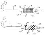
- FIG. 2illustrates the same balloon 14 coated with a “waffle” pattern coating 15 of the present invention coated over balloon wall 13 .
- FIG. 3illustrates the same balloon construction with another embodiment of the coating 16 of the present invention having a different pattern than that exhibited in FIG. 2 .
- the pattern in this diagramis a “stripe” pattern wherein the stripes run diagonally around the circumference of the balloon.
- FIG. 4illustrates the same balloon construction as in FIGS. 2 and 3 with yet another embodiment of a the coating 17 of the present invention having yet a different pattern than exhibited in the other figures.
- This embodimentillustrates a more solid coating which has circular perforations spaced at a uniform distance from one another. The size of the perforations may be varied.
- FIG. 5illustrates a balloon 20 in its uninflated state, and having a “stripe” pattern coating 18 of a polyurethane polymer, also referred to as a “shape memory polymer.”
- This pattern ofhas the stripes running longitudinally with the balloon whereas the pattern illustrated in FIG. 3 exhibits stripes running diagonally around the circumference of the balloon 20 .
- the polyurethane polymer utilized in this embodimentis available from Mitsubishi Heavy Industries, Ltd in Tokyo, Japan, under the tradename of SMP-3510.
- the balloon 20has an inner wire lumen 30 for delivery of the inflation media.
- the balloonexhibits a pinhole 50 left of center and beneath a coated section of the balloon.
- FIG. 6illustrates the same balloon 20 as shown in FIG. 5 during inflation.
- Inflation mediumcan be seen venting from out the edges of the coated section. Desirably, no aneurysm is formed in the coating because the inflation medium can easily escape.
- the inflation media 55is exiting through the pinhose 50 and can be seen venting out the sides of the discontinuous stripe coating 18 on balloon 20 .
- the large inverted water droplet 60 seen in the center from of the photographis forming as a result of the inflation media 55 flowing out of the pinhole 50 .
- Both the stream of inflation media 55 and the droplet 60are on the same side of the balloon 20 . Such droplet formation would not be exhibited were the balloon in an aqueous environment such as a vessel of a patient but such fluid would be carried away in the blood.
- FIG. 7illustrates a balloon 20 having a continuous coating 19 of polyurethane polymer, SMP-3510, available from Mistubishi Heavy Industries, Ltd, in its inflated state.
- An aneurysm 40is formed in the coating.
- Inner wire lumen 30is for inflation media delivery.
- any pattern wherein there is discontinuity in the coatingmay alleviate the formation of pinholes which may ultimately lead to aneurysms in the balloon construction, and to damage to the patients vessels.
- the balloonsmay be constructed of thermoplastic polymeric materials including thermoplastic elastomers, i.e. block copolymers; copolymers and terpolymers of ethylene; homopolymers, copolymers and terpolymers of propylene; ethylene ⁇ -olefins; polyesters; polyamides; polyurethanes; polycarbonates, vinyl copolymers; ionomer materials and so forth. More specifically, materials such as nylon, Selar®, polyether-polyester block copolymers (i.e.
- Thermosetting materialssuch as polyimides may also be utilized.
- the balloon wallmay be noncompliant or compliant.
- Noncompliant balloonsare formed from relatively stiff materials including polyethyleneterephthalate (PET), high density polyethylene, polyamides, polycarbonates and stiff polyurethanes, and so forth.
- PETpolyethyleneterephthalate
- the balloon wallmay also be compliant and made of materials such as polyvinyl chloride, polyethylene, polyester copolymers, polyolefin copolymers and so forth.
- the present inventionprovides a particular advantage when the balloon wall is made of a stiff, noncompliant material. Such materials tend to scratch more easily, especially if a fold occurs in the balloon.
- Some specific preferred balloon materialsinclude polyether block amides, such as Pebax® 7033 or 7233; polyester block ethers such as Arnitel® EM 40; polyethylene terephthalate (0.64 to 0.8 IV PET); and nylon.
- polyether block amidessuch as Pebax® 7033 or 7233
- polyester block etherssuch as Arnitel® EM 40
- polyethylene terephthalate(0.64 to 0.8 IV PET
- nylonnylon.
- a typical method of balloon formationinvolves first extruding a tubular preform, and subsequently blowing the tubular preform into a balloon.
- the balloonhas what is referred to as a body, at least one cone portion, and at least one waist portion.
- Suitable balloon forming techniqueswhich may be employed are well known in the art and may be carried out in any conventional manner with conventional extrusion and blowing techniques. Such techniques for balloon formation are discussed in U.S. Pat. No. 4,490,421 to Levy and in U.S. Pat. No. 5,348,538 issued Sep. 20, 1994 to Wang et al. herein incorporated by reference.
- the balloonhas a coating over the balloon wall.
- the coatingwill be on the balloon body.
- the cones and the waist portion(s)may also be coated.
- Any thermoplastic polymeric material which is dissolvable in solvent, and which improves the durability of the balloonmay be utilized.
- the coating polymeris desirably sufficiently flexible and elastic at body temperature and has only a minor, if any, impact on the compliance characteristics of the balloon.
- the coating materialpreferably does not adversely affect the compliance characteristics of the balloon itself.
- the polymeric coatingmay also preferably have some surface tack for certain applications including stent delivery catheters. A certain amount of tack may help hold the stent more securely when the stent is in the crimped down position.
- the polymersmay be thermoplastic or thermoset polymeric materials.
- Thermoplastic materials useful to the present inventioninclude any type of material from which the balloons themselves may be produced, as well as many others. Examples of such materials include vinyl polymers, fluorinated and chlorinated polymers, polyolefins, polyurethanes, polystyrene, polyesters, nylons, polyamides, polycarbonates, polyacrylates, poly(meth)acrylates, copolymerized versions, and so forth.
- Rubbery block copolymersinclude those having the general configuration of linear, radial, star, Y-block, multiblock and so forth.
- the coating materialmay include polyvinyl chloride; polyethylene terephthalate; polyethylene homopolymers; styrene-butadiene-styrene block copolymers; styrene-ethylene/butylene-styrene block copolymers; styrene-ethylene/propylene-styrene block copolymers; styrene-isoprene-styrene block copolymers; polyester elastomers, polyether-block amides; copolymers of ethylene and vinyl acetate, n-butyl acrylate, methylacrylate; interpolymers of ethylene and at least one alpha-olefin; and so forth.
- thermoplastic polymers useful for the coatingare the thermoplastic polyurethane polymers.
- Thermosetting polymershave functional moieties which are capable of crosslinking with other functional moieties.
- Thermosetting materialsinclude polyurethanes formed from an isocyanate and a polyol; acrylics; acrylates; methacrylates; epoxies; unsaturated polyesters; silicones having hydrolyzable acetate groups; polysulfides; cyanoacrylates; formaldehydes condensed with urea, phenol, resorcinol, melamine for instance, and so forth.
- Thermosetting compositionsrefer to crosslinkable compositions, even those that do not necessarily require elevated temperatures to initiate the chemical reaction. It is preferable to the present invention to initiate polymerization or cure using electron beam or ultraviolet radiation.
- a polyurethane polymeris utilized.
- the glass transition temperature of these polyurethane polymersmay be adjusted by changing the molar ratio of diisocyanate, polyol and chain extender. Glass transition temperatures may also be varied by changing the polyol itself.
- An example of a polyurethane polymeris SMP-3510 available from Mitsubishi Heavy Industries, Ltd. These polymers are also referred to as “shape memory polymers.”
- Water based polymersmay also be utilized including polyurethane dispersions and emulsion polymers such as acrylics, vinyl acetate homopolymers, vinyl acrylic copolymers, vinyl acetate ethylene copolymers, and so forth.
- a preferable water base coatingis a urethane.
- the coating of the present inventionis a noncontinuous coating and may be referred to as a porous coating or pattern coating.
- Pattern coatingcan be achieved in a number of ways including roll coating, screen printing, pad printing, spraying and so forth.
- the coating application headi.e. roll or pad, for instance, will have dimples or indentations which result in a noncontinuous coating being applied to the balloon.
- the patternis preferably substantially uniform.
- a preferable coating pattern which may be obtained using a pad printing methodmay be referred to as a waffle pattern wherein the shape of the indentation may be any shape provided the repeating pattern is substantially uniform. Typical indentation shapes are square or round. Such a pattern may be found in FIG. 2 or FIG. 3 .
- Sprayingmay also be employed to achieve a pattern type of coating to the balloon but will result in a much less uniform noncontinuous coating.
- thermoplastic polymersit will be preferable to first dissolve the polymer in a solvent or a blend of solvents prior to applying the coating to the balloon.
- suitable solventsinclude acetone, methyl acetate, dimethylacetate, ethyl acetate, dioxane, alcohols, chloroform, methylene chloride, acetonitrile, toluene, methyl ethyl ketone, tetrahydrofuran, dimethylformamide, dimethylsulfoxide, cyclohexanone, acetates including butyl acetate, dimethylacetate, 1-methoxy-2-propanolacetate, and so forth, and mixtures thereof.
- the polymermay usually be dissolved in the solvent by shaking or by stirring at room temperature, but if necessary, an elevated temperature, such as about 40-50° C., may be utilized to dissolve the polymer.
- the coating thickness on the balloonmay be adjusted by changing the concentration of the polymer solution.
- the concentration of polymer in solutionwill be about 1% to 60%, more preferably about 5% to about 55%, and most preferably about 10% to 50%.
- the concentration of the polymer in solution to some degreedepends on the particular application with which the medical device will be coated. Some applications require lower viscosity solutions than others. For instance, spray applications may require polymer concentrations of about 10% to about 20% while pad printing may require higher polymer concentrations of about 20% to about 50%.
- the solventis then desirably evaporated from the coating, leaving only the polymer remaining. This may be accomplished either at ambient temperatures, or the evaporation process by be accelerated by drying at elevated temperatures.
- Thermoplastic polymersbecome molten and flowable when subjected to heat.
- the polymers useful to the present inventionpreferably have high tensile strength.
- Such high strength polymersalso typically have high molecular weights and would require quite high temperatures of over 150° C. to lower the viscosity enough to apply using conventional coating techniques.
- the balloon materials, being in thin film,would be sensitive to such high temperatures and it would therefore be detrimental to apply the coating to the balloon with high temperatures.
- the coatingis preferably applied when the balloon is in its inflated state. Coverage of the coating is preferably limited to the body of the balloon, and is not found on the waist or cone portions of the balloon.
- a particularly preferred method of applicationis pad printing.
- the padsare typically formed from a soft silicone rubber. Such materials would have less of a tendency to cause any abrasions in the balloon material.
- the padpicks up the image or pattern to be printed from an etched plate, and then transfers the coating pattern to the balloon. Using this method, the coating may be wrapped around curved surfaces easily. The shape and design of the pattern can be easily varied.
- One preferred patternmay be referred to as a “waffle” pattern in which the coating actually resembles a waffle.
- Film thickness of the coatingis preferably from about 0.1 to about 3 mils, more preferably from about 0.1 to 1.5 mils, and most preferably from about 0.2 to 1 mil.
- the coatingimproves the durability of the balloon by making it more abrasion, scratch and puncture resistance. Furthermore, should an abrasion, scratch or puncture occur in the underlying balloon wall, the discontinuous nature of the outer protective coating prevents it from inflating on its own and pulling away from the balloon wall, which in turn prevents bulging or bubbles which can cause dissection of blood vessels or arteries.
- a particular problem with the formation of such balloonsis the occurrence of what is referred to in the industry as “pinholes.” Inflation medium escapes through these pinholes causing the outer coating to inflate on its own forming a bulge or bubble which can cause the dissection of a blood vessel of artery.
- the present inventionovercomes such problems.
- Example 1The following ingredients were utilized in preparing the coating composition for Example 1 and for Comparative Example A:
- the coating composition shown abovewas brushed on a dilatation balloon in a striped pattern. This pattern was accomplished by masking off sections of the balloon and brushing on the coating so that the masked sections had no coating.
- the coatingwas dried and the toluene, DMAC and THF were evaporated off leaving only the polyurethane, SMP-3510 on the balloon.
- the balloonwhich had a pinhole in its wall, was then inflated. The pinhole was in the center of a coated section of balloon.
- the inflation mediumflowed out of the pinhole and vented out of the sides of the coated section so that no aneurysm occurred in the coating.
- FIG. 5illustrates the coated balloon in its uninflated state.
- the pinholeis right of center and located beneath a coated section of the balloon.
- FIG. 6illustrates the coated balloon in its inflated state.
- the inflation mediumis venting around the sides of the coating as desired. No aneurysm is formed in the coating.
- a continuous coating of the composition shown abovewas brushed on a dilatation balloon.
- the coatingwas dried, evaporating off the toluene, DMAC and THF and leaving only the polyurethane, SMP-3510 on the balloon.
- the balloonhad a pinhole in its wall, and upon inflation, a large bubble or aneurysm occurred in the coating as is shown in FIG. 7 .
- a coating comprising a polyurethane polymer in a mixture of solvents available from Creative Materials under the tradename of CMI 118-43was pad printed on a catheter balloon in a waffle pattern so as to eliminate the possibility of pinhole formation.
Landscapes
- Health & Medical Sciences (AREA)
- Life Sciences & Earth Sciences (AREA)
- Animal Behavior & Ethology (AREA)
- Veterinary Medicine (AREA)
- Heart & Thoracic Surgery (AREA)
- Public Health (AREA)
- General Health & Medical Sciences (AREA)
- Biophysics (AREA)
- Biomedical Technology (AREA)
- Hematology (AREA)
- Anesthesiology (AREA)
- Engineering & Computer Science (AREA)
- Pulmonology (AREA)
- Child & Adolescent Psychology (AREA)
- Epidemiology (AREA)
- Materials For Medical Uses (AREA)
Abstract
Description
Claims (14)
Priority Applications (6)
| Application Number | Priority Date | Filing Date | Title |
|---|---|---|---|
| US09/477,236US7479128B1 (en) | 2000-01-04 | 2000-01-04 | Protective coatings for medical devices |
| DE60110745TDE60110745T2 (en) | 2000-01-04 | 2001-01-02 | PROTECTIVE LAYER FOR MEDICAL DEVICES |
| PCT/US2001/000088WO2001049337A1 (en) | 2000-01-04 | 2001-01-02 | Protective coatings for medical devices |
| EP01939974AEP1244479B1 (en) | 2000-01-04 | 2001-01-02 | Protective coatings for medical devices |
| AT01939974TATE295191T1 (en) | 2000-01-04 | 2001-01-02 | PROTECTIVE LAYER FOR MEDICAL DEVICES |
| US12/353,706US8251962B2 (en) | 2000-01-04 | 2009-01-14 | Protective coatings for medical devices |
Applications Claiming Priority (1)
| Application Number | Priority Date | Filing Date | Title |
|---|---|---|---|
| US09/477,236US7479128B1 (en) | 2000-01-04 | 2000-01-04 | Protective coatings for medical devices |
Related Child Applications (1)
| Application Number | Title | Priority Date | Filing Date |
|---|---|---|---|
| US12/353,706ContinuationUS8251962B2 (en) | 2000-01-04 | 2009-01-14 | Protective coatings for medical devices |
Publications (1)
| Publication Number | Publication Date |
|---|---|
| US7479128B1true US7479128B1 (en) | 2009-01-20 |
Family
ID=23895088
Family Applications (2)
| Application Number | Title | Priority Date | Filing Date |
|---|---|---|---|
| US09/477,236Expired - Fee RelatedUS7479128B1 (en) | 2000-01-04 | 2000-01-04 | Protective coatings for medical devices |
| US12/353,706Expired - Fee RelatedUS8251962B2 (en) | 2000-01-04 | 2009-01-14 | Protective coatings for medical devices |
Family Applications After (1)
| Application Number | Title | Priority Date | Filing Date |
|---|---|---|---|
| US12/353,706Expired - Fee RelatedUS8251962B2 (en) | 2000-01-04 | 2009-01-14 | Protective coatings for medical devices |
Country Status (5)
| Country | Link |
|---|---|
| US (2) | US7479128B1 (en) |
| EP (1) | EP1244479B1 (en) |
| AT (1) | ATE295191T1 (en) |
| DE (1) | DE60110745T2 (en) |
| WO (1) | WO2001049337A1 (en) |
Cited By (6)
| Publication number | Priority date | Publication date | Assignee | Title |
|---|---|---|---|---|
| US20060034884A1 (en)* | 2004-08-10 | 2006-02-16 | Stenzel Eric B | Coated medical device having an increased coating surface area |
| US20060171982A1 (en)* | 2005-02-03 | 2006-08-03 | Timm Mary J | Deforming surface of drug eluting coating to alter drug release profile of a medical device |
| US20060184112A1 (en)* | 2005-02-17 | 2006-08-17 | Horn Daniel J | Medical devices |
| US20070293761A1 (en)* | 2004-04-02 | 2007-12-20 | Koninklijke Philips Electronics, N.V. | Ultrasonic Probe Volume Compensation System |
| US20090124969A1 (en)* | 2000-01-04 | 2009-05-14 | Boston Scientific Scimed, Inc. | Protective Coatings for Medical Devices |
| US20140276457A1 (en)* | 2013-03-14 | 2014-09-18 | Baxter International Inc. | Drip chamber with hydrophobic interior surface |
Families Citing this family (13)
| Publication number | Priority date | Publication date | Assignee | Title |
|---|---|---|---|---|
| US6841213B2 (en)* | 2002-12-27 | 2005-01-11 | Scimed Life Systems, Inc | Fiber pattern printing |
| DE10351150A1 (en)* | 2003-11-03 | 2005-05-25 | Blue Membranes Gmbh | Method and device for applying a defined amount of a coating material to the surface of a body to be coated |
| JP4443278B2 (en)* | 2004-03-26 | 2010-03-31 | テルモ株式会社 | Catheter with expansion body |
| DE102005007596A1 (en)* | 2005-02-18 | 2006-08-24 | Breeze Medical, Inc., Boca Raton | Coating, manufacturing method and method for applying a coating to a medical instrument and medical instrument |
| US8876763B2 (en) | 2005-11-01 | 2014-11-04 | Boston Scientific Scimed, Inc. | Composite balloon |
| PL2083873T3 (en)* | 2006-11-17 | 2011-03-31 | Essity Hygiene & Health Ab | Absorbent articles comprising an organic zinc salt and an anti-bacterial agent or alkali metal chloride or alkaline earth metal chloride |
| DE102007036685A1 (en) | 2007-08-03 | 2009-02-05 | Innora Gmbh | Improved drug-coated medical devices their manufacture and use |
| US20090318863A1 (en)* | 2008-06-18 | 2009-12-24 | Boston Scientific Scimed, Inc. | Functional Balloon With Built in Lubricity or Drug Delivery System |
| WO2011116303A1 (en) | 2010-03-19 | 2011-09-22 | Micropen Technologies Corporation | Thermocouple device |
| US9730726B2 (en) | 2011-10-07 | 2017-08-15 | W. L. Gore & Associates, Inc. | Balloon assemblies having controllably variable topographies |
| US9669194B2 (en) | 2013-03-14 | 2017-06-06 | W. L. Gore & Associates, Inc. | Conformable balloon devices and methods |
| EP3091922B1 (en) | 2014-01-06 | 2018-10-17 | Boston Scientific Scimed, Inc. | Tear resistant flex circuit assembly |
| WO2021127609A1 (en) | 2019-12-20 | 2021-06-24 | Surmodics, Inc. | Universal scoring device |
Citations (41)
| Publication number | Priority date | Publication date | Assignee | Title |
|---|---|---|---|---|
| US4490421A (en) | 1983-07-05 | 1984-12-25 | E. I. Du Pont De Nemours And Company | Balloon and manufacture thereof |
| US4702252A (en)* | 1983-10-13 | 1987-10-27 | Smiths Industries Public Limited Company | Catheters |
| EP0380102A1 (en) | 1989-01-26 | 1990-08-01 | Advanced Cardiovascular Systems, Inc. | Vascular catheter with durable lubricious coating |
| US5041100A (en) | 1989-04-28 | 1991-08-20 | Cordis Corporation | Catheter and hydrophilic, friction-reducing coating thereon |
| US5061424A (en) | 1991-01-22 | 1991-10-29 | Becton, Dickinson And Company | Method for applying a lubricious coating to an article |
| US5077352A (en)* | 1990-04-23 | 1991-12-31 | C. R. Bard, Inc. | Flexible lubricious organic coatings |
| US5100381A (en) | 1989-11-13 | 1992-03-31 | Scimed Life Systems, Inc. | Angioplasty catheter |
| US5135474A (en) | 1990-08-03 | 1992-08-04 | University Of Medicine And Dentistry Of New Jersey | Hepatic bypass catheter |
| US5135381A (en) | 1989-04-17 | 1992-08-04 | Jetra Engineering Pty. Limited | Cutting and trimming plastic pot |
| US5304121A (en)* | 1990-12-28 | 1994-04-19 | Boston Scientific Corporation | Drug delivery system making use of a hydrogel polymer coating |
| US5348538A (en) | 1992-09-29 | 1994-09-20 | Scimed Life Systems, Inc. | Shrinking balloon catheter having nonlinear or hybrid compliance curve |
| WO1994027665A1 (en) | 1993-06-02 | 1994-12-08 | Scimed Life Systems, Inc. | Selective arrangement of lubricous coatings on balloon catheters |
| US5383806A (en) | 1993-03-30 | 1995-01-24 | Continental American Corporation | Inflatable balloons with anti-blooming and anti-fogging coatings |
| US5423745A (en) | 1988-04-28 | 1995-06-13 | Research Medical, Inc. | Irregular surface balloon catheters for body passageways and methods of use |
| WO1995033422A1 (en) | 1994-06-06 | 1995-12-14 | Meadox Medicals, Inc. | A catheter with stent and method for the production of a catheter with stent |
| US5487730A (en) | 1992-12-30 | 1996-01-30 | Medtronic, Inc. | Balloon catheter with balloon surface retention means |
| US5490839A (en)* | 1993-09-20 | 1996-02-13 | Scimed Life Systems, Inc. | Catheter balloon with retraction coating |
| US5496276A (en) | 1993-09-20 | 1996-03-05 | Scimed Life Systems, Inc. | Catheter balloon with retraction coating |
| US5503631A (en) | 1992-10-09 | 1996-04-02 | Terumo Kabushiki Kaisha | Lubricious catheter balloon for vasodilation |
| US5556383A (en) | 1994-03-02 | 1996-09-17 | Scimed Lifesystems, Inc. | Block copolymer elastomer catheter balloons |
| US5613979A (en) | 1989-11-29 | 1997-03-25 | Cordis Corporation | Puncture resistant balloon catheter |
| US5653690A (en)* | 1992-12-30 | 1997-08-05 | Medtronic, Inc. | Catheter having a balloon with retention enhancement |
| US5693088A (en) | 1993-11-08 | 1997-12-02 | Lazarus; Harrison M. | Intraluminal vascular graft |
| US5693014A (en) | 1993-08-23 | 1997-12-02 | Boston Scientific Corporation | Balloon catheter |
| US5714110A (en) | 1993-09-20 | 1998-02-03 | Scimed Life Systems, Inc. | Process improvements for preparing catheter balloons |
| US5720735A (en) | 1997-02-12 | 1998-02-24 | Dorros; Gerald | Bifurcated endovascular catheter |
| US5738901A (en) | 1993-09-20 | 1998-04-14 | Scimed Life Systems, Inc. | Catheter balloon with retraction coating |
| US5743963A (en) | 1995-07-31 | 1998-04-28 | Becton Dickinson And Company | Apparatus and method for coating of objects using a porous resilient matrix |
| US5746745A (en) | 1993-08-23 | 1998-05-05 | Boston Scientific Corporation | Balloon catheter |
| US5766158A (en) | 1995-02-06 | 1998-06-16 | Surface Solutions Laboratories, Inc. | Medical apparatus with scratch-resistant coating and method of making same |
| US5766204A (en)* | 1995-06-07 | 1998-06-16 | Metastent Incorporated | Curable fiber composite stent and delivery system |
| US5797877A (en) | 1993-10-01 | 1998-08-25 | Boston Scientific Corporation | Medical device balloons containing thermoplastic elastomers |
| EP0872253A2 (en) | 1997-04-16 | 1998-10-21 | Smiths Industries Public Limited Company | Cuffed medico-surgical tubes |
| US5830182A (en) | 1994-03-02 | 1998-11-03 | Scimed Life Systems, Inc. | Block copolymer elastomer catheter balloons |
| US5853481A (en) | 1995-07-31 | 1998-12-29 | Becton Dickinson And Company | Apparatus for coating of objects using a porous resilient matrix |
| US5860998A (en) | 1996-11-25 | 1999-01-19 | C. R. Bard, Inc. | Deployment device for tubular expandable prosthesis |
| US5868779A (en) | 1997-08-15 | 1999-02-09 | Ruiz; Carlos E. | Apparatus and methods for dilating vessels and hollow-body organs |
| US5876374A (en) | 1992-11-02 | 1999-03-02 | Localmed, Inc. | Catheter sleeve for use with a balloon catheter |
| WO1999059649A1 (en) | 1998-05-18 | 1999-11-25 | Boston Scientific Ltd. | Localized delivery of drug agents |
| US6176849B1 (en)* | 1999-05-21 | 2001-01-23 | Scimed Life Systems, Inc. | Hydrophilic lubricity coating for medical devices comprising a hydrophobic top coat |
| US6273878B1 (en)* | 1998-02-19 | 2001-08-14 | Percusurge, Inc | Shaft for medical catheters |
Family Cites Families (5)
| Publication number | Priority date | Publication date | Assignee | Title |
|---|---|---|---|---|
| CA1232814A (en)* | 1983-09-16 | 1988-02-16 | Hidetoshi Sakamoto | Guide wire for catheter |
| US4777951A (en)* | 1986-09-19 | 1988-10-18 | Mansfield Scientific, Inc. | Procedure and catheter instrument for treating patients for aortic stenosis |
| JPH0783761B2 (en)* | 1990-10-04 | 1995-09-13 | テルモ株式会社 | Medical equipment |
| US5599298A (en)* | 1993-12-30 | 1997-02-04 | Boston Scientific Corporation | Bodily sample collection balloon catheter method |
| US7479128B1 (en)* | 2000-01-04 | 2009-01-20 | Boston Scientific Scimed, Inc. | Protective coatings for medical devices |
- 2000
- 2000-01-04USUS09/477,236patent/US7479128B1/ennot_activeExpired - Fee Related
- 2001
- 2001-01-02EPEP01939974Apatent/EP1244479B1/ennot_activeExpired - Lifetime
- 2001-01-02WOPCT/US2001/000088patent/WO2001049337A1/enactiveIP Right Grant
- 2001-01-02DEDE60110745Tpatent/DE60110745T2/ennot_activeExpired - Lifetime
- 2001-01-02ATAT01939974Tpatent/ATE295191T1/ennot_activeIP Right Cessation
- 2009
- 2009-01-14USUS12/353,706patent/US8251962B2/ennot_activeExpired - Fee Related
Patent Citations (45)
| Publication number | Priority date | Publication date | Assignee | Title |
|---|---|---|---|---|
| US4490421A (en) | 1983-07-05 | 1984-12-25 | E. I. Du Pont De Nemours And Company | Balloon and manufacture thereof |
| US4702252A (en)* | 1983-10-13 | 1987-10-27 | Smiths Industries Public Limited Company | Catheters |
| US5423745A (en) | 1988-04-28 | 1995-06-13 | Research Medical, Inc. | Irregular surface balloon catheters for body passageways and methods of use |
| EP0380102A1 (en) | 1989-01-26 | 1990-08-01 | Advanced Cardiovascular Systems, Inc. | Vascular catheter with durable lubricious coating |
| US5135381A (en) | 1989-04-17 | 1992-08-04 | Jetra Engineering Pty. Limited | Cutting and trimming plastic pot |
| US5041100A (en) | 1989-04-28 | 1991-08-20 | Cordis Corporation | Catheter and hydrophilic, friction-reducing coating thereon |
| US5100381A (en) | 1989-11-13 | 1992-03-31 | Scimed Life Systems, Inc. | Angioplasty catheter |
| US5613979A (en) | 1989-11-29 | 1997-03-25 | Cordis Corporation | Puncture resistant balloon catheter |
| US5077352A (en)* | 1990-04-23 | 1991-12-31 | C. R. Bard, Inc. | Flexible lubricious organic coatings |
| US5135474A (en) | 1990-08-03 | 1992-08-04 | University Of Medicine And Dentistry Of New Jersey | Hepatic bypass catheter |
| US5304121A (en)* | 1990-12-28 | 1994-04-19 | Boston Scientific Corporation | Drug delivery system making use of a hydrogel polymer coating |
| US5061424A (en) | 1991-01-22 | 1991-10-29 | Becton, Dickinson And Company | Method for applying a lubricious coating to an article |
| US5348538A (en) | 1992-09-29 | 1994-09-20 | Scimed Life Systems, Inc. | Shrinking balloon catheter having nonlinear or hybrid compliance curve |
| US5503631A (en) | 1992-10-09 | 1996-04-02 | Terumo Kabushiki Kaisha | Lubricious catheter balloon for vasodilation |
| US5876374A (en) | 1992-11-02 | 1999-03-02 | Localmed, Inc. | Catheter sleeve for use with a balloon catheter |
| US5487730A (en) | 1992-12-30 | 1996-01-30 | Medtronic, Inc. | Balloon catheter with balloon surface retention means |
| US5720726A (en) | 1992-12-30 | 1998-02-24 | Medtronic, Inc. | Balloon catheter having retention enhancements on the balloon |
| US5653690A (en)* | 1992-12-30 | 1997-08-05 | Medtronic, Inc. | Catheter having a balloon with retention enhancement |
| US5383806A (en) | 1993-03-30 | 1995-01-24 | Continental American Corporation | Inflatable balloons with anti-blooming and anti-fogging coatings |
| WO1994027665A1 (en) | 1993-06-02 | 1994-12-08 | Scimed Life Systems, Inc. | Selective arrangement of lubricous coatings on balloon catheters |
| US5693014A (en) | 1993-08-23 | 1997-12-02 | Boston Scientific Corporation | Balloon catheter |
| US6010480A (en)* | 1993-08-23 | 2000-01-04 | Boston Scientific Corporation | Balloon catheter |
| US5746745A (en) | 1993-08-23 | 1998-05-05 | Boston Scientific Corporation | Balloon catheter |
| US5738901A (en) | 1993-09-20 | 1998-04-14 | Scimed Life Systems, Inc. | Catheter balloon with retraction coating |
| US5496276A (en) | 1993-09-20 | 1996-03-05 | Scimed Life Systems, Inc. | Catheter balloon with retraction coating |
| US5714110A (en) | 1993-09-20 | 1998-02-03 | Scimed Life Systems, Inc. | Process improvements for preparing catheter balloons |
| US5490839A (en)* | 1993-09-20 | 1996-02-13 | Scimed Life Systems, Inc. | Catheter balloon with retraction coating |
| US5797877A (en) | 1993-10-01 | 1998-08-25 | Boston Scientific Corporation | Medical device balloons containing thermoplastic elastomers |
| US5693088A (en) | 1993-11-08 | 1997-12-02 | Lazarus; Harrison M. | Intraluminal vascular graft |
| US5830182A (en) | 1994-03-02 | 1998-11-03 | Scimed Life Systems, Inc. | Block copolymer elastomer catheter balloons |
| US5556383A (en) | 1994-03-02 | 1996-09-17 | Scimed Lifesystems, Inc. | Block copolymer elastomer catheter balloons |
| WO1995033422A1 (en) | 1994-06-06 | 1995-12-14 | Meadox Medicals, Inc. | A catheter with stent and method for the production of a catheter with stent |
| US5766158A (en) | 1995-02-06 | 1998-06-16 | Surface Solutions Laboratories, Inc. | Medical apparatus with scratch-resistant coating and method of making same |
| US5766204A (en)* | 1995-06-07 | 1998-06-16 | Metastent Incorporated | Curable fiber composite stent and delivery system |
| US5773081A (en) | 1995-07-31 | 1998-06-30 | Becton Dickinson And Company | Method for coating of objects using a rotating resilient matrix |
| US5853481A (en) | 1995-07-31 | 1998-12-29 | Becton Dickinson And Company | Apparatus for coating of objects using a porous resilient matrix |
| US5863614A (en) | 1995-07-31 | 1999-01-26 | Becton Dickinson And Company | Method for coating objects with a porous resilient matrix |
| US5743963A (en) | 1995-07-31 | 1998-04-28 | Becton Dickinson And Company | Apparatus and method for coating of objects using a porous resilient matrix |
| US5860998A (en) | 1996-11-25 | 1999-01-19 | C. R. Bard, Inc. | Deployment device for tubular expandable prosthesis |
| US5720735A (en) | 1997-02-12 | 1998-02-24 | Dorros; Gerald | Bifurcated endovascular catheter |
| EP0872253A2 (en) | 1997-04-16 | 1998-10-21 | Smiths Industries Public Limited Company | Cuffed medico-surgical tubes |
| US5868779A (en) | 1997-08-15 | 1999-02-09 | Ruiz; Carlos E. | Apparatus and methods for dilating vessels and hollow-body organs |
| US6273878B1 (en)* | 1998-02-19 | 2001-08-14 | Percusurge, Inc | Shaft for medical catheters |
| WO1999059649A1 (en) | 1998-05-18 | 1999-11-25 | Boston Scientific Ltd. | Localized delivery of drug agents |
| US6176849B1 (en)* | 1999-05-21 | 2001-01-23 | Scimed Life Systems, Inc. | Hydrophilic lubricity coating for medical devices comprising a hydrophobic top coat |
Cited By (14)
| Publication number | Priority date | Publication date | Assignee | Title |
|---|---|---|---|---|
| US8251962B2 (en) | 2000-01-04 | 2012-08-28 | Boston Scientific Scimed, Inc. | Protective coatings for medical devices |
| US20090124969A1 (en)* | 2000-01-04 | 2009-05-14 | Boston Scientific Scimed, Inc. | Protective Coatings for Medical Devices |
| US8353838B2 (en)* | 2004-04-02 | 2013-01-15 | Koninklijke Philips Electronics N.V. | Ultrasonic probe volume compensation system |
| US20070293761A1 (en)* | 2004-04-02 | 2007-12-20 | Koninklijke Philips Electronics, N.V. | Ultrasonic Probe Volume Compensation System |
| US20060034884A1 (en)* | 2004-08-10 | 2006-02-16 | Stenzel Eric B | Coated medical device having an increased coating surface area |
| US8221824B2 (en) | 2005-02-03 | 2012-07-17 | Boston Scientific Scimed, Inc. | Deforming surface of drug eluting coating to alter drug release profile of a medical device |
| US20060171982A1 (en)* | 2005-02-03 | 2006-08-03 | Timm Mary J | Deforming surface of drug eluting coating to alter drug release profile of a medical device |
| US8048028B2 (en)* | 2005-02-17 | 2011-11-01 | Boston Scientific Scimed, Inc. | Reinforced medical balloon |
| US20060184112A1 (en)* | 2005-02-17 | 2006-08-17 | Horn Daniel J | Medical devices |
| US8852146B2 (en) | 2005-02-17 | 2014-10-07 | Boston Scientific Scimed, Inc. | Reinforced medical balloon |
| US20140276457A1 (en)* | 2013-03-14 | 2014-09-18 | Baxter International Inc. | Drip chamber with hydrophobic interior surface |
| US9352081B2 (en)* | 2013-03-14 | 2016-05-31 | Baxter International Inc. | Drip chamber with hydrophobic interior surface |
| US10314972B2 (en)* | 2013-03-14 | 2019-06-11 | Baxter International Inc. | Drip chamber with hydrophobic interior surface |
| US11013860B2 (en) | 2013-03-14 | 2021-05-25 | Baxter International Inc. | Drip chamber with hydrophobic interior surface |
Also Published As
| Publication number | Publication date |
|---|---|
| US20090124969A1 (en) | 2009-05-14 |
| DE60110745D1 (en) | 2005-06-16 |
| ATE295191T1 (en) | 2005-05-15 |
| US8251962B2 (en) | 2012-08-28 |
| EP1244479B1 (en) | 2005-05-11 |
| WO2001049337A1 (en) | 2001-07-12 |
| DE60110745T2 (en) | 2006-02-23 |
| EP1244479A1 (en) | 2002-10-02 |
Similar Documents
| Publication | Publication Date | Title |
|---|---|---|
| US8251962B2 (en) | Protective coatings for medical devices | |
| US6528150B2 (en) | Coating gradient for lubricious coatings on balloon catheters | |
| US5496276A (en) | Catheter balloon with retraction coating | |
| US5738901A (en) | Catheter balloon with retraction coating | |
| US5490839A (en) | Catheter balloon with retraction coating | |
| US6746425B1 (en) | Medical balloon | |
| US8979886B2 (en) | Medical balloon and method of making the same | |
| US6458138B1 (en) | Selective coating of a balloon catheter with lubricious material for stent deployment | |
| JP3554705B2 (en) | Balloon made of liquid crystal polymer blend | |
| JP3053029B2 (en) | Vascular dilatation catheter balloon | |
| US6124007A (en) | Laminate catheter balloons with additive burst strength and methods for preparation of same | |
| EP2049181B1 (en) | Catheter balloons with integrated non-distensible seals | |
| JP3577082B2 (en) | Medical device balloon made of thermoplastic elastomer | |
| US9592369B2 (en) | Balloon catheter | |
| EP0592870A1 (en) | Process for preparing functionally coated expanded products from expandable tubing and the expanded products produced thereby | |
| US20040197501A1 (en) | Catheter balloon formed of a polyurethane of p-phenylene diisocyanate and polycaprolactone | |
| JPH10277157A (en) | Balloon dilatation catheter and method of manufacturing the same | |
| US20170354524A1 (en) | Multilayer balloons | |
| WO1998050087A1 (en) | Improved medical device having desirable combination of properties and method of making same |
Legal Events
| Date | Code | Title | Description |
|---|---|---|---|
| AS | Assignment | Owner name:BOSTON SCIENTIFIC SCIMED, INC., MINNESOTA Free format text:CHANGE OF NAME;ASSIGNOR:SCIMED LIFE SYSTEMS, INC.;REEL/FRAME:018505/0868A Effective date:20050101 Owner name:BOSTON SCIENTIFIC SCIMED, INC., MINNESOTA Free format text:CHANGE OF NAME;ASSIGNOR:SCIMED LIFE SYSTEMS, INC.;REEL/FRAME:018505/0868 Effective date:20050101 Owner name:BOSTON SCIENTIFIC SCIMED, INC.,MINNESOTA Free format text:CHANGE OF NAME;ASSIGNOR:SCIMED LIFE SYSTEMS, INC.;REEL/FRAME:018505/0868 Effective date:20050101 | |
| STCF | Information on status: patent grant | Free format text:PATENTED CASE | |
| FPAY | Fee payment | Year of fee payment:4 | |
| FPAY | Fee payment | Year of fee payment:8 | |
| FEPP | Fee payment procedure | Free format text:MAINTENANCE FEE REMINDER MAILED (ORIGINAL EVENT CODE: REM.); ENTITY STATUS OF PATENT OWNER: LARGE ENTITY | |
| LAPS | Lapse for failure to pay maintenance fees | Free format text:PATENT EXPIRED FOR FAILURE TO PAY MAINTENANCE FEES (ORIGINAL EVENT CODE: EXP.); ENTITY STATUS OF PATENT OWNER: LARGE ENTITY | |
| STCH | Information on status: patent discontinuation | Free format text:PATENT EXPIRED DUE TO NONPAYMENT OF MAINTENANCE FEES UNDER 37 CFR 1.362 | |
| FP | Lapsed due to failure to pay maintenance fee | Effective date:20210120 |