US7478186B1 - Interrupt coalescer for DMA channel - Google Patents
Interrupt coalescer for DMA channelDownload PDFInfo
- Publication number
- US7478186B1 US7478186B1US10/939,536US93953604AUS7478186B1US 7478186 B1US7478186 B1US 7478186B1US 93953604 AUS93953604 AUS 93953604AUS 7478186 B1US7478186 B1US 7478186B1
- Authority
- US
- United States
- Prior art keywords
- interrupt
- coalescing
- dma
- delayable
- controller
- Prior art date
- Legal status (The legal status is an assumption and is not a legal conclusion. Google has not performed a legal analysis and makes no representation as to the accuracy of the status listed.)
- Expired - Fee Related, expires
Links
Images


Classifications
- G—PHYSICS
- G06—COMPUTING OR CALCULATING; COUNTING
- G06F—ELECTRIC DIGITAL DATA PROCESSING
- G06F13/00—Interconnection of, or transfer of information or other signals between, memories, input/output devices or central processing units
- G06F13/14—Handling requests for interconnection or transfer
- G06F13/20—Handling requests for interconnection or transfer for access to input/output bus
- G06F13/24—Handling requests for interconnection or transfer for access to input/output bus using interrupt
- G—PHYSICS
- G06—COMPUTING OR CALCULATING; COUNTING
- G06F—ELECTRIC DIGITAL DATA PROCESSING
- G06F13/00—Interconnection of, or transfer of information or other signals between, memories, input/output devices or central processing units
- G06F13/14—Handling requests for interconnection or transfer
- G06F13/20—Handling requests for interconnection or transfer for access to input/output bus
- G06F13/28—Handling requests for interconnection or transfer for access to input/output bus using burst mode transfer, e.g. direct memory access DMA, cycle steal
Definitions
- the present inventiongenerally relates to techniques for coalescing interrupts in a computer system and in particular, to an interrupt coalescer for coalescing interrupts from individual DMA channels in a computer system.
- a central processing unit (CPU) in a computer systemis a valuable resource performing various important tasks. Occasionally, execution of the CPU must be interrupted so that it can service a request from a device before its currently running application is completed. If these interrupt requests become too frequent, however, then performance of the computer system may be degraded. On the other hand, if interrupt requests are not appropriately serviced in a timely fashion, then the requesting devices may be left hanging, which may also result in degraded system performance or even failure in the case of some urgent interrupt requests.
- one object of the present inventionis to provide a method and apparatus that coalesces delayable interrupts before transmitting an interrupt request to a central processor.
- Another objectis to provide a method and apparatus that transmits an interrupt request without undue delay to a central processor if an interrupt requesting device needs immediate servicing.
- one aspectis a method for handling interrupts comprising: transmitting an interrupt request if a coalescing condition is satisfied after receiving one or more delayable interrupts; and transmitting the interrupt request regardless of the satisfaction of the coalescing condition if a non-delayable interrupt is received.
- Another aspectis an apparatus for handling interrupts comprising: an event counter incrementing an event count each time a delayable interrupt is received; a timer counter incrementing a timer count in response to a clock source; and logic configured to transmit an interrupt request if a coalescing condition is satisfied after receiving one or more delayable interrupts, and transmit the interrupt request regardless of the satisfaction of the coalescing condition if a non-delayable interrupt is received.
- Another aspectis a method for coalescing interrupts comprising: receiving one or more delayable interrupts; and transmitting an interrupt request if a non-zero period of time has transpired since a first of the one or more delayable interrupts was received or a number of the one or more delayable interrupts received exceeds a programmed value.
- Another aspectis an apparatus for coalescing interrupts comprising: an event counter incrementing an event count each time a delayable interrupt is received; a timer counter incrementing a timer count in response to a clock source; and logic configured to receive delayable interrupts, and transmit an interrupt request if the timer count indicates that a non-zero period of time has transpired since a first of the delayable interrupts was received or the event count indicates that a number of the delayable interrupts received exceeds a programmed value.
- Another aspectis a DMA interrupt coalescer for coalescing delayable interrupts from a multi-channel DMA controller, comprising a plurality of interrupt coalescing units coupled to corresponding channels of the DMA controller wherein individual of the plurality of interrupt coalescing units include logic configured to transmit an interrupt request if a coalescing condition is satisfied after receiving one or more delayable interrupts or transmit the interrupt request regardless of the satisfaction of the coalescing condition if a non-delayable interrupt is received.
- Still another aspectis a DMA interrupt coalescer for coalescing delayable interrupts from a multi-channel DMA controller, comprising a plurality of interrupt coalescing units coupled to corresponding channels of the DMA controller wherein individual of the plurality of interrupt coalescing units include logic configured to receive the delayable interrupts and transmit an interrupt request if a non-zero time has transpired since a first of the delayable interrupt requests was received or a number of the delayable interrupts received exceeds a programmed value.
- Yet another aspectis a computer system comprising: a memory; a plurality of interfaces; a DMA controller for controlling DMA transfers between the memory and the plurality of interfaces; a processor; an interrupt controller for transmitting interrupt requests to the processor; and a DMA interrupt coalescer functioning between the DMA controller and the interrupt controller for coalescing delayable interrupts from the DMA controller to the interrupt controller.
- FIG. 1illustrates a block diagram of a computer system utilizing aspects of the present invention.
- FIG. 2illustrates a block diagram of a portion of the computer system including a DMA interrupt coalescer utilizing aspects of the present invention.
- FIG. 3illustrates a block diagram of a portion of the DMA interrupt coalescer servicing a first DMA channel, utilizing aspects of the present invention.
- FIG. 4illustrates the fields of an interrupt coalescer control (ICC) register for the first DMA channel, utilizing aspects of the present invention.
- ICCinterrupt coalescer control
- FIG. 5illustrates a flow diagram of a method for coalescing interrupts for a DMA channel, utilizing aspects of the present invention.
- FIG. 6illustrates a flow diagram of a method for initializing a timer counter in the DMA interrupt coalescer, utilizing aspects of the present invention.
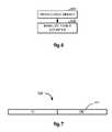
- FIG. 7illustrates the fields of an interrupt coalescing clock control (ICCC) register for the first DMA channel, utilizing aspects of the present invention.
- ICCCinterrupt coalescing clock control
- FIG. 1illustrates, as an example, a block diagram of a computer system 100 .
- a system memory 102is coupled to a CPU 101 through a memory controller 103 and a CPU bus 104 .
- a bus bridge 105bridges communications between the CPU bus 104 and a local bus 106 .
- An interrupt controller 107communicates interrupt requests to the CPU 101 from interrupt requesting components coupled to the local bus 106 .
- a direct memory access (DMA) controller 108manages DMA transfers between the system memory 102 and memory accessing components coupled to the local bus 106 .
- a bus arbiter 109arbitrates and grants requests to access the local bus 106 .
- DMAdirect memory access
- a number of interfacesare provided for communicating with devices that are external of the computer system 100 , such as external interfaces 110 - 1 to 110 -N which are coupled to the local bus 106 .
- external interfacesinclude a peripheral component interface (PCI) controller, one or more Ethernet interfaces, a serial peripheral interface (SPI), a general purpose input/output (GPIO) interface, an asynchronous transfer mode (ATM) interface, and a universal asynchronous receiver/transmitter (UART).
- PCIperipheral component interface
- SPIserial peripheral interface
- GPIOgeneral purpose input/output
- ATMasynchronous transfer mode
- UARTuniversal asynchronous receiver/transmitter
- a number of componentsare also provided for performing various functions in the computer system 100 , such as internal functions 112 - 1 to 112 -K which are coupled to the local bus 106 .
- One such internal functionis a DMA interrupt coalescer, which will be described in more detail below.
- Examples of other internal functionsinclude system integrity functions, counter timers, a security engine, and a random number generator.
- FIG. 2illustrates, as an example, a block diagram of a portion of the computer system 100 including the DMA controller 108 , the interrupt controller 107 , and a DMA interrupt coalescer 200 which functionally operates between the DMA controller 108 and the interrupt controller 107 .
- the DMA interrupt coalescer 200may also be integrated, in whole or in part, into the DMA controller 108 and/or the interrupt controller 107 .
- the DMA controller 108includes, for example, 32 independent DMA channels, all of which operate in substantially the same manner.
- Table Iillustrates DMA channel assignments for the DMA Controller 108 .
- Channels 0 - 4are assigned to servicing two Ethernet interfaces.
- Channels 5 - 6are assigned to servicing a FIFO holding memory 120 in the DMA controller 108 .
- Channel 7is assigned to servicing a PCI interface.
- Channels 8 - 9are assigned to service a security engine function.
- Channel 10is assigned to service a random number generator function.
- Channels 11 - 31are assigned to servicing various ATM communications with the system memory 102 .
- all DMA operationsare performed by reading DMA descriptors from the system memory 102 .
- a DMA is descriptoris read from memory to determine control information when a DMA descriptor operation begins, and is written back to memory with updated status information when a DMA descriptor operation completes.
- the DMA descriptorincludes a number of fields and bits such as a COUNT field indicating the number of bytes to transfer; a device command field (DEVCMD) for passing device specific control information to a peripheral at the start of a DMA descriptor operation, and record peripheral status information at the end of the DMA descriptor operation; and a device select (DS) field for indicating the peripheral device to be used during the DMA descriptor operation.
- a COUNT fieldindicating the number of bytes to transfer
- DEVCMDdevice command field
- DSdevice select
- a number of interrupt related bitssuch as a finished (F) bit indicating when set that DMA descriptor processing has ceased due to a finished event (e.g., the number of bytes specified in the COUNT field have been transferred); a done (D) bit indicating when set that DMA descriptor processing has ceased due to a done event (e.g., the device indicated in the DS field has indicated that it is done); an interrupt on done (IOD) bit indicating that a DONE interrupt is to be generated upon occurrence of a done event; and an interrupt on finished (IOF) bit indicating that a FINISHED interrupt is to be generated upon occurrence of a finished event.
- a finished (F) bitindicating when set that DMA descriptor processing has ceased due to a finished event (e.g., the number of bytes specified in the COUNT field have been transferred)
- a done (D) bitindicating when set that DMA descriptor processing has ceased due to a done event (e.g., the
- DMA descriptor chaining related bitssuch as a chain on done (COD) bit indicating when set that the DMA controller 108 is to load a next DMA descriptor in a linked list of DMA descriptors after processing for a current DMA descriptor ceases due to a done event, and a chain on finished (COF) bit indicating when set that the DMA controller 108 is to load a next DMA descriptor in a linked list of DMA descriptors after processing for a current DMA descriptor ceases due to a finished event.
- CODchain on done
- COFchain on finished
- DMA descriptorOther items included in the DMA descriptor are a terminated (T) bit indicating when set that DMA descriptor processing has been abnormally terminated; a current address (CA) field which is initialized with the DMA starting address at the start of a DMA operation and is updated when descriptor processing is completed; and a link (LINK) field pointing to a next DMA descriptor to be processed in a linked list of DMA descriptors.
- Tterminated
- CAcurrent address
- LINKlink
- the DMA interrupt coalescer 200includes, for example, 32 interrupt coalescing units individually servicing a corresponding channel of the DMA controller 108 .
- Each interrupt coalescing unitsuch as the one depicted in FIG. 3 for the first DMA channel, may receive a number of interrupts from its respective DMA channel, such as a FINISHED, DONE, CHAIN, or OTHER interrupt.
- the FINISH interruptindicates that the DMA controller 108 has finished its current processing task due to a finished event such as completion of a DMA transfer.
- the DONE interruptindicates that the DMA controller 108 has finished its current processing task due to a done event such as the device to from which a data transfer is being conducted generates a done indication.
- the CHAIN interruptindicates that a DMA descriptor chaining operation is taking place wherein a number of DMA descriptors are linked together through a linked list. Each of these interrupts is referred to as being a delayable interrupt, because immediate servicing of these interrupts is not required. Therefore, the interrupt coalescer 200 does not transmit an interrupt request to the interrupt controller 107 for any of these interrupts until a coalescing condition is satisfied.
- Examples of the OTHER interruptinclude an error interrupt which indicates that an error has occurred during the current DMA transfer, and a halt interrupt which indicates that the current DMA transfer has been halted for some reason. These interrupts are referred to as being non-delayable interrupts, because immediate servicing of these interrupts is required. Therefore, the interrupt coalescer 200 should transmit an interrupt request to the interrupt controller 107 for any of these interrupts without regard to any coalescing conditions.
- interrupts FINISHED, DONE, CHAIN and OTHERare provided on a single line or flag to their corresponding interrupt coalescing unit by OR'ing them together.
- the particular type of interrupt that caused activation of the line or setting of the flagcan then be determined by reading a status register (and a masking register if such a register is used) corresponding to the DMA channel in the DMA controller 108 .
- FIG. 3illustrates, as an example, a block diagram of an interrupt coalescing unit 300 of the DMA interrupt coalescer 200 .
- the interrupt coalescing unit 300is servicing the first DMA channel (DMA CH 0 ) of the DMA controller 108 .
- Other channels (DMA CH 1 ⁇ CH 31 ) of the DMA controller 108have similar interrupt coalescing units servicing them.
- Included in the interrupt coalescing unit 300are logic 301 , an interrupt coalescer control (ICC) register 304 , and an interrupt coalescing clock control (ICCC) register 305 .
- ICCinterrupt coalescer control
- ICCCinterrupt coalescing clock control
- the logic 301receives interrupts (e.g., FINISHED, DONE, CHAIN, and OTHER) from the DMA controller 108 , and transmits an interrupt request (INTRPT) to the interrupt controller 107 for its corresponding DMA channel (DMA CH 0 ) if either a coalescing condition is satisfied after receiving one or more delayable interrupts, or a non-delayable interrupt is received.
- interruptse.g., FINISHED, DONE, CHAIN, and OTHER
- coalescing conditionbeing satisfied is the condition that a non-zero period of time must transpire since a first of the one or more delayable interrupts was received.
- An interrupt in this caseis referred to as being “the first delayable interrupt” if it is the first delayable interrupt received since either system startup or the last transmission of an interrupt request by the logic 301 .
- Another example of a coalescing condition being satisfiedis the condition that a number of the one or more delayable interrupts received must exceed a programmed value.
- Designation of delayable interruptsis provided in the ICC register 304 as one-bit fields F, D and C, which respectively correspond to the FINISHED, DONE and CHAIN interrupts. These interrupts are coalesced by the logic 301 if their respective bit values are a “1”, and they are not coalesced (i.e., treated as non-delayable interrupts) if their respective bit values are a “0”. Interrupts that are not represented by one-bit fields in the ICC register 304 are treated as non-delayable interrupts, such as the OTHER interrupt shown in FIG. 3 .
- FIG. 4An example of the ICC register 304 is illustrated in FIG. 4
- FIG. 7An example of the ICCC register 305 is illustrated in FIG. 7 .
- Contents of both registersare programmable (i.e., write as well as read accessible) through the local bus 106 .
- the ICC register 304also includes a field for an event counter (ECNT) 302 and a timer counter (CCNT) 303 which are used for coalescing delayable interrupts.
- ECNTevent counter
- CCNTtimer counter
- FIG. 5illustrates a flow diagram of a method for coalescing interrupts for a DMA channel that is preferably performed by an interrupt coalescing unit such as the interrupt coalescing unit 300 illustrated in FIG. 3 .
- the methodis in an idle state and the event counter (ECNT) 302 in the ICC register 304 has been initialized to a count of zero at system startup or after a last transmission of an interrupt request for the DMA channel.
- ECNTevent counter
- an interruptis received, for example from the DMA controller 108 , and in 503 it is determined whether or not the interrupt is a delayable interrupt.
- the type of interrupte.g., FINISH, DONE, CHAIN or OTHER
- the interruptis determined to be a non-delayable interrupt in 503 , and the method proceeds to 511 so that the interrupt request will be transmitted without a coalescing delay.
- the ICC register 304Since the ICC register 304 has one-bit fields defined for a FINISH (F field), DONE (D field), and CHAIN (C field), these interrupts will be considered delayable interrupts for the purposes of 503 , and if any one of these types of interrupts is received, then the method proceeds to 504 . On the other hand, since the ICC register 304 does not have an one-bit field defined for an OTHER interrupt, these interrupts will be considered non-delayable interrupts for the purposes of 503 , and if any one of these types of interrupts is received, then the method proceeds to 511 .
- the value of the one-bit field corresponding to a received delayable interrupt in 502is read from the ICC register 304 .
- the bitis set (i.e., it has been programmed to have a value of “1”), then the delayable interrupt is to be coalesced and the method proceeds with 506 .
- the bitis not set (i.e., it's value is “0”), then the delayable interrupt is not be coalesced and the method proceeds to 511 to transmit an interrupt request to the interrupt controller 107 without a coalescing delay.
- the event counter (ECNT) 302is incremented by one to indicate receipt of a delayable interrupt.
- the count in the event counter (ECNT) 302 of the ICC register 304is compared with a programmed value (ECMP) which is also provided in the ICC register 304 . If the count of the event counter (ECNT) 302 equals the programmed value (ECMP), then the method proceeds to 511 to transmit an interrupt request to the interrupt controller 107 . On the other hand, if the count of the event counter 302 is less than the programmed value (ECMP), then the method proceeds to 508 .
- the methoddetermines whether or not the timer counter (CCNT) 303 in the ICC register 304 has been started. The preferred way to do this is to check the count of the event counter (ECNT) 302 in the ICC register 304 . If the count is one, then the timer counter (CCNT) 303 should be started and the method proceeds to 509 . On the other hand, if the count (ECNT) is greater than one, then the timer counter (CCNT) 303 is assumed to have already been started, and the method proceeds back to 501 to wait for either the receipt of another interrupt in 502 or the saturation of the timer counter (CCNT) 303 in 510 .
- FIG. 6illustrates, as an example, a flow diagram of a method for initializing the timer counter (CCNT) 303 in the DMA interrupt coalescer 200 .
- the logic 301reads a coalescing clock select (CCLK) field of the ICC register 304 , which indicates the clock source to be used for incrementing the timer counter (CCNT) 303 .
- CCLKcoalescing clock select
- each of the coalescing clock sourceshas a corresponding register such as the ICCC register 305 illustrated in FIG. 7 .
- the coalescing clock sourceis then generated by dividing the clock 306 of the local bus 106 by the value indicated in the clock divisor (DIV) field 307 in the ICCC register 305 .
- the logic 301initializes the timer counter (CCNT) 303 by setting its value to zero in the ICC register 304 , so that it is effectively reset upon the logic 301 receiving a first delayable interrupt since its last transmission of an interrupt request to the interrupt controller 107 or system startup.
- the timer counter 303is then incremented with each rising edge of the coalescer clock source until it saturates at its maximum value of 0x1F.
- the decision block 510results in a YES determination, and the method proceeds to 511 .
- an interrupt request(INTRPT) is transmitted by the logic 301 to the interrupt controller 107 for the DMA channel.
- the type of interrupt(s) causing the interrupt request(INTRPT) may be ascertained by the interrupt controller 107 or the CPU 101 by reading a status register corresponding to the DMA channel in the DMA controller 108 .
- the event counter (ECNT) 302is reset to a count of zero.
- the timer counter (CCNT) 303may also be reset at this time with its coalescing clock source disconnected so as not to increment its count until the timer counter (CCNT) 303 is restarted in 509 .
- 501 ⁇ 511describes a method in which the interrupt coalescer 200 transmits an interrupt request (INTRPT) for a DMA channel to the interrupt controller 107 after a coalescing condition is satisfied after receiving one or more delayable interrupts, and/or transmits the interrupt request to the interrupt controller 107 without a coalescing delay if after receiving a non-delayable interrupt.
- interrupt requestan interrupt request
- the interrupt coalescer 200transmits an interrupt request (INTRPT) for a DMA channel to the interrupt controller 107 after a coalescing condition is satisfied after receiving one or more delayable interrupts, and/or transmits the interrupt request to the interrupt controller 107 without a coalescing delay if after receiving a non-delayable interrupt.
Landscapes
- Engineering & Computer Science (AREA)
- Theoretical Computer Science (AREA)
- Physics & Mathematics (AREA)
- General Engineering & Computer Science (AREA)
- General Physics & Mathematics (AREA)
- Bus Control (AREA)
Abstract
Description
| TABLE I | |||
| DMA Channel | Device Description | ||
| Channel 0 | Ethernet 0 | ||
| Channel | |||
| 1 | Ethernet 0 | ||
| Channel | |||
| 2 | Ethernet 1 Receive | ||
| Channel 3 | Ethernet 1 Transmit | ||
| Channel 4 | Memory to Memory (Memory to Holding FIFO) | ||
| Channel 5 | Memory to Memory (Holding FIFO to Memory) | ||
| Channel 6 | PCI (PCI to Memory) | ||
| Channel 7 | PCI (Memory to PCI) | ||
| Channel 8 | Security Engine Input | ||
| Channel 9 | Security Engine Output | ||
| Channel 10 | Random Number Generator | ||
| Channels 11-31 | ATM | ||
Claims (14)
Priority Applications (1)
| Application Number | Priority Date | Filing Date | Title |
|---|---|---|---|
| US10/939,536US7478186B1 (en) | 2004-06-03 | 2004-09-13 | Interrupt coalescer for DMA channel |
Applications Claiming Priority (2)
| Application Number | Priority Date | Filing Date | Title |
|---|---|---|---|
| US57688104P | 2004-06-03 | 2004-06-03 | |
| US10/939,536US7478186B1 (en) | 2004-06-03 | 2004-09-13 | Interrupt coalescer for DMA channel |
Publications (1)
| Publication Number | Publication Date |
|---|---|
| US7478186B1true US7478186B1 (en) | 2009-01-13 |
Family
ID=40223973
Family Applications (1)
| Application Number | Title | Priority Date | Filing Date |
|---|---|---|---|
| US10/939,536Expired - Fee RelatedUS7478186B1 (en) | 2004-06-03 | 2004-09-13 | Interrupt coalescer for DMA channel |
Country Status (1)
| Country | Link |
|---|---|
| US (1) | US7478186B1 (en) |
Cited By (67)
| Publication number | Priority date | Publication date | Assignee | Title |
|---|---|---|---|---|
| US20080077724A1 (en)* | 2006-09-22 | 2008-03-27 | Parthasarathy Sarangam | Interrupt coalescing control scheme |
| US20080147946A1 (en)* | 2006-12-15 | 2008-06-19 | Microchip Technology Incorporated | Interrupt Controller |
| US20080215787A1 (en)* | 2007-02-06 | 2008-09-04 | Shay Mizrachi | Method and System for Processing Status Blocks Based on Interrupt Mapping |
| US20100306433A1 (en)* | 2009-05-26 | 2010-12-02 | Fujitsu Semiconductor Limited | Interrupt-notification control unit, semiconductor integrated circuit and methods therefor |
| US20110093637A1 (en)* | 2009-10-16 | 2011-04-21 | Brocade Communications Systems, Inc. | Interrupt Moderation |
| US8103809B1 (en) | 2009-01-16 | 2012-01-24 | F5 Networks, Inc. | Network devices with multiple direct memory access channels and methods thereof |
| US8112491B1 (en) | 2009-01-16 | 2012-02-07 | F5 Networks, Inc. | Methods and systems for providing direct DMA |
| US20120054513A1 (en)* | 2010-08-30 | 2012-03-01 | Ming-Chi Chen | Apparatus for performing timer management regarding a system timer scheduler service, and associated method |
| US20120210104A1 (en)* | 2011-02-14 | 2012-08-16 | Qnx Software Systems Gmbh & Co. Kg | Suspendable interrupts for processor idle management |
| EP2490100A1 (en)* | 2011-02-14 | 2012-08-22 | QNX Software Systems Co. | Suspendable interrupts for processor idle management |
| US8306036B1 (en) | 2008-06-20 | 2012-11-06 | F5 Networks, Inc. | Methods and systems for hierarchical resource allocation through bookmark allocation |
| US8447884B1 (en) | 2008-12-01 | 2013-05-21 | F5 Networks, Inc. | Methods for mapping virtual addresses to physical addresses in a network device and systems thereof |
| US8537825B1 (en) | 2007-09-28 | 2013-09-17 | F5 Networks, Inc. | Lockless atomic table update |
| US20130297832A1 (en)* | 2009-04-24 | 2013-11-07 | Vmware, Inc. | Interrupt coalescing for outstanding input/output completions |
| US8769681B1 (en) | 2008-08-11 | 2014-07-01 | F5 Networks, Inc. | Methods and system for DMA based distributed denial of service protection |
| US20140195708A1 (en)* | 2013-01-04 | 2014-07-10 | International Business Machines Corporation | Determining when to throttle interrupts to limit interrupt processing to an interrupt processing time period |
| US8880696B1 (en) | 2009-01-16 | 2014-11-04 | F5 Networks, Inc. | Methods for sharing bandwidth across a packetized bus and systems thereof |
| US8880632B1 (en) | 2009-01-16 | 2014-11-04 | F5 Networks, Inc. | Method and apparatus for performing multiple DMA channel based network quality of service |
| WO2014204501A1 (en)* | 2013-06-19 | 2014-12-24 | Microsoft Corporation | Selective blocking of background activity |
| US20150134867A1 (en)* | 2012-07-17 | 2015-05-14 | Siemens Aktiengesellschaft | Device and method for interrupt coalescing |
| US9036822B1 (en) | 2012-02-15 | 2015-05-19 | F5 Networks, Inc. | Methods for managing user information and devices thereof |
| WO2015143594A1 (en)* | 2014-03-24 | 2015-10-01 | Intel Corporation | Syncronization of interrupt processing to reduce power consumption |
| US9152483B2 (en) | 2009-01-16 | 2015-10-06 | F5 Networks, Inc. | Network devices with multiple fully isolated and independently resettable direct memory access channels and methods thereof |
| US9270602B1 (en) | 2012-12-31 | 2016-02-23 | F5 Networks, Inc. | Transmit rate pacing of large network traffic bursts to reduce jitter, buffer overrun, wasted bandwidth, and retransmissions |
| US9313047B2 (en) | 2009-11-06 | 2016-04-12 | F5 Networks, Inc. | Handling high throughput and low latency network data packets in a traffic management device |
| EP2672386A3 (en)* | 2012-06-08 | 2016-07-20 | Samsung Electronics Co., Ltd | Apparatus and method for processing asynchronous event information |
| US9465681B2 (en)* | 2014-03-14 | 2016-10-11 | International Business Machines Corporation | Coalescing stages in a multiple stage completion sequence |
| US9628388B2 (en) | 2014-03-14 | 2017-04-18 | International Business Machines Corporation | Remotely controlled message queue |
| US9635024B2 (en) | 2013-12-16 | 2017-04-25 | F5 Networks, Inc. | Methods for facilitating improved user authentication using persistent data and devices thereof |
| US9727494B1 (en)* | 2012-10-11 | 2017-08-08 | Qlogic, Corporation | Method and system for communication between a computing device and a peripheral device |
| US9864606B2 (en) | 2013-09-05 | 2018-01-09 | F5 Networks, Inc. | Methods for configurable hardware logic device reloading and devices thereof |
| US9875205B1 (en) | 2013-03-15 | 2018-01-23 | Bitmicro Networks, Inc. | Network of memory systems |
| US9934160B1 (en) | 2013-03-15 | 2018-04-03 | Bitmicro Llc | Bit-mapped DMA and IOC transfer with dependency table comprising plurality of index fields in the cache for DMA transfer |
| US9934045B1 (en) | 2013-03-15 | 2018-04-03 | Bitmicro Networks, Inc. | Embedded system boot from a storage device |
| US9952991B1 (en) | 2014-04-17 | 2018-04-24 | Bitmicro Networks, Inc. | Systematic method on queuing of descriptors for multiple flash intelligent DMA engine operation |
| US9977077B1 (en) | 2013-03-14 | 2018-05-22 | Bitmicro Llc | Self-test solution for delay locked loops |
| US9996419B1 (en) | 2012-05-18 | 2018-06-12 | Bitmicro Llc | Storage system with distributed ECC capability |
| US10015143B1 (en) | 2014-06-05 | 2018-07-03 | F5 Networks, Inc. | Methods for securing one or more license entitlement grants and devices thereof |
| US10013373B1 (en) | 2013-03-15 | 2018-07-03 | Bitmicro Networks, Inc. | Multi-level message passing descriptor |
| US10025736B1 (en) | 2014-04-17 | 2018-07-17 | Bitmicro Networks, Inc. | Exchange message protocol message transmission between two devices |
| US10033837B1 (en) | 2012-09-29 | 2018-07-24 | F5 Networks, Inc. | System and method for utilizing a data reducing module for dictionary compression of encoded data |
| US10042792B1 (en) | 2014-04-17 | 2018-08-07 | Bitmicro Networks, Inc. | Method for transferring and receiving frames across PCI express bus for SSD device |
| US10042799B1 (en) | 2013-03-15 | 2018-08-07 | Bitmicro, Llc | Bit-mapped DMA transfer with dependency table configured to monitor status so that a processor is not rendered as a bottleneck in a system |
| US10055150B1 (en) | 2014-04-17 | 2018-08-21 | Bitmicro Networks, Inc. | Writing volatile scattered memory metadata to flash device |
| US10078604B1 (en)* | 2014-04-17 | 2018-09-18 | Bitmicro Networks, Inc. | Interrupt coalescing |
| US10082966B1 (en) | 2009-09-14 | 2018-09-25 | Bitmicro Llc | Electronic storage device |
| US10102162B2 (en)* | 2015-05-27 | 2018-10-16 | Samsung Electronics Co., Ltd. | Method and apparatus for processing adaptive interrupt, host employing the same, I/O device and system |
| US10120586B1 (en) | 2007-11-16 | 2018-11-06 | Bitmicro, Llc | Memory transaction with reduced latency |
| US10133686B2 (en) | 2009-09-07 | 2018-11-20 | Bitmicro Llc | Multilevel memory bus system |
| US10135831B2 (en) | 2011-01-28 | 2018-11-20 | F5 Networks, Inc. | System and method for combining an access control system with a traffic management system |
| US10149399B1 (en) | 2009-09-04 | 2018-12-04 | Bitmicro Llc | Solid state drive with improved enclosure assembly |
| CN109062834A (en)* | 2018-06-19 | 2018-12-21 | 广州星雨光电设备有限公司 | The SPI means of communication based on DMA, electronic equipment, storage medium, device |
| US10182013B1 (en) | 2014-12-01 | 2019-01-15 | F5 Networks, Inc. | Methods for managing progressive image delivery and devices thereof |
| US10180887B1 (en) | 2011-10-05 | 2019-01-15 | Bitmicro Llc | Adaptive power cycle sequences for data recovery |
| US10210084B1 (en) | 2013-03-15 | 2019-02-19 | Bitmicro Llc | Multi-leveled cache management in a hybrid storage system |
| US10375155B1 (en) | 2013-02-19 | 2019-08-06 | F5 Networks, Inc. | System and method for achieving hardware acceleration for asymmetric flow connections |
| US10423554B1 (en) | 2013-03-15 | 2019-09-24 | Bitmicro Networks, Inc | Bus arbitration with routing and failover mechanism |
| US10489319B2 (en)* | 2016-12-20 | 2019-11-26 | Atmel Corporation | Automatic transmission of dummy bits in bus master |
| US10489318B1 (en) | 2013-03-15 | 2019-11-26 | Bitmicro Networks, Inc. | Scatter-gather approach for parallel data transfer in a mass storage system |
| US10552050B1 (en) | 2017-04-07 | 2020-02-04 | Bitmicro Llc | Multi-dimensional computer storage system |
| CN111078619A (en)* | 2019-03-29 | 2020-04-28 | 新华三技术有限公司 | A conversion device, network equipment and data transmission method |
| US10972453B1 (en) | 2017-05-03 | 2021-04-06 | F5 Networks, Inc. | Methods for token refreshment based on single sign-on (SSO) for federated identity environments and devices thereof |
| US20220350762A1 (en)* | 2021-04-30 | 2022-11-03 | SK Hynix Inc. | Apparatus and method for data communications between non-volatile memory devices and a memory controller |
| US11537716B1 (en) | 2018-11-13 | 2022-12-27 | F5, Inc. | Methods for detecting changes to a firmware and devices thereof |
| US11838851B1 (en) | 2014-07-15 | 2023-12-05 | F5, Inc. | Methods for managing L7 traffic classification and devices thereof |
| US11855898B1 (en) | 2018-03-14 | 2023-12-26 | F5, Inc. | Methods for traffic dependent direct memory access optimization and devices thereof |
| US11895138B1 (en) | 2015-02-02 | 2024-02-06 | F5, Inc. | Methods for improving web scanner accuracy and devices thereof |
Citations (17)
| Publication number | Priority date | Publication date | Assignee | Title |
|---|---|---|---|---|
| US5363506A (en)* | 1990-07-17 | 1994-11-08 | Kabushiki Kaisha Toshiba | Information processor with delayed interrupt device |
| US5708814A (en)* | 1995-11-21 | 1998-01-13 | Microsoft Corporation | Method and apparatus for reducing the rate of interrupts by generating a single interrupt for a group of events |
| US5708817A (en)* | 1995-05-31 | 1998-01-13 | Apple Computer, Inc. | Programmable delay of an interrupt |
| US5797037A (en)* | 1995-03-31 | 1998-08-18 | Cirrus Logic, Inc. | Interrupt request control logic reducing the number of interrupts required for I/O data transfer |
| US5828856A (en)* | 1994-01-28 | 1998-10-27 | Apple Computer, Inc. | Dual bus concurrent multi-channel direct memory access controller and method |
| US5943479A (en)* | 1997-01-02 | 1999-08-24 | Digital Equipment Corporation | Method for reducing the rate of interrupts in a high speed I/O controller |
| US6065089A (en) | 1998-06-25 | 2000-05-16 | Lsi Logic Corporation | Method and apparatus for coalescing I/O interrupts that efficiently balances performance and latency |
| US6115776A (en)* | 1996-12-05 | 2000-09-05 | 3Com Corporation | Network and adaptor with time-based and packet number based interrupt combinations |
| US6189066B1 (en) | 1999-01-26 | 2001-02-13 | 3Com Corporation | System and method for dynamically selecting interrupt time interval threshold parameters |
| US6192440B1 (en)* | 1999-01-26 | 2001-02-20 | 3Com Corporation | System and method for dynamically selecting interrupt storage time threshold parameters |
| US6615305B1 (en)* | 1998-08-27 | 2003-09-02 | Intel Corporation | Interrupt pacing in data transfer unit |
| US6658502B1 (en)* | 2000-06-13 | 2003-12-02 | Koninklijke Philips Electronics N.V. | Multi-channel and multi-modal direct memory access controller for optimizing performance of host bus |
| US6760799B1 (en)* | 1999-09-30 | 2004-07-06 | Intel Corporation | Reduced networking interrupts |
| US6766400B2 (en)* | 2000-07-10 | 2004-07-20 | Nec Corporation | Disk array apparatus and interrupt execution method of the same |
| US6988156B2 (en)* | 2002-04-18 | 2006-01-17 | Sun Microsystems, Inc. | System and method for dynamically tuning interrupt coalescing parameters |
| US7032049B2 (en)* | 2000-09-22 | 2006-04-18 | Infineon Technologies Ag | Apparatus for relaying received interrupt requests |
| US7054972B2 (en)* | 2002-12-13 | 2006-05-30 | Lsi Logic Corporation | Apparatus and method for dynamically enabling and disabling interrupt coalescing in data processing system |
- 2004
- 2004-09-13USUS10/939,536patent/US7478186B1/ennot_activeExpired - Fee Related
Patent Citations (17)
| Publication number | Priority date | Publication date | Assignee | Title |
|---|---|---|---|---|
| US5363506A (en)* | 1990-07-17 | 1994-11-08 | Kabushiki Kaisha Toshiba | Information processor with delayed interrupt device |
| US5828856A (en)* | 1994-01-28 | 1998-10-27 | Apple Computer, Inc. | Dual bus concurrent multi-channel direct memory access controller and method |
| US5797037A (en)* | 1995-03-31 | 1998-08-18 | Cirrus Logic, Inc. | Interrupt request control logic reducing the number of interrupts required for I/O data transfer |
| US5708817A (en)* | 1995-05-31 | 1998-01-13 | Apple Computer, Inc. | Programmable delay of an interrupt |
| US5708814A (en)* | 1995-11-21 | 1998-01-13 | Microsoft Corporation | Method and apparatus for reducing the rate of interrupts by generating a single interrupt for a group of events |
| US6115776A (en)* | 1996-12-05 | 2000-09-05 | 3Com Corporation | Network and adaptor with time-based and packet number based interrupt combinations |
| US5943479A (en)* | 1997-01-02 | 1999-08-24 | Digital Equipment Corporation | Method for reducing the rate of interrupts in a high speed I/O controller |
| US6065089A (en) | 1998-06-25 | 2000-05-16 | Lsi Logic Corporation | Method and apparatus for coalescing I/O interrupts that efficiently balances performance and latency |
| US6615305B1 (en)* | 1998-08-27 | 2003-09-02 | Intel Corporation | Interrupt pacing in data transfer unit |
| US6189066B1 (en) | 1999-01-26 | 2001-02-13 | 3Com Corporation | System and method for dynamically selecting interrupt time interval threshold parameters |
| US6192440B1 (en)* | 1999-01-26 | 2001-02-20 | 3Com Corporation | System and method for dynamically selecting interrupt storage time threshold parameters |
| US6760799B1 (en)* | 1999-09-30 | 2004-07-06 | Intel Corporation | Reduced networking interrupts |
| US6658502B1 (en)* | 2000-06-13 | 2003-12-02 | Koninklijke Philips Electronics N.V. | Multi-channel and multi-modal direct memory access controller for optimizing performance of host bus |
| US6766400B2 (en)* | 2000-07-10 | 2004-07-20 | Nec Corporation | Disk array apparatus and interrupt execution method of the same |
| US7032049B2 (en)* | 2000-09-22 | 2006-04-18 | Infineon Technologies Ag | Apparatus for relaying received interrupt requests |
| US6988156B2 (en)* | 2002-04-18 | 2006-01-17 | Sun Microsystems, Inc. | System and method for dynamically tuning interrupt coalescing parameters |
| US7054972B2 (en)* | 2002-12-13 | 2006-05-30 | Lsi Logic Corporation | Apparatus and method for dynamically enabling and disabling interrupt coalescing in data processing system |
Non-Patent Citations (4)
| Title |
|---|
| Definition of Direct Memory Access from Wikipedia.* |
| DMA Fundamentals on Various PC Platforms, Harvey et al., National Instruments Corporation, Apr. 1991.* |
| EP660 DMA Controller, Eureka Technology Inc., 2000.* |
| Introduction to Counter/Timer Hardware, Michael Barr's Embedded Systems Glossary, 2002.* |
Cited By (96)
| Publication number | Priority date | Publication date | Assignee | Title |
|---|---|---|---|---|
| US20080077724A1 (en)* | 2006-09-22 | 2008-03-27 | Parthasarathy Sarangam | Interrupt coalescing control scheme |
| US7987307B2 (en)* | 2006-09-22 | 2011-07-26 | Intel Corporation | Interrupt coalescing control scheme |
| US20080147946A1 (en)* | 2006-12-15 | 2008-06-19 | Microchip Technology Incorporated | Interrupt Controller |
| US7788434B2 (en)* | 2006-12-15 | 2010-08-31 | Microchip Technology Incorporated | Interrupt controller handling interrupts with and without coalescing |
| US7949813B2 (en)* | 2007-02-06 | 2011-05-24 | Broadcom Corporation | Method and system for processing status blocks in a CPU based on index values and interrupt mapping |
| US20080215787A1 (en)* | 2007-02-06 | 2008-09-04 | Shay Mizrachi | Method and System for Processing Status Blocks Based on Interrupt Mapping |
| US8537825B1 (en) | 2007-09-28 | 2013-09-17 | F5 Networks, Inc. | Lockless atomic table update |
| US10120586B1 (en) | 2007-11-16 | 2018-11-06 | Bitmicro, Llc | Memory transaction with reduced latency |
| US8306036B1 (en) | 2008-06-20 | 2012-11-06 | F5 Networks, Inc. | Methods and systems for hierarchical resource allocation through bookmark allocation |
| US8769681B1 (en) | 2008-08-11 | 2014-07-01 | F5 Networks, Inc. | Methods and system for DMA based distributed denial of service protection |
| US8447884B1 (en) | 2008-12-01 | 2013-05-21 | F5 Networks, Inc. | Methods for mapping virtual addresses to physical addresses in a network device and systems thereof |
| US9152483B2 (en) | 2009-01-16 | 2015-10-06 | F5 Networks, Inc. | Network devices with multiple fully isolated and independently resettable direct memory access channels and methods thereof |
| US9606946B2 (en) | 2009-01-16 | 2017-03-28 | F5 Networks, Inc. | Methods for sharing bandwidth across a packetized bus and systems thereof |
| US8112491B1 (en) | 2009-01-16 | 2012-02-07 | F5 Networks, Inc. | Methods and systems for providing direct DMA |
| US9154453B2 (en) | 2009-01-16 | 2015-10-06 | F5 Networks, Inc. | Methods and systems for providing direct DMA |
| US8880696B1 (en) | 2009-01-16 | 2014-11-04 | F5 Networks, Inc. | Methods for sharing bandwidth across a packetized bus and systems thereof |
| US8984178B2 (en) | 2009-01-16 | 2015-03-17 | F5 Networks, Inc. | Network devices with multiple direct memory access channels and methods thereof |
| US8880632B1 (en) | 2009-01-16 | 2014-11-04 | F5 Networks, Inc. | Method and apparatus for performing multiple DMA channel based network quality of service |
| US8103809B1 (en) | 2009-01-16 | 2012-01-24 | F5 Networks, Inc. | Network devices with multiple direct memory access channels and methods thereof |
| US9336165B2 (en)* | 2009-04-24 | 2016-05-10 | Vmware, Inc. | Interrupt coalescing for outstanding input/output completions |
| US20130297832A1 (en)* | 2009-04-24 | 2013-11-07 | Vmware, Inc. | Interrupt coalescing for outstanding input/output completions |
| US20100306433A1 (en)* | 2009-05-26 | 2010-12-02 | Fujitsu Semiconductor Limited | Interrupt-notification control unit, semiconductor integrated circuit and methods therefor |
| US8612661B2 (en)* | 2009-05-26 | 2013-12-17 | Fujitsu Semiconductor Limited | Interrupt-notification control unit, semiconductor integrated circuit and methods therefor |
| US10149399B1 (en) | 2009-09-04 | 2018-12-04 | Bitmicro Llc | Solid state drive with improved enclosure assembly |
| US10133686B2 (en) | 2009-09-07 | 2018-11-20 | Bitmicro Llc | Multilevel memory bus system |
| US10082966B1 (en) | 2009-09-14 | 2018-09-25 | Bitmicro Llc | Electronic storage device |
| US8244946B2 (en)* | 2009-10-16 | 2012-08-14 | Brocade Communications Systems, Inc. | Interrupt moderation |
| US8677042B2 (en) | 2009-10-16 | 2014-03-18 | Brocade Communications Systems, Inc. | Interrupt moderation |
| US8397007B2 (en) | 2009-10-16 | 2013-03-12 | Brocade Communications Systems, Inc. | Interrupt moderation |
| US20110093637A1 (en)* | 2009-10-16 | 2011-04-21 | Brocade Communications Systems, Inc. | Interrupt Moderation |
| US9313047B2 (en) | 2009-11-06 | 2016-04-12 | F5 Networks, Inc. | Handling high throughput and low latency network data packets in a traffic management device |
| US8713348B2 (en)* | 2010-08-30 | 2014-04-29 | Mediatek Inc. | Apparatus for performing timer management regarding a system timer scheduler service, and associated method |
| US20120054513A1 (en)* | 2010-08-30 | 2012-03-01 | Ming-Chi Chen | Apparatus for performing timer management regarding a system timer scheduler service, and associated method |
| US10135831B2 (en) | 2011-01-28 | 2018-11-20 | F5 Networks, Inc. | System and method for combining an access control system with a traffic management system |
| US20120210104A1 (en)* | 2011-02-14 | 2012-08-16 | Qnx Software Systems Gmbh & Co. Kg | Suspendable interrupts for processor idle management |
| US8504753B2 (en)* | 2011-02-14 | 2013-08-06 | Qnx Software Systems Limited | Suspendable interrupts for processor idle management |
| EP2490100A1 (en)* | 2011-02-14 | 2012-08-22 | QNX Software Systems Co. | Suspendable interrupts for processor idle management |
| US10180887B1 (en) | 2011-10-05 | 2019-01-15 | Bitmicro Llc | Adaptive power cycle sequences for data recovery |
| US9036822B1 (en) | 2012-02-15 | 2015-05-19 | F5 Networks, Inc. | Methods for managing user information and devices thereof |
| US9996419B1 (en) | 2012-05-18 | 2018-06-12 | Bitmicro Llc | Storage system with distributed ECC capability |
| EP2672386A3 (en)* | 2012-06-08 | 2016-07-20 | Samsung Electronics Co., Ltd | Apparatus and method for processing asynchronous event information |
| US20150134867A1 (en)* | 2012-07-17 | 2015-05-14 | Siemens Aktiengesellschaft | Device and method for interrupt coalescing |
| US10033837B1 (en) | 2012-09-29 | 2018-07-24 | F5 Networks, Inc. | System and method for utilizing a data reducing module for dictionary compression of encoded data |
| US9727494B1 (en)* | 2012-10-11 | 2017-08-08 | Qlogic, Corporation | Method and system for communication between a computing device and a peripheral device |
| US9270602B1 (en) | 2012-12-31 | 2016-02-23 | F5 Networks, Inc. | Transmit rate pacing of large network traffic bursts to reduce jitter, buffer overrun, wasted bandwidth, and retransmissions |
| US9946670B2 (en) | 2013-01-04 | 2018-04-17 | International Business Machines Corporation | Determining when to throttle interrupts to limit interrupt processing to an interrupt processing time period |
| US9164935B2 (en)* | 2013-01-04 | 2015-10-20 | International Business Machines Corporation | Determining when to throttle interrupts to limit interrupt processing to an interrupt processing time period |
| US20140195708A1 (en)* | 2013-01-04 | 2014-07-10 | International Business Machines Corporation | Determining when to throttle interrupts to limit interrupt processing to an interrupt processing time period |
| US10375155B1 (en) | 2013-02-19 | 2019-08-06 | F5 Networks, Inc. | System and method for achieving hardware acceleration for asymmetric flow connections |
| US9977077B1 (en) | 2013-03-14 | 2018-05-22 | Bitmicro Llc | Self-test solution for delay locked loops |
| US10042799B1 (en) | 2013-03-15 | 2018-08-07 | Bitmicro, Llc | Bit-mapped DMA transfer with dependency table configured to monitor status so that a processor is not rendered as a bottleneck in a system |
| US10210084B1 (en) | 2013-03-15 | 2019-02-19 | Bitmicro Llc | Multi-leveled cache management in a hybrid storage system |
| US10489318B1 (en) | 2013-03-15 | 2019-11-26 | Bitmicro Networks, Inc. | Scatter-gather approach for parallel data transfer in a mass storage system |
| US9875205B1 (en) | 2013-03-15 | 2018-01-23 | Bitmicro Networks, Inc. | Network of memory systems |
| US10423554B1 (en) | 2013-03-15 | 2019-09-24 | Bitmicro Networks, Inc | Bus arbitration with routing and failover mechanism |
| US9934160B1 (en) | 2013-03-15 | 2018-04-03 | Bitmicro Llc | Bit-mapped DMA and IOC transfer with dependency table comprising plurality of index fields in the cache for DMA transfer |
| US9934045B1 (en) | 2013-03-15 | 2018-04-03 | Bitmicro Networks, Inc. | Embedded system boot from a storage device |
| US10013373B1 (en) | 2013-03-15 | 2018-07-03 | Bitmicro Networks, Inc. | Multi-level message passing descriptor |
| CN105378588A (en)* | 2013-06-19 | 2016-03-02 | 微软技术许可有限责任公司 | Selective blocking of background activity |
| US9292080B2 (en) | 2013-06-19 | 2016-03-22 | Microsoft Technology Licensing, Llc | Selective blocking of background activity |
| WO2014204501A1 (en)* | 2013-06-19 | 2014-12-24 | Microsoft Corporation | Selective blocking of background activity |
| US10088892B2 (en) | 2013-06-19 | 2018-10-02 | Microsoft Technology Licensing, Llc | Selective blocking of background activity |
| CN105378588B (en)* | 2013-06-19 | 2019-04-26 | 微软技术许可有限责任公司 | Selective blocking of background activities |
| US9864606B2 (en) | 2013-09-05 | 2018-01-09 | F5 Networks, Inc. | Methods for configurable hardware logic device reloading and devices thereof |
| US9635024B2 (en) | 2013-12-16 | 2017-04-25 | F5 Networks, Inc. | Methods for facilitating improved user authentication using persistent data and devices thereof |
| US9465681B2 (en)* | 2014-03-14 | 2016-10-11 | International Business Machines Corporation | Coalescing stages in a multiple stage completion sequence |
| US20180006947A1 (en)* | 2014-03-14 | 2018-01-04 | International Business Machines Corporation | Remotely controlled message queue |
| US10616115B2 (en) | 2014-03-14 | 2020-04-07 | International Business Machines Corporation | Remotely controlled message queue |
| US9542243B2 (en) | 2014-03-14 | 2017-01-10 | International Business Machines Corporation | Coalescing stages in a multiple stage completion sequence |
| US9628388B2 (en) | 2014-03-14 | 2017-04-18 | International Business Machines Corporation | Remotely controlled message queue |
| US9923824B2 (en)* | 2014-03-14 | 2018-03-20 | International Business Machines Corporation | Remotely controlled message queue |
| US9843518B2 (en) | 2014-03-14 | 2017-12-12 | International Business Machines Corporation | Remotely controlled message queue |
| EP4086776A1 (en)* | 2014-03-24 | 2022-11-09 | INTEL Corporation | Syncronization of interrupt processing to reduce power consumption |
| US10089263B2 (en) | 2014-03-24 | 2018-10-02 | Intel Corporation | Synchronization of interrupt processing to reduce power consumption |
| WO2015143594A1 (en)* | 2014-03-24 | 2015-10-01 | Intel Corporation | Syncronization of interrupt processing to reduce power consumption |
| EP3123343A4 (en)* | 2014-03-24 | 2017-11-22 | Intel Corporation | Synchronization of interrupt processing to reduce power consumption |
| US9952991B1 (en) | 2014-04-17 | 2018-04-24 | Bitmicro Networks, Inc. | Systematic method on queuing of descriptors for multiple flash intelligent DMA engine operation |
| US10042792B1 (en) | 2014-04-17 | 2018-08-07 | Bitmicro Networks, Inc. | Method for transferring and receiving frames across PCI express bus for SSD device |
| US10055150B1 (en) | 2014-04-17 | 2018-08-21 | Bitmicro Networks, Inc. | Writing volatile scattered memory metadata to flash device |
| US10078604B1 (en)* | 2014-04-17 | 2018-09-18 | Bitmicro Networks, Inc. | Interrupt coalescing |
| US10025736B1 (en) | 2014-04-17 | 2018-07-17 | Bitmicro Networks, Inc. | Exchange message protocol message transmission between two devices |
| US10015143B1 (en) | 2014-06-05 | 2018-07-03 | F5 Networks, Inc. | Methods for securing one or more license entitlement grants and devices thereof |
| US11838851B1 (en) | 2014-07-15 | 2023-12-05 | F5, Inc. | Methods for managing L7 traffic classification and devices thereof |
| US10182013B1 (en) | 2014-12-01 | 2019-01-15 | F5 Networks, Inc. | Methods for managing progressive image delivery and devices thereof |
| US11895138B1 (en) | 2015-02-02 | 2024-02-06 | F5, Inc. | Methods for improving web scanner accuracy and devices thereof |
| US10102162B2 (en)* | 2015-05-27 | 2018-10-16 | Samsung Electronics Co., Ltd. | Method and apparatus for processing adaptive interrupt, host employing the same, I/O device and system |
| US10489319B2 (en)* | 2016-12-20 | 2019-11-26 | Atmel Corporation | Automatic transmission of dummy bits in bus master |
| US10552050B1 (en) | 2017-04-07 | 2020-02-04 | Bitmicro Llc | Multi-dimensional computer storage system |
| US10972453B1 (en) | 2017-05-03 | 2021-04-06 | F5 Networks, Inc. | Methods for token refreshment based on single sign-on (SSO) for federated identity environments and devices thereof |
| US11855898B1 (en) | 2018-03-14 | 2023-12-26 | F5, Inc. | Methods for traffic dependent direct memory access optimization and devices thereof |
| CN109062834A (en)* | 2018-06-19 | 2018-12-21 | 广州星雨光电设备有限公司 | The SPI means of communication based on DMA, electronic equipment, storage medium, device |
| CN109062834B (en)* | 2018-06-19 | 2022-03-11 | 广州星雨光电设备有限公司 | DMA-based SPI communication method, electronic equipment, storage medium and device |
| US11537716B1 (en) | 2018-11-13 | 2022-12-27 | F5, Inc. | Methods for detecting changes to a firmware and devices thereof |
| CN111078619A (en)* | 2019-03-29 | 2020-04-28 | 新华三技术有限公司 | A conversion device, network equipment and data transmission method |
| US20220350762A1 (en)* | 2021-04-30 | 2022-11-03 | SK Hynix Inc. | Apparatus and method for data communications between non-volatile memory devices and a memory controller |
| US12001361B2 (en)* | 2021-04-30 | 2024-06-04 | SK Hynix Inc. | Apparatus and method for data communications between non-volatile memory devices and a memory controller |
Similar Documents
| Publication | Publication Date | Title |
|---|---|---|
| US7478186B1 (en) | Interrupt coalescer for DMA channel | |
| KR0167818B1 (en) | Bus arbitration system, bus arbitration circuit, bus arbitration method and data transmission method | |
| US6523140B1 (en) | Computer system error recovery and fault isolation | |
| US6629220B1 (en) | Method and apparatus for dynamic arbitration between a first queue and a second queue based on a high priority transaction type | |
| US5701495A (en) | Scalable system interrupt structure for a multi-processing system | |
| US20100095036A1 (en) | Priority Based Bus Arbiters Avoiding Deadlock And Starvation On Buses That Support Retrying Of Transactions | |
| US6473780B1 (en) | Scheduling of direct memory access | |
| EP0644489A2 (en) | Method and apparatus for signalling interrupt information in a data processing system | |
| JP3284311B2 (en) | Communication bus control device and bus control method in data processing system | |
| US6681281B1 (en) | System and method for implementing a multi-level interrupt scheme in a computer system | |
| JPH05250305A (en) | Data transfer control system | |
| US7707343B2 (en) | Interrupt control circuit and method | |
| EP1639481B1 (en) | Readdressable virtual dma control and status registers | |
| US6581119B1 (en) | Interrupt controller and a microcomputer incorporating this controller | |
| US6629178B1 (en) | System and method for controlling bus access for bus agents having varying priorities | |
| US5974479A (en) | System for executing, canceling, or suspending a DMA transfer based upon internal priority comparison between a DMA transfer and an interrupt request | |
| US6073181A (en) | Multi-buffer error detection for an open data-link interface LAN adapter | |
| KR20170117326A (en) | Direct memory access control device for at least one processing unit having a random access memory | |
| US6889283B2 (en) | Method and system to promote arbitration priority in a buffer queue | |
| US20060155893A1 (en) | Methods and apparatus for sharing memory bandwidth | |
| US20200026671A1 (en) | Circuitry system and method for processing interrupt priority | |
| US5557756A (en) | Chained arbitration | |
| US6920513B2 (en) | Bus management techniques | |
| JP4151362B2 (en) | Bus arbitration method, data transfer device, and bus arbitration method | |
| US6948019B2 (en) | Apparatus for arbitrating non-queued split master devices on a data bus |
Legal Events
| Date | Code | Title | Description |
|---|---|---|---|
| AS | Assignment | Owner name:INTEGRATED DEVICE TECHNOLOGY, INC., CALIFORNIA Free format text:ASSIGNMENT OF ASSIGNORS INTEREST;ASSIGNORS:ONUFRYK, PETER Z.;YUE, NELSON L.;REEL/FRAME:015803/0398;SIGNING DATES FROM 20040903 TO 20040909 | |
| FEPP | Fee payment procedure | Free format text:PAYOR NUMBER ASSIGNED (ORIGINAL EVENT CODE: ASPN); ENTITY STATUS OF PATENT OWNER: LARGE ENTITY | |
| STCF | Information on status: patent grant | Free format text:PATENTED CASE | |
| FPAY | Fee payment | Year of fee payment:4 | |
| FPAY | Fee payment | Year of fee payment:8 | |
| AS | Assignment | Owner name:JPMORGAN CHASE BANK, N.A., AS COLLATERAL AGENT, NE Free format text:SECURITY AGREEMENT;ASSIGNORS:INTEGRATED DEVICE TECHNOLOGY, INC.;GIGPEAK, INC.;MAGNUM SEMICONDUCTOR, INC.;AND OTHERS;REEL/FRAME:042166/0431 Effective date:20170404 Owner name:JPMORGAN CHASE BANK, N.A., AS COLLATERAL AGENT, NEW YORK Free format text:SECURITY AGREEMENT;ASSIGNORS:INTEGRATED DEVICE TECHNOLOGY, INC.;GIGPEAK, INC.;MAGNUM SEMICONDUCTOR, INC.;AND OTHERS;REEL/FRAME:042166/0431 Effective date:20170404 | |
| AS | Assignment | Owner name:INTEGRATED DEVICE TECHNOLOGY, INC., CALIFORNIA Free format text:RELEASE BY SECURED PARTY;ASSIGNOR:JPMORGAN CHASE BANK, N.A.;REEL/FRAME:048746/0001 Effective date:20190329 Owner name:ENDWAVE CORPORATION, CALIFORNIA Free format text:RELEASE BY SECURED PARTY;ASSIGNOR:JPMORGAN CHASE BANK, N.A.;REEL/FRAME:048746/0001 Effective date:20190329 Owner name:MAGNUM SEMICONDUCTOR, INC., CALIFORNIA Free format text:RELEASE BY SECURED PARTY;ASSIGNOR:JPMORGAN CHASE BANK, N.A.;REEL/FRAME:048746/0001 Effective date:20190329 Owner name:CHIPX, INCORPORATED, CALIFORNIA Free format text:RELEASE BY SECURED PARTY;ASSIGNOR:JPMORGAN CHASE BANK, N.A.;REEL/FRAME:048746/0001 Effective date:20190329 Owner name:GIGPEAK, INC., CALIFORNIA Free format text:RELEASE BY SECURED PARTY;ASSIGNOR:JPMORGAN CHASE BANK, N.A.;REEL/FRAME:048746/0001 Effective date:20190329 | |
| FEPP | Fee payment procedure | Free format text:MAINTENANCE FEE REMINDER MAILED (ORIGINAL EVENT CODE: REM.); ENTITY STATUS OF PATENT OWNER: LARGE ENTITY | |
| LAPS | Lapse for failure to pay maintenance fees | Free format text:PATENT EXPIRED FOR FAILURE TO PAY MAINTENANCE FEES (ORIGINAL EVENT CODE: EXP.); ENTITY STATUS OF PATENT OWNER: LARGE ENTITY | |
| STCH | Information on status: patent discontinuation | Free format text:PATENT EXPIRED DUE TO NONPAYMENT OF MAINTENANCE FEES UNDER 37 CFR 1.362 | |
| FP | Lapsed due to failure to pay maintenance fee | Effective date:20210113 |