US7477829B2 - Slack cable storage box - Google Patents
Slack cable storage boxDownload PDFInfo
- Publication number
- US7477829B2 US7477829B2US11/412,561US41256106AUS7477829B2US 7477829 B2US7477829 B2US 7477829B2US 41256106 AUS41256106 AUS 41256106AUS 7477829 B2US7477829 B2US 7477829B2
- Authority
- US
- United States
- Prior art keywords
- spool
- base
- cover
- box
- back wall
- Prior art date
- Legal status (The legal status is an assumption and is not a legal conclusion. Google has not performed a legal analysis and makes no representation as to the accuracy of the status listed.)
- Active
Links
- 238000003032molecular dockingMethods0.000claimsdescription9
- 238000004080punchingMethods0.000description4
- 238000000465mouldingMethods0.000description3
- 239000000853adhesiveSubstances0.000description1
- 230000001070adhesive effectEffects0.000description1
- 230000004075alterationEffects0.000description1
- 238000004873anchoringMethods0.000description1
- 239000003086colorantSubstances0.000description1
- 239000000835fiberSubstances0.000description1
- 230000004048modificationEffects0.000description1
- 238000012986modificationMethods0.000description1
- 239000013307optical fiberSubstances0.000description1
Images


Classifications
- G—PHYSICS
- G02—OPTICS
- G02B—OPTICAL ELEMENTS, SYSTEMS OR APPARATUS
- G02B6/00—Light guides; Structural details of arrangements comprising light guides and other optical elements, e.g. couplings
- G02B6/44—Mechanical structures for providing tensile strength and external protection for fibres, e.g. optical transmission cables
- G02B6/4439—Auxiliary devices
- G02B6/444—Systems or boxes with surplus lengths
- G02B6/4441—Boxes
- G—PHYSICS
- G02—OPTICS
- G02B—OPTICAL ELEMENTS, SYSTEMS OR APPARATUS
- G02B6/00—Light guides; Structural details of arrangements comprising light guides and other optical elements, e.g. couplings
- G02B6/46—Processes or apparatus adapted for installing or repairing optical fibres or optical cables
- G02B6/47—Installation in buildings
- G02B6/477—Wall sockets
- G—PHYSICS
- G02—OPTICS
- G02B—OPTICAL ELEMENTS, SYSTEMS OR APPARATUS
- G02B6/00—Light guides; Structural details of arrangements comprising light guides and other optical elements, e.g. couplings
- G02B6/44—Mechanical structures for providing tensile strength and external protection for fibres, e.g. optical transmission cables
- G02B6/4439—Auxiliary devices
- G02B6/4457—Bobbins; Reels
- G—PHYSICS
- G02—OPTICS
- G02B—OPTICAL ELEMENTS, SYSTEMS OR APPARATUS
- G02B6/00—Light guides; Structural details of arrangements comprising light guides and other optical elements, e.g. couplings
- G02B6/46—Processes or apparatus adapted for installing or repairing optical fibres or optical cables
- G02B6/47—Installation in buildings
- G02B6/475—Mechanical aspects of installing cables in ducts or the like for buildings
Definitions
- This inventionrelates to a slack cable storage box used to store slack cable adjacent multiple dwelling units of an apartment or condominium building or the like to facilitate running network or broadband cable service to the units upon request.
- a network or broadband cable service provideris called upon to provide broadband service to some but not all of the units of a multiple dwelling unit such as an apartment or condominium building or the like, it would be advantageous to bring enough cable into the building at the same time to be able to run broadband service to virtually any of the units in the building if requested to do so later on, not just those requesting broadband service at that time.
- the problemis where and how to store the slack cable needed to provide broadband service to those units that haven't as yet requested it.
- the present inventionaddresses the foregoing problems by providing slack cable storage boxes that can easily be mounted on the corridor walls outside those units of a multiple dwelling unit that have not as yet requested broadband service and run individual lengths of cable from a main multiple dwelling unit box installed on the outside of the building or in a closet or stairwell of the building or the like to each of the slack storage boxes for storing enough slack cable in each box to be able to provide broadband service to each unit if requested to do so later on.
- each slack cable storage boxincludes a base having a back wall attachable to a wall structure of the multiple dwelling unit, a cover removably attachable to the base to provide an enclosure, and a slack storage spool for storing a length of cable within the enclosure for possible use later on.
- the base back wallmay have a relatively large opening through which a portion of the wall structure is accessible for punching or otherwise making a hole at least partway through the wall structure when the cover and spool are removed from the base so that the amount of cable needed to run broadband service to a unit can be uncoiled from the slack storage spool and fed into the unit through the hole.
- the spoolmay be attached to the cover or removably attachable to the base to permit the spool to be removed from the base with the cover removed for ease of wrapping the slack cable around the spool and/or punching a hole in the wall structure through the opening in the base back wall and uncoiling sufficient cable from the spool to wire the unit and feeding the cable through the hole into the unit.
- the spoolmay have an open center that at least partially overlies the opening in the base back wall when the spool is attached to the base to permit the uncoiled slack cable to be fed through the spool open center and the opening in the base back wall into the hole in the building wall structure without damaging the cable.
- a docking stationmay be provided at one end of the spool for docking a connector attached to a free end of the slack cable when wrapped around the spool.
- the outer end face of the covermay have a recess for receipt of a decorative faceplate.
- any number of differently decorated faceplatesmay be interchangeably snap fitted into the recess.
- FIG. 1is a perspective view of one form of slack cable storage box of the present invention.
- FIG. 2is an exploded perspective view of the slack cable storage box of FIG. 1 .
- FIG. 3is an enlarged perspective view of the base of the box of FIG. 1 showing the slack cable storage spool attached to the base.
- FIG. 4is a front elevation view of the base of FIG. 3 with the slack cable storage spool attached to the base.
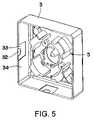
- FIG. 5is an enlarged perspective view of another cover for the box showing an alternate arrangement in which the slack cable storage spool is part of the cover instead of being removably attachable to the base.
- slack cable storage box 1 of the present inventionincluding a base 2 and a cover 3 removably attachable to the base to provide an accessible enclosure for a slack cable storage spool 5 for storing a length of cable within the enclosure.
- slack cable storage boxesmay be mounted on corridor walls adjacent any number of multiple dwelling units in an apartment or condominium building or the like to provide enough slack cable to run network or broadband cable service to any of the units upon request.
- Base 2may be secured to the corridor wall of such multiple dwelling units as by inserting suitable fasteners such as screws or nails or the like through slots 6 in the back wall 7 of the base (see FIGS. 2 and 4 ) for anchoring into the wall structure.
- suitable fastenerssuch as screws or nails or the like
- adhesive or other suitable meansmay be used to secure the base to the wall structure.
- Cover 3may be removably attached to base 2 in any convenient manner, for example, by providing one or more axially outwardly extending attachment posts 8 on the base back wall 7 containing threaded bores 9 for threaded receipt of fasteners extending through fastener openings 10 in the cover end face 11 .
- These fastener openings 10may be located within a recess 15 in the outer surface 16 of the cover end face 11 for concealment by a decorative faceplate 17 that may be snap fitted into slots 18 in the sides of the recess (see FIG. 2 ).
- any number of differently decorated faceplatesmay be interchangeably receivable within the recess to give the box a different appearance or motif.
- the boxes and/or faceplatesmay be made in different colors, sizes and shapes as desired.
- the slack cable storage spool 5is shown in FIGS. 2-4 removably attachable to the base as by inserting fasteners (not shown) through circumferentially spaced holes 20 in the spool hub 21 radially inwardly of the arcuate spool segments 22 for threaded engagement in threaded bores 23 in the base back wall 7 .
- the spool 5may be secured within the cover 3 as shown in FIG. 5 .
- an advantage in removably attaching the spool to the base instead of inside the coveris that the installer can then more easily make certain that the slack cable is properly stored on the spool within the base before the cover is attached to the base to eliminate any chance of pinching the cable during such cover attachment.
- Making the spool 5 detachable from the basealso has the advantage that the slack cable can be more easily wrapped around the spool while the spool is removed from the base.
- the spoolmay be removed from the base in order to facilitate punching or otherwise forming a hole at least partway through the wall structure of the unit through a relatively large opening 25 in the base back wall 7 preparatory to feeding the cable through the hole into the unit.
- each slack cable storage box 1may be varied depending on the amount of slack cable that is required to be stored in each box.
- the arcuate spool segments 22 inside the boxmaintain a minimum bend radius of the cable to prevent breakage which for example in the case of optical fiber is on the order of ten times the fiber diameter.
- the spool 5has an axial open center 26 that at least partially overlies the enlarged opening 25 in the base back wall 7 when the spool is attached to the base as shown in FIG. 4 to permit the leading end of the slack cable (not shown) to be fed through the spool open center and the center opening in the base back wall into a hole when made in the building wall structure.
- the size of the axial open center 26 of the spool 5is less than half the size of the enlarged center opening 25 in the base back wall 7 .
- a plurality of circumferentially spaced docking station brackets 27may extend axially outwardly from the inner diameter of the spool hub 21 for docking a suitable connector (not shown) attached to the free end of the slack cable while the slack cable is stored within the box.
- Individual continuous lengths of cablemay be run from a main multiple dwelling unit box located for example on the outside of the building or in a closet or stairwell or other convenient location in the building, to each of the slack cable storage boxes 1 through suitable raceways or moldings attachable to the building wall structure, with sufficient slack cable being provided for wrapping around the spool in each box to be able to run network or broadband cable service into each unit if requested.
- Suitable slots or openings 30may be provided in one or more side walls 31 of the base back wall 7 (see FIGS. 2-4 ) for entry of the cable and associated raceway or molding into the box.
- different size knockouts 32 , 33may be provided in one or more of the cover side walls 34 (see FIG. 5 ) that may be selectively removed for accommodating different size raceways or moldings when the cover is attached to the base.
- the cover 3 and spool 5 of the associated slack cable storage box 1are removed from the base 2 for ease of punching or otherwise forming a hole through the portion of the wall structure of the unit that is accessible through the enlarged opening 25 in the base back wall 7 .
- the connector on the free end of the cable(not shown) is removed from the docking station brackets 27 and the desired amount of cable needed is uncoiled from the spool and fished through the hole in the wall structure or dropped down inside the wall to a box in the unit where the broadband connection is to be made.
- Circumferentially spaced gaps 35 between the spool segments 22provide for easy cable access to the open center 26 of the spool through any one of the gaps. If all of the slack cable is used to make the broadband connection within the unit, the spool may be discarded rather than reattached to the base before reattaching the cover to the base if desired.
Landscapes
- Physics & Mathematics (AREA)
- General Physics & Mathematics (AREA)
- Optics & Photonics (AREA)
- Engineering & Computer Science (AREA)
- Civil Engineering (AREA)
- Structural Engineering (AREA)
- Installation Of Indoor Wiring (AREA)
- Suspension Of Electric Lines Or Cables (AREA)
Abstract
Description
Claims (14)
Priority Applications (1)
| Application Number | Priority Date | Filing Date | Title |
|---|---|---|---|
| US11/412,561US7477829B2 (en) | 2006-04-27 | 2006-04-27 | Slack cable storage box |
Applications Claiming Priority (1)
| Application Number | Priority Date | Filing Date | Title |
|---|---|---|---|
| US11/412,561US7477829B2 (en) | 2006-04-27 | 2006-04-27 | Slack cable storage box |
Publications (2)
| Publication Number | Publication Date |
|---|---|
| US20070274659A1 US20070274659A1 (en) | 2007-11-29 |
| US7477829B2true US7477829B2 (en) | 2009-01-13 |
Family
ID=38749619
Family Applications (1)
| Application Number | Title | Priority Date | Filing Date |
|---|---|---|---|
| US11/412,561ActiveUS7477829B2 (en) | 2006-04-27 | 2006-04-27 | Slack cable storage box |
Country Status (1)
| Country | Link |
|---|---|
| US (1) | US7477829B2 (en) |
Cited By (21)
| Publication number | Priority date | Publication date | Assignee | Title |
|---|---|---|---|---|
| US20100310224A1 (en)* | 2007-08-06 | 2010-12-09 | Adc Telecommunications, Inc. | Fiber optic enclosure with internal cable spool |
| US20110000710A1 (en)* | 2008-07-03 | 2011-01-06 | Panduit Corp. | In-ceiling zone cabling enclosure |
| US20120292096A1 (en)* | 2011-05-19 | 2012-11-22 | Communication Systems, Inc. | Modular plug and play connectivity platform |
| US8837940B2 (en) | 2010-04-14 | 2014-09-16 | Adc Telecommunications, Inc. | Methods and systems for distributing fiber optic telecommunication services to local areas and for supporting distributed antenna systems |
| USRE45153E1 (en) | 2007-01-13 | 2014-09-23 | Adc Telecommunications, Inc. | Fiber optic cable distribution box |
| WO2015042242A1 (en)* | 2013-09-18 | 2015-03-26 | Hubbell Incorporated | Fiber cable and drop wire organizer |
| US9057860B2 (en) | 2007-05-07 | 2015-06-16 | Adc Telecommunications, Inc. | Fiber optic enclosure with external cable spool |
| US9188760B2 (en) | 2011-12-22 | 2015-11-17 | Adc Telecommunications, Inc. | Mini rapid delivery spool |
| US20160033733A1 (en)* | 2014-08-04 | 2016-02-04 | Ofs Fitel, Llc | Compact storage and distribution module for optical fiber and cable |
| US9261663B2 (en) | 2010-06-18 | 2016-02-16 | Adc Communications (Shanghai) Co., Ltd. | Fiber optic distribution terminal and method of deploying fiber distribution cable |
| US9528289B2 (en) | 2014-08-15 | 2016-12-27 | Hubbell Incorporated | Apparatus for supporting cable |
| US9645344B2 (en) | 2015-08-11 | 2017-05-09 | Hubbell Incorporated | Inverted cable storage device |
| US9660430B2 (en) | 2011-03-29 | 2017-05-23 | Ppc Broadband, Inc. | Configurable enclosure |
| US9790051B2 (en) | 2013-06-18 | 2017-10-17 | Commscope Technologies Llc | Conductor spool and optical fiber / electrical composite cable with conductor spool assembly |
| US9995898B2 (en) | 2010-06-23 | 2018-06-12 | Commscope Technologies Llc | Telecommunications assembly |
| US10371914B2 (en) | 2011-06-24 | 2019-08-06 | Commscope Technologies Llc | Fiber termination enclosure with modular plate assemblies |
| US10545305B2 (en) | 2012-12-19 | 2020-01-28 | CommScope Connectivity Belgium BVBA | Distribution device with incrementally added splitters |
| US10833496B2 (en) | 2011-03-29 | 2020-11-10 | Ppc Broadband, Inc. | Configurable enclosure |
| US20220269027A1 (en)* | 2019-09-06 | 2022-08-25 | Corning Research & Development Corporation | Cable seal and strain relief assembly |
| US11899261B2 (en) | 2020-06-22 | 2024-02-13 | Corning Research & Development Corporation | Cable seal and strain relief assembly |
| US12197024B2 (en) | 2019-09-06 | 2025-01-14 | Corning Research & Development Corporation | Cable seal and strain relief assembly |
Families Citing this family (9)
| Publication number | Priority date | Publication date | Assignee | Title |
|---|---|---|---|---|
| WO2010001155A2 (en)* | 2008-07-04 | 2010-01-07 | Tyco Electronics Raychem Bvba | Improvements in or relating to optical fibre distribution systems |
| JP5471896B2 (en)* | 2010-06-30 | 2014-04-16 | 株式会社富士通ゼネラル | Air conditioner refrigerant branching unit |
| IT1404046B1 (en)* | 2011-02-08 | 2013-11-08 | Sirti Spa | DISTRIBUTION SYSTEM OF OPTICAL CABLES IN A BUILDING. |
| US9052489B2 (en)* | 2013-02-08 | 2015-06-09 | All Systems Broadband, Inc. | Fiber shelf break-out plate |
| US10197757B2 (en)* | 2015-05-15 | 2019-02-05 | Hubbell Incorporated | Cable storage wheels |
| CN105785530B (en)* | 2016-04-27 | 2019-01-08 | 李雨露 | A kind of winding box of fiber optic cable |
| US11320616B2 (en)* | 2018-05-31 | 2022-05-03 | Hubbell Incorporated | Utility enclosures with cable storage systems |
| CA3142274A1 (en) | 2019-06-04 | 2020-12-10 | Ppc Broadband Fiber Ltd. | Enclosure box for fiber optic cable |
| WO2023278884A1 (en) | 2021-07-02 | 2023-01-05 | Ppc Broadband Fiber Ltd. | Spool enclosure for a terminal |
Citations (5)
| Publication number | Priority date | Publication date | Assignee | Title |
|---|---|---|---|---|
| US5947765A (en)* | 1994-11-04 | 1999-09-07 | The Siemon Company | Multimedia outlet |
| US20050145522A1 (en)* | 2003-12-24 | 2005-07-07 | Bloodworth Stephen G. | Fiber optic drop cable slack storage receptacle |
| US20060217231A1 (en)* | 2005-03-24 | 2006-09-28 | Walkstyles, Inc. | Interactive exercise device and system |
| US20060254817A1 (en)* | 2002-08-09 | 2006-11-16 | Panduit Corp. | Multimedia outlet box |
| US20070086721A1 (en)* | 2005-07-14 | 2007-04-19 | Afl Telecommunications Llc | Optical fiber splice enclosure |
- 2006
- 2006-04-27USUS11/412,561patent/US7477829B2/enactiveActive
Patent Citations (5)
| Publication number | Priority date | Publication date | Assignee | Title |
|---|---|---|---|---|
| US5947765A (en)* | 1994-11-04 | 1999-09-07 | The Siemon Company | Multimedia outlet |
| US20060254817A1 (en)* | 2002-08-09 | 2006-11-16 | Panduit Corp. | Multimedia outlet box |
| US20050145522A1 (en)* | 2003-12-24 | 2005-07-07 | Bloodworth Stephen G. | Fiber optic drop cable slack storage receptacle |
| US20060217231A1 (en)* | 2005-03-24 | 2006-09-28 | Walkstyles, Inc. | Interactive exercise device and system |
| US20070086721A1 (en)* | 2005-07-14 | 2007-04-19 | Afl Telecommunications Llc | Optical fiber splice enclosure |
Cited By (72)
| Publication number | Priority date | Publication date | Assignee | Title |
|---|---|---|---|---|
| USRE46255E1 (en) | 2007-01-13 | 2016-12-27 | Commscope Technologies Llc | Fiber optic cable distribution box |
| USRE49385E1 (en) | 2007-01-13 | 2023-01-24 | Commscope Technologies Llc | Fiber optic cable distribution box |
| USRE48063E1 (en) | 2007-01-13 | 2020-06-23 | Commscope Technologies Llc | Fiber optic cable distribution box |
| USRE45153E1 (en) | 2007-01-13 | 2014-09-23 | Adc Telecommunications, Inc. | Fiber optic cable distribution box |
| US10627592B2 (en) | 2007-05-07 | 2020-04-21 | Commscope Technologies Llc | Fiber optic assembly with cable spool |
| US10788642B2 (en) | 2007-05-07 | 2020-09-29 | Commscope Technologies Llc | Fiber optic assembly with cable storage arrangement |
| US11009671B2 (en) | 2007-05-07 | 2021-05-18 | Commscope Technologies Llc | Fiber optic assembly with cable storage arrangement |
| US9057860B2 (en) | 2007-05-07 | 2015-06-16 | Adc Telecommunications, Inc. | Fiber optic enclosure with external cable spool |
| US12235506B2 (en) | 2007-05-07 | 2025-02-25 | Commscope Technologies Llc | Fiber optic enclosure with external cable spool |
| US10996418B2 (en) | 2007-08-06 | 2021-05-04 | Commscope Technologies Llc | Connecting subscribers to a fiber optic network using a cable spool |
| US10234648B2 (en) | 2007-08-06 | 2019-03-19 | Commscope Technologies Llc | Fiber optic enclosure with internal cable spool |
| US8891931B2 (en) | 2007-08-06 | 2014-11-18 | Adc Telecommunications, Inc. | Fiber optic enclosure with internal cable spool |
| US8494333B2 (en) | 2007-08-06 | 2013-07-23 | Adc Telecommunications, Inc. | Dispensing cable from an internal cable spool of a fiber optic enclosure |
| US12253734B2 (en) | 2007-08-06 | 2025-03-18 | Commscope Technologies Llc | Fiber optic enclosure with internal cable spool |
| US10606015B2 (en) | 2007-08-06 | 2020-03-31 | Commscope Technologies Llc | Fiber optic payout assembly including cable spool |
| US20100310224A1 (en)* | 2007-08-06 | 2010-12-09 | Adc Telecommunications, Inc. | Fiber optic enclosure with internal cable spool |
| US8705929B2 (en) | 2007-08-06 | 2014-04-22 | Adc Telecommunications, Inc. | Fiber optic enclosure with internal cable spool |
| US11573390B2 (en) | 2007-08-06 | 2023-02-07 | Commscope Technologies Llc | Fiber optic enclosure with internal cable spool |
| US9261666B2 (en) | 2007-08-06 | 2016-02-16 | Commscope Technologies Llc | Fiber optic enclosure with internal cable spool |
| US8189984B2 (en) | 2007-08-06 | 2012-05-29 | Adc Telecommunications, Inc. | Fiber optic enclosure with internal cable spool |
| US10606017B2 (en) | 2007-08-06 | 2020-03-31 | Commscope Technologies Llc | Fiber optic payout assembly including cable spool |
| US10996417B2 (en) | 2007-08-06 | 2021-05-04 | Commscope Technologies Llc | Fiber optic enclosure with internal cable spool and movable cover |
| US12019301B2 (en) | 2007-08-06 | 2024-06-25 | Commscope Technologies Llc | Fiber optic enclosure with internal cable spool |
| US10895705B2 (en) | 2007-08-06 | 2021-01-19 | Commscope Technologies Llc | Fiber optic enclosure with internal cable spool |
| US10247897B2 (en) | 2007-08-06 | 2019-04-02 | Commscope Technologies Llc | Fiber optic enclosure with internal cable spool |
| US10495836B2 (en) | 2007-08-06 | 2019-12-03 | Commscope Technologies Llc | Fiber optic payout assembly including cable spool |
| US20110158599A1 (en)* | 2007-08-06 | 2011-06-30 | Adc Telecommunications, Inc. | Fiber optic enclosure with internal cable spool |
| US9606319B2 (en) | 2007-08-06 | 2017-03-28 | Commscope Technologies Llc | Fiber optic enclosure with internal cable spool |
| US10712518B2 (en) | 2007-08-06 | 2020-07-14 | Commscope Technologies Llc | Fiber optic enclosure with lockable internal cable spool |
| US7894701B2 (en)* | 2007-08-06 | 2011-02-22 | Adc Telecommunications, Inc. | Fiber optic enclosure with internal cable spool |
| US7956284B2 (en)* | 2008-07-03 | 2011-06-07 | Panduit Corp. | In-ceiling zone cabling enclosure |
| US20110000710A1 (en)* | 2008-07-03 | 2011-01-06 | Panduit Corp. | In-ceiling zone cabling enclosure |
| US8837940B2 (en) | 2010-04-14 | 2014-09-16 | Adc Telecommunications, Inc. | Methods and systems for distributing fiber optic telecommunication services to local areas and for supporting distributed antenna systems |
| US10819444B2 (en) | 2010-04-14 | 2020-10-27 | Commscope Technologies Llc | Methods and systems for distributing fiber optic telecommunication services to local areas and for supporting distributed antenna systems |
| US9414137B2 (en) | 2010-04-14 | 2016-08-09 | Commscope Technologies Llc | Methods and systems for distributing fiber optic telecommunication services to local areas and for supporting distributed antenna systems |
| US9261663B2 (en) | 2010-06-18 | 2016-02-16 | Adc Communications (Shanghai) Co., Ltd. | Fiber optic distribution terminal and method of deploying fiber distribution cable |
| US9563031B2 (en) | 2010-06-18 | 2017-02-07 | Adc Telecommunications (Shanghai) Distribution Co., Ltd. | Fiber optic enclosure with internal cable spool |
| US10884211B2 (en) | 2010-06-23 | 2021-01-05 | Commscope Technologies Llc | Telecommunications assembly |
| US11789226B2 (en) | 2010-06-23 | 2023-10-17 | Commscope Technologies Llc | Telecommunications assembly |
| US11402595B2 (en) | 2010-06-23 | 2022-08-02 | Commscope Technologies Llc | Telecommunications assembly |
| US10268014B2 (en) | 2010-06-23 | 2019-04-23 | Commscope Technologies Llc | Telecommunications assembly |
| US12235504B2 (en) | 2010-06-23 | 2025-02-25 | Commscope Technologies Llc | Telecommunications assembly |
| US10126516B1 (en) | 2010-06-23 | 2018-11-13 | Commscope Technologies Llc | Telecommunications assembly |
| US9995898B2 (en) | 2010-06-23 | 2018-06-12 | Commscope Technologies Llc | Telecommunications assembly |
| US10627593B2 (en) | 2010-06-23 | 2020-04-21 | Commscope Technologies Llc | Telecommunications assembly |
| US10833496B2 (en) | 2011-03-29 | 2020-11-10 | Ppc Broadband, Inc. | Configurable enclosure |
| US10461516B2 (en) | 2011-03-29 | 2019-10-29 | Ppc Broadband, Inc. | Configurable enclosure |
| US9660430B2 (en) | 2011-03-29 | 2017-05-23 | Ppc Broadband, Inc. | Configurable enclosure |
| US9134496B2 (en)* | 2011-05-19 | 2015-09-15 | Communication Systems, Inc. | Modular plug and play connectivity platform |
| US20120292096A1 (en)* | 2011-05-19 | 2012-11-22 | Communication Systems, Inc. | Modular plug and play connectivity platform |
| US11988883B2 (en) | 2011-06-24 | 2024-05-21 | Commscope Technologies Llc | Fiber termination enclosure with modular plate assemblies |
| US10502916B2 (en) | 2011-06-24 | 2019-12-10 | Commscope Technologies Llc | Fiber termination enclosure with modular plate assemblies |
| US10371914B2 (en) | 2011-06-24 | 2019-08-06 | Commscope Technologies Llc | Fiber termination enclosure with modular plate assemblies |
| US11327262B2 (en) | 2011-06-24 | 2022-05-10 | Commscope Technologies Llc | Fiber termination enclosure with modular plate assemblies |
| US11624884B2 (en) | 2011-06-24 | 2023-04-11 | Commscope Technologies Llc | Fiber termination enclosure with modular plate assemblies |
| US10935744B2 (en) | 2011-06-24 | 2021-03-02 | Commscope Technologies Llc | Fiber termination enclosure with modular plate assemblies |
| US9523834B2 (en) | 2011-12-22 | 2016-12-20 | Commscope Technologies Llc | Fiber optic enclosure |
| US9188760B2 (en) | 2011-12-22 | 2015-11-17 | Adc Telecommunications, Inc. | Mini rapid delivery spool |
| US10545305B2 (en) | 2012-12-19 | 2020-01-28 | CommScope Connectivity Belgium BVBA | Distribution device with incrementally added splitters |
| US9790051B2 (en) | 2013-06-18 | 2017-10-17 | Commscope Technologies Llc | Conductor spool and optical fiber / electrical composite cable with conductor spool assembly |
| US9581783B2 (en) | 2013-09-18 | 2017-02-28 | Hubbell Incorporated | Fiber cable and drop wire organizer |
| WO2015042242A1 (en)* | 2013-09-18 | 2015-03-26 | Hubbell Incorporated | Fiber cable and drop wire organizer |
| US9366836B2 (en) | 2013-09-18 | 2016-06-14 | Hubbell Incorporated | Fiber cable and drop wire organizer |
| US20160033733A1 (en)* | 2014-08-04 | 2016-02-04 | Ofs Fitel, Llc | Compact storage and distribution module for optical fiber and cable |
| US9429729B2 (en)* | 2014-08-04 | 2016-08-30 | Ofs Fitel, Llc | Compact storage and distribution module for optical fiber and cable |
| US9528289B2 (en) | 2014-08-15 | 2016-12-27 | Hubbell Incorporated | Apparatus for supporting cable |
| US10215946B2 (en) | 2014-08-15 | 2019-02-26 | Hubbell Incorporated | Apparatus for supporting cable |
| US9645344B2 (en) | 2015-08-11 | 2017-05-09 | Hubbell Incorporated | Inverted cable storage device |
| US11899265B2 (en)* | 2019-09-06 | 2024-02-13 | Corning Research & Development Corporation | Cable seal and strain relief assembly |
| US12197024B2 (en) | 2019-09-06 | 2025-01-14 | Corning Research & Development Corporation | Cable seal and strain relief assembly |
| US20220269027A1 (en)* | 2019-09-06 | 2022-08-25 | Corning Research & Development Corporation | Cable seal and strain relief assembly |
| US11899261B2 (en) | 2020-06-22 | 2024-02-13 | Corning Research & Development Corporation | Cable seal and strain relief assembly |
Also Published As
| Publication number | Publication date |
|---|---|
| US20070274659A1 (en) | 2007-11-29 |
Similar Documents
| Publication | Publication Date | Title |
|---|---|---|
| US7477829B2 (en) | Slack cable storage box | |
| US7359611B1 (en) | Slack cable storage box with adjustable height spools | |
| US7000746B2 (en) | Electric cord reel | |
| US20140161411A1 (en) | Surface-mountable enclosure | |
| CA2366639C (en) | Fiber optic cable outlet box | |
| US20210072484A1 (en) | Cable storage arrangement | |
| US20160099555A1 (en) | Universal Box Mounting Adapter and System | |
| US9429729B2 (en) | Compact storage and distribution module for optical fiber and cable | |
| EP2989494B1 (en) | Device, assembly and method for securing and retaining an optical cable | |
| US20020096347A1 (en) | Glide assembly for conduit bodies | |
| US11237349B2 (en) | Cable spool and storage | |
| MX2008010552A (en) | Cable junction box with provision for service loops. | |
| US9874712B2 (en) | Module for optical fiber installation and storage at customer premises | |
| US20030168545A1 (en) | Wire container | |
| US6710244B1 (en) | Base board system for installing wiring and method therefor | |
| US20130117993A1 (en) | Conduit divider in the form of a cable with fabric sleeve | |
| RU2575476C2 (en) | Surface mount box | |
| US7936961B2 (en) | Hidden drop storage device | |
| JPH10258970A (en) | Optical fiber winding device and storage device | |
| JP3211206U (en) | Conversion adapter fixture | |
| JP3914290B2 (en) | Cable access box | |
| CN206818943U (en) | Unification of three nets fiber cable cross connection box | |
| GB2629345A (en) | Data cable reel and data cable wall box assembly | |
| JP2008242460A (en) | Wall-mountable optical fiber and cable treatment apparatus | |
| TH73558A (en) | Cabling equipment for optical fibers |
Legal Events
| Date | Code | Title | Description |
|---|---|---|---|
| AS | Assignment | Owner name:MULTILINK, INC., OHIO Free format text:ASSIGNMENT OF ASSIGNORS INTEREST;ASSIGNOR:KAPLAN, STEVEN E.;REEL/FRAME:017613/0455 Effective date:20060426 | |
| STCF | Information on status: patent grant | Free format text:PATENTED CASE | |
| FPAY | Fee payment | Year of fee payment:4 | |
| AS | Assignment | Owner name:WELLS FARGO BANK, NATIONAL ASSOCIATION, OHIO Free format text:SECURITY AGREEMENT;ASSIGNOR:MULTILINK INC.;REEL/FRAME:029769/0395 Effective date:20130125 | |
| AS | Assignment | Owner name:FIRST NIAGARA COMMERCIAL FINANCE, INC., MASSACHUSE Free format text:SECURITY INTEREST;ASSIGNOR:MULTILINK INC.;REEL/FRAME:035548/0434 Effective date:20150420 | |
| FPAY | Fee payment | Year of fee payment:8 | |
| FEPP | Fee payment procedure | Free format text:MAINTENANCE FEE REMINDER MAILED (ORIGINAL EVENT CODE: REM.); ENTITY STATUS OF PATENT OWNER: SMALL ENTITY | |
| FEPP | Fee payment procedure | Free format text:11.5 YR SURCHARGE- LATE PMT W/IN 6 MO, SMALL ENTITY (ORIGINAL EVENT CODE: M2556); ENTITY STATUS OF PATENT OWNER: SMALL ENTITY | |
| MAFP | Maintenance fee payment | Free format text:PAYMENT OF MAINTENANCE FEE, 12TH YR, SMALL ENTITY (ORIGINAL EVENT CODE: M2553); ENTITY STATUS OF PATENT OWNER: SMALL ENTITY Year of fee payment:12 |