US7477781B1 - Method and apparatus for adaptive pixel correction of multi-color matrix - Google Patents
Method and apparatus for adaptive pixel correction of multi-color matrixDownload PDFInfo
- Publication number
- US7477781B1 US7477781B1US10/658,523US65852303AUS7477781B1US 7477781 B1US7477781 B1US 7477781B1US 65852303 AUS65852303 AUS 65852303AUS 7477781 B1US7477781 B1US 7477781B1
- Authority
- US
- United States
- Prior art keywords
- pixel
- vector
- value
- particular pixel
- color
- Prior art date
- Legal status (The legal status is an assumption and is not a legal conclusion. Google has not performed a legal analysis and makes no representation as to the accuracy of the status listed.)
- Active, expires
Links
- 239000011159matrix materialSubstances0.000titleclaimsabstractdescription38
- 238000000034methodMethods0.000titleclaimsabstractdescription36
- 238000012937correctionMethods0.000titleclaimsabstractdescription33
- 230000003044adaptive effectEffects0.000titleclaimsabstractdescription14
- 239000013598vectorSubstances0.000claimsabstractdescription116
- 230000007547defectEffects0.000claimsdescription96
- 230000002950deficientEffects0.000claimsdescription41
- 230000001419dependent effectEffects0.000claims1
- 238000012360testing methodMethods0.000description17
- 238000012545processingMethods0.000description9
- 239000003086colorantSubstances0.000description7
- 238000010586diagramMethods0.000description6
- 230000006870functionEffects0.000description6
- 230000002596correlated effectEffects0.000description5
- 238000013459approachMethods0.000description4
- 238000004590computer programMethods0.000description4
- 230000000875corresponding effectEffects0.000description3
- 230000008569processEffects0.000description3
- 230000000007visual effectEffects0.000description3
- 230000001276controlling effectEffects0.000description2
- 230000003247decreasing effectEffects0.000description2
- 238000001514detection methodMethods0.000description2
- 230000000694effectsEffects0.000description2
- 238000005259measurementMethods0.000description2
- 230000035945sensitivityEffects0.000description2
- 230000008901benefitEffects0.000description1
- 230000002457bidirectional effectEffects0.000description1
- 230000008859changeEffects0.000description1
- 230000000295complement effectEffects0.000description1
- 230000004069differentiationEffects0.000description1
- 230000012447hatchingEffects0.000description1
- 238000003384imaging methodMethods0.000description1
- 230000007246mechanismEffects0.000description1
- 229910044991metal oxideInorganic materials0.000description1
- 150000004706metal oxidesChemical class0.000description1
- 238000012986modificationMethods0.000description1
- 230000004048modificationEffects0.000description1
- 238000012544monitoring processMethods0.000description1
- 238000010606normalizationMethods0.000description1
- 230000008520organizationEffects0.000description1
- 230000004044responseEffects0.000description1
- 238000005070samplingMethods0.000description1
- 239000004065semiconductorSubstances0.000description1
- 238000012546transferMethods0.000description1
Images


Classifications
- H—ELECTRICITY
- H04—ELECTRIC COMMUNICATION TECHNIQUE
- H04N—PICTORIAL COMMUNICATION, e.g. TELEVISION
- H04N23/00—Cameras or camera modules comprising electronic image sensors; Control thereof
- H04N23/80—Camera processing pipelines; Components thereof
- H04N23/84—Camera processing pipelines; Components thereof for processing colour signals
- H04N23/843—Demosaicing, e.g. interpolating colour pixel values
- H—ELECTRICITY
- H04—ELECTRIC COMMUNICATION TECHNIQUE
- H04N—PICTORIAL COMMUNICATION, e.g. TELEVISION
- H04N25/00—Circuitry of solid-state image sensors [SSIS]; Control thereof
- H04N25/10—Circuitry of solid-state image sensors [SSIS]; Control thereof for transforming different wavelengths into image signals
- H04N25/11—Arrangement of colour filter arrays [CFA]; Filter mosaics
- H04N25/13—Arrangement of colour filter arrays [CFA]; Filter mosaics characterised by the spectral characteristics of the filter elements
- H04N25/134—Arrangement of colour filter arrays [CFA]; Filter mosaics characterised by the spectral characteristics of the filter elements based on three different wavelength filter elements
Definitions
- the present inventionrelates to a method and apparatus for adaptive pixel defect correction in a multi-color matrix based sensor arrangement through the assessing of edge continuity, a computer program and a computer program for controlling such method in a computer, and an image sensing facility encompassing such apparatus.
- the present inventionrelates to a method for adaptive pixel defect correction in a multi-color matrix-based sensor arrangement that assesses pixel values of a two-dimensional multi-pixel kernel around a particular pixel when determining an apparent defect value of said particular pixel.
- Multi-color and matrix-based sensor arrangementsare coming into rapidly expanding use, where the matrix size expressed in the number of pixels is increasing more or less exponentially in time, and the pixel size is generally decreasing likewise.
- the probability that a particular pixel will be defectiveis decreasing as well, but not at the same high rate, so that the overall probability for a matrix to have a defective pixel is on the rise.
- Haradauses a two-dimensional adaptive interpolation wherein a hard decision is made to select the pixels that will be averaged for finding the defective pixel. Moreover, no correlations across different color planes are used, so that the reference is based on a different perceptual model from the present invention.
- a method of adaptive pixel correction of a multi-color matrix from a sensorthat includes collecting pixel values, generating plural vectors, normalizing values and determining an estimated value.
- the collecting pixel valuescollects values of a two-dimensional multi-pixel kernel around a particular pixel from the multi-color matrix.
- the generating plural vectorsgenerates vectors from the kernel where each vector has the particular pixel as a central element.
- the normalizing valuesnormalizes values for nearest neighbor elements to the central element for each vector.
- the determining an estimated valuedetermines the value based on the normalized values.
- a system for adaptive pixel correction of a multi-color matrix from a sensorcomprising a processor and first, second, third and fourth modules.
- the first modulecontrols the processor to collect pixel values of a two-dimensional multi-pixel kernel around a particular pixel from the multi-color matrix.
- the second modulecontrols the processor to generate plural vectors from the kernel where each vector has the particular pixel as a central element.
- the third modulecontrols the processor to normalizing values for nearest neighbor elements to the central element for each vector.
- the fourth modulecontrols the processor to determine an estimated value based on the normalized values.
- the mediumincludes first, second, third and fourth modules.
- the first modulecontrols the processor to collect pixel values of a two-dimensional multi-pixel kernel around a particular pixel from the multi-color matrix.
- the second modulecontrols the processor to generate plural vectors from the kernel where each vector has the particular pixel as a central element.
- the third modulecontrols the processor to normalizing values for nearest neighbor elements to the central element for each vector.
- the fourth modulecontrols the processor to determine an estimated value based on the normalized values.
- FIG. 1a Bayer matrix of image points
- FIG. 2the sequential arrangement of the image points for processing
- FIGS. 3 a - 3 cthe pixel-based algorithm processing steps
- FIG. 4a flow diagram of a preferred algorithm
- FIG. 5a diagram showing the reason for t aliasing tolerance in the correction error test
- FIGS. 6 a , 6 bthe creation of limits for the error correction test
- FIGS. 7 a , 7 bexamples of the error correction test
- FIG. 8a flow diagram of a DSP pipeline with error correction test.
- the reconstruction of color pixel valuesis based on soft decisions in the various color planes, and in particular, by taking into account the spatial response of the human visual system.
- the results of the present inventionmay be applied as input to the co-pending application's invention, but such represents no express restriction.
- the present inventionminimizes perceptual error, utilizes pictorial properties to make intelligent solutions when correcting defective points, and can correct a wide range of shapes and sizes of a defect.
- defectsmay have the form of single pixels or small clusters.
- the defectsmay include a whole column or a relatively substantial part thereof. These defects have relatively high spatial frequencies and will often be prominently visible to a user or observer and therefore be unacceptable.
- the present inventionis, inter alia, based on recognizing the perceptual relevance of a user's expectation that edges which are present in the sensed image will generally be continuous, and that disturbance or interruption of such edges will often be due to disturbances of the sensor per se.
- the property of pictorial image R-G-B correlationcan be demonstrated by taking the gradient of each R, G, B image component and by analyzing where the gradients differ.
- an input image a[m,n, ⁇ ]that is a function of spatial m (horizontal), n (vertical) and R-G-B components ( ⁇ )
- m, n and ⁇are unit vectors.
- the R-G-B valuesare correlated within objects and along edges. This means that the rates of change of R, G, and B are substantially constant for a point in regions with low spatial frequency and also substantially constant along the edge direction in regions with high spatial frequency. Now ideally, one would like to find the edge direction and utilize the two neighboring pixels in that direction to estimate the defect pixel a[m0,n0].
- each non-Green pixelis exclusively surrounded by pixels of different colors. For Green pixels, four diagonal neighbors are Green indeed, but the other four neighbors are still non-Green.
- the R-G-B colors of an imageare locally correlated to each other even across the color differences. Therefore, although neighboring pixels may sample different colors, according to the invention they are still correlated to the defect pixel's color plane.
- the cross-color approachrepresents a particularly advantageous refinement.
- the aboveis exploited by calculating the gradient of the non-defect color plane on each side for each edge direction and by applying this gradient to the nearest known pixel of the same color as the defect on each side of the defect for each edge direction. We then correlate the nearest pixels to the defect pixel's color and acquire the nearest known data. Finally, we may select the edge direction by merely determining which two neighboring pixels of a given edge direction have the least difference in magnitude, once correlated to the defect pixel's color. In a relatively simplistic implementation, the defect value may be calculated as the arithmetic mean of those two pixels. However, a fuller realization of the invention entails to calculate the weighted sum of all neighboring pixels with their weights based on their alignment with the true edge direction.
- a methodexploits this cross-color approach to interpolating a defective pixel.
- the inventionalso relates to a computer program having program instructions for controlling a computer to implement a method that exploits this cross-color approach to interpolating a defective pixel, and to such computer program realized as a computer readable medium represented within a tangible read-only computer memory medium or being carried by an electrical signal.
- the inventionalso relates to an apparatus arranged for implementing a method that exploits this cross-color approach to interpolating a defective pixel and to an image sensing facility comprising such an apparatus. Further advantageous aspects of the invention are discussed herein.
- FIG. 1illustrates a Bayer matrix of image points for use with the present invention.
- the matrixhas Green pixels arranged according to a chessboard organization. The remaining pixels have been used for Red pixels in odd rows and Blue pixels in even rows.
- the dashed squarefor example corresponds with a Blue pixel
- FIG. 2illustrates the sequential arrangement of the image points for processing. Along a row, they are presented in sequence, followed by the next row presented in the same sequential order. It would be clear from this Figure, as to how the pixels pertaining to a particular kernel shape would be organized for use in the processing hereinafter.
- the sampled input image a[m,n] of M columns and N rows in totallets each image point in sequence be tested against the defect map. Finding a defect will initiate the correction thereof.
- the defect properwill often be signaled by a defect map detection or a defect detection apparatus. Such is state of the art.
- the algorithm of adaptive pixel correction of a multi-color matrix from a sensorincludes the following.
- Pixel values from the multi-color matrix a[m,n]are input to the algorithm column by column within a row and then advancing one row after the last column is input, and the column by column input for the row is repeated (see FIG. 2 ).
- 7 rowsare buffered locally in order to process a 7 ⁇ 7 matrix kernel.
- a particular pixel, designated to be at m 0 , n 0is a pixel 4 columns behind and 4 rows behind the current pixel input. This particular pixel is the pixel under attention.
- Pixel values of a two-dimensional multi-pixel kernel around the particular pixelare extracted from the multi-color matrix to form a 7 ⁇ 7 matrix kernel with the particular pixel being central to the kernel. The intended color of the central pixel is assessed.
- the eight nearest neighbor pixels to the particular pixelform parts of four directional “vectors.” Each directional vector includes 7 pixels disposed in a straight line that passes through one nearest neighbor pixel, then through the particular pixel, and then through another nearest neighbor pixel.
- the four directional “vectors”are derived at respective angles that differ by 45°, and which vectors are centered at the particular pixel.
- the central pixelis under attention, is located at m 0 , n 0 and has a value of a[m 0 , n 0 ].
- the four vectorshave seven elements each, where each element is indexed by nn which may vary over a range from ⁇ 3 to +3.
- the defect mapindicates a column is defective at the central image point, the vertical vector in question is thereupon ignored, thus reducing the number of vectors to process from four to three. This generally is only relevant for a CCD sensor.
- Uncorrected error elements in vectorsare elements corresponding to pixels in the multi-color matrix from the sensor that are marked as defective. Because all defects are corrected in a column by column then row by row sequence, defects in pixels that have been processed previously should have been corrected already, but defects in pixels that have yet to be processed may have an uncorrected error. Such uncorrected error pixels in the kernel (elements in the vectors) are in addition to the particular pixel under attention (i.e., the defect point herein) that is located at m 0 , n 0 .
- the uncorrected error element at nn defectis “filled in” with a value so that a value can be estimated for the particular pixel under attention (i.e., the defect point herein) that is located at m 0 , n 0 .
- vector elements corresponding to pixels nearest to the pixel under attention at m 0 , n 0are normalized to the color plane of the defect. Normalization is accomplished by calculating the gradient of the non-defect color plane on each side of d i [0] and by applying the gradient to the nearest sampled elements d i [ ⁇ 2] and d i [+2] of the same color plane as the particular pixel under attention. The procedure is carried out as follows for each vector d i .
- ⁇ i [ ⁇ 1] and ⁇ i [+1]are the single-sided single-color gradients on the minus and plus side of the particular pixel under attention, respectively.
- theses gradients from the non-defect color planeare correlated to the pixels in the defect color plane that are nearest to the particular pixel under attention. This is accomplished by defining new vector elements to estimate the nearest sample elements in the defect color plane to the particular pixel under attention.
- i [ ⁇ 1] and i [+1]are the single-sided normalized vector elements on the minus and plus side of the particular pixel under attention, respectively.
- the nearest sampled elements of the same color plane as the particular pixel under attentionare sample measurement found at d i [ ⁇ 2] and d i [+2].
- the values of the directional vector elements from d i [ ⁇ 2] to d i [+2], omitting only d i [0]have been either sampled or estimated, and the vectors can next be used to determine an edge vector.
- FIGS. 3 a through 3 cThe procedure of normalizing the non-defect color plane pixels has been illustrated in FIGS. 3 a through 3 c.
- the parameter kcan be adjusted to modify the algorithm's sensitivity to the differences in d i [nn], where the sensitivity increases with the value of the exponent k.
- the vector aligned closest to the edge directioni.e., the minimum value of the absolute difference
- this edge vectorbe symbolized by d i ⁇ [nn].
- this step of finding a weighted measure for the edge directionis indicated by the arrow.
- FIGS. 3 a - 3 cillustrate the various pixel-based algorithm processing steps for normalizing.
- the bar at the right side of the figuresrelates the various hatching patterns of the kernel pixels to a numerical value of the color value which is shown at the right side of the bar.
- FIG. 3 ais a Bayer image with its associated edge vectors d 1 , d 2 , d 3 and d 4 in a 7 ⁇ 7 pixel kernel K.
- a single defect at a[m 0 , n 0 ]has been indicated by a white pixel.
- FIG. 3 bthe vector pixels near the defect have been shown in an enlarged manner; the ones marked with a black dot will not be considered for the defect pixel.
- FIG. 3 cthe neighboring pixels have been normalized to the color plane of the defective pixel.
- the edge directionis evidently vertical and shown in the figure as an arrow, thereby allowing the interpolating of the defective point.
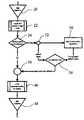
- FIG. 4illustrates a flow diagram of a preferred algorithm.
- element 20is the DSP pipeline of the arrangement which is fed by an image sensor not shown and which comprises an appropriate amount of processing and memory facilities.
- Block 22represents the captured Bayer image data, inasfar as presently used.
- block 24the Bayer image data are checked for occurrence of a defect point. If yes, the system goes to the defect correction algorithm in block 50 .
- block 26the data of a 7 ⁇ 7 kernel centered at the defect are constituted.
- the four angle vectors thereofare produced.
- theseare checked for existence of a column defect. If yes, in block 34 , the vertical vector is dropped from further consideration.
- the remaining vectorsare checked for defects. If present, in block 36 these defects are interpolated. Then, either from block 32 , or from block 36 , in block 38 the vector points are normalized to the defect color plane through using gradients.
- block 40a single angular vector is selected, followed in block 42 by linear interpolating the defect from the angular vector.
- block 50is left with an interpolated defect value, that in mixer or accumulator facility 44 is combined with the information pertaining to all those situations where no defect point was encountered (block 24 ). This terminates the present algorithm.
- block 46other color reconstruction steps and various further processing may be effected.
- the processed informationreturns to the DSP pipeline in block 48 .
- the algorithmis evaluated on the basis of the human visual system and the Nyquist theorem. Often, a defect value will be acceptable in high-frequency regions because the visual system's differentiation ability changes with spatial frequency. Now, the above defect correction algorithm attempts to estimate a defective pixel. According to Nyquist, the highest non-aliased frequency (the Nyquist frequency f N ) that the Red, Green, and Blue pixels may sample is equal to half the maximum frequency they may record in a particular direction.
- Nyquistthe highest non-aliased frequency that the Red, Green, and Blue pixels may sample is equal to half the maximum frequency they may record in a particular direction.
- the highest recordable unalised frequencyis at a minimum V 2 of a cycle per pixel (i.e., the full period is 2 pixels long) in a given sample color plane.
- V 2the full period is 2 pixels long
- redthe Nyquist frequency would be 1 ⁇ 4 of a cycle per pixel (i.e., the full period is 4 pixels long).
- the occurrence of a defective pixelwill further lower the Nyquist frequency by half such that the maximum recordable non-aliased frequency would be 1 ⁇ 8 cycle per pixel (i.e., a full period is 8 pixels long).
- the CFAi.e., color filter array
- the CFAhas a minimum sampling rate of 1 ⁇ 4 cycle per pixel (i.e., the full period is 4 pixels long).
- the correlationis done through using gradients measured at a two-pixel spacing and so could result in a zero gradient through aliasing: then it would be impossible to correlate the non-defect colors. This could lead to a 100% deviation error.
- the defect pixelitself deviates only by 10%, using it uncorrected would have been better. Therefore, the typical magnitude of a pixel's defect may be used to decide whether the corrected or rather the uncorrected value of the pixel is a better approximation.
- FIG. 5is a diagram showing the reason for aliasing tolerance value t in the correction error test.
- the pixelshave been shown with their matrix colors Red R and Green G, respectively, and their actual values in the vertical direction.
- the sampled value a for the defect pixelis shown by a large “X”.
- the horizontal arrow 100has a span of four pixel distances. If the limit for the distance from the sampled value a for the defect pixel to the correction algorithm's estimate â is restricted to the maximum defect deviation ⁇ , the estimate a would be rejected in favor of keeping the sampled value a. Nevertheless, the estimate â is closer to the true but unknown value a′ in this example due to the apex (high frequency content). Therefore, the tolerance value t, which is a function of the local Nyquist frequency, should be added to the maximum defect deviation ⁇ to ensure that defect corrections at apex locations will not be rejected when they would, in effect, be acceptable.
- FIG. 6illustrates the creation of limits for the error correction test.
- the testis constructed as follows. Let the sampled value for the defective pixel be a and the true but unknown scene value for the defective pixel be a′ in an image with an available dynamic range C (e.g., such as 255 for an 8-bit image). The algorithm would then produce an estimate â.
- the Nyquist frequencyis 1 ⁇ 8 cycle per pixel.
- a Red pixelis defective, so that the Red pixels are locally sampled only every four pixels.
- the maximum recordable frequencyis 1 ⁇ 4 cycle per pixel, and the Nyquist frequency f N is 1 ⁇ 2 of that. Since the adaptive edge algorithm uses gradients to calculate an estimate of the pixel value for the defect pixel, the maximum non-aliased signal would be 1 ⁇ 8.
- the correctionwill over-estimate the value for the defect pixel, although it can never exceed C/16.
- the errorwould not exceed f N C, no system will have a perfect Modulation Transfer Function MTF in practice.
- the MTFmay be either theoretically computed or actually measured.
- FIGS. 6 a and 6 billustrate the creation of limits for the error correction test.
- FIG. 6 aillustrates the developing of an acceptance range OK for the estimated value â for a sampled value a of a defect pixel that differs from the true scene value a′ by ⁇ with an aliasing tolerance of t and a scene dynamic range of C.
- the estimated valueis accepted (OK) if the difference with the scene value a′ lies between 0 and ⁇ C, and the estimated value is also accepted (OK) even though the difference is greater than ⁇ C, but only if it is greater by no more than the aliasing tolerance tC.
- the estimated value âis rejected (NOK).
- FIG. 6 billustrates the range of values for the estimated value â, centered about the sampled value a, that can be accepted (OK). Any estimated value â found to deviate from the measured sample value a for a defect pixel by less than the maximum defect tolerance ⁇ C added to the aliasing tolerance tC, can be accepted (OK) as a best estimate for the actual unknown scene value a′.
- the limit limcan be bidirectional and symmetric, provided of course, that the eventual outcome will not be negative.
- FIGS. 7 a and 7 billustrate the use of the error correction test for two different estimates of a defective pixel.
- FIG. 7 ais an example where estimated value â has an error greater than (>) a (see est. â err). Therefore, the correction error test rejects â and uses a instead to estimate the actual scene value a′.
- the allowable limitshave been indicated +/ ⁇ lim, and the acceptability by OK and NOK, respectively.
- the estimated errors errhave been indicated.
- FIG. 7 bis an example where â is estimated to have an error smaller than ( ⁇ ) a. Therefore, the correction error test accepts â for use as an estimate of the actual scene value a′.
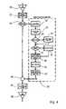
- FIG. 8illustrates a flow diagram of a DSP pipeline provided with an error correction test.
- Much of FIG. 8corresponds to earlier FIG. 4 .
- elements 20 - 24 and 46 - 50correspond to the same numbered elements in FIG. 4 and will not be discussed further.
- a sampled value a of a defect pixelis retrieve from the captured image and provided to both the defect correction algorithm in block 50 (as discussed with respect to FIG. 4 ) and to the correlation test in block 54 .
- the defect correction algorithm in block 50provides an interpolated defect value as an estimated value â to the correlation test in block 54 .
- Block 54execute a correlation test on the two received quantities as discussed above with respect to FIGS.
- interpolated defect value âis accepted, it is forwarded to mixer or accumulator block 56 that generally corresponds to block 44 in FIG. 4 . If the interpolated defect value â is not accepted, however, block 56 operates as if the original value a was good, or good enough, so that the measured value a is taken as being the best one available.
Landscapes
- Engineering & Computer Science (AREA)
- Multimedia (AREA)
- Signal Processing (AREA)
- Physics & Mathematics (AREA)
- Spectroscopy & Molecular Physics (AREA)
- Color Television Image Signal Generators (AREA)
Abstract
Description
The priority benefit of the Oct. 10, 2002 filing dates of U.S. provisional patent applications Ser. Nos. 60/417,152 and 60/417,142 are hereby claimed.
The present invention relates to a method and apparatus for adaptive pixel defect correction in a multi-color matrix based sensor arrangement through the assessing of edge continuity, a computer program and a computer program for controlling such method in a computer, and an image sensing facility encompassing such apparatus. In particular, the present invention relates to a method for adaptive pixel defect correction in a multi-color matrix-based sensor arrangement that assesses pixel values of a two-dimensional multi-pixel kernel around a particular pixel when determining an apparent defect value of said particular pixel.
Multi-color and matrix-based sensor arrangements are coming into rapidly expanding use, where the matrix size expressed in the number of pixels is increasing more or less exponentially in time, and the pixel size is generally decreasing likewise. The probability that a particular pixel will be defective is decreasing as well, but not at the same high rate, so that the overall probability for a matrix to have a defective pixel is on the rise. In many cases, such is commercially unacceptable, so there exists a growing need to provide for an algorithmic procedure that will correct as much as possible the effect of such defective pixels, while requiring only minimal memory facilities and power consumption, needing to access only a small number of image lines/columns at a time, and being applicable to various different defect categories whilst being independent of other DSP (=Digital Signal Processing)-based algorithms, such as those for removing false colors, overall influencing of hue or luminance, or others. The fields of application of such CCD (=Charged Coupled Device), CMOS (=Complementary Metal Oxide Semiconductor), and similarly organized sensors are digital still cameras, digital cinematography, video cameras, scientific imaging, broadcast cameras, surveillance, security monitoring, and various others.
By itself, United States Patent Publication 2002/0015111 to Harada and published on Feb. 7, 2002 discloses an image processing apparatus and associated method. In contradistinction with the present invention, Harada uses a two-dimensional adaptive interpolation wherein a hard decision is made to select the pixels that will be averaged for finding the defective pixel. Moreover, no correlations across different color planes are used, so that the reference is based on a different perceptual model from the present invention.
In consequence, amongst other things, it is an object of the present invention to introduce the cross-correlation between different color planes as a perceptually-based mechanism for correcting defective pixels.
This an other objects are achieved in a method of adaptive pixel correction of a multi-color matrix from a sensor that includes collecting pixel values, generating plural vectors, normalizing values and determining an estimated value. The collecting pixel values collects values of a two-dimensional multi-pixel kernel around a particular pixel from the multi-color matrix. The generating plural vectors generates vectors from the kernel where each vector has the particular pixel as a central element. The normalizing values normalizes values for nearest neighbor elements to the central element for each vector. The determining an estimated value determines the value based on the normalized values.
This an other objects are also achieved in a system for adaptive pixel correction of a multi-color matrix from a sensor comprising a processor and first, second, third and fourth modules. The first module controls the processor to collect pixel values of a two-dimensional multi-pixel kernel around a particular pixel from the multi-color matrix. The second module controls the processor to generate plural vectors from the kernel where each vector has the particular pixel as a central element. The third module controls the processor to normalizing values for nearest neighbor elements to the central element for each vector. The fourth module controls the processor to determine an estimated value based on the normalized values.
This an other objects are also achieved in a computer readable medium to control a processor for adaptive pixel correction of a multi-color matrix from a sensor. The medium includes first, second, third and fourth modules. The first module controls the processor to collect pixel values of a two-dimensional multi-pixel kernel around a particular pixel from the multi-color matrix. The second module controls the processor to generate plural vectors from the kernel where each vector has the particular pixel as a central element. The third module controls the processor to normalizing values for nearest neighbor elements to the central element for each vector. The fourth module controls the processor to determine an estimated value based on the normalized values.
The invention will be described in detail in the following description of preferred embodiments with reference to the following figures wherein:
A co-pending patent application by the present inventor, titled “Method For Reconstruction Of Pixel Color Values,” filed Sep. 10, 2003, Ser. No. 10/658,413, and assigned to the same assignee as the present application, relates to object-based color reconstruction and is incorporated herein by reference. The reconstruction of color pixel values is based on soft decisions in the various color planes, and in particular, by taking into account the spatial response of the human visual system. The results of the present invention may be applied as input to the co-pending application's invention, but such represents no express restriction.
The present invention minimizes perceptual error, utilizes pictorial properties to make intelligent solutions when correcting defective points, and can correct a wide range of shapes and sizes of a defect. Such defects may have the form of single pixels or small clusters. For situations as CCD, the defects may include a whole column or a relatively substantial part thereof. These defects have relatively high spatial frequencies and will often be prominently visible to a user or observer and therefore be unacceptable.
The present invention is, inter alia, based on recognizing the perceptual relevance of a user's expectation that edges which are present in the sensed image will generally be continuous, and that disturbance or interruption of such edges will often be due to disturbances of the sensor per se.
The property of pictorial image R-G-B correlation can be demonstrated by taking the gradient of each R, G, B image component and by analyzing where the gradients differ. In an input image a[m,n,λ] that is a function of spatial m (horizontal), n (vertical) and R-G-B components (λ), the overall gradient may be defined as
∇a=m∂a/∂xÖ+n∂a/∂y+λ∂a/∂z.
where m, n and λ are unit vectors.
∇a=m∂a/∂xÖ+n∂a/∂y+λ∂a/∂z.
where m, n and λ are unit vectors.
In a given pictorial image, it generally holds that the R-G-B values are correlated within objects and along edges. This means that the rates of change of R, G, and B are substantially constant for a point in regions with low spatial frequency and also substantially constant along the edge direction in regions with high spatial frequency. Now ideally, one would like to find the edge direction and utilize the two neighboring pixels in that direction to estimate the defect pixel a[m0,n0]. However, in a Bayer matrix arrangement each non-Green pixel is exclusively surrounded by pixels of different colors. For Green pixels, four diagonal neighbors are Green indeed, but the other four neighbors are still non-Green. However, the R-G-B colors of an image are locally correlated to each other even across the color differences. Therefore, although neighboring pixels may sample different colors, according to the invention they are still correlated to the defect pixel's color plane.
The cross-color approach represents a particularly advantageous refinement. The above is exploited by calculating the gradient of the non-defect color plane on each side for each edge direction and by applying this gradient to the nearest known pixel of the same color as the defect on each side of the defect for each edge direction. We then correlate the nearest pixels to the defect pixel's color and acquire the nearest known data. Finally, we may select the edge direction by merely determining which two neighboring pixels of a given edge direction have the least difference in magnitude, once correlated to the defect pixel's color. In a relatively simplistic implementation, the defect value may be calculated as the arithmetic mean of those two pixels. However, a fuller realization of the invention entails to calculate the weighted sum of all neighboring pixels with their weights based on their alignment with the true edge direction.
In an embodiment of the invention, a method exploits this cross-color approach to interpolating a defective pixel. The invention also relates to a computer program having program instructions for controlling a computer to implement a method that exploits this cross-color approach to interpolating a defective pixel, and to such computer program realized as a computer readable medium represented within a tangible read-only computer memory medium or being carried by an electrical signal. The invention also relates to an apparatus arranged for implementing a method that exploits this cross-color approach to interpolating a defective pixel and to an image sensing facility comprising such an apparatus. Further advantageous aspects of the invention are discussed herein.
Hereinafter, the principles of the preferred embodiment will be discussed. The sampled input image a[m,n] of M columns and N rows in total lets each image point in sequence be tested against the defect map. Finding a defect will initiate the correction thereof. The defect proper will often be signaled by a defect map detection or a defect detection apparatus. Such is state of the art.
Subsequently to the finding of a defect map, the algorithm of adaptive pixel correction of a multi-color matrix from a sensor includes the following.
Pixel values from the multi-color matrix a[m,n] are input to the algorithm column by column within a row and then advancing one row after the last column is input, and the column by column input for the row is repeated (seeFIG. 2 ). In the example discussed herein, 7 rows are buffered locally in order to process a 7×7 matrix kernel. A particular pixel, designated to be at m0, n0, is a pixel 4 columns behind and 4 rows behind the current pixel input. This particular pixel is the pixel under attention. Pixel values of a two-dimensional multi-pixel kernel around the particular pixel are extracted from the multi-color matrix to form a 7×7 matrix kernel with the particular pixel being central to the kernel. The intended color of the central pixel is assessed. The eight nearest neighbor pixels to the particular pixel form parts of four directional “vectors.” Each directional vector includes 7 pixels disposed in a straight line that passes through one nearest neighbor pixel, then through the particular pixel, and then through another nearest neighbor pixel.
In the 7×7 matrix kernel, the four directional “vectors” are derived at respective angles that differ by 45°, and which vectors are centered at the particular pixel. The central pixel is under attention, is located at m0, n0and has a value of a[m0, n0]. The four vectors have seven elements each, where each element is indexed by nn which may vary over a range from −3 to +3. The directional four vectors are extracted from the 7×7 matrix kernel so that the vector element index, denoted nn, in each vector is 0 at m0, n0and the value of all vectors at nn=0 is
di[nn=0]=a[m0,n0]
for all vectors, i=1 to 4. The four vectors are defined by:
d1[nn=−3 to +3]={a[m0,n−3] . . . a[m0,n0] . . . a[m0,n+3]};
d2[nn=−3 to +3]={a[m−3,n3] . . . a[m0,n0] . . . a[m+3,n−3]};
d3[nn=−3 to +3]={a[m3,n0] . . . a[m0,n0] . . . a[m+3,n0]}; and
d4[nn=−3 to +3]={a[m−3,n−3] . . . a[m0,n0] . . . a[m+3,n+3]}.
If the defect map indicates a column is defective at the central image point, the vertical vector in question is thereupon ignored, thus reducing the number of vectors to process from four to three. This generally is only relevant for a CCD sensor.
Next, all active vectors are checked for uncorrected error element. Uncorrected error elements in vectors are elements corresponding to pixels in the multi-color matrix from the sensor that are marked as defective. Because all defects are corrected in a column by column then row by row sequence, defects in pixels that have been processed previously should have been corrected already, but defects in pixels that have yet to be processed may have an uncorrected error. Such uncorrected error pixels in the kernel (elements in the vectors) are in addition to the particular pixel under attention (i.e., the defect point herein) that is located at m0, n0. For example, from the 7×7 matrix kernel surrounding the particular pixel under attention, the vector d1[nn=−3 to +3] is extracted, and this directional vector has values {a[m0, n−3] . . . a[m0, n0] . . . a[m0, n+3]}. The values of the vector elements for the index range nn=−3 to −1 have already been processed (seeFIG. 2 ), the value for the vector element for index nn=0 is the particular pixel under attention (i.e., the defect point herein), and the values for the vector elements for the index range nn=+1 to +3 have yet to be determined and could still have uncorrected errors at an index that may vary fromnn defect1 to 3. If a defect exists in one of the vectors (i.e., in addition to a defect at nn=0), then the element corresponding to the defect will be interpolated locally within the vector on the same side of the central element (i.e., the same side of nn=0). The interpolation depends on the vector to ensure that a step function on one side of the vector will not be averaged into the other side. The vector itself will therefore not be later falsely considered as the edge itself. A vector with an uncorrected error element is processes as follows:
ifnndefect=+3, di[nndefect]=di[nndefect−2],
ifnndefect=+1, di[nndefect]=di[nndefect+2], and
otherwise,di[nndefect]=di[nndefect].
In this way the uncorrected error element at nndefectis “filled in” with a value so that a value can be estimated for the particular pixel under attention (i.e., the defect point herein) that is located at m0, n0.
Next, vector elements corresponding to pixels nearest to the pixel under attention at m0, n0(i.e., the values at di[nn=−1] and di[nn=+1]) are normalized to the color plane of the defect. Normalization is accomplished by calculating the gradient of the non-defect color plane on each side of di[0] and by applying the gradient to the nearest sampled elements di[−2] and di[+2] of the same color plane as the particular pixel under attention. The procedure is carried out as follows for each vector di.
The gradients of the non-defect color plane on either side of the particular pixel are calculated for each vector according to:
∇1[−1]={di[−1]−di[−3]}/2, and
∇i[+1]={di[+1]−di[+3]}/2.
where ∇i[−1] and ∇i[+1] are the single-sided single-color gradients on the minus and plus side of the particular pixel under attention, respectively.
∇1[−1]={di[−1]−di[−3]}/2, and
∇i[+1]={di[+1]−di[+3]}/2.
where ∇i[−1] and ∇i[+1] are the single-sided single-color gradients on the minus and plus side of the particular pixel under attention, respectively.
Then theses gradients from the non-defect color plane are correlated to the pixels in the defect color plane that are nearest to the particular pixel under attention. This is accomplished by defining new vector elements to estimate the nearest sample elements in the defect color plane to the particular pixel under attention. Let the normalized vector elements be given by:
i[−1]=di[−2]+∇i[−1], and
i[+1]=di[+2]+∇i[+1].
wherei[−1] andi[+1] are the single-sided normalized vector elements on the minus and plus side of the particular pixel under attention, respectively.

where
Then, for vectors for which normalized vector elements were found, we substitute the normalized vector elements for the values at di[nn=−1] and di[nn=+1] in the color plane of the defect as follows:
di[−1]=i[−1], anddi[+1]=i[+1].
di[−1]=
The nearest sampled elements of the same color plane as the particular pixel under attention are sample measurement found at di[−2] and di[+2]. The single-sided normalized vector elementsi[−1] andi[+1] are estimates of samples of the same color as the particular pixel under attention that could have been made at di[nn=−1] and di[nn=+1] if such sample measurements were made. In this way, the values of the directional vector elements from di[−2] to di[+2], omitting only di[0], have been either sampled or estimated, and the vectors can next be used to determine an edge vector.
The procedure of normalizing the non-defect color plane pixels has been illustrated inFIGS. 3 athrough3c.
Now, we determine an edge-biased weight Xithat uses the distance between nn=+1 and nn=−1. A distance value for each vector is determined to be
δi=abs val{di[−1]−di[+1]}.
Then, a measure of an alignment of direction vector i to an edge at a[m0, n0] is given by:
Xi={1−δik/(Σjδjk)}/(I−1)
where j is an index over all vectors and I is determined by the number of other vectors other than the current vector i under consideration. For example, when there are four vectors numbered 1 through 4 and the current vector under consideration is i equals 2, then I is 3 (i.e., 4 minus 1).
Herein, the parameter k can be adjusted to modify the algorithm's sensitivity to the differences in di[nn], where the sensitivity increases with the value of the exponent k. The vector aligned closest to the edge direction (i.e., the minimum value of the absolute difference) would have the maximum value of Xi. Let this edge vector be symbolized by di→[nn]. InFIG. 3 c, this step of finding a weighted measure for the edge direction is indicated by the arrow.
Finally, the particular pixel under attention a[m0, n0] is estimated using the weight factors Xito yield the estimation:
â=ΣiXi{(di[−1]+di[+1])/2}.
â=ΣiXi{(di[−1]+di[+1])/2}.
Up to now, no relation has been considered between the defect's value and the actual scene. The inventor has however recognized that it is possible to check the quality of the estimations. In fact, the algorithm is evaluated on the basis of the human visual system and the Nyquist theorem. Often, a defect value will be acceptable in high-frequency regions because the visual system's differentiation ability changes with spatial frequency. Now, the above defect correction algorithm attempts to estimate a defective pixel. According to Nyquist, the highest non-aliased frequency (the Nyquist frequency fN) that the Red, Green, and Blue pixels may sample is equal to half the maximum frequency they may record in a particular direction. The highest recordable unalised frequency is at a minimum V2of a cycle per pixel (i.e., the full period is 2 pixels long) in a given sample color plane. In a Bayer pattern, red for example, is sampled every two pixels, and the Nyquist frequency would be ¼ of a cycle per pixel (i.e., the full period is 4 pixels long). Moreover, the occurrence of a defective pixel will further lower the Nyquist frequency by half such that the maximum recordable non-aliased frequency would be ⅛ cycle per pixel (i.e., a full period is 8 pixels long).
Now, we start by assuming that the CFA (i.e., color filter array) has a minimum sampling rate of ¼ cycle per pixel (i.e., the full period is 4 pixels long). The correlation is done through using gradients measured at a two-pixel spacing and so could result in a zero gradient through aliasing: then it would be impossible to correlate the non-defect colors. This could lead to a 100% deviation error. On the other hand, if the defect pixel itself deviates only by 10%, using it uncorrected would have been better. Therefore, the typical magnitude of a pixel's defect may be used to decide whether the corrected or rather the uncorrected value of the pixel is a better approximation.
When spatial image frequencies surpass the Nyquist frequency, the correction could be unacceptable. In fact, in such high frequency regions many errors would be perceptually acceptably anyway. On the other hand, in regions with low spatial frequency the requirements set by a user are quite a lot higher; but advantageously, in such a case, the algorithm is much less prone to aliasing. Therefore, if the calculated error is greater than the a predetermined error, it would be better to only correct for the latter.
ε=abs val{amax−a′}/C
where amaxis the maximum possible deviation that the defective pixel is capable of.
Rejecting all larger deviations (i.e., larger than εC) would discard solutions where the error is less than the error in the value of a(m, n) for certain frequencies. However, in a single-defect case, the Nyquist frequency is ⅛ cycle per pixel. InFIG. 3 , a Red pixel is defective, so that the Red pixels are locally sampled only every four pixels. The maximum recordable frequency is ¼ cycle per pixel, and the Nyquist frequency fNis ½ of that. Since the adaptive edge algorithm uses gradients to calculate an estimate of the pixel value for the defect pixel, the maximum non-aliased signal would be ⅛. When the defect pixel occurs at a local maximum such as inFIG. 5 , the correction will over-estimate the value for the defect pixel, although it can never exceed C/16.
Although the error would not exceed fNC, no system will have a perfect Modulation Transfer Function MTF in practice. The MTF may be either theoretically computed or actually measured. The formal aliasing tolerance value t may therefore be given by t=fN·MTF(fN). This tolerance value t is added to the maximum defect deviation value ε. Since the aliasing tolerance value t is a function of the local Nyquist frequency times the MTF at that frequency, the combined maximum defect deviation value and aliasing tolerance value is also a function of the local Nyquist frequency. The formal definition of the correction test may be expressed as follows:
if abs val{â−a}≦(εC+tC)
then, a[m0,n0]=â,
otherwise, a[m0,n0]=a.
if abs val{â−a}≦(εC+tC)
then, a[m0,n0]=â,
otherwise, a[m0,n0]=a.
Having described preferred embodiments of a novel method and apparatus for adaptive pixel correction of a multi-color matrix from a sensor (which are intended to be illustrative and not limiting), it is noted that modifications and variations can be made by persons skilled in the art in light of the above teachings. It is therefore to be understood that changes may be made in the particular embodiments of the invention disclosed which are within the scope and spirit of the invention as defined by the appended claims.
Having thus described the invention with the details and particularity required by the patent laws, what is claimed and desired protected by Letters Patent is set forth in the appended claims.
Claims (31)
1. A method of adaptive pixel correction of a multi-color matrix from a sensor comprising:
collecting pixel values of a two-dimensional multi-pixel kernel around a particular pixel from the multi-color matrix;
generating plural vectors from the kernel, each vector having the particular pixel as a central element;
normalizing values for nearest neighbor elements to the central element for each vector; and
determining an estimated value for the particular pixel based on the normalized values.
2. The method ofclaim 1 , wherein the determining includes:
assessing an edge direction at the particular pixel from the normalized values; and
interpolating the estimated value for the particular pixel based on the normalized value for the edge direction.
3. The method ofclaim 1 , wherein the generating includes disregarding a vertical vector when the corresponding column has been marked as having a column defect.
4. The method ofclaim 1 , further comprising interpolating a value of a vector element corresponding to a defective pixel in the kernel other than the particular pixel.
5. The method ofclaim 4 , wherein the interpolating the value of the vector element includes:
determining whether the defective pixel exists within the kernel; and
locally interpolating the value for the vector element in a defective vector such that a step function along one half of the defective vector does not average into an opposite half of the defective vector when the defective pixel exists.
6. The method ofclaim 1 , wherein the plural vectors includes four vectors.
7. The method ofclaim 1 , wherein the multi-color matrix is a Bayer matrix.
8. The method ofclaim 1 , wherein the kernel occupies a square that is symmetrically centered around the particular pixel.
9. The method ofclaim 8 , wherein the kernel includes 7 by 7 pixels.
10. The method ofclaim 1 , wherein the normalizing includes:
assessing an intended color of the particular pixel;
finding first and second single-sided single-color gradients for each vector, each gradient being a difference of values from a non-defect color plane along a corresponding vector; and
combining the single-sided single-color gradient with a value of a corresponding pixel of the intended color of the corresponding vector to define a new value for a nearest neighbor pixel to the particular pixel.
11. The method ofclaim 1 , wherein the determining the estimated value includes:
assessing an edge direction at the particular pixel from the normalized values by determining an edge biased weight quantity according to
X1={1−δik/(Σiδik)}/(I−1),
X1={1−δik/(Σiδik)}/(I−1),
for each vector i wherein δi=abs val{di[−1]−di[+1]} and selecting the largest absolute value of Xi; and
interpolating the estimated value for the particular pixel based on the normalized values for nearest neighbor elements and the edge direction and re-estimating a value for the particular pixel based on the selected edge biased weight quantity.
12. The method ofclaim 1 , further including repeating the method so that the kernel traverses the matrix column by column whilst at the end of each column stepping by one row.
13. The method ofclaim 1 , further including replacing the estimated value of the particular pixel with a sampled value of the particular pixel when the absolute value of a difference between the estimated value and the sampled value is greater than εC, wherein ε is a defined maximum defect deviation and C is an available dynamic range.
14. The method ofclaim 13 , wherein the defined maximum defect deviation ε is determined over a training set of pixels to be
ε=abs val{amax−a′}/C
ε=abs val{amax−a′}/C
wherein amaxis the maximum possible deviation that the defective pixel is capable of and a′ is a true value for the pixel in the training set.
15. The method ofclaim 1 , further including replacing the estimated value of the particular pixel with a sampled value of the particular pixel when the absolute value of a difference between the estimated value and the sampled value is greater than εC+tC, wherein ε is a defined maximum defect deviation, t is a tolerance value dependent on a local Nyquist frequency and C is an available dynamic range.
16. The method ofclaim 15 , wherein the defined maximum defect deviation ε is determined over a training set of pixels to be
ε=abs val{amax−a′}/C
ε=abs val{amax−a′}/C
wherein amaxis the maximum possible deviation that the defective pixel is capable of and a′ is a true value for the pixel in the training set.
17. The method ofclaim 1 , wherein upon non-finding of an edge, a defectiveness of the particular pixel is interpolated without being restricting to a selected edge biased weight quantity.
18. A system for adaptive pixel correction of a multi-color matrix from a sensor comprising:
a processor;
a first module to control the processor to collect pixel values of a two-dimensional multi-pixel kernel around a particular pixel from the multi-color matrix;
a second module to control the processor to generate plural vectors from the kernel, each vector having the particular pixel as a central element;
a third module to control the processor to normalizing values for nearest neighbor elements to the central element for each vector; and
a fourth module to control the processor to determine an estimated value based on the normalized values.
19. The system ofclaim 18 , wherein the fourth module includes:
logic to assess an edge direction at the particular pixel from the normalized values; and
logic to interpolate an estimated value for the particular pixel based on the normalized value for the edge direction.
20. The system ofclaim 18 , wherein the second module includes logic to disregard a vertical vector when the corresponding column has been marked as having a column defect.
21. The system ofclaim 18 , further comprising a fifth module to interpolate a value of a vector element corresponding to a defective pixel in the kernel other than the particular pixel.
22. The system ofclaim 21 , wherein the fifth module includes:
logic to determine whether the defective pixel exists within the kernel; and
logic to locally interpolate the value for the vector element in a defective vector such that a step function along one half of the defective vector does not average into an opposite half of the defective vector when the defective pixel exists.
23. The system ofclaim 18 , wherein the third module includes:
logic to assess an intended color of the particular pixel;
logic to find first and second single-sided single-color gradients for each vector, each gradient being a difference of values from a non-defect color plane along a corresponding vector; and
logic to combine the single-sided single-color gradient with a value of a corresponding pixel of the intended color of the corresponding vector to define a new value for a nearest neighbor pixel to the particular pixel.
24. The system ofclaim 18 , wherein the fourth module includes:
logic to assess an edge direction at the particular pixel from the normalized values by determining an edge biased weight quantity according to
Xi={1−δik/(Σiδik)}/(I−1),
Xi={1−δik/(Σiδik)}/(I−1),
for each vector i wherein δi=abs val{di[−1]−di[+1]} and selecting the largest absolute value of Xi; and
logic to interpolate the estimated value for the particular pixel based on the normalized values for nearest neighbor elements and the edge direction and re-estimating a value for the particular pixel based on the selected edge biased weight quantity.
25. A computer readable medium to control a processor for adaptive pixel correction of a multi-color matrix from a sensor, the medium comprising:
a first module to control the processor to collect pixel values of a two-dimensional multi-pixel kernel around a particular pixel from the multi-color matrix;
a second module to control the processor to generate plural vectors from the kernel, each vector having the particular pixel as a central element;
a third module to control the processor to normalizing values for nearest neighbor elements to the central element for each vector; and
a fourth module to control the processor to determine an estimated value based on the normalized values.
26. The medium ofclaim 25 , wherein the fourth module includes:
logic to assess an edge direction at the particular pixel from the normalized values; and
logic to interpolate an estimated value for the particular pixel based on the normalized value for the edge direction.
27. The medium ofclaim 25 , wherein the second module includes logic to disregard a vertical vector when the corresponding column has been marked as having a column defect.
28. The medium ofclaim 25 , further comprising a fifth module to interpolate a value of a vector element corresponding to a defective pixel in the kernel other than the particular pixel.
29. The medium ofclaim 28 , wherein the fifth module includes:
logic to determine whether the defective pixel exists within the kernel; and
logic to locally interpolate the value for the vector element in a defective vector such that a step function along one half of the defective vector does not average into an opposite half of the defective vector when the defective pixel exists.
30. The medium ofclaim 25 , wherein the third module includes:
logic to assess an intended color of the particular pixel;
logic to find first and second single-sided single-color gradients for each vector, each gradient being a difference of values from a non-defect color plane along a corresponding vector; and
logic to combine the single-sided single-color gradient with a value of a corresponding pixel of the intended color of the corresponding vector to define a new value for a nearest neighbor pixel to the particular pixel.
31. The medium ofclaim 25 , wherein the fourth module includes:
logic to assess an edge direction at the particular pixel from the normalized values by determining an edge biased weight quantity according to
Xi={1−δik/(Σiδik)}/(I−1),
Xi={1−δik/(Σiδik)}/(I−1),
for each vector i wherein δi=abs val{di[−1]−di[+1]} and selecting the largest absolute value of Xi; and
logic to interpolate the estimated value for the particular pixel based on the normalized values for nearest neighbor elements and the edge direction and re-estimating a value for the particular pixel based on the selected edge biased weight quantity.
Priority Applications (1)
| Application Number | Priority Date | Filing Date | Title |
|---|---|---|---|
| US10/658,523US7477781B1 (en) | 2002-10-10 | 2003-09-10 | Method and apparatus for adaptive pixel correction of multi-color matrix |
Applications Claiming Priority (3)
| Application Number | Priority Date | Filing Date | Title |
|---|---|---|---|
| US41715202P | 2002-10-10 | 2002-10-10 | |
| US41714202P | 2002-10-10 | 2002-10-10 | |
| US10/658,523US7477781B1 (en) | 2002-10-10 | 2003-09-10 | Method and apparatus for adaptive pixel correction of multi-color matrix |
Publications (1)
| Publication Number | Publication Date |
|---|---|
| US7477781B1true US7477781B1 (en) | 2009-01-13 |
Family
ID=40223929
Family Applications (2)
| Application Number | Title | Priority Date | Filing Date |
|---|---|---|---|
| US10/658,523Active2027-07-20US7477781B1 (en) | 2002-10-10 | 2003-09-10 | Method and apparatus for adaptive pixel correction of multi-color matrix |
| US12/386,779AbandonedUS20090263017A1 (en) | 2002-10-10 | 2009-04-23 | Method for reconstruction of pixel color values |
Family Applications After (1)
| Application Number | Title | Priority Date | Filing Date |
|---|---|---|---|
| US12/386,779AbandonedUS20090263017A1 (en) | 2002-10-10 | 2009-04-23 | Method for reconstruction of pixel color values |
Country Status (1)
| Country | Link |
|---|---|
| US (2) | US7477781B1 (en) |
Cited By (11)
| Publication number | Priority date | Publication date | Assignee | Title |
|---|---|---|---|---|
| US20060115178A1 (en)* | 2004-11-30 | 2006-06-01 | Jian Fan | Artifact reduction in a digital video |
| US20080273102A1 (en)* | 2007-05-01 | 2008-11-06 | Hoya Corporation | Detection device for defective pixel in photographic device |
| US20080291319A1 (en)* | 2007-04-11 | 2008-11-27 | Red.Com, Inc. | Video camera |
| US20090052769A1 (en)* | 2007-08-23 | 2009-02-26 | Samsung Electronics Co., Ltd. | Method and apparatus for correcting chromatic aberration of image |
| US20100013963A1 (en)* | 2007-04-11 | 2010-01-21 | Red.Com, Inc. | Video camera |
| WO2013022113A1 (en)* | 2011-08-09 | 2013-02-14 | Canon Kabushiki Kaisha | Image processing apparatus and control method therefor |
| US20130051665A1 (en)* | 2011-08-31 | 2013-02-28 | Hirotaka SHINOZAKI | Image processing apparatus, image processing method, and program |
| US20140375850A1 (en)* | 2013-06-21 | 2014-12-25 | Himax Imaging Limited | System and method of reducing noise |
| US20150170376A1 (en)* | 2013-12-18 | 2015-06-18 | Imagination Technologies Limited | Defective Pixel Fixing |
| US9521384B2 (en) | 2013-02-14 | 2016-12-13 | Red.Com, Inc. | Green average subtraction in image data |
| US11503294B2 (en) | 2017-07-05 | 2022-11-15 | Red.Com, Llc | Video image data processing in electronic devices |
Families Citing this family (71)
| Publication number | Priority date | Publication date | Assignee | Title |
|---|---|---|---|---|
| KR100780932B1 (en)* | 2006-05-30 | 2007-11-30 | 엠텍비젼 주식회사 | Color interpolation method and device |
| US11792538B2 (en) | 2008-05-20 | 2023-10-17 | Adeia Imaging Llc | Capturing and processing of images including occlusions focused on an image sensor by a lens stack array |
| US8866920B2 (en)* | 2008-05-20 | 2014-10-21 | Pelican Imaging Corporation | Capturing and processing of images using monolithic camera array with heterogeneous imagers |
| DK3876510T3 (en) | 2008-05-20 | 2024-11-11 | Adeia Imaging Llc | CAPTURE AND PROCESSING OF IMAGES USING MONOLITHIC CAMERA ARRAY WITH HETEROGENEOUS IMAGES |
| JP4960309B2 (en)* | 2008-06-17 | 2012-06-27 | 株式会社東芝 | Solid-state imaging device |
| EP2502115A4 (en) | 2009-11-20 | 2013-11-06 | Pelican Imaging Corp | CAPTURE AND IMAGE PROCESSING USING A MONOLITHIC CAMERAS NETWORK EQUIPPED WITH HETEROGENEOUS IMAGERS |
| US8928793B2 (en) | 2010-05-12 | 2015-01-06 | Pelican Imaging Corporation | Imager array interfaces |
| US8929651B2 (en) | 2010-11-16 | 2015-01-06 | Thomson Licensing | System and method for the repair of anomalies in images |
| US8878950B2 (en) | 2010-12-14 | 2014-11-04 | Pelican Imaging Corporation | Systems and methods for synthesizing high resolution images using super-resolution processes |
| JP2012209709A (en)* | 2011-03-29 | 2012-10-25 | Sony Corp | Image processing apparatus and method, recording medium, and program |
| EP2708019B1 (en) | 2011-05-11 | 2019-10-16 | FotoNation Limited | Systems and methods for transmitting and receiving array camera image data |
| US20130265459A1 (en) | 2011-06-28 | 2013-10-10 | Pelican Imaging Corporation | Optical arrangements for use with an array camera |
| KR20140045458A (en) | 2011-06-28 | 2014-04-16 | 펠리칸 이매징 코포레이션 | Optical arrangements for use with an array camera |
| JP2013066146A (en)* | 2011-08-31 | 2013-04-11 | Sony Corp | Image processing device, image processing method, and program |
| US20130070060A1 (en) | 2011-09-19 | 2013-03-21 | Pelican Imaging Corporation | Systems and methods for determining depth from multiple views of a scene that include aliasing using hypothesized fusion |
| CN104081414B (en) | 2011-09-28 | 2017-08-01 | Fotonation开曼有限公司 | Systems and methods for encoding and decoding light field image files |
| EP2817955B1 (en) | 2012-02-21 | 2018-04-11 | FotoNation Cayman Limited | Systems and methods for the manipulation of captured light field image data |
| US9210392B2 (en) | 2012-05-01 | 2015-12-08 | Pelican Imaging Coporation | Camera modules patterned with pi filter groups |
| US9077943B2 (en) | 2012-05-31 | 2015-07-07 | Apple Inc. | Local image statistics collection |
| JP2015534734A (en) | 2012-06-28 | 2015-12-03 | ペリカン イメージング コーポレイション | System and method for detecting defective camera arrays, optical arrays, and sensors |
| US20140002674A1 (en) | 2012-06-30 | 2014-01-02 | Pelican Imaging Corporation | Systems and Methods for Manufacturing Camera Modules Using Active Alignment of Lens Stack Arrays and Sensors |
| PL4296963T3 (en) | 2012-08-21 | 2025-04-28 | Adeia Imaging Llc | Method for depth detection in images captured using array cameras |
| WO2014032020A2 (en) | 2012-08-23 | 2014-02-27 | Pelican Imaging Corporation | Feature based high resolution motion estimation from low resolution images captured using an array source |
| US9214013B2 (en) | 2012-09-14 | 2015-12-15 | Pelican Imaging Corporation | Systems and methods for correcting user identified artifacts in light field images |
| EP4307659A1 (en) | 2012-09-28 | 2024-01-17 | Adeia Imaging LLC | Generating images from light fields utilizing virtual viewpoints |
| WO2014078443A1 (en) | 2012-11-13 | 2014-05-22 | Pelican Imaging Corporation | Systems and methods for array camera focal plane control |
| US9462164B2 (en) | 2013-02-21 | 2016-10-04 | Pelican Imaging Corporation | Systems and methods for generating compressed light field representation data using captured light fields, array geometry, and parallax information |
| US9374512B2 (en) | 2013-02-24 | 2016-06-21 | Pelican Imaging Corporation | Thin form factor computational array cameras and modular array cameras |
| US9774789B2 (en) | 2013-03-08 | 2017-09-26 | Fotonation Cayman Limited | Systems and methods for high dynamic range imaging using array cameras |
| US8866912B2 (en) | 2013-03-10 | 2014-10-21 | Pelican Imaging Corporation | System and methods for calibration of an array camera using a single captured image |
| US9521416B1 (en) | 2013-03-11 | 2016-12-13 | Kip Peli P1 Lp | Systems and methods for image data compression |
| US9124831B2 (en) | 2013-03-13 | 2015-09-01 | Pelican Imaging Corporation | System and methods for calibration of an array camera |
| WO2014165244A1 (en) | 2013-03-13 | 2014-10-09 | Pelican Imaging Corporation | Systems and methods for synthesizing images from image data captured by an array camera using restricted depth of field depth maps in which depth estimation precision varies |
| US9888194B2 (en) | 2013-03-13 | 2018-02-06 | Fotonation Cayman Limited | Array camera architecture implementing quantum film image sensors |
| US9106784B2 (en) | 2013-03-13 | 2015-08-11 | Pelican Imaging Corporation | Systems and methods for controlling aliasing in images captured by an array camera for use in super-resolution processing |
| US9578259B2 (en) | 2013-03-14 | 2017-02-21 | Fotonation Cayman Limited | Systems and methods for reducing motion blur in images or video in ultra low light with array cameras |
| WO2014153098A1 (en) | 2013-03-14 | 2014-09-25 | Pelican Imaging Corporation | Photmetric normalization in array cameras |
| US9633442B2 (en) | 2013-03-15 | 2017-04-25 | Fotonation Cayman Limited | Array cameras including an array camera module augmented with a separate camera |
| US10122993B2 (en) | 2013-03-15 | 2018-11-06 | Fotonation Limited | Autofocus system for a conventional camera that uses depth information from an array camera |
| US9445003B1 (en) | 2013-03-15 | 2016-09-13 | Pelican Imaging Corporation | Systems and methods for synthesizing high resolution images using image deconvolution based on motion and depth information |
| US9438888B2 (en) | 2013-03-15 | 2016-09-06 | Pelican Imaging Corporation | Systems and methods for stereo imaging with camera arrays |
| WO2014150856A1 (en) | 2013-03-15 | 2014-09-25 | Pelican Imaging Corporation | Array camera implementing quantum dot color filters |
| US9497429B2 (en) | 2013-03-15 | 2016-11-15 | Pelican Imaging Corporation | Extended color processing on pelican array cameras |
| US9898856B2 (en) | 2013-09-27 | 2018-02-20 | Fotonation Cayman Limited | Systems and methods for depth-assisted perspective distortion correction |
| US8995766B1 (en)* | 2013-09-27 | 2015-03-31 | Himax Imaging Limited | Image processing method and image processing device |
| US9264592B2 (en) | 2013-11-07 | 2016-02-16 | Pelican Imaging Corporation | Array camera modules incorporating independently aligned lens stacks |
| US10119808B2 (en) | 2013-11-18 | 2018-11-06 | Fotonation Limited | Systems and methods for estimating depth from projected texture using camera arrays |
| WO2015081279A1 (en) | 2013-11-26 | 2015-06-04 | Pelican Imaging Corporation | Array camera configurations incorporating multiple constituent array cameras |
| US10089740B2 (en) | 2014-03-07 | 2018-10-02 | Fotonation Limited | System and methods for depth regularization and semiautomatic interactive matting using RGB-D images |
| US9247117B2 (en) | 2014-04-07 | 2016-01-26 | Pelican Imaging Corporation | Systems and methods for correcting for warpage of a sensor array in an array camera module by introducing warpage into a focal plane of a lens stack array |
| US9521319B2 (en) | 2014-06-18 | 2016-12-13 | Pelican Imaging Corporation | Array cameras and array camera modules including spectral filters disposed outside of a constituent image sensor |
| JP2017531976A (en) | 2014-09-29 | 2017-10-26 | フォトネイション ケイマン リミテッド | System and method for dynamically calibrating an array camera |
| US9942474B2 (en) | 2015-04-17 | 2018-04-10 | Fotonation Cayman Limited | Systems and methods for performing high speed video capture and depth estimation using array cameras |
| US10482618B2 (en) | 2017-08-21 | 2019-11-19 | Fotonation Limited | Systems and methods for hybrid depth regularization |
| TWI638339B (en)* | 2017-11-14 | 2018-10-11 | 瑞昱半導體股份有限公司 | False color removal method |
| US11270110B2 (en) | 2019-09-17 | 2022-03-08 | Boston Polarimetrics, Inc. | Systems and methods for surface modeling using polarization cues |
| WO2021071992A1 (en) | 2019-10-07 | 2021-04-15 | Boston Polarimetrics, Inc. | Systems and methods for augmentation of sensor systems and imaging systems with polarization |
| DE112020005932T5 (en) | 2019-11-30 | 2023-01-05 | Boston Polarimetrics, Inc. | SYSTEMS AND METHODS FOR SEGMENTATION OF TRANSPARENT OBJECTS USING POLARIZATION CHARACTERISTICS |
| EP4081933A4 (en) | 2020-01-29 | 2024-03-20 | Intrinsic Innovation LLC | Systems and methods for characterizing object pose detection and measurement systems |
| US11797863B2 (en) | 2020-01-30 | 2023-10-24 | Intrinsic Innovation Llc | Systems and methods for synthesizing data for training statistical models on different imaging modalities including polarized images |
| US11953700B2 (en) | 2020-05-27 | 2024-04-09 | Intrinsic Innovation Llc | Multi-aperture polarization optical systems using beam splitters |
| US12069227B2 (en) | 2021-03-10 | 2024-08-20 | Intrinsic Innovation Llc | Multi-modal and multi-spectral stereo camera arrays |
| US12020455B2 (en) | 2021-03-10 | 2024-06-25 | Intrinsic Innovation Llc | Systems and methods for high dynamic range image reconstruction |
| US11954886B2 (en) | 2021-04-15 | 2024-04-09 | Intrinsic Innovation Llc | Systems and methods for six-degree of freedom pose estimation of deformable objects |
| US11290658B1 (en) | 2021-04-15 | 2022-03-29 | Boston Polarimetrics, Inc. | Systems and methods for camera exposure control |
| US12067746B2 (en) | 2021-05-07 | 2024-08-20 | Intrinsic Innovation Llc | Systems and methods for using computer vision to pick up small objects |
| US12175741B2 (en) | 2021-06-22 | 2024-12-24 | Intrinsic Innovation Llc | Systems and methods for a vision guided end effector |
| US12340538B2 (en) | 2021-06-25 | 2025-06-24 | Intrinsic Innovation Llc | Systems and methods for generating and using visual datasets for training computer vision models |
| US12172310B2 (en) | 2021-06-29 | 2024-12-24 | Intrinsic Innovation Llc | Systems and methods for picking objects using 3-D geometry and segmentation |
| US11689813B2 (en) | 2021-07-01 | 2023-06-27 | Intrinsic Innovation Llc | Systems and methods for high dynamic range imaging using crossed polarizers |
| US12293535B2 (en) | 2021-08-03 | 2025-05-06 | Intrinsic Innovation Llc | Systems and methods for training pose estimators in computer vision |
Citations (29)
| Publication number | Priority date | Publication date | Assignee | Title |
|---|---|---|---|---|
| US5291293A (en) | 1992-06-01 | 1994-03-01 | Eastman Kodak Company | Electronic imaging device with defect correction |
| EP0635973A1 (en) | 1993-07-23 | 1995-01-25 | Koninklijke Philips Electronics N.V. | Signal correction |
| US5596367A (en) | 1996-02-23 | 1997-01-21 | Eastman Kodak Company | Averaging green values for green photosites in electronic cameras |
| US5631703A (en) | 1996-05-29 | 1997-05-20 | Eastman Kodak Company | Particular pattern of pixels for a color filter array which is used to derive luminance and chrominance values |
| WO1997034424A2 (en) | 1996-03-14 | 1997-09-18 | Polaroid Corporation | Single sensor color camera |
| US5748803A (en) | 1995-11-22 | 1998-05-05 | Linotype-Hell Ag | Method and apparatus for image value correction in optoelectronic transducers |
| US5805217A (en) | 1996-06-14 | 1998-09-08 | Iterated Systems, Inc. | Method and system for interpolating missing picture elements in a single color component array obtained from a single color sensor |
| US5881182A (en) | 1997-05-12 | 1999-03-09 | Eastman Kodak Company | Adaptive process for removing streaks in digital images |
| US5990950A (en) | 1998-02-11 | 1999-11-23 | Iterated Systems, Inc. | Method and system for color filter array multifactor interpolation |
| US6091851A (en) | 1997-11-03 | 2000-07-18 | Intel Corporation | Efficient algorithm for color recovery from 8-bit to 24-bit color pixels |
| US6229578B1 (en) | 1997-12-08 | 2001-05-08 | Intel Corporation | Edge-detection based noise removal algorithm |
| US6236433B1 (en) | 1998-09-29 | 2001-05-22 | Intel Corporation | Scaling algorithm for efficient color representation/recovery in video |
| US6330029B1 (en) | 1998-03-17 | 2001-12-11 | Eastman Kodak Company | Particular pattern of pixels for a color filter array which is used to derive luminance and chrominance values |
| GB2364461A (en) | 2000-05-24 | 2002-01-23 | Hewlett Packard Co | Correcting defective pixels in an image |
| US20020012476A1 (en) | 2000-06-23 | 2002-01-31 | Dillen Bartholomeus Goverdina Maria Henricus | Image sensor signal defect correction |
| EP1178676A1 (en) | 2000-07-31 | 2002-02-06 | Hitachi Kokusai Electric Inc. | Method and device for detecting defective pixels of a solid-state colour image-pickup apparatus |
| US20020015111A1 (en) | 2000-06-30 | 2002-02-07 | Yoshihito Harada | Image processing apparatus and its processing method |
| US20020054219A1 (en) | 2000-06-29 | 2002-05-09 | Jaspers Cornelis Antonie Maria | Processing a sensor output signal |
| US6392699B1 (en) | 1998-03-04 | 2002-05-21 | Intel Corporation | Integrated color interpolation and color space conversion algorithm from 8-bit bayer pattern RGB color space to 12-bit YCrCb color space |
| US20020063789A1 (en) | 2000-11-30 | 2002-05-30 | Tinku Acharya | Color filter array and color interpolation algorithm |
| US6697534B1 (en)* | 1999-06-09 | 2004-02-24 | Intel Corporation | Method and apparatus for adaptively sharpening local image content of an image |
| US6823086B1 (en)* | 2000-08-29 | 2004-11-23 | Analogic Corporation | Adaptive spatial filter |
| US20040240725A1 (en)* | 2001-10-26 | 2004-12-02 | Li-Qun Xu | Method and apparatus for image matching |
| US6832009B1 (en)* | 1999-09-24 | 2004-12-14 | Zoran Corporation | Method and apparatus for improved image interpolation |
| US20050041842A1 (en)* | 2003-06-13 | 2005-02-24 | Frakes David Harold | Data reconstruction using directional interpolation techniques |
| US20050135699A1 (en)* | 2003-12-23 | 2005-06-23 | General Instrument Corporation | Directional video filters for locally adaptive spatial noise reduction |
| US7003173B2 (en)* | 2001-06-12 | 2006-02-21 | Sharp Laboratories Of America, Inc. | Filter for combined de-ringing and edge sharpening |
| US7035475B1 (en)* | 1999-06-17 | 2006-04-25 | Raytheon Company | Non-traditional adaptive non-uniformity compensation (ADNUC) system employing adaptive feedforward shunting and operating methods therefor |
| US7251361B2 (en)* | 2001-07-06 | 2007-07-31 | Corel Corporation | Automatic saturation adjustment |
Family Cites Families (27)
| Publication number | Priority date | Publication date | Assignee | Title |
|---|---|---|---|---|
| FR2623040B1 (en)* | 1987-11-09 | 1990-02-09 | France Etat | METHOD AND DEVICE FOR PROCESSING INTERLACE FRAME SCAN IMAGE SIGNALS |
| JP3110924B2 (en)* | 1993-09-30 | 2000-11-20 | キヤノン株式会社 | Image forming device |
| US5629734A (en)* | 1995-03-17 | 1997-05-13 | Eastman Kodak Company | Adaptive color plan interpolation in single sensor color electronic camera |
| US5652621A (en)* | 1996-02-23 | 1997-07-29 | Eastman Kodak Company | Adaptive color plane interpolation in single sensor color electronic camera |
| KR100200628B1 (en)* | 1996-09-30 | 1999-06-15 | 윤종용 | Image quality improvement circuit and method thereof |
| US6268939B1 (en)* | 1998-01-08 | 2001-07-31 | Xerox Corporation | Method and apparatus for correcting luminance and chrominance data in digital color images |
| US6421084B1 (en)* | 1998-03-02 | 2002-07-16 | Compaq Computer Corporation | Method for interpolating a full color image from a single sensor using multiple threshold-based gradients |
| US6847737B1 (en)* | 1998-03-13 | 2005-01-25 | University Of Houston System | Methods for performing DAF data filtering and padding |
| US6674903B1 (en)* | 1998-10-05 | 2004-01-06 | Agfa-Gevaert | Method for smoothing staircase effect in enlarged low resolution images |
| US6546117B1 (en)* | 1999-06-10 | 2003-04-08 | University Of Washington | Video object segmentation using active contour modelling with global relaxation |
| AUPQ289099A0 (en)* | 1999-09-16 | 1999-10-07 | Silverbrook Research Pty Ltd | Method and apparatus for manipulating a bayer image |
| US6487304B1 (en)* | 1999-06-16 | 2002-11-26 | Microsoft Corporation | Multi-view approach to motion and stereo |
| US6721458B1 (en)* | 2000-04-14 | 2004-04-13 | Seiko Epson Corporation | Artifact reduction using adaptive nonlinear filters |
| JP4280404B2 (en)* | 2000-09-12 | 2009-06-17 | キヤノン株式会社 | Image processing apparatus and method |
| JP4269521B2 (en)* | 2001-01-24 | 2009-05-27 | コニカミノルタビジネステクノロジーズ株式会社 | Image processing apparatus and image forming apparatus |
| US8666172B2 (en)* | 2001-03-29 | 2014-03-04 | Intel Corporation | Providing multiple symmetrical filters |
| US6798910B1 (en)* | 2001-05-17 | 2004-09-28 | The United States Of America As Represented By The Secretary Of The Air Force | Self-optimizing edge detection in blurred, high-noise images |
| US6850651B2 (en)* | 2001-07-02 | 2005-02-01 | Corel Corporation | Moiré correction in images |
| JP3762267B2 (en)* | 2001-08-08 | 2006-04-05 | キヤノン株式会社 | Image processing apparatus and method |
| US6956582B2 (en)* | 2001-08-23 | 2005-10-18 | Evans & Sutherland Computer Corporation | System and method for auto-adjusting image filtering |
| US7027637B2 (en)* | 2002-02-21 | 2006-04-11 | Siemens Corporate Research, Inc. | Adaptive threshold determination for ball grid array component modeling |
| US7231084B2 (en)* | 2002-09-27 | 2007-06-12 | Motorola, Inc. | Color data image acquistion and processing |
| EP1439715A1 (en)* | 2003-01-16 | 2004-07-21 | Dialog Semiconductor GmbH | Weighted gradient based colour interpolation for colour filter array |
| US20070292022A1 (en)* | 2003-01-16 | 2007-12-20 | Andreas Nilsson | Weighted gradient based and color corrected interpolation |
| CN100544450C (en)* | 2003-06-12 | 2009-09-23 | 株式会社尼康 | Image processing method |
| KR100607805B1 (en)* | 2004-05-06 | 2006-08-02 | 매그나칩 반도체 유한회사 | Dark condition determination method and color correction method in image sensor |
| US7590267B2 (en)* | 2005-05-31 | 2009-09-15 | Microsoft Corporation | Accelerated face detection based on prior probability of a view |
- 2003
- 2003-09-10USUS10/658,523patent/US7477781B1/enactiveActive
- 2009
- 2009-04-23USUS12/386,779patent/US20090263017A1/ennot_activeAbandoned
Patent Citations (29)
| Publication number | Priority date | Publication date | Assignee | Title |
|---|---|---|---|---|
| US5291293A (en) | 1992-06-01 | 1994-03-01 | Eastman Kodak Company | Electronic imaging device with defect correction |
| EP0635973A1 (en) | 1993-07-23 | 1995-01-25 | Koninklijke Philips Electronics N.V. | Signal correction |
| US5748803A (en) | 1995-11-22 | 1998-05-05 | Linotype-Hell Ag | Method and apparatus for image value correction in optoelectronic transducers |
| US5596367A (en) | 1996-02-23 | 1997-01-21 | Eastman Kodak Company | Averaging green values for green photosites in electronic cameras |
| WO1997034424A2 (en) | 1996-03-14 | 1997-09-18 | Polaroid Corporation | Single sensor color camera |
| US5631703A (en) | 1996-05-29 | 1997-05-20 | Eastman Kodak Company | Particular pattern of pixels for a color filter array which is used to derive luminance and chrominance values |
| US5805217A (en) | 1996-06-14 | 1998-09-08 | Iterated Systems, Inc. | Method and system for interpolating missing picture elements in a single color component array obtained from a single color sensor |
| US5881182A (en) | 1997-05-12 | 1999-03-09 | Eastman Kodak Company | Adaptive process for removing streaks in digital images |
| US6091851A (en) | 1997-11-03 | 2000-07-18 | Intel Corporation | Efficient algorithm for color recovery from 8-bit to 24-bit color pixels |
| US6229578B1 (en) | 1997-12-08 | 2001-05-08 | Intel Corporation | Edge-detection based noise removal algorithm |
| US5990950A (en) | 1998-02-11 | 1999-11-23 | Iterated Systems, Inc. | Method and system for color filter array multifactor interpolation |
| US6392699B1 (en) | 1998-03-04 | 2002-05-21 | Intel Corporation | Integrated color interpolation and color space conversion algorithm from 8-bit bayer pattern RGB color space to 12-bit YCrCb color space |
| US6330029B1 (en) | 1998-03-17 | 2001-12-11 | Eastman Kodak Company | Particular pattern of pixels for a color filter array which is used to derive luminance and chrominance values |
| US6236433B1 (en) | 1998-09-29 | 2001-05-22 | Intel Corporation | Scaling algorithm for efficient color representation/recovery in video |
| US6697534B1 (en)* | 1999-06-09 | 2004-02-24 | Intel Corporation | Method and apparatus for adaptively sharpening local image content of an image |
| US7035475B1 (en)* | 1999-06-17 | 2006-04-25 | Raytheon Company | Non-traditional adaptive non-uniformity compensation (ADNUC) system employing adaptive feedforward shunting and operating methods therefor |
| US6832009B1 (en)* | 1999-09-24 | 2004-12-14 | Zoran Corporation | Method and apparatus for improved image interpolation |
| GB2364461A (en) | 2000-05-24 | 2002-01-23 | Hewlett Packard Co | Correcting defective pixels in an image |
| US20020012476A1 (en) | 2000-06-23 | 2002-01-31 | Dillen Bartholomeus Goverdina Maria Henricus | Image sensor signal defect correction |
| US20020054219A1 (en) | 2000-06-29 | 2002-05-09 | Jaspers Cornelis Antonie Maria | Processing a sensor output signal |
| US20020015111A1 (en) | 2000-06-30 | 2002-02-07 | Yoshihito Harada | Image processing apparatus and its processing method |
| EP1178676A1 (en) | 2000-07-31 | 2002-02-06 | Hitachi Kokusai Electric Inc. | Method and device for detecting defective pixels of a solid-state colour image-pickup apparatus |
| US6823086B1 (en)* | 2000-08-29 | 2004-11-23 | Analogic Corporation | Adaptive spatial filter |
| US20020063789A1 (en) | 2000-11-30 | 2002-05-30 | Tinku Acharya | Color filter array and color interpolation algorithm |
| US7003173B2 (en)* | 2001-06-12 | 2006-02-21 | Sharp Laboratories Of America, Inc. | Filter for combined de-ringing and edge sharpening |
| US7251361B2 (en)* | 2001-07-06 | 2007-07-31 | Corel Corporation | Automatic saturation adjustment |
| US20040240725A1 (en)* | 2001-10-26 | 2004-12-02 | Li-Qun Xu | Method and apparatus for image matching |
| US20050041842A1 (en)* | 2003-06-13 | 2005-02-24 | Frakes David Harold | Data reconstruction using directional interpolation techniques |
| US20050135699A1 (en)* | 2003-12-23 | 2005-06-23 | General Instrument Corporation | Directional video filters for locally adaptive spatial noise reduction |
Cited By (38)
| Publication number | Priority date | Publication date | Assignee | Title |
|---|---|---|---|---|
| US7620241B2 (en)* | 2004-11-30 | 2009-11-17 | Hewlett-Packard Development Company, L.P. | Artifact reduction in a digital video |
| US20060115178A1 (en)* | 2004-11-30 | 2006-06-01 | Jian Fan | Artifact reduction in a digital video |
| US8237830B2 (en) | 2007-04-11 | 2012-08-07 | Red.Com, Inc. | Video camera |
| US8358357B2 (en) | 2007-04-11 | 2013-01-22 | Red.Com, Inc. | Video camera |
| US20080291319A1 (en)* | 2007-04-11 | 2008-11-27 | Red.Com, Inc. | Video camera |
| US20100013963A1 (en)* | 2007-04-11 | 2010-01-21 | Red.Com, Inc. | Video camera |
| US20100265367A1 (en)* | 2007-04-11 | 2010-10-21 | Red.Com, Inc. | Video camera |
| US7830967B1 (en) | 2007-04-11 | 2010-11-09 | Red.Com, Inc. | Video camera |
| US9245314B2 (en) | 2007-04-11 | 2016-01-26 | Red.Com, Inc. | Video camera |
| US8174560B2 (en) | 2007-04-11 | 2012-05-08 | Red.Com, Inc. | Video camera |
| US9230299B2 (en) | 2007-04-11 | 2016-01-05 | Red.Com, Inc. | Video camera |
| US9019393B2 (en) | 2007-04-11 | 2015-04-28 | Red.Com, Inc. | Video processing system and method |
| US9792672B2 (en) | 2007-04-11 | 2017-10-17 | Red.Com, Llc | Video capture devices and methods |
| US9787878B2 (en) | 2007-04-11 | 2017-10-10 | Red.Com, Llc | Video camera |
| US9596385B2 (en) | 2007-04-11 | 2017-03-14 | Red.Com, Inc. | Electronic apparatus |
| US8872933B2 (en) | 2007-04-11 | 2014-10-28 | Red.Com, Inc. | Video camera |
| US8878952B2 (en) | 2007-04-11 | 2014-11-04 | Red.Com, Inc. | Video camera |
| US9436976B2 (en) | 2007-04-11 | 2016-09-06 | Red.Com, Inc. | Video camera |
| US20080273102A1 (en)* | 2007-05-01 | 2008-11-06 | Hoya Corporation | Detection device for defective pixel in photographic device |
| US20090052769A1 (en)* | 2007-08-23 | 2009-02-26 | Samsung Electronics Co., Ltd. | Method and apparatus for correcting chromatic aberration of image |
| US8150154B2 (en)* | 2007-08-23 | 2012-04-03 | Samsung Electronics Co., Ltd. | Method and apparatus for correcting chromatic aberration of image |
| CN103733608B (en)* | 2011-08-09 | 2017-02-15 | 佳能株式会社 | Image processing apparatus and control method therefor |
| WO2013022113A1 (en)* | 2011-08-09 | 2013-02-14 | Canon Kabushiki Kaisha | Image processing apparatus and control method therefor |
| US9030579B2 (en) | 2011-08-09 | 2015-05-12 | Canon Kabushiki Kaisha | Image processing apparatus and control method that corrects a signal level of a defective pixel |
| CN103733608A (en)* | 2011-08-09 | 2014-04-16 | 佳能株式会社 | Image processing apparatus and control method therefor |
| US9582863B2 (en) | 2011-08-31 | 2017-02-28 | Sony Semiconductor Solutions Corporation | Image processing apparatus, image processing method, and program |
| US20130051665A1 (en)* | 2011-08-31 | 2013-02-28 | Hirotaka SHINOZAKI | Image processing apparatus, image processing method, and program |
| US8891866B2 (en)* | 2011-08-31 | 2014-11-18 | Sony Corporation | Image processing apparatus, image processing method, and program |
| US9716866B2 (en) | 2013-02-14 | 2017-07-25 | Red.Com, Inc. | Green image data processing |
| US9521384B2 (en) | 2013-02-14 | 2016-12-13 | Red.Com, Inc. | Green average subtraction in image data |
| US10582168B2 (en) | 2013-02-14 | 2020-03-03 | Red.Com, Llc | Green image data processing |
| US9088740B2 (en)* | 2013-06-21 | 2015-07-21 | Himax Imaging Limited | System and method of reducing noise |
| US20140375850A1 (en)* | 2013-06-21 | 2014-12-25 | Himax Imaging Limited | System and method of reducing noise |
| US9779490B2 (en)* | 2013-12-18 | 2017-10-03 | Imagination Technologies Limited | Defective pixel fixing |
| US20150170376A1 (en)* | 2013-12-18 | 2015-06-18 | Imagination Technologies Limited | Defective Pixel Fixing |
| US11503294B2 (en) | 2017-07-05 | 2022-11-15 | Red.Com, Llc | Video image data processing in electronic devices |
| US11818351B2 (en) | 2017-07-05 | 2023-11-14 | Red.Com, Llc | Video image data processing in electronic devices |
| US12301806B2 (en) | 2017-07-05 | 2025-05-13 | RED Digital Cinema, Inc. | Video image data processing in electronic devices |
Also Published As
| Publication number | Publication date |
|---|---|
| US20090263017A1 (en) | 2009-10-22 |
Similar Documents
| Publication | Publication Date | Title |
|---|---|---|
| US7477781B1 (en) | Method and apparatus for adaptive pixel correction of multi-color matrix | |
| US7499089B2 (en) | Color interpolation method in bayer array | |
| EP1401196B1 (en) | Method for detecting defective pixels in a digital image sensor | |
| US9582863B2 (en) | Image processing apparatus, image processing method, and program | |
| US7835573B2 (en) | Method and apparatus for edge adaptive color interpolation | |
| US7825965B2 (en) | Method and apparatus for interpolating missing colors in a color filter array | |
| EP1977613B1 (en) | Interpolation of panchromatic and color pixels | |
| US7995840B2 (en) | Image processing apparatus, image processing method, and program for attaining image processing | |
| US9131174B2 (en) | Image processing device, image processing method, and program for detecting and correcting defective pixel in image | |
| US8131111B2 (en) | Device of processing dead pixel | |
| US8861895B2 (en) | Image processing apparatus | |
| EP2352301A1 (en) | Image processing device, image processing method, and program | |
| JP2004080761A (en) | Digital imaging system and method for combining demosaicing and bad pixel correction | |
| US20170257584A1 (en) | Image processing device, image processing method, and image processing system | |
| KR20040066051A (en) | Weighted gradient based and color corrected interpolation | |
| KR20100078623A (en) | A color demosaicing device and a color demosaicing method | |
| CN102970463A (en) | Image processing device, image processing method and program | |
| CN110891172B (en) | Dead pixel detection and correction device | |
| US5821999A (en) | Method and system for fractally interpolating intensity values for a single color component array obtained from a single color sensor | |
| Tanbakuchi et al. | Adaptive pixel defect correction | |
| US20110069891A1 (en) | Edge detection apparatus and computing circuit employed in edge detection apparatus | |
| JP4579570B2 (en) | Shading method | |
| CN101939762A (en) | Method and device for reconstructing a color image | |
| US7433512B2 (en) | Method and apparatus for finding and correcting single-pixel noise defects in a two-dimensional camera pixel field and a camera provided with such an apparatus | |
| US20040114047A1 (en) | Method for transforming an offset sensor array |
Legal Events
| Date | Code | Title | Description |
|---|---|---|---|
| AS | Assignment | Owner name:DALSA, CORP., CANADA Free format text:ASSIGNMENT OF ASSIGNORS INTEREST;ASSIGNOR:TANBAKUCHI, ANTHONY AMIR;REEL/FRAME:014496/0380 Effective date:20030903 | |
| STCF | Information on status: patent grant | Free format text:PATENTED CASE | |
| CC | Certificate of correction | ||
| CC | Certificate of correction | ||
| FPAY | Fee payment | Year of fee payment:4 | |
| REMI | Maintenance fee reminder mailed | ||
| FPAY | Fee payment | Year of fee payment:8 | |
| SULP | Surcharge for late payment | Year of fee payment:7 | |
| AS | Assignment | Owner name:TELEDYNE DALSA, INC., CANADA Free format text:CHANGE OF NAME;ASSIGNOR:DALSA CORPORATION;REEL/FRAME:047254/0072 Effective date:20110212 | |
| AS | Assignment | Owner name:TELEDYNE DIGITAL IMAGING, INC., CANADA Free format text:MERGER;ASSIGNOR:TELEDYNE DALSA, INC.;REEL/FRAME:047908/0135 Effective date:20181231 | |
| MAFP | Maintenance fee payment | Free format text:PAYMENT OF MAINTENANCE FEE, 12TH YEAR, LARGE ENTITY (ORIGINAL EVENT CODE: M1553); ENTITY STATUS OF PATENT OWNER: LARGE ENTITY Year of fee payment:12 |