US7477710B2 - Systems and methods for analog to digital conversion with a signal cancellation system of a receiver - Google Patents
Systems and methods for analog to digital conversion with a signal cancellation system of a receiverDownload PDFInfo
- Publication number
- US7477710B2 US7477710B2US11/005,679US567904AUS7477710B2US 7477710 B2US7477710 B2US 7477710B2US 567904 AUS567904 AUS 567904AUS 7477710 B2US7477710 B2US 7477710B2
- Authority
- US
- United States
- Prior art keywords
- digital signal
- signal
- interference
- receiver
- processing
- Prior art date
- Legal status (The legal status is an assumption and is not a legal conclusion. Google has not performed a legal analysis and makes no representation as to the accuracy of the status listed.)
- Active, expires
Links
Images


Classifications
- H—ELECTRICITY
- H04—ELECTRIC COMMUNICATION TECHNIQUE
- H04B—TRANSMISSION
- H04B1/00—Details of transmission systems, not covered by a single one of groups H04B3/00 - H04B13/00; Details of transmission systems not characterised by the medium used for transmission
- H04B1/69—Spread spectrum techniques
- H04B1/707—Spread spectrum techniques using direct sequence modulation
- H04B1/7097—Interference-related aspects
- H04B1/7103—Interference-related aspects the interference being multiple access interference
- H04B1/7107—Subtractive interference cancellation
Definitions
- This inventiongenerally relates to Analog to Digital (“A/D”) conversion. More specifically, the invention relates to a plurality of A/D conversions in which at least one of the A/D conversions is operable with a signal cancellation system of a receiver.
- A/DAnalog to Digital
- Such a systemmay be particularly beneficial to communications employing Code Division Multiple Access (“CDMA”), Wideband CDMA, Broadband CDMA, (“UMTS”), Global Positioning System (“GPS”) and combinations thereof.
- CDMACode Division Multiple Access
- UMTSBroadband CDMA
- GPSGlobal Positioning System
- Interference in communicationsobstructs the intended reception of a signal and is a persistent problem. Interference may exist in many forms. In CDMA communications, for example, interference is typically the result of receiving one or more unwanted signals simultaneously with a selected signal. These unwanted signals may be similar to that of the selected signal and may therefore disrupt the reception of the selected signal. This disruption of the selected signal may corrupt data retrieval processes of a selected signal. Such problems are typical in CDMA telephony systems.
- a communications systemtypically includes a plurality of “base station” transceivers providing a coverage area within a geographic region. These base stations communicate with mobile telephones and/or other CDMA devices operating within the coverage area.
- a base stationprovides a coverage “cell” within the overall communication coverage area maintained by the communications system. While within a particular cell, a mobile telephone can communicate with the base station providing the coverage for that cell. As the mobile telephone moves to the cell of another base station, communications between the mobile telephone and the base station providing the initial cell coverage can be transferred via a “hand off” to the other base station.
- CDMA cellshave overlapping coverage.
- Each base station within a CDMA telephony systemuses coded signals to communicate with mobile telephones.
- coded signalsFor example, typical CDMA telephony systems use pseudorandom number, or pseudo-noise, (“PN”) spreading codes, occasionally referred to as “short codes,” to encode data signals. These encoded data signals are transmitted to and from mobile telephones to convey digitized voice and/or other forms of digital communication.
- PN codesare known to those skilled in the art.
- the base stationapplies a short code to the data at a rate that is faster than that of the symbol rate.
- the short codeis applied to the data such that there are multiple “chips” of the code for any given symbol of data.
- Such an application of the short codeis commonly referred to as direct sequence spreading of the data. Chips and their associated chipping rates are known to those skilled in the art.
- each base stationis assigned a particular timing offset of the short code to differentiate between base stations.
- Mobile telephonesmay therefore determine the identity of a particular base station based on the timing offset of the short code.
- the data signalsare often further encoded with a unique “covering” code.
- Such covering codesprovide “channelization” for a signal that increases the probability of data recovery of a selected signal.
- data encoded with a covering codecan further differentiate signals thereby improving detection and subsequent processing of a selected signal.
- covering codesare often used in CDMA telephony systems and typically include families of codes that are orthogonal (e.g., a Walsh code) or codes that are substantially orthogonal (e.g., a quasi-orthogonal function (“QOF”)).
- Orthogonal and substantially orthogonal covering codeshave properties that allow for the differentiation of unwanted signals and are known to those skilled in the art.
- Walsh codes and QOF codesare known to those skilled in the art.
- Both the short codes and the covering codesassist in the detection, acquisition, tracking and data recovery of a selected signal.
- interference caused by other signalsmay still degrade data recovery of the selected signal.
- a mobile telephonecommunicates with a particular base station within the coverage cell of that base station
- communication to and from other base stationscan interfere with the mobile telephone communication. Since cells often overlap one another to ensure that all desired geographic regions are included in the coverage area of the communication system, one or more signals to and from one base station may interfere with the communication link, or “channel,” between the mobile telephone and another base station. This effect is commonly referred to as cross-channel interference.
- Multipathcan create interference due to the reception of multiple copies of a selected signal at differing times.
- Multipathtypically occurs because of obstructions, such as buildings, trees, et cetera, that create multiple transmission paths for a selected signal.
- These separate transmission pathsmay have unique distances that cause the signal to arrive at a receiver at differing times and is commonly referred to as co-channel interference. Additionally, the effects of these separate paths may bleed over into other cells to cause cross-channel interference.
- Multipathcreates co-channel interference because, among other reasons, the orthogonality of the covering codes for a received signal is essentially lost due to timing offsets associated with the multipath. For example, a multipath signals arriving at a receiver at differing times cause a misalignment of the covering code. Such a misalignment can result in a high cross-correlation between covering codes and a reduction in the ability to correctly retrieve conveyed data.
- a rake receivermay have a plurality of “fingers,” wherein each finger of the rake receiver independently estimates channel gain and other signal characteristics (e.g., phase) of the selected signal to more accurately demodulate data of the selected signal and subsequently retrieve the data.
- Each fingeris assigned a particular “path” of the selected signal (i.e., one of the paths of a transmitted signal that comprises multipath signals). Additionally, as signal characteristics change, the fingers may be assigned or de-assigned to other “paths” of the signal to improve data retrieval.
- FIG. 1illustrates a block diagram of a prior art rake receiver 100 .
- Rake receiver 100is configured for receiving an analog radio signal and converting that radio signal to a digital signal in the receiver front-end 110 .
- the digital signalis subsequently processed by the rake receiver (i.e., by among other things processing fingers 104 1 . . . P , where “P” is an integer greater than one) to extract data and/or voice from the digital signal.
- the digital signalis transferred to searcher finger 103 , which detects a signal path that is subsequently assigned to a processing finger 104 for tracking and demodulation.
- Each processing finger 104is assigned a unique signal path to process the signal of interest (“SOI”) of the received signal. For example, each processing finger 104 may track a signal path that comprises a plurality of channels. The processing finger may then demodulate a particular channel for subsequent combining and processing.
- SOIsignal of interest
- Combiner 105combines the processed signals from processing fingers 104 to improve an estimate of the SOI.
- combiner 105may perform maximal ratio combining (“MRC”) of the demodulated signals produced by each of the processing fingers 104 .
- This combiningmay improve the signal quality of the SOI estimate and is subsequently processed by the rake receiver 100 to extract data and/or voice.
- Extraction of the data and/or voiceis performed by descrambler 106 , deinterleaver 107 and decoder 108 of rake receiver 100 .
- descrambler 106deinterleaver 107 and decoder 108 of rake receiver 100 .
- Such descrambling, deinterleaving and decodingis well-known to those skilled in the art.
- rake receiver 100Prior to descrambling, deinterleaving and decoding of the SOI, rake receiver 100 converts the received analog radio signal to a digital signal.
- Rake receiver 100uses a receiver front-end 110 that comprises a downconverter 101 and discretizer 102 to convert the received radio signal to a digital signal.
- Downconverter 101receives the analog radio signal, down converts that signal to a baseband signal and low pass filters the baseband signal.
- the filtered baseband signalis transferred to discretizer 102 for A/D conversion of the baseband signal and subsequent amplitude adjustment and scaling of the resultant digital signal.
- the resultant digital signalis transferred to searcher finger 103 and/or processing finger 104 for the processing described hereinabove.
- FIG. 2illustrates a block diagram of prior art rake receiver front-end 110 .
- Rake receiver front-end 110comprises down converter 101 and discretizer 102 of FIG. 1 .
- the prior art receiver front-end 110is configured for receiving an analog radio signal and down converting and discretizing that signal to a baseband digital signal.
- Down converter 101comprises baseband converter 201 and low pass filter (“LPF”) 202 .
- Baseband down converter 201receives the analog radio signal and down converts the signal to baseband as is well known to those skilled in the art. Also well-known to those skilled in the art is the subsequent low pass filtering (i.e., by LPF 202 ) of the baseband signal.
- the low pass filtered baseband signalis transferred to discretizer 102 wherein the signal is digitized by A/D converter 203 .
- the digital signalis transferred to a gain controller 204 for amplitude adjustment and scaling.
- the gain controlleris an Automatic Gain Controller (“AGC”) that receives the digital signal and automatically adjusts the amplitude of the signal based on a requisite dynamic range of the receiver.
- AGCAutomatic Gain Controller
- the amplitude adjusted signalis then transferred to a searcher finger and/or a processing finger, such as searcher finger 103 and processing finger 104 of FIG. 1 , for further processing as described hereinabove.
- A/D converters and gain controllersare well-known to those skilled in the art.
- the allocated number of bits (i.e., bit width) produced in the AGC of prior art rake receivers as a representation of the received signalis a trade-off between accuracy in data recovery and processing limitations.
- These rake receiversare typically not concerned with interference cancellation that may require an increased number of bits and as such do not produce a second digital representation of the signal with greater bit accuracy.
- the receivercomprises a discretizer configured for generating a plurality of digital signals from a received analog signal.
- the discretizermay generate two digital signals from the analog signal with each digital signal being sampled by an A/ID converter at a particular resolution. Accordingly, each of these two digital signals comprises a number of bits specific to the resolution used to generate the digital signal representations.
- Typical rake receiversuse a requisite number of bits to process a received signal. For example, once a radio signal is received by the receiver, it is digitized at a predetermined resolution. The resultant digital signal is transferred to processing fingers of the receiver for tracking and demodulation. Often, the tracking and demodulation processes of prior art receivers only requires enough information as to determine the polarity of a data symbol. The A/D conversion of the rake receiver is, therefore, performed at a resolution that can enable such a determination with consideration to the associated computational cost.
- one embodiment of the present inventionincludes a Coded Signal Processing Engine (“CSPE”) that substantially cancels the interference.
- the CSPEis communicatively coupled to the discretizer and configured for substantially canceling one or more interfering signals of a digital signal.
- the CSPEreceives a digital signal with a bit width different from the bit width used by other processing functions of the rake receiver (e.g., processing fingers and/or searcher fingers).
- the digital signal received by the CSPEis typically discretized at a higher resolution than that of the signal used by the other processing functions of the rake receiver. This higher resolution may allow for better characterization of signals that interfere with the recovery of the SOI. For example, signal cancellation as described hereinbelow may be performed using a composite interference vector (“CIV”) as described in the '015 patent application.
- the CIVincludes information regarding the amplitudes of certain interfering signals to more effectively cancel those signals.
- the CSPEincludes a matrix generator that is configured for generating an interference matrix from one or more codes of interfering signals.
- some of the interfering codesare generated by a processing finger of the rake receiver.
- the rake receivermay comprise a plurality of processing fingers, each of which is configured for processing either the digital signal used by the typical rake receiver or the substantially interference canceled digital signal generated by the CSPE.
- a processing fingermay extract a PN code of a signal assigned to the processing finger and transfer the code to the CSPE to assist in interference matrix construction.
- An example of such interference matrix constructionis also described in the '015 patent application.
- the CSPEmay generate a cancellation operator that is used to substantially cancel the one or more interfering signals from the digital signal.
- the CSPE of one embodiment of the inventionincludes a canceller that is configured for using an interference matrix and generating a cancellation operator.
- the cancellation operatoris a projection operator that projects the digital signal onto a subspace that is substantially orthogonal to a subspace of the interference.
- the CSPEmay apply the cancellation operator to the digital signal.
- Application of the cancellation operator to the digital signalsubstantially cancels the interfering signals specified in the generation of the interference matrix.
- the resultant substantially interference canceled digital signalmay have its bit representation adjusted such that it occupies the appropriate bit width for subsequent processing by a processing finger of the rake receiver.
- the CSPEmay comprise a gain controller, such as an AGC, that receives the substantially interference canceled digital signal and adjusts the energy of the signal to a bit width required by the rake receiver.
- the interference matrixis constructed using a digital signal representation of a different resolution than that used in the processing of the rake receiver.
- FIG. 1is a block diagram of a prior art rake receiver.
- FIG. 2is a block diagram of a prior art receiver front end.
- FIG. 3is a block diagram of a discretizer as utilized in one embodiment of the invention.
- FIG. 4is a rake receiver with a discretizer as utilized in one embodiment of the invention.
- FIG. 5is a block diagram of a CSPE in one embodiment of the invention.
- FIG. 6is a rake receiver with a discretizer in another embodiment of the invention.
- FIG. 7is a block diagram of a CSPE in another embodiment of the invention.
- FIG. 8is a block diagram of rake receiver in another embodiment of the invention.
- FIG. 9is a block diagram of rake receiver in another embodiment of the invention.
- FIG. 10is a flowchart of one methodical embodiment of the invention.
- FIG. 11is a block diagram of a CSPE in another embodiment of the invention.
- FIG. 3is a block diagram of discretizer 300 as used in one embodiment of the invention.
- discretizer 300comprises a pair of digital conversion chains, each comprising an A/D converter 301 (labeled A/D converter 301 1 , and 301 2 ) and an AGC 302 (labeled AGC 302 1 and 302 2 ).
- the digital conversion chains comprising A/D converter 301 1receives the baseband filtered signal produced by a down converter, such as down converter 101 of FIG. 1 , and converts the signal to a digital signal at a resolution that represents the baseband filtered signal with a first bit width M 1 .
- the resultant digital signalis then transferred to AGC 302 1 for requisite amplitude adjustment and scaling of a typical rake receiver.
- AGC 302 1may receive a digital signal comprising a first number of bits that represents the baseband filtered signal. After adjusting amplitude of the digital representation, the number of bits representing the signal may be adjusted to a second bit width N 1 to appropriately configure the signal for the requisite dynamic range of the receiver. The scaled and adjusted digital signal may then be transferred as digital signal y 1 to the searcher finger and the processing fingers of the rake receiver, such as searcher finger 103 and processing fingers 104 respectively of FIG. 1 .
- the baseband filtered signalis transferred to the digital conversion chain comprising A/D converter 301 2 and AGC 302 2 .
- the digital conversion chainconverts the baseband filtered signal to a digital signal with a different bit width.
- A/D converter 301 2may provide a different bit representation of the baseband filtered signal with a second bit width with higher resolution represented by a number of bits M 2 .
- the second bit width digital signalis then transferred to AGC 302 2 for amplitude adjustment and scaling to generate a digital signal y 2 similar to that of AGC 302 1 .
- the digital signal y 2may then be transferred to a processing engine, such as a CSPE described hereinbelow, for interference cancellation upon a signal.
- each receiver chain of the receive diversity receivermay use one or more processing engines to substantially cancel interfering signals.
- each processing enginemay be configured to receive a unique digital signal discretized to a unique bit width.
- each processing enginemay be configured to receive either or both of the digital signals y 1 and y 2 as described herein.
- discretizer 300may be implemented in software, firmware, hardware or various combinations thereof.
- Those skilled in the artare familiar with software, firmware, hardware and their various combinations and understand that such implementations are typically a matter of design choice.
- ASICApplication Specific Integrated Circuit
- FPGAField Programmable Gate Arrays
- DSPDigital Signal Processors
- other integrated circuitrye.g., custom designed circuitry.
- some aspects of the inventionmay be implemented through combinations of software using Java, C, C++, Matlab, Verilog, VHDL, and/or processor specific machine and assembly languages.
- FIG. 4is rake receiver 400 with discretizer 300 as used in one embodiment of the invention.
- discretizer 300 of FIG. 3is implemented within receiver front end 401 .
- Receiver front-end 401also comprises down converter 101 of FIG. 1 . Accordingly, receiver front-end 401 receives an analog radio signal and converts the signal to baseband for subsequent digital conversion by discretizer 300 as described above in FIG. 3 .
- the digital signal y 1is transferred to searcher finger 103 and processing fingers 104 1 . . . N .
- Processing functionality of the digital signal y 1 by searcher finger 103 and processing fingers 104 1 . . . Pis substantially the same as that described in FIG. 1 .
- searcher finger 103may detect signal paths and assign the signal paths to processing fingers 104 for processing of a SOI. Differing from FIG. 1 , however, is the introduction of digital signal y 2 by discretizer 300 .
- Discretizer 300generates the digital signal y 2 by converting the filtered baseband signal into a digital signal representation with a bit width that differs from the bit width used for signal y 1 . In one embodiment of the invention, a higher bit resolution used for digital signal y 2 is than that used for digital signal y 1 .
- the digital signal y 2is transferred to CSPE 402 wherein signal cancellation is performed thereon.
- CSPE 402receives the digital signal y 2 , as well as PN codes, chip enable (“CE”) signals and/or symbol boundary (“SB”) signals.
- the PN codes, CE signals and the SB signalsare generated by the processing fingers 104 and may be used to generate an interference matrix as described hereinabove.
- SB signalsspecify a chip location of a symbol boundary in the signal y 2 .
- CE signalsspecify a sample location of the symbol boundary and provide a reference for decimation of chip rate data.
- phase estimates of the signals assigned to processing fingers 104may also be transferred to CSPE 402 for interference matrix construction. Examples of such phase estimates are described in the '015 patent application.
- CSPE 402substantially cancels one or more interfering signals from the digital signal y 2 .
- the PN codes and/or phase estimates of interfering signalsmay be used to construct the interference matrix.
- the CE signals and the SB signalsmay be used as time reference information in the construction of the interference matrix.
- CSPE 402may then generate a cancellation operator, which is applied to the digital signal y 2 to substantially cancel the one or more interfering signals from signal y 2 and generate a substantially interference cancelled signal y 2 ′.
- the cancellation operatoris a projection operator as described hereinabove.
- CSPE 402may select either or both of the uncancelled digital signal y 2 or the substantially interference cancelled digital signal y 2 ′ for processing by one or more of processing fingers 104 1 . . . P .
- CSPE 402may selectively transfer either or both of the digital signal y 2 and the substantially interference canceled digital signal y 2 ′ to the processing fingers 404 for tracking and demodulation via an AGC in CSPE 502 .
- the AGCeffectively reduces the bitwidth of the selected signal(s) (i.e., y 2 and/or y 2 ′) to a bitwidth commensurate with the rake receiver.
- the AGCproduces the signal y 3 from the signal y 2 and signal y 3 ′ from the signal y 2 ′, respectively, where signal y 3 is substantially equivalent to y 1 .
- the demodulated signals from processing fingers 104may then be combined by combiner 105 to generate an improved estimate of an SOI.
- CSPE 402may be configured to generate a plurality of cancellation operators to substantially cancel a plurality of interfering signals.
- interference cancellationmay be performed in either a serial, a parallel or a hybrid serial/parallel manner such as described in the '777, '346 and '669 patent applications. Accordingly, the invention should only be limited by the language recited in the claims and their equivalents.
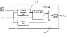
- FIG. 5is a block diagram of CSPE 402 in one embodiment of the invention.
- CSPE 402is configured for substantially canceling one or more interfering signals from digital signal y 2 .
- CSPE 402comprises S matrix generator 501 which is configured for generating an interference matrix “S” that is used to substantially cancel one or more interfering signals from the digital signal y 2 .
- matrix generator 501constructs an interference matrix from components of the one or more interfering signals.
- the generated S matrixis used to generate a cancellation operator which is applied to the digital signal y 2 to substantially cancel the interfering signals used in the matrix construction.
- CSPE 402also comprises canceller 503 which uses the generated S matrix to generate a cancellation operator for application to the digital signal y 2 .
- S matrix generator 501is configured for generating the S matrix from a PN code(s) of the interfering signal(s) and the digital signal y 2 .
- Matrix generator 501may also be configured for constructing the interference matrix from a CE signal(s), an SB signal(s) and/or phase estimate(s) of the interfering signal(s) as described above in FIG. 4 . Interference matrix construction is shown and described in greater detail in the '015 application, which is incorporated by reference.
- Canceller 503applies the cancellation operator to the digital signal y 2 , which substantially cancels or removes the interfering signal(s) specified in the S matrix from the digital signal y 2 .
- the cancellation by canceller 503results in a substantially interference canceled digital signal y 2 ′.
- the substantial cancellation of the interfering(s)may lead to an improved Signal to Noise Ratio (“SNR”) of an SOI within the digital signal y 2 since the signal energy contributions of the interfering signals are substantially removed from the overall signal energy of the digital signal y 2 .
- SNRSignal to Noise Ratio
- CSPE 402may select either the input digital signal y 2 or the substantially interference canceled digital signal y 2 ′ for transfer to AGC 504 .
- a decisionmay be made that digital signal y 2 is sufficient for processing or alternatively that the substantially interference canceled digital signal y 2 ′ would be preferable. Such a decision may be performed either by CSPE 402 or by other components within the receiver and external to CSPE 402 .
- a control signalmay be transferred to selector 505 to transfer either the selected signal to the processing finger(s) 104 of receiver 400 via AGC 504 .
- CSPE 402also comprises a delay element 502 which may compensate for delays introduced by the signal cancellation processing of S matrix generator 501 and canceller 503 .
- CSPE 402comprises AGC 504 communicatively coupled to selector 505 and configured for adjusting the amplitude of a digital signal y 2 or a substantially interference canceled digital signal y 2 ′ to a requisite amplitude and/or bit width for a receiver.
- rake receiver 400 FIG. 4may require a particular bit width for processing.
- AGC 504may adjust the amplitude and bit width of the substantially interference canceled digital signal y 2 ′ to a level commensurate with the bit widths and dynamic range of the rake receiver.
- This adjustment by AGC 504 to either the digital signal y 2 or the substantially interference canceled signal y 2 ′produces the signals y 3 and y 3 ′, respectively where the signal y 3 is substantially equivalent to the signal y 1 .
- the resulting signals y 3 and/or y 3 ′ produced by AGC 504are transferred to the processing fingers 104 and/or searcher finger 103 of FIG. 4 .
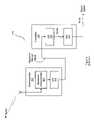
- FIG. 6is rake receiver 500 with discretizer 300 in another embodiment of the invention.
- rake receiver 500is configured substantially the same as rake receiver 400 of FIG. 4 .
- CSPE 502Differing from FIG. 4 , however, is CSPE 502 , which is configured for receiving—in addition to the digital signal y 2 —the digital signal y 1 .
- CSPE 502is still configured for generating an interference matrix S and using the interference matrix to substantially cancel one or more interfering signals from the digital signal y 2 . But, CSPE 502 generates the interference matrix S using the digital signal y 1 .
- CSPE 502receives the digital signal y 1 as well as a PN code(s) of one or more interfering signals to generate the interference matrix. Additionally, CSPE 502 may use CE signal(s) and/or SB signal(s) to assist in the generation of an interference matrix as described hereinabove. In a first embodiment, CSPE 502 uses the digital signal y 1 to generate an S matrix but perform the signal cancellation on the larger bit width digital signal y 2 . In a second embodiment, CSPE 502 uses the digital signal y 2 for both S matrix generation and the signal to which signal cancellation is performed upon. Accordingly, interference matrix construction and signal cancellation do not change significantly with respect to the matrix construction and signal cancellation performed by CSPE 402 of FIG. 5 . Examples of CSPE 502 is illustrated and described in greater detail below in FIGS. 7 and 11 .
- CSPE 502may then selectively transfer either or both of the digital signal y 1 ′ or the substantially interference canceled digital signal y 3 ′ to the processing fingers 104 for tracking and demodulation.
- the demodulated signals from processing fingers 104may then be combined by combiner 105 to generate an improved estimate of an SOI.
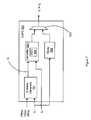
- FIG. 7is a block diagram of CSPE 502 in another embodiment of the invention.
- CSPE 502comprises S matrix generator 701 which is configured for generating an interference matrix S from digital signal y 1 as described in an embodiment of FIG. 6 .
- discretizer 300 of FIG. 3generates two digital signals y 1 and y 2 at different resolutions; thereby each signal has a different bit width.
- CSPE 502may receive each of the signals for signal cancellation purposes, wherein matrix generator 701 uses the digital signal y 1 as an input to the generation of the interference matrix S.
- Matrix construction performed by matrix generator 701is, however, substantially the same as that described in the '015 patent application.
- matrix generator 701receives a PN code(s) of one or more interfering signals for the generation of the interference matrix. Also, matrix generator 701 may receive CE signal(s), SB signal(s) and/or phase estimate(s) of the interfering signals as previously described herein.
- matrix generator 701transfers the matrix to canceller 603 .
- Canceller 603performs signal cancellation upon the digital signal y 2 by applying the cancellation operator to the signal. The signal cancellation results in a substantially interference canceled digital signal y 2 ′.
- AGCsubsequently reduces the resolution of the interference canceled digital signal y 2 ′ to produce the smaller bit width interference canceled digital signal y 3 ′.
- CSPE 502selectively transfers either the digital signal y 1 or the substantially interference canceled digital signal y 3 ′ to processing fingers, such as processing fingers 104 of FIG. 6 , via selector 505 .
- delay module 602delays the digital signal y 1 before transfer to the processing fingers, as was similarly performed in FIG. 5 .
- an additional AGCis not required after selector 505 as was required in CSPE 402 of FIG. 5 .
- FIG. 11is a block diagram of CSPE 502 in another embodiment of the invention.
- CSPE 502comprises S matrix generator 1101 which is configured for generating an interference matrix S from digital signal y 1 as described in an embodiment of FIG. 6 .
- discretizer 300 of FIG. 3generates two digital signals y 1 and y 2 at different resolutions; thereby each signal has a different bit width.
- CSPE 502may receive each of the signals for signal cancellation purposes, wherein matrix generator 1101 uses the digital signal y 2 as an input to the generation of the interference matrix S.
- Matrix construction performed by matrix generator 1101is, however, substantially the same as that described in the '015 patent application.
- matrix generator 701receives a PN code(s) of one or more interfering signals for the generation of the interference matrix. Also, matrix generator 1101 may receive CE signal(s), SB signal(s) and/or phase estimate(s) of the interfering signals as previously described herein.
- matrix generator 1101transfers the matrix to canceller 603 .
- Canceller 603performs signal cancellation upon the digital signal y 2 by applying the cancellation operator to the signal. The signal cancellation results in a substantially interference canceled digital signal y 2 ′.
- AGCsubsequently reduces the resolution of the interference canceled digital signal y 2 ′ to produce the smaller bit width interference canceled digital signal y 3 ′.
- CSPE 502selectively transfers either the digital signal y 1 or the substantially interference canceled digital signal y 3 ′ to processing fingers, such as processing fingers 104 of FIG. 6 , via selector 505 .
- delay module 602delays the digital signal y 1 before transfer to the processing fingers, as was similarly performed in FIG. 5 .
- an additional AGCis not required after selector 505 as was required in CSPE 402 of FIG. 5 . While one alternative embodiment of a CSPE has been shown and described, the invention is not intended to be limited to this alternative embodiment. Rather, the invention should only be limited by the claims and their equivalents. Additionally, those skilled in the art should readily recognize that the invention may be implemented in a variety of manners such as those employing software, hardware, firmware or various combinations thereof as described above herein.
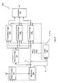
- FIG. 8is a block diagram of rake receiver 800 in another embodiment of the invention.
- rake receiverillustrates dual digital conversion chains (i.e., a first digital conversion chain comprising A/D 301 1 and AGC 301 1 and a second digital conversion chain comprising A/D 301 2 and AGC 301 2 ). These digital conversion chains operate in the same manner as discretizer 300 of FIG. 3 to generate a first digital signal y 1 at a bit width N 1 and a second digital signal y 2 at a second bit width N 2 .
- Rake receiver 800comprises a plurality of processing fingers 104 1 . . . N , each comprising a PN code generator 801 , a tracker 802 and a correlator 803 .
- the digital signal y 1is transferred from AGC 301 1 to searcher finger 103 and/or to processing fingers 104 1 . . . N as performed by a typical rake receiver.
- PN code generators 801 1. . . Ngenerate PN codes of interfering signals, which are used by trackers 802 1 . . . N to track signal paths assigned to the associated signal processing fingers 104 1 . . . N .
- trackers 802 1 . . . Ntransfer the tracked signal path information to cancellers 806 1 . . . N for interference cancellation within CSPE 805 and to delay elements 808 1 . . . N .
- interference matrix constructionis not illustrated in this embodiment. However, interference matrix construction for the purposes of this embodiment can be assumed as being performed by cancellers 806 1 . . . N .
- S matrix generation and the interference cancellation operationmay be performed with any combination of digital signals y 1 and y 2 .
- digital signal y 2may be used for the generation of the S matrix while the interference cancellation operation may be performed on digital signal y 1 .
- the digital signal y 2may be used for both S matrix generation and as the signal to which the interference cancellation operator is applied.
- trackers 802 1 . . . Nmay transfer the on-time PN codes to CSPE 805 for interference matrix construction.
- Trackers 802 1 . . . Nmay also transfer CE signals and SB signals to CSPE 805 for S matrix construction.
- cancellers 806 1 . . . Nhave AGC modules that adjust the bitwidth to N 2 as AGC 302 1 does in FIG. 3 producing the set of signals ⁇ y 3 ′ ⁇ .
- CSPE 805selectively transfers a delayed digital signal y 1 (i.e., as delayed by a delayed element 807 ) and/or one or more substantially interference canceled digital signals y 3 ′ to correlators 803 1 . . . N for subsequent demodulation.
- the delayed digital signalis y 2 that is passed through an AGC similar to AGC 302 1 as in FIG. 3 to produce an N 2 bit delayed digital signal.
- Each signal y 3 ′typically comprises an SOI with a plurality of interfering signals substantially canceled.
- Delay element 807delays the uncanceled digital signal y 1 to accommodate for delays introduced by the signal cancellation processes of cancellers 806 1 . . . N .
- delay elements 80 7operate to delay signals transferred to CSPE 805 to accommodate for delays introduced by cancellers 806 1 . . . N . These delayed signals are also transferred to correlators 803 1 . . . N for demodulation.
- the correlators 803 1 . . . Nselectively demodulate either an uncanceled signal (i.e., the delayed signal) or the signals selected by selector 101 (i.e., the substantially interference canceled signals of y 2 ′ and/or the uncanceled signal y 2 ).
- the delay elements 808 1 . . . Nmay delay the PN code(s), CE signal(s), and/or SB signal(s) in CSPE 805 .
- CSPE 805may selectively transfer one or more of the substantially interference canceled digital signals ⁇ y 3 ′ ⁇ generated by cancellers 806 1 . . . N and/or the digital signal y 1 as delayed by delay element 807 to rake receiver 800 .
- the signals that are transferred to correlators 803 1 . . . Nmay have their amplitudes adjusted to amplitudes substantially equivalent to the amplitude scaling of the RF front-end of the rake receiver 401 . Additionally, the signals may be adjusted to an appropriate bit width (i.e., dynamic range) by a gain controller of the rake receiver 800 .
- a gain controllersuch as an AGC, may be configured to the output of selector 101 or configured within cancellers 806 1 . . . N to adjust the amplitude and/or scaling of the signals transferred to correlators 803 1 . . . N . Examples of such gain controllers are illustrated and described in elements 504 of FIGS. 5 and 7 .
- the demodulated signalsare transferred from correlators 803 1 . . . N to combiner 105 to generate an improved estimate of an SOI.
- the combiner 105may combine the signals using any well-known combining method. For example, combiner 105 may combine the signals using an MRC combining.
- Rake receivers and their associated processing fingers, combiners, and various other componentsare well-known to those skilled in the art.
- the components of processing fingers, such as PN code generators 801 , trackers 802 and correlators 803are also well-known to though skilled in the art.
- FIG. 9is a block diagram of rake receiver 900 another embodiment of the invention.
- the digital signals y 1 and y 2 generated by a discretizer having two digital conversion chainsare transferred to the processing portion of rake receiver 900 and signal cancellation portion of the receiver.
- searcher finger 103receives the digital signal y 1 to detect a signal path therefrom.
- the signal y 1is transferred to processing fingers 104 1 . . . N for PN code generation by PN code generators 801 1 . . . N .
- Delay 906is introduced to the digital signal y 1 to compensate for delays introduced by CSPE 905 .
- PN code generators 801 1 . . . Ntransfer PN codes of interfering signals to CSPE 905 for S matrix construction as described hereinabove.
- the PN codesmay be used to generate interference matrices as described in the '015 patent application.
- the PN codesare masked forward to advance the PN sequences ahead by an amount substantially equivalent to the delay of cancellers 902 1 . . . N .
- This masking when applied to the PN generating sequenceadvances the PN sequence and may be used to compensate for delays introduced by cancellers 902 1 . . . N .
- interference matrix constructionis not illustrated in this embodiment for simplicity but is assumed as being performed by cancellers 902 1 . . . N on the signal y 2 for the purposes of this embodiment.
- cancellers 902 1 . . . Ngenerate cancellation operators as described hereinabove and apply those operators to the digital signal y 2 .
- Cancellers 902 1 . . . Nthereby generate a plurality of substantially interference canceled digital signals (i.e., a plurality of signals ⁇ y 3 ′ ⁇ ) wherein each signal generated by canceller typically has a unique combination of interfering signals substantially removed from the digital signal y 2 .
- An AGC modulesuch as 504 in FIG. 5 , adjusts the amplitude and bit width of each of the interference canceled digital signals y 2 ′ producing the set of interference canceled digital signals ⁇ y 3 ′ ⁇ .
- CSPE 905may selectively transfer one or more of the substantially interference canceled digital signals y 3 ′ generated by cancellers 902 1 . . . N and/or the digital signal y 1 delayed by element 906 .
- rake receiver 900may determine that signal quality of the delayed uncanceled signals being processed by processing fingers 104 is sufficient for the recovery of transmitted data. Rake receiver 900 may therefore select the delayed digital signal y 1 or processing as opposed to one of set of the substantially interference canceled digital signals ⁇ y 3 ′ ⁇ .
- the signals that are transferred to correlators 803 1 . . . Nmay have their amplitudes adjusted to requisite amplitudes of the rake receiver to exploit the full dynamic range of the available bits. Additionally, the bit width of the signals may be scaled to a requisite number of representative bits N 1 for the rake receiver 800 .
- a gain controllersuch as an AGC
- an AGCmay be configured to the output of selector 101 to adjust the amplitude and/or scaling of the signals transferred to correlators 803 1 . . . N . Examples of such gain controllers are illustrated and described in elements 504 of FIGS. 5 and 7 .
- FIG. 10is flowchart 1000 of one methodical embodiment of the invention.
- an analog signalis received in element 1001 .
- the analog signalmay be down converted to baseband and filtered as described hereinabove.
- the signalis then sampled, or digitized, at first and second resolution to respectively generate first and second digital signals in elements 1002 and 1003 .
- the first signalmay have a bit width commensurate with the number of bits used with a typical rake receiver.
- the second signalmay have a second bit width in the cancellation of interfering signals. In one embodiment of the invention the second bit width provides greater resolution than the first bit width.
- the first digital signalmay be used to generate interference codes of one or more interfering signals comprised therein, in element 1004 .
- the digital signalsmay comprise a plurality of signals such as an SOI and one or more interfering signals.
- the first digital signalmay be transferred to processing fingers of a rake receiver, which may be used to generate PN codes of the interfering signals. These interference codes may be used to substantially cancel the interfering signals from the second digital signal in element 1005 .
- the interference codesare used to generate one or more interference matrices, which are further used to respectively generate one or more cancellation operators, in element 1006 .
- the cancellation operatorsmay be projection operators that project the second digital signal onto a subspace that is substantially orthogonal to the subspace of one or more interfering signals. Such a projection operator is described in Eq. 1 hereinabove.
- the cancellation operatorsmay be applied to the second digital signal to substantially cancel interfering signals and improve SNR(s) of the SOI(s).
- the resultant substantially interference canceled digital signalsare transferred to processing fingers of a receiver, in element 1007 .
- the signalsmay be subsequently demodulated by the processing fingers, in element 1008 .
- Additional processingmay be performed by the rake receiver and may include MRC combining, descrambling, deinterleaving and/or decoding of the signals as described hereinabove.
- the embodiments described hereinmay substantially reduce interference caused by unwanted signals and improve signal processing. For example, poor signal quality due to interference may deleteriously affect acquisition, tracking and demodulation of selected signals. A reduction in interference may, therefore, result in improved signal recovery of the selected signals.
- the embodiments hereinmay advantageously require use within a CDMA telephony system. Improved processing within a CDMA telephony system may be exploited in terms of increased system capacity, transmit power reduction, increased system coverage and/or increased data rates.
- CDMACode Division Multiple Access
- WCDMAWideband CDMA
- Broadband CDMAWideband CDMA
- UMTSUniversal Mobile communications
- the above embodiments of the inventionmay be implemented in a variety of ways.
- the above embodimentsmay be implemented in software, firmware, hardware or various combinations thereof.
- Those skilled in the artare familiar with software, firmware, hardware and their various combinations.
- those skilled in the artmay choose to implement certain aspects of the invention in hardware using ASIC chips, FPGAs, DSPs and/or other integrated circuitry (e.g., custom designed circuitry).
- some aspects of the inventionmay be implemented through combinations of software using C, C++, Matlab, Verilog, VHDL and/or processor specific machine and assembly languages. Accordingly, those skilled in the art should readily recognize that such implementations are a matter of design choice and that the invention should not be limited to any particular implementation.
Landscapes
- Engineering & Computer Science (AREA)
- Computer Networks & Wireless Communication (AREA)
- Signal Processing (AREA)
- Noise Elimination (AREA)
Abstract
Description
PS⊥=I−S(STS)−1ST, (Eq. 1)
where PS⊥ is the projection operator, I is an identity matrix, S is the interference matrix and STis a transpose of S.
PS⊥=I−S(STS)−1ST, (Eq. 1)
where PS⊥ is the projection operator, I is an identity matrix, S is the interference matrix and STis a transpose of S.
PS⊥y=y−S(STS)−1STy, (Eq.2)
where PS⊥ is the projection operator, S is the interference matrix, STis a transpose of S and y is the digital signal.
Claims (48)
PS⊥=I−S(STS)−1ST,
PS⊥=I−S(STS)−1ST,
PS⊥=I−S(STS)−1ST,
PS⊥=I−S(STS)−1ST,
PS⊥=I−S(STS)−1ST,
Priority Applications (1)
| Application Number | Priority Date | Filing Date | Title |
|---|---|---|---|
| US11/005,679US7477710B2 (en) | 2004-01-23 | 2004-12-07 | Systems and methods for analog to digital conversion with a signal cancellation system of a receiver |
Applications Claiming Priority (5)
| Application Number | Priority Date | Filing Date | Title |
|---|---|---|---|
| US10/763,346US7039136B2 (en) | 2001-11-19 | 2004-01-23 | Interference cancellation in a signal |
| US10/773,777US7394879B2 (en) | 2001-11-19 | 2004-02-06 | Systems and methods for parallel signal cancellation |
| US10/935,015US7577186B2 (en) | 2002-09-20 | 2004-09-07 | Interference matrix construction |
| US10/935,669US7474690B2 (en) | 2002-11-15 | 2004-09-07 | Systems and methods for parallel signal cancellation |
| US11/005,679US7477710B2 (en) | 2004-01-23 | 2004-12-07 | Systems and methods for analog to digital conversion with a signal cancellation system of a receiver |
Related Parent Applications (4)
| Application Number | Title | Priority Date | Filing Date |
|---|---|---|---|
| US10/763,346Continuation-In-PartUS7039136B2 (en) | 2001-11-19 | 2004-01-23 | Interference cancellation in a signal |
| US10/773,777Continuation-In-PartUS7394879B2 (en) | 2001-11-19 | 2004-02-06 | Systems and methods for parallel signal cancellation |
| US10/935,669Continuation-In-PartUS7474690B2 (en) | 2002-11-15 | 2004-09-07 | Systems and methods for parallel signal cancellation |
| US10/935,015Continuation-In-PartUS7577186B2 (en) | 2002-09-20 | 2004-09-07 | Interference matrix construction |
Publications (2)
| Publication Number | Publication Date |
|---|---|
| US20050163039A1 US20050163039A1 (en) | 2005-07-28 |
| US7477710B2true US7477710B2 (en) | 2009-01-13 |
Family
ID=34799820
Family Applications (1)
| Application Number | Title | Priority Date | Filing Date |
|---|---|---|---|
| US11/005,679Active2026-04-01US7477710B2 (en) | 2004-01-23 | 2004-12-07 | Systems and methods for analog to digital conversion with a signal cancellation system of a receiver |
Country Status (1)
| Country | Link |
|---|---|
| US (1) | US7477710B2 (en) |
Cited By (7)
| Publication number | Priority date | Publication date | Assignee | Title |
|---|---|---|---|---|
| US20060227730A1 (en)* | 2005-04-07 | 2006-10-12 | Mccloud Michael L | Variable interference cancellation technology for CDMA systems |
| US20060227909A1 (en)* | 2005-04-07 | 2006-10-12 | Thomas John K | Optimal feedback weighting for soft-decision cancellers |
| US20080144748A1 (en)* | 2006-12-15 | 2008-06-19 | Samsung Electronics Co., Ltd. | Method and system for providing analog control of digital gain in a wireless device |
| US20120051473A1 (en)* | 2010-08-31 | 2012-03-01 | Andreas Mayer | Adaptive Digital Signal Processing of a Receive Signal |
| US8514910B2 (en) | 2002-09-23 | 2013-08-20 | Rambus Inc. | Systems and methods for control of receivers |
| US20140298129A1 (en)* | 2013-03-26 | 2014-10-02 | Lsi Corporation | Generating Partially Sparse Generator Matrix for a Quasi-Cyclic Low-Density Parity-Check Encoder |
| US9172456B2 (en) | 2005-04-07 | 2015-10-27 | Iii Holdings 1, Llc | Iterative interference suppressor for wireless multiple-access systems with multiple receive antennas |
Families Citing this family (3)
| Publication number | Priority date | Publication date | Assignee | Title |
|---|---|---|---|---|
| US20050169354A1 (en)* | 2004-01-23 | 2005-08-04 | Olson Eric S. | Systems and methods for searching interference canceled data |
| US7720185B2 (en)* | 2006-11-06 | 2010-05-18 | Qualcomm Incorporated | Narrow-band interference canceller |
| US9252837B1 (en)* | 2014-08-06 | 2016-02-02 | Nxp, B.V. | Split diversity data combining |
Citations (148)
| Publication number | Priority date | Publication date | Assignee | Title |
|---|---|---|---|---|
| US3742201A (en) | 1971-02-22 | 1973-06-26 | Raytheon Co | Transformer system for orthogonal digital waveforms |
| US4088955A (en) | 1975-04-07 | 1978-05-09 | Baghdady Elie J | Interference rejection technique |
| US4309769A (en) | 1980-02-25 | 1982-01-05 | Harris Corporation | Method and apparatus for processing spread spectrum signals |
| US4359738A (en) | 1974-11-25 | 1982-11-16 | The United States Of America As Represented By The Secretary Of The Navy | Clutter and multipath suppressing sidelobe canceller antenna system |
| US4601046A (en) | 1984-05-15 | 1986-07-15 | Halpern Peter H | System for transmitting data through a troposcatter medium |
| US4665401A (en) | 1980-10-10 | 1987-05-12 | Sperry Corporation | Millimeter wave length guidance system |
| US4670885A (en) | 1985-02-26 | 1987-06-02 | Signatron, Inc. | Spread spectrum adaptive antenna interference canceller |
| US4713794A (en) | 1978-12-22 | 1987-12-15 | Raytheon Company | Digital memory system |
| US4780885A (en) | 1982-12-01 | 1988-10-25 | Paul Haim D | Frequency management system |
| US4856025A (en) | 1985-12-26 | 1989-08-08 | Matsushita Electric Industrial Co., Ltd. | Method of digital signal transmission |
| US4893316A (en) | 1985-04-04 | 1990-01-09 | Motorola, Inc. | Digital radio frequency receiver |
| US4922506A (en) | 1988-01-11 | 1990-05-01 | Sicom Corporation | Compensating for distortion in a communication channel |
| US4933639A (en) | 1989-02-13 | 1990-06-12 | The Board Of Regents, The University Of Texas System | Axis translator for magnetic resonance imaging |
| US4965732A (en) | 1985-11-06 | 1990-10-23 | The Board Of Trustees Of The Leland Stanford Junior University | Methods and arrangements for signal reception and parameter estimation |
| US5017929A (en) | 1989-09-06 | 1991-05-21 | Hughes Aircraft Company | Angle of arrival measuring technique |
| US5099493A (en) | 1990-08-27 | 1992-03-24 | Zeger-Abrams Incorporated | Multiple signal receiver for direct sequence, code division multiple access, spread spectrum signals |
| US5105435A (en) | 1990-12-21 | 1992-04-14 | Motorola, Inc. | Method and apparatus for cancelling spread-spectrum noise |
| US5109390A (en) | 1989-11-07 | 1992-04-28 | Qualcomm Incorporated | Diversity receiver in a cdma cellular telephone system |
| US5119401A (en) | 1989-11-17 | 1992-06-02 | Nec Corporation | Decision feedback equalizer including forward part whose signal reference point is shiftable depending on channel response |
| US5136296A (en) | 1990-01-02 | 1992-08-04 | Max-Planck-Gesellschaft Zur Foerderung Der Wissenschaften E.V. | Oblique spaced antenna method and system for measuring atmospheric wind fields |
| US5151919A (en) | 1990-12-17 | 1992-09-29 | Ericsson-Ge Mobile Communications Holding Inc. | Cdma subtractive demodulation |
| US5218359A (en) | 1991-08-06 | 1993-06-08 | Kokusai Denshin Denwa Co., Ltd. | Adaptive array antenna system |
| US5218619A (en) | 1990-12-17 | 1993-06-08 | Ericsson Ge Mobile Communications Holding, Inc. | CDMA subtractive demodulation |
| US5220687A (en) | 1990-05-30 | 1993-06-15 | Pioneer Electronic Corporation | Radio receiver having switch for switching between a wide filter and a narrow filter |
| WO1993012590A1 (en) | 1991-12-12 | 1993-06-24 | Arraycomm, Incorporated | Spatial division multiple access wireless communication systems |
| US5224122A (en) | 1992-06-29 | 1993-06-29 | Motorola, Inc. | Method and apparatus for canceling spread-spectrum noise |
| DE4201439A1 (en) | 1992-01-21 | 1993-07-22 | Daimler Benz Ag | High-rate data transmission procedure via digital radio channel - providing multipath propagation compensation by decision feedback equaliser of correctly phased and weighted antenna signal combination |
| US5237586A (en) | 1992-03-25 | 1993-08-17 | Ericsson-Ge Mobile Communications Holding, Inc. | Rake receiver with selective ray combining |
| EP0558910A1 (en) | 1992-03-02 | 1993-09-08 | Blaupunkt-Werke GmbH | Circuit for noise elimination in stereo broadcast signals |
| US5263191A (en) | 1991-12-11 | 1993-11-16 | Westinghouse Electric Corp. | Method and circuit for processing and filtering signals |
| US5280472A (en) | 1990-12-07 | 1994-01-18 | Qualcomm Incorporated | CDMA microcellular telephone system and distributed antenna system therefor |
| US5305349A (en) | 1993-04-29 | 1994-04-19 | Ericsson Ge Mobile Communications Inc. | Quantized coherent rake receiver |
| EP0610989A2 (en) | 1993-02-05 | 1994-08-17 | Philips Patentverwaltung GmbH | Radio system with space diversity transmitter/receiver |
| US5343496A (en) | 1993-09-24 | 1994-08-30 | Bell Communications Research, Inc. | Interference suppression in CDMA systems |
| US5343493A (en) | 1993-03-16 | 1994-08-30 | Hughes Aircraft Company | Personal assistance system and method for use with a cellular communication system |
| US5347535A (en) | 1992-03-18 | 1994-09-13 | Kokusai Denshin Denwa Co., Ltd. | CDMA communication system |
| US5353302A (en) | 1993-02-03 | 1994-10-04 | At&T Bell Laboratories | Signal despreader for CDMA systems |
| US5377183A (en) | 1992-04-13 | 1994-12-27 | Ericsson-Ge Mobile Communications Inc. | Calling channel in CDMA communications system |
| US5386202A (en) | 1993-11-03 | 1995-01-31 | Sicom, Inc. | Data communication modulation with managed intersymbol interference |
| GB2280575A (en) | 1993-07-30 | 1995-02-01 | Roke Manor Research | A digital radio link using direct sequence spread spectrum. |
| US5390207A (en) | 1990-11-28 | 1995-02-14 | Novatel Communications Ltd. | Pseudorandom noise ranging receiver which compensates for multipath distortion by dynamically adjusting the time delay spacing between early and late correlators |
| DE4326843A1 (en) | 1993-08-10 | 1995-02-16 | Hirschmann Richard Gmbh Co | Receiving method and receiving antenna system to eliminate multipath interference and a control device to carry out this method |
| US5394110A (en) | 1993-02-02 | 1995-02-28 | Nec Corporation | Demodulation system having adaptive matched filter and decision feedback equalizer |
| US5396256A (en) | 1992-10-28 | 1995-03-07 | Atr Optical & Radio Communications Research Laboratories | Apparatus for controlling array antenna comprising a plurality of antenna elements and method therefor |
| DE4343959A1 (en) | 1993-12-22 | 1995-06-29 | Hirschmann Richard Gmbh Co | Receiving aerial system for removing multipath interference |
| US5437055A (en) | 1993-06-03 | 1995-07-25 | Qualcomm Incorporated | Antenna system for multipath diversity in an indoor microcellular communication system |
| US5440265A (en) | 1994-09-14 | 1995-08-08 | Sicom, Inc. | Differential/coherent digital demodulator operating at multiple symbol points |
| US5448600A (en) | 1993-08-13 | 1995-09-05 | Matra Communication | Method for selecting propagation paths retained for receiving messages transmitted by CDMA radiocommunication |
| US5481570A (en) | 1993-10-20 | 1996-01-02 | At&T Corp. | Block radio and adaptive arrays for wireless systems |
| US5506865A (en) | 1992-11-24 | 1996-04-09 | Qualcomm Incorporated | Pilot carrier dot product circuit |
| US5513176A (en) | 1990-12-07 | 1996-04-30 | Qualcomm Incorporated | Dual distributed antenna system |
| US5553098A (en) | 1994-04-12 | 1996-09-03 | Sicom, Inc. | Demodulator with selectable coherent and differential data |
| US5602833A (en) | 1994-12-19 | 1997-02-11 | Qualcomm Incorporated | Method and apparatus for using Walsh shift keying in a spread spectrum communication system |
| US5644592A (en) | 1995-04-24 | 1997-07-01 | California Institute Of Technology | Parallel interference cancellation for CDMA applications |
| US5736964A (en) | 1995-05-08 | 1998-04-07 | Motorola, Inc. | Method and apparatus for location finding in a CDMA system |
| US5787130A (en) | 1996-12-10 | 1998-07-28 | Motorola Inc. | Method and apparatus for canceling interference in a spread-spectrum communication system |
| US5844521A (en) | 1996-12-02 | 1998-12-01 | Trw Inc. | Geolocation method and apparatus for satellite based telecommunications system |
| US5859613A (en) | 1996-08-30 | 1999-01-12 | Harris Corporation | System and method for geolocating plural remote transmitters |
| US5872776A (en) | 1995-11-22 | 1999-02-16 | Yang; Lin-Lang | Signal detection and interference cancellation based on simplified matrix inversion for CDMA applications |
| US5872540A (en) | 1997-06-26 | 1999-02-16 | Electro-Radiation Incorporated | Digital interference suppression system for radio frequency interference cancellation |
| US5894500A (en) | 1997-06-13 | 1999-04-13 | Motorola, Inc. | Method and apparatus for canceling signals in a spread-spectrum communication system |
| US5926761A (en) | 1996-06-11 | 1999-07-20 | Motorola, Inc. | Method and apparatus for mitigating the effects of interference in a wireless communication system |
| US5930229A (en) | 1996-05-30 | 1999-07-27 | Nec Corporation | Interference canceller for CDMA |
| US5953369A (en) | 1996-06-10 | 1999-09-14 | Nec Corporation | DS-CDMA receiver with multi-stage serial interference cancelers using power level information appended to data blocks |
| US5978413A (en) | 1995-08-28 | 1999-11-02 | Bender; Paul E. | Method and system for processing a plurality of multiple access transmissions |
| US5995499A (en) | 1994-10-07 | 1999-11-30 | Nokia Telecommunications Oy | Signal detection in a TDMA system |
| US6002727A (en) | 1996-10-18 | 1999-12-14 | Matsushita Electric Industrial Co., Ltd. | Interference signal cancellation system |
| US6014373A (en) | 1993-04-22 | 2000-01-11 | Interdigital Technology Corporation | Spread spectrum CDMA subtractive interference canceler system |
| JP2000013360A (en) | 1998-06-25 | 2000-01-14 | Nec Corp | Ds-cdma multi-user interference canceller |
| US6018317A (en) | 1995-06-02 | 2000-01-25 | Trw Inc. | Cochannel signal processing system |
| US6032056A (en) | 1996-05-20 | 2000-02-29 | Metawave Communications Corporation | Cellular system signal conditioner |
| US6088383A (en) | 1996-03-07 | 2000-07-11 | Kokusai Denshin Denwa Kabushiki Kaisha | Spread-spectrum signal demodulator |
| US6101385A (en) | 1997-10-09 | 2000-08-08 | Globalstar L.P. | Satellite communication service with non-congruent sub-beam coverage |
| US6104712A (en) | 1999-02-22 | 2000-08-15 | Robert; Bruno G. | Wireless communication network including plural migratory access nodes |
| US6115409A (en) | 1999-06-21 | 2000-09-05 | Envoy Networks, Inc. | Integrated adaptive spatial-temporal system for controlling narrowband and wideband sources of interferences in spread spectrum CDMA receivers |
| US6127973A (en) | 1996-04-18 | 2000-10-03 | Korea Telecom Freetel Co., Ltd. | Signal processing apparatus and method for reducing the effects of interference and noise in wireless communication systems |
| US6131013A (en) | 1998-01-30 | 2000-10-10 | Motorola, Inc. | Method and apparatus for performing targeted interference suppression |
| US6137788A (en) | 1995-06-13 | 2000-10-24 | Ntt Mobile Communications Network, Inc. | CDMA demodulating apparatus |
| US6141332A (en) | 1997-02-28 | 2000-10-31 | Interdigital Technology Corporation | Orthogonal code synchronization system and method for spread spectrum CDMA communications |
| US6154443A (en) | 1998-08-11 | 2000-11-28 | Industrial Technology Research Institute | FFT-based CDMA RAKE receiver system and method |
| US6157847A (en) | 1999-06-29 | 2000-12-05 | Lucent Technologies Inc. | Base station system including parallel interference cancellation processor |
| US6157685A (en) | 1996-12-20 | 2000-12-05 | Fujitsu Limited | Interference canceller equipment and interference cancelling method for use in a multibeam-antenna communication system |
| US6157842A (en) | 1997-10-16 | 2000-12-05 | Telefonaktiebolaget Lm Ericsson | System and method for positioning a mobile station in a CDMA cellular system |
| US6163696A (en) | 1996-12-31 | 2000-12-19 | Lucent Technologies Inc. | Mobile location estimation in a wireless communication system |
| US6166690A (en) | 1999-07-02 | 2000-12-26 | Sensor Systems, Inc. | Adaptive nulling methods for GPS reception in multiple-interference environments |
| US6172969B1 (en) | 1997-01-31 | 2001-01-09 | Oki Electric Industry Co., Ltd. | CDMA receiver employing successive cancellation of training-signal interference |
| US6175587B1 (en) | 1997-12-30 | 2001-01-16 | Motorola, Inc. | Communication device and method for interference suppression in a DS-CDMA system |
| US6192067B1 (en) | 1996-12-20 | 2001-02-20 | Fujitsu Limited | Multistage interference canceller |
| US6201799B1 (en) | 1997-05-01 | 2001-03-13 | Lucent Technologies, Inc | Partial decorrelation for a coherent multicode code division multiple access receiver |
| US6215812B1 (en) | 1999-01-28 | 2001-04-10 | Bae Systems Canada Inc. | Interference canceller for the protection of direct-sequence spread-spectrum communications from high-power narrowband interference |
| US6219376B1 (en) | 1998-02-21 | 2001-04-17 | Topcon Positioning Systems, Inc. | Apparatuses and methods of suppressing a narrow-band interference with a compensator and adjustment loops |
| US6222828B1 (en) | 1996-10-30 | 2001-04-24 | Trw, Inc. | Orthogonal code division multiple access waveform format for use in satellite based cellular telecommunications |
| US6230180B1 (en) | 1998-10-14 | 2001-05-08 | Conexant Systems, Inc. | Digital signal processor configuration including multiplying units coupled to plural accumlators for enhanced parallel mac processing |
| US6233229B1 (en) | 1994-11-28 | 2001-05-15 | Nokia Telecommunications Oy | Method of allocating frequency bands to different cells, and TDMA cellular radio system |
| US6233459B1 (en) | 1997-04-10 | 2001-05-15 | The Atlantis Company, Limited, Japan | System for providing Geolocation of a mobile transceiver |
| US6240124B1 (en) | 1995-06-06 | 2001-05-29 | Globalstar L.P. | Closed loop power control for low earth orbit satellite communications system |
| US20010003443A1 (en) | 1996-10-10 | 2001-06-14 | Scott R. Velazquez | Communication system using geographic position data |
| US6252535B1 (en) | 1997-08-21 | 2001-06-26 | Data Fusion Corporation | Method and apparatus for acquiring wide-band pseudorandom noise encoded waveforms |
| US6256336B1 (en) | 1996-06-13 | 2001-07-03 | Siemens Aktiengesellschaft | Method and apparatus for detecting items of information transmitted according to the DS-CDMA principle in a receiver apparatus |
| US6263208B1 (en) | 1999-05-28 | 2001-07-17 | Lucent Technologies Inc. | Geolocation estimation method for CDMA terminals based on pilot strength measurements |
| US6266529B1 (en) | 1998-05-13 | 2001-07-24 | Nortel Networks Limited | Method for CDMA handoff in the vicinity of highly sectorized cells |
| US6275186B1 (en) | 1998-12-10 | 2001-08-14 | Samsung Electronics Co., Ltd. | Device and method for locating a mobile station in a mobile communication system |
| US6278726B1 (en) | 1999-09-10 | 2001-08-21 | Interdigital Technology Corporation | Interference cancellation in a spread spectrum communication system |
| US6282231B1 (en) | 1999-12-14 | 2001-08-28 | Sirf Technology, Inc. | Strong signal cancellation to enhance processing of weak spread spectrum signal |
| US6282233B1 (en) | 1998-04-07 | 2001-08-28 | Nec Corporation | Multi-user receiving apparatus and CDMA communication system |
| US6285316B1 (en) | 2000-06-02 | 2001-09-04 | Cellguide Ltd. | Locating a mobile unit using signals from both mobile beacons and stationary beacons |
| US6285861B1 (en) | 1999-06-14 | 2001-09-04 | Qualcomm Incorporated | Receiving station with interference signal suppression |
| US6285319B1 (en) | 2000-01-27 | 2001-09-04 | Litton Systems, Inc. | Method for reducing geometrical dilution of precision in geolocation of emitters using phase circles |
| US20010020912A1 (en) | 2000-01-31 | 2001-09-13 | Tetsuya Naruse | GPS receiver and portable communication apparatus |
| US20010021646A1 (en) | 2000-02-08 | 2001-09-13 | Lucent Technologies Inc. | System and method for routing special number calls in a telecommunication network |
| US6301289B1 (en) | 1999-03-25 | 2001-10-09 | Alcatel | To a telecommunication system using code division multiple access (CDMA) |
| US6304618B1 (en) | 1998-08-31 | 2001-10-16 | Ericsson Inc. | Methods and systems for reducing co-channel interference using multiple timings for a received signal |
| US6308072B1 (en) | 1996-04-26 | 2001-10-23 | Motorola, Inc. | Method and apparatus for controlling a wireless communication system |
| US6317453B1 (en) | 1997-04-28 | 2001-11-13 | Nortel Networks Limited | Method and apparatus for configuring PN-offsets for a non-uniform CDMA cellular network |
| US6321090B1 (en) | 1998-11-06 | 2001-11-20 | Samir S. Soliman | Mobile communication system with position detection to facilitate hard handoff |
| US6324159B1 (en) | 1998-05-06 | 2001-11-27 | Sirius Communications N.V. | Method and apparatus for code division multiple access communication with increased capacity through self-noise reduction |
| US20010046266A1 (en) | 1995-08-25 | 2001-11-29 | Rakib Selim Shlomo | Apparatus and method for scdma digital data transmission using orthogonal codes and head end modem with no tracking loops |
| US6327471B1 (en) | 1998-02-19 | 2001-12-04 | Conexant Systems, Inc. | Method and an apparatus for positioning system assisted cellular radiotelephone handoff and dropoff |
| US6330460B1 (en) | 2000-08-21 | 2001-12-11 | Metawave Communications Corporation | Simultaneous forward link beam forming and learning method for mobile high rate data traffic |
| US6333947B1 (en) | 1998-11-25 | 2001-12-25 | Nortel Networks Limited | Interference cancellation system and method and CDMA receiver including an interference cancellation circuit |
| US20020001299A1 (en) | 1996-11-14 | 2002-01-03 | Petch Byran K. | Methods and apparatus for synchronization in a wireless network |
| US6351642B1 (en) | 1998-12-22 | 2002-02-26 | Telefonaktiebolaget Lm Ericsson (Publ) | CDMA soft hand-off |
| US6351235B1 (en) | 1999-01-08 | 2002-02-26 | Trueposition, Inc. | Method and system for synchronizing receiver systems of a wireless location system |
| US6359874B1 (en) | 1998-05-21 | 2002-03-19 | Ericsson Inc. | Partially block-interleaved CDMA coding and decoding |
| US6363104B1 (en) | 1998-10-02 | 2002-03-26 | Ericsson Inc. | Method and apparatus for interference cancellation in a rake receiver |
| US6377636B1 (en) | 1999-11-02 | 2002-04-23 | Iospan Wirless, Inc. | Method and wireless communications system using coordinated transmission and training for interference mitigation |
| US20020051433A1 (en) | 1999-12-23 | 2002-05-02 | Institut National De La Recherche Scientifique | Interference suppression in CDMA systems |
| US6385264B1 (en) | 1999-06-08 | 2002-05-07 | Qualcomm Incorporated | Method and apparatus for mitigating interference between base stations in a wideband CDMA system |
| US20020061752A1 (en)* | 2000-11-17 | 2002-05-23 | Nec Corporation | Cross polarization interference canceller and method of canceling cross polarization interference |
| US6396804B2 (en) | 1996-05-28 | 2002-05-28 | Qualcomm Incorporated | High data rate CDMA wireless communication system |
| US6404760B1 (en) | 1999-07-19 | 2002-06-11 | Qualcomm Incorporated | CDMA multiple access interference cancellation using signal estimation |
| US6430216B1 (en) | 1997-08-22 | 2002-08-06 | Data Fusion Corporation | Rake receiver for spread spectrum signal demodulation |
| US6459693B1 (en) | 1998-07-07 | 2002-10-01 | Samsung Electronics, Co., Ltd. | Device and method for cancelling code interference in a CDMA communication system |
| US20020183028A1 (en)* | 1999-12-28 | 2002-12-05 | Hideyuki Takahashi | Receiving Apparatus And Gain Controlling Method |
| US6501788B1 (en) | 1999-01-22 | 2002-12-31 | Ericsson Inc. | Apparatus and methods for intereference cancellation in spread spectrum communications systems |
| US6515980B1 (en) | 1999-09-22 | 2003-02-04 | Ericsson Inc. | Methods and apparatus for interference cancellation using complex interference orthogonalization techniques |
| US20030053526A1 (en) | 1999-10-19 | 2003-03-20 | Interdigital Technology Corporation | Parallel interference cancellation receiver for multiuser detection of CDMA signals |
| US20030091104A1 (en)* | 1997-06-11 | 2003-05-15 | Daniel Yellin | Method and apparatus for reducing spread spectrum noise |
| US6570909B1 (en) | 1999-07-09 | 2003-05-27 | Nokia Mobile Phones | Interference suppression in a CDMA receiver |
| US6574270B1 (en) | 1999-07-30 | 2003-06-03 | Ericsson Inc. | Baseband interference canceling spread spectrum communications methods and apparatus |
| US6580771B2 (en) | 2001-03-30 | 2003-06-17 | Nokia Corporation | Successive user data multipath interference cancellation |
| US6590888B1 (en) | 1998-03-04 | 2003-07-08 | Nec Corporation | Cellar system, mobile portable apparatus, base station apparatus, optimum path detecting method, and apparatus thereof |
| US6680727B2 (en) | 2000-10-17 | 2004-01-20 | Qualcomm Incorporated | Method and apparatus for canceling pilot interference in a CDMA communication system |
| US20040127179A1 (en)* | 2002-11-20 | 2004-07-01 | Nec Corporation | Dual polarization transmission receiving system and local oscillator phase noise reduction method |
| US6798737B1 (en) | 1999-10-06 | 2004-09-28 | Texas Instruments Incorporated | Use of Walsh-Hadamard transform for forward link multiuser detection in CDMA systems |
| US6801565B1 (en) | 1999-06-25 | 2004-10-05 | Ericsson Inc. | Multi-stage rake combining methods and apparatus |
| US20060233224A1 (en)* | 2002-08-29 | 2006-10-19 | Michiel Lotter | Adaptive pilot interference cancellation in CDMA systems |
| US20070248200A1 (en)* | 2002-03-12 | 2007-10-25 | Kabushiki Kaisha Toshiba | Receiving apparatus and transceiver |
- 2004
- 2004-12-07USUS11/005,679patent/US7477710B2/enactiveActive
Patent Citations (157)
| Publication number | Priority date | Publication date | Assignee | Title |
|---|---|---|---|---|
| US3742201A (en) | 1971-02-22 | 1973-06-26 | Raytheon Co | Transformer system for orthogonal digital waveforms |
| US4359738A (en) | 1974-11-25 | 1982-11-16 | The United States Of America As Represented By The Secretary Of The Navy | Clutter and multipath suppressing sidelobe canceller antenna system |
| US4088955A (en) | 1975-04-07 | 1978-05-09 | Baghdady Elie J | Interference rejection technique |
| US4713794A (en) | 1978-12-22 | 1987-12-15 | Raytheon Company | Digital memory system |
| US4309769A (en) | 1980-02-25 | 1982-01-05 | Harris Corporation | Method and apparatus for processing spread spectrum signals |
| US4665401A (en) | 1980-10-10 | 1987-05-12 | Sperry Corporation | Millimeter wave length guidance system |
| US4780885A (en) | 1982-12-01 | 1988-10-25 | Paul Haim D | Frequency management system |
| US4601046A (en) | 1984-05-15 | 1986-07-15 | Halpern Peter H | System for transmitting data through a troposcatter medium |
| US4670885A (en) | 1985-02-26 | 1987-06-02 | Signatron, Inc. | Spread spectrum adaptive antenna interference canceller |
| US4893316A (en) | 1985-04-04 | 1990-01-09 | Motorola, Inc. | Digital radio frequency receiver |
| US4965732A (en) | 1985-11-06 | 1990-10-23 | The Board Of Trustees Of The Leland Stanford Junior University | Methods and arrangements for signal reception and parameter estimation |
| US4856025A (en) | 1985-12-26 | 1989-08-08 | Matsushita Electric Industrial Co., Ltd. | Method of digital signal transmission |
| US4922506A (en) | 1988-01-11 | 1990-05-01 | Sicom Corporation | Compensating for distortion in a communication channel |
| US4933639A (en) | 1989-02-13 | 1990-06-12 | The Board Of Regents, The University Of Texas System | Axis translator for magnetic resonance imaging |
| US5017929A (en) | 1989-09-06 | 1991-05-21 | Hughes Aircraft Company | Angle of arrival measuring technique |
| US5109390A (en) | 1989-11-07 | 1992-04-28 | Qualcomm Incorporated | Diversity receiver in a cdma cellular telephone system |
| US5119401A (en) | 1989-11-17 | 1992-06-02 | Nec Corporation | Decision feedback equalizer including forward part whose signal reference point is shiftable depending on channel response |
| US5136296A (en) | 1990-01-02 | 1992-08-04 | Max-Planck-Gesellschaft Zur Foerderung Der Wissenschaften E.V. | Oblique spaced antenna method and system for measuring atmospheric wind fields |
| US5220687A (en) | 1990-05-30 | 1993-06-15 | Pioneer Electronic Corporation | Radio receiver having switch for switching between a wide filter and a narrow filter |
| US5099493A (en) | 1990-08-27 | 1992-03-24 | Zeger-Abrams Incorporated | Multiple signal receiver for direct sequence, code division multiple access, spread spectrum signals |
| US5390207A (en) | 1990-11-28 | 1995-02-14 | Novatel Communications Ltd. | Pseudorandom noise ranging receiver which compensates for multipath distortion by dynamically adjusting the time delay spacing between early and late correlators |
| US5533011A (en) | 1990-12-07 | 1996-07-02 | Qualcomm Incorporated | Dual distributed antenna system |
| US5280472A (en) | 1990-12-07 | 1994-01-18 | Qualcomm Incorporated | CDMA microcellular telephone system and distributed antenna system therefor |
| US5513176A (en) | 1990-12-07 | 1996-04-30 | Qualcomm Incorporated | Dual distributed antenna system |
| US5218619A (en) | 1990-12-17 | 1993-06-08 | Ericsson Ge Mobile Communications Holding, Inc. | CDMA subtractive demodulation |
| US5151919A (en) | 1990-12-17 | 1992-09-29 | Ericsson-Ge Mobile Communications Holding Inc. | Cdma subtractive demodulation |
| US5105435A (en) | 1990-12-21 | 1992-04-14 | Motorola, Inc. | Method and apparatus for cancelling spread-spectrum noise |
| US5218359A (en) | 1991-08-06 | 1993-06-08 | Kokusai Denshin Denwa Co., Ltd. | Adaptive array antenna system |
| US5263191A (en) | 1991-12-11 | 1993-11-16 | Westinghouse Electric Corp. | Method and circuit for processing and filtering signals |
| WO1993012590A1 (en) | 1991-12-12 | 1993-06-24 | Arraycomm, Incorporated | Spatial division multiple access wireless communication systems |
| DE4201439A1 (en) | 1992-01-21 | 1993-07-22 | Daimler Benz Ag | High-rate data transmission procedure via digital radio channel - providing multipath propagation compensation by decision feedback equaliser of correctly phased and weighted antenna signal combination |
| EP0558910A1 (en) | 1992-03-02 | 1993-09-08 | Blaupunkt-Werke GmbH | Circuit for noise elimination in stereo broadcast signals |
| US5347535A (en) | 1992-03-18 | 1994-09-13 | Kokusai Denshin Denwa Co., Ltd. | CDMA communication system |
| US5237586A (en) | 1992-03-25 | 1993-08-17 | Ericsson-Ge Mobile Communications Holding, Inc. | Rake receiver with selective ray combining |
| US5377183A (en) | 1992-04-13 | 1994-12-27 | Ericsson-Ge Mobile Communications Inc. | Calling channel in CDMA communications system |
| US5224122A (en) | 1992-06-29 | 1993-06-29 | Motorola, Inc. | Method and apparatus for canceling spread-spectrum noise |
| US5325394A (en) | 1992-06-29 | 1994-06-28 | Motorola, Inc. | Method and apparatus for canceling spread-spectrum noise |
| US5396256A (en) | 1992-10-28 | 1995-03-07 | Atr Optical & Radio Communications Research Laboratories | Apparatus for controlling array antenna comprising a plurality of antenna elements and method therefor |
| US5506865A (en) | 1992-11-24 | 1996-04-09 | Qualcomm Incorporated | Pilot carrier dot product circuit |
| US5394110A (en) | 1993-02-02 | 1995-02-28 | Nec Corporation | Demodulation system having adaptive matched filter and decision feedback equalizer |
| US5353302A (en) | 1993-02-03 | 1994-10-04 | At&T Bell Laboratories | Signal despreader for CDMA systems |
| EP0610989A2 (en) | 1993-02-05 | 1994-08-17 | Philips Patentverwaltung GmbH | Radio system with space diversity transmitter/receiver |
| US5343493A (en) | 1993-03-16 | 1994-08-30 | Hughes Aircraft Company | Personal assistance system and method for use with a cellular communication system |
| US6014373A (en) | 1993-04-22 | 2000-01-11 | Interdigital Technology Corporation | Spread spectrum CDMA subtractive interference canceler system |
| US6259688B1 (en) | 1993-04-22 | 2001-07-10 | Interdigital Technology Corporation | Spread spectrum CDMA subtractive interference canceler system |
| US20020172173A1 (en) | 1993-04-22 | 2002-11-21 | Interdigital Technology Corporation | Multichannel CDMA subtractive interference cancellation method employed by a remote unit |
| US5305349A (en) | 1993-04-29 | 1994-04-19 | Ericsson Ge Mobile Communications Inc. | Quantized coherent rake receiver |
| US5437055A (en) | 1993-06-03 | 1995-07-25 | Qualcomm Incorporated | Antenna system for multipath diversity in an indoor microcellular communication system |
| GB2280575A (en) | 1993-07-30 | 1995-02-01 | Roke Manor Research | A digital radio link using direct sequence spread spectrum. |
| DE4326843A1 (en) | 1993-08-10 | 1995-02-16 | Hirschmann Richard Gmbh Co | Receiving method and receiving antenna system to eliminate multipath interference and a control device to carry out this method |
| US5448600A (en) | 1993-08-13 | 1995-09-05 | Matra Communication | Method for selecting propagation paths retained for receiving messages transmitted by CDMA radiocommunication |
| US5343496A (en) | 1993-09-24 | 1994-08-30 | Bell Communications Research, Inc. | Interference suppression in CDMA systems |
| US5481570A (en) | 1993-10-20 | 1996-01-02 | At&T Corp. | Block radio and adaptive arrays for wireless systems |
| US5386202A (en) | 1993-11-03 | 1995-01-31 | Sicom, Inc. | Data communication modulation with managed intersymbol interference |
| DE4343959A1 (en) | 1993-12-22 | 1995-06-29 | Hirschmann Richard Gmbh Co | Receiving aerial system for removing multipath interference |
| US5553098A (en) | 1994-04-12 | 1996-09-03 | Sicom, Inc. | Demodulator with selectable coherent and differential data |
| US5440265A (en) | 1994-09-14 | 1995-08-08 | Sicom, Inc. | Differential/coherent digital demodulator operating at multiple symbol points |
| US5995499A (en) | 1994-10-07 | 1999-11-30 | Nokia Telecommunications Oy | Signal detection in a TDMA system |
| US6233229B1 (en) | 1994-11-28 | 2001-05-15 | Nokia Telecommunications Oy | Method of allocating frequency bands to different cells, and TDMA cellular radio system |
| US5602833A (en) | 1994-12-19 | 1997-02-11 | Qualcomm Incorporated | Method and apparatus for using Walsh shift keying in a spread spectrum communication system |
| US5644592A (en) | 1995-04-24 | 1997-07-01 | California Institute Of Technology | Parallel interference cancellation for CDMA applications |
| US5736964A (en) | 1995-05-08 | 1998-04-07 | Motorola, Inc. | Method and apparatus for location finding in a CDMA system |
| US6310704B1 (en) | 1995-06-02 | 2001-10-30 | Trw Inc. | Communication apparatus for transmitting and receiving signals over a fiber-optic waveguide using different frequency bands of light |
| US6018317A (en) | 1995-06-02 | 2000-01-25 | Trw Inc. | Cochannel signal processing system |
| US6240124B1 (en) | 1995-06-06 | 2001-05-29 | Globalstar L.P. | Closed loop power control for low earth orbit satellite communications system |
| US6137788A (en) | 1995-06-13 | 2000-10-24 | Ntt Mobile Communications Network, Inc. | CDMA demodulating apparatus |
| US20010046266A1 (en) | 1995-08-25 | 2001-11-29 | Rakib Selim Shlomo | Apparatus and method for scdma digital data transmission using orthogonal codes and head end modem with no tracking loops |
| US5978413A (en) | 1995-08-28 | 1999-11-02 | Bender; Paul E. | Method and system for processing a plurality of multiple access transmissions |
| US5872776A (en) | 1995-11-22 | 1999-02-16 | Yang; Lin-Lang | Signal detection and interference cancellation based on simplified matrix inversion for CDMA applications |
| US6088383A (en) | 1996-03-07 | 2000-07-11 | Kokusai Denshin Denwa Kabushiki Kaisha | Spread-spectrum signal demodulator |
| US6127973A (en) | 1996-04-18 | 2000-10-03 | Korea Telecom Freetel Co., Ltd. | Signal processing apparatus and method for reducing the effects of interference and noise in wireless communication systems |
| US6308072B1 (en) | 1996-04-26 | 2001-10-23 | Motorola, Inc. | Method and apparatus for controlling a wireless communication system |
| US6032056A (en) | 1996-05-20 | 2000-02-29 | Metawave Communications Corporation | Cellular system signal conditioner |
| US6396804B2 (en) | 1996-05-28 | 2002-05-28 | Qualcomm Incorporated | High data rate CDMA wireless communication system |
| US5930229A (en) | 1996-05-30 | 1999-07-27 | Nec Corporation | Interference canceller for CDMA |
| US5953369A (en) | 1996-06-10 | 1999-09-14 | Nec Corporation | DS-CDMA receiver with multi-stage serial interference cancelers using power level information appended to data blocks |
| US5926761A (en) | 1996-06-11 | 1999-07-20 | Motorola, Inc. | Method and apparatus for mitigating the effects of interference in a wireless communication system |
| US6256336B1 (en) | 1996-06-13 | 2001-07-03 | Siemens Aktiengesellschaft | Method and apparatus for detecting items of information transmitted according to the DS-CDMA principle in a receiver apparatus |
| US20020176488A1 (en) | 1996-08-23 | 2002-11-28 | Data Fusion Corporation. | Rake receiver for spread spectrum signal demodulation |
| US5859613A (en) | 1996-08-30 | 1999-01-12 | Harris Corporation | System and method for geolocating plural remote transmitters |
| US20010003443A1 (en) | 1996-10-10 | 2001-06-14 | Scott R. Velazquez | Communication system using geographic position data |
| US6002727A (en) | 1996-10-18 | 1999-12-14 | Matsushita Electric Industrial Co., Ltd. | Interference signal cancellation system |
| US6222828B1 (en) | 1996-10-30 | 2001-04-24 | Trw, Inc. | Orthogonal code division multiple access waveform format for use in satellite based cellular telecommunications |
| US20020001299A1 (en) | 1996-11-14 | 2002-01-03 | Petch Byran K. | Methods and apparatus for synchronization in a wireless network |
| US5844521A (en) | 1996-12-02 | 1998-12-01 | Trw Inc. | Geolocation method and apparatus for satellite based telecommunications system |
| US5787130A (en) | 1996-12-10 | 1998-07-28 | Motorola Inc. | Method and apparatus for canceling interference in a spread-spectrum communication system |
| US6157685A (en) | 1996-12-20 | 2000-12-05 | Fujitsu Limited | Interference canceller equipment and interference cancelling method for use in a multibeam-antenna communication system |
| US6192067B1 (en) | 1996-12-20 | 2001-02-20 | Fujitsu Limited | Multistage interference canceller |
| US6163696A (en) | 1996-12-31 | 2000-12-19 | Lucent Technologies Inc. | Mobile location estimation in a wireless communication system |
| US6172969B1 (en) | 1997-01-31 | 2001-01-09 | Oki Electric Industry Co., Ltd. | CDMA receiver employing successive cancellation of training-signal interference |
| US6141332A (en) | 1997-02-28 | 2000-10-31 | Interdigital Technology Corporation | Orthogonal code synchronization system and method for spread spectrum CDMA communications |
| US6233459B1 (en) | 1997-04-10 | 2001-05-15 | The Atlantis Company, Limited, Japan | System for providing Geolocation of a mobile transceiver |
| US6317453B1 (en) | 1997-04-28 | 2001-11-13 | Nortel Networks Limited | Method and apparatus for configuring PN-offsets for a non-uniform CDMA cellular network |
| US6201799B1 (en) | 1997-05-01 | 2001-03-13 | Lucent Technologies, Inc | Partial decorrelation for a coherent multicode code division multiple access receiver |
| US20030091104A1 (en)* | 1997-06-11 | 2003-05-15 | Daniel Yellin | Method and apparatus for reducing spread spectrum noise |
| US5894500A (en) | 1997-06-13 | 1999-04-13 | Motorola, Inc. | Method and apparatus for canceling signals in a spread-spectrum communication system |
| US5872540A (en) | 1997-06-26 | 1999-02-16 | Electro-Radiation Incorporated | Digital interference suppression system for radio frequency interference cancellation |
| US6380879B2 (en) | 1997-08-21 | 2002-04-30 | Data Fusion Corporation | Method and apparatus for acquiring wide-band pseudorandom noise encoded waveforms |
| US6252535B1 (en) | 1997-08-21 | 2001-06-26 | Data Fusion Corporation | Method and apparatus for acquiring wide-band pseudorandom noise encoded waveforms |
| US6362760B2 (en) | 1997-08-21 | 2002-03-26 | Data Fusion Corporation | Method and apparatus for acquiring wide-band pseudorandom noise encoded waveforms |
| US6430216B1 (en) | 1997-08-22 | 2002-08-06 | Data Fusion Corporation | Rake receiver for spread spectrum signal demodulation |
| US6101385A (en) | 1997-10-09 | 2000-08-08 | Globalstar L.P. | Satellite communication service with non-congruent sub-beam coverage |
| US6157842A (en) | 1997-10-16 | 2000-12-05 | Telefonaktiebolaget Lm Ericsson | System and method for positioning a mobile station in a CDMA cellular system |
| US6175587B1 (en) | 1997-12-30 | 2001-01-16 | Motorola, Inc. | Communication device and method for interference suppression in a DS-CDMA system |
| US6131013A (en) | 1998-01-30 | 2000-10-10 | Motorola, Inc. | Method and apparatus for performing targeted interference suppression |
| US6327471B1 (en) | 1998-02-19 | 2001-12-04 | Conexant Systems, Inc. | Method and an apparatus for positioning system assisted cellular radiotelephone handoff and dropoff |
| US6219376B1 (en) | 1998-02-21 | 2001-04-17 | Topcon Positioning Systems, Inc. | Apparatuses and methods of suppressing a narrow-band interference with a compensator and adjustment loops |
| US6590888B1 (en) | 1998-03-04 | 2003-07-08 | Nec Corporation | Cellar system, mobile portable apparatus, base station apparatus, optimum path detecting method, and apparatus thereof |
| US6282233B1 (en) | 1998-04-07 | 2001-08-28 | Nec Corporation | Multi-user receiving apparatus and CDMA communication system |
| US6324159B1 (en) | 1998-05-06 | 2001-11-27 | Sirius Communications N.V. | Method and apparatus for code division multiple access communication with increased capacity through self-noise reduction |
| US6266529B1 (en) | 1998-05-13 | 2001-07-24 | Nortel Networks Limited | Method for CDMA handoff in the vicinity of highly sectorized cells |
| US6359874B1 (en) | 1998-05-21 | 2002-03-19 | Ericsson Inc. | Partially block-interleaved CDMA coding and decoding |
| JP2000013360A (en) | 1998-06-25 | 2000-01-14 | Nec Corp | Ds-cdma multi-user interference canceller |
| US6584115B1 (en) | 1998-06-25 | 2003-06-24 | Nec Corporation | Multiuser interference canceler for DS-CDMA system |
| US6459693B1 (en) | 1998-07-07 | 2002-10-01 | Samsung Electronics, Co., Ltd. | Device and method for cancelling code interference in a CDMA communication system |
| US6154443A (en) | 1998-08-11 | 2000-11-28 | Industrial Technology Research Institute | FFT-based CDMA RAKE receiver system and method |
| US6304618B1 (en) | 1998-08-31 | 2001-10-16 | Ericsson Inc. | Methods and systems for reducing co-channel interference using multiple timings for a received signal |
| US6363104B1 (en) | 1998-10-02 | 2002-03-26 | Ericsson Inc. | Method and apparatus for interference cancellation in a rake receiver |
| US6230180B1 (en) | 1998-10-14 | 2001-05-08 | Conexant Systems, Inc. | Digital signal processor configuration including multiplying units coupled to plural accumlators for enhanced parallel mac processing |
| US6321090B1 (en) | 1998-11-06 | 2001-11-20 | Samir S. Soliman | Mobile communication system with position detection to facilitate hard handoff |
| US6333947B1 (en) | 1998-11-25 | 2001-12-25 | Nortel Networks Limited | Interference cancellation system and method and CDMA receiver including an interference cancellation circuit |
| US6275186B1 (en) | 1998-12-10 | 2001-08-14 | Samsung Electronics Co., Ltd. | Device and method for locating a mobile station in a mobile communication system |
| US6351642B1 (en) | 1998-12-22 | 2002-02-26 | Telefonaktiebolaget Lm Ericsson (Publ) | CDMA soft hand-off |
| US6351235B1 (en) | 1999-01-08 | 2002-02-26 | Trueposition, Inc. | Method and system for synchronizing receiver systems of a wireless location system |
| US6501788B1 (en) | 1999-01-22 | 2002-12-31 | Ericsson Inc. | Apparatus and methods for intereference cancellation in spread spectrum communications systems |
| US6215812B1 (en) | 1999-01-28 | 2001-04-10 | Bae Systems Canada Inc. | Interference canceller for the protection of direct-sequence spread-spectrum communications from high-power narrowband interference |
| US6104712A (en) | 1999-02-22 | 2000-08-15 | Robert; Bruno G. | Wireless communication network including plural migratory access nodes |
| US6301289B1 (en) | 1999-03-25 | 2001-10-09 | Alcatel | To a telecommunication system using code division multiple access (CDMA) |
| US6263208B1 (en) | 1999-05-28 | 2001-07-17 | Lucent Technologies Inc. | Geolocation estimation method for CDMA terminals based on pilot strength measurements |
| US6385264B1 (en) | 1999-06-08 | 2002-05-07 | Qualcomm Incorporated | Method and apparatus for mitigating interference between base stations in a wideband CDMA system |
| US6285861B1 (en) | 1999-06-14 | 2001-09-04 | Qualcomm Incorporated | Receiving station with interference signal suppression |
| US6115409A (en) | 1999-06-21 | 2000-09-05 | Envoy Networks, Inc. | Integrated adaptive spatial-temporal system for controlling narrowband and wideband sources of interferences in spread spectrum CDMA receivers |
| US6801565B1 (en) | 1999-06-25 | 2004-10-05 | Ericsson Inc. | Multi-stage rake combining methods and apparatus |
| US6157847A (en) | 1999-06-29 | 2000-12-05 | Lucent Technologies Inc. | Base station system including parallel interference cancellation processor |
| US6166690A (en) | 1999-07-02 | 2000-12-26 | Sensor Systems, Inc. | Adaptive nulling methods for GPS reception in multiple-interference environments |
| US6570909B1 (en) | 1999-07-09 | 2003-05-27 | Nokia Mobile Phones | Interference suppression in a CDMA receiver |
| US6404760B1 (en) | 1999-07-19 | 2002-06-11 | Qualcomm Incorporated | CDMA multiple access interference cancellation using signal estimation |
| US6574270B1 (en) | 1999-07-30 | 2003-06-03 | Ericsson Inc. | Baseband interference canceling spread spectrum communications methods and apparatus |
| US6278726B1 (en) | 1999-09-10 | 2001-08-21 | Interdigital Technology Corporation | Interference cancellation in a spread spectrum communication system |
| US6515980B1 (en) | 1999-09-22 | 2003-02-04 | Ericsson Inc. | Methods and apparatus for interference cancellation using complex interference orthogonalization techniques |
| US6798737B1 (en) | 1999-10-06 | 2004-09-28 | Texas Instruments Incorporated | Use of Walsh-Hadamard transform for forward link multiuser detection in CDMA systems |
| US20030053526A1 (en) | 1999-10-19 | 2003-03-20 | Interdigital Technology Corporation | Parallel interference cancellation receiver for multiuser detection of CDMA signals |
| US6377636B1 (en) | 1999-11-02 | 2002-04-23 | Iospan Wirless, Inc. | Method and wireless communications system using coordinated transmission and training for interference mitigation |
| US6282231B1 (en) | 1999-12-14 | 2001-08-28 | Sirf Technology, Inc. | Strong signal cancellation to enhance processing of weak spread spectrum signal |
| US20020051433A1 (en) | 1999-12-23 | 2002-05-02 | Institut National De La Recherche Scientifique | Interference suppression in CDMA systems |
| US20020183028A1 (en)* | 1999-12-28 | 2002-12-05 | Hideyuki Takahashi | Receiving Apparatus And Gain Controlling Method |
| US6285319B1 (en) | 2000-01-27 | 2001-09-04 | Litton Systems, Inc. | Method for reducing geometrical dilution of precision in geolocation of emitters using phase circles |
| US20010020912A1 (en) | 2000-01-31 | 2001-09-13 | Tetsuya Naruse | GPS receiver and portable communication apparatus |
| US20010021646A1 (en) | 2000-02-08 | 2001-09-13 | Lucent Technologies Inc. | System and method for routing special number calls in a telecommunication network |
| US6285316B1 (en) | 2000-06-02 | 2001-09-04 | Cellguide Ltd. | Locating a mobile unit using signals from both mobile beacons and stationary beacons |
| US6330460B1 (en) | 2000-08-21 | 2001-12-11 | Metawave Communications Corporation | Simultaneous forward link beam forming and learning method for mobile high rate data traffic |
| US6680727B2 (en) | 2000-10-17 | 2004-01-20 | Qualcomm Incorporated | Method and apparatus for canceling pilot interference in a CDMA communication system |
| US20020061752A1 (en)* | 2000-11-17 | 2002-05-23 | Nec Corporation | Cross polarization interference canceller and method of canceling cross polarization interference |
| US6580771B2 (en) | 2001-03-30 | 2003-06-17 | Nokia Corporation | Successive user data multipath interference cancellation |
| US20070248200A1 (en)* | 2002-03-12 | 2007-10-25 | Kabushiki Kaisha Toshiba | Receiving apparatus and transceiver |
| US20060233224A1 (en)* | 2002-08-29 | 2006-10-19 | Michiel Lotter | Adaptive pilot interference cancellation in CDMA systems |
| US20040127179A1 (en)* | 2002-11-20 | 2004-07-01 | Nec Corporation | Dual polarization transmission receiving system and local oscillator phase noise reduction method |
Non-Patent Citations (33)
| Title |
|---|
| Affes et al., Interference Subspace Rejection: A Framework for Multiuser Detection in Wideband CDMA, IEEE Journal on Selected Areas in Communications, Feb. 2002, vol. 20, No. 2. |
| Alexander et al., A Linear Receiver for Coded Multiuser CDMA, IEEE Transactions on Communications, May 1997, vol. 45, No. 5. |
| Behrens et al., Parameter Estimation in the Presence of Low Rank Noise, pp. 341-344, Maple Press, 1988. |
| Behrens et al., Signal Processing Applications of Oblique Projection Operators, IEEE Transactions on Signal Processing, Jun. 1994, vol. 42, No. 6. |
| Behrens, Subspace Signal Processing in Structured Noise, UMI Dissertation Services, Jun. 1990, Ann Arbor, MI, US. |
| Best, Phase-Locked Loops-Design, Simulation, and Applications, pp. 251-287, McGraw-Hill, 1999. |
| Cheng, et al., Spread-Spectrum Code Acquisition in the Presence of Doppler Shift and Data Modulation, IEEE Transactions on Communications, Feb. 1990, vol. 38, No. 2. |
| Frankel et al., High-performance photonic analogue digital converter, Electronic Letters, Dec. 4, 1997, vol. 33, No. 25. |
| Garg, et al., Wireless and Personal Communications Systems, 1996, pp. 79-151, Prentice Hall, Upper Saddle River, NJ, US. |
| Halper et al., Digital-to-Analog Conversio n by Pulse-Count Modulation Methods, IEEE Transactions on Instrumentation and M easurement, Aug. 1996, vol. 45, No. 4. |
| Iltis, Multiuser Detection of Quasisynchronous CDMA Signals Using Linear Decorrelators, IEEE Transactions on Communications, Nov. 1996, vol. 44, No. 11. |
| Kaplan, Understanding GPS-Principles and Applications, 1996, pp. 83-236, Artech House, Norwood, MA, US. |
| Kohno, et al., Cancellation Techniques of Co-Channel Interference in Asynchronous Spread Spectrum Multiple Access Systems, May 1983, vol. J 56-A. No. 5. |
| Lin et al., Digital Filters for High Performance Audio Delta-sigma Analog-to-digital and Digital-to-analog Conversions, Proceedings of ICSP, Crystal Semiconductor Corporation, 1996, Austin, TX, US. |
| Lupas, et al. Near-Far Resistance of Multiuser Detectors in Asynchronous Channels, IEEE Transactions on Communications, Apr. 1990, vol. 38, No. 4. |
| Lupas, et al., Linear Multiuser Detectors for Synchronous Code-Division Multiple-Access Channels, IEEE Transactions on Information Theory, Jan. 1989, vol. 35, No. 1. |
| Mitra, et al., Adaptive Decorrelating Detectors for CDMA Systems, Accepted for Wireless Communications Journal, Accepted May 1995. |
| Mitra, et al., Adaptive Receiver Algorithms for Near-Far Resistance CDMA, IEEE Transactions of Communications, Apr. 1995. |
| Ortega et al., Analog to Digital and Digital to Analog Conversion Based on Stochastic Logic, IEEE 0-7803-3026-9/95, 1995. |
| Price et al., A Communication Technique for Multipath Channels, Proceedings to the IRE, 1958, vol. 46, The Institute of Radio Engineers, New York, NY, US. |
| Rappaport, Wireless Communications-Principles & Practice, 1996, pp. 518-533, Prentice Hall, Upper Saddle River, NJ, US. |
| Scharf, et al., Matched Subspace Detectors, IEEE Transactions on Signal Processing, Aug. 1994, vol. 42, No. 8. |
| Scharf, Statistical Signal Processing-Detection, Estimation, and Time Series Analysis, 1990, pp. 23-75 and 103-178, Addison-Wesly, Reading, MA, US. |
| Schlegel et al., Coded Asynchronous CDMA and Its Efficient Detection, IEEE Transactions on Information Theory, Nov. 1998, vol. 44, No. 7. |
| Schlegel et al., Multiuser Projection Receivers, IEEE Journal on Selected Areas in Communications, Oct. 1996, vol. 14, No. 8. |
| Schlegel et al., Projection Receiver: A New Efficient Multi-User Detector, IEEE, 1995, 0-7803-2509-5/95. |
| Schneider, Optimum Detection of Code Division Multiplexed Signals, IEEE Transactions on Aerospace and Electronic Systems, Jan. 1979, vol. AES-15 No. 1. |
| Stimson, Introduction to Airborne Radar 2nd edition, 1998, pp. 163-176 and 473-491, SciTech Publishing, Mendham, NJ, US. |
| Thomas, Thesis for the Doctor of Philosophy Degree, UMI Dissertation Services, Jun. 1996, Ann Arbor, MI, US. |
| Verdu, Mimimum Probability of Error for Asynchronous Gaussian Multiple-Access Channels, IEEE Transactions on Information Theory, Jan. 1986, vol. IT-32, No. 1. |
| Viterbi , Very Low Rate Convolutional Codes for Maximum Theoretical Performance of Spread Spectrum Multiple-Access Channels, IEEE Journal on Selected Areas in Communications, May 1990, vol. 8, No. 4. |
| Viterbi, CDMA-Principles of Spread Spectrum Communication, 1995, pp. 11-75 and 179-233, Addison-Wesley, Reading, MA, US. |
| Xie et al. , A family of Suboptimum Detectors for Coherent Multiuser Communications, IEEE Journal on Selected Areas in Communications, May 1990, vol. 8, No. 4. |
Cited By (20)
| Publication number | Priority date | Publication date | Assignee | Title |
|---|---|---|---|---|
| US20110019656A1 (en)* | 2002-09-20 | 2011-01-27 | Rambus Inc. | Advanced signal processors for Interference Cancellation in baseband receivers |
| US9172411B2 (en) | 2002-09-20 | 2015-10-27 | Iii Holdings 1, Llc | Advanced signal processors for interference cancellation in baseband receivers |
| US8654689B2 (en) | 2002-09-20 | 2014-02-18 | Rambus Inc. | Advanced signal processors for interference cancellation in baseband receivers |
| US8514910B2 (en) | 2002-09-23 | 2013-08-20 | Rambus Inc. | Systems and methods for control of receivers |
| US8761321B2 (en) | 2005-04-07 | 2014-06-24 | Iii Holdings 1, Llc | Optimal feedback weighting for soft-decision cancellers |
| US20060227909A1 (en)* | 2005-04-07 | 2006-10-12 | Thomas John K | Optimal feedback weighting for soft-decision cancellers |
| US7808937B2 (en)* | 2005-04-07 | 2010-10-05 | Rambus, Inc. | Variable interference cancellation technology for CDMA systems |
| US10153805B2 (en) | 2005-04-07 | 2018-12-11 | Iii Holdings 1, Llc | Iterative interference suppressor for wireless multiple-access systems with multiple receive antennas |
| US20060227730A1 (en)* | 2005-04-07 | 2006-10-12 | Mccloud Michael L | Variable interference cancellation technology for CDMA systems |
| US9425855B2 (en) | 2005-04-07 | 2016-08-23 | Iii Holdings 1, Llc | Iterative interference suppressor for wireless multiple-access systems with multiple receive antennas |
| US9172456B2 (en) | 2005-04-07 | 2015-10-27 | Iii Holdings 1, Llc | Iterative interference suppressor for wireless multiple-access systems with multiple receive antennas |
| US11296808B2 (en) | 2005-09-23 | 2022-04-05 | Iii Holdings 1, Llc | Advanced signal processors for interference cancellation in baseband receivers |
| US10666373B2 (en) | 2005-09-23 | 2020-05-26 | Iii Holdings 1, L.L.C. | Advanced signal processors for interference cancellation in baseband receivers |
| US10050733B2 (en) | 2005-09-23 | 2018-08-14 | Iii Holdings 1, Llc | Advanced signal processors for interference cancellation in baseband receivers |
| US20080144748A1 (en)* | 2006-12-15 | 2008-06-19 | Samsung Electronics Co., Ltd. | Method and system for providing analog control of digital gain in a wireless device |
| US7733992B2 (en)* | 2006-12-15 | 2010-06-08 | Samsung Electronics Co., Ltd. | Method and system for providing analog control of digital gain in a wireless device |
| US8675790B2 (en)* | 2010-08-31 | 2014-03-18 | Infineon Technologies Ag | Adaptive digital signal processing of a receive signal |
| US20120051473A1 (en)* | 2010-08-31 | 2012-03-01 | Andreas Mayer | Adaptive Digital Signal Processing of a Receive Signal |
| US9037945B2 (en)* | 2013-03-26 | 2015-05-19 | Seagate Technology Llc | Generating partially sparse generator matrix for a quasi-cyclic low-density parity-check encoder |
| US20140298129A1 (en)* | 2013-03-26 | 2014-10-02 | Lsi Corporation | Generating Partially Sparse Generator Matrix for a Quasi-Cyclic Low-Density Parity-Check Encoder |
Also Published As
| Publication number | Publication date |
|---|---|
| US20050163039A1 (en) | 2005-07-28 |
Similar Documents
| Publication | Publication Date | Title |
|---|---|---|
| US9490857B2 (en) | Systems and methods for parallel signal cancellation | |
| US7039136B2 (en) | Interference cancellation in a signal | |
| EP1210775B1 (en) | Interference cancellation in a spread spectrum communication system | |
| CA2552443C (en) | Multichannel cdma subtractive interference canceler | |
| US6574271B2 (en) | Spread spectrum receiver for receiving a data signal using an adaptive algorithm | |
| US8090006B2 (en) | Systems and methods for serial cancellation | |
| JP3202754B2 (en) | How to handle multiple multiple access transmissions | |
| US7394879B2 (en) | Systems and methods for parallel signal cancellation | |
| US7477710B2 (en) | Systems and methods for analog to digital conversion with a signal cancellation system of a receiver | |
| US20040146093A1 (en) | Systems and methods for reducing interference in CDMA systems | |
| US20060125689A1 (en) | Interference cancellation in a receive diversity system | |
| KR20010080318A (en) | Method and apparatus for radio reception | |
| US7577186B2 (en) | Interference matrix construction | |
| US20050123080A1 (en) | Systems and methods for serial cancellation | |
| US20050169354A1 (en) | Systems and methods for searching interference canceled data | |
| JP3926366B2 (en) | Spread spectrum rake receiver | |
| US7756191B2 (en) | Deconvolution searcher for wireless communication system | |
| WO2006028448A1 (en) | Systems and methods for parallel signal cancellation | |
| WO2006028453A1 (en) | Interference matrix construction | |
| HK1072838B (en) | Interference cancellation in a spread sprectrum communication system |
Legal Events
| Date | Code | Title | Description |
|---|---|---|---|
| AS | Assignment | Owner name:TENSORCOMM, INC., COLORADO Free format text:ASSIGNMENT OF ASSIGNORS INTEREST;ASSIGNORS:OLSON, ERIC S.;THOMAS, JOHN K.;NARAYAN, ANAND P.;REEL/FRAME:016463/0529;SIGNING DATES FROM 20050404 TO 20050405 | |
| STCF | Information on status: patent grant | Free format text:PATENTED CASE | |
| AS | Assignment | Owner name:TENSORCOMM, INC.,COLORADO Free format text:ASSIGNMENT OF ASSIGNORS INTEREST;ASSIGNOR:THOMAS, JOHN;REEL/FRAME:024202/0617 Effective date:20100405 Owner name:RAMBUS, INC.,CALIFORNIA Free format text:ASSIGNMENT OF ASSIGNORS INTEREST;ASSIGNOR:TENSORCOMM, INC.;REEL/FRAME:024202/0630 Effective date:20100405 Owner name:TENSORCOMM, INC., COLORADO Free format text:ASSIGNMENT OF ASSIGNORS INTEREST;ASSIGNOR:THOMAS, JOHN;REEL/FRAME:024202/0617 Effective date:20100405 Owner name:RAMBUS, INC., CALIFORNIA Free format text:ASSIGNMENT OF ASSIGNORS INTEREST;ASSIGNOR:TENSORCOMM, INC.;REEL/FRAME:024202/0630 Effective date:20100405 | |
| AS | Assignment | Owner name:RAMBUS INC., CALIFORNIA Free format text:CORRECTIVE ASSIGNMENT TO CORRECT THE ASSIGNEE INFORMATION PREVIOUSLY RECORDED ON REEL 024202 FRAME 0630. ASSIGNOR(S) HEREBY CONFIRMS THE ASSIGNMENT;ASSIGNOR:TENSORCOMM, INC.;REEL/FRAME:024706/0648 Effective date:20100405 | |
| FPAY | Fee payment | Year of fee payment:4 | |
| SULP | Surcharge for late payment | ||
| FEPP | Fee payment procedure | Free format text:PAYOR NUMBER ASSIGNED (ORIGINAL EVENT CODE: ASPN); ENTITY STATUS OF PATENT OWNER: LARGE ENTITY | |
| AS | Assignment | Owner name:III HOLDINGS 1, LLC, DELAWARE Free format text:ASSIGNMENT OF ASSIGNORS INTEREST;ASSIGNOR:RAMBUS INC.;REEL/FRAME:032642/0115 Effective date:20140317 | |
| FPAY | Fee payment | Year of fee payment:8 | |
| MAFP | Maintenance fee payment | Free format text:PAYMENT OF MAINTENANCE FEE, 12TH YEAR, LARGE ENTITY (ORIGINAL EVENT CODE: M1553); ENTITY STATUS OF PATENT OWNER: LARGE ENTITY Year of fee payment:12 |