US7477359B2 - Method and apparatus for making and displaying measurements based upon multiple 3D rangefinder data sets - Google Patents
Method and apparatus for making and displaying measurements based upon multiple 3D rangefinder data setsDownload PDFInfo
- Publication number
- US7477359B2 US7477359B2US11/351,246US35124606AUS7477359B2US 7477359 B2US7477359 B2US 7477359B2US 35124606 AUS35124606 AUS 35124606AUS 7477359 B2US7477359 B2US 7477359B2
- Authority
- US
- United States
- Prior art keywords
- range
- displayed
- range data
- image
- data set
- Prior art date
- Legal status (The legal status is an assumption and is not a legal conclusion. Google has not performed a legal analysis and makes no representation as to the accuracy of the status listed.)
- Expired - Fee Related, expires
Links
- 238000005259measurementMethods0.000titleclaimsabstractdescription140
- 238000000034methodMethods0.000titleclaimsabstractdescription90
- 230000009466transformationEffects0.000claimsabstractdescription30
- 238000004590computer programMethods0.000claimsabstractdescription16
- 238000003384imaging methodMethods0.000claimsdescription14
- 238000010586diagramMethods0.000description11
- 238000005516engineering processMethods0.000description7
- 238000012545processingMethods0.000description7
- 230000008901benefitEffects0.000description5
- 238000007796conventional methodMethods0.000description5
- 238000013507mappingMethods0.000description4
- 230000008569processEffects0.000description4
- 238000009877renderingMethods0.000description4
- 238000004458analytical methodMethods0.000description3
- 238000004364calculation methodMethods0.000description3
- 230000003287optical effectEffects0.000description3
- 238000011160researchMethods0.000description3
- 241001057362CyraSpecies0.000description2
- 235000003332Ilex aquifoliumNutrition0.000description2
- 235000002296Ilex sandwicensisNutrition0.000description2
- 235000002294Ilex volkensianaNutrition0.000description2
- 238000004422calculation algorithmMethods0.000description2
- 238000001514detection methodMethods0.000description2
- 230000000694effectsEffects0.000description2
- 239000011159matrix materialSubstances0.000description2
- 238000012986modificationMethods0.000description2
- 230000004048modificationEffects0.000description2
- 238000013519translationMethods0.000description2
- 230000014616translationEffects0.000description2
- 230000001419dependent effectEffects0.000description1
- 238000013461designMethods0.000description1
- 230000002708enhancing effectEffects0.000description1
- 238000011156evaluationMethods0.000description1
- 210000001061foreheadAnatomy0.000description1
- 210000003128headAnatomy0.000description1
- 230000006872improvementEffects0.000description1
- 230000002452interceptive effectEffects0.000description1
- 238000003909pattern recognitionMethods0.000description1
- 238000012546transferMethods0.000description1
- 230000000007visual effectEffects0.000description1
- 238000012800visualizationMethods0.000description1
- 238000007794visualization techniqueMethods0.000description1
Images


Classifications
- G—PHYSICS
- G01—MEASURING; TESTING
- G01S—RADIO DIRECTION-FINDING; RADIO NAVIGATION; DETERMINING DISTANCE OR VELOCITY BY USE OF RADIO WAVES; LOCATING OR PRESENCE-DETECTING BY USE OF THE REFLECTION OR RERADIATION OF RADIO WAVES; ANALOGOUS ARRANGEMENTS USING OTHER WAVES
- G01S17/00—Systems using the reflection or reradiation of electromagnetic waves other than radio waves, e.g. lidar systems
- G01S17/02—Systems using the reflection of electromagnetic waves other than radio waves
- G01S17/06—Systems determining position data of a target
- G01S17/42—Simultaneous measurement of distance and other co-ordinates
- G—PHYSICS
- G01—MEASURING; TESTING
- G01S—RADIO DIRECTION-FINDING; RADIO NAVIGATION; DETERMINING DISTANCE OR VELOCITY BY USE OF RADIO WAVES; LOCATING OR PRESENCE-DETECTING BY USE OF THE REFLECTION OR RERADIATION OF RADIO WAVES; ANALOGOUS ARRANGEMENTS USING OTHER WAVES
- G01S7/00—Details of systems according to groups G01S13/00, G01S15/00, G01S17/00
- G01S7/48—Details of systems according to groups G01S13/00, G01S15/00, G01S17/00 of systems according to group G01S17/00
- G01S7/51—Display arrangements
- G—PHYSICS
- G01—MEASURING; TESTING
- G01S—RADIO DIRECTION-FINDING; RADIO NAVIGATION; DETERMINING DISTANCE OR VELOCITY BY USE OF RADIO WAVES; LOCATING OR PRESENCE-DETECTING BY USE OF THE REFLECTION OR RERADIATION OF RADIO WAVES; ANALOGOUS ARRANGEMENTS USING OTHER WAVES
- G01S7/00—Details of systems according to groups G01S13/00, G01S15/00, G01S17/00
- G01S7/48—Details of systems according to groups G01S13/00, G01S15/00, G01S17/00 of systems according to group G01S17/00
- G01S7/481—Constructional features, e.g. arrangements of optical elements
- G01S7/4817—Constructional features, e.g. arrangements of optical elements relating to scanning
Definitions
- the present inventionrelates to 3D rangefinder processing technology generally, and more particularly relates to methods, computer program products, and apparatus for making and displaying measurements based upon at least two 3D rangefinder data sets.
- a rangefinderis a device for measuring the range from the device to some physical surface.
- a laser rangefindercan be one of many known types of rangefinders.
- Laser rangefindersare sometimes known as LIDAR (Light Detection and Ranging) or LADAR (Laser Detection and Ranging) systems.
- Laser rangefindersuse a variety of techniques to measure the range from the apparatus to a surface from which the laser beam is reflected.
- a typical apparatusmay in some manner measure the round trip time-of-flight of the beam from the apparatus's emitter to the target, or the reflector, and back to the apparatus's receiver.
- One such apparatusis generally commercially available from Acuity Research and known as the AR4000 laser rangefinder, which can be found at URL http://www.acuityresearch.com, for example.
- Information on example laser rangefinder technologycan be found in U.S. Pat. No. 5,309,212 which describes establishing an oscillator whose frequency is dependent on the time-of-flight of the laser beam and then measuring the time period of that oscillator. Since the speed of light is known, this time period measurement can then be readily converted to indicate the range from the apparatus to a surface that reflects the laser beam.
- a digital interface to a computeris typically included in such rangefinders.
- Other examples of laser and other rangefinderscan be found in the text “Sensors for Mobile Robots: Theory and Application” by H. R. Everett (A. K. Peters, Ltd., 1995).
- a rangefinder's laser beammay be directed in various directions by physically pointing the apparatus, by using one or more moving mirrors or prisms under manual or computer control, or both.
- a common configurationscans the beam in one plane and is called a line scanner, such as that sold commercially by Acuity Research and found at their website, for example.
- This apparatusincludes a laser rangefinder that directs the beam end-on toward a rotating 45-degree mirror. The beam is thus turned at 90 degrees and sweeps out an arc as the 45-degree mirror rotates.
- the resulting datais a set of range data points representing the profile of an object or space. For example, if the scanned beam is directed at an automobile, a set of data points representing a profile of the automobile is produced.
- the rangefinder's laser beammay also be directed to scan in two dimensions by physically pointing the apparatus, by using one or more moving mirrors or prisms, or both. As such the rangefinder's laser beam can thus acquire range measurements to a host of points within the environment.
- This type of apparatusis sometimes referred to as a scanning 3D laser rangefinder or just scanning laser rangefinder.
- the three dimensionscomprise two dimensions of scanning, such as X and Y, plus range or distance between the rangefinder and a point in space at which the laser beam is directed.
- the rangefinder beammay be steered under manual or computer control.
- the steeringmay be accomplished directly through physical movement or optically through the use of mirrors or prisms.
- a scanning laser rangefindersweeps the beam in two directions to cover an area.
- a scanning laser rangefinder developed by Cyra Technologies Inc.sweeps the beam in an X,Y raster pattern through the use of mirrors.
- Information on the Cyra rangefinder technologyis disclosed in U.S. Pat. No. 5,988,862.
- the laser scannermounts on a tripod 105 , includes a laser range finder 140 , and is controlled by an embedded computer 150 .
- the laser scannersweeps the laser beam 110 in elevation using a rotating 45-degree mirror 120 and in azimuth by rotating 130 the laser and mirror assembly.
- Information on the DeltaSphere 3000 laser scanner productcan be found at URL http://www.deltasphere.com. Further background on the technology for the DeltaSphere 3000 laser scanner can be found in “Capturing, Processing and Rendering Real-World Scenes”, Videometrics and Optical Methods for 3D Shape Measurement, Electronic Imaging 2001, Photonics West, SPIE Vol. 4309 Jan. 22, 2001, an article by Lars Nyland, Anselmo Lastra, David K. McAllister, Voicuffy, and Chris McCue.
- scanning laser rangefinderscan be found in “Sensors for Mobile Robots: Theory and Application” by H. R. Everett (A. K. Peters, Ltd., 1995). The results of these scans are 3D data sets sometimes referred to as “3D point clouds”. Similar data is provided by a rangefinder array design, such as those made commercially by Canesta Inc., also known as a range camera, that enables measurement of multiple range points at once. Information may be found at URL http://www.canesta.com/.
- 3D rangefinder technologiesmay collect data at various rates ranging from 1 sample per second to several hundred thousand samples per second, but all provide essentially the same results, an array of 3D points where at least the range, elevation, and azimuth for each point is known.
- This representation in spherical coordinatesmay easily be transformed to X, Y, Z values in Cartesian coordinates.
- the rate of collecting the data pointsdetermines the time required to capture the data in the field, but obviously has no impact on later processing and use of the data. It will be clear that the methods discussed in this invention are independent of the speed of capture of the original data and that the methods apply to all forms of 3D rangefinder devices.
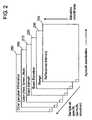
- 3D data sets collected by a 3D rangefindermay be presented as a visual display to a user in several different ways.
- the visualization techniquesfall broadly into two classes, 3D displayed images and 2D displayed images.
- a 3D displayed image formatis one in which the user may select a particular 3D viewpoint and then view the 3D range data as geometric figures in perspective projection or in orthogonal projection or via some other projection within a 2D computer image.
- Techniques for creating 3D displayed imagesare well known from computer graphics textbooks such as “Computer Graphics: Principles and Practice in C” by James D. Foley, Andries van Dam, Steven K. Feiner, and John F. Hughes (Addison Wesley 1995).
- Well-known formats for a 3D displayed imagemay have the 3D range data samples represented as 3D points (also known as a point cloud) in which the same color is assigned to all points, in which false color is assigned to each point based on its range, in which color is assigned to each point based on its reflectance intensity (strength of the signal returned from a surface to the 3D rangefinder), or in which points are colored via any other scheme.
- 3D range data pointsmay be linked together into a 3D mesh using well known computer graphics techniques, such that neighboring points are connected via lines within the display. The lines of the mesh may be colored using any of the techniques discussed above using well-known computer graphics techniques.
- the 3D range data pointsmay be linked together into a surface using well known computer graphics techniques.
- the surfacemay have range values interpolated between actual data points using linear, quadratic, cubic, or any well-known surface interpolation technique.
- the color of the surface at each displayed pixelmay be determined in any of a number of well-known ways, including computing simulated lighting effects based on the orientation of the interpolated surface, interpolating reflectance intensity values measured at each data point, mapping a 2D image or any other function to the 3D surface using well-known texture-mapping techniques, combinations thereof, or any using other well-known techniques for surface rendering.
- a 2D displayed imageis one in which the 3D range data set is inherently represented as a 2D image.
- There are several well-known techniques for creating 2D displayed imagessince the data from a typical 3D rangefinder is obtained by scanning in two dimensions, typically azimuth and elevation.
- the resulting datacan naturally be represented as a 2D image in spherical projection, where the azimuth angle of a 3D sample is represented as the horizontal or X axis and the elevation angle is represented as vertical or Y axis on the display, and each pixel represents one or more 3D data points depending on the scale chosen.
- the 2D displayed imageneed not be represented in spherical projection, but in any other well-known projection of a 3D data set to a 2D display.
- each pixelmay have a multiplicity of associated values stored with it, including precise azimuth angle value 210 , precise elevation angle value 220 , range value 230 , reflectance value 240 , color 250 (RGB), and any other useful values 260 .
- a useful valuemight be some other attribute associated with the pixel.
- the color of each pixel within the 2D displayed imagemay be determined in any of a number of well-known formats.
- a Range Imagehas a false color assigned to each pixel based on its range.
- a Reflectance Imagehas a color assigned to each pixel based on the intensity of the reflected laser beam.
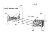
- a Registered Color Imagehas a color assigned to each pixel based on the color obtained from a color sensor such as a 2D digital camera such that the range data and color data are aligned as shown in FIG. 3 .
- a Registered Color Imagemay typically be created by the steps of capturing a 3D range data set with a 3D rangefinder and displaying it as a Reflectance Image 310 , capturing a 2D image using a calibrated digital color camera and displaying it as a 2D color image 320 , identifying corresponding features between the two 2D images such as 311 and 321 , 312 and 322 , 313 and 323 , and 314 and 324 , using the locations of the corresponding features to compute the pose (location and orientation) of the 2D digital color camera, using the camera pose information to compute the optical path from the camera into the 3D data set, and applying the color from each pixel of the 2D color image to corresponding points of the 3D data set displayed as a 2D image.
- Range Imageexamples of a Range Image, a Reflectance Image, and a Registered Color Image may be found in an article by Lars Nyland, Anselmo Lastra, David K. McAllister, Voicuffy, and Chris McCue, titled “Capturing, Processing and Rendering Real-World Scenes”, Videometrics and Optical Methods for 3D Shape Measurement, Electronic Imaging 2001, Photonics West, SPIE Vol. 4309 Jan. 22, 2001.
- the ability to create and display a Range Image, a Reflectance Image, and a Registered Color Imagehas been available in the DsControl, DsColor, and other software provided to DeltaSphere 3000 customers beginning some time ago.
- the geometric correspondence between the distinct 3D range data setscan be determined.
- a point in one 3D frame of referencecan be transformed into the coordinates of a second frame of reference using a 3D rigid transformation comprising three rotation angles plus a 3D translation.
- the critical component of registrationis the 3D transformation defining how to convert the 3D data points in one scan or 3D range data set into the 3D coordinate space of another 3D range data set. Also it may be desired to convert the 3D data points in one scan or 3D range data set into a separate common 3D coordinate space.
- both sets of 3D datamay be easily combined into a single coordinate space and display and measurement using both data sets is facilitated.
- 3D range data setsmay then be added serially in like fashion, all to a common frame of reference.
- the geometric correspondence between two or more 3D range data setsmay be established.
- Thisis also known as registering two or more 3D range data sets.
- 3D data setsmight be acquired from the left front, left side, left rear, right rear, right side, and right front viewpoints and then all of these 3D data sets would be registered in order to create a single complete 3D model of the vehicle.
- Several existing software packagesprovide this capability—for example the PolyWorks software package from Innovmetric, such as described on the internet at URL http://www.innovmetric.com/ includes a software tool called ImAlign.
- the useris allowed to specify multiple pairs of corresponding points from two 3D range data sets and to either use those correspondences directly or as a starting point for an algorithm that refines the geometric correspondence such as that disclosed in P. J. Besl and N. D. McKay, “A Method for Registration of 3-D Shapes”, IEEE Transactions on Pattern Analysis and Machine Intelligence, Vol. 14 (1992), No. 2, 239-256.
- Well-known mathematical techniquesallow the calculation of the necessary scan-to-scan 3D transformation from multiple pairs of points. By simple linear algebra, three corresponding pairs of points are the minimum necessary to solve for the desired transformation matrix.
- well known methodsallow the transformation matrix to be solved by finding three corresponding planes. Additional references on registration techniques may be found in Fausto Bernardini and Holly Rushmeier, “The 3D Model Acquisition Pipeline” Volume 21 (2002), number 2 pp. 149-172 COMPUTER GRAPHICS forum.
- multiple 3D data setsare then merged together into one new 3D data file using the 3D transformation obtained from the registration process, and the results displayed as a 3D point display.
- the usermay then typically select points of interest within the combined 3D data set and make measurements, such as distance from one point to another, or perpendicular distance from one surface to another, or area of a surface, or volume bounded by a set of surfaces.
- the merger of multiple 3D data sets into a single 3D display with many thousands or millions of data pointsmay create a very complicated and often confusing display to a user. This may make it difficult for a user to identify and specify the correct features of interest for measurement. It would be advantageous to have additional methods for making and displaying measurements in ways that a user might find more natural or easier to understand. As such, user productivity would be increased, and new applications for 3D rangefinder technology could be enabled.
- the present invention and its various embodimentsseek to address at least some of the above needs and problems while attempting to deliver one or more of the above advantages. Further, the present invention provides a number of embodiments that seek to allow a user to more effectively make and display measurements based upon at least two 3D range data sets. As such, the user can more productively interact with 3D range data sets to allow applications to be better served.
- the present inventionprovides methods, computer program products, and apparatuses for making and displaying measurements based upon at least two 3D range data sets in various embodiments.
- the present inventionprovides a method for making measurements between two 3D range data sets obtained using a 3D rangefinder device.
- the methodcomprises the steps of providing a first 3D range data set and providing a second 3D range data set.
- a 3D transformation between the first 3D range data set and the second 3D range data setsis computed.
- the first 3D range data setis represented as a first displayed image. At least a first feature is identified within the first displayed image, while at least a second feature is identified within the second displayed image.
- the methodincludes the step of computing a measurement based on at least the first feature and the second feature utilizing the 3D transformation between the first 3D range set and the second 3D range data set. Thereafter, the computed measurement may be displayed within at least one of the first displayed image and the second displayed image.
- a second embodiment of the inventionprovides a computer program product stored in computer readable media for execution in at least one processor.
- the computer program productmay be used for making measurements between two 3D range data sets obtained using a 3D rangefinder device.
- a number of software modulescomprise this embodiment.
- a first software module for providing a first 3D range data set and a second software module for providing a second 3D range data setare both included.
- the embodimentprovides a third software module for computing a 3D transformation between the first 3D range data set and the second 3D range data sets.
- Fourth and fifth software modulesare included to represent the first 3D range data set as a first displayed image and to represent the second 3D range data set as a second displayed image respectively.
- a sixth software module for identifying at least a first feature within the first displayed imageis provided.
- the embodimentincludes a seventh software module for identifying at least a second feature within the second displayed image.
- the embodimentprovides an eighth software module for computing a measurement based on at least the first feature and the second feature utilizing the 3D transformation between the first 3D range set and the second 3D range data set.
- a ninth software module for displaying the computed measurement within at least one of the first displayed image and the second displayed imageis provided. Yet other embodiments related to the preceding computer program product embodiment are also provided.
- a third embodiment of the present inventioncomprises an apparatus for making measurements between two 3D range data sets obtained using a 3D rangefinder device.
- the apparatusincludes at least one computer processor therein, and a computer program product executing within the at least one computer processor.
- a first software moduleis included for providing a first 3D range data set and a second software module for providing a second 3D range data set.
- the embodimentprovides a third software module for computing a 3D transformation between the first 3D range data set and the second 3D range data sets.
- Fourth and fifth software modulesare included to represent the first 3D range data set as a first displayed image and to represent the second 3D range data set as a second displayed image respectively.
- a sixth software module for identifying at least a first feature within the first displayed imageis provided.
- the embodimentincludes a seventh software module for identifying at least a second feature within the second displayed image.
- the embodimentfurther provides an eighth software module for computing a measurement based on at least the first feature and the second feature utilizing the 3D transformation between the first 3D range set and the second 3D range data set.
- a ninth software module for displaying the computed measurement within at least one of the first displayed image and the second displayed imageis included. Further embodiments related to the apparatus embodiment are provided by the present invention.
- FIG. 1is a diagram illustrating a conventional 3D scanning laser range finder.
- FIG. 2is a diagram illustrating multiple example values that could be associated with a pixel within a 2D image representing a 3D range data set.
- FIG. 3is a diagram illustrating corresponding range and color information for a registered color image representing a 3D range data set.
- FIG. 4is a diagram illustrating one example of the acquisition of a 3D range data set.
- FIG. 5is a diagram illustrating an example display of multiple images representing two 3D range data sets, according to some embodiments of the present invention.
- FIG. 6is a diagram illustrating a registered color image from one 3-D data set and a reflectance image from another 3-D data set, according to some embodiments of the present invention.
- FIG. 7is a diagram illustrating a registered color image from one 3-D data set and a reflectance image from another 3-D data set showing a measurement between two points within a single 3d data set and image thereof, according to some embodiments of the present invention.
- FIG. 8is a diagram illustrating a registered color image from one 3-D data set and a reflectance image from another 3-D data set showing measurement between two points in two different 3-D data sets and images thereof, according to some embodiments of the present invention.
- FIG. 9is a diagram illustrating a registered color image from one 3-D data set and a reflectance image from another 3-D data set showing measurement between two points in two different 3-D data sets and images thereof, according to some embodiments of the present invention.
- FIG. 10is a diagram illustrating a registered color image from one 3-D data set and a reflectance image from another 3-D data set showing measurement between two points in two different 3-D data sets and images thereof, according to some embodiments of the present invention.
- FIG. 11is a diagram illustrating a registered color image from one 3-D data set and a reflectance image from another 3-D data set showing measurement between two points in two different 3-D data sets and images thereof, according to some embodiments of the present invention.
- the present inventionprovides a method for making measurements between two 3D range data sets obtained using a 3D rangefinder device.
- the methodcomprises the steps of providing a first 3D range data set and providing a second 3D range data set.
- a 3D transformation between the first 3D range data set and the second 3D range data setsis computed.
- the first 3D range data setis represented as a first displayed image. At least a first feature is identified within the first displayed image, while at least a second feature is identified within the second displayed image.
- the methodincludes the step of computing a measurement based on at least the first feature and the second feature utilizing the 3D transformation between the first 3D range set and the second 3D range data set. Thereafter, the computed measurement may be displayed within at least one of the first displayed image and the second displayed image.
- the computed measurementsmay be displayed in the first displayed image only, in the second displayed image only, or in both the first displayed image and the second displayed image in combination.
- displaying the computed measurementmay represent a number of displays.
- the computed measurementmay be displayed as a measurement point display, a plurality of measurement points displayed, a measurement line display, a plurality of measurement lines displayed, a measurement surface displayed, a plurality of measurement surfaces displayed, or the like.
- the computer displaymay be a value displayed, a plurality of values displayed, a measurement volume displayed, a plurality of measurement volumes displayed, a measurement feature displayed, and a plurality of measurement features displayed.
- the computed measurementmay also be represented as combinations of the preceding displays.
- Some embodimentsfurther include at least a third display. In these cases, the computed measurement may be displayed in at least the third displayed image, displayed in the first displayed image, displayed in the second displayed image, and displayed in some combination of the preceding displayed images.
- the second 3D range data setmay be obtained in many ways.
- a second 3D range data setcan be obtained by the same 3D rangefinder device as the first 3D range data set but obtained from a different 3D location than the first 3D range data set.
- the second 3D range data setmay be obtained by the same 3D rangefinder device as the first 3D range data set from the same 3D location but obtained at a different resolution than the first 3D range data set.
- the second 3D range data setcan be obtained by the same 3D rangefinder device as the first 3D range data set from the same 3D location but obtained at a different time than the first 3D range data set.
- the second 3D range data setcan be being obtained by using a different 3D rangefinder device than was used for the first 3D range data set and obtained at the same 3D location as the first 3D range data set. Further, the second 3D range data set may be obtained by using a different 3D rangefinder device than was used for the first 3D range data set and obtained from a different 3D location. In addition, a second 3D range data set could be obtained by a different 3D rangefinder device than was used for the first 3D range data set and obtained at a different time. Range data sets, such as the first 3D range data set, second 3D range data set, or the like, can be provided from various sources.
- a scanning laser rangefinder using time of flight range measurement principles, a scanning laser rangefinder using phase comparison range measurement principles, or a scanning laser rangefinder using any other range measurement principlescould be used to provide 3D range data sets.
- An imaging laser rangefinder range camera using time of flight range measurement principles, an imaging laser rangefinder range camera using phase comparison range measurement principles, or an imaging laser rangefinder range camera using any other range measurement principlesmight provide 3D range data sets.
- a triangulation rangefinder, a stereo image rangefinder, a multiple image rangefinder, any other device that acquires a multiplicity of range data points simultaneouslymay be used.
- any other device that acquires a multiplicity of range data points over a period of time, or combinations of the abovecould be used to provide 3D range data sets.
- the first displayed image, the second displayed image, or both,could comprise a 2D image.
- a 2D imagemight comprise range values from the 3D rangefinder device converted to monochrome, or a 2D range image comprising range values from the 3D rangefinder device converted to false color.
- a 2D imagecould be a 2D reflectance image comprising intensity values of the rangefinding signal reflected from a physical surface and thereafter received by the 3D rangefinder device converted to monochrome, or a 2D reflectance image comprising intensity values of the rangefinding signal reflected from a physical surface and thereafter received by the 3D rangefinder device converted to false color.
- a 2D imagemay be registered.
- itmay be a 2D registered color image comprising a color camera image previously registered with 3D range data, a 2D registered color image wherein the image is acquired from the same perspective as the 3D range data set, a 2D registered color image wherein the image is acquired from a different perspective than the 3D range data set, a 2D registered color image wherein the image is acquired with the same resolution as the 3D range data set, or a 2D registered color image wherein the image is acquired with different resolution from the 3D range data set.
- a 2D imagecan be a 2D image displayed in spherical projection format, a 2D image displayed in any other 3D-to-2D projection format, a 2D registered monochrome image comprising a monochrome camera image previously registered with 3D range data, or the like. Combinations of the above are also possible.
- the first displayed image, the second displayed image, or bothcould comprise a 3D image.
- a 3D imagemight comprise a 3D point display, a 3D point display in orthogonal projection, or a 3D point display in perspective projection.
- a 3D polygonal mesh display, a 3D polygonal mesh in orthogonal projection display, or a 3D polygonal mesh in perspective projection displaymay comprise the 3D image.
- the 3D imagecould be a 3D surface geometry display, a 3D surface geometry display in orthogonal projection, or a 3D surface geometry display in perspective projection.
- one or more 3D range data setscould each be represented by at least two images.
- at least three range data setsare provided, such that the respective features can be identified within the respective displayed images.
- the measurementcan be computed by computing the measurement between at least two 3D range data sets in parallel.
- the measurementcould be computed by computing the measurement between at least two 3D range data sets simultaneously.
- a measurementmight be computed by computing the measurement between at least two 3D range data sets serially.
- combinations of the precedingcould be used to compute a measurement in embodiments.
- the method embodimentscan be implemented in any number of ways.
- the methodcould be implemented in a computer processor executing a suitable computer software program product therein.
- the methodmay be implemented in a suitable computer software program product embodied on computer readable tangible media.
- identifying the first feature, the second feature, or bothcould use various facilities.
- a featurecould be identified by using a computer cursor controlled by a mouse to identify, by using a computer cursor controlled by a pointing stick to identify, or by using a computer cursor controlled by a joystick to identify.
- a featurecould be identified by using a computer cursor controlled by a touch pad to identify, using software to identify, or combinations of the facilities above allowing a user to identify features. For embodiments, at least part of identifying features could be done automatically.
- orienting a measurement perpendicularly from a specified surface, placing a feature restricted to a specified surface, or placing a feature in the center of a circular featurecould be done automatically, at least in part.
- combinations of the abovecould be used.
- Sub-pixel interpolationcan be used in any displayed image wherein a software tool may allow the user to estimate and specify the location of a feature anywhere within a pixel and not just at its origin. Interpolation may be used between measured 3D range data points on surfaces in any 3D displayed image, wherein a software tool may allow the user to estimate and specify the location of a feature anywhere upon a surface even if that particular location is not directly associated with a measured 3D range data point. Estimates of the centers of features can be used such that user may estimate and specify the location of the center of a feature even if the particular pixel at that chosen center appears no different from adjacent pixels.
- holes and data interpolated across holescan be used, wherein the range finder device did not acquire a range measurement and wherein a software tool may allow the user to estimate and specify the location of a feature anywhere within a hole even though that particular location is not directly associated with a measured 3D range data point.
- a software toolmay allow the user to estimate and specify the location of a feature anywhere within a hole even though that particular location is not directly associated with a measured 3D range data point.
- one embodiment of the inventionprovides a computer program product stored in computer readable media for execution in at least one processor for making measurements between two 3D range data sets obtained using a 3D range finder device.
- a number of software modulescomprise this embodiment.
- a first software module for providing a first 3D range data set and a second software module for providing a second 3D range data setare both included.
- the embodimentprovides a third software module for computing a 3D transformation between the first 3D range data set and the second 3D range data sets.
- Fourth and fifth software modulesare included to represent the first 3D range data set as a first displayed image and to represent the second 3D range data set as a second displayed image respectively.
- a sixth software module for identifying at least a first feature within the first displayed imageis provided.
- the embodimentincludes a seventh software module for identifying at least a second feature within the second displayed image.
- the embodimentprovides an eighth software module for computing a measurement based on at least the first feature and the second feature utilizing the 3D transformation between the first 3D range set and the second 3D range data set.
- a ninth software module for displaying the computed measurement within at least one of the first displayed image and the second displayed imageis provided.
- the present inventionprovides an apparatus in yet another embodiment.
- the apparatusmay be used for making measurements between two 3D range data sets obtained using a 3D rangefinder device.
- the apparatusincludes at least one computer processor therein, and a computer program product executing within the at least one computer processor.
- a first software moduleis included for providing a first 3D range data set and a second software module for providing a second 3D range data set.
- the embodimentprovides a third software module for computing a 3D transformation between the first 3D range data set and the second 3D range data sets.
- Fourth and fifth software modulesare included to represent the first 3D range data set as a first displayed image and to represent the second 3D range data set as a second displayed image respectively.
- a sixth software module for identifying at least a first feature within the first displayed imageis provided.
- the embodimentincludes a seventh software module for identifying at least a second feature within the second displayed image.
- the embodimentfurther provides an eighth software module for computing a measurement based on at least the first feature and the second feature utilizing the 3D transformation between the first 3D range set and the second 3D range data set.
- a ninth software module for displaying the computed measurement within at least one of the first displayed image and the second displayed imageis included.
- the present inventionalso provides other embodiments related to the preceding. Further, the prior discussion related to the method embodiments applies also to the apparatus embodiments. Next we discuss more details regarding various embodiments of the present invention.
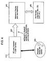
- a 3D rangefinder 410is used to acquire a 3D range data set 420 from a physical object or scene 430 .
- One 3D rangefinder 410 embodiment shown in FIG. 1is a laser scanning 3D rangefinder 100 comprising a time-of-flight laser rangefinder 140 , elevation scanning mirror 120 which is rotated by elevation motor 145 , and azimuth rotating motor assembly 130 .
- the 3D rangefinder such as shown in FIG. 1also includes an embedded computer 150 for interfacing to and controlling the rangefinder 140 , elevation motor 145 , and azimuth motor 130 .
- the embedded computer 150communicates with any external computer via Ethernet 160 and also transfers data samples from the rangefinder, performs necessary data processing such as applying calibration tables, and passes data samples to the external computer for visualization, storage, and subsequent processing.
- the 3D range data set 420 for each data samplecomprising intensity, range, azimuth, and elevation values is transferred to an external computer and presented in a computer display 440 for evaluation and control of laser scanning parameters such as resolution and speed.
- the datais simultaneously stored in a computer file 450 for later processing and display.
- Two or more 3D range data sets such as 450are typically acquired using the laser scanning 3D rangefinder 410 located at different locations around the scene. Other techniques for acquiring multiple 3D data sets 450 may be used including using the same rangefinder 410 at different times or at different resolutions and using two or more different 3D rangefinders 410 . The operator or user must take care that there is some area of the scene that is overlapped by two or more acquisition scans so that a subsequent registration step may be readily performed.
- each data set to be registeredis presented to a user via a computer display as a 3D set of points and the user then performs the step of identifying corresponding features within the 3D images representing the multiple data sets.
- the usermight use a mouse or other control device to position a cursor such as a crosshairs over a desired pixel within a 3D displayed image.
- a cursorsuch as a crosshairs
- the corresponding X, Y, and Z values for that pixelare known, having been used to create the displayed pixel using well-known 3D computer graphics techniques.
- the usernext proceeds to select as many pairs of features as desired as input to the next step of calculating the 3D transformation between two range data sets.
- a minimum of three non-collinear pairs of corresponding 3D (X, Y, Z) pointsis needed to calculate the desired 3D rigid transformation using well-known techniques to solve for 3 rotation angles plus 3 translations, including those disclosed for example in O. D. Faugeras and M. Hebert “The representation, recognition, and locating of 3-d objects”, International Journal of Robotic Research, 5(3):27-52, Fall 1986. More points may be used along with well-known least-squares minimization techniques to obtain a better fit, as disclosed for example in K. Arun, T. Huang, and S. Blostein, “Least-Squares Fitting of Two 3D Point Sets”, in IEEE Transactions on Pattern Analysis and Machine Intelligence, vol. 9 (1987), 698-700.
- the initial sets of corresponding featuresmay be used as the starting points for algorithms such as the iterated closest point technique disclosed in P. J. Besl and N. D. McKay, “A Method for Registration of 3-D Shapes”, IEEE Transactions on Pattern Analysis and Machine Intelligence, Vol. 14 (1992), No. 2, 239-256. Additional references to registration techniques which might be used are given in Fausto Bernardini and Holly Rushmeier, “The 3D Model Acquisition Pipeline” Volume 21 (2002), number 2 pp. 149-172 COMPUTER GRAPHICS forum.
- the new inventionenables the user to work with more natural and easy-to-understand display formats for specification and display of measurements.
- each data set to be used for measurementis presented to a user via a computer display.
- the usermay select from multiple formats which may be used for displaying this data as shown in FIG. 5 .
- data from the first 3D data setis represented in window 510 , representing a 2D Reflectance Image for example
- window 520representing a 3D geometric image on the display screen
- data from the second 3D data setis represented in windows 530 and 540 on the display screen.
- Window 540may represent 2D Reflectance Image #2
- window 530can represent a 2D Registered Color Image, for example.
- a 3D displayed image format such as 520is one in which the user may select a particular 3D viewpoint and then view the 3D range data as geometric figures in perspective projection or in orthogonal projection or via some other projection.
- Techniques for displaying collections of 3D dataare well known from computer graphics textbooks such as “Computer Graphics: Principles and Practice in C” by James D. Foley, Andries van Dam, Steven K. Feiner, and John F. Hughes (Addison Wesley 1995).
- the displaymay represent range data samples as 3D points (also known as a point cloud) which may all be colored a single color, which may have false color assigned to each point based on its range, which may have color assigned to each point based on the intensity of the reflected laser beam, or colored via any other scheme.
- the 3D range data pointsmay be linked together into a displayed mesh using well known computer graphics techniques, such that neighboring points are connected via lines within the display.
- the lines of the meshmay be colored using any of the techniques discussed above using well-known computer graphics techniques.
- the 3D range data pointsmay be linked together into a surface using well known computer graphics techniques.
- the surfacemay have range values interpolated between actual data points using linear, quadratic, cubic, or any well-known surface interpolation technique.
- the color of the surface at each displayed pixelmay be determined in any of a number of well-known ways, including computing simulated lighting effects based on the orientation of the interpolated surface, interpolating reflectance intensity values measured at each data point, mapping a 2D image or any other function to the 3D surface using well-known texture-mapping techniques, combinations thereof, or any using other well-known techniques for surface rendering.
- a 2D displayed image format such as 510 , 530 , or 540is one in which the 3D data set is represented as a 2D image.
- the data from a typical 3D range finderis obtained by scanning in two dimensions, typically azimuth and elevation.
- the resulting datacan naturally be represented as a 2D image in spherical projection, where the azimuth angle of a 3D sample is represented as the horizontal or X axis and the elevation angle is represented as vertical or Y axis on the display, and each pixel represents one or more 3D data points depending on the scale chosen.
- the 2D displayed imageneed not be represented in spherical projection, but in any other well-known projection of a 3D data set to a 2D display.
- each pixelmay have a multiplicity of associated values stored with it, including precise azimuth angle value 210 , precise elevation angle value 220 , range value 230 , reflectance value 240 , color 250 (RGB), and any other useful values 260 .
- the color of each pixel with in the 2D displayed imagemay be determined in any of a number of well-known formats.
- a Range Imagehas a false color assigned to each pixel based on its range.
- a Reflectance Imagesuch as 510 or 540 has a color assigned to each pixel based on the intensity of the reflected laser beam.
- a Registered Color Imagesuch as 530 has a color assigned to each pixel based on the color obtained from a color sensor such as a 2D digital camera such that the range data and color data are aligned as shown in FIG. 3 .
- the userspecifies measurement features in images by identifying a particular pixel within a 2D or 3D displayed image which will allow the calculation of the X, Y, and Z coordinates of the data represented by that pixel.
- the usermight use a mouse or other control device to position a cursor such as a crosshairs over a desired pixel within a 2D reflectance image. Since the azimuth 210 , elevation 220 , and range 230 values for a 3D range sample are associated with the pixel, simple trigonometry can be used to convert from spherical to Cartesian coordinates and obtain the corresponding X, Y, and Z values.
- the imagemight be zoomed in so that an image data pixel covers a 10 ⁇ 10 array of pixels on the screen.
- the cursorcould be used to indicate a sub-pixel location to within 0.1 pixel and more accurate X, Y, and Z values can be readily interpolated based on the sub-pixel location and azimuth, elevation, and range values associated with neighboring pixels.
- a point on a 3D surfacemight be selected with a cursor and then the X, Y, and Z values may be calculated by interpolating between the actual 3D range data points that define the surface.
- the methodcan be extended to cover holes and data interpolated across holes.
- holesare places where the 3D rangefinder did not acquire a range measurement because of insufficient returned laser energy or other reasons.
- An interactive or automated software toolmay allow the user to estimate and specify the location of a feature point anywhere within a hole even though that particular location is not directly associated with a measured 3D range data point. For example the user may interactively or automatically estimate and specify the location of the center of a circular hole in a 2D or 3D displayed image. Calculation of the bi-linear, bi-cubic, or other interpolation of surrounding measured range data points can then yield the estimated feature point location.
- FIG. 6The process of displaying images representing multiple data sets is illustrated in FIG. 6 .
- the upper window 610is a 2D Registered Color Image representing one 3D data set acquired with a 3D rangefinder located near the head of a simulated murder victim, for example.
- the lower window 620is a 2D Reflectance Image representing a different 3D data set acquired with the 3D rangefinder located near the foot of the victim.
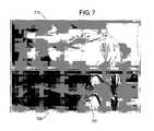
- FIG. 7contains the same two 3D data sets as FIG. 6 , represented by a 2D Registered Color Image 710 and a 2D Reflectance Image 720 .
- FIG. 7illustrates using conventional techniques for making and displaying measurements within a single 3D data set. These techniques have been available in DeltaSphere software since some time ago, for example. Two points have been selected in the Reflectance Image 720 and their respective X, Y, and Z coordinates have been determined from the underlying 3D data set as discussed previously. Using conventional techniques the distance between them has been calculated and a measurement line and measurement figures 721 are displayed within the Reflectance Image 720 .
- FIG. 8contains the same two 3D data sets as FIG. 6 , represented by a 2D Registered Color Image 810 and a 2D Reflectance Image 820 .
- FIG. 8illustrates one aspect of the present invention, wherein one endpoint 821 of a measurement has been selected on the victim's foot in the Reflectance Image 820 and another endpoint 811 has been selected on the bed within the Registered Color Image 810 . Even though endpoint 821 is visible in both images 810 and 820 , it has been specified within the image where it is most apparent and easy to select, enhancing ease-of-use and accuracy.
- the measurement line and measurement figuresare represented in both 2D images as 812 and 822 , respectively.
- the inventionallows the user to easily select measurement features within each 3D data set using display formats where the feature is most readily perceived, and furthermore provides the resulting measurement information to the user within the proper context to aid in understanding.
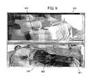
- FIG. 9contains the same two 3D data sets as FIG. 6 , represented by a 2D Registered Color Image 910 and a 2D Reflectance Image 920 .
- FIG. 9illustrates another aspect of the present invention, wherein one endpoint 921 of a measurement has been selected between the victim's feet in the Reflectance Image 920 and another endpoint 911 has been selected on the bed within the Registered Color Image 910 . Note that while the endpoint 911 is visible in both images 910 and 920 , in this case the endpoint 921 is only visible within the Reflectance Image 920 , illustrating another advantage of the present invention.
- the measurement line and figures 922are shown in 2D Reflectance Image 920 .
- FIG. 10contains the same two 3D data sets as FIG. 6 , represented by a 2D Registered Color Image 1010 and a 2D Reflectance Image 1020 .
- FIG. 10illustrates another aspect of the present invention, wherein one endpoint 1021 of a measurement has been selected between the victim's feet in the Reflectance Image 1020 and another endpoint 1011 has been selected on the victim's chin within the Registered Color Image 1010 .
- endpoint 1011is visible only in image 1010
- the endpoint 1021is visible only within image 1020 , illustrating another advantage of the present invention.
- FIG. 11contains the same two 3D data sets as FIG. 6 , represented by a 2D Registered Color Image 1110 and a 2D Reflectance Image 1120 .
- FIG. 11illustrates another aspect of the present invention, wherein one endpoint 1121 of a measurement has been selected on the victim's foot in the Reflectance Image 1120 and another endpoint 1111 has been selected on the victim's forehead within the Registered Color Image 1110 .
- the measurement line and figures 1112 and 1122are shown in images 1110 and 1120 respectively, providing additional context and clarity to the user.
- embodiments of the present inventioncan address problems noted above.
- embodimentsprovide an improvement upon existing methods which rely on specifying measurement features within confusing and often-ambiguous 3D point displays of multiple 3D data sets which have first been combined into a single 3D data set.
- the embodimentsprovide a natural, easy-to-use method of specifying and displaying measurements between multiple 3D range data sets that allow one to obtain a more complete and readily understood measurement of a scene or object.
Landscapes
- Physics & Mathematics (AREA)
- Engineering & Computer Science (AREA)
- Electromagnetism (AREA)
- Computer Networks & Wireless Communication (AREA)
- General Physics & Mathematics (AREA)
- Radar, Positioning & Navigation (AREA)
- Remote Sensing (AREA)
- Length Measuring Devices By Optical Means (AREA)
Abstract
Description
Claims (24)
Priority Applications (1)
| Application Number | Priority Date | Filing Date | Title |
|---|---|---|---|
| US11/351,246US7477359B2 (en) | 2005-02-11 | 2006-02-09 | Method and apparatus for making and displaying measurements based upon multiple 3D rangefinder data sets |
Applications Claiming Priority (2)
| Application Number | Priority Date | Filing Date | Title |
|---|---|---|---|
| US65220805P | 2005-02-11 | 2005-02-11 | |
| US11/351,246US7477359B2 (en) | 2005-02-11 | 2006-02-09 | Method and apparatus for making and displaying measurements based upon multiple 3D rangefinder data sets |
Publications (2)
| Publication Number | Publication Date |
|---|---|
| US20060193521A1 US20060193521A1 (en) | 2006-08-31 |
| US7477359B2true US7477359B2 (en) | 2009-01-13 |
Family
ID=36931978
Family Applications (1)
| Application Number | Title | Priority Date | Filing Date |
|---|---|---|---|
| US11/351,246Expired - Fee RelatedUS7477359B2 (en) | 2005-02-11 | 2006-02-09 | Method and apparatus for making and displaying measurements based upon multiple 3D rangefinder data sets |
Country Status (1)
| Country | Link |
|---|---|
| US (1) | US7477359B2 (en) |
Cited By (27)
| Publication number | Priority date | Publication date | Assignee | Title |
|---|---|---|---|---|
| US20060181527A1 (en)* | 2005-02-11 | 2006-08-17 | England James N | Method and apparatus for specifying and displaying measurements within a 3D rangefinder data set |
| US20060182314A1 (en)* | 2005-02-11 | 2006-08-17 | England James N | Method and apparatus for displaying a calculated geometric entity within one or more 3D rangefinder data sets |
| US20080046221A1 (en)* | 2006-06-28 | 2008-02-21 | Sam Stathis | Method and system for automatically performing a study of a multidimensional space |
| US20080310757A1 (en)* | 2007-06-15 | 2008-12-18 | George Wolberg | System and related methods for automatically aligning 2D images of a scene to a 3D model of the scene |
| US20140022555A1 (en)* | 2010-05-10 | 2014-01-23 | Faro Technologies, Inc. | Method for optically scanning and measuring an environment |
| US20150029516A1 (en)* | 2012-01-25 | 2015-01-29 | Faro Technologies, Inc. | Device for optically scanning and measuring an environment |
| US8997362B2 (en) | 2012-07-17 | 2015-04-07 | Faro Technologies, Inc. | Portable articulated arm coordinate measuring machine with optical communications bus |
| US9009000B2 (en) | 2010-01-20 | 2015-04-14 | Faro Technologies, Inc. | Method for evaluating mounting stability of articulated arm coordinate measurement machine using inclinometers |
| US9113023B2 (en) | 2009-11-20 | 2015-08-18 | Faro Technologies, Inc. | Three-dimensional scanner with spectroscopic energy detector |
| US9134339B2 (en) | 2013-09-24 | 2015-09-15 | Faro Technologies, Inc. | Directed registration of three-dimensional scan measurements using a sensor unit |
| US9163922B2 (en) | 2010-01-20 | 2015-10-20 | Faro Technologies, Inc. | Coordinate measurement machine with distance meter and camera to determine dimensions within camera images |
| US9168654B2 (en) | 2010-11-16 | 2015-10-27 | Faro Technologies, Inc. | Coordinate measuring machines with dual layer arm |
| US9210288B2 (en) | 2009-11-20 | 2015-12-08 | Faro Technologies, Inc. | Three-dimensional scanner with dichroic beam splitters to capture a variety of signals |
| US9229106B2 (en) | 2010-08-13 | 2016-01-05 | Ryan Dotson | Enhancement of range measurement resolution using imagery |
| USRE45854E1 (en) | 2006-07-03 | 2016-01-19 | Faro Technologies, Inc. | Method and an apparatus for capturing three-dimensional data of an area of space |
| US9372265B2 (en) | 2012-10-05 | 2016-06-21 | Faro Technologies, Inc. | Intermediate two-dimensional scanning with a three-dimensional scanner to speed registration |
| US9513107B2 (en) | 2012-10-05 | 2016-12-06 | Faro Technologies, Inc. | Registration calculation between three-dimensional (3D) scans based on two-dimensional (2D) scan data from a 3D scanner |
| US9529083B2 (en) | 2009-11-20 | 2016-12-27 | Faro Technologies, Inc. | Three-dimensional scanner with enhanced spectroscopic energy detector |
| US9551575B2 (en) | 2009-03-25 | 2017-01-24 | Faro Technologies, Inc. | Laser scanner having a multi-color light source and real-time color receiver |
| US9607239B2 (en) | 2010-01-20 | 2017-03-28 | Faro Technologies, Inc. | Articulated arm coordinate measurement machine having a 2D camera and method of obtaining 3D representations |
| US9628775B2 (en) | 2010-01-20 | 2017-04-18 | Faro Technologies, Inc. | Articulated arm coordinate measurement machine having a 2D camera and method of obtaining 3D representations |
| US9645240B1 (en)* | 2010-05-10 | 2017-05-09 | Faro Technologies, Inc. | Method for optically scanning and measuring an environment |
| US10067231B2 (en) | 2012-10-05 | 2018-09-04 | Faro Technologies, Inc. | Registration calculation of three-dimensional scanner data performed between scans based on measurements by two-dimensional scanner |
| US10175037B2 (en) | 2015-12-27 | 2019-01-08 | Faro Technologies, Inc. | 3-D measuring device with battery pack |
| US10281259B2 (en) | 2010-01-20 | 2019-05-07 | Faro Technologies, Inc. | Articulated arm coordinate measurement machine that uses a 2D camera to determine 3D coordinates of smoothly continuous edge features |
| US10724853B2 (en) | 2017-10-06 | 2020-07-28 | Advanced Scanners, Inc. | Generation of one or more edges of luminosity to form three-dimensional models of objects |
| US11315282B2 (en) | 2019-08-23 | 2022-04-26 | Faro Technologies, Inc. | System and method of imaging evidence at a scene |
Families Citing this family (30)
| Publication number | Priority date | Publication date | Assignee | Title |
|---|---|---|---|---|
| US7477360B2 (en)* | 2005-02-11 | 2009-01-13 | Deltasphere, Inc. | Method and apparatus for displaying a 2D image data set combined with a 3D rangefinder data set |
| US7403268B2 (en)* | 2005-02-11 | 2008-07-22 | Deltasphere, Inc. | Method and apparatus for determining the geometric correspondence between multiple 3D rangefinder data sets |
| US7477359B2 (en) | 2005-02-11 | 2009-01-13 | Deltasphere, Inc. | Method and apparatus for making and displaying measurements based upon multiple 3D rangefinder data sets |
| US7551771B2 (en)* | 2005-09-20 | 2009-06-23 | Deltasphere, Inc. | Methods, systems, and computer program products for acquiring three-dimensional range information |
| DE202006005643U1 (en)* | 2006-03-31 | 2006-07-06 | Faro Technologies Inc., Lake Mary | Device for three-dimensional detection of a spatial area |
| TWI358606B (en)* | 2007-12-28 | 2012-02-21 | Ind Tech Res Inst | Method for three-dimension (3d) measurement and an |
| US20100209019A1 (en)* | 2009-01-23 | 2010-08-19 | Confoy Robert E | Shipping package that converts into a backpack |
| DE102009010465B3 (en)* | 2009-02-13 | 2010-05-27 | Faro Technologies, Inc., Lake Mary | laser scanner |
| DE102009015920B4 (en) | 2009-03-25 | 2014-11-20 | Faro Technologies, Inc. | Device for optically scanning and measuring an environment |
| DE102009015921A1 (en)* | 2009-03-25 | 2010-09-30 | Faro Technologies, Inc., Lake Mary | Method for optically scanning and measuring an environment |
| DE102009035337A1 (en) | 2009-07-22 | 2011-01-27 | Faro Technologies, Inc., Lake Mary | Method for optically scanning and measuring an object |
| DE102009035336B3 (en) | 2009-07-22 | 2010-11-18 | Faro Technologies, Inc., Lake Mary | Device for optical scanning and measuring of environment, has optical measuring device for collection of ways as ensemble between different centers returning from laser scanner |
| DE102009055989B4 (en) | 2009-11-20 | 2017-02-16 | Faro Technologies, Inc. | Device for optically scanning and measuring an environment |
| DE102009055988B3 (en) | 2009-11-20 | 2011-03-17 | Faro Technologies, Inc., Lake Mary | Device, particularly laser scanner, for optical scanning and measuring surrounding area, has light transmitter that transmits transmission light ray by rotor mirror |
| DE102009057101A1 (en) | 2009-11-20 | 2011-05-26 | Faro Technologies, Inc., Lake Mary | Device for optically scanning and measuring an environment |
| US8488877B1 (en)* | 2009-12-02 | 2013-07-16 | Hrl Laboratories, Llc | System for object recognition in colorized point clouds |
| US9730776B2 (en)* | 2010-02-24 | 2017-08-15 | D4D Technologies, Llc | Display method and system for enabling an operator to visualize and correct alignment errors in imaged data sets |
| NL2004996C2 (en)* | 2010-06-29 | 2011-12-30 | Cyclomedia Technology B V | A METHOD FOR MANUFACTURING A DIGITAL PHOTO, AT LEAST PART OF THE IMAGE ELEMENTS INCLUDING POSITION INFORMATION AND SUCH DIGITAL PHOTO. |
| DE102010032726B3 (en) | 2010-07-26 | 2011-11-24 | Faro Technologies, Inc. | Device for optically scanning and measuring an environment |
| DE102010032725B4 (en) | 2010-07-26 | 2012-04-26 | Faro Technologies, Inc. | Device for optically scanning and measuring an environment |
| DE102010032723B3 (en) | 2010-07-26 | 2011-11-24 | Faro Technologies, Inc. | Device for optically scanning and measuring an environment |
| DE102010033561B3 (en) | 2010-07-29 | 2011-12-15 | Faro Technologies, Inc. | Device for optically scanning and measuring an environment |
| DE102012107544B3 (en) | 2012-08-17 | 2013-05-23 | Faro Technologies, Inc. | Optical scanning device i.e. laser scanner, for evaluating environment, has planetary gears driven by motor over vertical motor shaft and rotating measuring head relative to foot, where motor shaft is arranged coaxial to vertical axle |
| US9113154B2 (en) | 2013-07-10 | 2015-08-18 | Faro Technologies, Inc. | Three-dimensional measurement device having three-dimensional overview camera |
| US9438891B2 (en)* | 2014-03-13 | 2016-09-06 | Seiko Epson Corporation | Holocam systems and methods |
| KR102144541B1 (en)* | 2014-05-08 | 2020-08-18 | 주식회사 히타치엘지 데이터 스토리지 코리아 | Apparatus for sensing distances of two directions |
| US10989532B2 (en) | 2018-10-08 | 2021-04-27 | Faro Technologies, Inc. | System and method of defining a path and scanning an environment |
| US11692811B2 (en)* | 2018-10-08 | 2023-07-04 | Faro Technologies, Inc. | System and method of defining a path and scanning an environment |
| US10914569B2 (en)* | 2018-10-08 | 2021-02-09 | Faro Technologies, Inc. | System and method of defining a path and scanning an environment |
| WO2021172928A2 (en)* | 2020-02-28 | 2021-09-02 | 주식회사 메디트 | Alignment state indicating apparatus and method |
Citations (28)
| Publication number | Priority date | Publication date | Assignee | Title |
|---|---|---|---|---|
| US5309212A (en) | 1992-09-04 | 1994-05-03 | Yaskawa Electric Corporation | Scanning rangefinder with range to frequency conversion |
| US5577130A (en) | 1991-08-05 | 1996-11-19 | Philips Electronics North America | Method and apparatus for determining the distance between an image and an object |
| US5715166A (en) | 1992-03-02 | 1998-02-03 | General Motors Corporation | Apparatus for the registration of three-dimensional shapes |
| US5734384A (en) | 1991-11-29 | 1998-03-31 | Picker International, Inc. | Cross-referenced sectioning and reprojection of diagnostic image volumes |
| US5878152A (en) | 1997-05-21 | 1999-03-02 | Cognex Corporation | Depth from focal gradient analysis using object texture removal by albedo normalization |
| US5988862A (en) | 1996-04-24 | 1999-11-23 | Cyra Technologies, Inc. | Integrated system for quickly and accurately imaging and modeling three dimensional objects |
| US6083162A (en) | 1994-10-27 | 2000-07-04 | Wake Forest University | Method and system for producing interactive, three-dimensional renderings of selected body organs having hollow lumens to enable simulated movement through the lumen |
| US6246898B1 (en) | 1995-03-28 | 2001-06-12 | Sonometrics Corporation | Method for carrying out a medical procedure using a three-dimensional tracking and imaging system |
| US6346940B1 (en) | 1997-02-27 | 2002-02-12 | Kabushiki Kaisha Toshiba | Virtualized endoscope system |
| US6483950B1 (en) | 1997-07-29 | 2002-11-19 | Cognex Corporation | Determining a depth |
| US6590640B1 (en) | 2000-07-20 | 2003-07-08 | Boards Of Regents, The University Of Texas System | Method and apparatus for mapping three-dimensional features |
| US6628279B1 (en) | 2000-11-22 | 2003-09-30 | @Last Software, Inc. | System and method for three-dimensional modeling |
| US6704099B2 (en) | 1998-05-25 | 2004-03-09 | Matsushita Electric Industrial Co., Ltd. | Range finder device and camera |
| US20050028111A1 (en) | 2003-07-28 | 2005-02-03 | John Schrag | 3D scene orientation indicator system with scene orientation change capability |
| US6922234B2 (en) | 2002-01-23 | 2005-07-26 | Quantapoint, Inc. | Method and apparatus for generating structural data from laser reflectance images |
| US6970591B1 (en) | 1999-11-25 | 2005-11-29 | Canon Kabushiki Kaisha | Image processing apparatus |
| US20050280714A1 (en) | 2004-06-17 | 2005-12-22 | Freeman Philip L | Image shifting apparatus for enhanced image resolution |
| US6980690B1 (en) | 2000-01-20 | 2005-12-27 | Canon Kabushiki Kaisha | Image processing apparatus |
| US6992685B2 (en) | 2001-02-23 | 2006-01-31 | Autodesk, Inc. | Measuring geometry in a computer-implemented drawing tool |
| US20060115133A1 (en) | 2002-10-25 | 2006-06-01 | The University Of Bristol | Positional measurement of a feature within an image |
| US20060182314A1 (en) | 2005-02-11 | 2006-08-17 | England James N | Method and apparatus for displaying a calculated geometric entity within one or more 3D rangefinder data sets |
| US20060181527A1 (en) | 2005-02-11 | 2006-08-17 | England James N | Method and apparatus for specifying and displaying measurements within a 3D rangefinder data set |
| US20060193521A1 (en) | 2005-02-11 | 2006-08-31 | England James N | Method and apparatus for making and displaying measurements based upon multiple 3D rangefinder data sets |
| US20060244746A1 (en) | 2005-02-11 | 2006-11-02 | England James N | Method and apparatus for displaying a 2D image data set combined with a 3D rangefinder data set |
| US7177486B2 (en) | 2002-04-08 | 2007-02-13 | Rensselaer Polytechnic Institute | Dual bootstrap iterative closest point method and algorithm for image registration |
| US20070064976A1 (en) | 2005-09-20 | 2007-03-22 | Deltasphere, Inc. | Methods, systems, and computer program products for acquiring three-dimensional range information |
| US7206462B1 (en) | 2000-03-17 | 2007-04-17 | The General Hospital Corporation | Method and system for the detection, comparison and volumetric quantification of pulmonary nodules on medical computed tomography scans |
| US7403268B2 (en) | 2005-02-11 | 2008-07-22 | Deltasphere, Inc. | Method and apparatus for determining the geometric correspondence between multiple 3D rangefinder data sets |
- 2006
- 2006-02-09USUS11/351,246patent/US7477359B2/ennot_activeExpired - Fee Related
Patent Citations (30)
| Publication number | Priority date | Publication date | Assignee | Title |
|---|---|---|---|---|
| US5577130A (en) | 1991-08-05 | 1996-11-19 | Philips Electronics North America | Method and apparatus for determining the distance between an image and an object |
| US5734384A (en) | 1991-11-29 | 1998-03-31 | Picker International, Inc. | Cross-referenced sectioning and reprojection of diagnostic image volumes |
| US5715166A (en) | 1992-03-02 | 1998-02-03 | General Motors Corporation | Apparatus for the registration of three-dimensional shapes |
| US5309212A (en) | 1992-09-04 | 1994-05-03 | Yaskawa Electric Corporation | Scanning rangefinder with range to frequency conversion |
| US6083162A (en) | 1994-10-27 | 2000-07-04 | Wake Forest University | Method and system for producing interactive, three-dimensional renderings of selected body organs having hollow lumens to enable simulated movement through the lumen |
| US6246898B1 (en) | 1995-03-28 | 2001-06-12 | Sonometrics Corporation | Method for carrying out a medical procedure using a three-dimensional tracking and imaging system |
| US5988862A (en) | 1996-04-24 | 1999-11-23 | Cyra Technologies, Inc. | Integrated system for quickly and accurately imaging and modeling three dimensional objects |
| US6246468B1 (en) | 1996-04-24 | 2001-06-12 | Cyra Technologies | Integrated system for quickly and accurately imaging and modeling three-dimensional objects |
| US7215430B2 (en)* | 1996-04-24 | 2007-05-08 | Leica Geosystems Hds Llc | Integrated system for quickly and accurately imaging and modeling three-dimensional objects |
| US6346940B1 (en) | 1997-02-27 | 2002-02-12 | Kabushiki Kaisha Toshiba | Virtualized endoscope system |
| US5878152A (en) | 1997-05-21 | 1999-03-02 | Cognex Corporation | Depth from focal gradient analysis using object texture removal by albedo normalization |
| US6483950B1 (en) | 1997-07-29 | 2002-11-19 | Cognex Corporation | Determining a depth |
| US6704099B2 (en) | 1998-05-25 | 2004-03-09 | Matsushita Electric Industrial Co., Ltd. | Range finder device and camera |
| US6970591B1 (en) | 1999-11-25 | 2005-11-29 | Canon Kabushiki Kaisha | Image processing apparatus |
| US6980690B1 (en) | 2000-01-20 | 2005-12-27 | Canon Kabushiki Kaisha | Image processing apparatus |
| US7206462B1 (en) | 2000-03-17 | 2007-04-17 | The General Hospital Corporation | Method and system for the detection, comparison and volumetric quantification of pulmonary nodules on medical computed tomography scans |
| US6590640B1 (en) | 2000-07-20 | 2003-07-08 | Boards Of Regents, The University Of Texas System | Method and apparatus for mapping three-dimensional features |
| US6628279B1 (en) | 2000-11-22 | 2003-09-30 | @Last Software, Inc. | System and method for three-dimensional modeling |
| US6992685B2 (en) | 2001-02-23 | 2006-01-31 | Autodesk, Inc. | Measuring geometry in a computer-implemented drawing tool |
| US6922234B2 (en) | 2002-01-23 | 2005-07-26 | Quantapoint, Inc. | Method and apparatus for generating structural data from laser reflectance images |
| US7177486B2 (en) | 2002-04-08 | 2007-02-13 | Rensselaer Polytechnic Institute | Dual bootstrap iterative closest point method and algorithm for image registration |
| US20060115133A1 (en) | 2002-10-25 | 2006-06-01 | The University Of Bristol | Positional measurement of a feature within an image |
| US20050028111A1 (en) | 2003-07-28 | 2005-02-03 | John Schrag | 3D scene orientation indicator system with scene orientation change capability |
| US20050280714A1 (en) | 2004-06-17 | 2005-12-22 | Freeman Philip L | Image shifting apparatus for enhanced image resolution |
| US20060193521A1 (en) | 2005-02-11 | 2006-08-31 | England James N | Method and apparatus for making and displaying measurements based upon multiple 3D rangefinder data sets |
| US20060244746A1 (en) | 2005-02-11 | 2006-11-02 | England James N | Method and apparatus for displaying a 2D image data set combined with a 3D rangefinder data set |
| US20060181527A1 (en) | 2005-02-11 | 2006-08-17 | England James N | Method and apparatus for specifying and displaying measurements within a 3D rangefinder data set |
| US20060182314A1 (en) | 2005-02-11 | 2006-08-17 | England James N | Method and apparatus for displaying a calculated geometric entity within one or more 3D rangefinder data sets |
| US7403268B2 (en) | 2005-02-11 | 2008-07-22 | Deltasphere, Inc. | Method and apparatus for determining the geometric correspondence between multiple 3D rangefinder data sets |
| US20070064976A1 (en) | 2005-09-20 | 2007-03-22 | Deltasphere, Inc. | Methods, systems, and computer program products for acquiring three-dimensional range information |
Non-Patent Citations (24)
| Title |
|---|
| 3RDTECH Inc, "DeltaSphere 3000 Laser 3D Scene Digitizer", product literature, Jun. 22, 2000. |
| 3RDTECH Inc, "Revolutionary 3D Scene Capture, Viewing and Analysis", product literature, URL http://www.deltasphere.com/images/deltaspheredatasheet-112204s.pdf, Nov. 22, 2004. |
| 3RDTECH Inc., "SceneVision-3D Functions", product literature, URL http://www.deltasphere.com/scenevision-specs.htm, Feb. 28, 2006. |
| Acuity Research, "AccuRange 4000 laser rangefinder", product literature, URL http://www.acuityresearch.com/pdf/ar4000-data-sheet.pdf, Feb. 10, 2005. |
| Acuity Research, "AccuRange 4000, Accurange High Speed Interface, Accurange Line Scanner User's Manual", product manual, Dec. 15, 1999, Menlo Park CA. |
| Acuity Research, "Accurange Line Scanner", product literature, URL http://www.acuityresearch.com/pdf/line-scanner-data-sheet.pdf, Oct. 17, 2005. |
| Arun et al., "Least-Squares Fitting of Two 3D Point Sets", in IEEE Transactions on Pattern Analysis and Machine Intelligence, vol. 9 (1987), 698-700. |
| Bernardini et al., "The 3D Model Acquisition Pipeline" vol. 21 (2002), No. 2 pp. 149-172, Computer Graphics forum. |
| Besl et al., "A Method for Registration of 3-D Shapes", IEEE Transactions on Pattern Analysis and Machine Intelligence, vol. 14 (1992), No. 2, 239-256. |
| Canesta Inc., "CanestaVision Chips", URL http://www.canesta.com/html/sensors.htm, 2006. |
| Canesta Inc., "Development Platform DP100", Jun. 26, 2003. |
| Faugeras et al., "The representation, recognition, and locating of 3-d objects", International Journal of Robotic Research, 5(3):27-52, Fall 1986. |
| Gokturk et al., "A Time-of-Flight Depth Sensor-System Description, Issues and Solutions" 2004 Conference on Computer Vision and Pattern Recognition Workshop (CVPRW'04) vol. 3. |
| Han et al., "Feature Recognition from CAD Models," IEEE Computer Graphics and Applications, pp. 80-94 (Mar./Apr. 1998). |
| Innovmetric Inc., "PolyWorks Total Point Cloud Inspection and Reverse-Engineering Software Solution", product literature, URL http://www.innovmetric.com/Manufacturing/pdf/brochureWeb.pdf, 2003. |
| Jensen et al., "Subpixel Edge Localization and the Interpolation of Still Images," IEEE Transactions on Image Processing, vol. 4, No. 3, pp. 285-295 (Mar. 1995). |
| Leica Geosystems, "Leica Cyclone 5.4 Technical Specifications", product literature, URL http://www.leica-geosystems.com/hds/en/Cyclone-5.4-Technical-Specifications.pdf, Mar. 15, 2006. |
| Non-Final Official Action in U.S. Appl. No. 11/351,234 (Apr. 29, 2008). |
| Non-Final Official Action in U.S. Appl. No. 11/351,248 (Jan. 23, 2008). |
| Non-Final Official Action in U.S. Appl. No. 11/523,292 (Jul. 7, 2008). |
| Notification of Transmittal of the International Search Report and the Written Opinion of the International Searching Authority, or the Declaration for International Application No. PCT/US06/36459 (Oct. 23, 2007). |
| Nyland et al., "Capturing, Processing and Rendering Real-World Scenes", Videometrics and Optical Methods for 3D Shape Measurement, Electronic Imaging 2001, Photonics West, SPIE vol. 4309 Jan. 22, 2001. |
| Tsai, "An Efficient and Accurate Camera Calibration Technique for 3D Machine Vision", Proceedings of IEEE Conference on Computer Vision and Pattern Recognition, Miami Beach, FL, pp. 364-374, 1986. |
| Turk et al., "Zippered polygon meshes from range images", Computer Graphics, ACM SIGGRAPH 94 Proceedings, Orlando, Fla., pp. 311-318, 1994. |
Cited By (51)
| Publication number | Priority date | Publication date | Assignee | Title |
|---|---|---|---|---|
| US8879825B2 (en) | 2005-02-11 | 2014-11-04 | Deltasphere, Inc. | Method and apparatus for displaying a calculated geometric entity within one or more 3D rangefinder data sets |
| US20060182314A1 (en)* | 2005-02-11 | 2006-08-17 | England James N | Method and apparatus for displaying a calculated geometric entity within one or more 3D rangefinder data sets |
| US20060181527A1 (en)* | 2005-02-11 | 2006-08-17 | England James N | Method and apparatus for specifying and displaying measurements within a 3D rangefinder data set |
| US7777761B2 (en) | 2005-02-11 | 2010-08-17 | Deltasphere, Inc. | Method and apparatus for specifying and displaying measurements within a 3D rangefinder data set |
| US7974461B2 (en) | 2005-02-11 | 2011-07-05 | Deltasphere, Inc. | Method and apparatus for displaying a calculated geometric entity within one or more 3D rangefinder data sets |
| US20080046221A1 (en)* | 2006-06-28 | 2008-02-21 | Sam Stathis | Method and system for automatically performing a study of a multidimensional space |
| US8060344B2 (en)* | 2006-06-28 | 2011-11-15 | Sam Stathis | Method and system for automatically performing a study of a multidimensional space |
| USRE45854E1 (en) | 2006-07-03 | 2016-01-19 | Faro Technologies, Inc. | Method and an apparatus for capturing three-dimensional data of an area of space |
| US20080310757A1 (en)* | 2007-06-15 | 2008-12-18 | George Wolberg | System and related methods for automatically aligning 2D images of a scene to a 3D model of the scene |
| US9551575B2 (en) | 2009-03-25 | 2017-01-24 | Faro Technologies, Inc. | Laser scanner having a multi-color light source and real-time color receiver |
| US9529083B2 (en) | 2009-11-20 | 2016-12-27 | Faro Technologies, Inc. | Three-dimensional scanner with enhanced spectroscopic energy detector |
| US9210288B2 (en) | 2009-11-20 | 2015-12-08 | Faro Technologies, Inc. | Three-dimensional scanner with dichroic beam splitters to capture a variety of signals |
| US9113023B2 (en) | 2009-11-20 | 2015-08-18 | Faro Technologies, Inc. | Three-dimensional scanner with spectroscopic energy detector |
| US9009000B2 (en) | 2010-01-20 | 2015-04-14 | Faro Technologies, Inc. | Method for evaluating mounting stability of articulated arm coordinate measurement machine using inclinometers |
| US9607239B2 (en) | 2010-01-20 | 2017-03-28 | Faro Technologies, Inc. | Articulated arm coordinate measurement machine having a 2D camera and method of obtaining 3D representations |
| US10281259B2 (en) | 2010-01-20 | 2019-05-07 | Faro Technologies, Inc. | Articulated arm coordinate measurement machine that uses a 2D camera to determine 3D coordinates of smoothly continuous edge features |
| US10060722B2 (en) | 2010-01-20 | 2018-08-28 | Faro Technologies, Inc. | Articulated arm coordinate measurement machine having a 2D camera and method of obtaining 3D representations |
| US9163922B2 (en) | 2010-01-20 | 2015-10-20 | Faro Technologies, Inc. | Coordinate measurement machine with distance meter and camera to determine dimensions within camera images |
| US9628775B2 (en) | 2010-01-20 | 2017-04-18 | Faro Technologies, Inc. | Articulated arm coordinate measurement machine having a 2D camera and method of obtaining 3D representations |
| US9684078B2 (en)* | 2010-05-10 | 2017-06-20 | Faro Technologies, Inc. | Method for optically scanning and measuring an environment |
| US9645240B1 (en)* | 2010-05-10 | 2017-05-09 | Faro Technologies, Inc. | Method for optically scanning and measuring an environment |
| US9678211B2 (en)* | 2010-05-10 | 2017-06-13 | Faro Technologies, Inc. | Method for optically scanning and measuring an environment |
| US20160238710A1 (en)* | 2010-05-10 | 2016-08-18 | Faro Technologies, Inc. | Method for optically scanning and measuring an environment |
| US20170139046A1 (en)* | 2010-05-10 | 2017-05-18 | Faro Technologies, Inc. | Method for optically scanning and measuring an environment |
| US9835726B2 (en)* | 2010-05-10 | 2017-12-05 | Faro Technologies, Inc. | Method for optically scanning and measuring an environment |
| US20140022555A1 (en)* | 2010-05-10 | 2014-01-23 | Faro Technologies, Inc. | Method for optically scanning and measuring an environment |
| US9329271B2 (en)* | 2010-05-10 | 2016-05-03 | Faro Technologies, Inc. | Method for optically scanning and measuring an environment |
| US9835727B2 (en)* | 2010-05-10 | 2017-12-05 | Faro Technologies, Inc. | Method for optically scanning and measuring an environment |
| US9229106B2 (en) | 2010-08-13 | 2016-01-05 | Ryan Dotson | Enhancement of range measurement resolution using imagery |
| US9168654B2 (en) | 2010-11-16 | 2015-10-27 | Faro Technologies, Inc. | Coordinate measuring machines with dual layer arm |
| US20150029516A1 (en)* | 2012-01-25 | 2015-01-29 | Faro Technologies, Inc. | Device for optically scanning and measuring an environment |
| US9417056B2 (en)* | 2012-01-25 | 2016-08-16 | Faro Technologies, Inc. | Device for optically scanning and measuring an environment |
| US8997362B2 (en) | 2012-07-17 | 2015-04-07 | Faro Technologies, Inc. | Portable articulated arm coordinate measuring machine with optical communications bus |
| US9618620B2 (en) | 2012-10-05 | 2017-04-11 | Faro Technologies, Inc. | Using depth-camera images to speed registration of three-dimensional scans |
| US11112501B2 (en) | 2012-10-05 | 2021-09-07 | Faro Technologies, Inc. | Using a two-dimensional scanner to speed registration of three-dimensional scan data |
| US9739886B2 (en) | 2012-10-05 | 2017-08-22 | Faro Technologies, Inc. | Using a two-dimensional scanner to speed registration of three-dimensional scan data |
| US9372265B2 (en) | 2012-10-05 | 2016-06-21 | Faro Technologies, Inc. | Intermediate two-dimensional scanning with a three-dimensional scanner to speed registration |
| US11815600B2 (en) | 2012-10-05 | 2023-11-14 | Faro Technologies, Inc. | Using a two-dimensional scanner to speed registration of three-dimensional scan data |
| US10067231B2 (en) | 2012-10-05 | 2018-09-04 | Faro Technologies, Inc. | Registration calculation of three-dimensional scanner data performed between scans based on measurements by two-dimensional scanner |
| US9746559B2 (en) | 2012-10-05 | 2017-08-29 | Faro Technologies, Inc. | Using two-dimensional camera images to speed registration of three-dimensional scans |
| US10203413B2 (en) | 2012-10-05 | 2019-02-12 | Faro Technologies, Inc. | Using a two-dimensional scanner to speed registration of three-dimensional scan data |
| US9513107B2 (en) | 2012-10-05 | 2016-12-06 | Faro Technologies, Inc. | Registration calculation between three-dimensional (3D) scans based on two-dimensional (2D) scan data from a 3D scanner |
| US11035955B2 (en) | 2012-10-05 | 2021-06-15 | Faro Technologies, Inc. | Registration calculation of three-dimensional scanner data performed between scans based on measurements by two-dimensional scanner |
| US10739458B2 (en) | 2012-10-05 | 2020-08-11 | Faro Technologies, Inc. | Using two-dimensional camera images to speed registration of three-dimensional scans |
| US9134339B2 (en) | 2013-09-24 | 2015-09-15 | Faro Technologies, Inc. | Directed registration of three-dimensional scan measurements using a sensor unit |
| US10175037B2 (en) | 2015-12-27 | 2019-01-08 | Faro Technologies, Inc. | 3-D measuring device with battery pack |
| US10890439B2 (en) | 2017-10-06 | 2021-01-12 | Advanced Scanners, Inc. | Generation of one or more edges of luminosity to form three-dimensional models of objects |
| US10724853B2 (en) | 2017-10-06 | 2020-07-28 | Advanced Scanners, Inc. | Generation of one or more edges of luminosity to form three-dimensional models of objects |
| US11852461B2 (en) | 2017-10-06 | 2023-12-26 | Visie Inc. | Generation of one or more edges of luminosity to form three-dimensional models of objects |
| US12169123B2 (en) | 2017-10-06 | 2024-12-17 | Visie Inc. | Generation of one or more edges of luminosity to form three-dimensional models of objects |
| US11315282B2 (en) | 2019-08-23 | 2022-04-26 | Faro Technologies, Inc. | System and method of imaging evidence at a scene |
Also Published As
| Publication number | Publication date |
|---|---|
| US20060193521A1 (en) | 2006-08-31 |
Similar Documents
| Publication | Publication Date | Title |
|---|---|---|
| US7477359B2 (en) | Method and apparatus for making and displaying measurements based upon multiple 3D rangefinder data sets | |
| US7403268B2 (en) | Method and apparatus for determining the geometric correspondence between multiple 3D rangefinder data sets | |
| US7777761B2 (en) | Method and apparatus for specifying and displaying measurements within a 3D rangefinder data set | |
| US7477360B2 (en) | Method and apparatus for displaying a 2D image data set combined with a 3D rangefinder data set | |
| US7974461B2 (en) | Method and apparatus for displaying a calculated geometric entity within one or more 3D rangefinder data sets | |
| US5990900A (en) | Two-dimensional to three-dimensional image converting system | |
| US9330504B2 (en) | 3D building model construction tools | |
| AU2012307095B2 (en) | System and method for three-dimensional surface imaging | |
| Sequeira et al. | Automated reconstruction of 3D models from real environments | |
| US9430871B2 (en) | Method of generating three-dimensional (3D) models using ground based oblique imagery | |
| US20140286536A1 (en) | Position and orientation determination in 6-dof | |
| US20130121564A1 (en) | Point cloud data processing device, point cloud data processing system, point cloud data processing method, and point cloud data processing program | |
| WO2012020696A1 (en) | Device for processing point group position data, system for processing point group position data, method for processing point group position data and program for processing point group position data | |
| JP2016186488A (en) | Three-dimensional data processing apparatus, three-dimensional data processing system, three-dimensional data processing method, and program | |
| Wan et al. | A study in 3d-reconstruction using kinect sensor | |
| EP4116740A1 (en) | Detection of computer-aided design (cad) objects in point clouds | |
| Khurana et al. | Improved auto-extrinsic calibration between stereo vision camera and laser range finder | |
| EP4227708A1 (en) | Augmented reality alignment and visualization of a point cloud | |
| JP2005174151A (en) | Three-dimensional image display apparatus and method | |
| Chavand et al. | 3-D measurements using a video camera and a range finder | |
| JP4409924B2 (en) | Three-dimensional image display apparatus and method | |
| JP4427305B2 (en) | Three-dimensional image display apparatus and method | |
| US20240161435A1 (en) | Alignment of location-dependent visualization data in augmented reality | |
| US20250157153A1 (en) | Method and apparatus for removing unwanted points from point clouds | |
| US20250069325A1 (en) | Interactive method and system for displaying measurements of objects and surfaces using co-registered images and 3d points |
Legal Events
| Date | Code | Title | Description |
|---|---|---|---|
| AS | Assignment | Owner name:DELTASPHERE, INC., NORTH CAROLINA Free format text:ASSIGNMENT OF ASSIGNORS INTEREST;ASSIGNORS:ENGLAND, JAMES N.;HELSER, ARON T.;ELGIN, BENJAMIN C.;AND OTHERS;REEL/FRAME:017563/0154 Effective date:20060208 | |
| STCF | Information on status: patent grant | Free format text:PATENTED CASE | |
| FPAY | Fee payment | Year of fee payment:4 | |
| FEPP | Fee payment procedure | Free format text:PAT HOLDER NO LONGER CLAIMS SMALL ENTITY STATUS, ENTITY STATUS SET TO UNDISCOUNTED (ORIGINAL EVENT CODE: STOL); ENTITY STATUS OF PATENT OWNER: LARGE ENTITY | |
| FPAY | Fee payment | Year of fee payment:8 | |
| AS | Assignment | Owner name:AUTO HORIZON, LLC, DELAWARE Free format text:ASSIGNMENT OF ASSIGNORS INTEREST;ASSIGNOR:DELTASPHERE, INC.;REEL/FRAME:041194/0218 Effective date:20161216 | |
| AS | Assignment | Owner name:UATC, LLC, CALIFORNIA Free format text:ASSIGNMENT OF ASSIGNORS INTEREST;ASSIGNORS:AUTO HORIZON, LLC;UBER TECHNOLOGIES, INC.;SIGNING DATES FROM 20190701 TO 20190707;REEL/FRAME:050975/0820 | |
| FEPP | Fee payment procedure | Free format text:MAINTENANCE FEE REMINDER MAILED (ORIGINAL EVENT CODE: REM.); ENTITY STATUS OF PATENT OWNER: LARGE ENTITY | |
| LAPS | Lapse for failure to pay maintenance fees | Free format text:PATENT EXPIRED FOR FAILURE TO PAY MAINTENANCE FEES (ORIGINAL EVENT CODE: EXP.); ENTITY STATUS OF PATENT OWNER: LARGE ENTITY | |
| STCH | Information on status: patent discontinuation | Free format text:PATENT EXPIRED DUE TO NONPAYMENT OF MAINTENANCE FEES UNDER 37 CFR 1.362 | |
| FP | Lapsed due to failure to pay maintenance fee | Effective date:20210113 | |
| AS | Assignment | Owner name:AURORA OPERATIONS, INC., PENNSYLVANIA Free format text:ASSIGNMENT OF ASSIGNORS INTEREST;ASSIGNOR:UATC, LLC;REEL/FRAME:067733/0001 Effective date:20240321 |