US7477284B2 - System and method for capturing and viewing stereoscopic panoramic images - Google Patents
System and method for capturing and viewing stereoscopic panoramic imagesDownload PDFInfo
- Publication number
- US7477284B2 US7477284B2US09/861,859US86185901AUS7477284B2US 7477284 B2US7477284 B2US 7477284B2US 86185901 AUS86185901 AUS 86185901AUS 7477284 B2US7477284 B2US 7477284B2
- Authority
- US
- United States
- Prior art keywords
- mosaics
- scene
- imaging apparatus
- optical images
- segments
- Prior art date
- Legal status (The legal status is an assumption and is not a legal conclusion. Google has not performed a legal analysis and makes no representation as to the accuracy of the status listed.)
- Expired - Fee Related, expires
Links
- 238000000034methodMethods0.000titleclaimsabstractdescription35
- 230000003287optical effectEffects0.000claimsdescription54
- 238000004891communicationMethods0.000claimsdescription29
- 238000012545processingMethods0.000claimsdescription15
- 230000001413cellular effectEffects0.000claimsdescription12
- 238000006073displacement reactionMethods0.000claimsdescription11
- 238000003384imaging methodMethods0.000claims42
- 230000004927fusionEffects0.000claims3
- 230000000007visual effectEffects0.000claims3
- 238000012546transferMethods0.000description9
- 238000010586diagramMethods0.000description5
- 230000007246mechanismEffects0.000description5
- 230000008901benefitEffects0.000description4
- 239000011521glassSubstances0.000description4
- 230000005540biological transmissionEffects0.000description3
- 238000012986modificationMethods0.000description3
- 230000004048modificationEffects0.000description3
- 239000013307optical fiberSubstances0.000description2
- 241000408659DarpaSpecies0.000description1
- 239000003086colorantSubstances0.000description1
- 230000000295complement effectEffects0.000description1
- 230000006835compressionEffects0.000description1
- 238000007906compressionMethods0.000description1
- 230000000994depressogenic effectEffects0.000description1
- 238000010348incorporationMethods0.000description1
- 230000000977initiatory effectEffects0.000description1
- 230000008447perceptionEffects0.000description1
- 230000010287polarizationEffects0.000description1
- 238000001454recorded imageMethods0.000description1
- 238000013519translationMethods0.000description1
Images


Classifications
- H—ELECTRICITY
- H04—ELECTRIC COMMUNICATION TECHNIQUE
- H04N—PICTORIAL COMMUNICATION, e.g. TELEVISION
- H04N13/00—Stereoscopic video systems; Multi-view video systems; Details thereof
- H04N13/20—Image signal generators
- H04N13/282—Image signal generators for generating image signals corresponding to three or more geometrical viewpoints, e.g. multi-view systems
- H—ELECTRICITY
- H04—ELECTRIC COMMUNICATION TECHNIQUE
- H04N—PICTORIAL COMMUNICATION, e.g. TELEVISION
- H04N13/00—Stereoscopic video systems; Multi-view video systems; Details thereof
- H04N13/10—Processing, recording or transmission of stereoscopic or multi-view image signals
- H04N13/194—Transmission of image signals
Definitions
- the inventionrelates generally to the field of recording and generating images, and more particularly to the generation, displaying and printing of panoramic images stereoscopically.
- the inventionspecifically provides a system and method for generating and displaying a stereoscopic panoramic image set, comprising respective at least two panoramic images of a scene, each having a different viewing direction, for contemporaneous viewing by respective left and right eyes of a viewer to provide an apparent stereoscopic image of the scene to the viewer.
- Panoramic imagesare images of a scene having a wide field of view, up to a full 360°.
- Panoramic imagesmay be recorded using a wide angled lens, a mirror, or the like, providing a wide field of view.
- Panoramic images having a wider field of viewcan be generated by, for example, recording a plurality of images around a particular point and, using conventional mosaicing techniques, generating a single mosaic image.
- Panoramic imagesmay also be generated of simulated scenes using conventional computer graphics techniques. Stereoscopic panoramic images can also be generated from images using various techniques known to those skilled in the art.
- two omnidirectional camerasvertically displaced along a common axis, record panoramic images of the surrounding scene. Since the cameras are displaced, the pair of images recorded by the cameras, when considered in combination, will provide depth information for objects in the scene surrounding the cameras. However, since the displacement is vertical, the recorded images are inappropriate for human stereo panoramic perception.
- the inventionprovides a new and improved system and method for generating and displaying a stereoscopic panoramic image set, comprising respective at least two panoramic images of a scene, each having a different viewing direction, for contemporaneous viewing by respective left and right eyes of a viewer to provide an apparent stereoscopic image of the scene to the viewer.
- the inventionprovides an arrangement for recording images for use in generating and utilizing images comprising a stereoscopic image set.
- the arrangementincludes at least one stereoscopic data source, at least one utilization device and a distribution channel.
- the at least one stereoscopic data sourcerecords images from which a stereoscopic image set can be generated.
- the utilization deviceis provided to facilitate viewing, printing, or otherwise utilizing the stereoscopic image set.
- the distribution channelfacilitates transferring information between the stereoscopic data source and the utilization device, the information including the images as recorded by the stereoscopic data source or the stereoscopic image set itself. If a stereoscopic image set is to comprise a plurality of mosaic images, the mosaic images may be generated by the stereoscopic data source, the image utilization device and/or the distribution channel.
- a number of stereoscopic data sources of diverse configurationsare disclosed, including fixed and moving mirrors, prisms, and lenses, which may be used in the stereoscopic data source in the stereoscopic image arrangement.
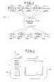
- FIG. 1schematically depicts a stereoscopic panoramic image arrangement for recording, generating and displaying stereoscopic panoramic images, constructed in accordance with the invention
- FIG. 2schematically depicts an exterior plan view of an illustrative stereoscopic data source for use in connection with the arrangement depicted in FIG. 1 ;
- FIG. 3depicts a functional block diagram of the stereoscopic data source depicted in FIG. 2 ;
- FIG. 4depicts a functional block diagram of an illustrative viewing device depicted in FIG. 3 ;
- FIG. 5is useful in understanding the operations performed by the stereoscopic panoramic image arrangement depicted in FIG. 1 in connection with generating a stereoscopic panoramic set;
- FIG. 6is useful in understanding the arrangement for generating and displaying lenticular prints.
- FIGS. 7 through 14depict illustrative image recording arrangements that may be used in connection with the stereoscopic data source described in connection with FIGS. 2 and 3 .
- FIG. 1schematically depicts a stereoscopic panoramic image arrangement 10 for recording, generating and displaying stereoscopic panoramic images, constructed in accordance with the invention.
- the stereoscopic panoramic image arrangement 10includes one or more stereoscopic data sources 11 A through 11 N (generally identified by reference numeral 11 n ) and one or more viewing devices 12 A through 12 M (generally identified by reference numeral 12 m ).
- each stereoscopic data source 11 nrecords images and generates therefrom at least one stereoscopic panoramic image set comprising a set of panoramic images.
- Each stereoscopic data source 11 ncan also transmit respective stereoscopic panoramic image sets that it generates through a distribution channel 13 to one or more of the viewing devices 12 m for viewing, generation of lenticular prints, or other disposition as will be apparent to those skilled in the art.
- the stereoscopic data source 11 nwill include an image recording arrangement, an image processing arrangement and a communication arrangement.
- the image recording arrangementrecords one or more images from which a stereoscopic panoramic image set is generated.
- the image recording arrangementmay be similar to those described in the Peleg I or Peleg II patent applications.
- the image recording arrangementis similar to that described in the Peleg I patent application, or to those described in the Peleg II patent application for which the arrangement is rotated and/or translated to facilitate recording of images from which a panoramic image is generated, at least the image recording arrangement records a series of images as it is rotated around an axis comprising a center of rotation, translated along a path, or any combination of rotation and translation. As the image recording arrangement is rotated and/or translated, it records a series of images from which the image processing arrangement generates at least one set of panoramic images comprising a stereoscopic panoramic image set as described in the Peleg I patent application, or as described below in connection with FIG. 5 .
- the image recording arrangementwill record a series of images.
- the image processing arrangementwill generate the panoramic image by mosaicing together strips from successive ones of the images.
- the strips obtained from the respective imagesmay all have the same displacement from the center of the respective images, as described in the Peleg I patent applications, or they may have different displacements, as described in the Peleg III patent application.
- the panoramic imagesmay be generated as described below in connection with FIG. 5 .
- the image recording arrangementmay be similar to those described in the Peleg II patent application.
- the respective arrangementsmay also be rotated and/or translated to facilitate recording of a series of images from which strips may be mosaiced together to generate a set of panoramic images comprising a stereoscopic panoramic image set.
- the respective arrangementsmay be those including omni-cameras, which arrangements can directly record panoramic images for a stereoscopic panoramic image set without requiring mosaicing.
- the communication arrangementfacilitates transmission of the stereoscopic panoramic image set to the distribution channel 13 for distribution to one or more of the viewing devices 12 m .
- information defining the stereoscopic panoramic image set transferred by the communication arrangementwill be in digital form, and the communication arrangement may include any arrangement that facilitates transfer of digital data between two devices, which may be at the same location or at different locations.
- Illustrative communication arrangementsinclude, for example, a direct connection, such as a wire, cable or optical fiber connection, a wireless connection, any other arrangement for facilitating the transfer of information in digital form, or any combination thereof.
- a direct connectionmay include, for example, a direct network connection, an indirect connection to a network through, for example, a computer, a connection through the public switched telephony network, and the like.
- a wireless connectionmay include, for example, a radio connection, a cellular telephone connection, an infrared connection, and the like
- the viewing devicewill include an a communication arrangement, an image storage arrangement and a display, printer or other device for generating images for viewing by a viewer.
- the viewing device's communication arrangementfacilitates reception of the stereoscopic panoramic image set from the distribution channel 13 .
- information defining the stereoscopic panoramic image set received by the communication arrangementwill be in digital form, and the communication arrangement may include a direct connection, such as a wire, cable or optical fiber connection, a wireless connection, such as a cellular telephone connection, or any other arrangement for facilitating the transfer of information in digital form.
- the image storage arrangementstores the digital information comprising a stereoscopic panoramic image set as received by the viewing device's communication arrangement from the distribution channel 13 for later display.
- the image storage arrangementmay have the capacity to store information comprising only one stereoscopic panoramic image set, or it may have the capacity to store information comprising a plurality of stereoscopic panoramic image sets.
- the displayif provided, will display at least a portion of one or more of the images comprising a stereoscopic panoramic image set. It will be appreciated that, if the display displays at least a portion of one of the images, the image, when viewed, will not be stereoscopic. On the other hand, if the display displays at least a portion of both images using, for example, a lenticular lens, as will be described below in connection with FIG. 6 , the images, when viewed, will be stereoscopic. If a printer is provided, the printer can generate hardcopy prints of one or more of the images comprising a stereoscopic panoramic image set, and may generate, for example, lenticular prints, as will be described below in connection with FIG. 6 , which can be viewed by a viewer using a lenticular lens to provide a stereoscopic image of the scene represented by the stereoscopic panoramic image set.
- each stereoscopic data source 11 n and viewing device 12 mmay also include control arrangements for facilitating control thereof by a respective operator.
- the stereoscopic data source 11 nincludes an image recording arrangement that is to be rotated and/or translated, it can include a control to enable the image recording arrangement to rotate and/or translate.
- the stereoscopic data source 11 ncan include controls to allow an operator to actuate the image recording arrangement to facilitate recording of images of a scene, to enable generation by the image processing arrangement of a stereoscopic panoramic image set for the scene, and to enable the communication arrangement to transmit an stereoscopic panoramic image set to the distribution channel 13 for transfer to one or more of the viewing devices.
- the respective viewing device 12 mcan include a control to facilitate receiving of stereoscopic panoramic image sets from the distribution channel 13 and storage by the image storage arrangement.
- the respective viewing device 12 mcan include a control to facilitate selection of a stereoscopic panoramic image set for display, selection of display mode, and selection of a portion of the stereoscopic panoramic image set to be displayed.
- the viewing device 12 mmay be able to selectively display, as well as at least portions of a stereoscopic panoramic image set, at least portions of individual panoramic images of the stereoscopic panoramic image set as respective display modes, and the selection of the display mode can facilitate display of one or more of the panoramic images of the selected stereoscopic panoramic image set.
- the viewing device 12 mcan include a control to facilitate selection of a respective portion of an stereoscopic panoramic image set that is to be displayed, or the portion of an individual image from the stereoscopic panoramic image set that is to be displayed of the viewing device 12 m provides such display modes.
- a viewing device 12 mcan, instead of or in addition to providing a display for displaying an stereoscopic panoramic image set with a lenticular lens to provide for stereoscopic viewing, provide a printer or similar device for generating a hardcopy print of at least a portion of one or both of the images comprising a stereoscopic panoramic image set, or a hardcopy print of at least a portion of the stereoscopic panoramic image set that, when viewed through a lenticular lens, would provide a stereoscopic panorama.
- a viewing device 12 m that provides a printer or similar devicecan include controls for enabling it to generate such hardcopy prints.
- FIG. 2depicts an exterior plan view of the illustrative stereoscopic data source 11 n
- FIG. 3depicts a functional block diagram of the illustrative stereoscopic data source.
- the illustrative stereoscopic data source 11 nis a portable device that can be, for example, hand-held by an operator, mounted on a vehicle, or the like, and rotated and/or translated to facilitate recording of the series of images from which the stereoscopic panoramic image set is generated.
- the illustrative stereoscopic data source 11 nincludes a housing 20 that houses and supports a video camera 21 , an operator control panel 22 , a display 23 and an antenna 24 .
- the video camera 21provides the image recording arrangement described above
- the operator control panel 22comprises a plurality of controls that may be actuated to enable the video camera 21 to perform predetermined operations.
- the controlscan be implemented in a number of ways, including, for example, pushbuttons that may be depressed by the operator to actuate the respective control.
- the operatorAfter the operator energizes the stereoscopic data source 11 n by actuating a respective control on the operator control panel 22 , he or she can directs the video camera 21 in a particular direction.
- the display 23can display an image indicating what the video camera 21 can record.
- the operatorcan enable the video camera by actuating a control on the operator control panel 22 .
- As the operator actuates the image recording control, and rotates and/or translates the stereoscopic data source 11 nAs the operator actuates the image recording control, and rotates and/or translates the stereoscopic data source 11 n , he or she can enable the video camera 21 to record a series of images from which a stereoscopic panoramic image set can be generated.
- the operatorcan release the image recording control, at which point the video camera 21 can stop recording of images.
- the operatorcan actuate another control on the operator control panel to enable the stereoscopic data source 11 n to generate the panoramic images comprising the stereoscopic panoramic image set.
- the operatorcan actuate another control on the operator control panel 22 to enable the stereoscopic data source 11 n to display at least a portion the generated panoramic image in the display 23 , with the portion being selectable by use of the same or another control on the operator control panel 22 .
- the operatorcan actuate a control on the operator control panel 22 to enable the stereoscopic data source 11 n to display them in a manner so that they can be viewed stereoscopically.
- the stereoscopic data source 11 nmay display the stereoscopic panoramic image set in a manner such that any a number of kinds of appliances may be required to facilitate stereoscopic viewing, including, for example, a lenticular lens, glasses with polarized lenses or lenses of different color, or other appliances as will be appreciated by those skilled in the art, with the stereoscopic data source 11 n displaying the stereoscopic panoramic image set in a corresponding manner.
- the stereoscopic data source 11 ncan transmit them to the distribution channel for distribution to respective ones of the viewing devices 12 m .
- the illustrative stereoscopic data source 11 nmakes use of a cellular telephone connection to transfer information to the distribution channel 13 .
- the operatorcan actuate one or more other controls on the operator control panel 22 to enable the stereoscopic data source 11 n to establish a cellular telephone call to the distribution channel 13 through a cellular provider (not shown). In that case, the stereoscopic data source 11 n can establish a cellular link through the antenna 24 .
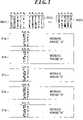
- FIG. 3depicts a functional block diagram of the stereoscopic data source 11 n described above in connection with FIG. 2 .
- the stereoscopic data source 11 nincludes an image capture unit 30 , a local memory unit 31 , a processing unit 32 , one or more local displays 33 A, 33 B, . . . , and a communication unit 34 , as well as the operator control panel 22 .
- the image capture unit 30 , local memory unit 31 and processing unit 32together form the video camera 21 described above in connection with FIG. 2
- the local displays 33 A, 33 B, . . .form the display 23 described above in connection with FIG. 2 .
- the capture unit 30will include, for example, an image sensor, aperture, lenses, and/or the like to facilitate capturing or acquiring of the respective images.
- the image sensormay be any of a number of conventional image sensors, including, for example, CCD (charge coupled devices), film, and the like.
- the processing unitcan control the capture unit 30 , in particular the image sensor, to begin receiving images, and send them to a local display, for example, local display 33 A, for display to the operator.
- a local displayfor example, local display 33 A
- the processing unit 32in addition to sending images from the image sensor to the local display 33 A for display to the operator, will send the images to the local memory unit 31 for storage.
- the processing unit 32will generate the panoramic images comprising the stereoscopic panoramic image set and can display them in the local displays 33 A, 33 B, . . . .
- the processing unit 32when the operator actuates the stereoscopic panoramic image set transmission control on the operator control panel 22 , the processing unit 32 enables the panoramic images comprising the stereoscopic panoramic image set to be transmitted through the communication unit 34 to the distribution channel 13 .
- the processing unit 32can initiate a cellular telephone call to the distribution channel 13 and, after the distribution channel 13 responds, cooperate with the distribution channel 13 to facilitate transmission of the stereoscopic panoramic image set to the distribution channel 13 .
- the processing unit 32can use a predetermined telephone number in initiating the cellular telephone call, or it can make use of a telephone number provided by the operator through the operator control panel 22 . Accordingly, the operator control panel 22 can include a numeric keypad that the operator can use to provide the telephone number. It will be appreciated that the processing unit 32 , prior to transferring the information comprising the stereoscopic panoramic image set, can also encode the information using any of a plurality of encoding or compression algorithms, such as the well known JPEG or GIF algorithms, which can facilitate a reduction of the time that might be required to transfer the information.
- FIG. 4depicts a functional block diagram of an illustrative viewing device 12 m constructed in accordance with the invention.
- the illustrative viewing device 12 mincludes a receiver 40 , a decoder 41 , a display unit 42 and a direction control unit 43 .
- the receiver 40is provided to receive information defining the panoramic images comprising a stereoscopic panoramic image set from the distribution channel 13 .
- the receiver 40provides the information to the decoder 41 for decoding.
- the decoder 41After the decoder 41 has decoded the digital information, it can provide it to the display unit 42 for display to the operator.
- the display unit 42includes a display device for displaying images to a viewer and may also include sufficient memory for storing panoramic images comprising one or more stereoscopic panoramic image sets. If the display unit 42 does include sufficient memory for storing panoramic images comprising a plurality of stereoscopic panoramic image sets, the viewing device 12 m can also include a control that allows an operator to select a stereoscopic panoramic image set for display. If the display unit 42 is unable to display the entire stereoscopic panoramic image set at one time, the direction control unit 43 can allow a viewer to select a portion of the stereoscopic panoramic image set to be displayed.
- the display unit 42preferably displays the stereoscopic panoramic image set in a stereoscopic manner.
- the display unit 42may display respective images of the stereoscopic panoramic image set in separate left and right displays, each of which can be viewed by a respective one of the viewer's eyes.
- a binocular devicemay be provided having respective ocular devices to that displays a respective image, or portion thereof, to a respective one of the eyes of the viewer.
- the display unit 42may display the panoramic images such that, when viewed using any of a number of kinds of appliances used facilitate stereoscopic viewing, including, for example, a lenticular lens, glasses with polarized lenses or lenses of different color, or other appliances as will be appreciated by those skilled in the art, the images will be viewed stereoscopically.
- appliancesused facilitate stereoscopic viewing, including, for example, a lenticular lens, glasses with polarized lenses or lenses of different color, or other appliances as will be appreciated by those skilled in the art, the images will be viewed stereoscopically.
- two panoramic images comprising a stereoscopic panoramic image setcan be generated using two strips from each of a series of images recorded by the stereoscopic data source 11 n .
- a stereoscopic panoramic image setcomprising a plurality of panoramic images, may be generated that, when the panoramic images are viewed in sets, will provide a stereoscopic image. This will be described in connection with FIG. 5 .
- FIG. 5depicts a series of successive image 50 ( 1 ), 50 ( 2 ), . . .
- a plurality of panoramic images 51 a , 51 b . . . comprising a stereoscopic panoramic image setare generated using respective strips a 1 , a 2 , . . . a 3 , b 1 , b 2 , . . . b 3 , . . . from the respective images 50 ( i ). Strips a 1 , a 2 , . . .
- the display 23 , 33 A, 33 B (stereoscopic data source 11 n ) and display 42 (viewing device 12 m )can display panoramic images comprising a stereoscopic panoramic image set using a lenticular lens, which can provide a stereoscopic image.
- the lenticular lens 61includes a flat rear surface and a curved forward surface. The panoramic images from a stereoscopic panoramic image set are projected, in segments, at the flat rear surface of the lenticular lens, and the viewer views the stereoscopic image by looking towards the forward surface.
- each segment 61 ( s )is depicted 61 ( 1 ) through 61 ( 3 ) (generally identified by reference numeral 61 ( s )), each of which is associated with a curved forward surface.
- Each segment 61 ( s )is provided with a respective segment of each of the panoramic images, identified by reference numeral 62 ( s )(A), 62 ( s )(B), 62 ( s )(C) (generally identified by reference numeral 62 ( s )( p ), where index “p” refers to the respective panoramic image.
- index “p”refers to the respective panoramic image.
- the viewercan selectively view one of the three images 63 A, 63 B, 63 C (generally identified by reference numeral 63 p ).
- the three images 63 A, 63 B, 63 Cgenerally identified by reference numeral 63 p .
- a viewerviews the lenticular lens 61 from the right (from above, as shown in FIG. 6 )
- he or shecan view the image comprising segments 62 ( s )(C).
- a viewerviews the lenticular lens from the left (from below as shown in FIG. 6 )
- he or shecan view the image comprising segments 62 ( s )(A).
- a viewerviews the lenticular lens from directly on, he or she can view the image comprising segments 62 ( s )(B). If, for example the viewer views the lenticular lens such that the left eye views the lens from the right and the left eye views the lens from the left, and if the panoramic image used for segments 62 ( s )(A) is the left panoramic image of the stereoscopic panoramic image set and the panoramic image used for segments 62 ( s )(C) is the right panoramic image of the same stereoscopic panoramic image set, the viewer will view the image stereoscopically.
- the image recording arrangementwhich includes the video camera 21 of the illustrative stereoscopic data source 11 n , maybe similar to those described in the Peleg I or Peleg II patent applications.
- the center of rotation of the camerawill preferably be to the rear of the camera's center of projection to provide that strips obtained from each images will be from a different viewing direction, thereby to facilitate generation of respective panoramic images for the stereoscopic panoramic image set.
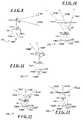
- FIGS. 7 through 14depict image recording arrangements 100 , 110 and 120 that make use of fixed or rotating mirrors or mirror segments
- FIGS. 10 through 12depict image recording arrangements 130 , 140 , 150 that make use of fixed or rotating prisms or prism segment, respectively
- FIG. 13depicts an image recording arrangement 160 that makes use of a lens
- Each image recording arrangement 100 , 110 , 120 , 130 , 140 , 150 , 160includes a respective camera 101 , 111 , 121 , 131 , 141 , 151 , 161 , which may be a still or video camera.
- Image recording arrangement 170makes use of a plurality of cameras, which may be still or video cameras.
- FIG. 7schematically depicts an image recording arrangement 100 including a camera 101 and a mirror 102 that is oriented at a fixed angle with respect to the camera's axis 103 .
- the angleis selected so as to be between zero and ninety degrees to facilitate reflecting rays 104 A through 104 C toward the camera's image sensor 105 .
- the rays 104 A, 104 B and 104 C(generally identified by reference numeral 104 ) as directed toward the image recording arrangement from a scene (not shown) are reflected off the mirror 102 and directed to regions 106 A, 106 B and 106 C, respectively to facilitate recording of an image of the scene.
- FIG. 7that FIG. schematically depicts an image recording arrangement 100 including a camera 101 and a mirror 102 that is oriented at a fixed angle with respect to the camera's axis 103 .
- the angleis selected so as to be between zero and ninety degrees to facilitate reflecting rays 104 A through 104 C toward the camera's image sensor
- the rays 104 A, 104 B and 104 Crepresent respective viewing directions. Strips including the respective regions can be used in generating respective images for an stereoscopic panoramic image set as described above.
- the mirror 102serves to relocate the apparent center of projection for the rays 104 from a point O in the optical system 107 of the camera 101 to a point O′ well ahead of the camera 101 and the rear of the mirror 102 . This will allow the camera 101 to be rotated around a center of rotation that passes through the camera 102 , and that can even pass through the camera's center of projection O.
- FIG. 8that FIG. schematically depicts an image recording arrangement 110 including a camera 111 and a mirror 112 that can be oriented at a plurality of angular orientations with respect to the camera's axis 113 .
- the anglesare selected so as to be between zero and ninety degrees to facilitate reflecting rays 114 A and 114 B toward the center of the camera's image sensor 115 .
- the rays 114 A and 114 B(generally identified by reference numeral 114 ) as directed toward the image recording arrangement from a scene (not shown) are reflected off the mirror 112 and directed to the same region toward the center of the image sensor 115 , with images 16 A, 16 B, . . .
- the rays 114 A and 114 Brepresent respective viewing directions.
- the camera 111records respective images for each of the angular positions at which the mirror 112 is oriented to facilitate recording of respective images of the scene. Strips including the respective regions can be used in generating respective images for an stereoscopic panoramic image set as described above.
- the mirror 112serves to relocate the apparent center of projection for the rays 114 from a point O in the optical system 117 of the camera 111 to a point O′ that conforms to the center of rotation of the mirror 112 . As with camera 101 , this will allow the camera 111 to be rotated around a center of rotation that passes through the camera 111 , and that can even pass through the camera's center of projection O.
- FIG. 9that FIG. schematically depicts an image recording arrangement 120 including a camera 121 and respective mirror segments 122 A, 122 B that are positioned on opposite sides of the camera's axis 123 and oriented at complementary fixed angles with respect thereto. The angles is selected so as to be between zero and ninety degrees to facilitate reflecting rays 124 A and 124 B toward the camera's image sensor 125 .
- the rays 124 A and 124 B(generally identified by reference numeral 124 ) as directed toward the image recording arrangement from a scene (not shown) are reflected off the mirror segments 122 A, 122 B and directed to regions 126 A and 126 B, respectively to facilitate recording of an image of the scene.
- a ray 124 B in the gapwill be directed to a region 126 B between regions 126 A and 126 C.
- the rays 124 , 124 B and 124 Crepresent respective viewing directions. Strips including the respective regions can be used in generating respective images for an stereoscopic panoramic image set as described above.
- the mirror segments 122 A, 122 Bjointly serve to relocate the apparent center of projection for the rays 104 from a point O in the optical system 127 of the camera 121 to a point O′ ahead of the camera 101 and between the mirror segments 122 A, 122 B. This will allow the camera 121 to be rotated around a center of rotation that passes through the camera 121 , and that can even pass through the camera's center of projection O.
- FIGS. 10 and 12schematically depict image recording arrangements 130 , 150 that are similar to respective image recording arrangement 100 , 120 described above in connection with FIG. 7 , 9 except that, instead of using mirrors, the respective image recording arrangement 130 , 150 includes a respective prism 132 (in the case of FIG. 10 ), or prism segments 152 (in the case of FIG. 12 ), with prism 132 , and prism segments 152 A, 152 C, being disposed at a fixed angle with respect to the camera's axis 134 , 154 .
- the rays 134 A, 134 B and 134 C(generally identified by reference numeral 134 ) directed toward the image recording arrangement from a scene (not shown) are refracted by the prism 132 and directed to regions 136 A, 136 B and 136 C, respectively to facilitate recording of an image of the scene, and strips including the respective regions can be used in generating respective images for an stereoscopic panoramic image set as described above.
- the rays 154 A, 154 B and 154 C(generally identified by reference numeral 154 ) as directed toward the image recording arrangement from a scene (not shown) are refracted by off the prism segments 152 A, 152 C and directed to regions 156 A and 156 C, respectively to facilitate recording of an image of the scene. If, as is the case in connection with arrangement 150 , there is a gap between the prism segments 152 A and 152 C, a ray 154 B in the gap will be directed to a region 156 B between regions 156 A and 156 C. As shown in FIG. 9 , the rays 134 , 134 B and 134 C ( FIG.
- the prism 132 and prism segments 152serve to relocate the apparent center of projection for the rays 134 , 154 from a point O in the optical system 137 , 157 of the camera 131 , 151 to a point O′ that conforms to the center of projection of the respective camera. As with cameras 101 , 121 , this will allow the camera 131 , 151 to be rotated around a center of rotation that passes through the camera 131 , 151 and that can even pass through the camera's center of projection O.
- FIG. 11schematically depicts image recording arrangement 140 that is similar to respective image recording arrangement 110 described above in connection with FIG. 8 , except that, instead of using mirrors, the image recording arrangement 140 includes a prism 142 , which can be disposed a plurality of respective angles with respect to the camera's axis 144 .
- the rays 144 A, 144 B, . . .(generally identified by reference numeral 144 ) directed toward the image recording arrangement from a scene (not shown) are refracted by the prism 142 and directed toward a region toward the center of the image sensor 145 ; the camera 141 records respective images 146 A, 146 B, . . .
- the rays 144 A, 144 B, . . .represent respective viewing directions.
- the prism 142serves to relocate the apparent center of projection for the rays 144 from a point O in the optical system 147 of the camera 141 to a point O′ that conforms to the center of rotation of the respective camera. As with camera 111 , this will allow the camera 141 to be rotated around a center of rotation that passes through the camera 141 and that can even pass through the camera's center of projection O.
- FIG. 13schematically depicts an image recording arrangement 160 that is similar to image recording arrangements 120 and 150 described above in connection with FIGS. 9 and 12 , except that, instead of using mirror segments or prism segments, the image recording arrangements 160 includes a lens 162 .
- the rays 164 A, 164 B and 164 C(generally identified by reference numeral 164 ) directed toward the image recording arrangement from a scene (not shown) are refracted by the lens and directed to regions 166 A, 166 B and 166 C, respectively to facilitate recording of an image of the scene, and strips including the respective regions can be used in generating respective images for a stereoscopic panoramic image set as described above.
- FIG. 13schematically depicts an image recording arrangement 160 that is similar to image recording arrangements 120 and 150 described above in connection with FIGS. 9 and 12 , except that, instead of using mirror segments or prism segments, the image recording arrangements 160 includes a lens 162 .
- the rays 164 A, 164 B and 164 C(generally identified by reference numeral
- the rays 164 , 164 B and 164 Crepresent respective viewing directions.
- the lens 162serves to relocate the apparent center of projection for the rays 164 from a point O in the optical system 167 of the camera 161 to a point O′ that conforms to the center of rotation of the camera 161 . As with cameras 121 , 151 , this will allow the camera 161 to be rotated around a center of rotation that passes through the camera 161 and that can even pass through the camera's center of projection O.
- FIG. 14depicts an arrangement 170 that makes use of a plurality of cameras 171 A . . . 171 K (generally identified by reference numeral 171 k ) mounted linearly on a platform 172 .
- the arrangement 170when the arrangement 170 is pointed in a particular direction to facilitate recording of respective images by the cameras 171 k , in the images recorded by the cameras 171 k , strips in the “K” respective images as recorded by the respective cameras will be from different viewing directions.
- the cameras 171 kare enabled to record a series of images as described above.
- respective strips the series of images recorded by each respective camera 171 k′ , 171 k′′ , . . .may be mosaiced together to form a respective panoramic image.
- the inventionprovides a number of advantages.
- the inventionprovides an arrangement, including a stereoscopic data source for recording images of a scene for use in generating a stereoscopic image set and a viewing device for displaying the stereoscopic image set to provide stereoscopic views of the scene, generating prints, and the like.
- the stereoscopic data sourcemay record a series of images from which the stereoscopic panoramic image set may be generated. After the stereoscopic data source has recorded the series of images, it can transmit them to the distribution channel 13 for distribution to one or more viewing devices.
- the distribution channel 13 or viewing devicesmay themselves generate the images comprising stereoscopic image set.
- the distribution channel and/or one or more viewing deviceswill include the components for generating the stereoscopic panoramic image set, which were described above as comprising part of the stereoscopic data source.
- the cameras described above in connection with FIGS. 7 through 14have been described as comprising conventional still or video cameras, it will be appreciated that they may comprise cameras in which image recording elements are provided only in the portions of the respective image planes from which strips will be obtained for use in generating the respective images of the stereoscopic image set.
- segments of respective images from a stereoscopic panoramic image setare displayed and viewed through a lenticular lens
- theymay instead be printed and viewed through a lenticular lens, printed directly on the rear of the lenticular lens, or other arrangements as will be apparent to those skilled in the art.
- the imagesare printed on the rear of the lenticular lens, it will be appreciated that the lenticular curved forward surface may be formed before, during or after the images are printed.
- the strips for each panoramic image of the stereoscopic panoramic image setare indicated as being from the same horizontal displacement in the successive images, it will be appreciated that they may be from different horizontal displacements as described in the Peleg III patent application. This may be useful in connection with to accommodate adjustment of disparity if desired to accommodate stereoscopic depth.
- a system in accordance with the inventioncan be constructed in whole or in part from special purpose hardware or a general purpose computer system, or any combination thereof , any portion of which may be controlled by a suitable program.
- Any programmay be composed of instructions encoded in a computer-readable medium that may in whole or in part comprise part of or be stored on the system in a conventional manner, or it may in whole or in part be provided in to the system over a network or other mechanism for transferring information in a conventional manner.
- the systemmay be operated and/or otherwise controlled by means of information provided by an operator using operator input elements (not shown) which may be connected directly to the system or which may transfer the information to the system over a network or other mechanism for transferring information in a conventional manner.
Landscapes
- Engineering & Computer Science (AREA)
- Multimedia (AREA)
- Signal Processing (AREA)
- Testing, Inspecting, Measuring Of Stereoscopic Televisions And Televisions (AREA)
- Stereoscopic And Panoramic Photography (AREA)
Abstract
Description
Claims (55)
Priority Applications (1)
| Application Number | Priority Date | Filing Date | Title |
|---|---|---|---|
| US09/861,859US7477284B2 (en) | 1999-09-16 | 2001-04-19 | System and method for capturing and viewing stereoscopic panoramic images |
Applications Claiming Priority (7)
| Application Number | Priority Date | Filing Date | Title |
|---|---|---|---|
| US09/396,248US6665003B1 (en) | 1998-09-17 | 1999-09-16 | System and method for generating and displaying panoramic images and movies |
| US19838100P | 2000-04-19 | 2000-04-19 | |
| US21715900P | 2000-07-06 | 2000-07-06 | |
| US23056200P | 2000-08-30 | 2000-08-30 | |
| US09/726,198US6795109B2 (en) | 1999-09-16 | 2000-11-29 | Stereo panoramic camera arrangements for recording panoramic images useful in a stereo panoramic image pair |
| US09/792,638US6831677B2 (en) | 2000-02-24 | 2001-02-24 | System and method for facilitating the adjustment of disparity in a stereoscopic panoramic image pair |
| US09/861,859US7477284B2 (en) | 1999-09-16 | 2001-04-19 | System and method for capturing and viewing stereoscopic panoramic images |
Related Parent Applications (3)
| Application Number | Title | Priority Date | Filing Date |
|---|---|---|---|
| US09/396,248Continuation-In-PartUS6665003B1 (en) | 1998-09-17 | 1999-09-16 | System and method for generating and displaying panoramic images and movies |
| US09/726,198Continuation-In-PartUS6795109B2 (en) | 1999-09-16 | 2000-11-29 | Stereo panoramic camera arrangements for recording panoramic images useful in a stereo panoramic image pair |
| US09/792,638Continuation-In-PartUS6831677B2 (en) | 1999-09-16 | 2001-02-24 | System and method for facilitating the adjustment of disparity in a stereoscopic panoramic image pair |
Publications (3)
| Publication Number | Publication Date |
|---|---|
| US20040223051A1 US20040223051A1 (en) | 2004-11-11 |
| US20050157166A9 US20050157166A9 (en) | 2005-07-21 |
| US7477284B2true US7477284B2 (en) | 2009-01-13 |
Family
ID=34754032
Family Applications (1)
| Application Number | Title | Priority Date | Filing Date |
|---|---|---|---|
| US09/861,859Expired - Fee RelatedUS7477284B2 (en) | 1999-09-16 | 2001-04-19 | System and method for capturing and viewing stereoscopic panoramic images |
Country Status (1)
| Country | Link |
|---|---|
| US (1) | US7477284B2 (en) |
Cited By (14)
| Publication number | Priority date | Publication date | Assignee | Title |
|---|---|---|---|---|
| US20050041156A1 (en)* | 2002-04-25 | 2005-02-24 | Tetsujiro Kondo | Image processing apparatus, image processing method, and image processing program |
| US20070014347A1 (en)* | 2005-04-07 | 2007-01-18 | Prechtl Eric F | Stereoscopic wide field of view imaging system |
| US20080007617A1 (en)* | 2006-05-11 | 2008-01-10 | Ritchey Kurtis J | Volumetric panoramic sensor systems |
| US20080024594A1 (en)* | 2004-05-19 | 2008-01-31 | Ritchey Kurtis J | Panoramic image-based virtual reality/telepresence audio-visual system and method |
| US20080062254A1 (en)* | 2000-03-06 | 2008-03-13 | Edwards Eric D | System and method for capturing adjacent images by utilizing a panorama mode |
| US20080117287A1 (en)* | 2006-11-16 | 2008-05-22 | Park Michael C | Distributed video sensor panoramic imaging system |
| US20080207261A1 (en)* | 2006-11-30 | 2008-08-28 | Paten Navigation Inc. | Panoramic scene capture using a mobile wireless device |
| US20090080092A1 (en)* | 2007-09-23 | 2009-03-26 | Rafael Advanced Defense Systems Ltd. | System for increasing horizontal field of view of a camera |
| US20090262180A1 (en)* | 2008-04-18 | 2009-10-22 | Samsung Electronics Co., Ltd. | Apparatus for generating panoramic images and method thereof |
| US20100194861A1 (en)* | 2009-01-30 | 2010-08-05 | Reuben Hoppenstein | Advance in Transmission and Display of Multi-Dimensional Images for Digital Monitors and Television Receivers using a virtual lens |
| US20130250040A1 (en)* | 2012-03-23 | 2013-09-26 | Broadcom Corporation | Capturing and Displaying Stereoscopic Panoramic Images |
| US8723920B1 (en) | 2011-07-05 | 2014-05-13 | 3-D Virtual Lens Technologies, Llc | Encoding process for multidimensional display |
| US10474414B2 (en) | 2015-08-17 | 2019-11-12 | Ricoh Company, Ltd. | Image display system, information processing apparatus, and image display method |
| US20210144360A1 (en)* | 2018-07-30 | 2021-05-13 | Huawei Technologies Co., Ltd. | Multifocal display devices and methods |
Families Citing this family (17)
| Publication number | Priority date | Publication date | Assignee | Title |
|---|---|---|---|---|
| US7999842B1 (en)* | 2004-05-28 | 2011-08-16 | Ricoh Co., Ltd. | Continuously rotating video camera, method and user interface for using the same |
| US7852370B2 (en)* | 2004-11-05 | 2010-12-14 | Yissum Research Development Company Of The Hebrew University Of Jerusalem | Method and system for spatio-temporal video warping |
| EP1815694A1 (en)* | 2004-11-27 | 2007-08-08 | Bracco Imaging S.P.A. | Systems and methods for displaying multiple views of a single 3d rendering ("multiple views") |
| KR100649523B1 (en)* | 2005-06-30 | 2006-11-27 | 삼성에스디아이 주식회사 | Stereoscopic video display |
| CN100501566C (en)* | 2006-01-05 | 2009-06-17 | 李明 | Curved surface movie projection system and method |
| KR100823264B1 (en)* | 2006-04-13 | 2008-04-17 | 삼성전자주식회사 | Method and apparatus for requesting printing of panoramic image from mobile device |
| US8866920B2 (en)* | 2008-05-20 | 2014-10-21 | Pelican Imaging Corporation | Capturing and processing of images using monolithic camera array with heterogeneous imagers |
| FR2946438B1 (en)* | 2009-06-08 | 2014-11-07 | Erwan Devigon | SYSTEM AND METHOD FOR STEREOSCOPIC IMAGE GENERATION WITH PARAMETRABLE DISTRIBUTION IN A SYSTEM AND METHOD FOR SHOOTING APPARATUS (N> 1) |
| JP2011082919A (en)* | 2009-10-09 | 2011-04-21 | Sony Corp | Image processing device and method, and program |
| US10080006B2 (en) | 2009-12-11 | 2018-09-18 | Fotonation Limited | Stereoscopic (3D) panorama creation on handheld device |
| US8878950B2 (en) | 2010-12-14 | 2014-11-04 | Pelican Imaging Corporation | Systems and methods for synthesizing high resolution images using super-resolution processes |
| CN104081414B (en) | 2011-09-28 | 2017-08-01 | Fotonation开曼有限公司 | Systems and methods for encoding and decoding light field image files |
| KR101804205B1 (en)* | 2012-03-15 | 2017-12-04 | 삼성전자주식회사 | Apparatus and method for image processing |
| PL4296963T3 (en) | 2012-08-21 | 2025-04-28 | Adeia Imaging Llc | Method for depth detection in images captured using array cameras |
| CN107111928B (en) | 2014-11-17 | 2020-07-31 | 洋马动力科技有限公司 | Display system for remote control work machine |
| US10311636B1 (en)* | 2016-07-29 | 2019-06-04 | EVOX Productions, LLC | Layered panoramas for virtual reality (VR) |
| US10740969B2 (en)* | 2015-12-21 | 2020-08-11 | EVOX Productions, LLC | Layered panoramas for virtual reality (VR) |
Citations (39)
| Publication number | Priority date | Publication date | Assignee | Title |
|---|---|---|---|---|
| US4134644A (en) | 1977-01-10 | 1979-01-16 | Marks Alvin M | 3D Color pictures with multichrome filters |
| EP0361297A1 (en) | 1988-09-20 | 1990-04-04 | Nec Corporation | Image pickup system capable of obtaining a plurality of stereo images with different base height ratios |
| US5455689A (en)* | 1991-06-27 | 1995-10-03 | Eastman Kodak Company | Electronically interpolated integral photography system |
| US5594498A (en)* | 1994-10-14 | 1997-01-14 | Semco, Inc. | Personal audio/video surveillance system |
| US5649032A (en)* | 1994-11-14 | 1997-07-15 | David Sarnoff Research Center, Inc. | System for automatically aligning images to form a mosaic image |
| US5657073A (en) | 1995-06-01 | 1997-08-12 | Panoramic Viewing Systems, Inc. | Seamless multi-camera panoramic imaging with distortion correction and selectable field of view |
| US5721585A (en) | 1996-08-08 | 1998-02-24 | Keast; Jeffrey D. | Digital video panoramic image capture and display system |
| US5764871A (en)* | 1993-10-21 | 1998-06-09 | Eastman Kodak Company | Method and apparatus for constructing intermediate images for a depth image from stereo images using velocity vector fields |
| WO1998034195A1 (en)* | 1997-01-30 | 1998-08-06 | Yissum Research Development Company Of The Hebrew University Of Jerusalem | Generalized panoramic mosaic |
| US5825466A (en) | 1996-01-18 | 1998-10-20 | Image Technology International, Inc. | 3D photo printer with image distortion correction |
| WO1999017555A1 (en) | 1997-10-01 | 1999-04-08 | The Nottingham Trent University | 3d imaging with line-scanning |
| WO1999018725A1 (en) | 1997-10-08 | 1999-04-15 | Interactive Pictures Corporation (Ipix) | Method and system for the creation and interactive viewing of totally immersive stereoscopic images |
| JPH11146425A (en) | 1997-11-11 | 1999-05-28 | Canon Inc | Compound-eye camera, compound-eye camera system, and compound-eye camera control method |
| JPH11164326A (en) | 1997-11-26 | 1999-06-18 | Oki Electric Ind Co Ltd | Panorama stereo image generation display method and recording medium recording its program |
| US5963664A (en)* | 1995-06-22 | 1999-10-05 | Sarnoff Corporation | Method and system for image combination using a parallax-based technique |
| US5986668A (en)* | 1997-08-01 | 1999-11-16 | Microsoft Corporation | Deghosting method and apparatus for construction of image mosaics |
| EP0989436A2 (en) | 1998-08-28 | 2000-03-29 | Lucent Technologies Inc. | Stereoscopic panoramic viewing system |
| US6075905A (en)* | 1996-07-17 | 2000-06-13 | Sarnoff Corporation | Method and apparatus for mosaic image construction |
| US6078701A (en)* | 1997-08-01 | 2000-06-20 | Sarnoff Corporation | Method and apparatus for performing local to global multiframe alignment to construct mosaic images |
| US6083353A (en)* | 1996-09-06 | 2000-07-04 | University Of Florida | Handheld portable digital geographic data manager |
| US20010010546A1 (en)* | 1997-09-26 | 2001-08-02 | Shenchang Eric Chen | Virtual reality camera |
| US6275206B1 (en)* | 1999-03-17 | 2001-08-14 | Intel Corporation | Block mapping based up-sampling method and apparatus for converting color images |
| US6278480B1 (en)* | 1997-02-07 | 2001-08-21 | Canon Kabushiki Kaisha | Compound eye camera system |
| US20010020976A1 (en) | 1999-09-16 | 2001-09-13 | Shmuel Peleg | Stereo panoramic camera arrangements for recording panoramic images useful in a stereo panoramic image pair |
| US20010038413A1 (en) | 2000-02-24 | 2001-11-08 | Shmuel Peleg | System and method for facilitating the adjustment of disparity in a stereoscopic panoramic image pair |
| US20010043264A1 (en)* | 1997-08-13 | 2001-11-22 | Michael J. Sinclair | Panoramic digital camera system and method |
| US6377294B2 (en)* | 1997-06-13 | 2002-04-23 | Olympus Optical Co., Ltd. | Electronic photographing device |
| US6434280B1 (en)* | 1997-11-10 | 2002-08-13 | Gentech Corporation | System and method for generating super-resolution-enhanced mosaic images |
| US6435969B1 (en)* | 1998-11-03 | 2002-08-20 | Nintendo Co., Ltd. | Portable game machine having image capture, manipulation and incorporation |
| US6512892B1 (en)* | 1999-09-15 | 2003-01-28 | Sharp Kabushiki Kaisha | 3D camera |
| US6522787B1 (en)* | 1995-07-10 | 2003-02-18 | Sarnoff Corporation | Method and system for rendering and combining images to form a synthesized view of a scene containing image information from a second image |
| US6532298B1 (en)* | 1998-11-25 | 2003-03-11 | Iridian Technologies, Inc. | Portable authentication device and method using iris patterns |
| US6535650B1 (en)* | 1998-07-21 | 2003-03-18 | Intel Corporation | Creating high resolution images |
| US6643413B1 (en)* | 2000-03-27 | 2003-11-04 | Microsoft Corporation | Manifold mosaic hopping for image-based rendering |
| US6665003B1 (en)* | 1998-09-17 | 2003-12-16 | Issum Research Development Company Of The Hebrew University Of Jerusalem | System and method for generating and displaying panoramic images and movies |
| US6717608B1 (en)* | 1999-12-31 | 2004-04-06 | Stmicroelectronics, Inc. | Motion estimation for panoramic digital camera |
| US6750860B1 (en)* | 1998-12-28 | 2004-06-15 | Microsoft Corporation | Rendering with concentric mosaics |
| US6850210B1 (en)* | 1998-11-12 | 2005-02-01 | Stereographics Corporation | Parallax panoramagram having improved depth and sharpness |
| US6956573B1 (en)* | 1996-11-15 | 2005-10-18 | Sarnoff Corporation | Method and apparatus for efficiently representing storing and accessing video information |
- 2001
- 2001-04-19USUS09/861,859patent/US7477284B2/ennot_activeExpired - Fee Related
Patent Citations (43)
| Publication number | Priority date | Publication date | Assignee | Title |
|---|---|---|---|---|
| US4134644A (en) | 1977-01-10 | 1979-01-16 | Marks Alvin M | 3D Color pictures with multichrome filters |
| EP0361297A1 (en) | 1988-09-20 | 1990-04-04 | Nec Corporation | Image pickup system capable of obtaining a plurality of stereo images with different base height ratios |
| US5455689A (en)* | 1991-06-27 | 1995-10-03 | Eastman Kodak Company | Electronically interpolated integral photography system |
| US5764871A (en)* | 1993-10-21 | 1998-06-09 | Eastman Kodak Company | Method and apparatus for constructing intermediate images for a depth image from stereo images using velocity vector fields |
| US5594498A (en)* | 1994-10-14 | 1997-01-14 | Semco, Inc. | Personal audio/video surveillance system |
| US5649032A (en)* | 1994-11-14 | 1997-07-15 | David Sarnoff Research Center, Inc. | System for automatically aligning images to form a mosaic image |
| US5991444A (en)* | 1994-11-14 | 1999-11-23 | Sarnoff Corporation | Method and apparatus for performing mosaic based image compression |
| US5657073A (en) | 1995-06-01 | 1997-08-12 | Panoramic Viewing Systems, Inc. | Seamless multi-camera panoramic imaging with distortion correction and selectable field of view |
| US5963664A (en)* | 1995-06-22 | 1999-10-05 | Sarnoff Corporation | Method and system for image combination using a parallax-based technique |
| US6522787B1 (en)* | 1995-07-10 | 2003-02-18 | Sarnoff Corporation | Method and system for rendering and combining images to form a synthesized view of a scene containing image information from a second image |
| US5825466A (en) | 1996-01-18 | 1998-10-20 | Image Technology International, Inc. | 3D photo printer with image distortion correction |
| US6075905A (en)* | 1996-07-17 | 2000-06-13 | Sarnoff Corporation | Method and apparatus for mosaic image construction |
| US5721585A (en) | 1996-08-08 | 1998-02-24 | Keast; Jeffrey D. | Digital video panoramic image capture and display system |
| US6083353A (en)* | 1996-09-06 | 2000-07-04 | University Of Florida | Handheld portable digital geographic data manager |
| US6956573B1 (en)* | 1996-11-15 | 2005-10-18 | Sarnoff Corporation | Method and apparatus for efficiently representing storing and accessing video information |
| US6532036B1 (en)* | 1997-01-30 | 2003-03-11 | Yissum Research Development Company Of The Hebrew University Of Jerusalem | Generalized panoramic mosaic |
| WO1998034195A1 (en)* | 1997-01-30 | 1998-08-06 | Yissum Research Development Company Of The Hebrew University Of Jerusalem | Generalized panoramic mosaic |
| US6278480B1 (en)* | 1997-02-07 | 2001-08-21 | Canon Kabushiki Kaisha | Compound eye camera system |
| US6377294B2 (en)* | 1997-06-13 | 2002-04-23 | Olympus Optical Co., Ltd. | Electronic photographing device |
| US5986668A (en)* | 1997-08-01 | 1999-11-16 | Microsoft Corporation | Deghosting method and apparatus for construction of image mosaics |
| US6078701A (en)* | 1997-08-01 | 2000-06-20 | Sarnoff Corporation | Method and apparatus for performing local to global multiframe alignment to construct mosaic images |
| US20010043264A1 (en)* | 1997-08-13 | 2001-11-22 | Michael J. Sinclair | Panoramic digital camera system and method |
| US20010010546A1 (en)* | 1997-09-26 | 2001-08-02 | Shenchang Eric Chen | Virtual reality camera |
| WO1999017555A1 (en) | 1997-10-01 | 1999-04-08 | The Nottingham Trent University | 3d imaging with line-scanning |
| WO1999018725A1 (en) | 1997-10-08 | 1999-04-15 | Interactive Pictures Corporation (Ipix) | Method and system for the creation and interactive viewing of totally immersive stereoscopic images |
| US6434280B1 (en)* | 1997-11-10 | 2002-08-13 | Gentech Corporation | System and method for generating super-resolution-enhanced mosaic images |
| JPH11146425A (en) | 1997-11-11 | 1999-05-28 | Canon Inc | Compound-eye camera, compound-eye camera system, and compound-eye camera control method |
| JPH11164326A (en) | 1997-11-26 | 1999-06-18 | Oki Electric Ind Co Ltd | Panorama stereo image generation display method and recording medium recording its program |
| US6535650B1 (en)* | 1998-07-21 | 2003-03-18 | Intel Corporation | Creating high resolution images |
| EP0989436A2 (en) | 1998-08-28 | 2000-03-29 | Lucent Technologies Inc. | Stereoscopic panoramic viewing system |
| US6141145A (en) | 1998-08-28 | 2000-10-31 | Lucent Technologies | Stereo panoramic viewing system |
| US6665003B1 (en)* | 1998-09-17 | 2003-12-16 | Issum Research Development Company Of The Hebrew University Of Jerusalem | System and method for generating and displaying panoramic images and movies |
| US6435969B1 (en)* | 1998-11-03 | 2002-08-20 | Nintendo Co., Ltd. | Portable game machine having image capture, manipulation and incorporation |
| US6850210B1 (en)* | 1998-11-12 | 2005-02-01 | Stereographics Corporation | Parallax panoramagram having improved depth and sharpness |
| US6532298B1 (en)* | 1998-11-25 | 2003-03-11 | Iridian Technologies, Inc. | Portable authentication device and method using iris patterns |
| US6750860B1 (en)* | 1998-12-28 | 2004-06-15 | Microsoft Corporation | Rendering with concentric mosaics |
| US6275206B1 (en)* | 1999-03-17 | 2001-08-14 | Intel Corporation | Block mapping based up-sampling method and apparatus for converting color images |
| US6512892B1 (en)* | 1999-09-15 | 2003-01-28 | Sharp Kabushiki Kaisha | 3D camera |
| US20010020976A1 (en) | 1999-09-16 | 2001-09-13 | Shmuel Peleg | Stereo panoramic camera arrangements for recording panoramic images useful in a stereo panoramic image pair |
| US6717608B1 (en)* | 1999-12-31 | 2004-04-06 | Stmicroelectronics, Inc. | Motion estimation for panoramic digital camera |
| US20010038413A1 (en) | 2000-02-24 | 2001-11-08 | Shmuel Peleg | System and method for facilitating the adjustment of disparity in a stereoscopic panoramic image pair |
| US6831677B2 (en)* | 2000-02-24 | 2004-12-14 | Yissum Research Development Company Of The Hebrew University Of Jerusalem | System and method for facilitating the adjustment of disparity in a stereoscopic panoramic image pair |
| US6643413B1 (en)* | 2000-03-27 | 2003-11-04 | Microsoft Corporation | Manifold mosaic hopping for image-based rendering |
Non-Patent Citations (4)
| Title |
|---|
| Gluckman, J. et al.; "Real-Time Omnidirectional and Panoramic Stereo"; Proc. Of Image Understanding Workshop, IUW98;1998; 5 Pages; Retrieved from the Internet: <http://cis.poly.edu/~gluckman/papers/uw98a.pdf>. |
| Gluckman, J. et al.; "Real-Time Omnidirectional and Panoramic Stereo"; Proc. Of Image Understanding Workshop, IUW98;1998; 5 Pages; Retrieved from the Internet: <http://cis.poly.edu/˜gluckman/papers/uw98a.pdf>. |
| Ishiguro, H. et al.; "Correspondence, Omni-Directional Stereo"; IEEE Transactions on Patern Analysis and Machine Intelligence, vol. 14, Feb. 1992; pp. 257-262. |
| Peleg, Schmuel et al., "Stereo Panorama with a Single Camera", IEEE, 1999, pp. 395-401. |
Cited By (27)
| Publication number | Priority date | Publication date | Assignee | Title |
|---|---|---|---|---|
| US20080062254A1 (en)* | 2000-03-06 | 2008-03-13 | Edwards Eric D | System and method for capturing adjacent images by utilizing a panorama mode |
| US8488908B2 (en)* | 2000-03-06 | 2013-07-16 | Sony Corporation | System and method for capturing adjacent images by utilizing a panorama mode |
| US20120056979A1 (en)* | 2000-03-06 | 2012-03-08 | Edwards Eric D | System and method for capturing adjacent images by utilizing a panorama mode |
| US8086072B2 (en)* | 2000-03-06 | 2011-12-27 | Sony Corporation | System and method for capturing adjacent images by utilizing a panorama mode |
| US8643788B2 (en)* | 2002-04-25 | 2014-02-04 | Sony Corporation | Image processing apparatus, image processing method, and image processing program |
| US20050041156A1 (en)* | 2002-04-25 | 2005-02-24 | Tetsujiro Kondo | Image processing apparatus, image processing method, and image processing program |
| US20080024594A1 (en)* | 2004-05-19 | 2008-01-31 | Ritchey Kurtis J | Panoramic image-based virtual reality/telepresence audio-visual system and method |
| US7982777B2 (en) | 2005-04-07 | 2011-07-19 | Axis Engineering Technologies, Inc. | Stereoscopic wide field of view imaging system |
| US20070014347A1 (en)* | 2005-04-07 | 2007-01-18 | Prechtl Eric F | Stereoscopic wide field of view imaging system |
| US20070024701A1 (en)* | 2005-04-07 | 2007-02-01 | Prechtl Eric F | Stereoscopic wide field of view imaging system |
| US20070126863A1 (en)* | 2005-04-07 | 2007-06-07 | Prechtl Eric F | Stereoscopic wide field of view imaging system |
| US8004558B2 (en)* | 2005-04-07 | 2011-08-23 | Axis Engineering Technologies, Inc. | Stereoscopic wide field of view imaging system |
| US20080030573A1 (en)* | 2006-05-11 | 2008-02-07 | Ritchey Kurtis J | Volumetric panoramic sensor systems |
| US20080007617A1 (en)* | 2006-05-11 | 2008-01-10 | Ritchey Kurtis J | Volumetric panoramic sensor systems |
| US8094182B2 (en)* | 2006-11-16 | 2012-01-10 | Imove, Inc. | Distributed video sensor panoramic imaging system |
| US20080117287A1 (en)* | 2006-11-16 | 2008-05-22 | Park Michael C | Distributed video sensor panoramic imaging system |
| US8688170B2 (en)* | 2006-11-30 | 2014-04-01 | Patent Navigation, Inc | Panoramic scene capture using a mobile wireless device |
| US20080207261A1 (en)* | 2006-11-30 | 2008-08-28 | Paten Navigation Inc. | Panoramic scene capture using a mobile wireless device |
| US20090080092A1 (en)* | 2007-09-23 | 2009-03-26 | Rafael Advanced Defense Systems Ltd. | System for increasing horizontal field of view of a camera |
| US7576925B2 (en)* | 2007-09-23 | 2009-08-18 | Rafael Advanced Defense Systems Ltd. | System for increasing horizontal field of view of a camera |
| US20090262180A1 (en)* | 2008-04-18 | 2009-10-22 | Samsung Electronics Co., Ltd. | Apparatus for generating panoramic images and method thereof |
| US20100194861A1 (en)* | 2009-01-30 | 2010-08-05 | Reuben Hoppenstein | Advance in Transmission and Display of Multi-Dimensional Images for Digital Monitors and Television Receivers using a virtual lens |
| US8723920B1 (en) | 2011-07-05 | 2014-05-13 | 3-D Virtual Lens Technologies, Llc | Encoding process for multidimensional display |
| US20130250040A1 (en)* | 2012-03-23 | 2013-09-26 | Broadcom Corporation | Capturing and Displaying Stereoscopic Panoramic Images |
| US10474414B2 (en) | 2015-08-17 | 2019-11-12 | Ricoh Company, Ltd. | Image display system, information processing apparatus, and image display method |
| US20210144360A1 (en)* | 2018-07-30 | 2021-05-13 | Huawei Technologies Co., Ltd. | Multifocal display devices and methods |
| US11601637B2 (en)* | 2018-07-30 | 2023-03-07 | Huawei Technologies Co., Ltd. | Multifocal display devices and methods |
Also Published As
| Publication number | Publication date |
|---|---|
| US20050157166A9 (en) | 2005-07-21 |
| US20040223051A1 (en) | 2004-11-11 |
Similar Documents
| Publication | Publication Date | Title |
|---|---|---|
| US7477284B2 (en) | System and method for capturing and viewing stereoscopic panoramic images | |
| US8077964B2 (en) | Two dimensional/three dimensional digital information acquisition and display device | |
| JP5014979B2 (en) | 3D information acquisition and display system for personal electronic devices | |
| US6278480B1 (en) | Compound eye camera system | |
| US7224382B2 (en) | Immersive imaging system | |
| US7599616B2 (en) | Image shooting apparatus, display apparatus and image shooting and display apparatus | |
| US20020030675A1 (en) | Image display control apparatus | |
| JP3817020B2 (en) | Image generation method and apparatus in virtual space, and imaging apparatus | |
| JP3691444B2 (en) | Stereo imaging device | |
| WO2017118662A1 (en) | Spherical virtual reality camera | |
| US6748105B1 (en) | Method and system for creating anaglyphs | |
| JP4338500B2 (en) | Imaging device | |
| WO2014119965A1 (en) | Method for photographing side-by-side stereoscopic images and monocular camera therefor | |
| KR20050083352A (en) | The apparatus and method for acquisition and displays a panoramic and three-dimensional image using the stereo-camera in a mobile communication terminal. | |
| JP5719754B2 (en) | Apparatus and method for capturing and displaying stereoscopic panoramic images | |
| KR100703713B1 (en) | 3D mobile device capable of 3D image acquisition and display | |
| JPH11205817A (en) | Wide-field image creation and display system | |
| KR20100097868A (en) | System and method for 3-dimensional image acquisition using camera terminal for shooting multi angle pictures | |
| JP2006033395A (en) | Image pickup device and stereoscopic image pickup system | |
| JP2656787B2 (en) | 3D image communication device | |
| JP2005328332A (en) | Three-dimensional image communication terminal | |
| KR100257333B1 (en) | Digital still camera for displaying a tree-dimensional image | |
| KR200341237Y1 (en) | Apparatus for the 3d image aquisition and display of mobile phone | |
| JPH1155693A (en) | Electronic photographic paper device and digital still image camera | |
| JPH02305291A (en) | 3D image communication device |
Legal Events
| Date | Code | Title | Description |
|---|---|---|---|
| AS | Assignment | Owner name:YISSUM RESEARCH DEVELOPMENT COMPANY OF THE HEBERW Free format text:ASSIGNMENT OF ASSIGNORS INTEREST;ASSIGNORS:PELEG, SHMUEL;BEN-EZRA, MOSHE;PRITCH, YAEL;SIGNING DATES FROM 20030818 TO 20040824;REEL/FRAME:016188/0974 Owner name:YISSUM RESEARCH DEVELOPMENT COMPANY OF THE HEBERW Free format text:ASSIGNMENT OF ASSIGNORS INTEREST;ASSIGNORS:PELEG, SHMUEL;BEN-EZRA, MOSHE;PRITCH, YAEL;REEL/FRAME:016188/0974;SIGNING DATES FROM 20030818 TO 20040824 | |
| FEPP | Fee payment procedure | Free format text:PAYOR NUMBER ASSIGNED (ORIGINAL EVENT CODE: ASPN); ENTITY STATUS OF PATENT OWNER: SMALL ENTITY | |
| STCF | Information on status: patent grant | Free format text:PATENTED CASE | |
| FPAY | Fee payment | Year of fee payment:4 | |
| IPR | Aia trial proceeding filed before the patent and appeal board: inter partes review | Free format text:TRIAL NO: IPR2013-00219 Opponent name:SONY CORPORATION Effective date:20130329 | |
| IPR | Aia trial proceeding filed before the patent and appeal board: inter partes review | Free format text:TRIAL NO: IPR2013-00327 Opponent name:SONY CORPORATION, SONY ELECTRONICS, INC., SONY COR Effective date:20130703 | |
| FPAY | Fee payment | Year of fee payment:8 | |
| IPRC | Trial and appeal board: inter partes review certificate | Kind code of ref document:K1 Owner name:YISSUM RESEARCH DEVELOPMENT COMPANY OF THE HEBREW Free format text:INTER PARTES REVIEW CERTIFICATE; TRIAL NO. IPR2013-00219, MAR. 29, 2013; TRIAL NO. IPR2013-00327, JUL. 3, 2013 INTER PARTES REVIEW CERTIFICATE; TRIAL NO. IPR2013-00219, MAR. 29, 2013; TRIAL NO. IPR2013-00327, JUL. 3, 2013 Opponent name:SONY CORPORATION Effective date:20170126 | |
| FEPP | Fee payment procedure | Free format text:MAINTENANCE FEE REMINDER MAILED (ORIGINAL EVENT CODE: REM.); ENTITY STATUS OF PATENT OWNER: SMALL ENTITY | |
| LAPS | Lapse for failure to pay maintenance fees | Free format text:PATENT EXPIRED FOR FAILURE TO PAY MAINTENANCE FEES (ORIGINAL EVENT CODE: EXP.); ENTITY STATUS OF PATENT OWNER: SMALL ENTITY | |
| STCH | Information on status: patent discontinuation | Free format text:PATENT EXPIRED DUE TO NONPAYMENT OF MAINTENANCE FEES UNDER 37 CFR 1.362 | |
| FP | Lapsed due to failure to pay maintenance fee | Effective date:20210113 |