US7476304B2 - Apparatus for processing surface of workpiece with small electrodes and surface contacts - Google Patents
Apparatus for processing surface of workpiece with small electrodes and surface contactsDownload PDFInfo
- Publication number
- US7476304B2 US7476304B2US10/947,628US94762804AUS7476304B2US 7476304 B2US7476304 B2US 7476304B2US 94762804 AUS94762804 AUS 94762804AUS 7476304 B2US7476304 B2US 7476304B2
- Authority
- US
- United States
- Prior art keywords
- workpiece
- wafer
- electrical contact
- electrode
- front surface
- Prior art date
- Legal status (The legal status is an assumption and is not a legal conclusion. Google has not performed a legal analysis and makes no representation as to the accuracy of the status listed.)
- Expired - Fee Related, expires
Links
Images


Classifications
- C—CHEMISTRY; METALLURGY
- C25—ELECTROLYTIC OR ELECTROPHORETIC PROCESSES; APPARATUS THEREFOR
- C25F—PROCESSES FOR THE ELECTROLYTIC REMOVAL OF MATERIALS FROM OBJECTS; APPARATUS THEREFOR
- C25F7/00—Constructional parts, or assemblies thereof, of cells for electrolytic removal of material from objects; Servicing or operating
- C—CHEMISTRY; METALLURGY
- C25—ELECTROLYTIC OR ELECTROPHORETIC PROCESSES; APPARATUS THEREFOR
- C25D—PROCESSES FOR THE ELECTROLYTIC OR ELECTROPHORETIC PRODUCTION OF COATINGS; ELECTROFORMING; APPARATUS THEREFOR
- C25D17/00—Constructional parts, or assemblies thereof, of cells for electrolytic coating
- C25D17/001—Apparatus specially adapted for electrolytic coating of wafers, e.g. semiconductors or solar cells
- C—CHEMISTRY; METALLURGY
- C25—ELECTROLYTIC OR ELECTROPHORETIC PROCESSES; APPARATUS THEREFOR
- C25D—PROCESSES FOR THE ELECTROLYTIC OR ELECTROPHORETIC PRODUCTION OF COATINGS; ELECTROFORMING; APPARATUS THEREFOR
- C25D7/00—Electroplating characterised by the article coated
- C25D7/12—Semiconductors
- C25D7/123—Semiconductors first coated with a seed layer or a conductive layer
- H—ELECTRICITY
- H01—ELECTRIC ELEMENTS
- H01L—SEMICONDUCTOR DEVICES NOT COVERED BY CLASS H10
- H01L21/00—Processes or apparatus adapted for the manufacture or treatment of semiconductor or solid state devices or of parts thereof
- H01L21/02—Manufacture or treatment of semiconductor devices or of parts thereof
- H01L21/04—Manufacture or treatment of semiconductor devices or of parts thereof the devices having potential barriers, e.g. a PN junction, depletion layer or carrier concentration layer
- H01L21/18—Manufacture or treatment of semiconductor devices or of parts thereof the devices having potential barriers, e.g. a PN junction, depletion layer or carrier concentration layer the devices having semiconductor bodies comprising elements of Group IV of the Periodic Table or AIIIBV compounds with or without impurities, e.g. doping materials
- H01L21/28—Manufacture of electrodes on semiconductor bodies using processes or apparatus not provided for in groups H01L21/20 - H01L21/268
- H01L21/283—Deposition of conductive or insulating materials for electrodes conducting electric current
- H01L21/288—Deposition of conductive or insulating materials for electrodes conducting electric current from a liquid, e.g. electrolytic deposition
- H01L21/2885—Deposition of conductive or insulating materials for electrodes conducting electric current from a liquid, e.g. electrolytic deposition using an external electrical current, i.e. electro-deposition
Definitions
- the present inventionis related to a method and apparatus for full surface electrotreating of a wafer, where electrotreating includes electroplating or electropolishing.
- Multi-level integrated circuit (IC) manufacturingrequires many steps of metal and insulator film depositions followed by photoresist patterning and etching or other means of material removal. After photolithography and etching, the resulting wafer or substrate surface is non-planar and contains many features such as vias, lines or channels. Often, these features need to be filled with a specific material such as a metal or other conductor. Once filled with a conductor, the features provide the means to electrically interconnect various parts of the IC.
- Electrodepositionis a technique used in IC manufacturing for the deposition of a highly conductive material, such as copper (Cu), into the features on the semiconductor wafer surface.
- FIG. 1is a schematic illustration of a wafer or substrate 16 to be coated with Cu.
- Features 1may be vias, trenches, bond pads, etc., and are opened in the dielectric or insulator layer 2 .
- a barrier layer 3is first deposited over the whole wafer surface. Then, a conductive Cu seed layer 4 is deposited over the barrier layer 3 .
- waferand “substrate” are used interchangeably above and throughout the remaining description. Referring to the example shown in FIG. 1 , it is to be understood that the “wafer” or “substrate” referred to includes the wafer WF per se, the dielectric or insulator layer 2 , and the barrier layer 3 , with or without the seed layer 4 . These terms, of course, may also refer to a wafer WF per se, including one or more previously processed layers, a further dielectric or insulator layer, and a further barrier layer, with or without a further seed layer.
- the electrical contact to the seed layer and/or the barrier layeris typically made along the periphery of the wafer, which is usually round.
- This approachworks well for thick and highly conductive seed layers and small wafer diameters (e.g. 200 mm).
- the trend in the semiconductor industryis to go to larger wafers (e.g. 300 mm) and smaller feature sizes (smaller than 0.18 microns). Smaller feature sizes, as well as cost considerations, require the use of the thinnest possible seed layers.
- the plating current valuealso increases.
- the seed layer thicknessdecreases, the sheet resistance increases, and the voltage drop between the middle and the edge of a large wafer also increases. Therefore, voltage drop becomes a major problem, especially for large wafers with thin seed layers. This voltage drop results in non-uniform Cu deposition on the wafer surface, the regions near the contacts being typically thicker than other regions.
- Cu plating headstypically use contacts around peripheries of the wafers. Consequently, making electrical contact and, at the same time, providing a seal against possible electrolyte leakage is difficult.
- FIG. 2shows a cross sectional view of a contacting scheme in which the wafer or substrate 16 is contacted by a ring-shaped contact 17 which is sealed by a ring seal 18 against exposure to the electrolyte 9 a .
- the seal 18also prevents the electrolyte 9 a from reaching the back surface of the wafer or substrate 16 .
- Such a contacting schemeextends a distance “W” from the edge of the wafer.
- the distance “W”is referred to as “edge exclusion” and may typically be 3-7 mm. Minimizing “W” would allow better utilization of the wafer surface for IC fabrication.
- an anode having an anode areais provided, and electrical contact to the wafer frontal side, using electrical contacts outside the anode area, is made by pushing the electrical contacts against the wafer.
- the waferis moved with respect to the anode and the electrical contacts.
- Polarities of the anode and the electrical contactscan be reversed to alternatively permit deposition of conductive material on the wafer frontal side and removal of conductive material from the wafer frontal side. At least some of the electrical contacts can slide laterally off of the wafer frontal side while the wafer is moved with respect to the anode and the electrical contacts.
- Movement of the wafer with respect to the anode and the electrical contactscan be performed by displacing a carrier head which holds the wafer, by displacing the anode and the electrical contacts, or by both displacing the carrier head which holds the wafer and displacing the anode and the electrical contacts.
- the electrical contactscan be pushed against and touch the frontal side of the wafer in order to make the electrical contact, or can make electrical contact, without touching the wafer frontal side, by way of a “field effect”.
- the electrical contactsmay include any of pins, rollers, wires, and brushes. Pushing the electrical contacts against the wafer can be performed by either moving the wafer toward the contacts or by moving the contacts toward the wafer.
- conductive materialis deposited on or removed from a wafer frontal side of a semiconductor wafer by providing an anode having an anode area which is to face the wafer frontal side, and electrically connecting the wafer frontal side with at least one electrical contact outside of the anode area by pushing the electrical contact and the wafer frontal side into proximity with each other.
- a potentialis applied between the anode and the electrical contact, and the wafer is moved with respect to the anode and the electrical contact.
- the potentialcan have a first polarity which produces deposition of the conductive material on the wafer frontal side, and a second potential, having a reversed polarity, can be subsequently applied to remove conductive material.
- the first polaritycan be one which produces removal of conductive material from the wafer frontal side
- the second potentialcan be one which is used to deposit conductive material. Polishing of the conductive material can be performed while applying the potential and moving the wafer with respect to the anode and the electrical contact.
- the apparatus for depositing conductive material on or removing conductive material from the wafer frontal side of the semiconductor waferincludes, among other elements, an anode having an anode area which is to face the wafer frontal side. Electrical contacts are located outside of the anode area, and can be electrically connected with the wafer frontal side by pushing the electrical contacts and the wafer frontal side into proximity. As noted above, the wafer can be moved with respect to the anode and the electrical contacts during application of a potential between the anode and the electrical contacts to permit deposition or removal of the conductive material.
- a contact ring, by which the electrical contacts are supported so as to surround the anode,can be provided, and a porous pad can overlie the anode to permit polishing of the conductive material.
- the anode areacan be either circular or non-circular.
- FIG. 1is an illustration of the known structure of a wafer or substrate to be coated with Cu.
- FIG. 2is a cross sectional side view of one type of a wafer or substrate contacting scheme.
- FIG. 3is a schematic illustration of an overall apparatus in which the present invention may be utilized.
- FIG. 4shows an electrical contact embodiment used in one type of device providing electrical contact to a wafer surface.
- FIG. 5shows another electrical contact
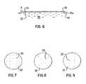
- FIG. 6is a cross sectional side view similar to FIG. 2 but showing a reduction in wafer edge exclusion.
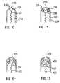
- FIGS. 7 , 8 and 9show various individual electrical contact distributions.
- FIG. 10shows another electrical contact.
- FIG. 11shows a further electrical contact.
- FIG. 12shows still another electrical contact.
- FIG. 13shows one more electrical contact.
- FIG. 14is a schematic illustration of a single electrical contact such as that shown in FIG. 13 while in contact with a wafer surface during application of an electric field.
- FIG. 15shows part of another electrical contact which is similar to those of FIGS. 12 and 13 but in which a roller and a roller support member have different sizes.
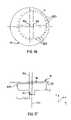
- FIG. 16is a view, from above a wafer or substrate which is to be plated, schematically showing electrical contacts surrounding a circular anode area which can be used according to the present invention.
- FIG. 17is a side view of the schematically illustrated assembly of FIG. 16 but in which only one of the electrical contacts is shown for reasons of clarity.
- FIG. 18shows an electrolyte seal location, right at a perimeter edge of a wafer, which permits full wafer face plating with zero edge exclusion.
- FIG. 19shows another electrolyte seal location, on a surface of a wafer facing away from an electrolyte, which permits full wafer face plating with zero edge exclusion.
- FIG. 20is a view similar to FIG. 16 but in which electrical contacts with alternative configurations are provided.
- FIG. 21is a top view of the porous pad overlying the anode plate, and of the electrical contacts, of FIG. 20 .
- FIG. 22is a view similar to FIG. 16 but showing one example of a non-circular anode area.
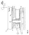
- FIG. 3A general depiction of one version of a plating apparatus is shown in FIG. 3 .
- the carrier head 10holds the wafer 16 .
- the waferhas the barrier layer and the seed layer (not shown in FIG. 3 ) deposited on its surface, and therefore its surface is conductive.
- the headcan be rotated around a first axis 10 b . It can also be moved in the x, y, and z directions.
- a pad 8is placed on an anode plate 9 across from the wafer surface.
- the pad surfacemay itself be abrasive, or the pad may contain an abrasive material.
- Pad designs and structuresform the subject matter of U.S. Ser. No. 09/511,278, filed Feb.
- Electrolyte 9 ais supplied to the wafer surface through openings in the anode plate and the pad as shown by the arrows in FIG. 3 .
- U.S. Ser. No. 09/568,584, filed May 11, 2000, entitled Anode Assembly For Plating And Planarizing A Conductive Layerdiscloses an anode plate
- U.S. Ser. No. 09/544,558, filed Apr. 6, 2000, entitled Modified Plating Solution For Plating And Planarizationdiscloses an electrolyte, both incorporated herein by reference.
- the electrolytethen flows over the edges of the pad into the chamber 9 c to be re-circulated after cleaning/filtering/refurbishing.
- An electrical contact 9 dis provided to the anode plate.
- the anode plateturns around the axis 10 c.
- the platemay also be translated in the x, y, and/or z directions.
- Axes 10 b and 10 care substantially parallel to each other.
- the diameter of the pad 8is typically smaller than the diameter of the wafer surface exposed to the pad surface, although it may also be larger.
- the gap between the wafer surface and the padis adjustable by moving the carrier head and/or the anode plate in the z direction.
- the workpiecei.e., the wafer or substrate
- the workpiecemay be brought close to the pad, without touching the pad.
- the workpiecehydroplanes or floats over the pad or anode.
- the wafer surface and the padmay be in contact. When the wafer surface and the pad are touching, the pressure that is exerted on the wafer and pad surfaces can also be adjusted.
- Electrical connection to the wafer surfacecan be made by way of multiple electrical contacts formed by pins that come up through the pad 8 and touch the wafer surface. Assuming by way of example that it is the structure shown in FIG. 1 that is to be plated, and referring now to FIG. 4 , it will be understood that the wafer surface 22 is formed by the exposed surface of the seed layer 4 . A magnified view of one of the multiple electrical contacts which can be used is shown in FIG. 4 . Holes 24 have been provided in the anode plate 9 to accommodate the pins 20 . These pins 20 are electrically isolated from the anode plate 9 by an insulator 26 . The insulator may be a ceramic or other appropriate dielectric material.
- a seal 25is interposed between the anode plate 9 and the insulator 26 .
- the pins 20 forming the electrical contactsare an integral part of a cathode plate 30 , which is also electrically isolated from the anode plate 9 by the insulator 26 .
- the cathode plate 30is spring loaded by suitable springs 32 which bias or push the rounded tips 20 T of the pins 20 towards the wafer surface 22 during the plating operation.
- the electrical contactscan slide up under the spring bias and down against the spring bias to adjust dynamically to the carrier head or workpiece location relative to the anode plate.
- a roller ballsimilar to that which could be used in a ball-point pen, can be incorporated at the tips 20 T to prevent scratching the wafer surface.
- Various additional or alternative electrical contact configurationswill be described in connection with FIGS. 10-15 .
- Soft conductive brushescould also be used to make contact to the wafer surface. It is important that the selected contacts do not scratch the wafer surface excessively.
- the electrolyte 9 ais supplied to the gap 34 between the pad 8 and the wafer surface 22 and thus is brought into physical contact with the wafer surface and the anode plate.
- the wafer 16is brought down until its surface 22 makes physical contact to the tips 20 T of the pins 20 .
- a potentialis applied between the cathode plate 30 and the anode plate 9 , making the cathode plate 30 more negative than the anode plate 9 . Therefore, the wafer surface is also rendered cathodic through the pins 20 . Under applied potential, copper plates out of the electrolyte 9 a onto the wafer surface 22 .
- the gap 34 between the pad 8 and the wafer surface 22 and/or by adjusting the pressure with which the pad 8 and the wafer surface 22 touch each otherone can achieve just plating, or plating and polishing.
- the pad 8have an abrasive surface or that the whole pad 8 is abrasive.
- the wafer or substrate 16 and the anode plate/pad assembly 8 , 9should rotate with respect to one another so that plating takes place uniformly. They may also translate in one or two directions.
- the electrolyte 9 atypically fills any gap 34 between the pad 8 and the wafer surface 22 .
- the electrolytecan be either applied through channels in the anode plate 9 and the pad 8 (not shown in FIG. 4 ) or, if the gap 34 is large (e.g. 2 mm or larger), provided into the gap 34 from the edges of the wafer.
- the pin tips 20 Tmay be disposed in close proximity to the wafer surface 22 without touching this surface for other applications.
- coppermay be either plated onto or removed from the wafer, depending on the polarity of the wafer. Circuitry used for application and adjustment of the applied potential, and for inverting the polarity of the potential, is well known and commonly used.
- a potential conductive pad 80In the construction shown in FIG. 5 , electrical contact to the wafer surface is made by way of a potential conductive pad 80 .
- This pad 80is used in place of the multiple pins 20 .
- an insulating spacer 82 of ceramic or other dielectric materialis placed directly over the anode plate 9 ′ between the anode plate 9 ′ and the conductive pad 80 .
- Electrical supply contactsare made to the conductive pad 80 and the anode plate 9 ′, and a cathodic potential is applied to the pad 80 , with electrolyte 9 a making physical contact to the anode plate 9 ′, the pad 80 and the wafer surface 22 .
- FIG. 5is similar to certain pad designs and structures forming the subject matter of application Ser. No. 09/511,278, filed Feb. 23, 2000, mentioned previously. Additionally, U.S. Ser. No. 09/483,095, filed Jan. 14, 2000, entitled Semiconductor Workpiece Proximity Plating Methods And Apparatus, discloses conductive pad strips used on cylindrical anodes. In other applications, the potential conductive pad 80 may be allowed to float with respect to the wafer surface 22 during material deposition or removal. The potential, moreover, may be pulsed to produce impulse plating. Again, the circuitry used for pulsing the potential is well known and commonly used.
- some Cu platingmay take place on the exposed cathodic surfaces besides the wafer surface.
- exposed regions of the pinsmay get coated.
- the whole padmay get coated. Therefore, it is of utmost importance to select the right conductive materials to be used for the construction of the electrical contacts and the pads.
- the materialsshould be such that plating on the Cu coated wafer surface (i.e. the seed layer 4 of FIG. 1 ) should be preferable or more efficient than plating on the pad or contact surface.
- Examples of proper materials for the padsmay be various conductive polymers or polymeric materials that are coated with refractory metals such as Ta, alpha Ta, W, Mo or their nitrides.
- the pins or other electrical contactscan be made of conductive polymers or refractory metals such as Mo, Ta and W; alternatively, the pins or other cathode contacts can be made of any conductive metal such as Cu or Ni, or of a conductive alloy such as Cu—Be, Cu—Ag, Ag—Pt, etc., but these metals or alloys may be coated by a refractory metal or compound and/or a nitride of a refractory metal, such as TaN or TiN, or of a refractory compound. These are just some examples. There are many more materials on which Cu does not deposit efficiently.
- the “edge exclusion” discussed earlier in connection with FIG. 2can be reduced on the wafer.
- eliminating the need for a contact ring to contact the periphery of the waferpermits a reduction of the edge exclusion “d”.
- the seal 18can be either on the surface 22 of the wafer 16 facing the electrolyte 9 a or right at the edge 16 a of the wafer. The seal 18 may even be disposed on the surface 35 of the wafer 16 facing away from the electrolyte 9 a.
- FIGS. 7-9schematically show three possible types of distribution of pins 20 over a cathode plate 30 .
- the voltage drop from the center to the edge of the waferwill become smaller, and the thickness of the plated metal becomes more uniform.
- any metal or conductive alloycan be plated on a wafer/substrate surface.
- an electroplating technique and an electroplating apparatushave been described, the same apparatus can be utilized for electroetching and/or electro-polishing. In these cases, the polarity of the voltage applied between the anode and cathode plates is reversed, making the substrate surface more positive.
- An electro-etching electrolytemay be used. Again, the circuitry used for application and adjustment of the voltage, and for inversion of the voltage polarity, is well known and commonly used.
- FIG. 10shows one of a plurality of electrical contacts which may be used as alternatives to, or together with, pins such as the pins 20 , or together with other electrical contact configurations, to provide electrical connection to a wafer surface.
- FIGS. 11-13 and 15also show additional electrical contact configurations which can be used as alternatives to, or together with, other contact configurations.
- Each electrical contact as shown in FIG. 10includes a conductive roller 120 , which is preferably spherical in geometry. Rollers having other suitable geometrical shapes, such as cylindrical rollers, may be used. The rollers are preferably coated with a corrosion resistant material such as gold, platinum, palladium, their alloys, or some other appropriate contact alloy material.
- the roller 120may be housed in an arrangement that may include, but is not limited to, a contact spring 122 to supply electrical power from the cathode plate (not shown) to the roller 120 .
- the end of the spring 122also acts as a bearing surface.
- the spring 122allows for a gentle but dynamic loading of the roller 120 on the surface of the workpiece.
- Each spring 122biases its respective roller toward the wafer surface.
- the electrical contact per seis formed by the roller 120 and the spring 122 which supports the roller.
- Each spring 122extends between the cathode plate (not shown in FIG. 10 ), on which the spring is supported in any appropriate fashion, and the roller 120 supported by the spring.
- Both the spring 122 and the roller 120are surrounded by an insulator 124 of a ceramic or other appropriate dielectric material that isolates the spring 122 and the roller 120 from an electric field during the process of plating Cu out of the electrolyte.
- the insulator 124may be configured similarly to the insulator 26 , represented in FIG. 4 , but can include a shaped tip 128 .
- the shaped tip 128 and a seal 126are disposed around the roller 120 .
- the seal 126may be adhesively or otherwise secured to the inner surface of the shaped tip.
- the seal arrangementis such that the roller 120 rotates freely with respect to the seal 126 .
- the electrolyte fluid boundary layerand, if the electrolyte forming the subject matter of copending application Ser. No. 09/544,558 mentioned above is used, especially the additive in the electrolyte, helps lubricate the roller surface.
- the tip 128In addition to housing the roller 120 and the seal 126 , the tip 128 also prevents the roller 120 from exposure to the electric field.
- FIG. 14which shows one electrical contact with a different configuration in use, indicates an applied electric field by reference characters E. The tip and seal configuration helps prevent or minimize material deposition on the roller 120 .
- FIG. 11shows another configuration in which a rolling pad 230 of conducting material (e.g. metal), preferably with a partially spherical shaped surface, is disposed between the contact spring 222 and a spherical roller 220 .
- the roller 220rests on the shaped rolling pad 230 .
- the shaped tip 228 and the seal 226cooperate with the spring biased rolling pad 230 to confine the roller 220 while allowing it to rotate freely along any direction.
- the roller 220protrudes partly through but is restrained by the perimeter of an end opening in the insulator 224 which surrounds the seal 226 , the spring 222 , and the rolling pad 230 .
- the electrical contact per seis formed by the roller 220 , the spring 222 , and the spring biased rolling pad 230 disposed between the roller and the spring.
- FIG. 12shows that a conductive roller 320 may rest on a support member 330 having, for example, a spherical supporting surface rather than on a rolling pad. Multiple support members could be used beneath the roller 320 . Such an arrangement is ideal for self-aligned roller contact.
- the electrical contact per seis formed by the roller 320 , the spring 322 , and the support member 330 .
- the rolling friction between the roller 320 and the substrate or workpieceis greatly reduced, especially when the workpiece rotates or translates during the process of plating Cu out of the electrolyte.
- the reduced frictionminimizes undesirable workpiece scratching and damage as well as particulate generation.
- FIG. 13shows a spherical support 430 in use during conductive material deposition. Also, as shown in FIG. 15 , the size of the roller 520 may be different from that of the roller support member 530 .
- the roller material, the contact spring material, and the likemust be such that they do not degrade or dissolve in the electrolyte of interest. It is also desirable that these materials do not degrade the quality of the material deposited.
- the rollerfor example, can not excessively scratch the deposited film or generate very undesirable particulates.
- Numerous face contactsmay be made around the periphery of the wafer. The individual contacts may be discrete and range from 4 to about 2000 in number, depending on size of the substrate. As the size of the wafer or substrate increases, the number of electrical contacts used should also increase.
- the roller contactscould also be a continuous race track or a track which is split into several elements. For example, the periphery may be divided into quadrants or octets. Each quadrant, etc., may contain many more or less uniformly dispersed roller contacts or contact tips.
- FIGS. 16 and 17One preferred apparatus which can be used to make electrical contact according to this invention is shown in FIGS. 16 and 17 .
- Electrical contact to the electrolyte 9 ais made via an electrode (or anode) in the form of a round anode plate 9 which, as illustrated, has a diameter smaller than the diameter of the wafer or substrate 16 .
- the anode plate 9 of FIGS. 16 and 17can have essentially the same construction as that of the anode plate 9 of FIG. 3 . Holes in the anode plate 9 of FIGS. 16 and 17 for electrical contact pin accommodation, however, are not needed for reasons which will be come clear.
- a work piece carrier head(not shown in FIGS.
- the carrier head, the anode plate 9 , or both,can also be translated in the x, y, and/or z directions.
- An electrical contact 9 dis provided to the anode plate.
- Electrical contact to the wafer frontal side 22rendering the wafer barrier layer and/or the wafer seed layer cathodic, is made outside the anode area via a set of electrical contacts 603 .
- the anode areais shown in phantom in FIG. 16 and, as illustrated, is circular.
- the electrical contactssurround and are preferably situated concentric with the anode plate 9 as shown in FIG. 16 .
- the wafer 16is allowed to rotate and move with respect to the anode plate 9 and the wafer contacts 603 . In this way, there is no restriction on electrochemical plating all the way to the edge of the wafer 16 or, more particularly, the edge of the seed layer on the wafer.
- the anode plate 9may also be allowed to rotate with respect to the contacts 603 , but this is not a necessary condition.
- the electrical wafer contacts 603could be conductive wires or pins pushed against the wafer, but could also be spherical balls pushed or spring-loaded against the wafer.
- the electrical wafer contacts 603 per se of FIGS. 16-18can have the same structure as any of the electrical contacts previously described in connection with FIGS. 4 , 10 - 13 , and 15 , and can be constructed of the same materials. Combinations of various previously described electrical contact surfaces are also contemplated.
- the contacts 603are mounted on or interconnected with a cathodic element such as a contact ring, similar to that which will be described in connection with FIGS. 20 and 21 , rather than with a cathode plate as described in connection with FIG. 4 .
- the wafer 16in each embodiment of FIGS. 16-22 , can be vacuum mounted, without clamping, to the workpiece carrier head (not shown).
- the workpiece carrier head(not shown).
- One way by which vacuum mounting can be achievedis described in application Ser. No. 09/472,523 mentioned earlier.
- Other ways of vacuum mounting the wafer to a workpiece carrier headcould readily be made and used by those of ordinary skill in the art.
- FIGS. 18 and 19show how the present invention permits full-face plating with zero edge exclusion.
- a seal 18can be located right at the perimeter edge of the wafer 16 ( FIG. 8 ) or may even be disposed on the surface 35 of the wafer 16 facing away from the electrolyte ( FIG. 19 ) in a manner similar to that previously described in connection with FIG. 6 .
- the contacts 603therefore, can sweep the whole wafer frontal side surface 22 , and can also slide off of this surface, so as to allow conductive material plating over the whole surface 22 .
- FIGS. 20 and 21show a preferred electrical wafer contact structure which differs from that of FIGS. 16 and 17 .
- the anode plate 9 illustrated in FIG. 20is constructed the same as the anode plate 9 of FIGS. 16 and 17 .
- a workpiece carrier head(not shown), which holds the wafer 16 , can be rotated around a first axis, while the anode plate 9 can turn around a second axis.
- the carrier head, the anode plate 9 , or bothcan also be translated in the x, y, and/or z directions.
- An electrical contact 9 dis provided to the anode plate.
- FIG. 20also schematically illustrates the flow of the electrolyte 9 a through both the anode plate 9 and a porous pad 8 , which is also shown in FIGS. 20 and 21 .
- the pad 8can have an appropriately adapted design similar to any of those disclosed by either U.S. patent application Ser. No. 09/511,278 or U.S. patent application Ser. No. 09/621,969 mentioned previously, and permits through-flow of the electrolyte 9 a .
- the pad 8is shown in phantom in FIG. 20 , since the pad may or may not be provided, depending on the particular operation which is to be performed. No pad is necessary for plating or etching. For plating and polishing, however, a pad 8 is necessary.
- a contact ring 610formed of a conductive metal, a conductive metal alloy, or some other appropriately conductive material, surrounds but is spaced from the perimeter of the anode plate 9 .
- the contact ring 610could, for example, be connected with a housing within which the anode plate 9 is movable back and forth in the z direction.
- Electrical contactsin the form of conductive brushes or any of the previously mentioned conductive pins, wires, balls, rollers, etc., or combinations thereof (conductive brushes 613 are shown in FIGS. 20 and 21 ), are disposed on or mounted to the contact ring 610 and can be pushed or spring loaded against the wafer frontal side.
- the wafer 16is moved with respect to the anode plate 9 .
- the contacts, such as brushes 613may make physical contact to the surface of the wafer and may be partially or fully displaced off, or outside, of the wafer surface for certain periods of time during plating. This permits control of the conductive material deposit uniformity.
- FIG. 22which is a view similar to FIG. 16 , shows that it is possible to have other, differently shaped contact rings and/or anode plate assemblies with non-circular anode areas.
- FIG. 22illustrates, by way of example only, a rectangular anode plate 9 ′, a set of electrical contacts 603 ′ arranged in a rectangular configuration around the anode plate 9 ′, and a wafer 16 .
- the anode plate 9 ′, the wafer 16 , or bothare movable with respect to one another in the directions indicated by arrows to effect proper plating, etching, or plating and polishing operations.
- the contactscan be, for example, pins with rounded tips, rollers, in the form of brushes, or various combinations of these configurations.
Landscapes
- Chemical & Material Sciences (AREA)
- Engineering & Computer Science (AREA)
- Chemical Kinetics & Catalysis (AREA)
- Electrochemistry (AREA)
- Materials Engineering (AREA)
- Metallurgy (AREA)
- Organic Chemistry (AREA)
- Life Sciences & Earth Sciences (AREA)
- Sustainable Development (AREA)
- Electroplating Methods And Accessories (AREA)
- Electrodes Of Semiconductors (AREA)
Abstract
Description
Claims (20)
Priority Applications (1)
| Application Number | Priority Date | Filing Date | Title |
|---|---|---|---|
| US10/947,628US7476304B2 (en) | 2000-03-17 | 2004-09-21 | Apparatus for processing surface of workpiece with small electrodes and surface contacts |
Applications Claiming Priority (6)
| Application Number | Priority Date | Filing Date | Title |
|---|---|---|---|
| US19002300P | 2000-03-17 | 2000-03-17 | |
| US20394400P | 2000-05-12 | 2000-05-12 | |
| US09/685,934US6497800B1 (en) | 2000-03-17 | 2000-10-11 | Device providing electrical contact to the surface of a semiconductor workpiece during metal plating |
| US09/735,546US6482307B2 (en) | 2000-05-12 | 2000-12-14 | Method of and apparatus for making electrical contact to wafer surface for full-face electroplating or electropolishing |
| US10/265,460US6852208B2 (en) | 2000-03-17 | 2002-10-03 | Method and apparatus for full surface electrotreating of a wafer |
| US10/947,628US7476304B2 (en) | 2000-03-17 | 2004-09-21 | Apparatus for processing surface of workpiece with small electrodes and surface contacts |
Related Parent Applications (1)
| Application Number | Title | Priority Date | Filing Date |
|---|---|---|---|
| US10/265,460ContinuationUS6852208B2 (en) | 2000-03-17 | 2002-10-03 | Method and apparatus for full surface electrotreating of a wafer |
Publications (2)
| Publication Number | Publication Date |
|---|---|
| US20050034994A1 US20050034994A1 (en) | 2005-02-17 |
| US7476304B2true US7476304B2 (en) | 2009-01-13 |
Family
ID=34139897
Family Applications (2)
| Application Number | Title | Priority Date | Filing Date |
|---|---|---|---|
| US10/265,460Expired - Fee RelatedUS6852208B2 (en) | 2000-03-17 | 2002-10-03 | Method and apparatus for full surface electrotreating of a wafer |
| US10/947,628Expired - Fee RelatedUS7476304B2 (en) | 2000-03-17 | 2004-09-21 | Apparatus for processing surface of workpiece with small electrodes and surface contacts |
Family Applications Before (1)
| Application Number | Title | Priority Date | Filing Date |
|---|---|---|---|
| US10/265,460Expired - Fee RelatedUS6852208B2 (en) | 2000-03-17 | 2002-10-03 | Method and apparatus for full surface electrotreating of a wafer |
Country Status (1)
| Country | Link |
|---|---|
| US (2) | US6852208B2 (en) |
Cited By (1)
| Publication number | Priority date | Publication date | Assignee | Title |
|---|---|---|---|---|
| US8268154B1 (en) | 2002-07-29 | 2012-09-18 | Novellus Systems, Inc. | Selective electrochemical accelerator removal |
Families Citing this family (15)
| Publication number | Priority date | Publication date | Assignee | Title |
|---|---|---|---|---|
| US6991528B2 (en)* | 2000-02-17 | 2006-01-31 | Applied Materials, Inc. | Conductive polishing article for electrochemical mechanical polishing |
| US6962524B2 (en)* | 2000-02-17 | 2005-11-08 | Applied Materials, Inc. | Conductive polishing article for electrochemical mechanical polishing |
| US6896776B2 (en)* | 2000-12-18 | 2005-05-24 | Applied Materials Inc. | Method and apparatus for electro-chemical processing |
| US7211174B2 (en)* | 2001-01-17 | 2007-05-01 | Novellus Systems, Inc. | Method and system to provide electrical contacts for electrotreating processes |
| US6863794B2 (en)* | 2001-09-21 | 2005-03-08 | Applied Materials, Inc. | Method and apparatus for forming metal layers |
| DE10239163A1 (en)* | 2002-08-23 | 2004-03-04 | Fraunhofer-Gesellschaft zur Förderung der angewandten Forschung e.V. | Device and method for forming gradient layers on substrates in a vacuum chamber |
| US7704367B2 (en)* | 2004-06-28 | 2010-04-27 | Lam Research Corporation | Method and apparatus for plating semiconductor wafers |
| US20050173260A1 (en)* | 2003-03-18 | 2005-08-11 | Basol Bulent M. | System for electrochemical mechanical polishing |
| US7041600B2 (en)* | 2003-06-30 | 2006-05-09 | International Business Machines Corporation | Methods of planarization |
| US7648622B2 (en)* | 2004-02-27 | 2010-01-19 | Novellus Systems, Inc. | System and method for electrochemical mechanical polishing |
| US7498062B2 (en)* | 2004-05-26 | 2009-03-03 | Wd Media, Inc. | Method and apparatus for applying a voltage to a substrate during plating |
| US20070034526A1 (en)* | 2005-08-12 | 2007-02-15 | Natsuki Makino | Electrolytic processing apparatus and method |
| DE102009021561A1 (en)* | 2009-05-15 | 2010-11-18 | Rolls-Royce Deutschland Ltd & Co Kg | Method and apparatus for surface etching of integrally bladed rotors |
| CN104152979B (en)* | 2014-09-04 | 2017-02-01 | 蒙家革 | Electrolytic etching head, numerical-control electrolytic etching system and etching method |
| EP3835461A1 (en)* | 2019-12-13 | 2021-06-16 | CSEM Centre Suisse D'electronique Et De Microtechnique SA | Substrate carrier for metallic electroplating of substrates |
Citations (84)
| Publication number | Priority date | Publication date | Assignee | Title |
|---|---|---|---|---|
| US2540602A (en) | 1946-07-03 | 1951-02-06 | Lockheed Aircraft Corp | Method and apparatus for the surface treatment of metals |
| US2708181A (en) | 1951-05-17 | 1955-05-10 | Indiana Steel & Wire Company I | Electroplating process |
| US3328273A (en) | 1966-08-15 | 1967-06-27 | Udylite Corp | Electro-deposition of copper from acidic baths |
| US4430173A (en) | 1981-07-24 | 1984-02-07 | Rhone-Poulenc Specialties Chimiques | Additive composition, bath and process for acid copper electroplating |
| US4713149A (en) | 1985-11-26 | 1987-12-15 | Shigeo Hoshino | Method and apparatus for electroplating objects |
| US4948474A (en) | 1987-09-18 | 1990-08-14 | Pennsylvania Research Corporation | Copper electroplating solutions and methods |
| US4954142A (en) | 1989-03-07 | 1990-09-04 | International Business Machines Corporation | Method of chemical-mechanical polishing an electronic component substrate and polishing slurry therefor |
| US4975159A (en) | 1988-10-24 | 1990-12-04 | Schering Aktiengesellschaft | Aqueous acidic bath for electrochemical deposition of a shiny and tear-free copper coating and method of using same |
| US5084071A (en) | 1989-03-07 | 1992-01-28 | International Business Machines Corporation | Method of chemical-mechanical polishing an electronic component substrate and polishing slurry therefor |
| US5256565A (en) | 1989-05-08 | 1993-10-26 | The United States Of America As Represented By The United States Department Of Energy | Electrochemical planarization |
| US5292399A (en) | 1990-04-19 | 1994-03-08 | Applied Materials, Inc. | Plasma etching apparatus with conductive means for inhibiting arcing |
| US5354490A (en) | 1992-06-04 | 1994-10-11 | Micron Technology, Inc. | Slurries for chemical mechanically polishing copper containing metal layers |
| US5466161A (en) | 1993-10-01 | 1995-11-14 | Bourns, Inc. | Compliant stacking connector for printed circuit boards |
| US5472592A (en) | 1994-07-19 | 1995-12-05 | American Plating Systems | Electrolytic plating apparatus and method |
| US5516412A (en) | 1995-05-16 | 1996-05-14 | International Business Machines Corporation | Vertical paddle plating cell |
| US5567300A (en) | 1994-09-02 | 1996-10-22 | Ibm Corporation | Electrochemical metal removal technique for planarization of surfaces |
| US5605637A (en) | 1994-12-15 | 1997-02-25 | Applied Materials Inc. | Adjustable dc bias control in a plasma reactor |
| US5681215A (en) | 1995-10-27 | 1997-10-28 | Applied Materials, Inc. | Carrier head design for a chemical mechanical polishing apparatus |
| US5755859A (en) | 1995-08-24 | 1998-05-26 | International Business Machines Corporation | Cobalt-tin alloys and their applications for devices, chip interconnections and packaging |
| US5762544A (en) | 1995-10-27 | 1998-06-09 | Applied Materials, Inc. | Carrier head design for a chemical mechanical polishing apparatus |
| US5770095A (en) | 1994-07-12 | 1998-06-23 | Kabushiki Kaisha Toshiba | Polishing agent and polishing method using the same |
| WO1998027585A1 (en) | 1996-12-16 | 1998-06-25 | International Business Machines Corporation | Electroplated interconnection structures on integrated circuit chips |
| US5772833A (en) | 1993-11-20 | 1998-06-30 | Tokyo Electron Limited | Plasma etching apparatus |
| US5773364A (en) | 1996-10-21 | 1998-06-30 | Motorola, Inc. | Method for using ammonium salt slurries for chemical mechanical polishing (CMP) |
| US5793272A (en) | 1996-08-23 | 1998-08-11 | International Business Machines Corporation | Integrated circuit toroidal inductor |
| US5795215A (en) | 1995-06-09 | 1998-08-18 | Applied Materials, Inc. | Method and apparatus for using a retaining ring to control the edge effect |
| US5807165A (en) | 1997-03-26 | 1998-09-15 | International Business Machines Corporation | Method of electrochemical mechanical planarization |
| US5840629A (en) | 1995-12-14 | 1998-11-24 | Sematech, Inc. | Copper chemical mechanical polishing slurry utilizing a chromate oxidant |
| US5858813A (en) | 1996-05-10 | 1999-01-12 | Cabot Corporation | Chemical mechanical polishing slurry for metal layers and films |
| US5862605A (en) | 1996-05-24 | 1999-01-26 | Ebara Corporation | Vaporizer apparatus |
| US5897375A (en) | 1997-10-20 | 1999-04-27 | Motorola, Inc. | Chemical mechanical polishing (CMP) slurry for copper and method of use in integrated circuit manufacture |
| US5911619A (en) | 1997-03-26 | 1999-06-15 | International Business Machines Corporation | Apparatus for electrochemical mechanical planarization |
| US5922091A (en) | 1997-05-16 | 1999-07-13 | National Science Council Of Republic Of China | Chemical mechanical polishing slurry for metallic thin film |
| US5930669A (en) | 1997-04-03 | 1999-07-27 | International Business Machines Corporation | Continuous highly conductive metal wiring structures and method for fabricating the same |
| US5933753A (en) | 1996-12-16 | 1999-08-03 | International Business Machines Corporation | Open-bottomed via liner structure and method for fabricating same |
| US5954997A (en) | 1996-12-09 | 1999-09-21 | Cabot Corporation | Chemical mechanical polishing slurry useful for copper substrates |
| JPH11279797A (en) | 1998-03-27 | 1999-10-12 | Dainippon Screen Mfg Co Ltd | Substrate plating apparatus |
| US5985123A (en) | 1997-07-09 | 1999-11-16 | Koon; Kam Kwan | Continuous vertical plating system and method of plating |
| US6004880A (en) | 1998-02-20 | 1999-12-21 | Lsi Logic Corporation | Method of single step damascene process for deposition and global planarization |
| US6027631A (en) | 1997-11-13 | 2000-02-22 | Novellus Systems, Inc. | Electroplating system with shields for varying thickness profile of deposited layer |
| WO2000026443A2 (en) | 1998-11-03 | 2000-05-11 | Nutool, Inc. | Method and apparatus for electrochemical mechanical deposition |
| US6063506A (en) | 1995-06-27 | 2000-05-16 | International Business Machines Corporation | Copper alloys for chip and package interconnections |
| US6066030A (en) | 1999-03-04 | 2000-05-23 | International Business Machines Corporation | Electroetch and chemical mechanical polishing equipment |
| US6071388A (en) | 1998-05-29 | 2000-06-06 | International Business Machines Corporation | Electroplating workpiece fixture having liquid gap spacer |
| US6074544A (en) | 1998-07-22 | 2000-06-13 | Novellus Systems, Inc. | Method of electroplating semiconductor wafer using variable currents and mass transfer to obtain uniform plated layer |
| US6103085A (en) | 1998-12-04 | 2000-08-15 | Advanced Micro Devices, Inc. | Electroplating uniformity by diffuser design |
| US6106660A (en) | 1998-02-20 | 2000-08-22 | United Semiconductor Corp. | Etching machine having lower electrode bias voltage source |
| US6106680A (en) | 1999-01-26 | 2000-08-22 | Amd | Apparatus for forming a copper interconnect |
| US6132586A (en) | 1998-06-11 | 2000-10-17 | Integrated Process Equipment Corporation | Method and apparatus for non-contact metal plating of semiconductor wafers using a bipolar electrode assembly |
| US6132587A (en) | 1998-10-19 | 2000-10-17 | Jorne; Jacob | Uniform electroplating of wafers |
| US6136163A (en) | 1999-03-05 | 2000-10-24 | Applied Materials, Inc. | Apparatus for electro-chemical deposition with thermal anneal chamber |
| US6143155A (en) | 1998-06-11 | 2000-11-07 | Speedfam Ipec Corp. | Method for simultaneous non-contact electrochemical plating and planarizing of semiconductor wafers using a bipiolar electrode assembly |
| US6153064A (en) | 1998-11-25 | 2000-11-28 | Oliver Sales Company | Apparatus for in line plating |
| US6156167A (en) | 1997-11-13 | 2000-12-05 | Novellus Systems, Inc. | Clamshell apparatus for electrochemically treating semiconductor wafers |
| US6159354A (en) | 1997-11-13 | 2000-12-12 | Novellus Systems, Inc. | Electric potential shaping method for electroplating |
| US6187152B1 (en) | 1998-07-17 | 2001-02-13 | Cutek Research, Inc. | Multiple station processing chamber and method for depositing and/or removing material on a substrate |
| US6217734B1 (en)* | 1999-02-23 | 2001-04-17 | International Business Machines Corporation | Electroplating electrical contacts |
| US6217134B1 (en) | 1998-09-30 | 2001-04-17 | Aisin Seiki Kabushiki Kaisha | Anti-skid control system for an automotive vehicle |
| US6251235B1 (en) | 1999-03-30 | 2001-06-26 | Nutool, Inc. | Apparatus for forming an electrical contact with a semiconductor substrate |
| US6251236B1 (en) | 1998-11-30 | 2001-06-26 | Applied Materials, Inc. | Cathode contact ring for electrochemical deposition |
| US6270646B1 (en) | 1999-12-28 | 2001-08-07 | International Business Machines Corporation | Electroplating apparatus and method using a compressible contact |
| US6299741B1 (en) | 1999-11-29 | 2001-10-09 | Applied Materials, Inc. | Advanced electrolytic polish (AEP) assisted metal wafer planarization method and apparatus |
| US6334937B1 (en) | 1998-12-31 | 2002-01-01 | Semitool, Inc. | Apparatus for high deposition rate solder electroplating on a microelectronic workpiece |
| US6379223B1 (en) | 1999-11-29 | 2002-04-30 | Applied Materials, Inc. | Method and apparatus for electrochemical-mechanical planarization |
| US20020074238A1 (en) | 1998-10-26 | 2002-06-20 | Mayer Steven T. | Method and apparatus for uniform electropolishing of damascene ic structures by selective agitation |
| US20020102853A1 (en) | 2000-12-22 | 2002-08-01 | Applied Materials, Inc. | Articles for polishing semiconductor substrates |
| US6440295B1 (en) | 1998-07-09 | 2002-08-27 | Acm Research, Inc. | Method for electropolishing metal on semiconductor devices |
| US6454926B1 (en)* | 1997-09-30 | 2002-09-24 | Semitool Inc. | Semiconductor plating system workpiece support having workpiece-engaging electrode with submerged conductive current transfer areas |
| US6482307B2 (en) | 2000-05-12 | 2002-11-19 | Nutool, Inc. | Method of and apparatus for making electrical contact to wafer surface for full-face electroplating or electropolishing |
| US6497800B1 (en) | 2000-03-17 | 2002-12-24 | Nutool Inc. | Device providing electrical contact to the surface of a semiconductor workpiece during metal plating |
| US6506103B1 (en) | 1999-07-23 | 2003-01-14 | Riken | ELID centerless grinding apparatus |
| US6527925B1 (en) | 1998-07-10 | 2003-03-04 | Semitool, Inc. | Contact assemblies, methods for making contact assemblies, and plating machines with contact assemblies for plating microelectronic workpieces |
| US6534116B2 (en) | 2000-08-10 | 2003-03-18 | Nutool, Inc. | Plating method and apparatus that creates a differential between additive disposed on a top surface and a cavity surface of a workpiece using an external influence |
| US20030054729A1 (en) | 2000-08-30 | 2003-03-20 | Whonchee Lee | Methods and apparatus for electromechanically and/or electrochemically-mechanically removing conductive material from a microelectronic substrate |
| US6537144B1 (en) | 2000-02-17 | 2003-03-25 | Applied Materials, Inc. | Method and apparatus for enhanced CMP using metals having reductive properties |
| US6600229B2 (en) | 2001-01-23 | 2003-07-29 | Honeywell International Inc. | Planarizers for spin etch planarization of electronic components |
| US6610190B2 (en) | 2000-11-03 | 2003-08-26 | Nutool, Inc. | Method and apparatus for electrodeposition of uniform film with minimal edge exclusion on substrate |
| US6630059B1 (en) | 2000-01-14 | 2003-10-07 | Nutool, Inc. | Workpeice proximity plating apparatus |
| US6653226B1 (en) | 2001-01-09 | 2003-11-25 | Novellus Systems, Inc. | Method for electrochemical planarization of metal surfaces |
| US20030226764A1 (en) | 2000-08-30 | 2003-12-11 | Moore Scott E. | Methods and apparatus for electrochemical-mechanical processing of microelectronic workpieces |
| US20040178060A1 (en) | 2002-09-30 | 2004-09-16 | Lam Research Corp. | Apparatus and method for depositing and planarizing thin films of semiconductor wafers |
| US6848970B2 (en) | 2002-09-16 | 2005-02-01 | Applied Materials, Inc. | Process control in electrochemically assisted planarization |
| US6855239B1 (en) | 2002-09-27 | 2005-02-15 | Rahul Jairath | Plating method and apparatus using contactless electrode |
| US6902659B2 (en) | 1998-12-01 | 2005-06-07 | Asm Nutool, Inc. | Method and apparatus for electro-chemical mechanical deposition |
- 2002
- 2002-10-03USUS10/265,460patent/US6852208B2/ennot_activeExpired - Fee Related
- 2004
- 2004-09-21USUS10/947,628patent/US7476304B2/ennot_activeExpired - Fee Related
Patent Citations (92)
| Publication number | Priority date | Publication date | Assignee | Title |
|---|---|---|---|---|
| US2540602A (en) | 1946-07-03 | 1951-02-06 | Lockheed Aircraft Corp | Method and apparatus for the surface treatment of metals |
| US2708181A (en) | 1951-05-17 | 1955-05-10 | Indiana Steel & Wire Company I | Electroplating process |
| US3328273A (en) | 1966-08-15 | 1967-06-27 | Udylite Corp | Electro-deposition of copper from acidic baths |
| US4430173A (en) | 1981-07-24 | 1984-02-07 | Rhone-Poulenc Specialties Chimiques | Additive composition, bath and process for acid copper electroplating |
| US4713149A (en) | 1985-11-26 | 1987-12-15 | Shigeo Hoshino | Method and apparatus for electroplating objects |
| US4948474A (en) | 1987-09-18 | 1990-08-14 | Pennsylvania Research Corporation | Copper electroplating solutions and methods |
| US4975159A (en) | 1988-10-24 | 1990-12-04 | Schering Aktiengesellschaft | Aqueous acidic bath for electrochemical deposition of a shiny and tear-free copper coating and method of using same |
| US4954142A (en) | 1989-03-07 | 1990-09-04 | International Business Machines Corporation | Method of chemical-mechanical polishing an electronic component substrate and polishing slurry therefor |
| US5084071A (en) | 1989-03-07 | 1992-01-28 | International Business Machines Corporation | Method of chemical-mechanical polishing an electronic component substrate and polishing slurry therefor |
| US5256565A (en) | 1989-05-08 | 1993-10-26 | The United States Of America As Represented By The United States Department Of Energy | Electrochemical planarization |
| US5292399A (en) | 1990-04-19 | 1994-03-08 | Applied Materials, Inc. | Plasma etching apparatus with conductive means for inhibiting arcing |
| US5354490A (en) | 1992-06-04 | 1994-10-11 | Micron Technology, Inc. | Slurries for chemical mechanically polishing copper containing metal layers |
| US5466161A (en) | 1993-10-01 | 1995-11-14 | Bourns, Inc. | Compliant stacking connector for printed circuit boards |
| US5772833A (en) | 1993-11-20 | 1998-06-30 | Tokyo Electron Limited | Plasma etching apparatus |
| US5770095A (en) | 1994-07-12 | 1998-06-23 | Kabushiki Kaisha Toshiba | Polishing agent and polishing method using the same |
| US5472592A (en) | 1994-07-19 | 1995-12-05 | American Plating Systems | Electrolytic plating apparatus and method |
| US5567300A (en) | 1994-09-02 | 1996-10-22 | Ibm Corporation | Electrochemical metal removal technique for planarization of surfaces |
| US5605637A (en) | 1994-12-15 | 1997-02-25 | Applied Materials Inc. | Adjustable dc bias control in a plasma reactor |
| US5516412A (en) | 1995-05-16 | 1996-05-14 | International Business Machines Corporation | Vertical paddle plating cell |
| US5795215A (en) | 1995-06-09 | 1998-08-18 | Applied Materials, Inc. | Method and apparatus for using a retaining ring to control the edge effect |
| US6063506A (en) | 1995-06-27 | 2000-05-16 | International Business Machines Corporation | Copper alloys for chip and package interconnections |
| US5755859A (en) | 1995-08-24 | 1998-05-26 | International Business Machines Corporation | Cobalt-tin alloys and their applications for devices, chip interconnections and packaging |
| US5681215A (en) | 1995-10-27 | 1997-10-28 | Applied Materials, Inc. | Carrier head design for a chemical mechanical polishing apparatus |
| US5762544A (en) | 1995-10-27 | 1998-06-09 | Applied Materials, Inc. | Carrier head design for a chemical mechanical polishing apparatus |
| US5840629A (en) | 1995-12-14 | 1998-11-24 | Sematech, Inc. | Copper chemical mechanical polishing slurry utilizing a chromate oxidant |
| US5858813A (en) | 1996-05-10 | 1999-01-12 | Cabot Corporation | Chemical mechanical polishing slurry for metal layers and films |
| US5862605A (en) | 1996-05-24 | 1999-01-26 | Ebara Corporation | Vaporizer apparatus |
| US5793272A (en) | 1996-08-23 | 1998-08-11 | International Business Machines Corporation | Integrated circuit toroidal inductor |
| US5884990A (en) | 1996-08-23 | 1999-03-23 | International Business Machines Corporation | Integrated circuit inductor |
| US5773364A (en) | 1996-10-21 | 1998-06-30 | Motorola, Inc. | Method for using ammonium salt slurries for chemical mechanical polishing (CMP) |
| US5954997A (en) | 1996-12-09 | 1999-09-21 | Cabot Corporation | Chemical mechanical polishing slurry useful for copper substrates |
| WO1998027585A1 (en) | 1996-12-16 | 1998-06-25 | International Business Machines Corporation | Electroplated interconnection structures on integrated circuit chips |
| US5933753A (en) | 1996-12-16 | 1999-08-03 | International Business Machines Corporation | Open-bottomed via liner structure and method for fabricating same |
| US5807165A (en) | 1997-03-26 | 1998-09-15 | International Business Machines Corporation | Method of electrochemical mechanical planarization |
| US5911619A (en) | 1997-03-26 | 1999-06-15 | International Business Machines Corporation | Apparatus for electrochemical mechanical planarization |
| US5930669A (en) | 1997-04-03 | 1999-07-27 | International Business Machines Corporation | Continuous highly conductive metal wiring structures and method for fabricating the same |
| US5922091A (en) | 1997-05-16 | 1999-07-13 | National Science Council Of Republic Of China | Chemical mechanical polishing slurry for metallic thin film |
| US5985123A (en) | 1997-07-09 | 1999-11-16 | Koon; Kam Kwan | Continuous vertical plating system and method of plating |
| US6454926B1 (en)* | 1997-09-30 | 2002-09-24 | Semitool Inc. | Semiconductor plating system workpiece support having workpiece-engaging electrode with submerged conductive current transfer areas |
| US5897375A (en) | 1997-10-20 | 1999-04-27 | Motorola, Inc. | Chemical mechanical polishing (CMP) slurry for copper and method of use in integrated circuit manufacture |
| US6027631A (en) | 1997-11-13 | 2000-02-22 | Novellus Systems, Inc. | Electroplating system with shields for varying thickness profile of deposited layer |
| US6159354A (en) | 1997-11-13 | 2000-12-12 | Novellus Systems, Inc. | Electric potential shaping method for electroplating |
| US6156167A (en) | 1997-11-13 | 2000-12-05 | Novellus Systems, Inc. | Clamshell apparatus for electrochemically treating semiconductor wafers |
| US6004880A (en) | 1998-02-20 | 1999-12-21 | Lsi Logic Corporation | Method of single step damascene process for deposition and global planarization |
| US6106660A (en) | 1998-02-20 | 2000-08-22 | United Semiconductor Corp. | Etching machine having lower electrode bias voltage source |
| JPH11279797A (en) | 1998-03-27 | 1999-10-12 | Dainippon Screen Mfg Co Ltd | Substrate plating apparatus |
| US6071388A (en) | 1998-05-29 | 2000-06-06 | International Business Machines Corporation | Electroplating workpiece fixture having liquid gap spacer |
| US6143155A (en) | 1998-06-11 | 2000-11-07 | Speedfam Ipec Corp. | Method for simultaneous non-contact electrochemical plating and planarizing of semiconductor wafers using a bipiolar electrode assembly |
| US6132586A (en) | 1998-06-11 | 2000-10-17 | Integrated Process Equipment Corporation | Method and apparatus for non-contact metal plating of semiconductor wafers using a bipolar electrode assembly |
| US6440295B1 (en) | 1998-07-09 | 2002-08-27 | Acm Research, Inc. | Method for electropolishing metal on semiconductor devices |
| US6527925B1 (en) | 1998-07-10 | 2003-03-04 | Semitool, Inc. | Contact assemblies, methods for making contact assemblies, and plating machines with contact assemblies for plating microelectronic workpieces |
| US6187152B1 (en) | 1998-07-17 | 2001-02-13 | Cutek Research, Inc. | Multiple station processing chamber and method for depositing and/or removing material on a substrate |
| US6074544A (en) | 1998-07-22 | 2000-06-13 | Novellus Systems, Inc. | Method of electroplating semiconductor wafer using variable currents and mass transfer to obtain uniform plated layer |
| US6162344A (en) | 1998-07-22 | 2000-12-19 | Novellus Systems, Inc. | Method of electroplating semiconductor wafer using variable currents and mass transfer to obtain uniform plated layer |
| US6217134B1 (en) | 1998-09-30 | 2001-04-17 | Aisin Seiki Kabushiki Kaisha | Anti-skid control system for an automotive vehicle |
| US6132587A (en) | 1998-10-19 | 2000-10-17 | Jorne; Jacob | Uniform electroplating of wafers |
| US20020074238A1 (en) | 1998-10-26 | 2002-06-20 | Mayer Steven T. | Method and apparatus for uniform electropolishing of damascene ic structures by selective agitation |
| US6402925B2 (en) | 1998-11-03 | 2002-06-11 | Nutool, Inc. | Method and apparatus for electrochemical mechanical deposition |
| US6176992B1 (en)* | 1998-11-03 | 2001-01-23 | Nutool, Inc. | Method and apparatus for electro-chemical mechanical deposition |
| WO2000026443A2 (en) | 1998-11-03 | 2000-05-11 | Nutool, Inc. | Method and apparatus for electrochemical mechanical deposition |
| US6676822B1 (en) | 1998-11-03 | 2004-01-13 | Nutool, Inc. | Method for electro chemical mechanical deposition |
| US6153064A (en) | 1998-11-25 | 2000-11-28 | Oliver Sales Company | Apparatus for in line plating |
| US6251236B1 (en) | 1998-11-30 | 2001-06-26 | Applied Materials, Inc. | Cathode contact ring for electrochemical deposition |
| US6902659B2 (en) | 1998-12-01 | 2005-06-07 | Asm Nutool, Inc. | Method and apparatus for electro-chemical mechanical deposition |
| US6103085A (en) | 1998-12-04 | 2000-08-15 | Advanced Micro Devices, Inc. | Electroplating uniformity by diffuser design |
| US6334937B1 (en) | 1998-12-31 | 2002-01-01 | Semitool, Inc. | Apparatus for high deposition rate solder electroplating on a microelectronic workpiece |
| US6106680A (en) | 1999-01-26 | 2000-08-22 | Amd | Apparatus for forming a copper interconnect |
| US6217734B1 (en)* | 1999-02-23 | 2001-04-17 | International Business Machines Corporation | Electroplating electrical contacts |
| US6066030A (en) | 1999-03-04 | 2000-05-23 | International Business Machines Corporation | Electroetch and chemical mechanical polishing equipment |
| US6136163A (en) | 1999-03-05 | 2000-10-24 | Applied Materials, Inc. | Apparatus for electro-chemical deposition with thermal anneal chamber |
| US6471847B2 (en) | 1999-03-30 | 2002-10-29 | Nutool, Inc. | Method for forming an electrical contact with a semiconductor substrate |
| US6958114B2 (en) | 1999-03-30 | 2005-10-25 | Asm Nutool, Inc. | Method and apparatus for forming an electrical contact with a semiconductor substrate |
| US6251235B1 (en) | 1999-03-30 | 2001-06-26 | Nutool, Inc. | Apparatus for forming an electrical contact with a semiconductor substrate |
| US6506103B1 (en) | 1999-07-23 | 2003-01-14 | Riken | ELID centerless grinding apparatus |
| US6379223B1 (en) | 1999-11-29 | 2002-04-30 | Applied Materials, Inc. | Method and apparatus for electrochemical-mechanical planarization |
| US6299741B1 (en) | 1999-11-29 | 2001-10-09 | Applied Materials, Inc. | Advanced electrolytic polish (AEP) assisted metal wafer planarization method and apparatus |
| US6270646B1 (en) | 1999-12-28 | 2001-08-07 | International Business Machines Corporation | Electroplating apparatus and method using a compressible contact |
| US6630059B1 (en) | 2000-01-14 | 2003-10-07 | Nutool, Inc. | Workpeice proximity plating apparatus |
| US6537144B1 (en) | 2000-02-17 | 2003-03-25 | Applied Materials, Inc. | Method and apparatus for enhanced CMP using metals having reductive properties |
| US6497800B1 (en) | 2000-03-17 | 2002-12-24 | Nutool Inc. | Device providing electrical contact to the surface of a semiconductor workpiece during metal plating |
| US6482307B2 (en) | 2000-05-12 | 2002-11-19 | Nutool, Inc. | Method of and apparatus for making electrical contact to wafer surface for full-face electroplating or electropolishing |
| US6534116B2 (en) | 2000-08-10 | 2003-03-18 | Nutool, Inc. | Plating method and apparatus that creates a differential between additive disposed on a top surface and a cavity surface of a workpiece using an external influence |
| US20030054729A1 (en) | 2000-08-30 | 2003-03-20 | Whonchee Lee | Methods and apparatus for electromechanically and/or electrochemically-mechanically removing conductive material from a microelectronic substrate |
| US20030226764A1 (en) | 2000-08-30 | 2003-12-11 | Moore Scott E. | Methods and apparatus for electrochemical-mechanical processing of microelectronic workpieces |
| US6610190B2 (en) | 2000-11-03 | 2003-08-26 | Nutool, Inc. | Method and apparatus for electrodeposition of uniform film with minimal edge exclusion on substrate |
| US6942780B2 (en) | 2000-11-03 | 2005-09-13 | Asm Nutool, Inc. | Method and apparatus for processing a substrate with minimal edge exclusion |
| US20020102853A1 (en) | 2000-12-22 | 2002-08-01 | Applied Materials, Inc. | Articles for polishing semiconductor substrates |
| US6653226B1 (en) | 2001-01-09 | 2003-11-25 | Novellus Systems, Inc. | Method for electrochemical planarization of metal surfaces |
| US6600229B2 (en) | 2001-01-23 | 2003-07-29 | Honeywell International Inc. | Planarizers for spin etch planarization of electronic components |
| US6848970B2 (en) | 2002-09-16 | 2005-02-01 | Applied Materials, Inc. | Process control in electrochemically assisted planarization |
| US6855239B1 (en) | 2002-09-27 | 2005-02-15 | Rahul Jairath | Plating method and apparatus using contactless electrode |
| US20040178060A1 (en) | 2002-09-30 | 2004-09-16 | Lam Research Corp. | Apparatus and method for depositing and planarizing thin films of semiconductor wafers |
Cited By (2)
| Publication number | Priority date | Publication date | Assignee | Title |
|---|---|---|---|---|
| US8268154B1 (en) | 2002-07-29 | 2012-09-18 | Novellus Systems, Inc. | Selective electrochemical accelerator removal |
| US8795482B1 (en) | 2002-07-29 | 2014-08-05 | Novellus Systems, Inc. | Selective electrochemical accelerator removal |
Also Published As
| Publication number | Publication date |
|---|---|
| US20050034994A1 (en) | 2005-02-17 |
| US6852208B2 (en) | 2005-02-08 |
| US20030029731A1 (en) | 2003-02-13 |
Similar Documents
| Publication | Publication Date | Title |
|---|---|---|
| US6482307B2 (en) | Method of and apparatus for making electrical contact to wafer surface for full-face electroplating or electropolishing | |
| US6497800B1 (en) | Device providing electrical contact to the surface of a semiconductor workpiece during metal plating | |
| US7476304B2 (en) | Apparatus for processing surface of workpiece with small electrodes and surface contacts | |
| US6176992B1 (en) | Method and apparatus for electro-chemical mechanical deposition | |
| US6837979B2 (en) | Method and apparatus for depositing and controlling the texture of a thin film | |
| US7341649B2 (en) | Apparatus for electroprocessing a workpiece surface | |
| US6280581B1 (en) | Method and apparatus for electroplating films on semiconductor wafers | |
| US7572354B2 (en) | Electrochemical processing of conductive surface | |
| US6478936B1 (en) | Anode assembly for plating and planarizing a conductive layer | |
| JP2001234396A (en) | Conductive bias member for metal layer | |
| US8101052B2 (en) | Adjustable anode assembly for a substrate wet processing apparatus | |
| US6863794B2 (en) | Method and apparatus for forming metal layers | |
| US6776885B2 (en) | Integrated plating and planarization apparatus having a variable-diameter counterelectrode | |
| KR200347745Y1 (en) | Noble metal contacts for plating applications | |
| US7244347B2 (en) | Method and system to provide electrical contacts for electrotreating processes | |
| US20050274604A1 (en) | Plating apparatus | |
| JP2005509092A (en) | Electrochemical mechanical processing using an advanceable sweeper |
Legal Events
| Date | Code | Title | Description |
|---|---|---|---|
| AS | Assignment | Owner name:ASM NUTOOL, INC., CALIFORNIA Free format text:CHANGE OF NAME;ASSIGNOR:NUTOOL, INC.;REEL/FRAME:015708/0731 Effective date:20040729 | |
| AS | Assignment | Owner name:NOVELLUS SYSTEMS, INC.,CALIFORNIA Free format text:ASSIGNMENT OF ASSIGNORS INTEREST;ASSIGNOR:ASM NUTOOL, INC.;REEL/FRAME:019000/0080 Effective date:20061204 Owner name:NOVELLUS SYSTEMS, INC., CALIFORNIA Free format text:ASSIGNMENT OF ASSIGNORS INTEREST;ASSIGNOR:ASM NUTOOL, INC.;REEL/FRAME:019000/0080 Effective date:20061204 | |
| FEPP | Fee payment procedure | Free format text:PAYER NUMBER DE-ASSIGNED (ORIGINAL EVENT CODE: RMPN); ENTITY STATUS OF PATENT OWNER: LARGE ENTITY Free format text:PAYOR NUMBER ASSIGNED (ORIGINAL EVENT CODE: ASPN); ENTITY STATUS OF PATENT OWNER: LARGE ENTITY | |
| STCF | Information on status: patent grant | Free format text:PATENTED CASE | |
| CC | Certificate of correction | ||
| FPAY | Fee payment | Year of fee payment:4 | |
| FPAY | Fee payment | Year of fee payment:8 | |
| FEPP | Fee payment procedure | Free format text:MAINTENANCE FEE REMINDER MAILED (ORIGINAL EVENT CODE: REM.); ENTITY STATUS OF PATENT OWNER: LARGE ENTITY | |
| LAPS | Lapse for failure to pay maintenance fees | Free format text:PATENT EXPIRED FOR FAILURE TO PAY MAINTENANCE FEES (ORIGINAL EVENT CODE: EXP.); ENTITY STATUS OF PATENT OWNER: LARGE ENTITY | |
| STCH | Information on status: patent discontinuation | Free format text:PATENT EXPIRED DUE TO NONPAYMENT OF MAINTENANCE FEES UNDER 37 CFR 1.362 | |
| FP | Lapsed due to failure to pay maintenance fee | Effective date:20210113 |