US7476242B2 - Electrically heated/phase change probe temperature control - Google Patents
Electrically heated/phase change probe temperature controlDownload PDFInfo
- Publication number
- US7476242B2 US7476242B2US10/768,778US76877804AUS7476242B2US 7476242 B2US7476242 B2US 7476242B2US 76877804 AUS76877804 AUS 76877804AUS 7476242 B2US7476242 B2US 7476242B2
- Authority
- US
- United States
- Prior art keywords
- coolant
- applicator body
- electrode surface
- applicator
- temperature
- Prior art date
- Legal status (The legal status is an assumption and is not a legal conclusion. Google has not performed a legal analysis and makes no representation as to the accuracy of the status listed.)
- Expired - Lifetime, expires
Links
Images


Classifications
- A—HUMAN NECESSITIES
- A61—MEDICAL OR VETERINARY SCIENCE; HYGIENE
- A61B—DIAGNOSIS; SURGERY; IDENTIFICATION
- A61B18/00—Surgical instruments, devices or methods for transferring non-mechanical forms of energy to or from the body
- A61B18/04—Surgical instruments, devices or methods for transferring non-mechanical forms of energy to or from the body by heating
- A61B18/12—Surgical instruments, devices or methods for transferring non-mechanical forms of energy to or from the body by heating by passing a current through the tissue to be heated, e.g. high-frequency current
- A61B18/14—Probes or electrodes therefor
- A61B18/1485—Probes or electrodes therefor having a short rigid shaft for accessing the inner body through natural openings
- A—HUMAN NECESSITIES
- A61—MEDICAL OR VETERINARY SCIENCE; HYGIENE
- A61B—DIAGNOSIS; SURGERY; IDENTIFICATION
- A61B17/00—Surgical instruments, devices or methods
- A61B2017/00743—Type of operation; Specification of treatment sites
- A61B2017/00805—Treatment of female stress urinary incontinence
- A—HUMAN NECESSITIES
- A61—MEDICAL OR VETERINARY SCIENCE; HYGIENE
- A61B—DIAGNOSIS; SURGERY; IDENTIFICATION
- A61B18/00—Surgical instruments, devices or methods for transferring non-mechanical forms of energy to or from the body
- A61B2018/00005—Cooling or heating of the probe or tissue immediately surrounding the probe
- A61B2018/00011—Cooling or heating of the probe or tissue immediately surrounding the probe with fluids
- A61B2018/00023—Cooling or heating of the probe or tissue immediately surrounding the probe with fluids closed, i.e. without wound contact by the fluid
- A—HUMAN NECESSITIES
- A61—MEDICAL OR VETERINARY SCIENCE; HYGIENE
- A61B—DIAGNOSIS; SURGERY; IDENTIFICATION
- A61B18/00—Surgical instruments, devices or methods for transferring non-mechanical forms of energy to or from the body
- A61B2018/00053—Mechanical features of the instrument of device
- A61B2018/0016—Energy applicators arranged in a two- or three dimensional array
- A—HUMAN NECESSITIES
- A61—MEDICAL OR VETERINARY SCIENCE; HYGIENE
- A61B—DIAGNOSIS; SURGERY; IDENTIFICATION
- A61B18/00—Surgical instruments, devices or methods for transferring non-mechanical forms of energy to or from the body
- A61B2018/00636—Sensing and controlling the application of energy
- A61B2018/00773—Sensed parameters
- A61B2018/00791—Temperature
- A61B2018/00797—Temperature measured by multiple temperature sensors
Definitions
- the present inventionrelates generally to medical devices, methods, and systems. More specifically, the present invention improves the delivery of a therapeutic heating energy that causes tightening, shrinking, and/or debulking of a target tissue, particularly for the noninvasive treatment of urinary incontinence.
- Urinary incontinencearises in both women and men with varying degrees of severity, and from different causes.
- menthe condition occurs most often as a result of prostatectomies which result in mechanical damage to the sphincter.
- womenthe condition typically arises after pregnancy where musculoskeletal damage has occurred as a result of inelastic stretching of the structures which support the genitourinary tract.
- pregnancycan result in inelastic stretching of the pelvic floor, the external sphincter, and most often, to the tissue structures which support the bladder and bladder neck region.
- urinary leakagetypically occurs when a patient's intra-abdominal pressure increases as a result of stress, e.g. coughing, sneezing, laughing, exercise, or the like.
- Treatment of urinary incontinencecan take a variety of forms. Most simply, the patient can wear absorptive devices or clothing, which is often sufficient for minor leakage events. Alternatively or additionally, patients may undertake exercises intended to strengthen the muscles in the pelvic region, or may attempt behavior modification intended to reduce the incidence of urinary leakage.
- the proposed method of treating urinary incontinenceincludes heating and shrinking fascia and other collagenous support tissue in a non-invasive manner to cause the tissue to contract, while minimizing substantial necrosis of adjacent, intermediate tissues.
- a plurality of cooled electrodesare used to cool the intermediate tissue and to deliver a therapeutic heating energy to the target tissue.
- the present inventionprovides methods, devices, kits, and controllers that control a temperature of a cooled contact surface of an applicator.
- the present inventioncarries out the controlling of the temperature with a phase-change or gas expansion heat exchanger that is positioned within the applicator to control the temperature of electrodes and other portions of a contacting surface of a radio frequency (RF) applicator.
- RFradio frequency
- the present inventionprovides a method of controlling a temperature of an applicator body that is placed in contact with tissue.
- the methodcomprises providing an applicator body that comprises at least one contact surface, such as electrode surfaces and insulating surfaces.
- a coolantis delivered through a conduit in at least a portion of the applicator body adjacent the contact surface at a substantially constant rate.
- Energyis delivered to the applicator body and/or coolant through one or more heating elements so that the contact surface of the applicator body is cooled to a desired temperature.
- the contact surface of the applicatoris placed against an intermediate tissue that is adjacent a target pelvic support tissue.
- the cooled contact surfacemay be placed against the intermediate tissue prior to delivery of a therapeutic energy so as to pre-cool the tissue prior to the heat treatment.
- a therapeutic heat treatmentmay be delivered to the target tissue through at least a portion of the contact surface.
- the cooled contact surfacemay be held against the intermediate tissue to cool and protect the intermediate tissue.
- the coolant flow through the distal portion of the application adjacent the contact surfacemay cool the contact surface to a temperature between about ⁇ 5° C. and about 3° C., and preferably about ⁇ 2° C.
- Placing the cooled contact surface against the tissuetypically cools the contacted intermediate tissue to a temperature between 1° C. and 40° C., and preferably between about 1° C. and 2° C.
- One or more temperature sensorsmay be used to measure one or more temperatures.
- temperature sensorsmay be used to measure a temperature of the contact surface during a pre-cooling, of some intermediate interior portion of the applicator, the intermediate tissue during the therapeutic heat treatment, and/or the target tissue.
- a variety of temperature control algorithmsmay then be used to effectively control the temperature of the contact surfaces, most of which depend in part on the monitored temperature(s). For example, in one embodiment, a power level of the energy delivered to the heating element is reduced when the therapeutic heating energy is delivered to the one or more electrodes, since the therapeutic heating energy tends to increase the temperature of the contact surface. Even if a therapeutic energy is not delivered to the target tissue, the temperature of the heat exchanger, resistive heater element, edge or interior portions of the applicator or contact surfaces may be monitored and controlled.
- the power delivered to the heating elementmay be adjusted (e.g., raised or lowered) so that the temperature of the contact surface is substantially within the desired cooled temperature range.
- the present inventionprovides an applicator that delivers energy to tissue.
- the applicatorcomprises an applicator body that has a proximal portion and a distal portion.
- a contact surfaceis disposed on the distal portion of the applicator body.
- a conduitdelivers a coolant on a path through at least a part of the distal portion of the applicator body.
- One or more heating elementsare coupled to the distal portion of the applicator body and are positioned to deliver a heating energy to the coolant in the conduit.
- the energy delivered to the coolantis sufficient to locally heat the coolant so that the applicator contact surface is at a desired temperature or within a desired temperature range.
- the applicator bodywill be constructed of brass, stainless steel, aluminum, plastics, or a comparable material and will be sized and shaped to access the pelvic support tissues, either transvaginally or laparoscopically.
- the delivery deviceis typically configured to provide a substantially constant flow rate, but if desired the flow rate may be adjusted during the treatment.
- the flow rate and the energy delivered to the heating elementare typically chosen so that the contact surface is held at a temperature between about ⁇ 5° C. and about 3° C., and preferably about ⁇ 2° C.
- a coolant reservoirmay be coupled to an inlet of the conduit to deliver a coolant to the distal portion of the applicator.
- the coolant reservoirmay be coupled to a delivery device, such as a pumping system, which may include mass flow controlling, forward pressure controlling and/or bypass pressure controlling features so as to create a flow of coolant through the conduit through the distal portion of the applicator.
- a delivery devicesuch as a pumping system
- the temperature of the coolant in the reservoirmay be increased so as to create an increased fluid delivery pressure.
- the coolant flow ratemay be provided at any desired flow rate, but is typically between about 5 and 25 grams per sec., and preferably between about 15 and 20 grams per sec when using R134a material as a coolant.
- the coolant flow ratemay be regulated with a restrictor orifice to control coolant flow to varying flow rates of between one and three different flow rates, depending on whether the applicator is in a pre-treatment stand-by mode, treatment modes, or a post treatment post-cool down mode.
- varying flow ratescan are controlled with computer controlled, selectable solenoid valves that may be opened individually or in combination to provide these varying flow-rates. As can be appreciated, the valves may be simultaneously closed to prevent coolant flow and completely limit cooling.
- coolantsmay be used by the present invention to cool the contact surface to the desired temperature. Some examples include, but are not limited to, RB 276, nitrogen, R152a, R600a, Isobutane, RC270, R420A, R417a, Propane, CO 2 and R134a refrigerant, mixtures of various fluids, or similar coolants.
- the coolant flow ratemay be held at a substantially steady rate. Although, as noted above, in alternative embodiments, the fluid flow rate may be adjustable.
- the coolantmay flow from the coolant reservoir and through the fluid conduit that is positioned in a distal portion of the applicator. In one embodiment, the conduit may loop through the distal portion of the applicator.
- the fluid conduitmay be in the form of a serpentine path so that the coolant is distributed evenly over the contact surface.
- coolantis delivered simultaneously into a left and right portion of the distal portion of the applicator and runs through a serpentine path and exits the distal portion through a center conduit.
- the heating elementcomprises, a resistive heater that is embedded within the distal portion of the applicator.
- the resistive heatercan be any shape and may have a footprint that is larger, smaller or the same size as the heat exchanger footprint.
- the resistive heatermay be energized by a delivery of a current to the resistive heating element.
- the heating elementmay be mechanically coupled to a portion of the applicator body so as to deliver heat to the coolant in the distal portion of the applicator.
- the power delivered to the resistive heating elementsare between about 30 and about 45 watts, but may be higher or lower as desired.
- the applicatormay include an array of heating elements that are positioned to create a plurality of heating points.
- the heating pointsmay provide a same or different level of heating and act to reduce a temperature differential across the contact surface (e.g., electrode surface).
- the use of an array of heating elementstypically reduces a temperature differential across the contact surface to less than 5 degrees Celsius, and preferably below about 1 degree Celsius.
- the applicatormay include on or within the distal portion of the applicator one or more temperature sensors, such as a thermocouple, thermistor, RTD, infrared sensor, thermal sensing fluid, thermally self-regulating conductive polymer, or thermostatic switching devices.
- the temperature sensorsmay be positioned to measure the temperature of at least one of the coolant, a portion of the contact surface, the intermediate tissue, and the target tissue (e.g., a needle-mounted temperature sensor).
- the applicatormay include or be coupled to a controller that controls the delivery of the coolant flow and the delivery of energy to the internal heating element.
- the controllermay also be used to control the delivery of the therapeutic energy to the target tissue, if desired.
- the controllertypically includes a processor coupled to a memory that stores the code modules that run the computer algorithms and methods of the present invention.
- the processor of the controllermay be in communication with the one or more temperature sensors, the delivery device that controls a flow of the coolant, a power supply coupled to the heating element and/or the heating element (e.g., resistive heating element).
- the processormay dynamically adjust the level of energy delivered to the heating element so as to keep the measured temperature of the contact surface within a desired temperature range.
- the contact surfacemay include one or more electrode surfaces and/or electrically insulating surfaces around and/or between the electrode surfaces.
- a high frequency power sourcesuch as an RF power source, may be coupled to the electrodes so as to deliver a therapeutic energy to the target tissue that is contacted by the contact surface.
- the present inventionprovides a controller for controlling cooling in the applicator.
- the controllercomprises a processor coupled to a memory.
- the memoryis configured to store a plurality of code modules for execution by the processor.
- the code modulesmay have stored therein algorithms for controlling the cooling and heating of the target tissue and the intermediate tissue.
- the plurality of code modulesmay comprise a code module for controlling a delivery of a coolant through a conduit in the applicator, a code module for monitoring a temperature of the contact surface, and a code module for controlling delivery of energy to a heating element that effects a temperature of the coolant adjacent the contact surface.
- the controllers of the present inventionmay comprise any combination of modules and the present invention is not limited to the code modules listed.
- kitsmay include any of the applicators or probes described herein.
- the kitsmay further include instructions for use setting forth any of the methods described herein.
- the kitsmay also include packaging suitable for containing the applicator and the instructions for use. Exemplary packaging include pouches, trays, boxes, tubes, and the like.
- the instructions for usemay be provided on a separate sheet of paper or other medium.
- the instructionsmay be printed in whole or in part on the packaging. Usually, at least the distal portion of the applicator will be provided in a sterilized condition.
- kit componentssuch as a high frequency power supply (RF) and a controller may also be included.
- RFhigh frequency power supply
- FIG. 1schematically illustrates a system incorporating the present invention.
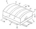
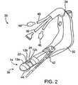
- FIG. 2is a perspective view of a simplified applicator encompassed by the present invention.
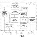
- FIG. 3schematically illustrates a cooling assembly encompassed by the present invention.
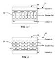
- FIGS. 4A and 4Dillustrate a heating element coupled to a distal portion of the applicator of FIG. 2 .
- FIGS. 4B and 4Care cross sectional views of the flow conduit along lines B-B and C-C.
- FIGS. 4E to 4Iillustrate a variety of different positions of the heating element(s) on the applicator.
- FIG. 5illustrates a looped path of a coolant through a distal portion of the applicator of FIG. 2 .
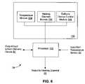
- FIG. 6schematically illustrates a control of the cooling assembly of FIG. 3 .
- FIG. 7schematically illustrates a method incorporated by the present invention.
- FIG. 8schematically illustrates a kit of the present invention.
- the present inventionprovides methods, devices, systems, controllers, and software algorithms for controlling a temperature of a tissue contacted by a surface of an applicator during delivery of a therapeutic energy to an underlying support tissue.
- the present inventionmay enhance the structural support provided by the support tissues by inducing controlled stiffening, contraction, or shrinkage of the structural support tissue, which are typically a collagenous tissue such as fascia, ligament, or the like.
- the present inventionis for treatment of urinary incontinence.
- the structural support tissuewill typically be part of a pelvic support system that is responsible in some manner for control of urination, or for supporting such a tissue.
- the tissues of the pelvic support systemgenerally maintain the position of the genitourinary tract, and particularly the position of urinary bladder, urethra, and the bladder neck coupling these structures.
- endopelvic fasciamay define a hammock-like structure, which extends laterally between the left and right arcus tendineus fasciae pelvis (ATFP). These tendon structures may extend substantially between the anterior and posterior portions of the pelvis, so that the endopelvic fascia EF at least partially defines the pelvic floor.
- AFParcus tendineus fasciae pelvis
- the fascial tissue of the pelvic support systemmay comprise tissues referred to under different names by surgeons of different disciplines, and possibly even by different practitioners within a specialty. In fact, some surgeons may assign a collagenous support structure of the endopelvic fascia one name when viewed from a superior approach, and a different name when viewed from an inferior approach. Some of the endopelvic fascia may comprise two collagenous layers with a thin muscular layer there between, or may comprise a single collagenous layer.
- the hammock-like endopelvic fascia described hereinmay be damaged or missing, particularly after pregnancy, so that the support of the genitourinary tract is instead provided by a variety of fascial layers, muscular tissues, ligaments, and/or tendons within the pelvis.
- the treatment of the present inventionmay be directed at a variety of tissue structures defining the pelvic floor and/or diaphragm including, but not limited to the ureter, the sphincter, pelvic ligaments, pelvic floor muscles, a suspension ligament (such as the anterior sacro-coccygeal ligament); arcus tendineus fasciae pelvis ATFP, the white line of the pelvis; fasciae of the obturator intemus muscle; the arcus tendineus levator ani or “picket fence” to the iliococcygeus portion of the levator ani muscle; bulbocavernosus muscle; ischiocavernosus muscle; urethrovaginal sphincter; m.
- tissue structures defining the pelvic floor and/or diaphragmincluding, but not limited to the ureter, the sphincter, pelvic ligaments, pelvic floor muscles, a suspension ligament (such as the anterior sacro-coccygeal ligament);
- structures of the bladder and urethraincluding but not limited to: urethral wall; urethrovesical fascia; bladder suspension ligaments; detrusor muscle; bladder neck; and the pubo-coccygeus muscle which relaxes to open the bladder neck, initiating micturation
- structures of the vaginaincluding: vagino-uterine fascia, lamina basement—the dense connective tissue layer just under the epithelium; pubo-urethral or puboprostatic ligaments; pubo-vesicle ligament and posterior pubo-urethral or puboprostatic ligament; pubovesicle muscle, a smooth muscle that is integrated with the pubovesicle ligament; and pubocervical fascia which attaches to the ATFP
- structures of the uterusincluding: round ligament; sacrouterine ligament; and broad ligament
- structures of the bowelincluding: rectal
- the endopelvic fasciaWhen the endopelvic fascia has excessive length or stretches excessively under a load, the fluid pressure within the bladder advances into the bladder neck and down the urethra more readily. Leakage may result in part because the endopelvic fascia allows the bladder, bladder neck, and/or urethra to drop below its desired position, at which fluid pressure within the bladder may actually help to seal the bladder neck. Stretching of the endopelvic fascia may also alter the timing of pressure pulse transmission to the urethra.
- the pressure in the urethraWhen a continent woman coughs, the pressure in the urethra will often increase more than one-tenth of a second prior to the increase in bladder pressure. In women with stress incontinence, the bladder pressure may rise first. For a continent woman having endopelvic fascia which stretches much less under the influence of a pressure pulse, the time delay between initiation of the pressure pulse and transferring sufficient force to the urethra to effect closure may therefore be significantly less. By treating the endopelvic fascia to decrease its length and/or increase its stiffness, the descent time of the pelvic viscera during a cough will be shorter than an untreated, excessively long and/or excessively elastic tissue.
- the support tissuemay be treated non-surgically or it may be accessed for direct treatment in a variety of ways.
- the surface of the endopelvic fascia(or other tissue) may be accessed transvaginally by forming and displacing a flap from the vaginal wall with the assistance of a weighted speculum.
- the endopelvic fasciamay be accessed laparoscopically.
- Tissue contraction or stiffeningresults from controlled heating of the tissue by affecting the collagen molecules of the tissue. Contraction occurs as a result of heat-induced uncoiling and repositioning of the collagen ⁇ -pleated structure. By maintaining the times and temperatures set forth below, significant tissue contraction can be achieved without substantial collateral tissue necrosis. Stiffening results from the loss of elasticity of the tissue due to the formation of scar tissue and/or attachment of adjacent support tissues to each other as a result of controlled heating of the tissue.
- the temperature of the target tissue structurewill generally be raised to a temperature in the range from about 60° C. to about 110° C., often being in the range from about 60° C. to about 80° C., preferably in the range from about 65° C. to about 75° C., and more preferably from about 69° C. to about 75° C. Such heating will generally be carried out for a period from about 30 seconds to about 5 minutes. These heating times will vary depending on the configuration of the electrodes, power source, target tissue, and the like.
- One exemplary method of controlling heating of the tissueis described in co-pending U.S. patent application Ser. No. 10/102,596, filed Mar. 19, 2002, the complete disclosure of which is incorporated herein by reference.
- the heatingmay effect a shrinkage of the target tissue in at least one dimension of between about 15 percent and 50 percent, and preferably at least about 40 percent.
- the temperature of the target tissue structurewill generally be raised to value in the range of about 45° C. to about 60° C. and will generally effect stiffening of the target tissue.
- the rise in temperaturemay be quite fast, although there will often be advantages in heating tissues more slowly, as this will allow sufficient heat to be removed from tissues which are not targeted for therapy, thereby minimizing collateral damage. However, if too little heating energy is absorbed by the tissue, blood perfusion will transfer the heat away from the targeted tissue, so that the temperature will not rise sufficiently to effect therapy.
- the total amount of energy deliveredwill depend in part on which tissue structure is being treated, how much tissue is disposed between the target tissue and the heating electrode(s), and the specific temperature and time selected for the protocol.
- the power deliveredwill often be in the range from about 2 W to about 100 W, usually being about 2 W to about 50 W, and preferably between about 12 W and 40 W.
- the poweris delivered in a range of about 12 W to about 15 W.
- dwelle.g., maintaining the tissue temperature above a target temperature for a desired time period
- the powermay be varied.
- the powermay initially be delivered in a range of about 15 W to about 20 W for a first time period, and thereafter delivered in a range of about 30 W to about 40 W for a second time period.
- the powermay be varied by ⁇ 0 W to ⁇ 10 W from the power level in the second time period so as to maintain the tissue temperature at a target temperature.
- the temperaturewill usually not drop instantaneously when the heating energy stops, so that the tissue may remain at or near the therapy temperature for a time from about 10 seconds to about 2 minutes, and will often cool gradually back to body temperature.
- treatment of other conditionsmay be effected by selective ablation, shrinking or stiffening of a wide variety of other tissues, including (but not limited to) the diaphragm, the abdominal wall, the breast supporting ligaments, the fascia and ligaments of the joints, the collagenous tissues of the skin, tumors, and the like.
- FIG. 1schematically illustrates a simplified system 10 of the present invention.
- System 10includes a tissue contacting surface 14 that includes at least in part a surface of electrode assembly 12 and spacers 44 around and/or between electrode assembly 12 ( FIG. 2 ).
- Electrode assembly 12can include one or more individual electrodes and may be positioned on a distal portion of an applicator body 32 ( FIG. 2 ).
- System 10may include a cooling assembly 16 that is in part positioned adjacent contact surface 14 so as to cool the tissue contacting surface 14 to a desired cooled temperature.
- a control 18may be coupled to a power source 20 , cooling assembly 16 , and electrode assembly 12 to control the therapeutic heating and cooling therapy.
- Control 18may comprise one or more processors and a memory for storing the software algorithms that are implemented by the present invention.
- System 10may optionally include one or more temperature sensor(s) 22 that are coupled to control 18 .
- Temperature sensor(s) 22may be attached to the applicator body and include one or more discrete temperature sensors, such as a thermocouple, that may be used to monitor a temperature of the intermediate tissue, target tissue, and/or contacting surface 14 . In other embodiments, however, temperature sensor 22 may be part of an assembly that is separate from the applicator body.
- At least one temperature sensor 22may be positioned on a needle 24 , such as a nitinol, stainless steel, composite, or polymer needle, that is deployable from the applicator body. If temperature sensor 22 is attached to needle 24 , system 10 may include a needle deployment device 26 to deploy the needle from a retracted position to a deployed position. Additionally or alternatively, temperature sensor(s) 22 can be attached directly to the applicator body so as to measure the temperature of the surface of the intermediate tissue and/or to monitor a temperature of the electrode surface. A complete description of one suitable temperature sensor is described in co-pending and commonly owned U.S. patent application Ser. No. 10/211,973, filed Aug. 1, 2002, the complete disclosure of which is incorporated herein by reference.
- FIG. 2illustrates one exemplary applicator 30 of the present invention that is used to deliver the therapeutic energy to the target tissue.
- the applicator 30generally includes an applicator body 32 having a proximal portion 34 (e.g., handle) and a distal portion 36 (e.g., applicator tip).
- Electrode assembly 12may include a plurality of electrodes 12 a , 12 b , 12 c attached to the distal portion 36 of applicator body 32 to deliver a therapeutic energy to the target tissue.
- a power sourcesuch as a high frequency power source (e.g., RF energy, microwave or the like).
- the power sourcemay be connected to control 18 ( FIG. 1 ) through connector 38 . It should be appreciated, however, that for ease of illustration three electrodes and one connector 38 are illustrated. However, the applicators 30 of the present invention may include any number of electrodes and connectors.
- applicator 30may optionally include a guide assembly 42 to assist in positioning electrodes 12 adjacent the target tissue within the patient's body.
- guide assembly 42may be found in co-pending and commonly owned U.S. patent application Ser. No. 09/991,368, filed Nov. 20, 2001 and U.S. patent application Ser. No. 10/301,561, filed on Nov. 20, 2002, the complete disclosures of which are incorporated herein by reference.
- Applicator body 32may also carry needle 24 for deployment into the patient's tissue.
- Needle 24typically carries one or more temperature sensors 22 . It should be appreciated, however, that needle 24 may carry an electrode, and/or the needle may be used for delivering a medicant, pharmacological agents, saline, fluids to enhance energy delivery, or the like.
- a more complete description of some exemplary applicators that can carry the needle 24 of the present inventionare described in commonly owned U.S. Pat. Nos. 6,035,238, 6,044,847, 6,091,995, 6,156,060, 6,139,569, 6,216,704, 6,236,891, 6,283,987, and 6,292,700, the complete disclosures of which are incorporated herein by reference.
- Electrode assembly 12 of the present inventionwill generally include a series of conductive surface segments which are aligned to define a substantially planar electrode surface.
- the electrode surface segmentsmay be separated by an electrically insulating material 44 , with the insulation being much smaller in surface area than the conductive segments.
- the electrodesmay be conductive areas on a flexible printed circuit assembly which are mounted on an insulating substrate.
- the substratemay be attached to the applicator body by pressure sensitive or thermo-set adhesives. This embodiment eliminates the costs and manufacturing difficulties associated with discrete insulating segments between the electrodes.
- electrodes 12may be rounded and/or covered by an insulating material to prevent concentrations of the electrical potential and injury to the engaged tissue surfaces.
- electrode assembly 12includes electrodes 12 a , 12 b , 12 c , each of which is electrically isolated from the other electrodes through an electrically insulating and thermally conductive space 44 . This allows each of the electrodes to be individually energized so as to selectively deliver heating energy to a specific portion of the target tissue. Electrodes 12 a , 12 b , and 12 c may comprise surfaces of separated segments of metalized or plated ceramic, metalized or plated polymer, electrically conductive polymer, plated aluminum, gold plated brass, gold plated copper, stainless steel, sintered metal, or the like.
- electrode assembly 12 of the present inventionis generally herein described with reference to a linear array geometry
- the present inventionalso encompasses electrodes which are segmented into two-dimensional arrays, electrodes that are rotatable, non-linear electrode assemblies, curved electrodes, ribbed electrodes, electrodes positioned on a needle array, or the like.
- a more detailed description of a needle electrode arrayis described in U.S. Provisional Application No. 60/440,711, filed Jan. 16, 2003, the complete disclosure of which is incorporated herein by reference.
- the electrode surfaceswill preferably be separated by a gap which is less than a width (and length) of the electrodes.
- one electrode structuremay be disposed within a large body cavity such as the rectum or vagina, while the other is placed in an adjacent cavity, or on the skin so that the region to be treated is between the electrode surfaces.
- one or both electrodesmay be inserted and positioned laparoscopically. It will often be desirable to clamp the tissue tightly between the electrodes to minimize the gap therebetween, and to promote efficient coupling of the electrode to the tissue.
- electrodes 12 a , 12 b , 12 care energized by a radiofrequency (RF) power source 20 .
- RFradiofrequency
- Multiplexersmay be used with control 18 to individually energize each electrode, typically varying the power or time each segment is energized to more nearly uniformly heat fascia or other target tissue.
- the use of a radiofrequency current of relatively low voltagehelps to avoid arcing and damage to the intermediate tissue in direct contact with electrodes 12 .
- sufficient heatingcan be provided by a current of between about 0.2 amps and 2.0 amps, preferably about 1.0 amp, and a maximum voltage of between about 30 and 100 volts rms., preferably being about 60 volts rms.
- Each electrodewill often have a surface area of between about 0.5 cm 2 and 200 cm 2 , and the current density in the target tissue will often be between about 1 mA/cm 2 and 4 A/cm 2 , preferably being between about 5 mA/cm 2 and 500 mA/cm 2 .
- Thiscan provide a maximum power in the range from about 10 W to about 200 W, often being about 30 W.
- electrode 12is lifted away from the intermediate tissue, there will typically be no arcing. Instead, the current will simply stop. This highlights the difference between the electrical tissue heating of the present invention and other conventional electrosurgical techniques.
- contacting surfaces 14 of the applicatorsuch as electrode surface and other insulating surfaces on the distal portion of the applicator 30 may be cooled with cooling assembly 16 ( FIG. 1 ), such as a phase-change heat exchanger that is disposed within the applicator.
- FIG. 3schematically illustrates one cooling assembly 16 that is encompassed by the present invention.
- the cooling assembly of FIG. 3is merely an example, and other cooling systems that have more or less elements are also encompassed by the present invention.
- Cooling assembly 16typically cools an area which extends beyond the energized electrode surface to prevent the formation of any hot spots adjacent the tissue surface, and to maximize the heat removal from intermediate tissue without chilling it to or below temperatures that irreversibly damages the tissue, such as might occur when freezing the tissue.
- Cooling assembly 16may include a coolant reservoir 50 coupled to a conduit 40 which extends through the distal portion 36 of the applicator. Cooling assembly may optionally include a coolant delivery device 52 that assists in delivering the coolant into the distal portion of the applicator and/or a return device 53 to assist in returning the coolant from the distal portion 36 back to reservoir 50 .
- Delivery device 52is typically in the form of a rotary pump, such as the Tuthill Corporation volumetric gear pump (12 vdc, 0.1 CC per revolution), vane, and the like.
- a return device 53are typically in the form of a Tecumseh refrigeration compressor (AEA Series), diaphragm, or piston pump and the like.
- a preferred embodiment of the present inventionuses the fact that the temperature of the reservoir determines the pressure of the cooling fluid.
- the temperature of the reservoirdetermines the pressure of the cooling fluid.
- sufficient pressuremay be achieved to reliably deliver the coolant to the applicator without the need for delivery device 52 .
- typical fluid delivery pressureis between about 65 psi to about 75 psi.
- Increasing the reservoir temperature to between about 40° C. to 45° C.raises the delivery pressure to between about 90 psi to about 95 psi and ensure that the R134a material remains in liquid form all the way to the applicator.
- the R134aUpon reaching the applicator, the R134a begins to transition to the gas phase. This occurs only when it moves from the delivery conduit out into a channel within the distal portion of the applicator. In embodiments where a compressor return device is used may lead to formation of some gas on the inlet side of the compressor which may lead to periodic variations in the gas flow rate which adversely affect the temperature stability of the coolant, and hence the temperature stability of the contact surface.
- Coolant delivery device 52 or the temperature of the reservoirmay be controlled by control 54 or by master control 18 ( FIG. 1 ).
- the control of reservoir temperature or pump speedmay be achieved by adding a pressure sensor 51 which allows the control 54 to monitor pressure and adjust the amount of power delivered to strip heating elements 57 mounted on the side of the reservoir 50 .
- the reservoirmay be placed within a closed oven like chamber whose temperature is regulated to achieve the desired delivery pressure.
- a weir-style bottom draining vapor/liquid separation devicemay be employed down-stream from the pumping devices to provide, to the applicator body a substantially higher percentage of liquid.
- One or more temperature sensors 22may be coupled to control 54 and positioned adjacent the contact surface 14 of applicator 30 to measure the temperature of the contact surface 14 and/or the intermediate tissue.
- one or more heating elements 56may be activated or deactivated by control 54 so that the temperature of the contact surface/intermediate tissue is within a desired temperature range.
- one or more temperature sensorssuch as a thermocouple (not shown), may be attached to a deployable needle and may also be in communication with control 54 so as to provide temperature information about the target tissue.
- coolants for circulation through conduit 40 in applicator 30may be used with the present invention.
- the selected coolantshould be non toxic and should provide an efficient cooling effect at low flow rates.
- Some coolants that are suitable for use in applicator 30include, but are not limited to, RB 276, nitrogen, R420A, R417a, propane, CO 2 , R134a refrigerant, mixtures of various other coolants, fluids, and the like.
- conduit 40defines a flow path between a cooling inflow port 46 and a cooling outflow port 48 , in which coolant from reservoir 50 and delivery device 52 is cycled through applicator 30 and returned to the coolant reservoir 50 using an optional return device 53 .
- the returning coolantmay flow through outflow port 48 and/or be optionally treated through an adsorption, filtration and/or catalytic system 61 , and thereafter be allowed to escape to the atmosphere, within the control system through an exhaust control valve 55 .
- the coolant flow ratemay be chosen to be substantially constant, or the coolant flow rate may be chosen to be variable during the therapeutic treatment. While a temperature of the contact surface may be monitored and the coolant flow rate may be varied to compensate for the temperature fluctuations at the contact surface, Applicants have found that a delivery device provides a substantially constant coolant flow rate (with local heating of the coolant at the distal portion of applicator 30 using one or more heating elements 56 ) achieves superior cooling for a number of reasons.
- the local heating of a constant flowing coolant using a local heating elementprovides (1) a solid state heating element that results in increased reliability versus a mechanical valve, (2) the solid state heating element requires less volume and is noiseless (versus an audible clicking of the valve, (3) provides a more rapid response of a “locally” controlled heat exchange via a resistive heating element than a remotely controlled valve which is as far away as 5′ to 10′, (4) the local heating element induces a temperature variation in the cooling chamber in as quickly as 0.5 second whereas a remote valve changing coolant flow rate would result in 5 to 20 seconds of control delay due to the extremely low coolant flow rates, and (5) the local heating element(s) 56 reduce temperature distribution variations across the applicator.
- one or more local heating elements 56are coupled to the distal portion 36 of the applicator body 32 .
- Heating element 56may be coupled to a power source through one or more connector wires 60 .
- a power between about 30 watts and about 45 wattsmay be delivered over connector wires 60 to energize the heating element 56 .
- the heating element(s) 56are typically attached to the applicator body opposite of the contact surface (e.g., bottom surface) or positioned in a slot on the applicator body. For example, as shown in FIGS.
- a single embedded resistive heating elementmay be used to locally heat the distal portion 36 of applicator 30 and the returning coolant.
- the heating element 56may be any shape and size, but is typically a flat profile power resistor.
- the heating elementis a power film resistor, such as the Caddock mp725 or Caddock mp850, which delivers a power of 40 watts at 36 volts.
- FIGS. 4D , 4 E, and 4 Fillustrate some useful examples of a placement of the heating element(s) 56 on or within the distal portion 36 of applicator body 32 which balance a temperature variation across the applicator body that is caused by the flow pattern of the coolant.
- a single resistive heating element 56may be symmetrically mounted about a center point 59 beneath the contact surface 14 (e.g., electrode surface and insulator surfaces) of the distal portion 36 of applicator body 32 .
- a temperature variation on the contact surfacewill be about 5 degrees Celsius or less.
- the heating element 56may be mounted “off-center” of a middle point 59 of the contact surface 14 of distal portion 36 in the applicator body 32 .
- the contact surfaceis about 30 mm long and the heating element 56 was moved proximally about 3 mm off the center point 59 .
- Such an embodimentreduces the temperature variation across the contact surface to less than about 2 degrees Celsius.
- the present inventionis not limited to only one heating element 56 .
- An array of small wattage heating elements 56may be positioned in such a way as to reduce the spatial temperature distribution across the applicator body contact surface as a result of coolant flow through the applicator.
- FIGS. 4G to 4Iillustrate some illustrative examples of an array of resistive heating elements 56 that may be used with the applicators 30 of the present invention.
- an array of two resistive heating elements 56 , 56 ′are positioned beneath the contact surface 14 in the distal portion 36 of the applicator body 32 so as to evenly distribute heat and reduce the temperature variation across the contact surface.
- Some useful resistive heating elementsare the Caddock mp821 series which can deliver 20 watts at 14 volts across each 10 ⁇ resistive heating element.
- the resistive heating elements 56 , 56 ′may be evenly spaced about a center point 59 of the contact surface or heating elements 56 , 56 ′ may be mounted off centered about center point 59 so as to provide more even cooling across the contact surface. For example, as illustrated in FIG.
- heating element 56 ′is mounted about 1.5 mm farther from the center point 59 than heating element 56 .
- the temperature variationmay be reduced to 1 degree Celsius or less.
- heating element 56 ′instead of moving heating element 56 ′ to an off-centered position, it may be possible to provide a resistance differential between heating elements 56 , 56 ′ so that there is more heating adjacent the proximal end 31 .
- each of heating elements 56 , 56 ′may be coupled to a same or different power source and may deliver the same heat or different heat. If heating elements 56 , 56 ′ provide different heat, heating element 56 ′ will typically deliver more heat so as to better counter the greater cooling effect at the entry point of the coolant.
- an eight resistor array of 5 watt power resistorsmay be spaced within the distal portion 36 of applicator body 32 to permit a plurality of heating points so as to further reduce the spatial temperature distribution across the contact surface. Applicants have found that by distributing a plurality of heating elements 56 through the applicator body 32 , the temperature variation may be reduced to less than about 1 degree Celsius to about 2 degrees Celsius.
- each of the heating elements 56may be configured to have the same wattage (e.g., 5 W) or the resistors could be configured to have different wattages.
- the heating elements R 1 , R 2 , . . . R 8are coupled in series to a single power source.
- the heating elementsmay have different resistance values so as to deliver a differential heating to the different portions of the distal portion 36 .
- R 1 and R 2may have a resistance value of 2.0 ⁇
- R 3 -R 6may have a resistance value of 2.5 ⁇
- R 7 and R 8may have a resistance value of 3 ⁇ .
- the distal portion 36has a length of about 30.0 mm and the heating elements are about 5 mm wide by 10 mm long.
- Such a configurationprovides a common excitation voltage while providing a tailored heating profile to compensate for the natural heat distribution across the distal portion 36 .
- the resistive heating elementsmay be positioned in a serpentine configuration such that R 1 , R 2 , . . . R 9 are strategically dispersed over the distal portion.
- a constant voltageis applied and different resistance values are provided in the heating elements to cause the variable heating profile.
- One useful examplehas R 1 , R 2 , and R 3 with a resistance value of 2 ⁇ , R 4 , R 5 , and R 6 with a resistance value of 2.5 ⁇ , and R 6 , R 7 , and R 8 with a resistance value of 3 ⁇ .
- such a configurationprovides greater local heating adjacent proximal end 31 so as to better counter the greater cooling effect at the entry point of the coolant.
- FIGS. 4A to 4Iare merely illustrative and should not limit the scope of the present invention.
- the present inventionmay use as many heating elements as desired and may use a variety of different resistance values to provide different heating energy.
- the flow rate of the coolantwill vary depending on the temperature of the coolant, the type of coolant used, the desired temperature at the contact surface, the type of procedure being performed, or the like.
- the coolant flowshould also be selected to be great enough to accommodate all of the anticipated heat loads during the heat treatment.
- the flow rate of the coolantis typically between about 5 and about 25 grams per second, and preferably between about 15 and about 20 grams per second.
- Such flow ratesare chosen such that at the chosen flow rate the coolant is able to compensate for the maximum RF heating power levels.
- the flow ratemay be higher or lower.
- FIGS. 5 , 4 B, and 4 Cillustrate two configurations of a coolant flow that are encompassed by the present invention. As can be appreciated, such configurations are merely examples and should not be construed to limit the scope of the present invention. While only one heating element 56 is illustrated in FIG. 5 , it should be appreciated that any number of heating elements 56 may be used and the heating elements 56 may be placed in a variety of different patterns so as to provide substantially even cooling over the contact surface 14 .
- the pathenters the distal portion and loops back around from the end and exits the distal portion as the outflow port 48 . While such a loop configuration provides adequate cooling, the cooling is slightly asymmetrical across the electrode surface—about a 5° C. differential across the contact surface between the point where the coolant enters the distal portion and the point where the coolant exits the distal portion.
- conduit 40takes on the form of a serpentine path in which coolant is delivered through the distal portion 36 so as to substantially evenly control the temperature differential over the contact surface.
- the coolantis delivered into a left and right conduit simultaneously and the coolant is flowed in a zig-zag or serpentine pattern toward the middle of the applicator body where coolant exits the distal portion of the applicator body.
- a serpentine conduit configuration in combination with appropriately positioned heating element(s)provide an improved method of evenly cooling the contact surface.
- the coolantmaintains a cooled tissue region on and around each electrode surface 14 below a maximum safe tissue temperature, typically being below about 45° C., and preferably between approximately 0° C. and about 40° C.
- a maximum safe tissue temperaturetypically being below about 45° C., and preferably between approximately 0° C. and about 40° C.
- the contact surfaceis typically cooled to a temperature between about ⁇ 5° C. and about 3° C., and preferably about ⁇ 2° C.
- FIG. 6illustrates one embodiment of control 54 that controls the cooling algorithm of the present invention.
- Control 54will typically include a processor 102 that is adapted to run a computer cooling algorithm stored in software modules 104 , 106 , 108 that are in a memory or other computer readable medium 109 that is accessible by the processor 102 of control 54 .
- the computer readable mediummay take the form of a hard drive, optical drive, such as a CD-ROM, or the any other conventional computer-readable medium.
- the illustrated code modulesare merely illustrative, and the present invention may comprise a variety of other code modules for performing other aspects of the present invention.
- control 54may include hardware modules or a combination of software and hardware to carry out the methods of the present invention.
- Processor 102will be in communication with temperature sensors 22 , and may send control signals to direct the flow of the coolant in delivery device 52 and the power delivered to heating element 56 . Such parameters are typically based at least in part on a temperature signal sensed by temperature sensors 22 . In some embodiments, delivery of the coolant may be manually controlled by the user, if desired. In such embodiments, controller will not have a module for controlling the delivery of the coolant.
- the temperature sensingmay be provided using temperature sensors positioned on the distal end 36 of the catheter body (not shown) and/or needle 24 that carries one or more temperature sensors 22 ( FIG. 2 ). Temperature sensor 22 may sense the temperature of the electrodes, the target tissue, the tissue at the tissue/electrode interface, and/or the intermediate tissue.
- a temperature of the target tissue and/or the intermediate tissuemay be monitored before the delivery of energy and during the delivery of energy using one or more temperature sensors on the applicator body and/or a needle assembly carrying one or more temperature sensors.
- the needlecan carry other sensors to monitor other characteristics of the tissue, and the temperature of the coolant may be based on such measured characteristics.
- Temperatureis measured via a thermocouple or RTD sensor that is positioned on or along an electrode surface.
- a higher than desired temperatureis adjusted by limiting power supplied to the resistive heating element so as to allow the constantly flowing coolant to lower the temperature to the desired level.
- An under temperature conditionis controlled by raising the power supplied to the resistive heating element so as to heat the distal end of the applicator and/or constantly flowing coolant to a higher temperature, and thus raise the temperature of the tissue contacting surface 14 and/or intermediate tissue.
- the amount of power, (wattage) supplied to the resistive heatermay be adjusted either by varying voltage, current, or total power-on via pulsed relay to control % power supplied.
- FIG. 7illustrates one method that may be carried out by the control 54 of FIG. 6 or other controls configured to carry out the methods of the present invention.
- a delivery devicemoves the coolant from a coolant reservoir and through the fluid conduit in the applicator.
- the flow rate of the coolantmay be monitored by processor 102 and displayed on a display on a console or on the applicator.
- the parameters of the coolant temperature and coolant flow ratemay be automatically controlled by delivery device control module 108 being run by processor 102 .
- the coolant temperature and flow ratemay be manually controlled by a user with a mechanical device, such as a valve.
- the coolant flowPrior to use on the patient, the coolant flow is started by switch or other input device from the physician (step 190 ).
- the systemmeasures the temperature of the contact surface using a temperature sensor just below the contact surface (step 192 ).
- the temperatureis at or near room temperature and the control is delivering no power to the counter heating resistor(s).
- the counter heating resistor(s)start to receive power to bring the final temperature smoothly to the set point value. If the set point value range is not met, the energy delivered to the heating resistor is adjusted (step 194 ).
- the physicianmay perform a test of the needle thermocouple.
- One method of testing the thermocoupleis by extending the needle. The controller then looks for a temperature rise in the thermocouple within the needle as the needle moves into the room temperature air. If this test passes, a further test is made by applying low level RF power to the applicator electrodes while the applicator is still in air to make sure that the electrodes are properly connected. If the cool down tests are not complete, steps 192 and 194 are repeated. Once these cool down tests are complete (the cooling control system remains operational throughout these tests) the physician then places the contact surfaces of the applicator 30 against the intermediate tissue (step 200 ).
- the distal portion of the applicatoris inserted transvaginally and placed against the intermediate tissue in the vagina.
- the coolant flowmay optionally be used to pre-cool the intermediate tissue according to a predetermined pre-cooling regimen (step 202 ).
- the coolantis delivered from the coolant reservoir and to the applicator through conduit 40 (step 201 ).
- the temperature of the intermediate tissue and/or the contact surfacesmay be measured to determine if the temperatures are within a desired range (step 203 ). If adjustments to the temperature are needed, energy may be delivered to one or more heating elements 56 to bring the measured temperatures to the desired range (step 204 ).
- no pre-coolingmay be performed, and the coolant may be flowed through the conduit 40 only during the delivery of the therapeutic heating energy (steps 205 , described below).
- Control 18may run a variety of pre-treatment tests on the applicator 30 to ensure that the proper conditions for the procedure are present. For example, as described in co-pending, commonly owned U.S. patent application Ser. No. 10/768,780, entitled “Heating Method for Tissue Contraction”, filed concurrently herewith (the complete disclosure of which is incorporated herein by reference), the control may test the tissue impedance to ensure that the electrodes are properly contacting the intermediate tissue.
- the coolant flowmay be started (or maintained—if pre-cooling is performed) (step 205 ).
- the energy delivered to the heating elementmay be automatically reduced by control 54 , since the energy delivered to electrodes tends to increase a temperature of the contact surface (e.g., electrodes 12 ) (step 206 ).
- the temperature of the intermediate tissue, target tissue, and/or contact surfaces of the applicatormay be measured by one or more temperature sensors (step 207 ).
- the temperature signalmay be processed at the processor 102 by temperature module 104 .
- the processordetermines if the intermediate tissue and/or contact surface of the applicator are within a desired temperature range. If the measured temperature is within the desired temperature range, the processor will typically not change any aspects of the cooling regimen. If however, the measured temperature(s) are not within the desired temperature range, processor 102 may send a signal to heating element 56 and/or delivery device 52 to change aspects of the cooling program to bring the temperature to within the desired range.
- the processormay send a signal to adjust a flow rate of the coolant, a signal to globally change a temperature of the coolant, or a signal to locally change of the temperature of the coolant by adjusting the delivery of energy to a heating element.
- the monitoring of the temperature and the local adjustment of the temperature of the coolantmay be repeated until the therapeutic heating is complete.
- FIG. 8illustrates a kit according to an embodiment of the present invention.
- the kitmay include an applicator 30 and instructions for use 300 , and one or more packages 302 .
- Applicator 30will generally be as described above, and the instruction for use (IFU) 300 will set forth any of the methods described above.
- Package 302may be any conventional medical device packaging, including pouches, trays, boxes, tubes, or the like.
- the instructions for use 300will usually be printed on a separate piece of paper, but may also be printed in whole or in part on a portion of the package 302 .
- the kitmay include one or more controllers 18 , 54 and/or a power source 30 .
- the coolantmay be heated prior to entering the applicator or heating the coolant to a desired temperature while still in the coolant reservoir.
Landscapes
- Health & Medical Sciences (AREA)
- Surgery (AREA)
- Engineering & Computer Science (AREA)
- Life Sciences & Earth Sciences (AREA)
- Biomedical Technology (AREA)
- Molecular Biology (AREA)
- Nuclear Medicine, Radiotherapy & Molecular Imaging (AREA)
- Plasma & Fusion (AREA)
- Physics & Mathematics (AREA)
- Heart & Thoracic Surgery (AREA)
- Medical Informatics (AREA)
- Otolaryngology (AREA)
- Animal Behavior & Ethology (AREA)
- General Health & Medical Sciences (AREA)
- Public Health (AREA)
- Veterinary Medicine (AREA)
- Surgical Instruments (AREA)
- Thermotherapy And Cooling Therapy Devices (AREA)
Abstract
Description
Claims (31)
Priority Applications (3)
| Application Number | Priority Date | Filing Date | Title |
|---|---|---|---|
| US10/768,778US7476242B2 (en) | 2004-01-30 | 2004-01-30 | Electrically heated/phase change probe temperature control |
| PCT/US2005/003527WO2005074648A2 (en) | 2004-01-30 | 2005-01-28 | Methods and devices for controlling a temperature of an applicator body |
| AU2005209924AAU2005209924B2 (en) | 2004-01-30 | 2005-01-28 | Methods and devices for controlling a temperature of an applicator body |
Applications Claiming Priority (1)
| Application Number | Priority Date | Filing Date | Title |
|---|---|---|---|
| US10/768,778US7476242B2 (en) | 2004-01-30 | 2004-01-30 | Electrically heated/phase change probe temperature control |
Publications (2)
| Publication Number | Publication Date |
|---|---|
| US20050171582A1 US20050171582A1 (en) | 2005-08-04 |
| US7476242B2true US7476242B2 (en) | 2009-01-13 |
Family
ID=34807950
Family Applications (1)
| Application Number | Title | Priority Date | Filing Date |
|---|---|---|---|
| US10/768,778Expired - LifetimeUS7476242B2 (en) | 2004-01-30 | 2004-01-30 | Electrically heated/phase change probe temperature control |
Country Status (3)
| Country | Link |
|---|---|
| US (1) | US7476242B2 (en) |
| AU (1) | AU2005209924B2 (en) |
| WO (1) | WO2005074648A2 (en) |
Cited By (11)
| Publication number | Priority date | Publication date | Assignee | Title |
|---|---|---|---|---|
| US20090149930A1 (en)* | 2007-12-07 | 2009-06-11 | Thermage, Inc. | Apparatus and methods for cooling a treatment apparatus configured to non-invasively deliver electromagnetic energy to a patient's tissue |
| US20090270954A1 (en)* | 2008-04-28 | 2009-10-29 | Thermage, Inc. | Methods and apparatus for predictively controlling the temperature of a coolant delivered to a treatment device |
| US20090318851A1 (en)* | 2008-06-19 | 2009-12-24 | Thermage, Inc. | Leakage-resistant tissue treatment apparatus and methods of using such tissue treatment apparatus |
| US20100049186A1 (en)* | 1997-08-13 | 2010-02-25 | Ams Research Corporation | Noninvasive devices, methods, and systems for shrinking of tissues |
| US20100114087A1 (en)* | 1998-02-19 | 2010-05-06 | Edwards Stuart D | Methods and devices for treating urinary incontinence |
| WO2011084957A1 (en) | 2010-01-05 | 2011-07-14 | Curo Medical, Inc. | Medical heating device and method with self-limiting electrical heating element |
| US8403927B1 (en) | 2012-04-05 | 2013-03-26 | William Bruce Shingleton | Vasectomy devices and methods |
| US20150231329A1 (en)* | 2005-09-29 | 2015-08-20 | Deka Products Limited Partnership | Method and System for Shape-Memory Alloy Wire Control |
| US9345614B2 (en) | 2014-07-25 | 2016-05-24 | Cascade Wellness Technologies, Inc. | Thermal contrast therapy devices, methods and systems |
| US11395692B2 (en)* | 2018-08-31 | 2022-07-26 | Bausch Health Ireland Limited | Methods and apparatus for pumping coolant to an energy delivery device |
| US12274857B2 (en) | 2006-02-09 | 2025-04-15 | Deka Products Limited Partnership | Method and system for shape-memory alloy wire control |
Families Citing this family (64)
| Publication number | Priority date | Publication date | Assignee | Title |
|---|---|---|---|---|
| US7674259B2 (en)* | 2000-12-09 | 2010-03-09 | Tsunami Medtech | Medical instruments and techniques for thermally-mediated therapies |
| US8016823B2 (en) | 2003-01-18 | 2011-09-13 | Tsunami Medtech, Llc | Medical instrument and method of use |
| US7892229B2 (en) | 2003-01-18 | 2011-02-22 | Tsunami Medtech, Llc | Medical instruments and techniques for treating pulmonary disorders |
| US7549987B2 (en)* | 2000-12-09 | 2009-06-23 | Tsunami Medtech, Llc | Thermotherapy device |
| US9433457B2 (en) | 2000-12-09 | 2016-09-06 | Tsunami Medtech, Llc | Medical instruments and techniques for thermally-mediated therapies |
| US8444636B2 (en) | 2001-12-07 | 2013-05-21 | Tsunami Medtech, Llc | Medical instrument and method of use |
| US8579892B2 (en) | 2003-10-07 | 2013-11-12 | Tsunami Medtech, Llc | Medical system and method of use |
| MX2007005937A (en) | 2004-11-16 | 2007-09-11 | Robert L Barry | Device and method for lung treatment. |
| US20070032785A1 (en) | 2005-08-03 | 2007-02-08 | Jennifer Diederich | Tissue evacuation device |
| US8852184B2 (en)* | 2005-09-15 | 2014-10-07 | Cannuflow, Inc. | Arthroscopic surgical temperature control system |
| US20070078502A1 (en)* | 2005-10-05 | 2007-04-05 | Thermage, Inc. | Method and apparatus for estimating a local impedance factor |
| US8702691B2 (en)* | 2005-10-19 | 2014-04-22 | Thermage, Inc. | Treatment apparatus and methods for delivering energy at multiple selectable depths in tissue |
| WO2007092610A2 (en)* | 2006-02-07 | 2007-08-16 | Tivamed, Inc. | Vaginal remodeling device and methods |
| US7993323B2 (en)* | 2006-11-13 | 2011-08-09 | Uptake Medical Corp. | High pressure and high temperature vapor catheters and systems |
| US8216218B2 (en)* | 2007-07-10 | 2012-07-10 | Thermage, Inc. | Treatment apparatus and methods for delivering high frequency energy across large tissue areas |
| EP2190373B1 (en) | 2007-08-23 | 2013-01-09 | Aegea Medical, Inc. | Uterine therapy device |
| US8322335B2 (en) | 2007-10-22 | 2012-12-04 | Uptake Medical Corp. | Determining patient-specific vapor treatment and delivery parameters |
| US8147532B2 (en)* | 2007-10-22 | 2012-04-03 | Uptake Medical Corp. | Determining patient-specific vapor treatment and delivery parameters |
| EP2080483B1 (en)* | 2008-01-17 | 2013-06-05 | Biotronik CRM Patent AG | Ablation catheter assembly and cooling control |
| US9924992B2 (en) | 2008-02-20 | 2018-03-27 | Tsunami Medtech, Llc | Medical system and method of use |
| US8721632B2 (en) | 2008-09-09 | 2014-05-13 | Tsunami Medtech, Llc | Methods for delivering energy into a target tissue of a body |
| US8579888B2 (en) | 2008-06-17 | 2013-11-12 | Tsunami Medtech, Llc | Medical probes for the treatment of blood vessels |
| US8121704B2 (en)* | 2008-06-19 | 2012-02-21 | Thermage, Inc. | Leakage-resistant tissue treatment apparatus and methods of using same |
| US10064697B2 (en) | 2008-10-06 | 2018-09-04 | Santa Anna Tech Llc | Vapor based ablation system for treating various indications |
| US9561066B2 (en) | 2008-10-06 | 2017-02-07 | Virender K. Sharma | Method and apparatus for tissue ablation |
| US10695126B2 (en) | 2008-10-06 | 2020-06-30 | Santa Anna Tech Llc | Catheter with a double balloon structure to generate and apply a heated ablative zone to tissue |
| US9700365B2 (en) | 2008-10-06 | 2017-07-11 | Santa Anna Tech Llc | Method and apparatus for the ablation of gastrointestinal tissue |
| US9561068B2 (en) | 2008-10-06 | 2017-02-07 | Virender K. Sharma | Method and apparatus for tissue ablation |
| US11284931B2 (en) | 2009-02-03 | 2022-03-29 | Tsunami Medtech, Llc | Medical systems and methods for ablating and absorbing tissue |
| BR112012006059B8 (en)* | 2009-09-18 | 2021-06-22 | Viveve Inc | apparatus and system for remodeling a therapeutic zone in the tissue underlying a mucosal epithelium of female genital tissue |
| US8900223B2 (en) | 2009-11-06 | 2014-12-02 | Tsunami Medtech, Llc | Tissue ablation systems and methods of use |
| US9161801B2 (en) | 2009-12-30 | 2015-10-20 | Tsunami Medtech, Llc | Medical system and method of use |
| US9943353B2 (en) | 2013-03-15 | 2018-04-17 | Tsunami Medtech, Llc | Medical system and method of use |
| ES2912362T3 (en) | 2010-11-09 | 2022-05-25 | Aegea Medical Inc | Method of placement and apparatus for delivering steam to the uterus |
| CA2851355C (en) | 2011-10-07 | 2020-02-18 | Aegea Medical Inc. | Integrity testing method and apparatus for delivering vapor to the uterus |
| WO2013136312A2 (en)* | 2012-03-15 | 2013-09-19 | Krishnan Subramaniam Chitoor | Mechanism, system, method for in vivo lead fixation |
| CN105919666A (en) | 2012-03-16 | 2016-09-07 | 女康乐公司 | Therapy equipment for repairing female vaginal tissue |
| EP3964151A3 (en) | 2013-01-17 | 2022-03-30 | Virender K. Sharma | Apparatus for tissue ablation |
| AU2014240225A1 (en) | 2013-10-01 | 2015-04-16 | Uptake Medical Technology Inc. | Preferential volume reduction of diseased segments of a heterogeneous lobe |
| US10179019B2 (en) | 2014-05-22 | 2019-01-15 | Aegea Medical Inc. | Integrity testing method and apparatus for delivering vapor to the uterus |
| EP3145425B1 (en) | 2014-05-22 | 2024-10-23 | CooperSurgical, Inc. | Systems for performing endometrial ablation |
| US10485604B2 (en) | 2014-12-02 | 2019-11-26 | Uptake Medical Technology Inc. | Vapor treatment of lung nodules and tumors |
| US10531906B2 (en) | 2015-02-02 | 2020-01-14 | Uptake Medical Technology Inc. | Medical vapor generator |
| US20210169566A1 (en)* | 2019-12-04 | 2021-06-10 | National University Of Ireland, Galway | Devices for therapeutic nasal neuromodulation and associated methods and systems |
| US12268433B2 (en) | 2015-05-12 | 2025-04-08 | National University Of Ireland, Galway | Devices for therapeutic nasal neuromodulation and associated methods and systems |
| WO2016183337A2 (en) | 2015-05-12 | 2016-11-17 | National University Of Ireland Galway | Devices for therapeutic nasal neuromodulation and associated methods and systems |
| EP3416551B1 (en) | 2016-02-19 | 2022-10-12 | Aegea Medical Inc. | Apparatus for determining the integrity of a bodily cavity |
| US12364537B2 (en) | 2016-05-02 | 2025-07-22 | Santa Anna Tech Llc | Catheter with a double balloon structure to generate and apply a heated ablative zone to tissue |
| US11331140B2 (en) | 2016-05-19 | 2022-05-17 | Aqua Heart, Inc. | Heated vapor ablation systems and methods for treating cardiac conditions |
| EP3576690A1 (en)* | 2017-01-31 | 2019-12-11 | Viveve Inc. | Devices for dual mechanism aesthetic treatment and methods of use thereof |
| US11896823B2 (en) | 2017-04-04 | 2024-02-13 | Btl Healthcare Technologies A.S. | Method and device for pelvic floor tissue treatment |
| US11129673B2 (en) | 2017-05-05 | 2021-09-28 | Uptake Medical Technology Inc. | Extra-airway vapor ablation for treating airway constriction in patients with asthma and COPD |
| US11344364B2 (en) | 2017-09-07 | 2022-05-31 | Uptake Medical Technology Inc. | Screening method for a target nerve to ablate for the treatment of inflammatory lung disease |
| US11350988B2 (en) | 2017-09-11 | 2022-06-07 | Uptake Medical Technology Inc. | Bronchoscopic multimodality lung tumor treatment |
| USD845467S1 (en) | 2017-09-17 | 2019-04-09 | Uptake Medical Technology Inc. | Hand-piece for medical ablation catheter |
| US11419658B2 (en) | 2017-11-06 | 2022-08-23 | Uptake Medical Technology Inc. | Method for treating emphysema with condensable thermal vapor |
| US11490946B2 (en) | 2017-12-13 | 2022-11-08 | Uptake Medical Technology Inc. | Vapor ablation handpiece |
| EP3801324B1 (en) | 2018-06-01 | 2025-05-28 | Aqua Medical, Inc. | Vapor generation and delivery systems |
| AU2019204574A1 (en) | 2018-06-27 | 2020-01-23 | Viveve, Inc. | Methods for treating urinary stress incontinence |
| US11547473B2 (en) | 2018-12-11 | 2023-01-10 | Neurent Medical Limited | Systems and methods for therapeutic nasal neuromodulation |
| US11653927B2 (en) | 2019-02-18 | 2023-05-23 | Uptake Medical Technology Inc. | Vapor ablation treatment of obstructive lung disease |
| WO2021205229A1 (en) | 2020-04-09 | 2021-10-14 | Neurent Medical Limited | Systems and methods for improving sleep with therapeutic nasal treatment |
| US11896818B2 (en) | 2020-04-09 | 2024-02-13 | Neurent Medical Limited | Systems and methods for therapeutic nasal treatment |
| EP3906878A1 (en)* | 2020-05-07 | 2021-11-10 | Gyrus ACMI, Inc. d/b/a Olympus Surgical Technologies America | Electro-surgical device with stable jaw temperature |
Citations (33)
| Publication number | Priority date | Publication date | Assignee | Title |
|---|---|---|---|---|
| US3298371A (en)* | 1965-02-11 | 1967-01-17 | Arnold S J Lee | Freezing probe for the treatment of tissue, especially in neurosurgery |
| US3948269A (en)* | 1973-08-31 | 1976-04-06 | Dragerwerk Aktiengesellschaft | Cryomedical device |
| US5758505A (en)* | 1995-10-12 | 1998-06-02 | Cryogen, Inc. | Precooling system for joule-thomson probe |
| US5769880A (en)* | 1996-04-12 | 1998-06-23 | Novacept | Moisture transport system for contact electrocoagulation |
| US5957920A (en) | 1997-08-28 | 1999-09-28 | Isothermix, Inc. | Medical instruments and techniques for treatment of urinary incontinence |
| US6035238A (en) | 1997-08-13 | 2000-03-07 | Surx, Inc. | Noninvasive devices, methods, and systems for shrinking of tissues |
| US6044847A (en) | 1998-06-23 | 2000-04-04 | Surx, Inc. | Tuck and fold fascia shortening for incontinence |
| US6056744A (en)* | 1994-06-24 | 2000-05-02 | Conway Stuart Medical, Inc. | Sphincter treatment apparatus |
| US6081749A (en) | 1997-08-13 | 2000-06-27 | Surx, Inc. | Noninvasive devices, methods, and systems for shrinking of tissues |
| US6091995A (en) | 1996-11-08 | 2000-07-18 | Surx, Inc. | Devices, methods, and systems for shrinking tissues |
| US6139569A (en) | 1998-07-31 | 2000-10-31 | Surx, Inc. | Interspersed heating/cooling to shrink tissues for incontinence |
| US6156060A (en) | 1998-07-31 | 2000-12-05 | Surx, Inc. | Static devices and methods to shrink tissues for incontinence |
| US6216704B1 (en) | 1997-08-13 | 2001-04-17 | Surx, Inc. | Noninvasive devices, methods, and systems for shrinking of tissues |
| US6236891B1 (en) | 1998-07-31 | 2001-05-22 | Surx, Inc. | Limited heat transfer devices and methods to shrink tissues |
| US6283987B1 (en) | 1998-01-14 | 2001-09-04 | Surx, Inc. | Ribbed electrodes and methods for their use |
| US6292700B1 (en) | 1999-09-10 | 2001-09-18 | Surx, Inc. | Endopelvic fascia treatment for incontinence |
| US6322584B2 (en) | 1998-07-31 | 2001-11-27 | Surx, Inc. | Temperature sensing devices and methods to shrink tissues |
| US6413255B1 (en) | 1999-03-09 | 2002-07-02 | Thermage, Inc. | Apparatus and method for treatment of tissue |
| US6416504B2 (en) | 1998-10-19 | 2002-07-09 | Surx, Inc. | Urethral catheter holder |
| US6461332B1 (en) | 1998-10-19 | 2002-10-08 | Surx, Inc. | Urinary incontinence diagnostic system |
| US6480746B1 (en) | 1997-08-13 | 2002-11-12 | Surx, Inc. | Noninvasive devices, methods, and systems for shrinking of tissues |
| US6524308B1 (en)* | 1997-09-04 | 2003-02-25 | Celon Ag Medical Instruments | Electrode arrangement for electrothermal treatment of human or animal bodies |
| US6572639B1 (en) | 1998-07-31 | 2003-06-03 | Surx, Inc. | Interspersed heating/cooling to shrink tissues for incontinence |
| WO2003061456A2 (en) | 2002-01-22 | 2003-07-31 | Sciogen Llc | Electrosurgical instrument and method of use |
| US20030144576A1 (en) | 2001-11-20 | 2003-07-31 | Surx, Inc. A Delaware Corporation | Incontinence treatment with urethral guide |
| WO2003065916A1 (en) | 2002-02-06 | 2003-08-14 | Thermage, Inc. | Handpiece for rf treatment of tissue |
| WO2003065917A1 (en) | 2002-02-08 | 2003-08-14 | Oratec Interventions, Inc. | An electrosurgical instrument having a predetermined heat profile |
| WO2003065915A1 (en) | 2002-02-06 | 2003-08-14 | Thermage, Inc. | Handpiece for rf treatment of tissue |
| WO2003068095A1 (en) | 2002-02-12 | 2003-08-21 | Oratec Interventions, Inc. | Radiofrequency arthroscopic ablation device |
| US20030181965A1 (en) | 2002-03-19 | 2003-09-25 | Surx, Inc. | Heating method for tissue contraction |
| US6830052B2 (en) | 2001-10-03 | 2004-12-14 | Solarant Medical, Inc. | Urethral support for incontinence |
| US6840954B2 (en) | 2001-12-20 | 2005-01-11 | Solarant Medical, Inc. | Systems and methods using vasoconstriction for improved thermal treatment of tissues |
| US6852110B2 (en) | 2002-08-01 | 2005-02-08 | Solarant Medical, Inc. | Needle deployment for temperature sensing from an electrode |
Family Cites Families (4)
| Publication number | Priority date | Publication date | Assignee | Title |
|---|---|---|---|---|
| US768778A (en)* | 1902-10-23 | 1904-08-30 | American De Forest Wireless Telegraph Company | Wireless telegraphy. |
| US759732A (en)* | 1903-07-18 | 1904-05-10 | James Marshall Mills | Toy. |
| US768780A (en)* | 1903-11-13 | 1904-08-30 | William Swisher | Vehicle-brake. |
| DE60014714T2 (en)* | 2000-03-24 | 2006-03-02 | Voxeljet Technology Gmbh | Method for producing a component in deposition technique |
- 2004
- 2004-01-30USUS10/768,778patent/US7476242B2/ennot_activeExpired - Lifetime
- 2005
- 2005-01-28AUAU2005209924Apatent/AU2005209924B2/ennot_activeExpired
- 2005-01-28WOPCT/US2005/003527patent/WO2005074648A2/enactiveApplication Filing
Patent Citations (45)
| Publication number | Priority date | Publication date | Assignee | Title |
|---|---|---|---|---|
| US3298371A (en)* | 1965-02-11 | 1967-01-17 | Arnold S J Lee | Freezing probe for the treatment of tissue, especially in neurosurgery |
| US3948269A (en)* | 1973-08-31 | 1976-04-06 | Dragerwerk Aktiengesellschaft | Cryomedical device |
| US6056744A (en)* | 1994-06-24 | 2000-05-02 | Conway Stuart Medical, Inc. | Sphincter treatment apparatus |
| US5758505A (en)* | 1995-10-12 | 1998-06-02 | Cryogen, Inc. | Precooling system for joule-thomson probe |
| US5758505C1 (en)* | 1995-10-12 | 2001-10-30 | Cryogen Inc | Precooling system for joule-thomson probe |
| US5769880A (en)* | 1996-04-12 | 1998-06-23 | Novacept | Moisture transport system for contact electrocoagulation |
| US6197022B1 (en) | 1996-07-30 | 2001-03-06 | James A. Baker | Medical instruments and techniques for treatment of gastro-esophageal reflux disease |
| US6546934B1 (en) | 1996-11-08 | 2003-04-15 | Surx, Inc. | Noninvasive devices and methods for shrinking of tissues |
| US6587731B1 (en) | 1996-11-08 | 2003-07-01 | Surx, Inc. | Devices, methods, and systems for shrinking tissues |
| US6772013B1 (en) | 1996-11-08 | 2004-08-03 | Solarant Medical, Inc. | Devices, methods, and systems for shrinking tissues |
| US6091995A (en) | 1996-11-08 | 2000-07-18 | Surx, Inc. | Devices, methods, and systems for shrinking tissues |
| US6836688B2 (en) | 1996-11-08 | 2004-12-28 | Solarant Medical, Inc. | Devices, methods, and systems for shrinking tissues |
| US6035238A (en) | 1997-08-13 | 2000-03-07 | Surx, Inc. | Noninvasive devices, methods, and systems for shrinking of tissues |
| US6216704B1 (en) | 1997-08-13 | 2001-04-17 | Surx, Inc. | Noninvasive devices, methods, and systems for shrinking of tissues |
| US6081749A (en) | 1997-08-13 | 2000-06-27 | Surx, Inc. | Noninvasive devices, methods, and systems for shrinking of tissues |
| US20030139790A1 (en)* | 1997-08-13 | 2003-07-24 | Surx, Inc. | Noninvasive devices, methods, and systems for shrinking of tissues |
| US6480746B1 (en) | 1997-08-13 | 2002-11-12 | Surx, Inc. | Noninvasive devices, methods, and systems for shrinking of tissues |
| US6533780B1 (en) | 1997-08-13 | 2003-03-18 | Surx, Inc. | Ribbed electrodes and methods for their use |
| US5957920A (en) | 1997-08-28 | 1999-09-28 | Isothermix, Inc. | Medical instruments and techniques for treatment of urinary incontinence |
| US6524308B1 (en)* | 1997-09-04 | 2003-02-25 | Celon Ag Medical Instruments | Electrode arrangement for electrothermal treatment of human or animal bodies |
| US6283987B1 (en) | 1998-01-14 | 2001-09-04 | Surx, Inc. | Ribbed electrodes and methods for their use |
| US6044847A (en) | 1998-06-23 | 2000-04-04 | Surx, Inc. | Tuck and fold fascia shortening for incontinence |
| US6156060A (en) | 1998-07-31 | 2000-12-05 | Surx, Inc. | Static devices and methods to shrink tissues for incontinence |
| US6322584B2 (en) | 1998-07-31 | 2001-11-27 | Surx, Inc. | Temperature sensing devices and methods to shrink tissues |
| US6139569A (en) | 1998-07-31 | 2000-10-31 | Surx, Inc. | Interspersed heating/cooling to shrink tissues for incontinence |
| US6776779B1 (en) | 1998-07-31 | 2004-08-17 | Solarant Medical, Inc. | Static devices and methods to shrink tissues for incontinence |
| US6572639B1 (en) | 1998-07-31 | 2003-06-03 | Surx, Inc. | Interspersed heating/cooling to shrink tissues for incontinence |
| US6236891B1 (en) | 1998-07-31 | 2001-05-22 | Surx, Inc. | Limited heat transfer devices and methods to shrink tissues |
| US6743165B2 (en) | 1998-10-19 | 2004-06-01 | Solarant Medical, Inc. | Urinary incontinence diagnostic system |
| US6416504B2 (en) | 1998-10-19 | 2002-07-09 | Surx, Inc. | Urethral catheter holder |
| US6579266B2 (en) | 1998-10-19 | 2003-06-17 | Surx, Inc. | Urinary incontinence diagnostic system |
| US6461332B1 (en) | 1998-10-19 | 2002-10-08 | Surx, Inc. | Urinary incontinence diagnostic system |
| US6413255B1 (en) | 1999-03-09 | 2002-07-02 | Thermage, Inc. | Apparatus and method for treatment of tissue |
| US6292700B1 (en) | 1999-09-10 | 2001-09-18 | Surx, Inc. | Endopelvic fascia treatment for incontinence |
| US6830052B2 (en) | 2001-10-03 | 2004-12-14 | Solarant Medical, Inc. | Urethral support for incontinence |
| US6685623B2 (en) | 2001-11-20 | 2004-02-03 | Surx, Inc. | Incontinence treatment with urethral guide |
| US20030144576A1 (en) | 2001-11-20 | 2003-07-31 | Surx, Inc. A Delaware Corporation | Incontinence treatment with urethral guide |
| US6840954B2 (en) | 2001-12-20 | 2005-01-11 | Solarant Medical, Inc. | Systems and methods using vasoconstriction for improved thermal treatment of tissues |
| WO2003061456A2 (en) | 2002-01-22 | 2003-07-31 | Sciogen Llc | Electrosurgical instrument and method of use |
| WO2003065915A1 (en) | 2002-02-06 | 2003-08-14 | Thermage, Inc. | Handpiece for rf treatment of tissue |
| WO2003065916A1 (en) | 2002-02-06 | 2003-08-14 | Thermage, Inc. | Handpiece for rf treatment of tissue |
| WO2003065917A1 (en) | 2002-02-08 | 2003-08-14 | Oratec Interventions, Inc. | An electrosurgical instrument having a predetermined heat profile |
| WO2003068095A1 (en) | 2002-02-12 | 2003-08-21 | Oratec Interventions, Inc. | Radiofrequency arthroscopic ablation device |
| US20030181965A1 (en) | 2002-03-19 | 2003-09-25 | Surx, Inc. | Heating method for tissue contraction |
| US6852110B2 (en) | 2002-08-01 | 2005-02-08 | Solarant Medical, Inc. | Needle deployment for temperature sensing from an electrode |
Non-Patent Citations (5)
| Title |
|---|
| U.S. Appl. No. 10/759,732, filed Jan. 15, 2004, Mosher et al. |
| U.S. Appl. No. 10/768,778, filed Jan. 30, 2004, Matlock. |
| U.S. Appl. No. 10/768,780, filed Jan. 30, 2004, Mosher et al. |
| U.S. Appl. No. 60/022,790, filed Jul. 30, 1996, Baker. |
| U.S. Appl. No. 60/024,974, filed Aug. 30, 1996, Baker. |
Cited By (19)
| Publication number | Priority date | Publication date | Assignee | Title |
|---|---|---|---|---|
| US20100049186A1 (en)* | 1997-08-13 | 2010-02-25 | Ams Research Corporation | Noninvasive devices, methods, and systems for shrinking of tissues |
| US9023031B2 (en) | 1997-08-13 | 2015-05-05 | Verathon Inc. | Noninvasive devices, methods, and systems for modifying tissues |
| US20100114087A1 (en)* | 1998-02-19 | 2010-05-06 | Edwards Stuart D | Methods and devices for treating urinary incontinence |
| US9687602B2 (en)* | 2005-09-29 | 2017-06-27 | Deka Products Limited Partnership | Method and system for shape-memory alloy wire control |
| US20150231329A1 (en)* | 2005-09-29 | 2015-08-20 | Deka Products Limited Partnership | Method and System for Shape-Memory Alloy Wire Control |
| US11890448B2 (en) | 2006-02-09 | 2024-02-06 | Deka Products Limited Partnership | Method and system for shape-memory alloy wire control |
| US12274857B2 (en) | 2006-02-09 | 2025-04-15 | Deka Products Limited Partnership | Method and system for shape-memory alloy wire control |
| US20090149930A1 (en)* | 2007-12-07 | 2009-06-11 | Thermage, Inc. | Apparatus and methods for cooling a treatment apparatus configured to non-invasively deliver electromagnetic energy to a patient's tissue |
| US8515553B2 (en)* | 2008-04-28 | 2013-08-20 | Thermage, Inc. | Methods and apparatus for predictively controlling the temperature of a coolant delivered to a treatment device |
| US20090270954A1 (en)* | 2008-04-28 | 2009-10-29 | Thermage, Inc. | Methods and apparatus for predictively controlling the temperature of a coolant delivered to a treatment device |
| US8285392B2 (en) | 2008-06-19 | 2012-10-09 | Thermage, Inc. | Leakage-resistant tissue treatment apparatus and methods of using such tissue treatment apparatus |
| US20090318851A1 (en)* | 2008-06-19 | 2009-12-24 | Thermage, Inc. | Leakage-resistant tissue treatment apparatus and methods of using such tissue treatment apparatus |
| WO2011084957A1 (en) | 2010-01-05 | 2011-07-14 | Curo Medical, Inc. | Medical heating device and method with self-limiting electrical heating element |
| US8403927B1 (en) | 2012-04-05 | 2013-03-26 | William Bruce Shingleton | Vasectomy devices and methods |
| US10426655B2 (en) | 2014-07-25 | 2019-10-01 | Cascade Wellness Technologies, Inc. | Thermal contrast therapy devices, methods, and systems |
| US9345614B2 (en) | 2014-07-25 | 2016-05-24 | Cascade Wellness Technologies, Inc. | Thermal contrast therapy devices, methods and systems |
| US11395692B2 (en)* | 2018-08-31 | 2022-07-26 | Bausch Health Ireland Limited | Methods and apparatus for pumping coolant to an energy delivery device |
| US20220409256A1 (en)* | 2018-08-31 | 2022-12-29 | Bausch Health Ireland Limited | Methods and apparatus for pumping coolant to an energy delivery device |
| US12114908B2 (en)* | 2018-08-31 | 2024-10-15 | Solta Medical Ireland Limited | Methods and apparatus for pumping coolant to an energy delivery device |
Also Published As
| Publication number | Publication date |
|---|---|
| WO2005074648A3 (en) | 2005-12-08 |
| WO2005074648A2 (en) | 2005-08-18 |
| AU2005209924A1 (en) | 2005-08-18 |
| US20050171582A1 (en) | 2005-08-04 |
| AU2005209924B2 (en) | 2010-08-26 |
Similar Documents
| Publication | Publication Date | Title |
|---|---|---|
| US7476242B2 (en) | Electrically heated/phase change probe temperature control | |
| US6533780B1 (en) | Ribbed electrodes and methods for their use | |
| AU2005209925B2 (en) | Heating method for tissue contraction | |
| US6081749A (en) | Noninvasive devices, methods, and systems for shrinking of tissues | |
| US6236891B1 (en) | Limited heat transfer devices and methods to shrink tissues | |
| US6035238A (en) | Noninvasive devices, methods, and systems for shrinking of tissues | |
| US7470271B2 (en) | Static devices and methods to shrink tissues for incontinence | |
| US6480746B1 (en) | Noninvasive devices, methods, and systems for shrinking of tissues | |
| US6322584B2 (en) | Temperature sensing devices and methods to shrink tissues | |
| US6840954B2 (en) | Systems and methods using vasoconstriction for improved thermal treatment of tissues | |
| US6572639B1 (en) | Interspersed heating/cooling to shrink tissues for incontinence | |
| US6139569A (en) | Interspersed heating/cooling to shrink tissues for incontinence | |
| WO2007025294A2 (en) | Adjustable open loop control devices and methods | |
| EP1100577A1 (en) | Static devices and methods to shrink tissues for incontinence | |
| US20090125018A1 (en) | Heat Treatment System For Pelvic Support Tissue |
Legal Events
| Date | Code | Title | Description |
|---|---|---|---|
| AS | Assignment | Owner name:SOLARANT MEDICAL, INC., CALIFORNIA Free format text:CHANGE OF NAME;ASSIGNOR:SURX, INC.;REEL/FRAME:014520/0819 Effective date:20040203 | |
| AS | Assignment | Owner name:SOLARANT MEDICAL, INC., CALIFORNIA Free format text:ASSIGNMENT OF ASSIGNORS INTEREST;ASSIGNOR:MATLOCK, GEROGE;REEL/FRAME:015591/0643 Effective date:20040721 | |
| AS | Assignment | Owner name:AMS RESEARCH CORPORATION, MINNESOTA Free format text:ASSIGNMENT OF ASSIGNORS INTEREST;ASSIGNOR:SOLARANT MEDICAL, INC.;REEL/FRAME:018001/0598 Effective date:20060718 | |
| AS | Assignment | Owner name:CIT HEALTHCARE LLC, NEW YORK Free format text:SECURITY AGREEMENT;ASSIGNOR:SOLARANT MEDICAL, INC.;REEL/FRAME:018120/0843 Effective date:20060720 | |
| STCF | Information on status: patent grant | Free format text:PATENTED CASE | |
| FEPP | Fee payment procedure | Free format text:PAYOR NUMBER ASSIGNED (ORIGINAL EVENT CODE: ASPN); ENTITY STATUS OF PATENT OWNER: LARGE ENTITY | |
| AS | Assignment | Owner name:SOLARANT MEDICAL, INC., MINNESOTA Free format text:RELEASE BY SECURED PARTY;ASSIGNOR:CIT HEALTHCARE LLC;REEL/FRAME:026142/0160 Effective date:20110412 | |
| AS | Assignment | Owner name:MORGAN STANLEY SENIOR FUNDING, INC., AS ADMINISTRA Free format text:SECURITY AGREEMENT;ASSIGNOR:AMS RESEARCH CORPORATION;REEL/FRAME:026632/0535 Effective date:20110617 | |
| FPAY | Fee payment | Year of fee payment:4 | |
| AS | Assignment | Owner name:AMS RESEARCH CORPORATION, MINNESOTA Free format text:RELEASE OF PATENT SECURITY INTEREST;ASSIGNOR:MORGAN STANLEY SENIOR FUNDING, INC., AS ADMINISTRATIVE AGENT;REEL/FRAME:032380/0053 Effective date:20140228 | |
| AS | Assignment | Owner name:DEUTSCHE BANK AG NEW YORK BRANCH, AS COLLATERAL AGENT, NEW YORK Free format text:GRANT OF SECURITY INTEREST IN PATENTS;ASSIGNORS:ENDO PHARMACEUTICALS SOLUTIONS, INC.;ENDO PHARMACEUTICALS, INC.;AMS RESEARCH CORPORATION;AND OTHERS;REEL/FRAME:032491/0440 Effective date:20140228 Owner name:DEUTSCHE BANK AG NEW YORK BRANCH, AS COLLATERAL AG Free format text:GRANT OF SECURITY INTEREST IN PATENTS;ASSIGNORS:ENDO PHARMACEUTICALS SOLUTIONS, INC.;ENDO PHARMACEUTICALS, INC.;AMS RESEARCH CORPORATION;AND OTHERS;REEL/FRAME:032491/0440 Effective date:20140228 | |
| AS | Assignment | Owner name:LASERSCOPE, CALIFORNIA Free format text:RELEASE BY SECURED PARTY;ASSIGNOR:DEUTSCHE BANK AG NEW YORK BRANCH;REEL/FRAME:036285/0146 Effective date:20150803 Owner name:AMS RESEARCH, LLC, MINNESOTA Free format text:RELEASE BY SECURED PARTY;ASSIGNOR:DEUTSCHE BANK AG NEW YORK BRANCH;REEL/FRAME:036285/0146 Effective date:20150803 Owner name:AMERICAN MEDICAL SYSTEMS, LLC, MINNESOTA Free format text:RELEASE BY SECURED PARTY;ASSIGNOR:DEUTSCHE BANK AG NEW YORK BRANCH;REEL/FRAME:036285/0146 Effective date:20150803 | |
| AS | Assignment | Owner name:AMS RESEARCH, LLC, MINNESOTA Free format text:CHANGE OF NAME;ASSIGNOR:AMS RESEARCH CORPATION;REEL/FRAME:037300/0318 Effective date:20141217 | |
| AS | Assignment | Owner name:ASTORA WOMEN'S HEALTH, LLC, MINNESOTA Free format text:CHANGE OF NAME;ASSIGNOR:APHRODITE WOMEN'S HEALTH, LLC;REEL/FRAME:037473/0354 Effective date:20150929 Owner name:APHRODITE WOMEN'S HEALTH, LLC, MINNESOTA Free format text:ASSIGNMENT OF ASSIGNORS INTEREST;ASSIGNOR:AMS RESEARCH, LLC;REEL/FRAME:037473/0260 Effective date:20150227 | |
| FPAY | Fee payment | Year of fee payment:8 | |
| AS | Assignment | Owner name:AMS RESEARCH, LLC, MINNESOTA Free format text:CORRECTIVE ASSIGNMENT TO CORRECT THE ASSIGNOR NAME PREVIOUSLY RECORDED AT REEL: 037300 FRAME: 0318. ASSIGNOR(S) HEREBY CONFIRMS THE CHANGE OF NAME;ASSIGNOR:AMS RESEARCH CORPORATION;REEL/FRAME:039919/0017 Effective date:20141217 | |
| AS | Assignment | Owner name:WILMINGTON TRUST, NATIONAL ASSOCIATION, AS COLLATERAL TRUSTEE, DELAWARE Free format text:SECURITY INTEREST;ASSIGNOR:ASTORA WOMEN'S HEALTH, LLC;REEL/FRAME:042743/0278 Effective date:20170427 Owner name:WILMINGTON TRUST, NATIONAL ASSOCIATION, AS COLLATE Free format text:SECURITY INTEREST;ASSIGNOR:ASTORA WOMEN'S HEALTH, LLC;REEL/FRAME:042743/0278 Effective date:20170427 | |
| MAFP | Maintenance fee payment | Free format text:PAYMENT OF MAINTENANCE FEE, 12TH YEAR, LARGE ENTITY (ORIGINAL EVENT CODE: M1553); ENTITY STATUS OF PATENT OWNER: LARGE ENTITY Year of fee payment:12 | |
| AS | Assignment | Owner name:WILMINGTON TRUST, NATIONAL ASSOCIATION, DELAWARE Free format text:CONFIRMATORY GRANT OF SECURITY INTEREST IN UNITED STATES PATENTS;ASSIGNORS:ASTORA WOMEN'S HEALTH LLC;ENDO PHARMACEUTICALS SOLUTIONS INC.;ENDO PHARMACEUTICALS INC.;AND OTHERS;REEL/FRAME:057538/0978 Effective date:20200616 | |
| AS | Assignment | Owner name:ENDO USA, INC., PENNSYLVANIA Free format text:ASSIGNMENT OF ASSIGNORS INTEREST;ASSIGNOR:ASTORA WOMEN'S HEALTH, LLC;REEL/FRAME:067202/0768 Effective date:20240423 | |
| AS | Assignment | Owner name:VINTAGE PHARMACEUTICALS, LLC, NEW YORK Free format text:RELEASE BY SECURED PARTY;ASSIGNOR:WILMINGTON TRUST, NATIONAL ASSOCIATION;REEL/FRAME:067239/0491 Effective date:20240423 Owner name:SLATE PHARMACEUTICALS, LLC, PENNSYLVANIA Free format text:RELEASE BY SECURED PARTY;ASSIGNOR:WILMINGTON TRUST, NATIONAL ASSOCIATION;REEL/FRAME:067239/0491 Effective date:20240423 Owner name:QUARTZ SPECIALTY PHARMACEUTICALS, LLC, NEW YORK Free format text:RELEASE BY SECURED PARTY;ASSIGNOR:WILMINGTON TRUST, NATIONAL ASSOCIATION;REEL/FRAME:067239/0491 Effective date:20240423 Owner name:PAR STERILE PRODUCTS, LLC (FORMERLY KNOWN AS JHP PHARMACEUTICALS, LLC), NEW YORK Free format text:RELEASE BY SECURED PARTY;ASSIGNOR:WILMINGTON TRUST, NATIONAL ASSOCIATION;REEL/FRAME:067239/0491 Effective date:20240423 Owner name:PAR PHARMACEUTICAL COMPANIES, INC., NEW YORK Free format text:RELEASE BY SECURED PARTY;ASSIGNOR:WILMINGTON TRUST, NATIONAL ASSOCIATION;REEL/FRAME:067239/0491 Effective date:20240423 Owner name:PAR PHARMACEUTICAL, INC., NEW YORK Free format text:RELEASE BY SECURED PARTY;ASSIGNOR:WILMINGTON TRUST, NATIONAL ASSOCIATION;REEL/FRAME:067239/0491 Effective date:20240423 Owner name:GENERICS INTERNATIONAL (US), INC., NEW YORK Free format text:RELEASE BY SECURED PARTY;ASSIGNOR:WILMINGTON TRUST, NATIONAL ASSOCIATION;REEL/FRAME:067239/0491 Effective date:20240423 Owner name:GENERICS BIDCO I, LLC, NEW YORK Free format text:RELEASE BY SECURED PARTY;ASSIGNOR:WILMINGTON TRUST, NATIONAL ASSOCIATION;REEL/FRAME:067239/0491 Effective date:20240423 Owner name:ENDO PHARMACEUTICALS SOLUTIONS INC. (FORMERLY KNOWN AS INDEVUS PHARMACEUTICALS, INC.), PENNSYLVANIA Free format text:RELEASE BY SECURED PARTY;ASSIGNOR:WILMINGTON TRUST, NATIONAL ASSOCIATION;REEL/FRAME:067239/0491 Effective date:20240423 Owner name:ENDO PHARMACEUTICALS INC., PENNSYLVANIA Free format text:RELEASE BY SECURED PARTY;ASSIGNOR:WILMINGTON TRUST, NATIONAL ASSOCIATION;REEL/FRAME:067239/0491 Effective date:20240423 Owner name:DAVA PHARMACEUTICALS, LLC, NEW YORK Free format text:RELEASE BY SECURED PARTY;ASSIGNOR:WILMINGTON TRUST, NATIONAL ASSOCIATION;REEL/FRAME:067239/0491 Effective date:20240423 Owner name:DAVA INTERNATIONAL, LLC, PENNSYLVANIA Free format text:RELEASE BY SECURED PARTY;ASSIGNOR:WILMINGTON TRUST, NATIONAL ASSOCIATION;REEL/FRAME:067239/0491 Effective date:20240423 Owner name:BIOSPECIFICS TECHNOLOGIES LLC, PENNSYLVANIA Free format text:RELEASE BY SECURED PARTY;ASSIGNOR:WILMINGTON TRUST, NATIONAL ASSOCIATION;REEL/FRAME:067239/0491 Effective date:20240423 Owner name:BIOSPECIFICS TECHNOLOGIES CORP., PENNSYLVANIA Free format text:RELEASE BY SECURED PARTY;ASSIGNOR:WILMINGTON TRUST, NATIONAL ASSOCIATION;REEL/FRAME:067239/0491 Effective date:20240423 Owner name:AUXILIUM US HOLDINGS, LLC, PENNSYLVANIA Free format text:RELEASE BY SECURED PARTY;ASSIGNOR:WILMINGTON TRUST, NATIONAL ASSOCIATION;REEL/FRAME:067239/0491 Effective date:20240423 Owner name:AUXILIUM PHARMACEUTICALS, LLC, PENNSYLVANIA Free format text:RELEASE BY SECURED PARTY;ASSIGNOR:WILMINGTON TRUST, NATIONAL ASSOCIATION;REEL/FRAME:067239/0491 Effective date:20240423 Owner name:ASTORA WOMEN'S HEALTH LLC, PENNSYLVANIA Free format text:RELEASE BY SECURED PARTY;ASSIGNOR:WILMINGTON TRUST, NATIONAL ASSOCIATION;REEL/FRAME:067239/0491 Effective date:20240423 Owner name:ACTIENT PHARMACEUTICALS LLC, PENNSYLVANIA Free format text:RELEASE BY SECURED PARTY;ASSIGNOR:WILMINGTON TRUST, NATIONAL ASSOCIATION;REEL/FRAME:067239/0491 Effective date:20240423 | |
| AS | Assignment | Owner name:VINTAGE PHARMACEUTICALS, LLC, NEW YORK Free format text:RELEASE BY SECURED PARTY;ASSIGNOR:WILMINGTON TRUST, NATIONAL ASSOCIATION;REEL/FRAME:067240/0001 Effective date:20240423 Owner name:SLATE PHARMACEUTICALS, LLC, PENNSYLVANIA Free format text:RELEASE BY SECURED PARTY;ASSIGNOR:WILMINGTON TRUST, NATIONAL ASSOCIATION;REEL/FRAME:067240/0001 Effective date:20240423 Owner name:QUARTZ SPECIALTY PHARMACEUTICALS, LLC, NEW YORK Free format text:RELEASE BY SECURED PARTY;ASSIGNOR:WILMINGTON TRUST, NATIONAL ASSOCIATION;REEL/FRAME:067240/0001 Effective date:20240423 Owner name:PAR STERILE PRODUCTS, LLC (FORMERLY KNOWN AS JHP PHARMACEUTICALS, LLC), NEW YORK Free format text:RELEASE BY SECURED PARTY;ASSIGNOR:WILMINGTON TRUST, NATIONAL ASSOCIATION;REEL/FRAME:067240/0001 Effective date:20240423 Owner name:PAR PHARMACEUTICAL, INC., NEW YORK Free format text:RELEASE BY SECURED PARTY;ASSIGNOR:WILMINGTON TRUST, NATIONAL ASSOCIATION;REEL/FRAME:067240/0001 Effective date:20240423 Owner name:GENERICS INTERNATIONAL (US), INC., NEW YORK Free format text:RELEASE BY SECURED PARTY;ASSIGNOR:WILMINGTON TRUST, NATIONAL ASSOCIATION;REEL/FRAME:067240/0001 Effective date:20240423 Owner name:GENERICS BIDCO I, LLC, NEW YORK Free format text:RELEASE BY SECURED PARTY;ASSIGNOR:WILMINGTON TRUST, NATIONAL ASSOCIATION;REEL/FRAME:067240/0001 Effective date:20240423 Owner name:ENDO PHARMACEUTICALS SOLUTIONS INC. (FORMERLY KNOWN AS INDEVUS PHARMACEUTICALS, INC.), PENNSYLVANIA Free format text:RELEASE BY SECURED PARTY;ASSIGNOR:WILMINGTON TRUST, NATIONAL ASSOCIATION;REEL/FRAME:067240/0001 Effective date:20240423 Owner name:ENDO PHARMACEUTICALS INC., PENNSYLVANIA Free format text:RELEASE BY SECURED PARTY;ASSIGNOR:WILMINGTON TRUST, NATIONAL ASSOCIATION;REEL/FRAME:067240/0001 Effective date:20240423 Owner name:ENDO GENERIC HOLDINGS, INC. (FORMERLY KNOWN AS PAR PHARMACEUTICALS COMPANIES, INC.), PENNSYLVANIA Free format text:RELEASE BY SECURED PARTY;ASSIGNOR:WILMINGTON TRUST, NATIONAL ASSOCIATION;REEL/FRAME:067240/0001 Effective date:20240423 Owner name:DAVA PHARMACEUTICALS, LLC, NEW YORK Free format text:RELEASE BY SECURED PARTY;ASSIGNOR:WILMINGTON TRUST, NATIONAL ASSOCIATION;REEL/FRAME:067240/0001 Effective date:20240423 Owner name:DAVA INTERNATIONAL, LLC, PENNSYLVANIA Free format text:RELEASE BY SECURED PARTY;ASSIGNOR:WILMINGTON TRUST, NATIONAL ASSOCIATION;REEL/FRAME:067240/0001 Effective date:20240423 Owner name:BIOSPECIFICS TECHNOLOGIES LLC, PENNSYLVANIA Free format text:RELEASE BY SECURED PARTY;ASSIGNOR:WILMINGTON TRUST, NATIONAL ASSOCIATION;REEL/FRAME:067240/0001 Effective date:20240423 Owner name:BIOSPECIFICS TECHNOLOGIES CORP., PENNSYLVANIA Free format text:RELEASE BY SECURED PARTY;ASSIGNOR:WILMINGTON TRUST, NATIONAL ASSOCIATION;REEL/FRAME:067240/0001 Effective date:20240423 Owner name:AUXILIUM US HOLDINGS, LLC, PENNSYLVANIA Free format text:RELEASE BY SECURED PARTY;ASSIGNOR:WILMINGTON TRUST, NATIONAL ASSOCIATION;REEL/FRAME:067240/0001 Effective date:20240423 Owner name:AUXILIUM PHARMACEUTICALS, LLC, PENNSYLVANIA Free format text:RELEASE BY SECURED PARTY;ASSIGNOR:WILMINGTON TRUST, NATIONAL ASSOCIATION;REEL/FRAME:067240/0001 Effective date:20240423 Owner name:ASTORA WOMEN'S HEALTH LLC, PENNSYLVANIA Free format text:RELEASE BY SECURED PARTY;ASSIGNOR:WILMINGTON TRUST, NATIONAL ASSOCIATION;REEL/FRAME:067240/0001 Effective date:20240423 Owner name:ASTORA WOMEN'S HEALTH HOLDINGS, LLC, MINNESOTA Free format text:RELEASE BY SECURED PARTY;ASSIGNOR:WILMINGTON TRUST, NATIONAL ASSOCIATION;REEL/FRAME:067240/0001 Effective date:20240423 Owner name:ACTIENT PHARMACEUTICALS LLC, PENNSYLVANIA Free format text:RELEASE BY SECURED PARTY;ASSIGNOR:WILMINGTON TRUST, NATIONAL ASSOCIATION;REEL/FRAME:067240/0001 Effective date:20240423 | |
| AS | Assignment | Owner name:ENDO OPERATIONS LIMITED, IRELAND Free format text:ASSIGNMENT OF ASSIGNORS INTEREST;ASSIGNOR:ENDO USA, INC.;REEL/FRAME:067245/0492 Effective date:20240424 | |
| AS | Assignment | Owner name:GOLDMAN SACHS BANK USA, NEW YORK Free format text:SECURITY INTEREST;ASSIGNORS:ENDO BIOLOGICS LIMITED;ENDO OPERATIONS LIMITED;REEL/FRAME:068461/0692 Effective date:20240424 | |
| AS | Assignment | Owner name:COMPUTERSHARE TRUST COMPANY, NATIONAL ASSOCIATION, MINNESOTA Free format text:SECURITY INTEREST;ASSIGNORS:ENDO BIOLOGICS LIMITED;ENDO OPERATIONS LIMITED;REEL/FRAME:068469/0001 Effective date:20240424 |