US7476186B1 - Exercise apparatus with platform adjustment mechanism - Google Patents
Exercise apparatus with platform adjustment mechanismDownload PDFInfo
- Publication number
- US7476186B1 US7476186B1US11/677,628US67762807AUS7476186B1US 7476186 B1US7476186 B1US 7476186B1US 67762807 AUS67762807 AUS 67762807AUS 7476186 B1US7476186 B1US 7476186B1
- Authority
- US
- United States
- Prior art keywords
- platform
- stanchion
- horizontal
- bearing
- tooth
- Prior art date
- Legal status (The legal status is an assumption and is not a legal conclusion. Google has not performed a legal analysis and makes no representation as to the accuracy of the status listed.)
- Expired - Fee Related, expires
Links
Images


Classifications
- A—HUMAN NECESSITIES
- A63—SPORTS; GAMES; AMUSEMENTS
- A63B—APPARATUS FOR PHYSICAL TRAINING, GYMNASTICS, SWIMMING, CLIMBING, OR FENCING; BALL GAMES; TRAINING EQUIPMENT
- A63B23/00—Exercising apparatus specially adapted for particular parts of the body
- A63B23/035—Exercising apparatus specially adapted for particular parts of the body for limbs, i.e. upper or lower limbs, e.g. simultaneously
- A63B23/04—Exercising apparatus specially adapted for particular parts of the body for limbs, i.e. upper or lower limbs, e.g. simultaneously for lower limbs
- A63B23/0482—Exercising apparatus specially adapted for particular parts of the body for limbs, i.e. upper or lower limbs, e.g. simultaneously for lower limbs primarily by articulating the hip joints
- A—HUMAN NECESSITIES
- A63—SPORTS; GAMES; AMUSEMENTS
- A63B—APPARATUS FOR PHYSICAL TRAINING, GYMNASTICS, SWIMMING, CLIMBING, OR FENCING; BALL GAMES; TRAINING EQUIPMENT
- A63B21/00—Exercising apparatus for developing or strengthening the muscles or joints of the body by working against a counterforce, with or without measuring devices
- A63B21/06—User-manipulated weights
- A63B21/062—User-manipulated weights including guide for vertical or non-vertical weights or array of weights to move against gravity forces
- A63B21/0626—User-manipulated weights including guide for vertical or non-vertical weights or array of weights to move against gravity forces with substantially vertical guiding means
- A63B21/0628—User-manipulated weights including guide for vertical or non-vertical weights or array of weights to move against gravity forces with substantially vertical guiding means for vertical array of weights
- A—HUMAN NECESSITIES
- A63—SPORTS; GAMES; AMUSEMENTS
- A63B—APPARATUS FOR PHYSICAL TRAINING, GYMNASTICS, SWIMMING, CLIMBING, OR FENCING; BALL GAMES; TRAINING EQUIPMENT
- A63B2225/00—Miscellaneous features of sport apparatus, devices or equipment
- A63B2225/09—Adjustable dimensions
- A—HUMAN NECESSITIES
- A63—SPORTS; GAMES; AMUSEMENTS
- A63B—APPARATUS FOR PHYSICAL TRAINING, GYMNASTICS, SWIMMING, CLIMBING, OR FENCING; BALL GAMES; TRAINING EQUIPMENT
- A63B2225/00—Miscellaneous features of sport apparatus, devices or equipment
- A63B2225/09—Adjustable dimensions
- A63B2225/093—Height
- A—HUMAN NECESSITIES
- A63—SPORTS; GAMES; AMUSEMENTS
- A63B—APPARATUS FOR PHYSICAL TRAINING, GYMNASTICS, SWIMMING, CLIMBING, OR FENCING; BALL GAMES; TRAINING EQUIPMENT
- A63B23/00—Exercising apparatus specially adapted for particular parts of the body
- A63B23/035—Exercising apparatus specially adapted for particular parts of the body for limbs, i.e. upper or lower limbs, e.g. simultaneously
- A63B23/03508—For a single arm or leg
- Y—GENERAL TAGGING OF NEW TECHNOLOGICAL DEVELOPMENTS; GENERAL TAGGING OF CROSS-SECTIONAL TECHNOLOGIES SPANNING OVER SEVERAL SECTIONS OF THE IPC; TECHNICAL SUBJECTS COVERED BY FORMER USPC CROSS-REFERENCE ART COLLECTIONS [XRACs] AND DIGESTS
- Y10—TECHNICAL SUBJECTS COVERED BY FORMER USPC
- Y10S—TECHNICAL SUBJECTS COVERED BY FORMER USPC CROSS-REFERENCE ART COLLECTIONS [XRACs] AND DIGESTS
- Y10S482/00—Exercise devices
- Y10S482/908—Adjustable
Definitions
- the inventionrelates to exercise apparatus for resistance training.
- Various types of exercise apparatus for resistance traininginclude a platform supporting the user, e.g. a stand-upon platform supporting the feet of the user, for a hip flexor or hip glute machine, and so on.
- the platformis adjustable up and down, to accommodate different height users.
- One known type of platform adjustment mechanismuses a peg-in-hole type lock.
- the present systemprovides a simple and effective platform adjustment mechanism for resistance training exercise apparatus.
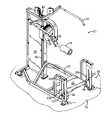
- FIG. 1is a perspective view of exercise apparatus for resistance training in accordance with the invention.
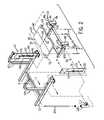
- FIG. 2is an exploded perspective view of a portion of FIG. 1 .
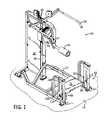
- FIG. 3is an enlarged perspective view of a portion of FIG. 1 .
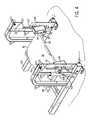
- FIG. 4is like FIG. 3 and shows an alternate position of the platform.
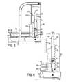
- FIG. 5is a side elevation view of the structure of FIG. 3 .
- FIG. 6is a sectional view taken along line 6 - 6 of FIG. 3 .
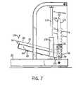
- FIG. 7is like FIG. 5 and illustrates operation of the platform during a height change.
- FIG. 8is like FIG. 7 and shows completion of a height adjustment to a new vertical elevation.
- FIG. 9is an enlarged view of a portion of FIG. 3 , and shows a further embodiment.
- FIG. 1shows exercise apparatus 20 for resistance training, including a frame 22 resting on a floor 24 and supporting a laterally extending platform 26 at a plurality of vertical elevations, to be described.
- Platform 26supports and locates a user for resistance training, e.g. a hip flexor or hip glute routine wherein the user extends one leg over pad 28 , while holding onto handlebar 30 and/or 32 , and swings leg/knee pad 28 in an arc to rotate pulley 34 to in turn lift one or more weights in weight stack 36 (partially hidden by shield plate 38 ) via pulley cable system 40 , all as is known.
- Platform 26supports and locates the user for such resistance training, e.g. supporting one leg and foot of the user, while the other leg is extended over and partially around pad 28 .
- Platform 26has distally opposite first and second sides 50 and 52 laterally spaced along a first lateral axis 54 .
- the platformhas distally opposite third and fourth sides 56 and 58 laterally spaced along a second lateral axis 60 .
- Lateral axes 54 and 60are normal to each other.
- An adjustment mechanism 62is provided for raising and lowering platform 26 to a plurality of vertical elevations.
- the adjustment mechanismboth: a) journals platform 26 to pivot about a pivot axis 64 parallel to first lateral axis 54 into and out of engagement with a detent lock 66 , to be described, such that platform 26 is locked in place at a given vertical elevation when pivoted into engagement with the detent lock, and the platform may move up and down when pivoted out of engagement with the detent lock; and b) linearly guides translational movement of platform 26 during the noted up and down movement of the platform and prevents side to side canting of the platform about second lateral axis 60 during the noted up and down movement of the platform and preventing misalignment of first and second sides 50 and 52 of the platform.
- Adjustment mechanism 62includes first and second stanchions 68 and 70 extending upwardly from frame 22 . Each stanchion has a respective track 72 and 74 extending upwardly and downwardly therealong, and a respective tooth rack 76 and 78 extending upwardly and downwardly therealong.
- Platform 26includes a floorboard 80 mounted by bolts 82 to a carriage 84 having first and second bearing blocks 86 and 88 pivotable about and translational along respective stanchions 68 and 70 . Tooth racks 76 , 78 provide the noted detent lock, to be further described.
- First bearing block 86has a horizontal first main shaft 90 , FIGS. 2 , 3 , translational along track 72 of stanchion 68 , FIGS. 5-8 , and moving upwardly and downwardly therealong during up and down movement of platform 26 .
- Second bearing block 88has a horizontal second main shaft 92 translational along track 74 of stanchion 70 and moving upwardly and downwardly therealong during up and down movement of platform 26 .
- Horizontal first and second main shafts 90 and 92are coaxial.
- Platform 26is pivoted between a first locked position, FIGS. 1 , 3 - 6 , 8 , and a second unlocked position, FIG. 7 , by swinging the noted third side 56 of platform 26 upwardly and downwardly, FIGS.
- First bearing block 86has a horizontal first auxiliary shaft 94 , FIGS. 2 , 3 , engaging a given first tooth 96 in tooth rack 76 of stanchion 68 in the noted first pivoted locked position of platform 26 to lock the platform at a given one of the noted vertical elevations corresponding to tooth 96 .
- Horizontal first auxiliary shaft 94disengages tooth rack 76 of stanchion 68 in the noted second pivoted unlocked position of platform 26 to, unlock the platform and permit upward and downward movement thereof, FIG. 7 .
- Second bearing block 88has a horizontal second auxiliary shaft 98 , FIGS.
- Horizontal first and second main shafts 90 and 92engage tracks 72 and 74 of first and second stanchions 68 and 70 , respectively, at each of the vertical elevations along the stanchions at respective vertically spaced teeth of the respective tooth racks, and during at least a portion of travel of the platform during the up and down movement thereof.
- Adjustment mechanism 66further includes first and second guide rods 102 and 104 , FIGS. 1-3 , extending upwardly from frame 22 adjacent first and second stanchions 68 and 70 , respectively.
- the adjustment mechanismfurther includes first and second linear bearing assemblies 106 and 108 slidable upwardly and downwardly along respective first and second guide rods 102 and 104 and operatively connected to respective first and second bearing blocks 86 and 88 to guide translational up and down movement of first and second bearing blocks 86 and 88 and prevent canting of platform 26 about the noted second lateral axis 60 .
- First and second linear bearing assemblies 106 and 108have respective first and second bearing sub-blocks 110 and 112 laterally adjacent respective first and second stanchions 68 and 70 .
- Horizontal first main shaft 90has a first end 114 mounted to first bearing block 86 , and has a second end 116 mounted to first bearing sub-block 110 .
- Horizontal second main shaft 92has a first end 118 mounted to second bearing block 88 , and has a second end 120 mounted to second bearing sub-block 112 .
- First stanchion 68is disposed laterally between first bearing block 86 and first bearing sub-block 110 .
- Second stanchion 70is disposed laterally between second bearing block 88 and second bearing sub-block 112 .
- Guide rods 102 and 104extend upwardly to upper ends which are mounted to support arms 103 and 105 of the frame to rigidly locate and anchor guide rods 102 and 104 .
- Support arms 103 and 105extend upwardly from the frame and then curve laterally and are bolted to respective stanchions 68 and 70 at respective bolts 107 and 109 .
- First stanchion 68has a first slot 122 formed laterally therethrough, which slot is elongated upwardly and downwardly along first stanchion 68 and has opposing elongated inner sides 124 and 126 facing each other across such slot.
- Inner side 124provides the noted track 72 of first stanchion 68
- inner side 126provides the noted tooth rack 76 of first stanchion 68 .
- Horizontal first main shaft 90extends laterally through first slot 122 .
- Second stanchion 70has a second slot 128 formed laterally therethrough, which slot is elongated upwardly and downwardly along second stanchion 70 and has opposing elongated inner sides 130 and 132 facing each other across slot 128 .
- Second slot 128provides the noted track 74 of second stanchion 70
- inner side 132 of second slot 128provides the noted tooth rack 78 of second stanchion 70
- Horizontal second main shaft 92extends laterally through second slot 128 .
- platform 26is a stand-upon platform supporting the feet of the user, though other types of support platforms may be used.
- Platform 26is a cantilever having a root end at fourth side 58 , and a free end at third side 56 .
- the usergrips the platform at third and fourth sides 56 and 58 , and then tilts third side 56 upwardly, as shown at arrow 134 in FIG. 7 , to move auxiliary shafts 94 and 98 out of engagement with respective teeth, as shown at arrow 136 , and then the platform is translated upwardly as guided by linear bearing assemblies 106 and 108 along guide rods 102 and 104 , as shown at arrow 138 in FIG. 8 , whereafter third side 56 of the platform is tilted downwardly to in turn move auxiliary shafts 94 and 98 into engagement with respective teeth of respective tooth racks, as shown at arrow 140 in FIG. 8 .
- horizontal auxiliary shaft 98 of FIG. 3includes a cam follower 142 journaled thereto.
- Horizontal first auxiliary shaft 98engages tooth rack 78 and its teeth of stanchion 70 at cam follower 142 .
- Horizontal auxiliary shaft 94also includes a cam follower as shown in dashed line at 144 in FIG. 3 , journaled thereto, and horizontal auxiliary shaft 94 engages tooth rack 76 and its teeth of stanchion 68 at cam follower 144 .
- the cam followersmay be desirable to reduce the chance of a “false lock” and to make adjustment easier. False lock could possibly occur if a shaft such as 98 catches on the point of the tooth increment, e.g.
- Tooth racks 78 and 76are modified to fit the diameter of the respective cam follower 142 and 144 which is larger than the diameter of the respective shaft 98 and 94 .
- cam followers 142 and 144can come into contact with inner sides 130 and 124 of the respective slots and roll therealong, resulting in easier raising and lowering of the platform.
- the teeth of tooth racks 78 and 76may thus be engaged directly by respective shafts 98 and 94 as in FIGS. 1-8 , or may be engaged through respective cam followers 142 and 144 as in FIG. 9 .
Landscapes
- Health & Medical Sciences (AREA)
- Orthopedic Medicine & Surgery (AREA)
- General Health & Medical Sciences (AREA)
- Physical Education & Sports Medicine (AREA)
- Life Sciences & Earth Sciences (AREA)
- Biophysics (AREA)
- Rehabilitation Tools (AREA)
Abstract
Description
Claims (5)
Priority Applications (1)
| Application Number | Priority Date | Filing Date | Title |
|---|---|---|---|
| US11/677,628US7476186B1 (en) | 2007-02-22 | 2007-02-22 | Exercise apparatus with platform adjustment mechanism |
Applications Claiming Priority (1)
| Application Number | Priority Date | Filing Date | Title |
|---|---|---|---|
| US11/677,628US7476186B1 (en) | 2007-02-22 | 2007-02-22 | Exercise apparatus with platform adjustment mechanism |
Publications (1)
| Publication Number | Publication Date |
|---|---|
| US7476186B1true US7476186B1 (en) | 2009-01-13 |
Family
ID=40223849
Family Applications (1)
| Application Number | Title | Priority Date | Filing Date |
|---|---|---|---|
| US11/677,628Expired - Fee RelatedUS7476186B1 (en) | 2007-02-22 | 2007-02-22 | Exercise apparatus with platform adjustment mechanism |
Country Status (1)
| Country | Link |
|---|---|
| US (1) | US7476186B1 (en) |
Cited By (18)
| Publication number | Priority date | Publication date | Assignee | Title |
|---|---|---|---|---|
| US20100248909A1 (en)* | 2009-03-30 | 2010-09-30 | Brad Thorpe | Isometric exercise apparatus and storage rack therefor |
| US20110098160A1 (en)* | 2008-08-21 | 2011-04-28 | Gil Reyes | Hip flexor |
| US20110204760A1 (en)* | 2010-01-11 | 2011-08-25 | Cannon Equipment Company | Cabinet with adjustable shelf |
| USD673626S1 (en)* | 2011-07-19 | 2013-01-01 | Icon Health & Fitness, Inc. | Exercise device |
| US9109804B2 (en) | 2013-02-25 | 2015-08-18 | General Electric Company | Appliance with vertically adjustable rack |
| US10188890B2 (en) | 2013-12-26 | 2019-01-29 | Icon Health & Fitness, Inc. | Magnetic resistance mechanism in a cable machine |
| US10252109B2 (en) | 2016-05-13 | 2019-04-09 | Icon Health & Fitness, Inc. | Weight platform treadmill |
| US10279212B2 (en) | 2013-03-14 | 2019-05-07 | Icon Health & Fitness, Inc. | Strength training apparatus with flywheel and related methods |
| US10293211B2 (en) | 2016-03-18 | 2019-05-21 | Icon Health & Fitness, Inc. | Coordinated weight selection |
| US10426989B2 (en) | 2014-06-09 | 2019-10-01 | Icon Health & Fitness, Inc. | Cable system incorporated into a treadmill |
| US10441840B2 (en) | 2016-03-18 | 2019-10-15 | Icon Health & Fitness, Inc. | Collapsible strength exercise machine |
| US10449416B2 (en) | 2015-08-26 | 2019-10-22 | Icon Health & Fitness, Inc. | Strength exercise mechanisms |
| US20200101348A1 (en)* | 2018-09-27 | 2020-04-02 | Brunswick Corporation | Exercise Machines for Leg Strengthening |
| US10661114B2 (en) | 2016-11-01 | 2020-05-26 | Icon Health & Fitness, Inc. | Body weight lift mechanism on treadmill |
| CN112237717A (en)* | 2020-11-06 | 2021-01-19 | 青岛英派斯健康科技股份有限公司 | Rotary training machine and chain slewing mechanism |
| US10940360B2 (en) | 2015-08-26 | 2021-03-09 | Icon Health & Fitness, Inc. | Strength exercise mechanisms |
| US11660499B2 (en)* | 2016-12-05 | 2023-05-30 | Eun Bee Kim | Upper leg and hip exercise method and device to preserve knee and ankle joint while exercising |
| US11660498B2 (en)* | 2016-12-05 | 2023-05-30 | Eun Bee Kim | Upper leg and hip exercise method and device to preserve knee and ankle joint while exercising |
Citations (51)
| Publication number | Priority date | Publication date | Assignee | Title |
|---|---|---|---|---|
| US300887A (en)* | 1884-06-24 | Adjustable trestle | ||
| US324602A (en)* | 1885-08-18 | Book-rest | ||
| US730894A (en)* | 1903-03-19 | 1903-06-16 | Mary Ellen Fairbanks | Tailor's measure. |
| US775496A (en)* | 1904-03-21 | 1904-11-22 | Library Bureau | Library-shelf. |
| US806485A (en)* | 1905-07-13 | 1905-12-05 | Clara E Parker | Folding and adjustable table. |
| US1063766A (en)* | 1912-06-25 | 1913-06-03 | Lyda Becker | Folding skirt-marker. |
| US2468856A (en)* | 1944-10-09 | 1949-05-03 | John A Alexander | Combined table and desk for children |
| US3128074A (en)* | 1962-10-05 | 1964-04-07 | Bro Dart Ind Inc | Metal shel ving bracket |
| US3638584A (en)* | 1969-05-21 | 1972-02-01 | American Hospital Supply Corp | Drafting table construction |
| US3640527A (en)* | 1969-07-25 | 1972-02-08 | Richard I Proctor | Weight resistant chest exercising device |
| US4026222A (en)* | 1976-04-12 | 1977-05-31 | Christine E. Mueller | Adjustable load-supporting structure |
| US4231301A (en)* | 1977-08-29 | 1980-11-04 | Barrineau Iii Wade H | Adjustable shelf assembly |
| US4292902A (en)* | 1975-11-03 | 1981-10-06 | Barrineau Wade H | Shelf system |
| US4383486A (en)* | 1980-07-28 | 1983-05-17 | Rol-Fol Table, Inc. | Desk for handicapped persons |
| US4470596A (en)* | 1982-12-29 | 1984-09-11 | Ron Desiderio | Exercise weight-lifting apparatus and improved carriage for same |
| US4565368A (en)* | 1983-08-11 | 1986-01-21 | Gunderson Clinic | Isokinetic exercise and monitoring machine |
| US4627616A (en)* | 1985-07-09 | 1986-12-09 | Brad Kauffman | Exercise apparatus |
| US4702108A (en)* | 1985-06-24 | 1987-10-27 | Regents Of The Univ. Of Minnesota | Method and apparatus for measuring the isometric muscle strength of multiple muscle groups in the human body |
| US4711448A (en)* | 1985-04-11 | 1987-12-08 | Minkow Roger E | Lower body exercising and weight training device |
| US4795149A (en)* | 1988-01-13 | 1989-01-03 | Pearson Bruce E | Lunge training machine for body builders |
| US5039054A (en)* | 1989-12-29 | 1991-08-13 | I Pai | Safe height-adjusting device |
| US5050868A (en)* | 1990-03-16 | 1991-09-24 | Criterion Bodybuilding Equipment, Inc. | Leg training machine for body builders |
| US5308304A (en)* | 1992-07-22 | 1994-05-03 | Pacific Fitness Corporation | Multi-hip exerciser |
| US5365860A (en)* | 1992-10-08 | 1994-11-22 | Billington Welding & Manufacturing, Inc. | Manually-adjustable cantilevered work station platform |
| US5410971A (en)* | 1992-10-15 | 1995-05-02 | Jeff Industries, Inc. | Adjustable work station for the handicapped |
| US5483902A (en)* | 1993-09-14 | 1996-01-16 | Grosch; Peter T. | Adjustable work surface for computer stations |
| US5492518A (en)* | 1994-09-06 | 1996-02-20 | Measom; S. Ty | Exercise apparatus |
| US5554085A (en)* | 1994-02-03 | 1996-09-10 | Icon Health & Fitness, Inc. | Weight-training machine |
| US5695078A (en)* | 1995-03-30 | 1997-12-09 | Otema; Martin | Adjustable standard system |
| US5711749A (en)* | 1995-10-06 | 1998-01-27 | Aerobic Funding One, Llc | Trunk strengthening cardiovascular exercise apparatus |
| US5718406A (en)* | 1996-01-11 | 1998-02-17 | Long; Dennis L. | Counterbalance apparatus |
| US5735222A (en)* | 1994-02-18 | 1998-04-07 | Webb; Sharon L. | Vertically adjustable detachable keyboard tray |
| US5813951A (en)* | 1995-10-30 | 1998-09-29 | Einsig; Harold Joseph | Total body exercising and rehabilitation weight lifting machine and method |
| US6036624A (en)* | 1997-01-24 | 2000-03-14 | Technogym S.R.L. | Physical training apparatus, particularly for the training of the shoulder rotators |
| US6205934B1 (en)* | 1998-12-11 | 2001-03-27 | Versatile Products Llc | Support and related shelf |
| US6283898B1 (en)* | 1997-08-04 | 2001-09-04 | Richard Zachary Polidi | Mechanical weightlifting machine |
| US6319177B1 (en)* | 1999-08-30 | 2001-11-20 | Dan Levine | Portable and pivotal stationary exercise system |
| US6378446B1 (en)* | 1999-12-30 | 2002-04-30 | Dennis L. Long | Counterbalance apparatus |
| US6402633B1 (en)* | 2001-05-10 | 2002-06-11 | Bob Hsiung | Golf swing training and exercising device |
| US6540093B1 (en)* | 2001-11-21 | 2003-04-01 | Cindy A. Shumway | Window shelf system |
| US6584916B1 (en)* | 1998-12-11 | 2003-07-01 | Versatile Products Llc | Support and related shelf |
| US6623409B1 (en)* | 2000-10-17 | 2003-09-23 | Kevin G. Abelbeck | Automatic locking exercise device and method |
| US6675725B2 (en)* | 1998-12-11 | 2004-01-13 | Versatile Products Llc | Shelf and shelf support |
| US20050066861A1 (en)* | 2003-09-29 | 2005-03-31 | The Brewer Company, Llc | Lifting column for a medical examination table |
| US6962116B2 (en)* | 2003-01-31 | 2005-11-08 | Gemtron Corporation | Refrigerator compartment housing vertically adjustable shelves |
| US6966267B2 (en)* | 2003-01-31 | 2005-11-22 | Gemtron Corporation | Refrigerator compartment housing vertically adjustable shelves |
| US7093691B1 (en)* | 2005-04-04 | 2006-08-22 | Barry Vaughan | Portable scissor-lift-assembly |
| US20060252609A1 (en)* | 2005-05-05 | 2006-11-09 | The Brinkmann Corporation | Exercise device with a safety lock |
| US20070042876A1 (en)* | 2005-08-19 | 2007-02-22 | Recreation Supply, Inc. | Weight lifting power cage with slave rack |
| US20080017776A1 (en)* | 2006-07-24 | 2008-01-24 | Yun-Fei Wang | Desk for reading and writing |
| US7337730B2 (en)* | 2003-01-31 | 2008-03-04 | Gemtron Corporation | Vertically adjustable shelves and refrigerator compartment housing the same |
- 2007
- 2007-02-22USUS11/677,628patent/US7476186B1/ennot_activeExpired - Fee Related
Patent Citations (54)
| Publication number | Priority date | Publication date | Assignee | Title |
|---|---|---|---|---|
| US300887A (en)* | 1884-06-24 | Adjustable trestle | ||
| US324602A (en)* | 1885-08-18 | Book-rest | ||
| US730894A (en)* | 1903-03-19 | 1903-06-16 | Mary Ellen Fairbanks | Tailor's measure. |
| US775496A (en)* | 1904-03-21 | 1904-11-22 | Library Bureau | Library-shelf. |
| US806485A (en)* | 1905-07-13 | 1905-12-05 | Clara E Parker | Folding and adjustable table. |
| US1063766A (en)* | 1912-06-25 | 1913-06-03 | Lyda Becker | Folding skirt-marker. |
| US2468856A (en)* | 1944-10-09 | 1949-05-03 | John A Alexander | Combined table and desk for children |
| US3128074A (en)* | 1962-10-05 | 1964-04-07 | Bro Dart Ind Inc | Metal shel ving bracket |
| US3638584A (en)* | 1969-05-21 | 1972-02-01 | American Hospital Supply Corp | Drafting table construction |
| US3640527A (en)* | 1969-07-25 | 1972-02-08 | Richard I Proctor | Weight resistant chest exercising device |
| US4292902A (en)* | 1975-11-03 | 1981-10-06 | Barrineau Wade H | Shelf system |
| US4026222A (en)* | 1976-04-12 | 1977-05-31 | Christine E. Mueller | Adjustable load-supporting structure |
| US4231301A (en)* | 1977-08-29 | 1980-11-04 | Barrineau Iii Wade H | Adjustable shelf assembly |
| US4383486A (en)* | 1980-07-28 | 1983-05-17 | Rol-Fol Table, Inc. | Desk for handicapped persons |
| US4470596A (en)* | 1982-12-29 | 1984-09-11 | Ron Desiderio | Exercise weight-lifting apparatus and improved carriage for same |
| US4565368A (en)* | 1983-08-11 | 1986-01-21 | Gunderson Clinic | Isokinetic exercise and monitoring machine |
| US4711448A (en)* | 1985-04-11 | 1987-12-08 | Minkow Roger E | Lower body exercising and weight training device |
| US4702108A (en)* | 1985-06-24 | 1987-10-27 | Regents Of The Univ. Of Minnesota | Method and apparatus for measuring the isometric muscle strength of multiple muscle groups in the human body |
| US4627616A (en)* | 1985-07-09 | 1986-12-09 | Brad Kauffman | Exercise apparatus |
| US4795149A (en)* | 1988-01-13 | 1989-01-03 | Pearson Bruce E | Lunge training machine for body builders |
| US5039054A (en)* | 1989-12-29 | 1991-08-13 | I Pai | Safe height-adjusting device |
| US5050868A (en)* | 1990-03-16 | 1991-09-24 | Criterion Bodybuilding Equipment, Inc. | Leg training machine for body builders |
| US5308304A (en)* | 1992-07-22 | 1994-05-03 | Pacific Fitness Corporation | Multi-hip exerciser |
| US5354252A (en)* | 1992-07-22 | 1994-10-11 | Pacific Fitness Corporation | Multi-hip exerciser |
| US5468202A (en)* | 1992-07-22 | 1995-11-21 | Pacific Fitness Corporation | Multi-hip exerciser |
| US5365860A (en)* | 1992-10-08 | 1994-11-22 | Billington Welding & Manufacturing, Inc. | Manually-adjustable cantilevered work station platform |
| US5410971A (en)* | 1992-10-15 | 1995-05-02 | Jeff Industries, Inc. | Adjustable work station for the handicapped |
| US5483902A (en)* | 1993-09-14 | 1996-01-16 | Grosch; Peter T. | Adjustable work surface for computer stations |
| US5554085A (en)* | 1994-02-03 | 1996-09-10 | Icon Health & Fitness, Inc. | Weight-training machine |
| US5735222A (en)* | 1994-02-18 | 1998-04-07 | Webb; Sharon L. | Vertically adjustable detachable keyboard tray |
| US5492518A (en)* | 1994-09-06 | 1996-02-20 | Measom; S. Ty | Exercise apparatus |
| US5695078A (en)* | 1995-03-30 | 1997-12-09 | Otema; Martin | Adjustable standard system |
| US5711749A (en)* | 1995-10-06 | 1998-01-27 | Aerobic Funding One, Llc | Trunk strengthening cardiovascular exercise apparatus |
| US5813951A (en)* | 1995-10-30 | 1998-09-29 | Einsig; Harold Joseph | Total body exercising and rehabilitation weight lifting machine and method |
| US5718406A (en)* | 1996-01-11 | 1998-02-17 | Long; Dennis L. | Counterbalance apparatus |
| US6036624A (en)* | 1997-01-24 | 2000-03-14 | Technogym S.R.L. | Physical training apparatus, particularly for the training of the shoulder rotators |
| US6283898B1 (en)* | 1997-08-04 | 2001-09-04 | Richard Zachary Polidi | Mechanical weightlifting machine |
| US6205934B1 (en)* | 1998-12-11 | 2001-03-27 | Versatile Products Llc | Support and related shelf |
| US6584916B1 (en)* | 1998-12-11 | 2003-07-01 | Versatile Products Llc | Support and related shelf |
| US6675725B2 (en)* | 1998-12-11 | 2004-01-13 | Versatile Products Llc | Shelf and shelf support |
| US6319177B1 (en)* | 1999-08-30 | 2001-11-20 | Dan Levine | Portable and pivotal stationary exercise system |
| US6378446B1 (en)* | 1999-12-30 | 2002-04-30 | Dennis L. Long | Counterbalance apparatus |
| US6623409B1 (en)* | 2000-10-17 | 2003-09-23 | Kevin G. Abelbeck | Automatic locking exercise device and method |
| US6402633B1 (en)* | 2001-05-10 | 2002-06-11 | Bob Hsiung | Golf swing training and exercising device |
| US6540093B1 (en)* | 2001-11-21 | 2003-04-01 | Cindy A. Shumway | Window shelf system |
| US6962116B2 (en)* | 2003-01-31 | 2005-11-08 | Gemtron Corporation | Refrigerator compartment housing vertically adjustable shelves |
| US6966267B2 (en)* | 2003-01-31 | 2005-11-22 | Gemtron Corporation | Refrigerator compartment housing vertically adjustable shelves |
| US20050274299A1 (en)* | 2003-01-31 | 2005-12-15 | Craig Bienick | Refrigerator compartment housing vertically adjustable shelves |
| US7337730B2 (en)* | 2003-01-31 | 2008-03-04 | Gemtron Corporation | Vertically adjustable shelves and refrigerator compartment housing the same |
| US20050066861A1 (en)* | 2003-09-29 | 2005-03-31 | The Brewer Company, Llc | Lifting column for a medical examination table |
| US7093691B1 (en)* | 2005-04-04 | 2006-08-22 | Barry Vaughan | Portable scissor-lift-assembly |
| US20060252609A1 (en)* | 2005-05-05 | 2006-11-09 | The Brinkmann Corporation | Exercise device with a safety lock |
| US20070042876A1 (en)* | 2005-08-19 | 2007-02-22 | Recreation Supply, Inc. | Weight lifting power cage with slave rack |
| US20080017776A1 (en)* | 2006-07-24 | 2008-01-24 | Yun-Fei Wang | Desk for reading and writing |
Cited By (27)
| Publication number | Priority date | Publication date | Assignee | Title |
|---|---|---|---|---|
| US20110098160A1 (en)* | 2008-08-21 | 2011-04-28 | Gil Reyes | Hip flexor |
| US8376917B2 (en)* | 2009-03-30 | 2013-02-19 | Brad Thorpe | Isometric exercise apparatus and storage rack therefor |
| US9592416B2 (en) | 2009-03-30 | 2017-03-14 | Isologex Corporation | Isometric exercise apparatus and storage rack therefor |
| US8029423B2 (en)* | 2009-03-30 | 2011-10-04 | Brad Thorpe | Isometric exercise apparatus and storage rack therefor |
| US20110319232A1 (en)* | 2009-03-30 | 2011-12-29 | Brad Thorpe | Isometric exercise apparatus and storage rack therefor |
| US10391350B2 (en) | 2009-03-30 | 2019-08-27 | Isologex Corporation | Isometric exercise apparatus and storage rack therefor |
| US8758203B2 (en) | 2009-03-30 | 2014-06-24 | Brad Thorpe | Isometric exercise apparatus and storage rack therefor |
| US20100248909A1 (en)* | 2009-03-30 | 2010-09-30 | Brad Thorpe | Isometric exercise apparatus and storage rack therefor |
| US20110204760A1 (en)* | 2010-01-11 | 2011-08-25 | Cannon Equipment Company | Cabinet with adjustable shelf |
| US8764031B2 (en)* | 2010-01-11 | 2014-07-01 | Cannon Equipment Company | Cabinet with adjustable shelf |
| USD673626S1 (en)* | 2011-07-19 | 2013-01-01 | Icon Health & Fitness, Inc. | Exercise device |
| US9109804B2 (en) | 2013-02-25 | 2015-08-18 | General Electric Company | Appliance with vertically adjustable rack |
| US10279212B2 (en) | 2013-03-14 | 2019-05-07 | Icon Health & Fitness, Inc. | Strength training apparatus with flywheel and related methods |
| US10188890B2 (en) | 2013-12-26 | 2019-01-29 | Icon Health & Fitness, Inc. | Magnetic resistance mechanism in a cable machine |
| US10426989B2 (en) | 2014-06-09 | 2019-10-01 | Icon Health & Fitness, Inc. | Cable system incorporated into a treadmill |
| US10449416B2 (en) | 2015-08-26 | 2019-10-22 | Icon Health & Fitness, Inc. | Strength exercise mechanisms |
| US10940360B2 (en) | 2015-08-26 | 2021-03-09 | Icon Health & Fitness, Inc. | Strength exercise mechanisms |
| US10293211B2 (en) | 2016-03-18 | 2019-05-21 | Icon Health & Fitness, Inc. | Coordinated weight selection |
| US10441840B2 (en) | 2016-03-18 | 2019-10-15 | Icon Health & Fitness, Inc. | Collapsible strength exercise machine |
| US10252109B2 (en) | 2016-05-13 | 2019-04-09 | Icon Health & Fitness, Inc. | Weight platform treadmill |
| US10661114B2 (en) | 2016-11-01 | 2020-05-26 | Icon Health & Fitness, Inc. | Body weight lift mechanism on treadmill |
| US11660499B2 (en)* | 2016-12-05 | 2023-05-30 | Eun Bee Kim | Upper leg and hip exercise method and device to preserve knee and ankle joint while exercising |
| US11660498B2 (en)* | 2016-12-05 | 2023-05-30 | Eun Bee Kim | Upper leg and hip exercise method and device to preserve knee and ankle joint while exercising |
| US20200101348A1 (en)* | 2018-09-27 | 2020-04-02 | Brunswick Corporation | Exercise Machines for Leg Strengthening |
| CN110947159A (en)* | 2018-09-27 | 2020-04-03 | 生命健康有限责任公司 | exercise machine for leg strengthening |
| US10786705B2 (en)* | 2018-09-27 | 2020-09-29 | Life Fitness, Llc | Exercise machines for leg strengthening |
| CN112237717A (en)* | 2020-11-06 | 2021-01-19 | 青岛英派斯健康科技股份有限公司 | Rotary training machine and chain slewing mechanism |
Similar Documents
| Publication | Publication Date | Title |
|---|---|---|
| US7476186B1 (en) | Exercise apparatus with platform adjustment mechanism | |
| US11826604B2 (en) | Tilting exercise machine | |
| US9517375B2 (en) | Exercise machine support system | |
| US20130331239A1 (en) | Weight Lifting Machines and Methods | |
| AU660684B2 (en) | Guidance system for an upper body exercise apparatus | |
| CN104936660B (en) | Bench press combining whole body safety rod and sliding rod holding arm | |
| US7927263B1 (en) | Exercise equipment with dock-and-lock and spotter platform | |
| EP1945320B1 (en) | Apparatus for exercising multiple body parts | |
| EP0416783A2 (en) | Compact multi-function weight training exerciser | |
| US20120066831A1 (en) | Patient transfer apparatus | |
| EP2217192A4 (en) | Height adjustable support assembly | |
| CA3112238C (en) | Glute press exercise machine | |
| RU2403936C2 (en) | Training simulator for muscle-strengthening exercises and rehabilitation | |
| KR20130126413A (en) | Patient transfer apparatus using side safety rails | |
| KR102150833B1 (en) | Lifting device designed to lift poultry legs that are transported continuously hanging | |
| US12201865B2 (en) | Exercise machine support system | |
| US6217484B1 (en) | Rehabilitation apparatus | |
| KR20150078399A (en) | Seating-Type Supporting Unit And Seating-Type Apparatus For Training Walk Using The Same | |
| RU2415661C2 (en) | Transport trolley for surgical table surface for patient placement | |
| CN110236823B (en) | A manual and automatic wheelchair bed | |
| US20240293696A1 (en) | Exercise machines for weight training | |
| CN112774084B (en) | Exercise equipment | |
| CN108420653A (en) | Concealed guardrail bed apparatus | |
| WO1998020829A1 (en) | A suspension system, and a height-adjustable bed incorporating the suspension system | |
| CN120078593B (en) | A civilian emergency transport device |
Legal Events
| Date | Code | Title | Description |
|---|---|---|---|
| AS | Assignment | Owner name:BRUNSWICK CORPORATION, ILLINOIS Free format text:ASSIGNMENT OF ASSIGNORS INTEREST;ASSIGNOR:STEFFEE, CLAY J.;REEL/FRAME:019016/0156 Effective date:20070220 | |
| STCF | Information on status: patent grant | Free format text:PATENTED CASE | |
| AS | Assignment | Owner name:JPMORGAN CHASE BANK, N.A., TEXAS Free format text:SECURITY AGREEMENT;ASSIGNORS:BRUNSWICK CORPORATION;TRITON BOAT COMPANY, L.P.;ATTWOOD CORPORATION;AND OTHERS;REEL/FRAME:022092/0365 Effective date:20081219 Owner name:JPMORGAN CHASE BANK, N.A.,TEXAS Free format text:SECURITY AGREEMENT;ASSIGNORS:BRUNSWICK CORPORATION;TRITON BOAT COMPANY, L.P.;ATTWOOD CORPORATION;AND OTHERS;REEL/FRAME:022092/0365 Effective date:20081219 | |
| AS | Assignment | Owner name:THE BANK OF NEW YORK MELLON TRUST COMPANY, N.A., I Free format text:SECURITY AGREEMENT;ASSIGNORS:BRUNSWICK CORPORATION;ATTWOOD CORPORATION;BOSTON WHALER, INC.;AND OTHERS;REEL/FRAME:023180/0493 Effective date:20090814 Owner name:THE BANK OF NEW YORK MELLON TRUST COMPANY, N.A.,IL Free format text:SECURITY AGREEMENT;ASSIGNORS:BRUNSWICK CORPORATION;ATTWOOD CORPORATION;BOSTON WHALER, INC.;AND OTHERS;REEL/FRAME:023180/0493 Effective date:20090814 | |
| FEPP | Fee payment procedure | Free format text:PAYOR NUMBER ASSIGNED (ORIGINAL EVENT CODE: ASPN); ENTITY STATUS OF PATENT OWNER: LARGE ENTITY | |
| AS | Assignment | Owner name:LAND 'N' SEA DISTRIBUTING, INC., FLORIDA Free format text:RELEASE BY SECURED PARTY;ASSIGNOR:JPMORGAN CHASE BANK, N.A., AS ADMINISTRATIVE AGENT;REEL/FRAME:026026/0001 Effective date:20110321 Owner name:BRUNSWICK COMMERICAL & GOVERNMENT PRODUCTS, INC., Free format text:RELEASE BY SECURED PARTY;ASSIGNOR:JPMORGAN CHASE BANK, N.A., AS ADMINISTRATIVE AGENT;REEL/FRAME:026026/0001 Effective date:20110321 Owner name:TRITON BOAT COMPANY, L.P., TENNESSEE Free format text:RELEASE BY SECURED PARTY;ASSIGNOR:JPMORGAN CHASE BANK, N.A., AS ADMINISTRATIVE AGENT;REEL/FRAME:026026/0001 Effective date:20110321 Owner name:BRUNSWICK LEISURE BOAT COMPANY, LLC, INDIANA Free format text:RELEASE BY SECURED PARTY;ASSIGNOR:JPMORGAN CHASE BANK, N.A., AS ADMINISTRATIVE AGENT;REEL/FRAME:026026/0001 Effective date:20110321 Owner name:BRUNSWICK BOWLING & BILLIARDS CORPORATION, ILLINOI Free format text:RELEASE BY SECURED PARTY;ASSIGNOR:JPMORGAN CHASE BANK, N.A., AS ADMINISTRATIVE AGENT;REEL/FRAME:026026/0001 Effective date:20110321 Owner name:ATTWOOD CORPORATION, MICHIGAN Free format text:RELEASE BY SECURED PARTY;ASSIGNOR:JPMORGAN CHASE BANK, N.A., AS ADMINISTRATIVE AGENT;REEL/FRAME:026026/0001 Effective date:20110321 Owner name:BRUNSWICK CORPORATION, ILLINOIS Free format text:RELEASE BY SECURED PARTY;ASSIGNOR:JPMORGAN CHASE BANK, N.A., AS ADMINISTRATIVE AGENT;REEL/FRAME:026026/0001 Effective date:20110321 Owner name:BRUNSWICK FAMILY BOAT CO. INC., WASHINGTON Free format text:RELEASE BY SECURED PARTY;ASSIGNOR:JPMORGAN CHASE BANK, N.A., AS ADMINISTRATIVE AGENT;REEL/FRAME:026026/0001 Effective date:20110321 Owner name:BOSTON WHALER, INC., FLORIDA Free format text:RELEASE BY SECURED PARTY;ASSIGNOR:JPMORGAN CHASE BANK, N.A., AS ADMINISTRATIVE AGENT;REEL/FRAME:026026/0001 Effective date:20110321 Owner name:LUND BOAT COMPANY, MINNESOTA Free format text:RELEASE BY SECURED PARTY;ASSIGNOR:JPMORGAN CHASE BANK, N.A., AS ADMINISTRATIVE AGENT;REEL/FRAME:026026/0001 Effective date:20110321 | |
| AS | Assignment | Owner name:JPMORGAN CHASE BANK, N.A., AS ADMINISTRATIVE AGENT Free format text:SECURITY AGREEMENT;ASSIGNORS:BRUNSWICK CORPORATION;ATTWOOD CORPORATION;BOSTON WHALER, INC.;AND OTHERS;REEL/FRAME:026072/0239 Effective date:20110321 | |
| FPAY | Fee payment | Year of fee payment:4 | |
| AS | Assignment | Owner name:BRUNSWICK CORPORATION, ILLINOIS Free format text:RELEASE BY SECURED PARTY;ASSIGNOR:THE BANK OF NEW YORK MELLON;REEL/FRAME:031973/0242 Effective date:20130717 | |
| AS | Assignment | Owner name:LAND 'N' SEA DISTRIBUTING, INC., ILLINOIS Free format text:RELEASE BY SECURED PARTY;ASSIGNOR:JPMORGAN CHASE BANK, N.A.;REEL/FRAME:034794/0300 Effective date:20141226 Owner name:ATTWOOD CORPORATION, ILLINOIS Free format text:RELEASE BY SECURED PARTY;ASSIGNOR:JPMORGAN CHASE BANK, N.A.;REEL/FRAME:034794/0300 Effective date:20141226 Owner name:BOSTON WHALER, INC., ILLINOIS Free format text:RELEASE BY SECURED PARTY;ASSIGNOR:JPMORGAN CHASE BANK, N.A.;REEL/FRAME:034794/0300 Effective date:20141226 Owner name:BRUNSWICK FAMILY BOAT CO. INC., ILLINOIS Free format text:RELEASE BY SECURED PARTY;ASSIGNOR:JPMORGAN CHASE BANK, N.A.;REEL/FRAME:034794/0300 Effective date:20141226 Owner name:BRUNSWICK LEISURE BOAT COMPANY, LLC, ILLINOIS Free format text:RELEASE BY SECURED PARTY;ASSIGNOR:JPMORGAN CHASE BANK, N.A.;REEL/FRAME:034794/0300 Effective date:20141226 Owner name:BRUNSWICK BOWLING & BILLIARDS CORPORATION, ILLINOI Free format text:RELEASE BY SECURED PARTY;ASSIGNOR:JPMORGAN CHASE BANK, N.A.;REEL/FRAME:034794/0300 Effective date:20141226 Owner name:BRUNSWICK CORPORATION, ILLINOIS Free format text:RELEASE BY SECURED PARTY;ASSIGNOR:JPMORGAN CHASE BANK, N.A.;REEL/FRAME:034794/0300 Effective date:20141226 Owner name:LUND BOAT COMPANY, ILLINOIS Free format text:RELEASE BY SECURED PARTY;ASSIGNOR:JPMORGAN CHASE BANK, N.A.;REEL/FRAME:034794/0300 Effective date:20141226 Owner name:BRUNSWICK COMMERCIAL & GOVERNMENT PRODUCTS, INC., Free format text:RELEASE BY SECURED PARTY;ASSIGNOR:JPMORGAN CHASE BANK, N.A.;REEL/FRAME:034794/0300 Effective date:20141226 | |
| FPAY | Fee payment | Year of fee payment:8 | |
| AS | Assignment | Owner name:LIFE FITNESS, LLC, ILLINOIS Free format text:ASSIGNMENT OF ASSIGNORS INTEREST;ASSIGNOR:BRUNSWICK CORPORATION;REEL/FRAME:049585/0893 Effective date:20190624 | |
| AS | Assignment | Owner name:PNC BANK, NATIONAL ASSOCIATION, UNITED STATES Free format text:SECURITY AGREEMENT;ASSIGNOR:LIFE FITNESS, LLC;REEL/FRAME:049629/0124 Effective date:20190627 | |
| FEPP | Fee payment procedure | Free format text:MAINTENANCE FEE REMINDER MAILED (ORIGINAL EVENT CODE: REM.); ENTITY STATUS OF PATENT OWNER: LARGE ENTITY | |
| LAPS | Lapse for failure to pay maintenance fees | Free format text:PATENT EXPIRED FOR FAILURE TO PAY MAINTENANCE FEES (ORIGINAL EVENT CODE: EXP.); ENTITY STATUS OF PATENT OWNER: LARGE ENTITY | |
| STCH | Information on status: patent discontinuation | Free format text:PATENT EXPIRED DUE TO NONPAYMENT OF MAINTENANCE FEES UNDER 37 CFR 1.362 | |
| FP | Lapsed due to failure to pay maintenance fee | Effective date:20210113 |