US7475831B2 - Modified high efficiency kinetic spray nozzle - Google Patents
Modified high efficiency kinetic spray nozzleDownload PDFInfo
- Publication number
- US7475831B2 US7475831B2US10/763,824US76382404AUS7475831B2US 7475831 B2US7475831 B2US 7475831B2US 76382404 AUS76382404 AUS 76382404AUS 7475831 B2US7475831 B2US 7475831B2
- Authority
- US
- United States
- Prior art keywords
- nozzle
- expansion rate
- throat
- diverging region
- particles
- Prior art date
- Legal status (The legal status is an assumption and is not a legal conclusion. Google has not performed a legal analysis and makes no representation as to the accuracy of the status listed.)
- Active, expires
Links
Images


Classifications
- B—PERFORMING OPERATIONS; TRANSPORTING
- B05—SPRAYING OR ATOMISING IN GENERAL; APPLYING FLUENT MATERIALS TO SURFACES, IN GENERAL
- B05B—SPRAYING APPARATUS; ATOMISING APPARATUS; NOZZLES
- B05B7/00—Spraying apparatus for discharge of liquids or other fluent materials from two or more sources, e.g. of liquid and air, of powder and gas
- B05B7/14—Spraying apparatus for discharge of liquids or other fluent materials from two or more sources, e.g. of liquid and air, of powder and gas designed for spraying particulate materials
- B05B7/1481—Spray pistols or apparatus for discharging particulate material
- B05B7/1486—Spray pistols or apparatus for discharging particulate material for spraying particulate material in dry state
- C—CHEMISTRY; METALLURGY
- C23—COATING METALLIC MATERIAL; COATING MATERIAL WITH METALLIC MATERIAL; CHEMICAL SURFACE TREATMENT; DIFFUSION TREATMENT OF METALLIC MATERIAL; COATING BY VACUUM EVAPORATION, BY SPUTTERING, BY ION IMPLANTATION OR BY CHEMICAL VAPOUR DEPOSITION, IN GENERAL; INHIBITING CORROSION OF METALLIC MATERIAL OR INCRUSTATION IN GENERAL
- C23C—COATING METALLIC MATERIAL; COATING MATERIAL WITH METALLIC MATERIAL; SURFACE TREATMENT OF METALLIC MATERIAL BY DIFFUSION INTO THE SURFACE, BY CHEMICAL CONVERSION OR SUBSTITUTION; COATING BY VACUUM EVAPORATION, BY SPUTTERING, BY ION IMPLANTATION OR BY CHEMICAL VAPOUR DEPOSITION, IN GENERAL
- C23C24/00—Coating starting from inorganic powder
- C23C24/02—Coating starting from inorganic powder by application of pressure only
- C23C24/04—Impact or kinetic deposition of particles
Definitions
- the present inventionis directed toward a design for a supersonic nozzle, and more particularly, toward a nozzle for a kinetic spray system.
- the present inventioncomprises an improvement to the kinetic spray process as generally described in U.S. Pat. Nos. 6,139,913, 6,283,386 and the articles by Van Steenkiste, et al. entitled “Kinetic Spray Coatings” published in Surface and Coatings Technology Volume III, Pages 62-72, Jan. 10, 1999, and “Aluminum coatings via kinetic spray with relatively large powder particles”, published in Surface and Coatings Technology 154, pp. 237-252, 2002, all of which are herein incorporated by reference.
- the articlesdescribe coatings being produced by entraining metal powders in an accelerated gas stream, through a converging-diverging de Laval type nozzle and projecting them against a target substrate.
- the particlesare accelerated in the high velocity gas stream by the drag effect.
- the gas usedcan be any of a variety of gases including air, nitrogen or helium. It was found that the particles that formed the coating did not melt or thermally soften prior to impingement onto the substrate. It is theorized that the particles adhere to the substrate when their kinetic energy is converted to a sufficient level of thermal and mechanical deformation. Thus, it is believed that the particle velocity must exceed a critical velocity to permit it to adhere when it strikes the substrate. It was found that the deposition efficiency of a given particle mixture was increased as the main gas temperature was increased.
- Increasing the main gas temperaturedecreases its density and thus increases its velocity and increases its pressure.
- the velocityvaries approximately as the square root of the main gas temperature.
- the actual mechanism of bonding of the particles to the substrate surfaceis not fully known at this time.
- the critical velocityis dependent on the material of the particle and of the substrate.
- the present inventionis a supersonic kinetic spray nozzle comprising: a converging region and a diverging region separated by a throat; at least a portion of the diverging region adjacent the throat having a cross-sectional expansion rate of at least 1.0 millimeters squared per millimeter. This expansion rate varies linearly with the variation in the cross-sectional area of the throat. The rate of at least 1.0 millimeters squared per millimeter is favored for a throat cross-sectional area of 9.08 millimeters squared.
- the present inventionis a kinetic spray system comprising: a supersonic nozzle having a converging region and a diverging region separated by a throat; at least a portion of the diverging region adjacent the throat having a cross-sectional expansion rate of at least 1.0 millimeters squared per millimeter; at least one powder injector connected to the nozzle with one of a low pressure or a high pressure powder feeder connected to said injector; and a high pressure source of a heated main gas connected to the nozzle.
- the present inventionis a method of applying a material via a kinetic spray process comprising the steps of: providing particles of a material to be sprayed; providing a supersonic nozzle having a throat located between a converging region and a diverging region at least a portion of said diverging region adjacent said throat having a cross-sectional expansion rate of at least 1.0 millimeters squared per millimeter; directing a flow of a gas through the nozzle, the gas having a temperature insufficient to cause melting of the particles in the nozzle; and entraining the particles in the flow of the gas and accelerating the particles to a velocity sufficient to result in adherence of the particles on a substrate positioned opposite the nozzle.
- FIG. 1is a general schematic layout illustrating a kinetic spray system for performing the method of the present invention
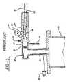
- FIG. 2is an enlarged cross-sectional view of a prior art kinetic spray nozzle used with a high pressure powder feeder in a kinetic spray system;
- FIG. 3is an enlarged cross-sectional view of a prior art kinetic spray nozzle used with a low pressure powder feeder in a kinetic spray system
- FIG. 4is an enlarged cross-sectional view of a kinetic spray nozzle of the present invention used with a high pressure powder feeder in the kinetic spray system;
- FIG. 5is an enlarged cross-sectional view of a kinetic spray nozzle of the present invention used with a low pressure powder feeder in the kinetic spray system;
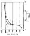
- FIG. 6is a graph showing the gas velocity of a gas through a prior art nozzle and nozzles designed according to the present invention as a function of the distance from the converging end of the nozzle;
- FIG. 7is a graph showing the cross-sectional area of nozzles normalized to the cross-sectional area of the throat as a function of the distance from the converging end of the nozzle.
- System 10includes an enclosure 12 in which a support table 14 or other support means is located.
- a mounting panel 16 fixed to the table 14supports a work holder 18 capable of movement in three dimensions and able to support a suitable workpiece formed of a substrate to be coated.
- the work holder 18is preferably designed to move a substrate relative to a nozzle 34 of the system 10 , thereby controlling where the powder material is deposited on the substrate.
- the work holder 18is capable of feeding a substrate past the nozzle 34 at traverse rates of up to 50 inches per second.
- the enclosure 12includes surrounding walls having at least one air inlet, not shown, and an air outlet 20 connected by a suitable exhaust conduit 22 to a dust collector, not shown.
- the dust collectorcontinually draws air from the enclosure 12 and collects any dust or particles contained in the exhaust air for subsequent disposal.
- the spray system 10further includes an gas compressor 24 capable of supplying gas pressure up to 3.4 MPa (500 pounds per square inch) to a high pressure gas ballast tank 26 .
- the gas ballast tank 26is connected through a line 28 to both a powder feeder 30 and a separate gas heater 32 .
- the gas heater 32supplies high pressure heated gas, the main gas described below, to a kinetic spray nozzle 34 .
- the pressure of the main gasgenerally is set at from 150 to 500 pounds per square inch (psi), more preferably from 300 to 400 psi.
- the powder feeder 30is either a high pressure powder feeder or a low pressure powder feeder depending on the design of the nozzle 34 as described below.
- the pressureis set at a pressure of from 25 to 100 psi above the main gas pressure, and more preferably from 25 to 50 psi above the pressure of the main gas.
- the pressureis preferably from 10 to 200 psi total, more preferably from 10 to 100 psi total, even more preferably from 10 to 90 psi total, and most preferably from 10 to 60 psi. total.
- the powder feeder 30mixes particles of a spray powder with the high or low pressure gas and supplies the mixture to a supplemental inlet line 48 of the nozzle 34 .
- the particlesare fed at a rate of from 20 to 1200 grams per minute, more preferably from 60 to 600 grams per minute to the nozzle 34 .
- a computer control 35operates to control the powder feeder 30 , the pressure of gas supplied to the powder feeder 30 , the pressure of gas supplied to the gas heater 32 and the temperature of the heated main gas exiting the gas heater 32 .
- the particles used in the present inventionmay comprise any of the materials disclosed in U.S. Pat. Nos. 6,139,913 and 6,283,386 in addition to other known particles. These particles generally comprise metals, alloys, ceramics, polymers, diamonds and mixtures of these. The particles preferably have an average nominal diameter of from 60 to 250 microns, more preferably from 60 to 200 microns, and most preferably from 60 to 150 microns.
- the substrate materials useful in the present inventionmay be comprised of any of a wide variety of materials including a metal, an alloy, a semi-conductor, a ceramic, a plastic, and mixtures of these materials. All of these substrates can be coated by the process of the present invention.
- the main gas temperaturemay range from 600 to 1300 degrees Fahrenheit (° F.).
- the main gashas a temperature that is always insufficient to cause melting within the nozzle 34 of any particles being sprayed.
- the main gas temperaturerange from 600 to 1300° F. depending on the material that is sprayed. What is necessary is that the temperature and exposure time of the particles to the main gas be selected such that the particles do not melt in the nozzle 34 .
- the temperature of the gasrapidly falls as it travels through the nozzle 34 . In fact, the temperature of the gas measured as it exits the nozzle 34 is often at or below room temperature even when its initial inlet temperature is above 1000° F.
- FIG. 2is a cross-sectional view of a prior art nozzle 34 and its connections to the gas heater 32 and a high pressure powder feeder 30 .
- This nozzle 34has been used in a high pressure system.
- a main gas passage 36connects the gas heater 32 to the nozzle 34 .
- Passage 36connects with a premix chamber 38 that directs gas through a gas collimator 40 and into a chamber 42 .
- Temperature and pressure of the heated main gasare monitored by a gas inlet temperature thermocouple 44 in the passage 36 and a pressure sensor 46 connected to the chamber 42 .
- the mixture of high pressure gas and coating powderis fed through the supplemental inlet line 48 to the powder injector tube 50 comprising a straight pipe having a predetermined inner diameter.
- the tube 50has a central axis 52 which is preferentially the same as the axis of the premix chamber 38 .
- the tube 50extends through the premix chamber 38 and the gas collimator 40 into the mixing chamber 42 .
- Chamber 42is in communication with a de Laval type supersonic nozzle 54 .
- the nozzle 54has a central axis 52 and an entrance cone 56 that decreases in diameter to a throat 58 .
- the entrance cone 56forms a converging region of the nozzle 54 . Downstream of the throat 58 is an exit end 60 and a diverging region is defined between the throat 58 and the exit end 60 .
- the largest diameter of the entrance cone 56may range from 10 to 6 millimeters, with 7.5 millimeters being preferred.
- the entrance cone 56narrows to the throat 58 .
- the throat 58may have a diameter of from 5.5 to 1.5 millimeters, with from 4.5 to 2 millimeters being preferred.
- the diverging region of the nozzle 54 from downstream of the throat 58 to the exit end 60may have a variety of shapes, but in a preferred embodiment it has a rectangular cross-sectional shape.
- the nozzle 54preferably has a rectangular shape with a long dimension of from 8 to 14 millimeters by a short dimension of from 2 to 6 millimeters.
- the expansion rate of the interior cross-sectional area of the diverging regionranges from 0.1 mm 2 /mm to 0.50 mm 2 /mm.
- the powder injector tube 50supplies a particle powder mixture to the system 10 under a pressure in excess of the pressure of the heated main gas from the passage 36 .
- the nozzle 54produces an exit velocity of the entrained particles of from 300 meters per second to as high as 1300 meters per second. The entrained particles gain kinetic and thermal energy during their flow through this nozzle 54 .
- the temperature of the particles in the gas streamwill vary depending on the particle size and the main gas temperature.
- the main gas temperatureis defined as the temperature of heated high-pressure gas at the inlet to the nozzle 54 .
- the particlesare never heated to their melting point, even upon impact, there is no change in the solid phase of the original particles due to transfer of kinetic and thermal energy, and therefore no change in their original physical properties.
- the particlesare always at a temperature below the main gas temperature.
- the particles exiting the nozzle 54are directed toward a surface of a substrate to be coated.
- the exit end 60 of the nozzle 54have a standoff distance from the surface to be coated of from 10 to 80 millimeters and most preferably from 10 to 20 millimeters.
- the particlesflatten into a nub-like structure with an aspect ratio of generally about 5 to 1.
- the critical velocityis dependent on the material composition of the particle and the type of substrate material. In general, harder materials must achieve a higher velocity before they adhere to a given substrate. The nature of the bonds between kinetically sprayed particles and the substrate is discussed in the article in Surface and Coatings Technology 154, pp. 237-252, 2002, discussed above.
- FIG. 3is a cross sectional view of a prior art nozzle 34 for use with a low pressure powder feeder.
- the de Laval nozzle 54is very similar to the high pressure one shown in FIG. 2 with the exception of the location of the supplemental inlet line 48 and the powder injector tube 50 .
- the powderis injected after the throat 58 , hence a low pressure feeder 30 can be used.
- the particle acceleration within the nozzle 54can be calculated. As discussed above, the particles within the gas field are accelerated by the drag force of the gas field.
- the particle acceleration potentialis highest in the diverging region of the nozzle 54 from just downstream of the throat 58 through approximately the first 1 ⁇ 3 of the diverging region of the nozzle 54 .
- the particle acceleration potentialincreases very rapidly with relatively large values for the gas density.
- the gas densitydecreases very rapidly as it approaches the exit end 60 of the nozzle 54 . Knowing the cross-sectional flow areas of a nozzle 54 it is possible using one-dimensional isentropic flow analysis to calculate the effect of the expansion profile of the diverging region of the nozzle 54 on the particle acceleration.
- FIGS. 4 and 5show nozzles 54 ′ and 54 ′′ designed in accordance with the present invention.
- FIG. 4shows a cross-sectional view of a high pressure nozzle 54 ′ designed according to the present invention
- FIG. 5is of a low pressure nozzle 54 ′′ designed according to the present invention.
- the nozzles 54 ′ and 54 ′′ shown in FIGS. 4 and 5are designed according to the present invention and differ from the prior art in that the diverging region just downstream of the throat 58 is rapidly expanded relative to the prior art.
- the expansion rategradually decreases to match that of the prior art as shown in FIG. 7 .
- This rapid “bell shaped” expansionpreferably occurs within the first one third of the diverging region adjacent the throat 58 .
- the overall shape of the rapid expansion portioncan be created using a simple Bezier curve that controls the rapid expansion rate near the throat 58 and the more moderate expansion rate near the end of the first third of the diverging region. Bezier curves are known to those of ordinary skill in the art. The effect of this rapid expansion on the gas velocity was unexpected and is shown in FIG. 6 . In FIG.
- the gas velocity in meters per secondis shown on the Y axis and the X axis represents the distance X from the beginning of the converging region of the nozzle 54 out to 160 millimeters.
- All of the nozzles 54had a total length of 300 millimeters, the throat 58 located at 25 millimeters from the beginning of the converging region, a throat diameter of 3.4 millimeters, and an exit end 60 having dimensions of 5 millimeters by 12.5 millimeters.
- the gas velocity profile for a prior art nozzle 54is shown in trace 100 .
- Two nozzles designed in accordance with the present inventionare shown in traces 102 and 104 .
- FIG. 7shows the normalized cross-sectional areas of the three nozzles 54 as a function of the distance from the converging end of the nozzles shown in FIG.
- traces 100 , 102 , and 104representing the prior art nozzle, an expansion rate of 1 millimeter squared per millimeter, or an expansion rate of 5 millimeter squared per millimeter, respectively as in FIG. 6 .
- the throat 58is located at approximately 25 millimeters from the beginning of the converging region and it can be seen that nozzles designed according to the present invention, traces 102 and 104 , have a rapid increase n the cross-sectional area immediately following the throat 58 and that this rapid expansion rate gradually decreases toward the standard expansion rate of the diverging region of the prior art nozzle, trace 100 .
- Precise control of the contour of the diverging region in the first one third of the diverging region adjacent the throat 58can be obtained by using a Bezier curve to control the expansion from the throat 58 to the end of the first one third of the diverging region.
- nozzles 54 ′ 54 ′′ designed according to the present inventionit has been found that the deposition efficiency of particles can be increased utilizing the same main gas temperature and pressure relative to the prior art nozzles 54 . This has important benefits in manufacturing because it allows one to utilize a lower main gas temperature while still getting efficient coating of a substrate.
- an expansion rate of at least 1 mm per millimeter right at the downstream side of the throat 58provides a significant benefit to the coating performance of a modified kinetic spray nozzle 54 .
- the expansion rateis at least 2 mm per millimeter, more preferably 5 mm per millimeter and most preferably 10 mm 2 per millimeter. It is especially beneficial if this rapid expansion rate and the transition to a standard expansion rate occurs in the first third of the diverging region adjacent the throat 58 .
Landscapes
- Chemical & Material Sciences (AREA)
- Chemical Kinetics & Catalysis (AREA)
- Engineering & Computer Science (AREA)
- Materials Engineering (AREA)
- Mechanical Engineering (AREA)
- Metallurgy (AREA)
- Organic Chemistry (AREA)
- Nozzles (AREA)
- Other Surface Treatments For Metallic Materials (AREA)
Abstract
Description
Claims (14)
Priority Applications (2)
| Application Number | Priority Date | Filing Date | Title |
|---|---|---|---|
| US10/763,824US7475831B2 (en) | 2004-01-23 | 2004-01-23 | Modified high efficiency kinetic spray nozzle |
| PCT/US2005/001918WO2005072249A2 (en) | 2004-01-23 | 2005-01-21 | A modified high efficiency kinetic spray nozzle |
Applications Claiming Priority (1)
| Application Number | Priority Date | Filing Date | Title |
|---|---|---|---|
| US10/763,824US7475831B2 (en) | 2004-01-23 | 2004-01-23 | Modified high efficiency kinetic spray nozzle |
Publications (2)
| Publication Number | Publication Date |
|---|---|
| US20050161532A1 US20050161532A1 (en) | 2005-07-28 |
| US7475831B2true US7475831B2 (en) | 2009-01-13 |
Family
ID=34795145
Family Applications (1)
| Application Number | Title | Priority Date | Filing Date |
|---|---|---|---|
| US10/763,824Active2026-01-11US7475831B2 (en) | 2004-01-23 | 2004-01-23 | Modified high efficiency kinetic spray nozzle |
Country Status (2)
| Country | Link |
|---|---|
| US (1) | US7475831B2 (en) |
| WO (1) | WO2005072249A2 (en) |
Cited By (12)
| Publication number | Priority date | Publication date | Assignee | Title |
|---|---|---|---|---|
| US20090285996A1 (en)* | 2004-08-23 | 2009-11-19 | F. W. Gartner Thermal Spraying, Ltd. | High performance kinetic spray nozzle |
| US20100108776A1 (en)* | 2007-02-12 | 2010-05-06 | Doben Limited | Adjustable cold spray nozzle |
| US20110052824A1 (en)* | 2009-08-27 | 2011-03-03 | General Electric Company | Apparatus and process for depositing coatings |
| US20160263595A1 (en)* | 2015-03-13 | 2016-09-15 | Hong Kun Shin | Micro fogging device and method |
| US10272543B2 (en)* | 2015-06-09 | 2019-04-30 | Sugino Machine Limited | Nozzle |
| RU2707628C1 (en)* | 2019-02-01 | 2019-11-28 | Федеральное государственное бюджетное образовательное учреждение высшего образования "Кубанский государственный аграрный университет имени И.Т. Трубилина" | Ultra-low-volume sprayer |
| CN110692492A (en)* | 2019-11-11 | 2020-01-17 | 长沙凯泽工程设计有限公司 | Agricultural machine beneficial to reducing repeated sprinkling irrigation |
| US11202929B2 (en)* | 2017-12-18 | 2021-12-21 | Shandong Hongda Technology Group Co., Ltd. | Fire engine |
| US12241223B2 (en) | 2023-01-30 | 2025-03-04 | Sonny's Hfi Holdings, Llc | Pneumatic excavator and methods of use |
| US12264453B2 (en) | 2023-01-30 | 2025-04-01 | Sonny's Hfi Holdings, Llc | Pneumatic excavator and methods of use |
| US12270180B2 (en) | 2023-01-30 | 2025-04-08 | Sonny's Hfi Holdings, Llc | Pneumatic excavator and methods of use |
| US12305358B2 (en) | 2023-01-30 | 2025-05-20 | Sonny's Hfi Holdings, Llc | Pneumatic excavator and methods of use |
Families Citing this family (15)
| Publication number | Priority date | Publication date | Assignee | Title |
|---|---|---|---|---|
| CA2619405C (en)* | 2005-08-19 | 2011-08-02 | Kajima Corporation | Method of spray application, and spray apparatus, for bentonite material |
| US20100019058A1 (en)* | 2006-09-13 | 2010-01-28 | Vanderzwet Daniel P | Nozzle assembly for cold gas dynamic spray system |
| BE1017673A3 (en)* | 2007-07-05 | 2009-03-03 | Fib Services Internat | METHOD AND DEVICE FOR PROJECTING PULVERULENT MATERIAL INTO A CARRIER GAS. |
| US20090256010A1 (en)* | 2008-04-14 | 2009-10-15 | Honeywell International Inc. | Cold gas-dynamic spray nozzle |
| KR101042554B1 (en)* | 2009-04-14 | 2011-06-20 | 주식회사 펨빅스 | Solid powder supply device and solid powder supply method in pressure pipe |
| DE102009009474B4 (en)* | 2009-02-19 | 2014-10-30 | Sulzer Metco Ag | Gas spraying system and method for gas spraying |
| US9561516B2 (en)* | 2014-07-28 | 2017-02-07 | Westly S. Decker | Liquid sprayer for plants |
| US10100412B2 (en)* | 2014-11-06 | 2018-10-16 | United Technologies Corporation | Cold spray nozzles |
| CN105409633B (en)* | 2014-12-03 | 2018-01-16 | 铁汉生态建设有限公司 | A kind of manufacture method of the liver moss wall greening equipment with nylon wire |
| US10857507B2 (en)* | 2016-03-23 | 2020-12-08 | Alfa Laval Corporate Ab | Apparatus for dispersing particles in a liquid |
| US9950328B2 (en)* | 2016-03-23 | 2018-04-24 | Alfa Laval Corporate Ab | Apparatus for dispersing particles in a fluid |
| CN107398047B (en)* | 2017-03-29 | 2021-01-01 | 王力丰 | Compressed air artificial wind device, operation method and fire fighting equipment |
| KR200488144Y1 (en)* | 2017-08-11 | 2018-12-19 | (주)단단 | Apparatus for cold spray coating |
| US12280468B2 (en)* | 2018-12-11 | 2025-04-22 | Kennametal Inc. | Method and design for productive quiet abrasive blasting nozzles |
| CN115380671B (en)* | 2022-08-30 | 2023-12-26 | 盐城工学院 | Seed injection device and seeder |
Citations (103)
| Publication number | Priority date | Publication date | Assignee | Title |
|---|---|---|---|---|
| US2861900A (en) | 1955-05-02 | 1958-11-25 | Union Carbide Corp | Jet plating of high melting point materials |
| US3100724A (en) | 1958-09-22 | 1963-08-13 | Microseal Products Inc | Device for treating the surface of a workpiece |
| US3876456A (en) | 1973-03-16 | 1975-04-08 | Olin Corp | Catalyst for the reduction of automobile exhaust gases |
| US3993411A (en) | 1973-06-01 | 1976-11-23 | General Electric Company | Bonds between metal and a non-metallic substrate |
| US3996398A (en) | 1972-11-08 | 1976-12-07 | Societe De Fabrication D'elements Catalytiques | Method of spray-coating with metal alloys |
| JPS5531161B2 (en) | 1977-11-16 | 1980-08-16 | ||
| US4263335A (en) | 1978-07-26 | 1981-04-21 | Ppg Industries, Inc. | Airless spray method for depositing electroconductive tin oxide coatings |
| US4300723A (en)* | 1980-02-29 | 1981-11-17 | The United States Of America As Represented By The Administrator Of The National Aeronautics And Space Administration | Controlled overspray spray nozzle |
| US4416421A (en) | 1980-10-09 | 1983-11-22 | Browning Engineering Corporation | Highly concentrated supersonic liquified material flame spray method and apparatus |
| US4603810A (en)* | 1983-03-11 | 1986-08-05 | Arbed S.A. | Method and apparatus for the acceleration of solid particles entrained in a carrier gas |
| US4606495A (en) | 1983-12-22 | 1986-08-19 | United Technologies Corporation | Uniform braze application process |
| JPS61249541A (en) | 1985-04-26 | 1986-11-06 | Matsushita Electric Ind Co Ltd | oxidation catalyst |
| US4891275A (en) | 1982-10-29 | 1990-01-02 | Norsk Hydro A.S. | Aluminum shapes coated with brazing material and process of coating |
| US4939022A (en) | 1988-04-04 | 1990-07-03 | Delco Electronics Corporation | Electrical conductors |
| JPH04180770A (en) | 1990-11-15 | 1992-06-26 | Tdk Corp | Sterilizing/deodorizing device |
| JPH04243524A (en) | 1991-01-25 | 1992-08-31 | Matsushita Electric Ind Co Ltd | Trap for purifying diesel exhaust gas |
| US5187021A (en) | 1989-02-08 | 1993-02-16 | Diamond Fiber Composites, Inc. | Coated and whiskered fibers for use in composite materials |
| US5217746A (en) | 1990-12-13 | 1993-06-08 | Fisher-Barton Inc. | Method for minimizing decarburization and other high temperature oxygen reactions in a plasma sprayed material |
| US5271965A (en) | 1991-01-16 | 1993-12-21 | Browning James A | Thermal spray method utilizing in-transit powder particle temperatures below their melting point |
| DE4236911C1 (en) | 1992-10-31 | 1993-12-23 | Osu Maschinenbau Gmbh | Thermal spray coating of metallic surfaces - by spraying powdered mixt. of ceramic, metallic or carbide-like material in gas stream via jets onto pre-blasted surfaces |
| US5302414A (en) | 1990-05-19 | 1994-04-12 | Anatoly Nikiforovich Papyrin | Gas-dynamic spraying method for applying a coating |
| US5308463A (en) | 1991-09-13 | 1994-05-03 | Hoechst Aktiengesellschaft | Preparation of a firm bond between copper layers and aluminum oxide ceramic without use of coupling agents |
| US5328751A (en) | 1991-07-12 | 1994-07-12 | Kabushiki Kaisha Toshiba | Ceramic circuit board with a curved lead terminal |
| US5330798A (en)* | 1992-12-09 | 1994-07-19 | Browning Thermal Systems, Inc. | Thermal spray method and apparatus for optimizing flame jet temperature |
| US5340015A (en) | 1993-03-22 | 1994-08-23 | Westinghouse Electric Corp. | Method for applying brazing filler metals |
| US5362523A (en) | 1991-09-05 | 1994-11-08 | Technalum Research, Inc. | Method for the production of compositionally graded coatings by plasma spraying powders |
| US5395679A (en) | 1993-03-29 | 1995-03-07 | Delco Electronics Corp. | Ultra-thick thick films for thermal management and current carrying capabilities in hybrid circuits |
| US5424101A (en) | 1994-10-24 | 1995-06-13 | General Motors Corporation | Method of making metallized epoxy tools |
| US5464146A (en) | 1994-09-29 | 1995-11-07 | Ford Motor Company | Thin film brazing of aluminum shapes |
| US5465627A (en) | 1991-07-29 | 1995-11-14 | Magnetoelastic Devices, Inc. | Circularly magnetized non-contact torque sensor and method for measuring torque using same |
| US5476725A (en) | 1991-03-18 | 1995-12-19 | Aluminum Company Of America | Clad metallurgical products and methods of manufacture |
| US5493921A (en) | 1993-09-29 | 1996-02-27 | Daimler-Benz Ag | Sensor for non-contact torque measurement on a shaft as well as a measurement layer for such a sensor |
| US5520059A (en) | 1991-07-29 | 1996-05-28 | Magnetoelastic Devices, Inc. | Circularly magnetized non-contact torque sensor and method for measuring torque using same |
| US5525570A (en) | 1991-03-09 | 1996-06-11 | Forschungszentrum Julich Gmbh | Process for producing a catalyst layer on a carrier and a catalyst produced therefrom |
| US5527627A (en) | 1993-03-29 | 1996-06-18 | Delco Electronics Corp. | Ink composition for an ultra-thick thick film for thermal management of a hybrid circuit |
| US5585574A (en) | 1993-02-02 | 1996-12-17 | Mitsubishi Materials Corporation | Shaft having a magnetostrictive torque sensor and a method for making same |
| US5593740A (en) | 1995-01-17 | 1997-01-14 | Synmatix Corporation | Method and apparatus for making carbon-encapsulated ultrafine metal particles |
| US5648123A (en) | 1992-04-02 | 1997-07-15 | Hoechst Aktiengesellschaft | Process for producing a strong bond between copper layers and ceramic |
| US5683615A (en) | 1996-06-13 | 1997-11-04 | Lord Corporation | Magnetorheological fluid |
| US5708216A (en) | 1991-07-29 | 1998-01-13 | Magnetoelastic Devices, Inc. | Circularly magnetized non-contact torque sensor and method for measuring torque using same |
| US5725023A (en) | 1995-02-21 | 1998-03-10 | Lectron Products, Inc. | Power steering system and control valve |
| WO1998022639A1 (en) | 1996-11-13 | 1998-05-28 | O.O.O. Obninsky Tsentr Poroshkovogo Napylenia | Apparatus for gas-dynamic coating |
| US5795626A (en) | 1995-04-28 | 1998-08-18 | Innovative Technology Inc. | Coating or ablation applicator with a debris recovery attachment |
| US5854966A (en) | 1995-05-24 | 1998-12-29 | Virginia Tech Intellectual Properties, Inc. | Method of producing composite materials including metallic matrix composite reinforcements |
| US5875830A (en) | 1994-01-21 | 1999-03-02 | Sprayforming Developments Limited | Metallic articles having heat transfer channels and method of making |
| US5889215A (en) | 1996-12-04 | 1999-03-30 | Philips Electronics North America Corporation | Magnetoelastic torque sensor with shielding flux guide |
| US5894054A (en) | 1997-01-09 | 1999-04-13 | Ford Motor Company | Aluminum components coated with zinc-antimony alloy for manufacturing assemblies by CAB brazing |
| US5907105A (en) | 1997-07-21 | 1999-05-25 | General Motors Corporation | Magnetostrictive torque sensor utilizing RFe2 -based composite materials |
| US5907761A (en) | 1994-03-28 | 1999-05-25 | Mitsubishi Aluminum Co., Ltd. | Brazing composition, aluminum material provided with the brazing composition and heat exchanger |
| US5952056A (en) | 1994-09-24 | 1999-09-14 | Sprayform Holdings Limited | Metal forming process |
| US5965193A (en) | 1994-04-11 | 1999-10-12 | Dowa Mining Co., Ltd. | Process for preparing a ceramic electronic circuit board and process for preparing aluminum or aluminum alloy bonded ceramic material |
| US5989310A (en) | 1997-11-25 | 1999-11-23 | Aluminum Company Of America | Method of forming ceramic particles in-situ in metal |
| US5993565A (en) | 1996-07-01 | 1999-11-30 | General Motors Corporation | Magnetostrictive composites |
| US6033622A (en) | 1998-09-21 | 2000-03-07 | The United States Of America As Represented By The Secretary Of The Air Force | Method for making metal matrix composites |
| US6047605A (en) | 1997-10-21 | 2000-04-11 | Magna-Lastic Devices, Inc. | Collarless circularly magnetized torque transducer having two phase shaft and method for measuring torque using same |
| US6051045A (en) | 1996-01-16 | 2000-04-18 | Ford Global Technologies, Inc. | Metal-matrix composites |
| US6051277A (en) | 1996-02-16 | 2000-04-18 | Nils Claussen | Al2 O3 composites and methods for their production |
| US6074737A (en) | 1996-03-05 | 2000-06-13 | Sprayform Holdings Limited | Filling porosity or voids in articles formed in spray deposition processes |
| US6098741A (en) | 1999-01-28 | 2000-08-08 | Eaton Corporation | Controlled torque steering system and method |
| US6119667A (en) | 1999-07-22 | 2000-09-19 | Delphi Technologies, Inc. | Integrated spark plug ignition coil with pressure sensor for an internal combustion engine |
| US6129948A (en) | 1996-12-23 | 2000-10-10 | National Center For Manufacturing Sciences | Surface modification to achieve improved electrical conductivity |
| US6139913A (en) | 1999-06-29 | 2000-10-31 | National Center For Manufacturing Sciences | Kinetic spray coating method and apparatus |
| US6149736A (en) | 1995-12-05 | 2000-11-21 | Honda Giken Kogyo Kabushiki Kaisha | Magnetostructure material, and process for producing the same |
| US6159430A (en) | 1998-12-21 | 2000-12-12 | Delphi Technologies, Inc. | Catalytic converter |
| US6189663B1 (en) | 1998-06-08 | 2001-02-20 | General Motors Corporation | Spray coatings for suspension damper rods |
| DE19959515A1 (en) | 1999-12-09 | 2001-06-13 | Dacs Dvorak Advanced Coating S | Process for plastic coating by means of a spraying process, a device therefor and the use of the layer |
| US6261703B1 (en) | 1997-05-26 | 2001-07-17 | Sumitomo Electric Industries, Ltd. | Copper circuit junction substrate and method of producing the same |
| US6283859B1 (en) | 1998-11-10 | 2001-09-04 | Lord Corporation | Magnetically-controllable, active haptic interface system and apparatus |
| US6289748B1 (en) | 1999-11-23 | 2001-09-18 | Delphi Technologies, Inc. | Shaft torque sensor with no air gap |
| EP1160348A2 (en) | 2000-05-22 | 2001-12-05 | Praxair S.T. Technology, Inc. | Process for producing graded coated articles |
| US6338827B1 (en) | 1999-06-29 | 2002-01-15 | Delphi Technologies, Inc. | Stacked shape plasma reactor design for treating auto emissions |
| DE10037212A1 (en) | 2000-07-07 | 2002-01-17 | Linde Gas Ag | Plastic surfaces with a thermally sprayed coating and process for their production |
| US6344237B1 (en) | 1999-03-05 | 2002-02-05 | Alcoa Inc. | Method of depositing flux or flux and metal onto a metal brazing substrate |
| US6374664B1 (en) | 2000-01-21 | 2002-04-23 | Delphi Technologies, Inc. | Rotary position transducer and method |
| US20020071906A1 (en) | 2000-12-13 | 2002-06-13 | Rusch William P. | Method and device for applying a coating |
| US20020073982A1 (en) | 2000-12-16 | 2002-06-20 | Shaikh Furqan Zafar | Gas-dynamic cold spray lining for aluminum engine block cylinders |
| US6422360B1 (en) | 2001-03-28 | 2002-07-23 | Delphi Technologies, Inc. | Dual mode suspension damper controlled by magnetostrictive element |
| US6424896B1 (en) | 2000-03-30 | 2002-07-23 | Delphi Technologies, Inc. | Steering column differential angle position sensor |
| US20020102360A1 (en) | 2001-01-30 | 2002-08-01 | Siemens Westinghouse Power Corporation | Thermal barrier coating applied with cold spray technique |
| US20020110682A1 (en) | 2000-12-12 | 2002-08-15 | Brogan Jeffrey A. | Non-skid coating and method of forming the same |
| US20020112549A1 (en) | 2000-11-21 | 2002-08-22 | Abdolreza Cheshmehdoost | Torque sensing apparatus and method |
| US6442039B1 (en) | 1999-12-03 | 2002-08-27 | Delphi Technologies, Inc. | Metallic microstructure springs and method of making same |
| US6446857B1 (en) | 2001-05-31 | 2002-09-10 | Delphi Technologies, Inc. | Method for brazing fittings to pipes |
| US6465039B1 (en) | 2001-08-13 | 2002-10-15 | General Motors Corporation | Method of forming a magnetostrictive composite coating |
| US6485852B1 (en) | 2000-01-07 | 2002-11-26 | Delphi Technologies, Inc. | Integrated fuel reformation and thermal management system for solid oxide fuel cell systems |
| US6488115B1 (en) | 2001-08-01 | 2002-12-03 | Delphi Technologies, Inc. | Apparatus and method for steering a vehicle |
| US20020182311A1 (en) | 2001-05-30 | 2002-12-05 | Franco Leonardi | Method of manufacturing electromagnetic devices using kinetic spray |
| DE10126100A1 (en) | 2001-05-29 | 2002-12-05 | Linde Ag | Production of a coating or a molded part comprises injecting powdered particles in a gas stream only in the divergent section of a Laval nozzle, and applying the particles at a specified speed |
| US6511135B2 (en) | 1999-12-14 | 2003-01-28 | Delphi Technologies, Inc. | Disk brake mounting bracket and high gain torque sensor |
| WO2003009934A1 (en) | 2001-07-24 | 2003-02-06 | Honda Giken Kabushiki Kaisha | Metal oxide and noble metal catalyst coatings |
| US20030039856A1 (en) | 2001-08-15 | 2003-02-27 | Gillispie Bryan A. | Product and method of brazing using kinetic sprayed coatings |
| US6537507B2 (en) | 2000-02-23 | 2003-03-25 | Delphi Technologies, Inc. | Non-thermal plasma reactor design and single structural dielectric barrier |
| US6551734B1 (en) | 2000-10-27 | 2003-04-22 | Delphi Technologies, Inc. | Solid oxide fuel cell having a monolithic heat exchanger and method for managing thermal energy flow of the fuel cell |
| WO2002052064A9 (en) | 2000-08-25 | 2003-07-24 | Obschestvo S Ogranichennoi Otv | Coating method |
| US6615488B2 (en) | 2002-02-04 | 2003-09-09 | Delphi Technologies, Inc. | Method of forming heat exchanger tube |
| US6624113B2 (en) | 2001-03-13 | 2003-09-23 | Delphi Technologies, Inc. | Alkali metal/alkaline earth lean NOx catalyst |
| US6623704B1 (en) | 2000-02-22 | 2003-09-23 | Delphi Technologies, Inc. | Apparatus and method for manufacturing a catalytic converter |
| US6623796B1 (en) | 2002-04-05 | 2003-09-23 | Delphi Technologies, Inc. | Method of producing a coating using a kinetic spray process with large particles and nozzles for the same |
| US20030190414A1 (en) | 2002-04-05 | 2003-10-09 | Van Steenkiste Thomas Hubert | Low pressure powder injection method and system for a kinetic spray process |
| US20030219542A1 (en) | 2002-05-25 | 2003-11-27 | Ewasyshyn Frank J. | Method of forming dense coatings by powder spraying |
| US20030228414A1 (en)* | 2002-06-07 | 2003-12-11 | Smith John R. | Direct application of catalysts to substrates for treatment of the atmosphere |
| US6808817B2 (en)* | 2002-03-15 | 2004-10-26 | Delphi Technologies, Inc. | Kinetically sprayed aluminum metal matrix composites for thermal management |
| US6972138B2 (en)* | 2002-05-22 | 2005-12-06 | Linde Ag | Process and device for high-speed flame spraying |
Family Cites Families (2)
| Publication number | Priority date | Publication date | Assignee | Title |
|---|---|---|---|---|
| US5711142A (en)* | 1996-09-27 | 1998-01-27 | Sonoco Products Company | Adapter for rotatably supporting a yarn carrier in a winding assembly of a yarn processing machine |
| US6465139B1 (en)* | 2000-06-05 | 2002-10-15 | Taiwan Semiconductor Manufacturing Company, Ltd. | Mask pattern for defining a floating gate region |
- 2004
- 2004-01-23USUS10/763,824patent/US7475831B2/enactiveActive
- 2005
- 2005-01-21WOPCT/US2005/001918patent/WO2005072249A2/enactiveApplication Filing
Patent Citations (114)
| Publication number | Priority date | Publication date | Assignee | Title |
|---|---|---|---|---|
| US2861900A (en) | 1955-05-02 | 1958-11-25 | Union Carbide Corp | Jet plating of high melting point materials |
| US3100724A (en) | 1958-09-22 | 1963-08-13 | Microseal Products Inc | Device for treating the surface of a workpiece |
| US3996398A (en) | 1972-11-08 | 1976-12-07 | Societe De Fabrication D'elements Catalytiques | Method of spray-coating with metal alloys |
| US3876456A (en) | 1973-03-16 | 1975-04-08 | Olin Corp | Catalyst for the reduction of automobile exhaust gases |
| US3993411A (en) | 1973-06-01 | 1976-11-23 | General Electric Company | Bonds between metal and a non-metallic substrate |
| JPS5531161B2 (en) | 1977-11-16 | 1980-08-16 | ||
| US4263335A (en) | 1978-07-26 | 1981-04-21 | Ppg Industries, Inc. | Airless spray method for depositing electroconductive tin oxide coatings |
| US4300723A (en)* | 1980-02-29 | 1981-11-17 | The United States Of America As Represented By The Administrator Of The National Aeronautics And Space Administration | Controlled overspray spray nozzle |
| US4416421A (en) | 1980-10-09 | 1983-11-22 | Browning Engineering Corporation | Highly concentrated supersonic liquified material flame spray method and apparatus |
| US4891275A (en) | 1982-10-29 | 1990-01-02 | Norsk Hydro A.S. | Aluminum shapes coated with brazing material and process of coating |
| US4603810A (en)* | 1983-03-11 | 1986-08-05 | Arbed S.A. | Method and apparatus for the acceleration of solid particles entrained in a carrier gas |
| US4606495A (en) | 1983-12-22 | 1986-08-19 | United Technologies Corporation | Uniform braze application process |
| JPS61249541A (en) | 1985-04-26 | 1986-11-06 | Matsushita Electric Ind Co Ltd | oxidation catalyst |
| US4939022A (en) | 1988-04-04 | 1990-07-03 | Delco Electronics Corporation | Electrical conductors |
| US5187021A (en) | 1989-02-08 | 1993-02-16 | Diamond Fiber Composites, Inc. | Coated and whiskered fibers for use in composite materials |
| US5302414A (en) | 1990-05-19 | 1994-04-12 | Anatoly Nikiforovich Papyrin | Gas-dynamic spraying method for applying a coating |
| US5302414B1 (en) | 1990-05-19 | 1997-02-25 | Anatoly N Papyrin | Gas-dynamic spraying method for applying a coating |
| JPH04180770A (en) | 1990-11-15 | 1992-06-26 | Tdk Corp | Sterilizing/deodorizing device |
| US5217746A (en) | 1990-12-13 | 1993-06-08 | Fisher-Barton Inc. | Method for minimizing decarburization and other high temperature oxygen reactions in a plasma sprayed material |
| US5271965A (en) | 1991-01-16 | 1993-12-21 | Browning James A | Thermal spray method utilizing in-transit powder particle temperatures below their melting point |
| JPH04243524A (en) | 1991-01-25 | 1992-08-31 | Matsushita Electric Ind Co Ltd | Trap for purifying diesel exhaust gas |
| US5525570A (en) | 1991-03-09 | 1996-06-11 | Forschungszentrum Julich Gmbh | Process for producing a catalyst layer on a carrier and a catalyst produced therefrom |
| US5476725A (en) | 1991-03-18 | 1995-12-19 | Aluminum Company Of America | Clad metallurgical products and methods of manufacture |
| US5328751A (en) | 1991-07-12 | 1994-07-12 | Kabushiki Kaisha Toshiba | Ceramic circuit board with a curved lead terminal |
| US5465627A (en) | 1991-07-29 | 1995-11-14 | Magnetoelastic Devices, Inc. | Circularly magnetized non-contact torque sensor and method for measuring torque using same |
| US5887335A (en) | 1991-07-29 | 1999-03-30 | Magna-Lastic Devices, Inc. | Method of producing a circularly magnetized non-contact torque sensor |
| US6490934B2 (en) | 1991-07-29 | 2002-12-10 | Magnetoelastic Devices, Inc. | Circularly magnetized non-contact torque sensor and method for measuring torque using the same |
| US5706572A (en) | 1991-07-29 | 1998-01-13 | Magnetoelastic Devices, Inc. | Method for producing a circularly magnetized non-contact torque sensor |
| US5708216A (en) | 1991-07-29 | 1998-01-13 | Magnetoelastic Devices, Inc. | Circularly magnetized non-contact torque sensor and method for measuring torque using same |
| US5520059A (en) | 1991-07-29 | 1996-05-28 | Magnetoelastic Devices, Inc. | Circularly magnetized non-contact torque sensor and method for measuring torque using same |
| US5362523A (en) | 1991-09-05 | 1994-11-08 | Technalum Research, Inc. | Method for the production of compositionally graded coatings by plasma spraying powders |
| US5308463A (en) | 1991-09-13 | 1994-05-03 | Hoechst Aktiengesellschaft | Preparation of a firm bond between copper layers and aluminum oxide ceramic without use of coupling agents |
| US5648123A (en) | 1992-04-02 | 1997-07-15 | Hoechst Aktiengesellschaft | Process for producing a strong bond between copper layers and ceramic |
| DE4236911C1 (en) | 1992-10-31 | 1993-12-23 | Osu Maschinenbau Gmbh | Thermal spray coating of metallic surfaces - by spraying powdered mixt. of ceramic, metallic or carbide-like material in gas stream via jets onto pre-blasted surfaces |
| US5330798A (en)* | 1992-12-09 | 1994-07-19 | Browning Thermal Systems, Inc. | Thermal spray method and apparatus for optimizing flame jet temperature |
| US5585574A (en) | 1993-02-02 | 1996-12-17 | Mitsubishi Materials Corporation | Shaft having a magnetostrictive torque sensor and a method for making same |
| US5340015A (en) | 1993-03-22 | 1994-08-23 | Westinghouse Electric Corp. | Method for applying brazing filler metals |
| US5527627A (en) | 1993-03-29 | 1996-06-18 | Delco Electronics Corp. | Ink composition for an ultra-thick thick film for thermal management of a hybrid circuit |
| US5395679A (en) | 1993-03-29 | 1995-03-07 | Delco Electronics Corp. | Ultra-thick thick films for thermal management and current carrying capabilities in hybrid circuits |
| US5493921A (en) | 1993-09-29 | 1996-02-27 | Daimler-Benz Ag | Sensor for non-contact torque measurement on a shaft as well as a measurement layer for such a sensor |
| US5875830A (en) | 1994-01-21 | 1999-03-02 | Sprayforming Developments Limited | Metallic articles having heat transfer channels and method of making |
| US5907761A (en) | 1994-03-28 | 1999-05-25 | Mitsubishi Aluminum Co., Ltd. | Brazing composition, aluminum material provided with the brazing composition and heat exchanger |
| US5965193A (en) | 1994-04-11 | 1999-10-12 | Dowa Mining Co., Ltd. | Process for preparing a ceramic electronic circuit board and process for preparing aluminum or aluminum alloy bonded ceramic material |
| US5952056A (en) | 1994-09-24 | 1999-09-14 | Sprayform Holdings Limited | Metal forming process |
| US5464146A (en) | 1994-09-29 | 1995-11-07 | Ford Motor Company | Thin film brazing of aluminum shapes |
| US5424101A (en) | 1994-10-24 | 1995-06-13 | General Motors Corporation | Method of making metallized epoxy tools |
| US5593740A (en) | 1995-01-17 | 1997-01-14 | Synmatix Corporation | Method and apparatus for making carbon-encapsulated ultrafine metal particles |
| US5725023A (en) | 1995-02-21 | 1998-03-10 | Lectron Products, Inc. | Power steering system and control valve |
| US5795626A (en) | 1995-04-28 | 1998-08-18 | Innovative Technology Inc. | Coating or ablation applicator with a debris recovery attachment |
| US5854966A (en) | 1995-05-24 | 1998-12-29 | Virginia Tech Intellectual Properties, Inc. | Method of producing composite materials including metallic matrix composite reinforcements |
| US6149736A (en) | 1995-12-05 | 2000-11-21 | Honda Giken Kogyo Kabushiki Kaisha | Magnetostructure material, and process for producing the same |
| US6051045A (en) | 1996-01-16 | 2000-04-18 | Ford Global Technologies, Inc. | Metal-matrix composites |
| US6051277A (en) | 1996-02-16 | 2000-04-18 | Nils Claussen | Al2 O3 composites and methods for their production |
| US6074737A (en) | 1996-03-05 | 2000-06-13 | Sprayform Holdings Limited | Filling porosity or voids in articles formed in spray deposition processes |
| US5683615A (en) | 1996-06-13 | 1997-11-04 | Lord Corporation | Magnetorheological fluid |
| US5993565A (en) | 1996-07-01 | 1999-11-30 | General Motors Corporation | Magnetostrictive composites |
| US6402050B1 (en) | 1996-11-13 | 2002-06-11 | Alexandr Ivanovich Kashirin | Apparatus for gas-dynamic coating |
| WO1998022639A1 (en) | 1996-11-13 | 1998-05-28 | O.O.O. Obninsky Tsentr Poroshkovogo Napylenia | Apparatus for gas-dynamic coating |
| US5889215A (en) | 1996-12-04 | 1999-03-30 | Philips Electronics North America Corporation | Magnetoelastic torque sensor with shielding flux guide |
| US6129948A (en) | 1996-12-23 | 2000-10-10 | National Center For Manufacturing Sciences | Surface modification to achieve improved electrical conductivity |
| US5894054A (en) | 1997-01-09 | 1999-04-13 | Ford Motor Company | Aluminum components coated with zinc-antimony alloy for manufacturing assemblies by CAB brazing |
| US6261703B1 (en) | 1997-05-26 | 2001-07-17 | Sumitomo Electric Industries, Ltd. | Copper circuit junction substrate and method of producing the same |
| US5907105A (en) | 1997-07-21 | 1999-05-25 | General Motors Corporation | Magnetostrictive torque sensor utilizing RFe2 -based composite materials |
| US6047605A (en) | 1997-10-21 | 2000-04-11 | Magna-Lastic Devices, Inc. | Collarless circularly magnetized torque transducer having two phase shaft and method for measuring torque using same |
| US6145387A (en) | 1997-10-21 | 2000-11-14 | Magna-Lastic Devices, Inc | Collarless circularly magnetized torque transducer and method for measuring torque using same |
| US6553847B2 (en) | 1997-10-21 | 2003-04-29 | Magna-Lastic Devices, Inc. | Collarless circularly magnetized torque transducer and method for measuring torque using the same |
| US6260423B1 (en) | 1997-10-21 | 2001-07-17 | Ivan J. Garshelis | Collarless circularly magnetized torque transducer and method for measuring torque using same |
| US5989310A (en) | 1997-11-25 | 1999-11-23 | Aluminum Company Of America | Method of forming ceramic particles in-situ in metal |
| US6189663B1 (en) | 1998-06-08 | 2001-02-20 | General Motors Corporation | Spray coatings for suspension damper rods |
| US6033622A (en) | 1998-09-21 | 2000-03-07 | The United States Of America As Represented By The Secretary Of The Air Force | Method for making metal matrix composites |
| US6283859B1 (en) | 1998-11-10 | 2001-09-04 | Lord Corporation | Magnetically-controllable, active haptic interface system and apparatus |
| US6159430A (en) | 1998-12-21 | 2000-12-12 | Delphi Technologies, Inc. | Catalytic converter |
| US6098741A (en) | 1999-01-28 | 2000-08-08 | Eaton Corporation | Controlled torque steering system and method |
| US6344237B1 (en) | 1999-03-05 | 2002-02-05 | Alcoa Inc. | Method of depositing flux or flux and metal onto a metal brazing substrate |
| US6338827B1 (en) | 1999-06-29 | 2002-01-15 | Delphi Technologies, Inc. | Stacked shape plasma reactor design for treating auto emissions |
| US6139913A (en) | 1999-06-29 | 2000-10-31 | National Center For Manufacturing Sciences | Kinetic spray coating method and apparatus |
| US6283386B1 (en) | 1999-06-29 | 2001-09-04 | National Center For Manufacturing Sciences | Kinetic spray coating apparatus |
| US6119667A (en) | 1999-07-22 | 2000-09-19 | Delphi Technologies, Inc. | Integrated spark plug ignition coil with pressure sensor for an internal combustion engine |
| US6289748B1 (en) | 1999-11-23 | 2001-09-18 | Delphi Technologies, Inc. | Shaft torque sensor with no air gap |
| US6442039B1 (en) | 1999-12-03 | 2002-08-27 | Delphi Technologies, Inc. | Metallic microstructure springs and method of making same |
| DE19959515A1 (en) | 1999-12-09 | 2001-06-13 | Dacs Dvorak Advanced Coating S | Process for plastic coating by means of a spraying process, a device therefor and the use of the layer |
| US6511135B2 (en) | 1999-12-14 | 2003-01-28 | Delphi Technologies, Inc. | Disk brake mounting bracket and high gain torque sensor |
| US6485852B1 (en) | 2000-01-07 | 2002-11-26 | Delphi Technologies, Inc. | Integrated fuel reformation and thermal management system for solid oxide fuel cell systems |
| US6374664B1 (en) | 2000-01-21 | 2002-04-23 | Delphi Technologies, Inc. | Rotary position transducer and method |
| US6623704B1 (en) | 2000-02-22 | 2003-09-23 | Delphi Technologies, Inc. | Apparatus and method for manufacturing a catalytic converter |
| US6537507B2 (en) | 2000-02-23 | 2003-03-25 | Delphi Technologies, Inc. | Non-thermal plasma reactor design and single structural dielectric barrier |
| US6424896B1 (en) | 2000-03-30 | 2002-07-23 | Delphi Technologies, Inc. | Steering column differential angle position sensor |
| EP1160348A2 (en) | 2000-05-22 | 2001-12-05 | Praxair S.T. Technology, Inc. | Process for producing graded coated articles |
| DE10037212A1 (en) | 2000-07-07 | 2002-01-17 | Linde Gas Ag | Plastic surfaces with a thermally sprayed coating and process for their production |
| WO2002052064A9 (en) | 2000-08-25 | 2003-07-24 | Obschestvo S Ogranichennoi Otv | Coating method |
| US6551734B1 (en) | 2000-10-27 | 2003-04-22 | Delphi Technologies, Inc. | Solid oxide fuel cell having a monolithic heat exchanger and method for managing thermal energy flow of the fuel cell |
| US20020112549A1 (en) | 2000-11-21 | 2002-08-22 | Abdolreza Cheshmehdoost | Torque sensing apparatus and method |
| US20020110682A1 (en) | 2000-12-12 | 2002-08-15 | Brogan Jeffrey A. | Non-skid coating and method of forming the same |
| US20020071906A1 (en) | 2000-12-13 | 2002-06-13 | Rusch William P. | Method and device for applying a coating |
| US20020073982A1 (en) | 2000-12-16 | 2002-06-20 | Shaikh Furqan Zafar | Gas-dynamic cold spray lining for aluminum engine block cylinders |
| US20020102360A1 (en) | 2001-01-30 | 2002-08-01 | Siemens Westinghouse Power Corporation | Thermal barrier coating applied with cold spray technique |
| US6624113B2 (en) | 2001-03-13 | 2003-09-23 | Delphi Technologies, Inc. | Alkali metal/alkaline earth lean NOx catalyst |
| US6422360B1 (en) | 2001-03-28 | 2002-07-23 | Delphi Technologies, Inc. | Dual mode suspension damper controlled by magnetostrictive element |
| EP1245854A2 (en) | 2001-03-28 | 2002-10-02 | Delphi Technologies, Inc. | Dual mode suspension damper controlled by magnetostrictive element |
| US7143967B2 (en)* | 2001-05-29 | 2006-12-05 | Linde Aktiengesellschaft | Method and system for cold gas spraying |
| DE10126100A1 (en) | 2001-05-29 | 2002-12-05 | Linde Ag | Production of a coating or a molded part comprises injecting powdered particles in a gas stream only in the divergent section of a Laval nozzle, and applying the particles at a specified speed |
| US20020182311A1 (en) | 2001-05-30 | 2002-12-05 | Franco Leonardi | Method of manufacturing electromagnetic devices using kinetic spray |
| US6446857B1 (en) | 2001-05-31 | 2002-09-10 | Delphi Technologies, Inc. | Method for brazing fittings to pipes |
| WO2003009934A1 (en) | 2001-07-24 | 2003-02-06 | Honda Giken Kabushiki Kaisha | Metal oxide and noble metal catalyst coatings |
| US6488115B1 (en) | 2001-08-01 | 2002-12-03 | Delphi Technologies, Inc. | Apparatus and method for steering a vehicle |
| US6465039B1 (en) | 2001-08-13 | 2002-10-15 | General Motors Corporation | Method of forming a magnetostrictive composite coating |
| US20030039856A1 (en) | 2001-08-15 | 2003-02-27 | Gillispie Bryan A. | Product and method of brazing using kinetic sprayed coatings |
| US6615488B2 (en) | 2002-02-04 | 2003-09-09 | Delphi Technologies, Inc. | Method of forming heat exchanger tube |
| US6808817B2 (en)* | 2002-03-15 | 2004-10-26 | Delphi Technologies, Inc. | Kinetically sprayed aluminum metal matrix composites for thermal management |
| US20030190414A1 (en) | 2002-04-05 | 2003-10-09 | Van Steenkiste Thomas Hubert | Low pressure powder injection method and system for a kinetic spray process |
| US6623796B1 (en) | 2002-04-05 | 2003-09-23 | Delphi Technologies, Inc. | Method of producing a coating using a kinetic spray process with large particles and nozzles for the same |
| US6972138B2 (en)* | 2002-05-22 | 2005-12-06 | Linde Ag | Process and device for high-speed flame spraying |
| US20030219542A1 (en) | 2002-05-25 | 2003-11-27 | Ewasyshyn Frank J. | Method of forming dense coatings by powder spraying |
| US20030228414A1 (en)* | 2002-06-07 | 2003-12-11 | Smith John R. | Direct application of catalysts to substrates for treatment of the atmosphere |
Non-Patent Citations (37)
| Title |
|---|
| Alkhimov, et al; A Method of "Cold" Gas-Dynamic Deposition; Sov. Phys. Kokl. 36(12; Dec. 1990; pp. 1047-1049. |
| Boley, et al; The Effects of Heat Treatment on the Magnetic Behavior of Ring-Type Magnetoelastic Torque Sensors; Proceedings of Sicon '01; Nov. 2001. |
| Cetek 930580 Compass Sensor, Specifications, Jun. 1997. |
| Davis, et al; Thermal Conductivity of Metal-Matrix Composites; J.Appl. Phys. 77 (10), May 15, 1995; pp. 4494-4960. |
| Derac Son, A New Type of Fluxgate Magnetometer Using Apparent Coercive Field Strength Measurement, IEEE Transactions on Magnetics, vol. 25, No. 5, Sep. 1989, pp. 3420-3422. |
| Dykhuizen et al; Gas Dynamic Principles of Cold Spray; Journal of Thermal Spray Technology; Jun. 1998; pp. 205-212. |
| Dykhuizen, et al.; Gas Dynamic Principles of Cold Spray; Journal of Thermal Spray Technology; Jun. 1998; pp. 205-212. |
| Dykuizen, et al; Impact of High Velocity Cold Spray Particles; in Journal of Thermal Spray Technology 8(4); 1999; pp. 559-564. |
| European Search Report dated Jan. 29, 2004 and it's Annex. |
| Geyger, Basic Principles Characteristics and Applications, Magnetic Amplifier Circuits, 1954, pp. 219-232. |
| Henriksen, et al; Digital Detection and Feedback Fluxgate Magnetometer, Meas. Sci. Technol. 7(1996) pp. 897-903. |
| Hoton How, et al; Development of High-Sensitivity Fluxgate Magnetometer Using Single-Crystal Yttrium Iron Garnet Thick Film as the Core Material, ElectroMagnetic Applications, Inc. |
| How, et al; Generation of High-Order Harmonics in Insulator Magnetic Fluxgate Sensor Cores, IEEE Transactions on Magnetics, vol. 37, No. 4, Jul. 2001, pp. 2448-2450. |
| I.J. Garshelis, et al; A Magnetoelastic Torque Transducer Utilizing a Ring Divided into Two Oppositely Polarized Circumferential Regions; MMM 1995; Paper No. BB-08. |
| I.J. Garshelis, et al; Development of a Non-Contact Torque Transducer for Electric Power Steering Systems; SAE Paper No. 920707; 1992; pp. 173-182. |
| Ibrahim et al; Particulate Reinforced Metal Matrix Composites-A Review; Journal of Matrials Science 26; pp. 1137-1156. |
| Ibrahim, et al; Particulate Reinforced Metal Matrix Composites-A Review; Journal of Materials Science 26; pp. 1137-1156. |
| J.E. Snyder, et al; Low Coercivity Magnetostrictive Material with Giant Piezomagnetic d33, Abstract Submitted for the Mar. 1999 Meeting of the American Physical Society. |
| Johnson et al; Diamond/Al metal matrix composites formed by the pressureless metal infiltration process; J. Mater, Res., vol. 8, No. 5, May 1993; pp. 11691173. |
| LEC Manufacturing and Engineering Capabilities; Lanxide Electronic Components, Inc. |
| Liu, et al; Recent Development in the Fabrication of Metal Matrix-Particulate Composites Using Powder Metallurgy Techniques; in Journal of Material Science 29; 1994; pp. 1999-2007; National University of Singapore, Japan. |
| McCune et al; An Exploration of the Cold Gas-Dynamic Spray Method For Several Materials Systems. |
| McCune, al; Characterization of Copper and Steel Coatings Made by the Cold Gas-Dynamic Spray Method; National Thermal Spray Conference. |
| McCune, et al; An Exploration of the Cold Gas-Dynamic Spray Method . . . ; Proc. Nat. Thermal Spray Conf. ASM Sep. 1995. |
| McCune, et al; An Exploration of the Cold Gas-Dynamic Spray Method for Several Materials Systems. |
| Moreland, Fluxgate Magnetometer, Carl W. Moreland, 199-2000, pp. 1-9. |
| O. Dezauri, et al; Printed Circuit Board Integrated Fluxgate Sensor, Elsevier Science S. A. (2000) Sensors and Actuators, pp. 200-203. |
| Papyrin; The Cold Gas-Dynamic Spraying Method a New Method for Coatings Deposition Promises a New Generation of Technologies; Novosibirsk, Russia. |
| Pavel Ripka, et al; Pulse Excitation of Micro-Fluxgate Sensors, IEEE Transactions on Magnetics, vol. 37, No. 4, Jul. 2001, pp. 1998-2000. |
| Rajan et al; Reinforcement coatings and interfaces in Aluminium Metal Matrix Composites; pp. 3491-3503. |
| Ripka, et al; Microfluxgate Sensor with Closed Core, submitted for Sensors and Actuators, Version 1, Jun. 17, 2000. |
| Ripka, et al; Symmetrical Core Improves Micro-Fluxgate Sensors; Sensors and Acutuators, Version 1, Aug. 25, 2000, pp. 1-9. |
| Stoner et al; Kapitza conductance and heat flow between solids at temperatures from 50 to 300K; Physical Review B, vol. 48, No. 22, Dec. 1, 1993-II; pp. 16374;16387. |
| Stoner et al; Measurements of the Kapitza Conductance between Diamond and Several Metals; Physical Review Letters, vol. 68, No. 10; Mar. 9, 1992; pp. 1563-1566. |
| Swartz, et al; Thermal Resistance At Interfaces; Appl. Phys. Lett., vol. 51, No. 26,28; Dec. 1987; pp. 2201-2202. |
| Trifon M. Liakopoulos, et al; Ultrahigh Resolution DC Magnetic Field Measurements Using Microfabricated Fluxgate Sensor Chips, University of Cincinnati, Ohio, Center for Microelectronic Sensors and MEMS, Dept. of ECECS pp. 630-631. |
| Van Steenkiste, et al; Kinetic Spray Coatings; in Surface & Coatings Technology III; 1999; pp. 62-71. |
Cited By (18)
| Publication number | Priority date | Publication date | Assignee | Title |
|---|---|---|---|---|
| US20090285996A1 (en)* | 2004-08-23 | 2009-11-19 | F. W. Gartner Thermal Spraying, Ltd. | High performance kinetic spray nozzle |
| US20100108776A1 (en)* | 2007-02-12 | 2010-05-06 | Doben Limited | Adjustable cold spray nozzle |
| US8282019B2 (en)* | 2007-02-12 | 2012-10-09 | Doben Limited | Adjustable cold spray nozzle |
| US20110052824A1 (en)* | 2009-08-27 | 2011-03-03 | General Electric Company | Apparatus and process for depositing coatings |
| US8052074B2 (en)* | 2009-08-27 | 2011-11-08 | General Electric Company | Apparatus and process for depositing coatings |
| US10183302B2 (en)* | 2015-03-13 | 2019-01-22 | Hong Kun Shin | Micro fogging device and method |
| CN105964441A (en)* | 2015-03-13 | 2016-09-28 | 辛洪建 | Micro fogging device and method |
| CN105964441B (en)* | 2015-03-13 | 2018-11-06 | 辛洪建 | Micro-sprayer forming apparatus and spraying forming method |
| US20160263595A1 (en)* | 2015-03-13 | 2016-09-15 | Hong Kun Shin | Micro fogging device and method |
| US10272543B2 (en)* | 2015-06-09 | 2019-04-30 | Sugino Machine Limited | Nozzle |
| US11202929B2 (en)* | 2017-12-18 | 2021-12-21 | Shandong Hongda Technology Group Co., Ltd. | Fire engine |
| RU2707628C1 (en)* | 2019-02-01 | 2019-11-28 | Федеральное государственное бюджетное образовательное учреждение высшего образования "Кубанский государственный аграрный университет имени И.Т. Трубилина" | Ultra-low-volume sprayer |
| CN110692492A (en)* | 2019-11-11 | 2020-01-17 | 长沙凯泽工程设计有限公司 | Agricultural machine beneficial to reducing repeated sprinkling irrigation |
| CN110692492B (en)* | 2019-11-11 | 2021-11-09 | 长沙凯泽工程设计有限公司 | Agricultural machine beneficial to reducing repeated sprinkling irrigation |
| US12241223B2 (en) | 2023-01-30 | 2025-03-04 | Sonny's Hfi Holdings, Llc | Pneumatic excavator and methods of use |
| US12264453B2 (en) | 2023-01-30 | 2025-04-01 | Sonny's Hfi Holdings, Llc | Pneumatic excavator and methods of use |
| US12270180B2 (en) | 2023-01-30 | 2025-04-08 | Sonny's Hfi Holdings, Llc | Pneumatic excavator and methods of use |
| US12305358B2 (en) | 2023-01-30 | 2025-05-20 | Sonny's Hfi Holdings, Llc | Pneumatic excavator and methods of use |
Also Published As
| Publication number | Publication date |
|---|---|
| WO2005072249A3 (en) | 2007-03-08 |
| WO2005072249A2 (en) | 2005-08-11 |
| US20050161532A1 (en) | 2005-07-28 |
Similar Documents
| Publication | Publication Date | Title |
|---|---|---|
| US7475831B2 (en) | Modified high efficiency kinetic spray nozzle | |
| US6623796B1 (en) | Method of producing a coating using a kinetic spray process with large particles and nozzles for the same | |
| US6811812B2 (en) | Low pressure powder injection method and system for a kinetic spray process | |
| US7108893B2 (en) | Spray system with combined kinetic spray and thermal spray ability | |
| US20060038044A1 (en) | Replaceable throat insert for a kinetic spray nozzle | |
| US6743468B2 (en) | Method of coating with combined kinetic spray and thermal spray | |
| EP1200200B1 (en) | Kinetic spray coating method and apparatus | |
| EP1775026B1 (en) | Improved non-clogging powder injector for a kinetic spray nozzle system | |
| US6808817B2 (en) | Kinetically sprayed aluminum metal matrix composites for thermal management | |
| US20050214474A1 (en) | Kinetic spray nozzle system design | |
| US20060251823A1 (en) | Kinetic spray application of coatings onto covered materials | |
| EP1508379B1 (en) | Gas collimator for a kinetic powder spray nozzle | |
| US20060040048A1 (en) | Continuous in-line manufacturing process for high speed coating deposition via a kinetic spray process | |
| US6872427B2 (en) | Method for producing electrical contacts using selective melting and a low pressure kinetic spray process | |
| US7244466B2 (en) | Kinetic spray nozzle design for small spot coatings and narrow width structures | |
| WO2007091102A1 (en) | Kinetic spraying apparatus and method | |
| US7351450B2 (en) | Correcting defective kinetically sprayed surfaces |
Legal Events
| Date | Code | Title | Description |
|---|---|---|---|
| AS | Assignment | Owner name:DELPHI TECHNOLOGIES, INC., MICHIGAN Free format text:ASSIGNMENT OF ASSIGNORS INTEREST;ASSIGNORS:VAN STEENKISTE, THOMAS HUBERT;HAN, TAEYOUNG;GILLISPIE, BRYAN A.;REEL/FRAME:015847/0461 Effective date:20040216 | |
| STCF | Information on status: patent grant | Free format text:PATENTED CASE | |
| AS | Assignment | Owner name:F.W. GARTNER THERMAL SPRAYING, LTD., TEXAS Free format text:ASSIGNMENT OF ASSIGNORS INTEREST;ASSIGNOR:DELPHI TECHNOLOGIES, INC.;REEL/FRAME:022793/0494 Effective date:20090422 Owner name:F.W. GARTNER THERMAL SPRAYING, LTD.,TEXAS Free format text:ASSIGNMENT OF ASSIGNORS INTEREST;ASSIGNOR:DELPHI TECHNOLOGIES, INC.;REEL/FRAME:022793/0494 Effective date:20090422 | |
| FEPP | Fee payment procedure | Free format text:PAT HOLDER CLAIMS SMALL ENTITY STATUS, ENTITY STATUS SET TO SMALL (ORIGINAL EVENT CODE: LTOS); ENTITY STATUS OF PATENT OWNER: SMALL ENTITY | |
| AS | Assignment | Owner name:FLAME-SPRAY INDUSTRIES, INC., NEW YORK Free format text:ASSIGNMENT OF ASSIGNORS INTEREST;ASSIGNOR:F.W. GARTNER THERMAL SPRAYING, LTD.;REEL/FRAME:027902/0906 Effective date:20120312 | |
| FPAY | Fee payment | Year of fee payment:4 | |
| REMI | Maintenance fee reminder mailed | ||
| FPAY | Fee payment | Year of fee payment:8 | |
| SULP | Surcharge for late payment | Year of fee payment:7 | |
| MAFP | Maintenance fee payment | Free format text:PAYMENT OF MAINTENANCE FEE, 12TH YR, SMALL ENTITY (ORIGINAL EVENT CODE: M2553); ENTITY STATUS OF PATENT OWNER: SMALL ENTITY Year of fee payment:12 |