US7475685B2 - Method and device for detecting leaks in respiratory gas supply systems - Google Patents
Method and device for detecting leaks in respiratory gas supply systemsDownload PDFInfo
- Publication number
- US7475685B2 US7475685B2US10/550,634US55063405AUS7475685B2US 7475685 B2US7475685 B2US 7475685B2US 55063405 AUS55063405 AUS 55063405AUS 7475685 B2US7475685 B2US 7475685B2
- Authority
- US
- United States
- Prior art keywords
- accordance
- respiratory
- pressure
- evaluation unit
- respiratory gas
- Prior art date
- Legal status (The legal status is an assumption and is not a legal conclusion. Google has not performed a legal analysis and makes no representation as to the accuracy of the status listed.)
- Expired - Lifetime, expires
Links
Images


Classifications
- A—HUMAN NECESSITIES
- A61—MEDICAL OR VETERINARY SCIENCE; HYGIENE
- A61M—DEVICES FOR INTRODUCING MEDIA INTO, OR ONTO, THE BODY; DEVICES FOR TRANSDUCING BODY MEDIA OR FOR TAKING MEDIA FROM THE BODY; DEVICES FOR PRODUCING OR ENDING SLEEP OR STUPOR
- A61M16/00—Devices for influencing the respiratory system of patients by gas treatment, e.g. ventilators; Tracheal tubes
- A61M16/021—Devices for influencing the respiratory system of patients by gas treatment, e.g. ventilators; Tracheal tubes operated by electrical means
- A61M16/022—Control means therefor
- A—HUMAN NECESSITIES
- A61—MEDICAL OR VETERINARY SCIENCE; HYGIENE
- A61M—DEVICES FOR INTRODUCING MEDIA INTO, OR ONTO, THE BODY; DEVICES FOR TRANSDUCING BODY MEDIA OR FOR TAKING MEDIA FROM THE BODY; DEVICES FOR PRODUCING OR ENDING SLEEP OR STUPOR
- A61M16/00—Devices for influencing the respiratory system of patients by gas treatment, e.g. ventilators; Tracheal tubes
- A61M16/0057—Pumps therefor
- A61M16/0066—Blowers or centrifugal pumps
- A—HUMAN NECESSITIES
- A61—MEDICAL OR VETERINARY SCIENCE; HYGIENE
- A61M—DEVICES FOR INTRODUCING MEDIA INTO, OR ONTO, THE BODY; DEVICES FOR TRANSDUCING BODY MEDIA OR FOR TAKING MEDIA FROM THE BODY; DEVICES FOR PRODUCING OR ENDING SLEEP OR STUPOR
- A61M16/00—Devices for influencing the respiratory system of patients by gas treatment, e.g. ventilators; Tracheal tubes
- A61M16/0003—Accessories therefor, e.g. sensors, vibrators, negative pressure
- A61M2016/0015—Accessories therefor, e.g. sensors, vibrators, negative pressure inhalation detectors
- A61M2016/0018—Accessories therefor, e.g. sensors, vibrators, negative pressure inhalation detectors electrical
- A61M2016/0021—Accessories therefor, e.g. sensors, vibrators, negative pressure inhalation detectors electrical with a proportional output signal, e.g. from a thermistor
- A—HUMAN NECESSITIES
- A61—MEDICAL OR VETERINARY SCIENCE; HYGIENE
- A61M—DEVICES FOR INTRODUCING MEDIA INTO, OR ONTO, THE BODY; DEVICES FOR TRANSDUCING BODY MEDIA OR FOR TAKING MEDIA FROM THE BODY; DEVICES FOR PRODUCING OR ENDING SLEEP OR STUPOR
- A61M16/00—Devices for influencing the respiratory system of patients by gas treatment, e.g. ventilators; Tracheal tubes
- A61M16/0003—Accessories therefor, e.g. sensors, vibrators, negative pressure
- A61M2016/0027—Accessories therefor, e.g. sensors, vibrators, negative pressure pressure meter
- A—HUMAN NECESSITIES
- A61—MEDICAL OR VETERINARY SCIENCE; HYGIENE
- A61M—DEVICES FOR INTRODUCING MEDIA INTO, OR ONTO, THE BODY; DEVICES FOR TRANSDUCING BODY MEDIA OR FOR TAKING MEDIA FROM THE BODY; DEVICES FOR PRODUCING OR ENDING SLEEP OR STUPOR
- A61M16/00—Devices for influencing the respiratory system of patients by gas treatment, e.g. ventilators; Tracheal tubes
- A61M16/0003—Accessories therefor, e.g. sensors, vibrators, negative pressure
- A61M2016/003—Accessories therefor, e.g. sensors, vibrators, negative pressure with a flowmeter
- A61M2016/0033—Accessories therefor, e.g. sensors, vibrators, negative pressure with a flowmeter electrical
- A61M2016/0039—Accessories therefor, e.g. sensors, vibrators, negative pressure with a flowmeter electrical in the inspiratory circuit
- A—HUMAN NECESSITIES
- A61—MEDICAL OR VETERINARY SCIENCE; HYGIENE
- A61M—DEVICES FOR INTRODUCING MEDIA INTO, OR ONTO, THE BODY; DEVICES FOR TRANSDUCING BODY MEDIA OR FOR TAKING MEDIA FROM THE BODY; DEVICES FOR PRODUCING OR ENDING SLEEP OR STUPOR
- A61M16/00—Devices for influencing the respiratory system of patients by gas treatment, e.g. ventilators; Tracheal tubes
- A61M16/0003—Accessories therefor, e.g. sensors, vibrators, negative pressure
- A61M2016/003—Accessories therefor, e.g. sensors, vibrators, negative pressure with a flowmeter
- A61M2016/0033—Accessories therefor, e.g. sensors, vibrators, negative pressure with a flowmeter electrical
- A61M2016/0042—Accessories therefor, e.g. sensors, vibrators, negative pressure with a flowmeter electrical in the expiratory circuit
- A—HUMAN NECESSITIES
- A61—MEDICAL OR VETERINARY SCIENCE; HYGIENE
- A61M—DEVICES FOR INTRODUCING MEDIA INTO, OR ONTO, THE BODY; DEVICES FOR TRANSDUCING BODY MEDIA OR FOR TAKING MEDIA FROM THE BODY; DEVICES FOR PRODUCING OR ENDING SLEEP OR STUPOR
- A61M2205/00—General characteristics of the apparatus
- A61M2205/15—Detection of leaks
- A—HUMAN NECESSITIES
- A61—MEDICAL OR VETERINARY SCIENCE; HYGIENE
- A61M—DEVICES FOR INTRODUCING MEDIA INTO, OR ONTO, THE BODY; DEVICES FOR TRANSDUCING BODY MEDIA OR FOR TAKING MEDIA FROM THE BODY; DEVICES FOR PRODUCING OR ENDING SLEEP OR STUPOR
- A61M2230/00—Measuring parameters of the user
- A61M2230/40—Respiratory characteristics
- A61M2230/46—Resistance or compliance of the lungs
Definitions
- the inventionconcerns a method for detecting leaks in ventilation systems, in which both the pressure of the respiratory gas and the volume flow of the respiratory gas are detected and fed into an evaluation unit.
- the inventionalso concerns a device for detecting leaks in ventilators, which has both a system for detecting the pressure of the respiratory gas and a system for detecting the volume flow of the respiratory gas, and in which the detection systems are connected to an evaluation unit.
- various control methods for the ventilatorsare used.
- the devicesare controlled mainly by means of automatic pressure control, so that a well-defined flow volume per respiratory cycle is not determined.
- Control of the device on the basis of volume control of the flow volume associated with a given respiratory cycleis also possible in principle but so far has been fraught with problems, because leaks can occur in the immediate area of the ventilator, in the area of the ventilation mask, and in the area of the connecting hose between the ventilator and the ventilation mask. Leaks can also occur in the area of contact between the ventilation mask and the patient's face. Total leakage losses from the complete ventilation system comprising these individual components are often on the order of 50% of the flow volume produced by the ventilator.
- the objective of the present inventionis to improve a method of the aforementioned type in such a way that improved control of the device is supported.
- this objectiveis achieved by recording the respiratory parameters of pressure and flow for at least two successive respiratory cycles with the evaluation unit, by presetting at least one control parameter with different signal amplitudes for the successive respiratory cycles, and by determining resistance, compliance, and leak resistance from the resulting differential curves of pressure and flow for these respiratory cycles.
- a further objective of the present inventionis to design a device of the aforementioned type in such a way that volume-based control of the device is supported.
- this objectiveis achieved by designing the evaluation unit for determining the respiratory quantities of pressure and flow, by providing a storage device for at least one pair of value sequences of pressure and flow for a respiratory cycle, and by making it possible to generate at least one differential sequence for determining differential curves of compliance and resistance for at least two successive respiratory cycles.
- the ventilatorOn the basis of the determined leakage, it is possible to engineer the ventilator to supply an increased flow volume in such a way that, allowing for the leakage losses, a precisely defined useful volume flow is supplied.
- a precisely defined useful volume flowBy taking the difference of the measured sequences of values of pressure and flow in two successive respiratory cycles, such that the selected control parameter has different control parameters in the respiratory cycles, it is possible to eliminate the effect of unknown quantities.
- Direct leak detection for helping to achieve exact volume flow controlis assisted by performing the computation for at least two immediately successive respiratory cycles.
- the first pressure levelbe selected higher than the second pressure level.
- the first pressure levelprefferably selected lower than the second pressure level.
- the first volume flowbe preset higher than the second volume flow.
- the first volume flowprefferably preset lower than the second volume flow.
- a closed-loop control systemcan be provided to carry out a leak compensation.
- the leak compensationis carried out dynamically.
- leak detectionis carried out in an area between a ventilator and a patient.
- the measurementsbe carried out only during inspiratory phases of the respiratory cycles.
- At least one pressure sensorbe connected to the evaluation unit.
- Ventilation flowcan be detected by connecting at least one volume flow sensor to the evaluation unit.
- the arrangement of at least one of the sensors so that it faces a ventilator that is supplying the respiratory gasis conducive to a compact design of the device.
- Improved measuring accuracycan be obtained by arranging one of the sensors so that it faces a ventilation mask.
- an expiration valveis arranged so that it faces the ventilation mask.
- the arrangement of a discharge system so that it faces the ventilatoralso contributes to a compact design of the device.
- a patient interface that is connected with the ventilator by the respiratory gas hoseto be designed as an invasive device.
- a patient interface that is connected with the ventilator by the respiratory gas hosebe designed as a noninvasive device.
- the evaluation unithas an amplitude generator for a pressure that varies from respiratory cycle to respiratory cycle.
- the evaluation unithas an amplitude generator for a volume flow that varies from respiratory cycle to respiratory cycle.
- FIG. 1shows a functional block diagram of the device illustrating its essential components.
- FIG. 2shows an electrical circuit diagram analogous to the lung of a patient, which is considered as a model in the control of the device.
- FIG. 3shows a graph that illustrates the differences of measured quantities between two inspirations.
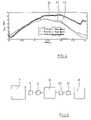
- FIG. 4shows a graph for the reconstruction of the course with respect to time of spontaneous respiration with evaluation of the difference values with respect to pressure and volume flow during two inspirations with different inspiratory volume flows.
- FIG. 5shows a functional block diagram for illustrating the design of the device.
- FIG. 6shows a functional block diagram of a modified design of the device.
- FIG. 7shows another modification of the design of the device.
- FIG. 8shows a functional block diagram of another modified design of the device.
- FIG. 9shows another modification of the device.
- FIG. 10shows another modification.
- FIG. 11shows another modification.
- FIG. 12shows another modification.
- FIG. 13shows another modified embodiment.
- FIG. 14shows another modified embodiment.
- FIG. 15shows an equivalent circuit diagram that has been modified from the diagram in FIG. 2 .
- a ventilation system 1has a driven fan 3 .
- the fan 3is driven by a motor or some other power source.
- the fan 3is connected to a control valve 4 , which has a control unit 6 and transforms a control voltage to an associated valve position.
- a pressure sensor 8 and a volume flow sensor 9are connected to a ventilator 7 , which consists essentially of the fan 3 and the control valve 4 .
- the volume flow sensor 9is typically designed as a differential pressure sensor, whose signal is converted to an associated volume flow.
- the ventilator 7is connected by a respiratory gas hose 10 and an expiration valve 11 to a ventilation mask 12 , which can be positioned over the face of a patient 13 .
- the sensors 8 , 9are connected to an evaluation unit 14 , which in turn is connected to the control unit 6 .
- FIG. 2shows an equivalent electrical circuit diagram, which reproduces the function of the lung of the patient 13 and is used in the evaluation unit 14 as a model for performing the computations.
- a volume flow generated by a volume flow source 15is supplied to the parallel connection of two flow branches.
- One of the branchescontains the series connection of the resistance 16 and the compliance 17 and a source of interference 18 , which generates an additional volume flow and represents possible activity of the patient 13 himself.
- the second flow branchcontains a leakage resistance 19 .
- the equivalent electrical circuit diagram of the respiratory tract according to FIG. 2shows that the pressure P mus of a patient produced by his active breathing activity contributes to the airway pressure P aw and thus to the flow into the lung V′ aw . Accordingly, leak identification must also take P mus into account if the leakage flow V′ L is to be adequately compensated.
- a reconstruction of this typeallows an evaluation of the spontaneous respiration and thus indirectly an evaluation of the quality of ventilation.
- itcan be decided by integration of the reconstructed values whether the patient is breathing with or against.
- more complicated methods of classificationcan derive from this a decided evaluation for the volume-controlled ventilation, for example, with respect to synchronization or the level of respiratory effort.
- FIG. 3shows the behavior with respect to time of the difference of the measured quantities between two respiratory cycles, one being an inspiratory volume flow difference 20 , and the other being a pressure difference 21 in the area of the ventilation mask 12 .
- FIG. 4shows, with respect to a first pressure curve 22 for a first respiratory cycle and a second pressure curve 23 for a second respiratory cycle, the determined reconstruction curve 24 for spontaneous respiration of the patient 13 , taking into account the volume flow difference 20 and the pressure difference 21 between two inspirations with different inspiratory volume flows.
- FIG. 5shows the device illustrated in FIG. 1 in the form of a functional block diagram.
- the ventilator 7is connected to a respiratory gas hose 10 , and the volume flow sensor 9 and the pressure sensor 8 are arranged in the area between the ventilator 7 and the respiratory gas hose 10 .
- the respiratory gas hose 10is connected to the ventilation mask 12 , and an additional volume flow sensor 25 and an additional pressure sensor 26 are positioned in the area between the respiratory gas hose 10 and the ventilation mask 12 .
- the sensorscan also be arranged only in the area between the ventilator 7 and the respiratory gas hose 10 or only in the area between the respiratory gas hose 10 and the ventilation mask 12 .
- a setup with a mass flowmeteris also possible; and in this case, a conversion to volume flow is made.
- an expiration valve 11is arranged in the area between the respiratory gas hose 10 and the ventilation mask 12 , and a discharge system 27 is arranged between the ventilator 7 and the respiratory gas hose 10 . It is also possible to arrange only the expiration valve 11 in the area between the respiratory gas hose 10 and the ventilation mask 12 or to arrange only the discharge system 27 in the area between the ventilator 7 and the respiratory gas hose 10 . Furthermore, it is possible to replace the expiration valve 11 with a discharge system 27 and the discharge system 27 with an expiration valve 11 .
- noninvasive devicescan be used to provide a connection with the patient 13 .
- the use of masks or headpiecesis possible.
- a connection between the ventilation system 1 and the patient 13can also be established by invasive coupling devices, for example, an intubation tube, a tracheostoma, or a laryngeal mask.
- the ventilation systems that are usedcan be designed for carrying out various types of ventilation, for example, control mode ventilation, assist/control mode ventilation, or assist mode ventilation.
- the methodcan be used in periodic breathing and for CPAP ventilation or APAP ventilation.
- the determination of resistance and compliancecan be made, for example, exclusively during the inspiratory or exclusively during the expiratory time intervals of the respiratory cycles. However, it is also possible to make these determinations during both the inspiratory and expiratory phases.
- FIG. 7shows the previously mentioned embodiment, in which the respiratory gas hose 10 is directly coupled with the ventilation mask 12 , and the discharge system 27 and the sensors 8 , 9 are positioned only in the area between the ventilator 7 and the respiratory gas hose 10 .
- FIG. 8shows an embodiment that is a modification of the embodiment shown in FIG. 7 , in which the discharge system 27 and the volume flow sensor 9 are positioned between the ventilator 7 and the respiratory gas hose 10 , and the pressure sensor 8 is positioned between the respiratory gas hose 10 and the ventilation mask 12 .
- the discharge system 27 and the pressure sensor 8are positioned between the ventilator 7 and the respiratory gas hose 10
- the volume flow sensor 9is positioned between the respiratory gas hose 10 and the ventilation mask 12 .
- both the pressure sensor 8 and the volume flow sensor 9are positioned between the ventilator 7 and the respiratory gas hose 10
- the expiration valve 11is positioned between the respiratory gas hose 10 and the ventilation mask 12 .
- volume flow sensor 9is arranged between the ventilator 7 and the respiratory gas hose 10 , and the expiration valve 11 and the pressure sensor 8 are positioned between the respiratory gas hose 10 and the ventilation mask 12 .
- FIG. 14shows an embodiment in which the ventilator 7 is directly coupled with the respiratory gas hose 10 , and the expiration valve 11 and both the pressure sensor 8 and the volume flow sensor 9 are positioned between the respiratory gas hose 10 and the ventilation mask 12 .
- FIG. 15shows an equivalent circuit diagram that is supplemented relative to the diagram in FIG. 2 and is used in the case of linear behavior of the system comprising the patient and the respiratory gas hose.
- the capacity 28 resulting from the volume of the hoseis taken into consideration.
- a 1( ⁇ T(RC+R L C+R L C s ) ⁇ 2RCR L C s )/K
- P FSis not equal to P aw .
- P awP aw ( s )/(1 +sT s ⁇ e sTt )
- T sis the integral-action time of the flexible respiratory gas hose with the hose connector.
- the delay time Ttcorresponds to the sound transit time through the hose.
- the parameters R, C, and R Lcan be estimated by well-known identification and parameter estimation methods for linear as well as nonlinear systems. Especially a time-distributed computation of the parameter estimation is advantageous for implementation. In this regard, recursive methods make it possible to obtain results with the greatest time proximity to the last observation period.
Landscapes
- Health & Medical Sciences (AREA)
- Emergency Medicine (AREA)
- Pulmonology (AREA)
- Engineering & Computer Science (AREA)
- Anesthesiology (AREA)
- Biomedical Technology (AREA)
- Heart & Thoracic Surgery (AREA)
- Hematology (AREA)
- Life Sciences & Earth Sciences (AREA)
- Animal Behavior & Ethology (AREA)
- General Health & Medical Sciences (AREA)
- Public Health (AREA)
- Veterinary Medicine (AREA)
- Measurement Of The Respiration, Hearing Ability, Form, And Blood Characteristics Of Living Organisms (AREA)
- Respiratory Apparatuses And Protective Means (AREA)
Abstract
Description
Paw(s)=[Pmus(s)+V′insp(s)(1+sRC)/sC]×sRLC/(1s(R+RL)C)
ΔPaw(s)=Paw,k(s)−Paw,k1(s)
ΔV′insp(s)=V′insp,k(s)−V′insp,k 1(s)
where k is the running number of the inspiration.
Pmus,k(s)=Pmus,k1(s)
a simpler relationship is obtained between the pressure difference Δpawand the flow difference ΔV′inspin the complex variable domain of the Laplace transform:
ΔPaw(s)=ΔV′insp(s)(1+sRC)RL/(1+s(R+RL)C)
P^mus(s)=(1+s(R^+R^L)C^)/sR^LC^PFS(s)−(1+sR^C^)/sC^V′FS(s)
PFS(s)/V′FS(s)=(RL×(1+sRC))/(1+s(RC+RLC+RLCs)+S2RCRLCs)
PFS,k/V′FS,k=(b0+b1Z−1)/(1+a1Z1+a2Z2)
where
Paw(s)/V′insp(s)=RL×(1+sRC)/(1+s(R+RL)+C)
Paw,k/V′insp,k=(b0+b1z1)/(1+a1z1)
where
PFS(s)=Paw(s)/(1+sTs×esTt)
can be used, in which Tsis the integral-action time of the flexible respiratory gas hose with the hose connector. The delay time Tt corresponds to the sound transit time through the hose.
Claims (29)
Applications Claiming Priority (4)
| Application Number | Priority Date | Filing Date | Title |
|---|---|---|---|
| DE10313082 | 2003-03-24 | ||
| DE10313082 | 2003-03-24 | ||
| DE10313082.9 | 2003-03-24 | ||
| PCT/DE2004/000607WO2004084980A1 (en) | 2003-03-24 | 2004-03-23 | Method and device for detecting leaks in respiratory gas supply systems |
Publications (2)
| Publication Number | Publication Date |
|---|---|
| US20060249150A1 US20060249150A1 (en) | 2006-11-09 |
| US7475685B2true US7475685B2 (en) | 2009-01-13 |
Family
ID=33038745
Family Applications (1)
| Application Number | Title | Priority Date | Filing Date |
|---|---|---|---|
| US10/550,634Expired - LifetimeUS7475685B2 (en) | 2003-03-24 | 2004-03-23 | Method and device for detecting leaks in respiratory gas supply systems |
Country Status (4)
| Country | Link |
|---|---|
| US (1) | US7475685B2 (en) |
| EP (1) | EP1605999A1 (en) |
| DE (2) | DE102004014619A1 (en) |
| WO (1) | WO2004084980A1 (en) |
Cited By (45)
| Publication number | Priority date | Publication date | Assignee | Title |
|---|---|---|---|---|
| US20070144522A1 (en)* | 2005-12-22 | 2007-06-28 | Draeger Medical Ag & Co. Kg | Device and method for determining leaks of a respirator |
| US20090241951A1 (en)* | 2008-03-31 | 2009-10-01 | Nellcor Puritan Bennett Llc | Leak-compensated pressure triggering in medical ventilators |
| US20090287070A1 (en)* | 2008-05-16 | 2009-11-19 | Nellcor Puritan Bennett Llc | Estimation Of A Physiological Parameter Using A Neural Network |
| US20100071696A1 (en)* | 2008-09-25 | 2010-03-25 | Nellcor Puritan Bennett Llc | Model-predictive online identification of patient respiratory effort dynamics in medical ventilators |
| US20100147303A1 (en)* | 2008-03-31 | 2010-06-17 | Nellcor Puritan Bennett Llc | Determination of patient circuit disconnect in leak-compensated ventilatory support |
| US20100186744A1 (en)* | 2003-07-29 | 2010-07-29 | Claude Andrieux | System and process for supplying respiratory gas under pressure or volumetrically |
| US20100218767A1 (en)* | 2009-02-27 | 2010-09-02 | Nellcor Puritan Bennett Llc | Leak-compensated respiratory mechanics estimation in medical ventilators |
| US20100218766A1 (en)* | 2009-02-27 | 2010-09-02 | Nellcor Puritan Bennett Llc | Customizable mandatory/spontaneous closed loop mode selection |
| US20100218765A1 (en)* | 2009-02-27 | 2010-09-02 | Nellcor Puritan Bennett Llc | Flow rate compensation for transient thermal response of hot-wire anemometers |
| US20100236553A1 (en)* | 2009-03-20 | 2010-09-23 | Nellcor Puritan Bennelt LLC | Leak-compensated proportional assist ventilation |
| US20100236555A1 (en)* | 2009-03-20 | 2010-09-23 | Nellcor Puritan Bennett Llc | Leak-compensated pressure regulated volume control ventilation |
| US20110126835A1 (en)* | 2009-12-01 | 2011-06-02 | Nellcor Puritan Bennett Llc | Exhalation Valve Assembly With Integrated Filter And Flow Sensor |
| US20110126837A1 (en)* | 2009-12-01 | 2011-06-02 | Nellcor Puritan Bennett Llc | Exhalation Valve Assembly With Integrated Filter |
| US20110196251A1 (en)* | 2010-02-10 | 2011-08-11 | Nellcor Puritan Bennett Llc | Leak determination in a breathing assistance system |
| USD653749S1 (en) | 2010-04-27 | 2012-02-07 | Nellcor Puritan Bennett Llc | Exhalation module filter body |
| USD655405S1 (en) | 2010-04-27 | 2012-03-06 | Nellcor Puritan Bennett Llc | Filter and valve body for an exhalation module |
| USD655809S1 (en) | 2010-04-27 | 2012-03-13 | Nellcor Puritan Bennett Llc | Valve body with integral flow meter for an exhalation module |
| US8439036B2 (en) | 2009-12-01 | 2013-05-14 | Covidien Lp | Exhalation valve assembly with integral flow sensor |
| US20130150747A1 (en)* | 2010-07-26 | 2013-06-13 | Restech S R L - Spin Off De Politecnico Di Milano | System and method for measuring the mechanical impedance of the respiratory system |
| US8469030B2 (en) | 2009-12-01 | 2013-06-25 | Covidien Lp | Exhalation valve assembly with selectable contagious/non-contagious latch |
| USD692556S1 (en) | 2013-03-08 | 2013-10-29 | Covidien Lp | Expiratory filter body of an exhalation module |
| USD693001S1 (en) | 2013-03-08 | 2013-11-05 | Covidien Lp | Neonate expiratory filter assembly of an exhalation module |
| USD701601S1 (en) | 2013-03-08 | 2014-03-25 | Covidien Lp | Condensate vial of an exhalation module |
| US8776792B2 (en) | 2011-04-29 | 2014-07-15 | Covidien Lp | Methods and systems for volume-targeted minimum pressure-control ventilation |
| USD731049S1 (en) | 2013-03-05 | 2015-06-02 | Covidien Lp | EVQ housing of an exhalation module |
| USD731065S1 (en) | 2013-03-08 | 2015-06-02 | Covidien Lp | EVQ pressure sensor filter of an exhalation module |
| USD731048S1 (en) | 2013-03-08 | 2015-06-02 | Covidien Lp | EVQ diaphragm of an exhalation module |
| USD736905S1 (en) | 2013-03-08 | 2015-08-18 | Covidien Lp | Exhalation module EVQ housing |
| US9144658B2 (en) | 2012-04-30 | 2015-09-29 | Covidien Lp | Minimizing imposed expiratory resistance of mechanical ventilator by optimizing exhalation valve control |
| USD744095S1 (en) | 2013-03-08 | 2015-11-24 | Covidien Lp | Exhalation module EVQ internal flow sensor |
| US9358355B2 (en) | 2013-03-11 | 2016-06-07 | Covidien Lp | Methods and systems for managing a patient move |
| US9364624B2 (en) | 2011-12-07 | 2016-06-14 | Covidien Lp | Methods and systems for adaptive base flow |
| US9375542B2 (en) | 2012-11-08 | 2016-06-28 | Covidien Lp | Systems and methods for monitoring, managing, and/or preventing fatigue during ventilation |
| US9498589B2 (en) | 2011-12-31 | 2016-11-22 | Covidien Lp | Methods and systems for adaptive base flow and leak compensation |
| USD775345S1 (en) | 2015-04-10 | 2016-12-27 | Covidien Lp | Ventilator console |
| US9629971B2 (en) | 2011-04-29 | 2017-04-25 | Covidien Lp | Methods and systems for exhalation control and trajectory optimization |
| US9649458B2 (en) | 2008-09-30 | 2017-05-16 | Covidien Lp | Breathing assistance system with multiple pressure sensors |
| US9675771B2 (en) | 2013-10-18 | 2017-06-13 | Covidien Lp | Methods and systems for leak estimation |
| US9814270B2 (en) | 2016-01-06 | 2017-11-14 | Adam Montgomery | Tabletop vaporizer |
| US9950135B2 (en) | 2013-03-15 | 2018-04-24 | Covidien Lp | Maintaining an exhalation valve sensor assembly |
| US9993604B2 (en) | 2012-04-27 | 2018-06-12 | Covidien Lp | Methods and systems for an optimized proportional assist ventilation |
| US10207069B2 (en) | 2008-03-31 | 2019-02-19 | Covidien Lp | System and method for determining ventilator leakage during stable periods within a breath |
| US10668239B2 (en) | 2017-11-14 | 2020-06-02 | Covidien Lp | Systems and methods for drive pressure spontaneous ventilation |
| US11517691B2 (en) | 2018-09-07 | 2022-12-06 | Covidien Lp | Methods and systems for high pressure controlled ventilation |
| US11896767B2 (en) | 2020-03-20 | 2024-02-13 | Covidien Lp | Model-driven system integration in medical ventilators |
Families Citing this family (23)
| Publication number | Priority date | Publication date | Assignee | Title |
|---|---|---|---|---|
| DE102004040659A1 (en)* | 2004-08-20 | 2006-02-23 | Weinmann Geräte für Medizin GmbH + Co. KG | Apparatus for ventilation and method for controlling a ventilator |
| JP2009519058A (en)* | 2005-12-16 | 2009-05-14 | ハミルトン・メディカル・アーゲー | Ventilator tube system |
| CN100998902B (en) | 2006-01-13 | 2010-12-08 | 深圳迈瑞生物医疗电子股份有限公司 | Method and device for mornitering and controlling flow |
| CN101002972B (en) | 2006-01-20 | 2010-09-01 | 深圳迈瑞生物医疗电子股份有限公司 | Method for judging inversed connection of flow-rate sensor, and module of its breathing mechanics measurement |
| EP2789359A3 (en)* | 2006-08-30 | 2014-12-24 | ResMed Ltd. | Determination of leak during CPAP treatment |
| WO2009123981A1 (en)* | 2008-03-31 | 2009-10-08 | Nellcor Puritan Bennett Llc | Leak-compensated proportional assist ventilation |
| DE102008048824A1 (en)* | 2008-09-22 | 2010-03-25 | Borm, Hans-Jürgen | Method and device for the automatic determination of a ventilation volume in mechanical ventilation, taking into account leaks |
| DE102009005048A1 (en) | 2009-01-13 | 2010-07-15 | Borm, Hans-Jürgen | Inspiratory leakage volume determining method for use during provision of artificial respiration to patient, involves determining real total volume by subtracting inspiration time from inspiratory total volume |
| EP2464404B1 (en) | 2009-08-11 | 2017-06-28 | ResMed Motor Technologies Inc. | Single stage, axial symmetric blower and ventilator |
| EP2368593A1 (en)* | 2010-03-26 | 2011-09-28 | Dräger Medical GmbH | Estimating a leakage flow |
| CN102892449B (en)* | 2010-05-11 | 2016-04-20 | 皇家飞利浦电子股份有限公司 | Inductance in pressure support system compensates |
| EP2590702B1 (en)* | 2010-07-09 | 2014-05-14 | Koninklijke Philips N.V. | Leak estimation using leak model identification |
| NZ703966A (en)* | 2010-07-30 | 2016-07-29 | Resmed Ltd | Methods and devices with leak detection |
| MX2014002034A (en) | 2011-08-25 | 2014-03-21 | Koninkl Philips Nv | Non-invasive ventilation measurement. |
| WO2013098686A1 (en)* | 2011-12-27 | 2013-07-04 | Koninklijke Philips Electronics N.V. | Compensation of breath delivery |
| JP6815729B2 (en)* | 2012-12-18 | 2021-01-20 | コーニンクレッカ フィリップス エヌ ヴェKoninklijke Philips N.V. | Intake pressure control in volume mode ventilation |
| CN103900840A (en)* | 2012-12-28 | 2014-07-02 | 北京谊安医疗系统股份有限公司 | Detection method and detection device for anesthesia machine controlled leakage and compliance test pipelines |
| US20180177963A1 (en)* | 2015-06-02 | 2018-06-28 | Koninklijke Philips N.V. | Non-invasive method for monitoring patient respiratory status via successive parameter estimation |
| US11027082B2 (en)* | 2015-09-28 | 2021-06-08 | Koninklijke Philps N.V. | Methods and systems to estimate compliance of a patient circuit in the presence of leak |
| JP6760398B2 (en)* | 2016-12-16 | 2020-09-23 | 株式会社村田製作所 | CPAP device |
| EP3838119B1 (en)* | 2019-12-18 | 2024-03-06 | Qaelon Medical | System for automatically detecting a clinically relevant leak |
| CN111481848B (en)* | 2020-04-24 | 2021-05-25 | 张乐 | Energy-saving ventilation equipment for civil air defense engineering |
| CN114370983B (en)* | 2021-12-29 | 2022-12-02 | 卫圣康医学科技(江苏)有限公司 | Calibration method and test method for compliance detection |
Citations (14)
| Publication number | Priority date | Publication date | Assignee | Title |
|---|---|---|---|---|
| DE2441306A1 (en) | 1973-09-07 | 1975-03-13 | Hoffmann La Roche | REGULATING PROCEDURES AND DEVICE FOR VENTILATION DEVICES |
| US4031885A (en) | 1975-10-15 | 1977-06-28 | Puritan-Bennett Corporation | Method and apparatus for determining patient lung pressure, compliance and resistance |
| DE2702125A1 (en) | 1977-01-20 | 1978-07-27 | Draegerwerk Ag | MONITORING DEVICE FOR A VENTILATION DEVICE |
| DE7701492U1 (en) | 1977-01-20 | 1981-12-17 | Drägerwerk AG, 2400 Lübeck | MONITORING DEVICE FOR A VENTILATOR |
| DE69033005T2 (en) | 1989-05-19 | 1999-09-23 | Puritan-Bennet Corp., Lenexa | PRESSURE SYSTEM FOR BREATHWAYS |
| US5970975A (en)* | 1991-11-01 | 1999-10-26 | Respironics, Inc. | Sleep apnea treatment apparatus |
| US6152129A (en) | 1996-08-14 | 2000-11-28 | Resmed Limited | Determination of leak and respiratory airflow |
| WO2002004057A1 (en) | 2000-07-11 | 2002-01-17 | Taema | Artificial ventilation apparatus |
| US20020014240A1 (en) | 1998-11-25 | 2002-02-07 | William A. Truschel | Pressure support system with a low leak alarm and method of using same |
| WO2002020076A2 (en) | 2000-09-05 | 2002-03-14 | Mallinckrodt, Inc. | Adaptive inverse control of pressure based ventilation |
| DE69523960T2 (en) | 1994-07-28 | 2002-06-20 | Interspiro Europe Ab, Lidingoe | FUNCTIONAL CONTROL OF BREATHING DEVICES |
| WO2003055552A1 (en) | 2001-12-28 | 2003-07-10 | Müfa Ag | Respiratory device |
| DE69909023T2 (en) | 1998-06-15 | 2004-05-19 | Maquet Critical Care Ab | A method to determine tube system volume in a fan |
| US7325545B2 (en)* | 2002-06-11 | 2008-02-05 | Politecnico Di Milano | System and method for the automatic detection of the expiratory flow limitation |
- 2004
- 2004-03-23USUS10/550,634patent/US7475685B2/ennot_activeExpired - Lifetime
- 2004-03-23WOPCT/DE2004/000607patent/WO2004084980A1/enactiveApplication Filing
- 2004-03-23DEDE102004014619Apatent/DE102004014619A1/ennot_activeWithdrawn
- 2004-03-23DEDE112004000944Tpatent/DE112004000944D2/ennot_activeExpired - Fee Related
- 2004-03-23EPEP04722532Apatent/EP1605999A1/ennot_activeWithdrawn
Patent Citations (14)
| Publication number | Priority date | Publication date | Assignee | Title |
|---|---|---|---|---|
| DE2441306A1 (en) | 1973-09-07 | 1975-03-13 | Hoffmann La Roche | REGULATING PROCEDURES AND DEVICE FOR VENTILATION DEVICES |
| US4031885A (en) | 1975-10-15 | 1977-06-28 | Puritan-Bennett Corporation | Method and apparatus for determining patient lung pressure, compliance and resistance |
| DE2702125A1 (en) | 1977-01-20 | 1978-07-27 | Draegerwerk Ag | MONITORING DEVICE FOR A VENTILATION DEVICE |
| DE7701492U1 (en) | 1977-01-20 | 1981-12-17 | Drägerwerk AG, 2400 Lübeck | MONITORING DEVICE FOR A VENTILATOR |
| DE69033005T2 (en) | 1989-05-19 | 1999-09-23 | Puritan-Bennet Corp., Lenexa | PRESSURE SYSTEM FOR BREATHWAYS |
| US5970975A (en)* | 1991-11-01 | 1999-10-26 | Respironics, Inc. | Sleep apnea treatment apparatus |
| DE69523960T2 (en) | 1994-07-28 | 2002-06-20 | Interspiro Europe Ab, Lidingoe | FUNCTIONAL CONTROL OF BREATHING DEVICES |
| US6152129A (en) | 1996-08-14 | 2000-11-28 | Resmed Limited | Determination of leak and respiratory airflow |
| DE69909023T2 (en) | 1998-06-15 | 2004-05-19 | Maquet Critical Care Ab | A method to determine tube system volume in a fan |
| US20020014240A1 (en) | 1998-11-25 | 2002-02-07 | William A. Truschel | Pressure support system with a low leak alarm and method of using same |
| WO2002004057A1 (en) | 2000-07-11 | 2002-01-17 | Taema | Artificial ventilation apparatus |
| WO2002020076A2 (en) | 2000-09-05 | 2002-03-14 | Mallinckrodt, Inc. | Adaptive inverse control of pressure based ventilation |
| WO2003055552A1 (en) | 2001-12-28 | 2003-07-10 | Müfa Ag | Respiratory device |
| US7325545B2 (en)* | 2002-06-11 | 2008-02-05 | Politecnico Di Milano | System and method for the automatic detection of the expiratory flow limitation |
Cited By (89)
| Publication number | Priority date | Publication date | Assignee | Title |
|---|---|---|---|---|
| US20100186744A1 (en)* | 2003-07-29 | 2010-07-29 | Claude Andrieux | System and process for supplying respiratory gas under pressure or volumetrically |
| US8800557B2 (en) | 2003-07-29 | 2014-08-12 | Covidien Lp | System and process for supplying respiratory gas under pressure or volumetrically |
| US20070144522A1 (en)* | 2005-12-22 | 2007-06-28 | Draeger Medical Ag & Co. Kg | Device and method for determining leaks of a respirator |
| US7882835B2 (en)* | 2005-12-22 | 2011-02-08 | Dräger Medical GmbH | Device and method for determining leaks of a respirator |
| US20100147303A1 (en)* | 2008-03-31 | 2010-06-17 | Nellcor Puritan Bennett Llc | Determination of patient circuit disconnect in leak-compensated ventilatory support |
| US9421338B2 (en) | 2008-03-31 | 2016-08-23 | Covidien Lp | Ventilator leak compensation |
| US8434480B2 (en) | 2008-03-31 | 2013-05-07 | Covidien Lp | Ventilator leak compensation |
| US8272379B2 (en) | 2008-03-31 | 2012-09-25 | Nellcor Puritan Bennett, Llc | Leak-compensated flow triggering and cycling in medical ventilators |
| US8272380B2 (en) | 2008-03-31 | 2012-09-25 | Nellcor Puritan Bennett, Llc | Leak-compensated pressure triggering in medical ventilators |
| US8746248B2 (en) | 2008-03-31 | 2014-06-10 | Covidien Lp | Determination of patient circuit disconnect in leak-compensated ventilatory support |
| US20090241951A1 (en)* | 2008-03-31 | 2009-10-01 | Nellcor Puritan Bennett Llc | Leak-compensated pressure triggering in medical ventilators |
| US11027080B2 (en) | 2008-03-31 | 2021-06-08 | Covidien Lp | System and method for determining ventilator leakage during stable periods within a breath |
| US10207069B2 (en) | 2008-03-31 | 2019-02-19 | Covidien Lp | System and method for determining ventilator leakage during stable periods within a breath |
| US20090241955A1 (en)* | 2008-03-31 | 2009-10-01 | Nellcor Puritan Bennett Llc | Leak-compensated flow triggering and cycling in medical ventilators |
| US20090241962A1 (en)* | 2008-03-31 | 2009-10-01 | Nellcor Puritan Bennett Llc | Ventilator leak compensation |
| US8457706B2 (en) | 2008-05-16 | 2013-06-04 | Covidien Lp | Estimation of a physiological parameter using a neural network |
| US20090287070A1 (en)* | 2008-05-16 | 2009-11-19 | Nellcor Puritan Bennett Llc | Estimation Of A Physiological Parameter Using A Neural Network |
| US20100071696A1 (en)* | 2008-09-25 | 2010-03-25 | Nellcor Puritan Bennett Llc | Model-predictive online identification of patient respiratory effort dynamics in medical ventilators |
| US9649458B2 (en) | 2008-09-30 | 2017-05-16 | Covidien Lp | Breathing assistance system with multiple pressure sensors |
| US8905024B2 (en) | 2009-02-27 | 2014-12-09 | Covidien Lp | Flow rate compensation for transient thermal response of hot-wire anemometers |
| US20100218765A1 (en)* | 2009-02-27 | 2010-09-02 | Nellcor Puritan Bennett Llc | Flow rate compensation for transient thermal response of hot-wire anemometers |
| US20100218766A1 (en)* | 2009-02-27 | 2010-09-02 | Nellcor Puritan Bennett Llc | Customizable mandatory/spontaneous closed loop mode selection |
| US20100218767A1 (en)* | 2009-02-27 | 2010-09-02 | Nellcor Puritan Bennett Llc | Leak-compensated respiratory mechanics estimation in medical ventilators |
| US8434479B2 (en) | 2009-02-27 | 2013-05-07 | Covidien Lp | Flow rate compensation for transient thermal response of hot-wire anemometers |
| US8424521B2 (en) | 2009-02-27 | 2013-04-23 | Covidien Lp | Leak-compensated respiratory mechanics estimation in medical ventilators |
| US8978650B2 (en) | 2009-03-20 | 2015-03-17 | Covidien Lp | Leak-compensated proportional assist ventilation |
| US8973577B2 (en) | 2009-03-20 | 2015-03-10 | Covidien Lp | Leak-compensated pressure regulated volume control ventilation |
| US20100236553A1 (en)* | 2009-03-20 | 2010-09-23 | Nellcor Puritan Bennelt LLC | Leak-compensated proportional assist ventilation |
| US20100236555A1 (en)* | 2009-03-20 | 2010-09-23 | Nellcor Puritan Bennett Llc | Leak-compensated pressure regulated volume control ventilation |
| US8448641B2 (en) | 2009-03-20 | 2013-05-28 | Covidien Lp | Leak-compensated proportional assist ventilation |
| US8267085B2 (en) | 2009-03-20 | 2012-09-18 | Nellcor Puritan Bennett Llc | Leak-compensated proportional assist ventilation |
| US8418691B2 (en) | 2009-03-20 | 2013-04-16 | Covidien Lp | Leak-compensated pressure regulated volume control ventilation |
| US8469030B2 (en) | 2009-12-01 | 2013-06-25 | Covidien Lp | Exhalation valve assembly with selectable contagious/non-contagious latch |
| US8469031B2 (en) | 2009-12-01 | 2013-06-25 | Covidien Lp | Exhalation valve assembly with integrated filter |
| US20110126837A1 (en)* | 2009-12-01 | 2011-06-02 | Nellcor Puritan Bennett Llc | Exhalation Valve Assembly With Integrated Filter |
| US20110126835A1 (en)* | 2009-12-01 | 2011-06-02 | Nellcor Puritan Bennett Llc | Exhalation Valve Assembly With Integrated Filter And Flow Sensor |
| US9987457B2 (en) | 2009-12-01 | 2018-06-05 | Covidien Lp | Exhalation valve assembly with integral flow sensor |
| US9205221B2 (en) | 2009-12-01 | 2015-12-08 | Covidien Lp | Exhalation valve assembly with integral flow sensor |
| US8439036B2 (en) | 2009-12-01 | 2013-05-14 | Covidien Lp | Exhalation valve assembly with integral flow sensor |
| US8439037B2 (en) | 2009-12-01 | 2013-05-14 | Covidien Lp | Exhalation valve assembly with integrated filter and flow sensor |
| US8939150B2 (en) | 2010-02-10 | 2015-01-27 | Covidien Lp | Leak determination in a breathing assistance system |
| US11033700B2 (en) | 2010-02-10 | 2021-06-15 | Covidien Lp | Leak determination in a breathing assistance system |
| US9254369B2 (en) | 2010-02-10 | 2016-02-09 | Covidien Lp | Leak determination in a breathing assistance system |
| US8707952B2 (en) | 2010-02-10 | 2014-04-29 | Covidien Lp | Leak determination in a breathing assistance system |
| US20110196251A1 (en)* | 2010-02-10 | 2011-08-11 | Nellcor Puritan Bennett Llc | Leak determination in a breathing assistance system |
| US10463819B2 (en) | 2010-02-10 | 2019-11-05 | Covidien Lp | Leak determination in a breathing assistance system |
| USD655809S1 (en) | 2010-04-27 | 2012-03-13 | Nellcor Puritan Bennett Llc | Valve body with integral flow meter for an exhalation module |
| USD655405S1 (en) | 2010-04-27 | 2012-03-06 | Nellcor Puritan Bennett Llc | Filter and valve body for an exhalation module |
| USD653749S1 (en) | 2010-04-27 | 2012-02-07 | Nellcor Puritan Bennett Llc | Exhalation module filter body |
| US10791961B2 (en)* | 2010-07-26 | 2020-10-06 | Restech S.R.L. | System and method for measuring the mechanical impedance of the respiratory system |
| US20130150747A1 (en)* | 2010-07-26 | 2013-06-13 | Restech S R L - Spin Off De Politecnico Di Milano | System and method for measuring the mechanical impedance of the respiratory system |
| US10850056B2 (en) | 2011-04-29 | 2020-12-01 | Covidien Lp | Methods and systems for exhalation control and trajectory optimization |
| US8776792B2 (en) | 2011-04-29 | 2014-07-15 | Covidien Lp | Methods and systems for volume-targeted minimum pressure-control ventilation |
| US9629971B2 (en) | 2011-04-29 | 2017-04-25 | Covidien Lp | Methods and systems for exhalation control and trajectory optimization |
| US11638796B2 (en) | 2011-04-29 | 2023-05-02 | Covidien Lp | Methods and systems for exhalation control and trajectory optimization |
| US10543327B2 (en) | 2011-12-07 | 2020-01-28 | Covidien Lp | Methods and systems for adaptive base flow |
| US9364624B2 (en) | 2011-12-07 | 2016-06-14 | Covidien Lp | Methods and systems for adaptive base flow |
| US11497869B2 (en) | 2011-12-07 | 2022-11-15 | Covidien Lp | Methods and systems for adaptive base flow |
| US9498589B2 (en) | 2011-12-31 | 2016-11-22 | Covidien Lp | Methods and systems for adaptive base flow and leak compensation |
| US11833297B2 (en) | 2011-12-31 | 2023-12-05 | Covidien Lp | Methods and systems for adaptive base flow and leak compensation |
| US10709854B2 (en) | 2011-12-31 | 2020-07-14 | Covidien Lp | Methods and systems for adaptive base flow and leak compensation |
| US10806879B2 (en) | 2012-04-27 | 2020-10-20 | Covidien Lp | Methods and systems for an optimized proportional assist ventilation |
| US9993604B2 (en) | 2012-04-27 | 2018-06-12 | Covidien Lp | Methods and systems for an optimized proportional assist ventilation |
| US9144658B2 (en) | 2012-04-30 | 2015-09-29 | Covidien Lp | Minimizing imposed expiratory resistance of mechanical ventilator by optimizing exhalation valve control |
| US9375542B2 (en) | 2012-11-08 | 2016-06-28 | Covidien Lp | Systems and methods for monitoring, managing, and/or preventing fatigue during ventilation |
| US11229759B2 (en) | 2012-11-08 | 2022-01-25 | Covidien Lp | Systems and methods for monitoring, managing, and preventing fatigue during ventilation |
| US10543326B2 (en) | 2012-11-08 | 2020-01-28 | Covidien Lp | Systems and methods for monitoring, managing, and preventing fatigue during ventilation |
| USD731049S1 (en) | 2013-03-05 | 2015-06-02 | Covidien Lp | EVQ housing of an exhalation module |
| USD744095S1 (en) | 2013-03-08 | 2015-11-24 | Covidien Lp | Exhalation module EVQ internal flow sensor |
| USD731065S1 (en) | 2013-03-08 | 2015-06-02 | Covidien Lp | EVQ pressure sensor filter of an exhalation module |
| USD692556S1 (en) | 2013-03-08 | 2013-10-29 | Covidien Lp | Expiratory filter body of an exhalation module |
| USD693001S1 (en) | 2013-03-08 | 2013-11-05 | Covidien Lp | Neonate expiratory filter assembly of an exhalation module |
| USD736905S1 (en) | 2013-03-08 | 2015-08-18 | Covidien Lp | Exhalation module EVQ housing |
| USD701601S1 (en) | 2013-03-08 | 2014-03-25 | Covidien Lp | Condensate vial of an exhalation module |
| USD731048S1 (en) | 2013-03-08 | 2015-06-02 | Covidien Lp | EVQ diaphragm of an exhalation module |
| US9358355B2 (en) | 2013-03-11 | 2016-06-07 | Covidien Lp | Methods and systems for managing a patient move |
| US11559641B2 (en) | 2013-03-11 | 2023-01-24 | Covidien Lp | Methods and systems for managing a patient move |
| US10639441B2 (en) | 2013-03-11 | 2020-05-05 | Covidien Lp | Methods and systems for managing a patient move |
| US9950135B2 (en) | 2013-03-15 | 2018-04-24 | Covidien Lp | Maintaining an exhalation valve sensor assembly |
| US9675771B2 (en) | 2013-10-18 | 2017-06-13 | Covidien Lp | Methods and systems for leak estimation |
| US11235114B2 (en) | 2013-10-18 | 2022-02-01 | Covidien Lp | Methods and systems for leak estimation |
| US10207068B2 (en) | 2013-10-18 | 2019-02-19 | Covidien Lp | Methods and systems for leak estimation |
| USD775345S1 (en) | 2015-04-10 | 2016-12-27 | Covidien Lp | Ventilator console |
| US9814270B2 (en) | 2016-01-06 | 2017-11-14 | Adam Montgomery | Tabletop vaporizer |
| US11559643B2 (en) | 2017-11-14 | 2023-01-24 | Covidien Lp | Systems and methods for ventilation of patients |
| US10668239B2 (en) | 2017-11-14 | 2020-06-02 | Covidien Lp | Systems and methods for drive pressure spontaneous ventilation |
| US11931509B2 (en) | 2017-11-14 | 2024-03-19 | Covidien Lp | Systems and methods for drive pressure spontaneous ventilation |
| US11517691B2 (en) | 2018-09-07 | 2022-12-06 | Covidien Lp | Methods and systems for high pressure controlled ventilation |
| US11896767B2 (en) | 2020-03-20 | 2024-02-13 | Covidien Lp | Model-driven system integration in medical ventilators |
Also Published As
| Publication number | Publication date |
|---|---|
| DE112004000944D2 (en) | 2006-02-09 |
| DE102004014619A1 (en) | 2005-03-17 |
| EP1605999A1 (en) | 2005-12-21 |
| WO2004084980A1 (en) | 2004-10-07 |
| US20060249150A1 (en) | 2006-11-09 |
Similar Documents
| Publication | Publication Date | Title |
|---|---|---|
| US7475685B2 (en) | Method and device for detecting leaks in respiratory gas supply systems | |
| US11033700B2 (en) | Leak determination in a breathing assistance system | |
| JP4307811B2 (en) | Operating system and respiratory system for examination of pulmonary mechanics of respiratory system | |
| US8312879B2 (en) | Method and apparatus for airway compensation control | |
| JP2582010B2 (en) | Monitoring device for respiratory muscle activity | |
| AU2011218803B2 (en) | A method for estimating at least one parameter at a patient circuit wye in a medical ventilator providing ventilation to a patient | |
| JP4613213B2 (en) | A device that monitors the biomechanical movement of the respiratory organ of a subject and controls the ventilator based on the biomechanical movement | |
| US5876352A (en) | Process for determining the mechanical properties of the respiratory system of a respirated patient and device for carrying out the process | |
| CN103379856B (en) | System and method for determining carbon dioxide excreted during non-invasive ventilation | |
| US8960192B2 (en) | System and method for quantifying lung compliance in a self-ventilating subject | |
| EP2571423B1 (en) | System for estimating upper airway resistance and lung compliance employing induced central apneas | |
| JP6058676B2 (en) | Upper airway resistance measuring device | |
| US9295796B2 (en) | Breathing system with flow estimation | |
| JP6908583B2 (en) | Methods and systems for estimating patient airway flow and leak flow for non-invasive ventilation | |
| GB2077444A (en) | Determining at least two parameters of a patient's respiratory system | |
| CN102307521B (en) | Determining elastance and resistance | |
| CN107690310B (en) | Non-invasive method for monitoring patient respiratory status via continuous parameter estimation | |
| JP5695573B2 (en) | System and method for determination of functional residual capacity of a subject | |
| JPS61100231A (en) | respiratory monitoring device | |
| KUREš | An additive method for airway resistance measurement |
Legal Events
| Date | Code | Title | Description |
|---|---|---|---|
| AS | Assignment | Owner name:WEINMANN GERATE FUR MEDIZIN GMBH & CO. KG, GERMANY Free format text:ASSIGNMENT OF ASSIGNORS INTEREST;ASSIGNORS:DIETZ, FLORIAN;WEDLER, WOLFGANG;GOBEL, CHRISTOF;REEL/FRAME:018123/0625 Effective date:20050829 | |
| STCF | Information on status: patent grant | Free format text:PATENTED CASE | |
| FPAY | Fee payment | Year of fee payment:4 | |
| FPAY | Fee payment | Year of fee payment:8 | |
| AS | Assignment | Owner name:LOEWENSTEIN MEDICAL TECHNOLOGY GMBH + CO. KG, GERMANY Free format text:CHANGE OF NAME;ASSIGNOR:WEINMANN GERAETE FUER MEDIZIN GMBH + CO. KG;REEL/FRAME:040617/0177 Effective date:20160622 Owner name:LOEWENSTEIN MEDICAL TECHNOLOGY GMBH + CO. KG, GERM Free format text:CHANGE OF NAME;ASSIGNOR:WEINMANN GERAETE FUER MEDIZIN GMBH + CO. KG;REEL/FRAME:040617/0177 Effective date:20160622 | |
| FEPP | Fee payment procedure | Free format text:PAT HOLDER NO LONGER CLAIMS SMALL ENTITY STATUS, ENTITY STATUS SET TO UNDISCOUNTED (ORIGINAL EVENT CODE: STOL); ENTITY STATUS OF PATENT OWNER: LARGE ENTITY | |
| AS | Assignment | Owner name:LOEWENSTEIN MEDICAL TECHNOLOGY S.A., LUXEMBOURG Free format text:ASSIGNMENT OF ASSIGNORS INTEREST;ASSIGNOR:LOEWENSTEIN MEDICAL TECHNOLOGY GMBH + CO. KG;REEL/FRAME:040950/0536 Effective date:20170110 | |
| MAFP | Maintenance fee payment | Free format text:PAYMENT OF MAINTENANCE FEE, 12TH YEAR, LARGE ENTITY (ORIGINAL EVENT CODE: M1553); ENTITY STATUS OF PATENT OWNER: LARGE ENTITY Year of fee payment:12 |