US7475333B2 - Defining form formats with layout items that present data of business application - Google Patents
Defining form formats with layout items that present data of business applicationDownload PDFInfo
- Publication number
- US7475333B2 US7475333B2US09/872,515US87251501AUS7475333B2US 7475333 B2US7475333 B2US 7475333B2US 87251501 AUS87251501 AUS 87251501AUS 7475333 B2US7475333 B2US 7475333B2
- Authority
- US
- United States
- Prior art keywords
- layout
- view
- items
- nodes
- item
- Prior art date
- Legal status (The legal status is an assumption and is not a legal conclusion. Google has not performed a legal analysis and makes no representation as to the accuracy of the status listed.)
- Expired - Lifetime, expires
Links
Images


Classifications
- G—PHYSICS
- G06—COMPUTING OR CALCULATING; COUNTING
- G06Q—INFORMATION AND COMMUNICATION TECHNOLOGY [ICT] SPECIALLY ADAPTED FOR ADMINISTRATIVE, COMMERCIAL, FINANCIAL, MANAGERIAL OR SUPERVISORY PURPOSES; SYSTEMS OR METHODS SPECIALLY ADAPTED FOR ADMINISTRATIVE, COMMERCIAL, FINANCIAL, MANAGERIAL OR SUPERVISORY PURPOSES, NOT OTHERWISE PROVIDED FOR
- G06Q10/00—Administration; Management
- G06Q10/10—Office automation; Time management
Definitions
- the present inventiongenerally relates to computer technology, and, more particularly, relates to computers that define formats with layout items to present data of a business application.
- a “form”is a printed or typed document with blank spaces for insertion of required or requested information.
- a formis convenient for communication, for example, between a person and an organization.
- the organizationis, for example, a governmental institution or a business enterprise.
- the documentis a filled-in form.
- the formcontains a standardized portion for defining name and date fields (i.e. the “form”) and a specialized portion for the particular name and particular date.
- a “form”stands for any electronic document with predefined format that contains blank fields for filling with data.
- a “filled-in form” or “final document”is a form where the blank fields are already filled with data.
- the organizationsuse business application programs to organize information flow within the organization or to communicate to and from the organization.
- Application programsare, for example, programs to assist customer relationship management (CRM), finance management, and human resource management.
- CRMcustomer relationship management
- finance managementfinance management
- human resource managementAlthough the application programs are different and are often customized to the organization, it is common for most of them that information flow leaving the organization uses the final document on a traditional medium, such as paper.
- an invoice formhas pages (e.g., sheets of paper), text areas (e.g., for printing positions to be invoiced, often in tables; greetings to the recipient), an address area (e.g., for printing recipients'address), and a graphic area (e.g., for printing a logotype of the sender).
- pagese.g., sheets of paper
- text arease.g., for printing positions to be invoiced, often in tables; greetings to the recipient
- an address areae.g., for printing recipients'address
- a graphic areae.g., for printing a logotype of the sender
- Form definitionscomprise, for example, page breaks, line breaks, fonts indicators, position information, indent, tabulators, protection against line breaks in paragraph, and others.
- a form designer(hereinafter “user”) creates a new form by a so-called “form builder”, a computer program that resembles a commercially available text and image processing program.
- Logical combinations of layout itemsare coded by a programming language, thus the user must be familiar with this.
- an output programreads data from the application program, instantiates the form and prints the final documents.
- the output programreceives the data via a predefined form-interface from the application program.
- the present inventionrelates to a method for defining the format of a form by a computer, the form having pluralities of layout items, the layout items defining the presentation of data of a business application.
- the methodcomprises the following steps: providing a logic view with nodes to represent the layout items, the logic view (a) to visualize structure information of the form, (b) to visualize a processing order of the layout items by the position of the nodes, (c) to visualize at least one of the nodes as a selected node to represent a selected layout item; providing a property view to display properties of the selected layout item; providing a layout view to display the layout items, wherein the selected layout item is highlighted; modifying the selected layout item and the processing order through interaction with a user; and creating a form definition document.
- Presenting the selection simultaneously in logic, property and layout viewsassist the user to modify the selected layout item while looking at the place of the item in the structure and looking at the visual appearance of the item. Coding in a program language is not required. Preferably, the steps are performed in a graphical user interface.
- the logic viewis provided as a tree view and the nodes are tree nodes so that the processing order is visualized by a root node, a plurality of branch nodes, and a plurality of leave nodes.
- the tree view with the tree nodesis a convenient technical representation of the processing order that is easily understood by the user.
- the plurality of branch nodescomprise condition nodes to process layout items depending on logical statements in the nodes.
- nodesare optionally processed depending on logical statements.
- Logical operations that are assigned to the tree nodesare, for example, logical AND-operation and OR-operations; logical operands are constants and other mathematical expressions.
- modifying the processing order through interactioncomprises to change the position of the tree nodes.
- the usersimply changes the order of the nodes without changing any coding in a programming language. This feature is convenient to save training efforts for the user.
- providing the property view and providing the layout vieware performed for a graphical user interface on a single screen.
- the step modifyingcomprises to verify the compatibility of layout items and processing order with a predefined data interface of the business application.
- Verifying compatibility and compliance with the predefined interfacealleviates the user from constantly looking up in interface specifications. Noncompliant modifications are not allowed. Training efforts for the users are reduced.
- a form printing programis generated from the form definition document, the form printing program is called by the business application to print the final document.
- a computerdefines the format of a form, the form has a plurality of layout items, the layout items define the presentation of data of a business application, the computer comprises: a display for providing a tree view with tree nodes to represent the layout items, the tree view (a) to visualize structure information of the form, (b) to visualize a processing order of the layout items by the position of the tree nodes, (c) to visualize at least one of the tree nodes as a selected node to represent a selected layout item; for providing a property view to display properties of the selected layout item, the properties with logical statements for conditionally processing the items; for providing a layout view to display the layout items, wherein the selected layout item is highlighted; interaction means for modifying the selected layout item and the processing order through interaction with a user who changes the position of the tree nodes; and storing means for creating a form definition document.
- the computerfurther comprises verification means to verify the compatibility of layout items and processing order with a predefined data interface of the business application.
- a computer program producthas computer program code instructions for defining the format of a form, the form has layout items to define data presentation of a business application, the computer program instructions cause a processor to execute the following steps: providing a logic view with nodes to represent the layout items, the logic view (a) to visualize structure information of the form, (b) to visualize a processing order of the layout items by the position of the nodes, (c) to visualize at least one of the nodes as a selected node to represent a selected layout item; providing a property view to display properties of the selected layout item; providing a layout view to display the layout items, wherein the selected layout item is highlighted; modifying the selected layout item and the processing order through interaction with a user; and creating a form definition document.
- the computer program code instructionscause the processor to execute the step providing logic view such that the logic view is provided as a tree view that visualizes the processing order by a root node, a plurality of branch nodes, and a plurality of leave nodes.
- the computer program code instructionscause the processor to execute the step providing logic view such that the plurality of branch nodes comprise condition nodes to process layout items depending on logical statements in the nodes.
- the computer program code instructionscause the processor to execute the step modifying the processing order through user interaction to change the position of tree nodes.
- the computer program code instructionscauses the processor to execute the steps providing logic view, providing property view and providing layout view are performed for a graphical user interface on a single screen.
- the computer program code instructionscause the processor to execute the step modifying such to verify the compatibility of layout items and processing order with a predefined data interface of the business application.
- FIG. 1illustrates a simplified block diagram of a computer network system having a plurality of computers
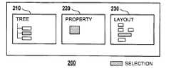
- FIG. 2illustrates a simplified screen diagram of a graphical user interface with a tree view, a property view, and a layout view according to the present invention
- FIG. 3illustrates a simplified screen diagram of the tree view of FIG. 2 with tree nodes, wherein a node is being selected;
- FIG. 4illustrates a simplified screen diagram of the property view, properties for the selected node of FIG. 3 being displayed
- FIG. 5illustrates a simplified screen diagram of the layout view, the layout item for the selected node of FIG. 3 being highlighted;
- FIG. 6illustrates a simplified screen diagram of the tree view of FIG. 3 with tree nodes arranged in hierarchy
- FIG. 7illustrates a simplified flow chart diagram of a method according to the present invention.
- FIG. 8illustrates a further method step of modifying a processing order by illustration of tree node positions
- FIG. 9illustrates a simplified block diagram of the computer network system with a design computer and an application computer.
- Computers 900 - 902are coupled via intercomputer network 990 .
- Computer 900comprises processor 910 , memory 920 , bus 930 , and, optionally, input device 940 and output device 950 (I/O devices, user interface 960 ).
- the inventionis present by computer program product 100 (CPP), program carrier 970 and program signal 980 , collectively “program”.
- computer 901 / 902is sometimes referred to as “remote computer”, computer 901 / 902 is, for example, a server, a router, a peer device or other common network node, and typically comprises many or all of the elements described relative to computer 900 .
- Computer 900is, for example, a conventional personal computer (PC), a desktop and hand-held device, a multiprocessor computer, a pen computer, a microprocessor-based or programmable consumer electronics, a minicomputer, a mainframe computer, a personal mobile computing device, a mobile phone, a portable or stationary personal computer, a palmtop computer or the like.
- PCpersonal computer
- desktop and hand-held devicea multiprocessor computer
- pen computera microprocessor-based or programmable consumer electronics
- minicomputera mainframe computer
- a personal mobile computing devicea mobile phone
- portable or stationary personal computera palmtop computer or the like.
- Processor 910is, for example, a central processing unit (CPU), a micro-controller unit (MCU), digital signal processor (DSP), or the like.
- CPUcentral processing unit
- MCUmicro-controller unit
- DSPdigital signal processor
- Memory 920symbolizes elements that temporarily or permanently store data and instructions. Although memory 920 is conveniently illustrated as part of computer 900 , memory functions can also be implemented in network 990 , in computers 901 / 902 and in processor 910 itself (e.g., cache, register), or elsewhere. Memory 920 can be a read only memory (ROM), a random access memory (RAM), or a memory with other access options.
- ROMread only memory
- RAMrandom access memory
- Memory 920is physically implemented by computer-readable media, such as, for example: (a) magnetic media, like a hard disk, a floppy disk, or other magnetic disk, a tape, a cassette tape; (b) optical media, like optical disk (CD-ROM, digital versatile disk - DVD); (c) semiconductor media, like DRAM, SRAM, EPROM, EEPROM, memory stick, or by any other media, like paper.
- computer-readable mediasuch as, for example: (a) magnetic media, like a hard disk, a floppy disk, or other magnetic disk, a tape, a cassette tape; (b) optical media, like optical disk (CD-ROM, digital versatile disk - DVD); (c) semiconductor media, like DRAM, SRAM, EPROM, EEPROM, memory stick, or by any other media, like paper.
- memory 920is distributed across different media. Portions of memory 920 can be removable or non-removable.
- computer 900uses devices well known in the art such as, for example, disk drives, tape drives.
- Memory 920stores support modules such as, for example, a basic input output system (BIOS), an operating system (OS), a program library, a compiler, an interpreter, and a text-processing tool.
- support modulesare commercially available and can be installed on computer 900 by those of skill in the art. For simplicity, these modules are not illustrated.
- CPP 100comprises program instructions and—optionally—data that cause processor 910 to execute method steps of the present invention. Method steps are explained with more detail below.
- CPP 100defines the operation of computer 900 and its interaction in system network system 999 .
- CPP 100can be available as source code in any programming language, and as object code (“binary code”) in a compiled form.
- object code(“binary code”) in a compiled form.
- Persons of skill in the artcan use CPP 100 in connection with any of the above support modules (e.g., compiler, interpreter, operating system).
- CPP 100is illustrated as being stored in memory 920 , CPP 100 can be located elsewhere. CPP 100 can also be embodied in carrier 970 .
- Carrier 970is illustrated outside computer 900 .
- carrier 970is conveniently inserted into input device 940 .
- Carrier 970is implemented as any computer readable medium, such as a medium largely explained above (cf. memory 920 ).
- carrier 970is an article of manufacture comprising a computer readable medium having computer readable program code means embodied therein for executing the method of the present invention.
- program signal 980can also embody computer program 100 . Signal 980 travels on network 990 to computer 900 .
- program carrier 970Having described CPP 100 , program carrier 970 , and program signal 980 in connection with computer 900 is convenient.
- program carrier 971 / 972(not shown) and program signal 981 / 982 embody computer program product (CPP) 101 / 102 to be executed by processor 911 / 912 (not shown) in computers 901 / 902 , respectively.
- CPPcomputer program product
- Input device 940symbolizes a device that provides data and instructions for processing by computer 900 .
- device 940is a keyboard, a pointing device (e.g., mouse, trackball, cursor direction keys), microphone, joystick, game pad, scanner.
- a wireless receivere.g., with satellite dish or terrestrial antenna
- a sensore.g., a thermometer
- a countere.g., goods counter in a factory.
- Input device 940can serve to read carrier 970 .
- Output device 950symbolizes a device that presents instructions and data that have been processed.
- a monitor or other type of display(cathode ray tube (CRT), flat panel display, liquid crystal display (LCD), a speaker, a printer, a plotter, a vibration alert device.
- output device 950communicates with the user, but it can also communicate with further computers.
- Input device 940 and output device 950can be combined to a single device; any device 940 and 950 can be provided optional.
- Bus 930 and network 990provide logical and physical connections by conveying instruction and data signals. While connections inside computer 900 are conveniently referred to as “bus 930 ”, connections between computers 900 - 902 are referred to as “network 990 ”. Devices 940 and 950 are coupled to computer 900 by bus 930 (as illustrated) or by network 990 (optional). While the signals inside computer 900 are mostly electrical signals, the signals in network are electrical, magnetic, optical or wireless (radio) signals.
- Networking environmentsare commonplace in offices, enterprise-wide computer networks, intranets and the internet (i.e. world wide web). The physical distance between a remote computer and computer 900 is not important.
- Network 990can be a wired or a wireless network.
- network 990is, for example, a local area network (LAN), a wide area network (WAN), a public switched telephone network (PSTN); a Integrated Services Digital Network (ISDN), an infra-red (IR) link, a radio link, like Universal Mobile Telecommunications System (UMTS), Global System for Mobile Communication (GSM), Code Division Multiple Access (CDMA), or satellite link.
- LANlocal area network
- WANwide area network
- PSTNpublic switched telephone network
- ISDNIntegrated Services Digital Network
- IRinfra-red
- radio linklike Universal Mobile Telecommunications System (UMTS), Global System for Mobile Communication (GSM), Code Division Multiple Access (CDMA), or satellite link.
- UMTSUniversal Mobile Telecommunications System
- GSMGlobal System for
- Transmission protocols and data formatsare know, for example, as transmission control protocol/internet protocol (TCP/IP), hyper text transfer protocol (HTTP), secure HTTP, wireless application protocol, unique resource locator (URL), a unique resource identifier (URI), hyper text markup language HTML, extensible markup language (XML), extensible hyper text markup language (XHTML), wireless application markup language (WML), etc.
- TCP/IPtransmission control protocol/internet protocol
- HTTPhyper text transfer protocol
- HTTPsecure HTTP
- wireless application protocolunique resource locator
- URLunique resource locator
- URIunique resource identifier
- HTMLhyper text markup language
- XMLextensible markup language
- XHTMLextensible hyper text markup language
- WMLwireless application markup language
- An interfacecan be, for example, a serial port interface, a parallel port interface, a game port, a universal serial bus (USB) interface, an internal or external modem, a video adapter, or a sound card.
- USBuniversal serial bus
- FIG. 2illustrates a simplified screen diagram of graphical user interface 200 with tree view 210 (TREE′′), property view 220 (PROPERTY′′), and layout view 230 (“LAYOUT”) according to the present invention.
- tree view 210is a logic view. Details for each view are presented in FIGS. 3-5 , respectively.
- selecting and highlightingis illustrated by hatching. It is known in the art that the user can select an object on a screen, for example, by double-clicking with a mouse, by pressing predefined keys, or otherwise. Usually, the object that is selected is also highlighted.
- graphical user interfacehas tree view 210 on the left side of display 950 (cf. FIGS. 1 , 9 ), property view 220 in the center, and layout view 230 on the right side.
- FIG. 3illustrates a simplified screen diagram of tree view 210 of FIG. 2 with tree nodes 211 - 213 and 251 - 255 .
- Node 211 at top positionstands for global settings of the form.
- Node 212 at center positionhas further nodes 251 - 255 with labels to visualize further structure information: node 251 for a logotype at a predetermined position in the form (“LOGO”), node 252 for an address (“ADDRESS”), node 253 for further information (“INFO”), node 254 for a main text (“MAIN”), and node 255 for further information in the lower part of the form (“FOOTER”).
- the labels of nodes 251 - 255correspond to functions (structure) of items 351 - 355 (cf. FIG.
- the filled-in formi.e. final document
- the filled-in formhas a logotype with a bitmap symbol of the sender, a main portion with a table, the recipients' address, and the footer stating the bank account number of the sender.
- Node 213 at the lower positionstands for further processing (“NEXT”), not relevant to the present invention.
- nodes 251 - 255correspond to layout items (cf. FIG. 5 ).
- Node 254is being selected (hatched).
- Tree view 210is a tool that assists the user to navigate within the form as explained in the following.
- FIG. 4illustrates a simplified screen diagram of property view 220 .
- Properties for selected node 254 “MAIN” of FIG. 3are displayed.
- the formprints invoice details only if customer is identified as “LH” and if a monetary value exceeds 0.10 currency units.
- property view 220indicates logical statement 554 for processing the layout item that is identified by selected node 254 .
- FIG. 5illustrates a simplified screen diagram of layout view 230 in that layout item 354 for the selected node 254 of FIG. 3 is highlighted.
- the userarranges the layout items by a layout and texts editor; the editors can display toolbars, grid lines, rulers, zoom lenses, spell checker or other convenient editing means; such editors are well known in the art and therefore not further described.
- Layout view 230is a pre-view and corresponds to form 300 being to be provided by output device 551 . According to the present invention, any selecting by user is forwarded to the other view. In does not matter whether the user selects a node in view 210 or a layout item in view 230 . Selection is effective in all 3 views 210 - 230 .
- the layout itemscan be tables, such as in an invoice.
- FIG. 6illustrates a simplified screen diagram of tree view 210 of FIG. 3 with tree nodes arranged in hierarchy.
- Arabic numbersindicate a preferred processing order 1 to 10. The user has defined the order by a hierarchy. Nodes that have successors are indicated by square and diamond symbols; nodes that do not have successors are indicated by triangle symbols.
- the nodes in FIG. 6are: a root node (“primary”node, square 1 ); a plurality of branch nodes (“secondary”node, squares 2 , 5 , 10 and diamond 7 ); and a plurality of leaf nodes, “terminal”node triangles 3 , 4 , 6 , 8 , 9 ).
- tree nodesare shaped according to their function.
- the optional continuation of tree 210is represented by ellipsis (“. . . ”).
- FIG. 7illustrates a simplified flow chart diagram of method 400 according to the present invention.
- Method 400is a method for defining the format of form 300 (cf. FIG. 5 ) by computer 900 (cf. FIGS. 1 , 9 ), form 300 having pluralities of layout items 351 - 355 that define the presentation of data of a business application.
- Method 400comprises the following steps: providing 410 logic view, providing 420 property view, providing 430 layout view, modifying 440 selected layout item, and creating 450 form definition document.
- design computer 900cf. FIGS. 1 , 9
- computer program product 100a method for defining the format of form 300 (cf. FIG. 5 ) by computer 900 (cf. FIGS. 1 , 9 ), form 300 having pluralities of layout items 351 - 355 that define the presentation of data of a business application.
- Method 400comprises the following steps: providing 410 logic view, providing 420 property view, providing 430 layout view, modifying 440 selected layout item, and creating 450 form definition document.
- design computer 900cf. FIGS. 1 ,
- step providing 410 logic view(with nodes 211 - 213 and 251 - 255 to represent layout items 351 - 355 ), computer 900 provides view 210 to (a) to visualize structure information of form 300 , (b) to visualize the processing order of layout items 351 - 355 by the position of nodes 211 - 213 and 251 - 255 (details in FIG. 6 ), and (c) to visualize at least one of nodes 211 - 213 , 251 - 255 as selected node 254 (cf. FIG. 3 ) to represent selected layout item 354 (cf. FIG. 5 ).
- step providing 420 property viewcomputer 900 provides property view 220 to display properties of the selected layout item 354 , as explained in the example of FIG. 4 .
- step providing 430 layout viewcomputer 900 provides layout view 230 to display layout items 351 - 355 , wherein selected layout item 354 is highlighted.
- step modifying 440 selected layout item and processing ordercomputer 900 modifies selected layout item 354 or processing order 1 - 10 (cf. FIG. 6 ) through interaction with the user.
- step creating 450 form definition document 301computer 900 stores layout information confirmed in the previous steps in document 301 (cf. FIG. 9 ).
- data objectsare stored in a programming language according to predefined rules (e.g., XML rules).
- step providing 410 logic viewthe view is provided as tree view 210 and the nodes are tree nodes.
- processing order 1 - 10is visualized by root node 1 , a plurality of branch nodes 2 , 5 , 7 , and a plurality of leave nodes 3 , 4 , 6 , 8 , and 9 .
- step providing 410 logic viewcomputer 900 visualizes structure information by labels (LOGO 251 , ADDRESS 252 , INFO 253 , MAIN 254 , FOOTER 255 ) at the nodes that correspond to functions of items 351 - 355 .
- labels(LOGO 251 , ADDRESS 252 , INFO 253 , MAIN 254 , FOOTER 255 ) at the nodes that correspond to functions of items 351 - 355 .
- form definition document 301(cf. FIG. 9 ) has been created
- a form printing programis generated from document 301 .
- the form printing programis called by the business application to print the final document.
- FIG. 8illustrates method step modifying 440 processing order 1 - 10 by illustration of tree node positions.
- FIGS. 8A to 8Cillustrate on the left sides the positions of tree nodes 211 - 213 before modifying (order 211 , 212 , 213 ), and illustrate on the right sides the positions of tree nodes after modifying.
- the processing orderis changed when a tree node is removed (A), added (B) or shifted (C).
- removing node 212(“REMOVE”) leads to new order 211 , 213 .
- shifting node 212(“SHIFT”, user drags node 212 down) leads to new order 211 , 213 , 212 .
- adding node 214(“ADD”), the user adds node 214 , for example, by invoking a “new” command or by copying node 214 from the clipboard order changes to 211 , 212 , 213 , 214 .
- the “clipboard”stands for any intermediate storage means for cutting, copying and pasting.
- FIG. 9illustrates a simplified block diagram of computer network system 999 (cf. FIG. 1 ) with design computer 900 and application computer 901 .
- FIG. 9is an example for conveniently explaining a preferred system configuration; those of skill in the art configure it otherwise without departing from the scope of the present invention.
- Design computer 900performs method 400 (cf. FIG. 7 ) by computer program product 100 of the present invention.
- Design computer 900communicates with the user via display 950 that renders graphical user interface 200 (cf. FIG. 2 ).
- computer 900provides form definition document 301 .
- Application computer 901performs business application 500 and printer driver 505 .
- Application 500accesses database 502 and forwards data to driver 505 via data interface 501 .
- printer driver 505prints final documents to printer 951 .
- “printer”stands for any device selected from the group of printer, facsimile machine, email document, web publishing document.
- Interface 501allows to forwards data of predefined types.
- FIG. 9identifies the types by letters as type A, type B and type C.
- a copy 501 ′ of interface 501makes the type definitions available to program 100 .
- step modifying 440(cf. FIG. 7 )
- program 100verifies the compatibility of layout items and processing order with interface 501 of application 500 . For example, if the user request to add (to definition document 301 ) a layout item that does not corresponds to types A, B or C, adding the item is prevented.
- the verificationcomprises a syntax check (e.g., for statement 554 ).
- design computer 900creates form printing program (not illustrated) from the form definition document 301 , the form printing program being called in computer 901 by business application 500 to print the final document.
- computer 900for defining format of form 300 , form 300 having a plurality of layout items 351 - 355 , the layout items defining a presentation of data of business application 500
- computer 900comprises: display 950 for providing 410 tree view 210 with tree nodes 211 - 213 , 251 - 255 to represent layout items 351 - 355 , tree view to visualize structure information of form 300 , to visualize a processing order of layout items 351 - 355 by position of tree nodes 211 - 213 , 251 - 255 , to visualize at least one of tree nodes 211 - 213 , 251 - 255 as selected node 254 to represent selected layout item 354 ; for providing 420 property view 220 to display properties of selected layout item 354 , properties with logical statements 554 for conditionally processing items; for providing 430 layout view 230 to display layout items 351 - 355 , wherein selected layout item 354 is highlighted; interaction means 9
- computer 900comprises verification means to verify the compatibility of the layout items and the processing order with predefined data interface 501 of business application 500 .
- the present inventionis also summarized by computer program product 100 having computer program code instructions for defining the format of form 300 , form 300 having layout items 351 - 355 to define data presentation of a business application 500 , the computer program instructions causing processor 910 to execute following steps: providing 410 logic view 210 with nodes 211 - 213 , 251 - 255 to represent layout items 351 - 355 , logic view to visualize structure information of form 300 , to visualize a processing order of layout items 351 - 355 by the position of nodes 211 - 213 , 251 - 255 , to visualize at least one of nodes 211 - 213 , 251 - 255 as selected node 254 to prepresent a selected layout item 354 ; providing 420 property view 220 to display properties of selected layout item 354 ; providing 430 layout view 230 to display layout items 351 - 355 , wherein selected layout item 354 is highlighted; modifying 440 selected layout 354 item and the processing order through interaction with a user
Landscapes
- Engineering & Computer Science (AREA)
- Business, Economics & Management (AREA)
- Strategic Management (AREA)
- Entrepreneurship & Innovation (AREA)
- Human Resources & Organizations (AREA)
- Operations Research (AREA)
- Economics (AREA)
- Marketing (AREA)
- Data Mining & Analysis (AREA)
- Quality & Reliability (AREA)
- Tourism & Hospitality (AREA)
- Physics & Mathematics (AREA)
- General Business, Economics & Management (AREA)
- General Physics & Mathematics (AREA)
- Theoretical Computer Science (AREA)
- User Interface Of Digital Computer (AREA)
Abstract
Description
| List of References |
| Reference | Element | ||
| 1-10 | |||
| 1 | |||
| 2, 5, 7 | |||
| 3, 4, 6, 8, 9 | |||
| 7 | |||
| 200 | |||
| 210 | |||
| 211—213, 251-255 | |||
| 220 | |||
| 230 | |||
| 254 | selected node | ||
| 300 | |||
| 301 | form definition document | ||
| 351-355 | |||
| 354 | selected | ||
| 400 | |||
| 410 | providing | ||
| 420 | providing | ||
| 430 | providing a | ||
| 440 | modifying | ||
| 450 | creating | ||
| 500 | |||
| 501 | |||
| 502 | |||
| 505 | |||
| 554 | |||
| 900 | |||
| 901 | |||
| 940 | |||
| 950 | |||
| 951 | |||
| 970 | |||
| 999 | computer network system | ||
Claims (20)
Priority Applications (1)
| Application Number | Priority Date | Filing Date | Title |
|---|---|---|---|
| US09/872,515US7475333B2 (en) | 2001-06-01 | 2001-06-01 | Defining form formats with layout items that present data of business application |
Applications Claiming Priority (1)
| Application Number | Priority Date | Filing Date | Title |
|---|---|---|---|
| US09/872,515US7475333B2 (en) | 2001-06-01 | 2001-06-01 | Defining form formats with layout items that present data of business application |
Publications (2)
| Publication Number | Publication Date |
|---|---|
| US20030004836A1 US20030004836A1 (en) | 2003-01-02 |
| US7475333B2true US7475333B2 (en) | 2009-01-06 |
Family
ID=25359721
Family Applications (1)
| Application Number | Title | Priority Date | Filing Date |
|---|---|---|---|
| US09/872,515Expired - LifetimeUS7475333B2 (en) | 2001-06-01 | 2001-06-01 | Defining form formats with layout items that present data of business application |
Country Status (1)
| Country | Link |
|---|---|
| US (1) | US7475333B2 (en) |
Cited By (28)
| Publication number | Priority date | Publication date | Assignee | Title |
|---|---|---|---|---|
| US20040230553A1 (en)* | 2003-05-16 | 2004-11-18 | Makowski Thomas A. | Function specific graphical program property nodes |
| US20050228826A1 (en)* | 2004-04-12 | 2005-10-13 | Microsoft Corporation | Method and apparatus for constructing representations of objects and entities |
| US20050225795A1 (en)* | 2004-04-12 | 2005-10-13 | Jayasimha Nuggehalli | Automatic customization of printer drivers |
| US20070083805A1 (en)* | 2005-10-12 | 2007-04-12 | General Electric Company | Configurable system and method for order entry |
| US20070130178A1 (en)* | 2005-12-06 | 2007-06-07 | Canon Kabushiki Kaisha | Information processing apparatus, information processing method, program, and storage medium |
| US20080195929A1 (en)* | 2007-02-13 | 2008-08-14 | Oracle International Corporation | Simplifying Understanding of Procedure Dependencies in a Form Definition |
| US20080244423A1 (en)* | 2007-03-28 | 2008-10-02 | Sap Ag | Melting groups |
| US20080244422A1 (en)* | 2007-03-28 | 2008-10-02 | Sap Ag | Column layout |
| US20090063710A1 (en)* | 2007-08-29 | 2009-03-05 | Hitoshi Sekine | Capability-based control of a computer peripheral device |
| US20090064039A1 (en)* | 2007-09-04 | 2009-03-05 | Apple Inc. | List item layouts system and method |
| US20090204891A1 (en)* | 2005-08-19 | 2009-08-13 | Vistaprint Technologies Limited | Automated product layout |
| US20100131839A1 (en)* | 2005-08-19 | 2010-05-27 | Vistaprint Technologies Limited | Automated markup language layout |
| US20100179962A1 (en)* | 2005-12-15 | 2010-07-15 | Simpliance, Inc. | Methods and Systems for Intelligent Form-Filling and Electronic Document Generation |
| US20120005608A1 (en)* | 2005-11-17 | 2012-01-05 | Microsoft Corporation | Smart copy/paste of graphical nodes |
| US20120089510A1 (en)* | 2007-06-19 | 2012-04-12 | Jeremy Martin Peyer | Fee Management System |
| US20130019164A1 (en)* | 2011-07-11 | 2013-01-17 | Paper Software LLC | System and method for processing document |
| US20130262988A1 (en)* | 2012-03-27 | 2013-10-03 | Fujifilm Corporation | Layout apparatus, layout method, and computer-readable recording medium |
| US9575622B1 (en) | 2013-04-02 | 2017-02-21 | Dotloop, Llc | Systems and methods for electronic signature |
| US9736032B2 (en) | 2014-05-30 | 2017-08-15 | Microsoft Technology Licensing, Llc | Pattern-based validation, constraint and generation of hierarchical metadata |
| US9858548B2 (en) | 2011-10-18 | 2018-01-02 | Dotloop, Llc | Systems, methods and apparatus for form building |
| US10452764B2 (en) | 2011-07-11 | 2019-10-22 | Paper Software LLC | System and method for searching a document |
| US10552525B1 (en) | 2014-02-12 | 2020-02-04 | Dotloop, Llc | Systems, methods and apparatuses for automated form templating |
| US10572578B2 (en) | 2011-07-11 | 2020-02-25 | Paper Software LLC | System and method for processing document |
| US20200073926A1 (en)* | 2017-05-09 | 2020-03-05 | Hefei Hanteng Information Technology Co., Ltd. | Form customization method and device |
| US10592593B2 (en) | 2011-07-11 | 2020-03-17 | Paper Software LLC | System and method for processing document |
| US10733364B1 (en) | 2014-09-02 | 2020-08-04 | Dotloop, Llc | Simplified form interface system and method |
| US10826951B2 (en) | 2013-02-11 | 2020-11-03 | Dotloop, Llc | Electronic content sharing |
| US11393057B2 (en) | 2008-10-17 | 2022-07-19 | Zillow, Inc. | Interactive real estate contract and negotiation tool |
Families Citing this family (14)
| Publication number | Priority date | Publication date | Assignee | Title |
|---|---|---|---|---|
| US7530050B2 (en)* | 2000-03-14 | 2009-05-05 | Fusionops | Method and system for developing software using nodes |
| US6825844B2 (en)* | 2001-01-16 | 2004-11-30 | Microsoft Corp | System and method for optimizing a graphics intensive software program for the user's graphics hardware |
| US7120868B2 (en)* | 2002-05-30 | 2006-10-10 | Microsoft Corp. | System and method for adaptive document layout via manifold content |
| US7284204B2 (en) | 2002-03-29 | 2007-10-16 | International Business Machines Corporation | System, method, and visual user interface for evaluating and selecting suppliers for enterprise procurement |
| US20030187716A1 (en)* | 2002-03-29 | 2003-10-02 | International Business Machines Corporation | Method and visual user interface for interactive visual analysis of business expenditure |
| US7246311B2 (en)* | 2003-07-17 | 2007-07-17 | Microsoft Corporation | System and methods for facilitating adaptive grid-based document layout |
| US8271541B2 (en)* | 2004-03-31 | 2012-09-18 | Fusionops Corporation | Method and apparatus for developing composite applications |
| US8037014B1 (en) | 2005-04-26 | 2011-10-11 | Adobe Systems Incorporated | Method and apparatus for aggregating and submitting form data |
| JP4144806B2 (en)* | 2005-08-30 | 2008-09-03 | 株式会社プロフィールド | Information editing apparatus, information editing system, information editing method, and program |
| US9225610B2 (en)* | 2008-03-31 | 2015-12-29 | Hitachi, Ltd. | User interface providing information system topology presentation |
| US11635877B2 (en)* | 2018-04-06 | 2023-04-25 | Allstate Insurance Company | Processing system having a machine learning engine for providing a selectable item availability output |
| US11199943B2 (en)* | 2018-04-06 | 2021-12-14 | Allstate Insurance Company | Processing system having a machine learning engine for providing a selectable item availability output |
| CN111857717B (en)* | 2020-07-29 | 2023-09-12 | 网易(杭州)网络有限公司 | UI editing method, device, equipment and computer readable storage medium |
| CN116009842B (en)* | 2023-01-05 | 2023-08-04 | 三峡高科信息技术有限责任公司 | Service form customizing method based on visual dragging configuration |
Citations (30)
| Publication number | Priority date | Publication date | Assignee | Title |
|---|---|---|---|---|
| EP0230994B1 (en) | 1986-01-24 | 1993-03-31 | Siemens Nixdorf Informationssysteme Aktiengesellschaft | Method of controlling the progress of a programme when processing forms in a data-processing system |
| DE4216893C2 (en) | 1991-05-21 | 1994-12-15 | Hitachi Ltd | Data entry procedure |
| US5410648A (en)* | 1991-08-30 | 1995-04-25 | International Business Machines Corporation | Debugging system wherein multiple code views are simultaneously managed |
| US5602997A (en)* | 1992-08-27 | 1997-02-11 | Starfish Software, Inc. | Customizable program control interface for a computer system |
| DE4308291C2 (en) | 1993-03-16 | 1998-02-26 | Assem Audi & Co Gmbh | Method and device for process-related creation and processing of documents |
| US5742836A (en)* | 1990-10-31 | 1998-04-21 | Borland International, Inc. | Graphical programming system and methods with user interface |
| US5754174A (en)* | 1992-08-27 | 1998-05-19 | Starfish Software, Inc. | User interface with individually configurable panel interfaces for use in a computer system |
| WO1998036365A1 (en) | 1997-02-13 | 1998-08-20 | Electronic Data Systems Corporation | Hyper text markup language development tool |
| US5806079A (en)* | 1993-11-19 | 1998-09-08 | Smartpatents, Inc. | System, method, and computer program product for using intelligent notes to organize, link, and manipulate disparate data objects |
| US5915258A (en)* | 1992-06-12 | 1999-06-22 | Canon Kabushiki Kaisha | Apparatus and method for generating and outputting a list of a plurality of stored forms |
| US5978840A (en) | 1996-09-26 | 1999-11-02 | Verifone, Inc. | System, method and article of manufacture for a payment gateway system architecture for processing encrypted payment transactions utilizing a multichannel, extensible, flexible architecture |
| WO2000016307A1 (en) | 1998-09-10 | 2000-03-23 | Microsoft Corporation | Method and apparatus for visualizing and exploring large hierarchical structures |
| US6157924A (en) | 1997-11-07 | 2000-12-05 | Bell & Howell Mail Processing Systems Company | Systems, methods, and computer program products for delivering information in a preferred medium |
| US6161113A (en)* | 1997-01-21 | 2000-12-12 | Texas Instruments Incorporated | Computer-aided project notebook |
| US6192380B1 (en) | 1998-03-31 | 2001-02-20 | Intel Corporation | Automatic web based form fill-in |
| US6243721B1 (en)* | 1997-01-31 | 2001-06-05 | Microsoft Corporation | Method and apparatus for providing automatic layout capabilities for computer forms |
| US6345278B1 (en)* | 1998-06-04 | 2002-02-05 | Collegenet, Inc. | Universal forms engine |
| US20020129006A1 (en)* | 2001-02-16 | 2002-09-12 | David Emmett | System and method for modifying a document format |
| US6484149B1 (en) | 1997-10-10 | 2002-11-19 | Microsoft Corporation | Systems and methods for viewing product information, and methods for generating web pages |
| US6490601B1 (en)* | 1999-01-15 | 2002-12-03 | Infospace, Inc. | Server for enabling the automatic insertion of data into electronic forms on a user computer |
| US6499041B1 (en)* | 1998-12-29 | 2002-12-24 | International Business Machines Corporation | Methods, systems and computer program products for copying between templates having associated field designations |
| US6519617B1 (en) | 1999-04-08 | 2003-02-11 | International Business Machines Corporation | Automated creation of an XML dialect and dynamic generation of a corresponding DTD |
| US6519578B1 (en)* | 1999-08-09 | 2003-02-11 | Mindflow Technologies, Inc. | System and method for processing knowledge items of a knowledge warehouse |
| US6519452B1 (en)* | 1999-10-01 | 2003-02-11 | Nortel Networks Limited | Method and system for optimizing wireless communication system performance |
| US6556975B1 (en) | 1999-10-28 | 2003-04-29 | L. William Wittsche | Computer system and method for providing an on-line mall |
| US6597381B1 (en)* | 1999-07-24 | 2003-07-22 | Intelligent Reasoning Systems, Inc. | User interface for automated optical inspection systems |
| US6664986B1 (en)* | 1997-05-20 | 2003-12-16 | Cadent Ltd. | Computer user interface for orthodontic use |
| US6760490B1 (en)* | 2000-09-28 | 2004-07-06 | International Business Machines Corporation | Efficient checking of key-in data entry |
| US6920608B1 (en)* | 1999-05-21 | 2005-07-19 | E Numerate Solutions, Inc. | Chart view for reusable data markup language |
| US6968500B2 (en) | 2000-04-05 | 2005-11-22 | Dmitry Mikhailov | Automatic forms handling system |
- 2001
- 2001-06-01USUS09/872,515patent/US7475333B2/ennot_activeExpired - Lifetime
Patent Citations (36)
| Publication number | Priority date | Publication date | Assignee | Title |
|---|---|---|---|---|
| EP0230994B1 (en) | 1986-01-24 | 1993-03-31 | Siemens Nixdorf Informationssysteme Aktiengesellschaft | Method of controlling the progress of a programme when processing forms in a data-processing system |
| US5742836A (en)* | 1990-10-31 | 1998-04-21 | Borland International, Inc. | Graphical programming system and methods with user interface |
| US5745712A (en)* | 1990-10-31 | 1998-04-28 | Borland International, Inc. | Graphical programming system and methods for assisting a user with creating screen objects on a screen device |
| US5857034A (en) | 1991-05-21 | 1999-01-05 | Hitachi, Ltd. | System for inputting character data |
| DE4216893C2 (en) | 1991-05-21 | 1994-12-15 | Hitachi Ltd | Data entry procedure |
| US5410648A (en)* | 1991-08-30 | 1995-04-25 | International Business Machines Corporation | Debugging system wherein multiple code views are simultaneously managed |
| USRE36422E (en)* | 1991-08-30 | 1999-11-30 | International Business Machines Corporation | Debugging system wherein multiple code views are simultaneously managed |
| US5915258A (en)* | 1992-06-12 | 1999-06-22 | Canon Kabushiki Kaisha | Apparatus and method for generating and outputting a list of a plurality of stored forms |
| US5602997A (en)* | 1992-08-27 | 1997-02-11 | Starfish Software, Inc. | Customizable program control interface for a computer system |
| US5754174A (en)* | 1992-08-27 | 1998-05-19 | Starfish Software, Inc. | User interface with individually configurable panel interfaces for use in a computer system |
| DE4308291C2 (en) | 1993-03-16 | 1998-02-26 | Assem Audi & Co Gmbh | Method and device for process-related creation and processing of documents |
| US5806079A (en)* | 1993-11-19 | 1998-09-08 | Smartpatents, Inc. | System, method, and computer program product for using intelligent notes to organize, link, and manipulate disparate data objects |
| US6389434B1 (en)* | 1993-11-19 | 2002-05-14 | Aurigin Systems, Inc. | System, method, and computer program product for creating subnotes linked to portions of data objects after entering an annotation mode |
| US5978840A (en) | 1996-09-26 | 1999-11-02 | Verifone, Inc. | System, method and article of manufacture for a payment gateway system architecture for processing encrypted payment transactions utilizing a multichannel, extensible, flexible architecture |
| US6161113A (en)* | 1997-01-21 | 2000-12-12 | Texas Instruments Incorporated | Computer-aided project notebook |
| US6243721B1 (en)* | 1997-01-31 | 2001-06-05 | Microsoft Corporation | Method and apparatus for providing automatic layout capabilities for computer forms |
| WO1998036365A1 (en) | 1997-02-13 | 1998-08-20 | Electronic Data Systems Corporation | Hyper text markup language development tool |
| US6664986B1 (en)* | 1997-05-20 | 2003-12-16 | Cadent Ltd. | Computer user interface for orthodontic use |
| US6484149B1 (en) | 1997-10-10 | 2002-11-19 | Microsoft Corporation | Systems and methods for viewing product information, and methods for generating web pages |
| US6157924A (en) | 1997-11-07 | 2000-12-05 | Bell & Howell Mail Processing Systems Company | Systems, methods, and computer program products for delivering information in a preferred medium |
| US6192380B1 (en) | 1998-03-31 | 2001-02-20 | Intel Corporation | Automatic web based form fill-in |
| US6345278B1 (en)* | 1998-06-04 | 2002-02-05 | Collegenet, Inc. | Universal forms engine |
| US20050080756A1 (en) | 1998-06-04 | 2005-04-14 | Hitchcock Michael D. | Universal forms engine |
| US6460042B1 (en)* | 1998-06-04 | 2002-10-01 | Collegenet, Inc. | Universal forms engine |
| WO2000016307A1 (en) | 1998-09-10 | 2000-03-23 | Microsoft Corporation | Method and apparatus for visualizing and exploring large hierarchical structures |
| US6499041B1 (en)* | 1998-12-29 | 2002-12-24 | International Business Machines Corporation | Methods, systems and computer program products for copying between templates having associated field designations |
| US6490601B1 (en)* | 1999-01-15 | 2002-12-03 | Infospace, Inc. | Server for enabling the automatic insertion of data into electronic forms on a user computer |
| US6519617B1 (en) | 1999-04-08 | 2003-02-11 | International Business Machines Corporation | Automated creation of an XML dialect and dynamic generation of a corresponding DTD |
| US6920608B1 (en)* | 1999-05-21 | 2005-07-19 | E Numerate Solutions, Inc. | Chart view for reusable data markup language |
| US6597381B1 (en)* | 1999-07-24 | 2003-07-22 | Intelligent Reasoning Systems, Inc. | User interface for automated optical inspection systems |
| US6519578B1 (en)* | 1999-08-09 | 2003-02-11 | Mindflow Technologies, Inc. | System and method for processing knowledge items of a knowledge warehouse |
| US6519452B1 (en)* | 1999-10-01 | 2003-02-11 | Nortel Networks Limited | Method and system for optimizing wireless communication system performance |
| US6556975B1 (en) | 1999-10-28 | 2003-04-29 | L. William Wittsche | Computer system and method for providing an on-line mall |
| US6968500B2 (en) | 2000-04-05 | 2005-11-22 | Dmitry Mikhailov | Automatic forms handling system |
| US6760490B1 (en)* | 2000-09-28 | 2004-07-06 | International Business Machines Corporation | Efficient checking of key-in data entry |
| US20020129006A1 (en)* | 2001-02-16 | 2002-09-12 | David Emmett | System and method for modifying a document format |
Non-Patent Citations (4)
| Title |
|---|
| "SAP Smart Forms (BC-SRV-SCR)", Release 46D, SAP Online Help, 2000, 73 pages. |
| "SAP Smart Forms, Form Printing in the Internet Age", 1999, mysap.com, 2 pages. |
| Jones, D. et al., "Special Edition Using Microsoft Frontpage 2000," Chapter 3-"The Page View: Windows, Icons and Menus," Que Publishing, May 17, 1999, 31 pages. |
| Marchal, B., "Applied XML Solutions," Chapter 3-"Electronic Forms," Sams Publishing, Aug. 29, 2000, 9 pages. |
Cited By (52)
| Publication number | Priority date | Publication date | Assignee | Title |
|---|---|---|---|---|
| US8429552B2 (en) | 2003-05-16 | 2013-04-23 | National Instruments Corporation | Function specific property nodes for graphical programs |
| US20100031181A1 (en)* | 2003-05-16 | 2010-02-04 | Makowski Thomas A | Function Specific Property Nodes for Graphical Programs |
| US20040230553A1 (en)* | 2003-05-16 | 2004-11-18 | Makowski Thomas A. | Function specific graphical program property nodes |
| US20050228826A1 (en)* | 2004-04-12 | 2005-10-13 | Microsoft Corporation | Method and apparatus for constructing representations of objects and entities |
| US20050225795A1 (en)* | 2004-04-12 | 2005-10-13 | Jayasimha Nuggehalli | Automatic customization of printer drivers |
| US8225221B2 (en)* | 2004-04-12 | 2012-07-17 | Microsoft Corporation | Method and apparatus for constructing representations of objects and entities |
| US20090204891A1 (en)* | 2005-08-19 | 2009-08-13 | Vistaprint Technologies Limited | Automated product layout |
| US8793570B2 (en) | 2005-08-19 | 2014-07-29 | Vistaprint Schweiz Gmbh | Automated product layout |
| US20100131839A1 (en)* | 2005-08-19 | 2010-05-27 | Vistaprint Technologies Limited | Automated markup language layout |
| US8522140B2 (en)* | 2005-08-19 | 2013-08-27 | Vistaprint Technologies Limited | Automated markup language layout |
| US20070083805A1 (en)* | 2005-10-12 | 2007-04-12 | General Electric Company | Configurable system and method for order entry |
| US9639230B2 (en)* | 2005-11-17 | 2017-05-02 | Microsoft Technology Licensing, Llc | Smart copy/paste of graphical nodes |
| US20120005608A1 (en)* | 2005-11-17 | 2012-01-05 | Microsoft Corporation | Smart copy/paste of graphical nodes |
| US20070130178A1 (en)* | 2005-12-06 | 2007-06-07 | Canon Kabushiki Kaisha | Information processing apparatus, information processing method, program, and storage medium |
| US7934157B2 (en)* | 2005-12-06 | 2011-04-26 | Canon Kabushiki Kaisha | Utilization of tree view for printing data |
| US20100179962A1 (en)* | 2005-12-15 | 2010-07-15 | Simpliance, Inc. | Methods and Systems for Intelligent Form-Filling and Electronic Document Generation |
| US9430455B2 (en) | 2005-12-15 | 2016-08-30 | Simpliance, Inc. | Methods and systems for intelligent form-filling and electronic document generation |
| US10635455B2 (en)* | 2007-02-13 | 2020-04-28 | Oracle International Corporation | Simplifying understanding of procedure dependencies in a form definition |
| US20080195929A1 (en)* | 2007-02-13 | 2008-08-14 | Oracle International Corporation | Simplifying Understanding of Procedure Dependencies in a Form Definition |
| US8887087B2 (en)* | 2007-03-28 | 2014-11-11 | Sap Se | Column layout |
| US20080244422A1 (en)* | 2007-03-28 | 2008-10-02 | Sap Ag | Column layout |
| US20080244423A1 (en)* | 2007-03-28 | 2008-10-02 | Sap Ag | Melting groups |
| US20120089510A1 (en)* | 2007-06-19 | 2012-04-12 | Jeremy Martin Peyer | Fee Management System |
| US8214548B2 (en) | 2007-08-29 | 2012-07-03 | Ricoh Company, Ltd. | Capability-based control device driver of a computer peripheral device |
| US20090063710A1 (en)* | 2007-08-29 | 2009-03-05 | Hitoshi Sekine | Capability-based control of a computer peripheral device |
| US7810047B2 (en)* | 2007-09-04 | 2010-10-05 | Apple Inc. | List item layouts system and method |
| US20090064039A1 (en)* | 2007-09-04 | 2009-03-05 | Apple Inc. | List item layouts system and method |
| US20100251178A1 (en)* | 2007-09-04 | 2010-09-30 | Apple Inc. | List item layouts system and method |
| US11393057B2 (en) | 2008-10-17 | 2022-07-19 | Zillow, Inc. | Interactive real estate contract and negotiation tool |
| US10452764B2 (en) | 2011-07-11 | 2019-10-22 | Paper Software LLC | System and method for searching a document |
| US20130019164A1 (en)* | 2011-07-11 | 2013-01-17 | Paper Software LLC | System and method for processing document |
| US10592593B2 (en) | 2011-07-11 | 2020-03-17 | Paper Software LLC | System and method for processing document |
| US10572578B2 (en) | 2011-07-11 | 2020-02-25 | Paper Software LLC | System and method for processing document |
| US10540426B2 (en)* | 2011-07-11 | 2020-01-21 | Paper Software LLC | System and method for processing document |
| US11176518B2 (en) | 2011-10-18 | 2021-11-16 | Zillow, Inc. | Systems, methods and apparatus for form building |
| US12051043B2 (en) | 2011-10-18 | 2024-07-30 | MFTB Holdco, Inc. | Systems, methods and apparatus for form building |
| US9858548B2 (en) | 2011-10-18 | 2018-01-02 | Dotloop, Llc | Systems, methods and apparatus for form building |
| US10108928B2 (en)* | 2011-10-18 | 2018-10-23 | Dotloop, Llc | Systems, methods and apparatus for form building |
| US9378189B2 (en)* | 2012-03-27 | 2016-06-28 | Fujifilm Corporation | Layout apparatus, layout method, and computer-readable recording medium |
| US20130262988A1 (en)* | 2012-03-27 | 2013-10-03 | Fujifilm Corporation | Layout apparatus, layout method, and computer-readable recording medium |
| US11621983B1 (en) | 2013-02-11 | 2023-04-04 | MFTB Holdco, Inc. | Electronic content sharing |
| US11258837B1 (en) | 2013-02-11 | 2022-02-22 | Zillow, Inc. | Electronic content sharing |
| US10826951B2 (en) | 2013-02-11 | 2020-11-03 | Dotloop, Llc | Electronic content sharing |
| US11494047B1 (en) | 2013-04-02 | 2022-11-08 | Zillow, Inc. | Systems and methods for electronic signature |
| US10976885B2 (en) | 2013-04-02 | 2021-04-13 | Zillow, Inc. | Systems and methods for electronic signature |
| US9575622B1 (en) | 2013-04-02 | 2017-02-21 | Dotloop, Llc | Systems and methods for electronic signature |
| US10552525B1 (en) | 2014-02-12 | 2020-02-04 | Dotloop, Llc | Systems, methods and apparatuses for automated form templating |
| US9736032B2 (en) | 2014-05-30 | 2017-08-15 | Microsoft Technology Licensing, Llc | Pattern-based validation, constraint and generation of hierarchical metadata |
| US10733364B1 (en) | 2014-09-02 | 2020-08-04 | Dotloop, Llc | Simplified form interface system and method |
| US12361205B1 (en) | 2014-09-02 | 2025-07-15 | MFTB Holdco, Inc. | Simplified form interface system and method |
| US11520978B2 (en)* | 2017-05-09 | 2022-12-06 | Hefei Hanteng Information Technology Co., Ltd | Form customization method and device |
| US20200073926A1 (en)* | 2017-05-09 | 2020-03-05 | Hefei Hanteng Information Technology Co., Ltd. | Form customization method and device |
Also Published As
| Publication number | Publication date |
|---|---|
| US20030004836A1 (en) | 2003-01-02 |
Similar Documents
| Publication | Publication Date | Title |
|---|---|---|
| US7475333B2 (en) | Defining form formats with layout items that present data of business application | |
| US7234105B2 (en) | Methods and systems for providing a document with interactive elements to retrieve information for processing by business applications | |
| US7392466B2 (en) | Method and system of annotation for electronic documents | |
| US9110877B2 (en) | Method and apparatus for utilizing an extensible markup language schema for managing specific types of content in an electronic document | |
| JP5209124B2 (en) | Send and receive electronic business cards | |
| US7721195B2 (en) | RTF template and XSL/FO conversion: a new way to create computer reports | |
| US6868528B2 (en) | Systems and methods for creating and displaying a user interface for displaying hierarchical data | |
| US11017052B1 (en) | Electronic forms interaction framework for a consistent user experience | |
| US20010014900A1 (en) | Method and system for separating content and layout of formatted objects | |
| US20080017722A1 (en) | Method for data interchange | |
| US20080084573A1 (en) | System and method for relating unstructured data in portable document format to external structured data | |
| US7496832B2 (en) | Web page rendering based on object matching | |
| US20020163535A1 (en) | System and method for generating a graphical user interface from a template | |
| US20100257443A1 (en) | System and Process for Producing a Two-Layer Document, and a Two-Layer Document Produced Accordingly | |
| US8239754B1 (en) | System and method for annotating data through a document metaphor | |
| US9612786B2 (en) | Document output processing | |
| US8225217B2 (en) | Method and system for displaying information on a user interface | |
| US20160179768A1 (en) | Multichannel authoring and content management system | |
| US20160179976A1 (en) | Multichannel authoring and content management system | |
| US7322006B1 (en) | Integrated document management system, document retrieval device, and a computer-readable recording medium with a document retrieval program recorded therein | |
| CA2452132C (en) | Defining layout files by markup language documents | |
| US20070180353A1 (en) | Systems and methods for generating documents using multimedia data gathering tools | |
| US20190012400A1 (en) | Information processing apparatus and non-transitory computer readable medium | |
| US20060242571A1 (en) | Systems and methods for processing derivative featurees in input files | |
| JPH11212997A (en) | Book data registration method and book data registration system |
Legal Events
| Date | Code | Title | Description |
|---|---|---|---|
| AS | Assignment | Owner name:SAP AKTIENGESELLSCHAFT, GERMANY Free format text:ASSIGNMENT OF ASSIGNORS INTEREST;ASSIGNORS:OTTER, WOLFGANG;WEISS, WOLFGANG;ALEXANDER, ADRIAN;AND OTHERS;REEL/FRAME:012176/0690;SIGNING DATES FROM 20010522 TO 20010608 | |
| AS | Assignment | Owner name:SAP AKTIENGESELLSCHAFT, GERMANY Free format text:ASSIGNMENT OF ASSIGNORS INTEREST;ASSIGNORS:OTTER, WOLFGANG;WEISS, WOLFGANG;ALEXANDER, ADRIAN;AND OTHERS;REEL/FRAME:012385/0266;SIGNING DATES FROM 20010522 TO 20010608 | |
| AS | Assignment | Owner name:SAP AG,GERMANY Free format text:CHANGE OF NAME;ASSIGNOR:SAP AKTIENGESELLSCHAFT;REEL/FRAME:017358/0778 Effective date:20050609 Owner name:SAP AG, GERMANY Free format text:CHANGE OF NAME;ASSIGNOR:SAP AKTIENGESELLSCHAFT;REEL/FRAME:017358/0778 Effective date:20050609 | |
| FEPP | Fee payment procedure | Free format text:PAYER NUMBER DE-ASSIGNED (ORIGINAL EVENT CODE: RMPN); ENTITY STATUS OF PATENT OWNER: LARGE ENTITY Free format text:PAYOR NUMBER ASSIGNED (ORIGINAL EVENT CODE: ASPN); ENTITY STATUS OF PATENT OWNER: LARGE ENTITY | |
| STCF | Information on status: patent grant | Free format text:PATENTED CASE | |
| FPAY | Fee payment | Year of fee payment:4 | |
| AS | Assignment | Owner name:SAP SE, GERMANY Free format text:CHANGE OF NAME;ASSIGNOR:SAP AG;REEL/FRAME:033625/0334 Effective date:20140707 | |
| FPAY | Fee payment | Year of fee payment:8 | |
| MAFP | Maintenance fee payment | Free format text:PAYMENT OF MAINTENANCE FEE, 12TH YEAR, LARGE ENTITY (ORIGINAL EVENT CODE: M1553); ENTITY STATUS OF PATENT OWNER: LARGE ENTITY Year of fee payment:12 |