US7474767B2 - Motion detection using multi-resolution image processing - Google Patents
Motion detection using multi-resolution image processingDownload PDFInfo
- Publication number
- US7474767B2 US7474767B2US10/670,894US67089403AUS7474767B2US 7474767 B2US7474767 B2US 7474767B2US 67089403 AUS67089403 AUS 67089403AUS 7474767 B2US7474767 B2US 7474767B2
- Authority
- US
- United States
- Prior art keywords
- logic
- images
- image
- frequency bands
- input image
- Prior art date
- Legal status (The legal status is an assumption and is not a legal conclusion. Google has not performed a legal analysis and makes no representation as to the accuracy of the status listed.)
- Active, expires
Links
Images


Classifications
- G—PHYSICS
- G06—COMPUTING OR CALCULATING; COUNTING
- G06T—IMAGE DATA PROCESSING OR GENERATION, IN GENERAL
- G06T7/00—Image analysis
- G06T7/20—Analysis of motion
- G06T7/262—Analysis of motion using transform domain methods, e.g. Fourier domain methods
Definitions
- Embodiments in accordance with the present inventionrelate to the field of image processing. Specifically, embodiments in accordance with the present invention relate to detecting motion involving decomposing images into multiple frequency bands.
- optical computer micecompare images of a surface that the mouse is moved over to determine motion of the optical mouse.
- the electronic devicehas a small light-emitting diode (LED) that emits light that reflects light off almost any surface and back to a complimentary metal oxide semiconductor (CMOS) sensor in the electronic device.
- CMOScomplimentary metal oxide semiconductor
- DSPdigital signal processor
- optical navigationhas many advantages, among which are the lack of moving parts that accumulate dirt and suffer mechanical wear and tear of use.
- Another advantage of an optical mouseis that it does not need a mouse pad, since it is generally capable of navigating upon arbitrary surfaces, so long as they are not optically featureless.
- Optical navigationworks quite well for a variety of surfaces. However, due to the nature of some surfaces, the electronic device tracks well when moved on some directions across the surface, but has difficulty tracking when moved in another direction across the surface.
- one problem with conventional methods to detect motion using image processing methodsis the difficulty in working with a wide spectrum of images.
- Another problem with conventional methods to detect motion using image processing methodsis the difficulty in detecting motion with respect to some surfaces.
- the present inventionpertains to a device to detect motion using sub-band image processing.
- An embodiment in accordance with the inventionis a device having decompose logic that decomposes an input image into composite images that comprise different frequency bands of the input image.
- the devicealso has storage coupled to the decompose logic to store composite images as reference images for comparison with a later input image.
- the devicefurther has comparison logic to compare the composite images with the reference images to produce preliminary motion values for the different frequency bands.
- the devicealso has logic to determine a final motion value from the preliminary motion values.
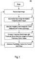
- FIG. 1is a flowchart illustrating a process of motion detection by decomposing images into frequency bands, in accordance with an embodiment of the present invention.
- FIG. 2is a block diagram illustrating a system for detecting motion by decomposing images into frequency bands, in accordance with an embodiment of the present invention.
- FIG. 3is a block diagram illustrating a system for detecting motion by decomposing images into frequency bands with a filter bank, in accordance with an embodiment of the present invention.
- FIG. 4is a flowchart illustrating a process of detecting motion by decomposing images into frequency bands using a Discrete Wavelet Transform, in accordance with an embodiment of the present invention.
- FIG. 5Ais a diagram illustrating frequency bands decomposed from an image by an embodiment in accordance with the present invention.
- FIG. 5Bis a diagram illustrating “x” and “y” component frequency bands decomposed from an image by an embodiment in accordance with the present invention.
- Embodiments in accordance with the present inventiondetect motion of a device moved across a surface for which detecting differences between features is difficult for conventional techniques. For example, embodiments of the present invention are able to filter out repetitive information that could interfere with accurately determining motion of an optical mouse moved across a surface if the repetitive information were not removed.
- FIG. 1is a flowchart illustrating a process 100 of detecting motion by breaking images into frequency bands. Steps of process 100 may be stored as instructions on a computer readable medium and executed on a general-purpose processor coupled thereto by a bus.
- an input imageis received.
- process 100is not so limited.
- the input imageis received from a CMOS sensor by a digital signal-processing component of an optical mouse.
- the present inventionis not so limited.
- the input imageis decomposed into multiple frequency band images.
- Each frequency band imagecontains a portion of the frequency information of the input image for a range of frequencies.
- the frequency band imageseach focus on a separate range of frequencies.
- the nature of the image decompositionmay not transform the input image into the ideal frequency band.
- the present inventionis not precluded from deliberately having overlap in the frequency band of two or more frequency band images.
- the minimum number of frequency band imagesis two.
- the maximumis not limited to any number.
- the number of frequency band images into which the input image is decomposedtypically affects the results of the final motion detection. The results typically improve with a greater number of frequency band images, at least if only a few are used. Therefore, the number of frequency band images into which the input image is decomposed may be selected to achieve desired results.
- the frequency band imagesare stored for use as reference band images in a later iteration of process 100 .
- the reference band imagesare used when processing the next input image received in step 110 .
- For each frequency band image produced in step 120there is a corresponding reference frequency band image that contains information from the input image for the same frequency band.
- step 130the frequency band images produced in step 120 are compared to reference frequency band images that were stored in step 125 of a previous iteration of process 100 .
- each frequency band imageis compared to the corresponding reference frequency band image having the same range of frequency information.
- the comparisonmay be a cross-correlation, but the present invention is not so limited.
- the imagesare separated by frequency, the images are processed in step 130 in the spatial domain (e.g., by cross-correlation), in some embodiments of the present invention.
- the inventionis not be limited to processing in the spatial domain.
- the processing in step 130is performed by other cross-correlation or non-cross-correlation methods in the frequency domain.
- the processing in step 130is performed by cross-correlation or non-cross-correlation methods in the spatial-frequency domain.
- the result of the comparison of step 130is a set of preliminary motion values.
- a motion valuecomprises a change in an “x” and a “y” coordinate. There may be one or more such motion values generated for each of the comparisons. However, the present invention is not limited to the motion values being changes in “x” and “y” coordinate values.
- a final motion valueis determined from the preliminary motion values.
- the preliminary motion valuesmay be summed with selected motion values given more weight than others, but the present invention is not so limited.
- greater or less emphasisis placed on a certain frequency range.
- a certain frequency rangemay contain information that is more or less useful in determining motion.
- the weightingis based on the direction of motion or based on surface properties such as fineness of the grain, in embodiments in accordance with the present invention. For example, a frequency band which works well or poorly for the x-direction may not work well or poorly for the y-direction. This may be due to a factor such as grain typically running in a certain direction on a desk or depend on how close the grains are spaced on the desk, although there may be other factors as well.
- the weighting for the changes in x-valuesis different from the weighting for the changes in y-values, in an embodiment in accordance with the present invention.
- the amount of weightingis predetermined in one embodiment; however, the present invention is not so limited.
- the weightingis dynamically determined during optical navigation by statistical processing of the previous images. The process 100 then returns to step 110 to process another input image.
- FIG. 2is a block diagram illustrating a system 200 for detecting motion by decomposing an image into frequency bands, in accordance with an embodiment of the present invention.
- the system 200includes an image sensor 210 .
- the image sensor 210is a CMOS sensor.
- the present inventionis not so limited.
- the image sensor 210sends images to the image decompose logic 220 .
- the image decompose logic 220may also be referred to as transform logic.
- the image decompose logic 220decomposes the images into frequency band images. Each frequency band image contains a portion of the frequency information of the input image for a range of frequencies.
- the image decompose logic 220sends the frequency band images to the reference image storage 225 for use when processing a later input image. Further, the image decompose logic 220 sends the frequency band images to the image comparison logic 230 .
- the image comparison logic 230performs a comparison of the frequency band images from the image decompose logic 220 with the reference images from the reference image storage 225 .
- the output of the image comparison logic 230is a motion value for each comparison. This results in a motion value for each frequency band. It will be understood that a motion value may be expressed in terms of, for example, an x-coordinate and a y-coordinate.
- the motion value logic 240inputs the motion values from the image comparison logic 230 and computes a final motion value therefrom.
- the final motion valueis output from the motion value logic.
- the image decompose logic 220is implemented with a filter bank.
- a filter bank embodimentwill be discussed in more detail with respect to FIG. 3 .
- the image decompose logic 220is capable of performing a Discrete Wavelet Transform.
- One embodiment of the present inventionis a redundant Discrete Wavelet Transform, in which down-sampling is not performed.
- embodiments of the present inventionare well-suited to all implementations of the Discrete Wavelet Transform and its variants.
- a Discrete Wavelet Transform embodimentwill be discussed in more detail with respect to FIG. 4 .
- the comparison logic 230is capable of performing a cross-correlation in one embodiment, but the present invention is not so limited. The present invention is not limited to processing in the spatial domain. In some embodiments in accordance with the invention, the comparison logic 230 is capable of performing other cross-correlation or non-cross-correlation methods in the frequency domain.
- the various logic in FIG. 2may be implemented in an application specific integrated circuit, in one embodiment.
- the image comparison logic 230 , the image decompose logic 220 , and the motion value logic 240are implemented by a processor executing instructions stored on a computer readable medium.
- FIG. 3is a flow diagram illustrating a system 300 for detecting motion by decomposing images into frequency bands, in accordance with an embodiment of the present invention.
- a filter bank 320is used to decompose the input image; however, the present invention is not limited to this technique for decomposing the input image.
- the system 300includes an image sensor 210 , which digitizes and sends an input image to the filter bank 320 .
- the image sensor 210is a CMOS sensor.
- the present inventionis not so limited.
- the filter banks 320are used decompose the input image into frequency band images in this embodiment.
- the filtersmay include a low-pass filter, a high-pass filter, and band-pass filters.
- the present inventionis not limited to any particular combination of filters. Thus, it is not required that there be a low-pass filter, or a band-pass filter, or a high-pass filter.
- This embodiment of the present inventionfilters the input image into at least two frequency band images (not depicted in FIG. 3 ) that contain different frequency information. There is no maximum number of frequency band images.
- FIG. 3depicts the filter banks 320 generating “n” frequency band images.
- the filter bank 320sends it output to cross-correlation logic 340 a - n .
- Each of the “n” frequency band imagesis compared to its corresponding reference frequency band image 330 a - n by performing a cross-correlation, in this embodiment.
- the cross correlationis performed on a subset of the pixels, in embodiments in accordance with the invention. Computation time is saved and the circuitry may be less complex by performing the cross-correlation on a subset of the pixels in the image.
- the results of the cross-correlationare motion values for each comparison.
- the motion valuesdescribe the difference in physical location between the current input image and the reference image.
- the motion valuesdescribe how far an optical mouse that captured the images has been moved by a user between the time the reference image and the current image were captured, in an optical mouse embodiment.
- a weighting or averaging function 350produces a final motion value, based on the preliminary motion values.
- the final motion valuecomprises a delta-x and a delta-y value.
- the delta-x and delta-y valuesare determined by weighting or averaging the preliminary delta-x and delta-y values.
- the present inventionis not so limited.
- an input imageis decomposed into frequency band images by recursively applying a Discrete Wavelet Transform.
- Discrete wavelet transformare known to those of ordinary skill in the art.
- quantization by thresholdingis not a required feature of the present invention.
- the frequency band imagesare cross-correlated with reference frequency band images to produce preliminary motion values.
- the preliminary motion valuesmay be weighted or averaged to produce final motion values, but the present invention is not so limited.
- FIG. 4is a flowchart illustrating a process of detecting motion by decomposing images into frequency bands with a redundant Discrete Wavelet Transform, in accordance with an embodiment of the present invention.
- a redundant Discrete Wavelet Transformis a Discrete Wavelet Transform performed without down-sampling.
- an input imageis received. The image may have been captured by a CMOS sensor, but the present invention is not so limited.
- Step 515is the beginning of a loop for performing a Discrete Wavelet Transform a pre-determined number of times.
- the loopis exited after the Discrete Wavelet Transform has been performed the pre-determined number of times.
- the Discrete Wavelet Transformcan be performed with many different sets of filter coefficients depending on the type of “wavelet” used.
- the type of wavelet useddetermines how the frequency bands are extracted from the image.
- Embodiments of the present inventionare well-suited to all sets of filter coefficients.
- embodiments of the present inventionare well-suited to all methods or algorithms of implementing the Discrete Wavelet Transform.
- a Discrete Wavelet Transformis performed on the input image or an image that was previously processed by a Discrete Wavelet Transform, depending on which iteration of the loop is being performed.
- Each additional Discrete Wavelet Transformdecomposes different frequency information from the input image.
- the same filter coefficientsmay be used. This greatly simplifies the process versus techniques that use different sets of filter coefficients to extract different frequency information. For example, pipelining is greatly facilitated and circuitry for executing the process is simpler.
- step 525the results of the Discrete Wavelet Transform from step 520 are stored for use as a future reference image.
- the reference imageis used when processing the next input image received in step 510 .
- step 530a cross-correlation is performed between the current Discrete Wavelet Transform output and a previously stored reference image from a previous input image.
- Step 535the result of the cross-correlation is analyzed.
- Step 540is a test to determine if the result of the current cross-correlation indicates motion. If it does not, then the process 500 returns to step 515 to perform another Discrete Wavelet Transform. If motion is indicated by the results of the cross-correlation, then the process 500 continues on to step 545 .
- Step 545is a test to determine if the result of step 535 indicates a significant deviation from the result of step 535 for the previous iteration of the loop. For example, the cross-correlation result of the third Discrete Wavelet Transform with its reference image is compared to the cross-correlation result of the second Discrete Wavelet Transform with its reference image. If the current cross-correlation result does not deviate significantly from the previous cross-correlation result, then the process 500 returns to step 515 . If there is not a significant deviation, there is not a need to update the motion values.
- the term “significant deviation” in this contextis meant to be flexible in that what is deemed significant may be determined for the particular application in which process 500 is practiced. If there is a significant deviation in the cross-correlation, then the process 500 goes on to step 550 to update the motion values.
- the third cross-correlation resultis significantly different from the second cross-correlation result, it may indicate that the second cross-correlation result was affected by repetitive information.
- the second cross-correlationmay have been affected because of the frequency content of its input images, given the nature of the surface for which the images were captured, and the velocity and direction of motion. Therefore, the results from the second cross-correlation are disregarded. If the result of the third Discrete Wavelet Transform is significantly different from the result of the second Discrete Wavelet Transform, then the results of the third Discrete Wavelet Transform are stored as the correct motion values in step 550 . In one embodiment, a register containing motion values is updated by overwriting previous motion values.
- step 550After updating the motion values in step 550 , the process returns to step 515 . If the Discrete Wavelet Transform is to be performed again, the process continues at step 520 . Otherwise, the process 500 goes to step 555 in which the motion values for this input image are output. Then, the process 500 goes to step 505 , in which a new input image is received. The process 500 then analyzes this input image, with the reference images stored from analyzing the previous input image serving as the reference images.
- FIG. 5Aillustrates an exemplary sequence of Discrete Wavelet Transforms and the frequency band images produced therefrom. It will be understood that the example of FIG. 5A is exemplary and that many other sequence of Discrete Wavelet Transforms are within the scope of the present invention.
- Each Discrete Wavelet Transformproduces two or more frequency band images. In this embodiment, each Discrete Wavelet Transform produces two frequency band images. In this embodiment of the present invention, one of the two frequency band images is further processed by an additional Discrete Wavelet Transform. Each successive application of the Discrete Wavelet Transform extracts a different band of frequency information.
- the first application of the Discrete Wavelet Transform 620 a to the input image 605produces a low-pass and a high-pass frequency band image 625 a and 625 b.
- the low pass frequency band image 625 ais further processed by the second Discrete Wavelet Transform 620 b , which produces another low-pass frequency band image 625 c and a band-pass frequency band image 625 d.
- the low-pass frequency band image 625 c and the band-pass frequency band image 625 dcomprise frequency bands within the low-pass pass frequency band image 625 a .
- the band-pass frequency band image 625 dis further processed by the third Discrete Wavelet Transform 620 c to produce further band-pass frequency band images 625 e and 625 f .
- This processcan continue further to extract further frequency information from the input image.
- the frequency band image that is processed by the next Discrete Wavelet Transformcan be tailored to extract the frequency information of interest.
- the high-pass frequency band image 625 bmay be processed.
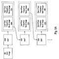
- FIG. 5Billustrates an exemplary sequence of Discrete Wavelet Transforms and “x” and “y” component frequency band images produced therefrom. It will be understood that the example of FIG.
- Each Discrete Wavelet Transformproduces four frequency band images, in this embodiment.
- the four frequency band imagesis further processed by four additional Discrete Wavelet Transforms.
- Each successive application of the Discrete Wavelet Transformextracts a different frequency band of “x” and “y” component frequency band information, in this embodiment.
- the first application of the Discrete Wavelet Transform 620 e to the input image 605produces image “a” 610 , image “b” 615 , image “c” 620 , and image “d” 625 .
- Image “a” 610has an “x” component low-pass frequency band and a “y” component low-pass frequency band.
- Image “b” 615has an “x” component low-pass frequency band and a “y” component high-pass frequency band.
- Image “c” 620has an “x” component high-pass frequency band and a “y” component low-pass frequency band.
- Image “d” 625has an “x” component high-pass frequency band and a “y” component high-pass frequency band.
- the four images ( 610 , 615 , 620 , 625 ) produced by the first Discrete Wavelet Transform 620 ehave “x” and “y” components with different frequency bands.
- each of the four images 610 , 615 , 620 , and 625are processed by an additional Discrete Wavelet Transform 620 f - 620 i , respectively.
- Each of these additional Discrete Wavelet Transformsproduces four images.
- the terms “low-pass” frequency band and “high-pass” frequency band in elements 630 - 645are relative to the input images 610 - 625 .
- Discrete Wavelet Transform 620 finputs image “a” 610 and produces image “a — 1” 630 having “x” and “y” component low-pass frequency bands.
- low-pass bandsare relative to the low-pass frequency band of image “a” 610 .
- image “a — 2” 631has a “y” component high-pass frequency band. It will be understood that this high-pass frequency band is relative to the low-pass frequency band of image “a” 610 .
- the process illustrated in FIG. 5Bextracts information for which the “x” and “y” component in a given image may have different frequency bands from each other.
- the “x” and “y” directionscan be processed in such a fashion to handle cases in which features do not repeat at the same interval along the “x” axis as they do along the “y” axis.
- the process in FIG. 5Bcan continue further to extract further frequency information from the input image.
- images 610 , 634 and 639could be selected for further processing, while other images are discarded. Therefore, a subset of images may be selected to work with from the images 610 - 625 from the initial DWT 620 e together with or independent of a subset of images 630 - 645 from the next level of DWT processing 620 f - i . To save on computation, if any image subset of 610 - 625 is selected their corresponding DWTs do not need to be performed (e.g., the group 620 f - 620 i DWT).
- DWT 620 eis not required since the frequency information decomposed by it is already present in image 610 .
- DWT 620 iis not required because the decomposed image bands resulting from it are not used in this example.
- Embodiments of the present inventionmay be stored as instructions on a computer readable medium and executed on a general-purpose processor coupled thereto by a bus.
- the present inventionis not limited to software implementation.
- Embodiments of the present inventionmay be implemented as an application specific integrated circuit. Some embodiments of the present invention are implemented by a combination of hardware and software.
Landscapes
- Engineering & Computer Science (AREA)
- Physics & Mathematics (AREA)
- Mathematical Physics (AREA)
- Multimedia (AREA)
- Computer Vision & Pattern Recognition (AREA)
- General Physics & Mathematics (AREA)
- Theoretical Computer Science (AREA)
- Image Analysis (AREA)
- Image Processing (AREA)
Abstract
Description
Claims (26)
Priority Applications (3)
| Application Number | Priority Date | Filing Date | Title |
|---|---|---|---|
| US10/670,894US7474767B2 (en) | 2003-09-24 | 2003-09-24 | Motion detection using multi-resolution image processing |
| DE102004033156ADE102004033156B4 (en) | 2003-09-24 | 2004-07-08 | Motion detection using multi-resolution image processing |
| GB0417986AGB2406456A (en) | 2003-09-24 | 2004-08-12 | Motion detection using multi-resolution image processing |
Applications Claiming Priority (1)
| Application Number | Priority Date | Filing Date | Title |
|---|---|---|---|
| US10/670,894US7474767B2 (en) | 2003-09-24 | 2003-09-24 | Motion detection using multi-resolution image processing |
Publications (2)
| Publication Number | Publication Date |
|---|---|
| US20050063598A1 US20050063598A1 (en) | 2005-03-24 |
| US7474767B2true US7474767B2 (en) | 2009-01-06 |
Family
ID=33030245
Family Applications (1)
| Application Number | Title | Priority Date | Filing Date |
|---|---|---|---|
| US10/670,894Active2026-04-25US7474767B2 (en) | 2003-09-24 | 2003-09-24 | Motion detection using multi-resolution image processing |
Country Status (3)
| Country | Link |
|---|---|
| US (1) | US7474767B2 (en) |
| DE (1) | DE102004033156B4 (en) |
| GB (1) | GB2406456A (en) |
Cited By (22)
| Publication number | Priority date | Publication date | Assignee | Title |
|---|---|---|---|---|
| US20100296140A1 (en)* | 2009-05-20 | 2010-11-25 | Dacuda Ag | Handheld scanner with high image quality |
| US20100296133A1 (en)* | 2009-05-20 | 2010-11-25 | Dacuda Ag | Mode switching in a handheld scanner |
| US20100295868A1 (en)* | 2009-05-20 | 2010-11-25 | Dacuda Ag | Image processing for handheld scanner |
| US20100296129A1 (en)* | 2009-05-20 | 2010-11-25 | Dacuda Ag | Automatic sizing of images acquired by a handheld scanner |
| US20100296137A1 (en)* | 2009-05-20 | 2010-11-25 | Dacuda Ag | Continuous scanning with a handheld scanner |
| US20110038508A1 (en)* | 2009-08-17 | 2011-02-17 | Avago Technologies Ecbu Ip (Singapore) Pte. Ltd. | System and method for performing optical navigation using portions of captured frames of image data |
| US20110050573A1 (en)* | 2009-08-25 | 2011-03-03 | Stavely Donald J | Tracking motion of mouse on smooth surfaces |
| US20110234815A1 (en)* | 2010-03-25 | 2011-09-29 | Dacuda Ag | Synchronization of navigation and image information for handheld scanner |
| US20130022235A1 (en)* | 2011-07-22 | 2013-01-24 | Microsoft Corporation | Interactive secret sharing |
| TWI549096B (en)* | 2011-05-13 | 2016-09-11 | 華晶科技股份有限公司 | Image processing device and processing method thereof |
| TWI602152B (en)* | 2013-02-06 | 2017-10-11 | 聚晶半導體股份有限公司 | Image capturing device and image processing method thereof |
| US10142522B2 (en) | 2013-12-03 | 2018-11-27 | Ml Netherlands C.V. | User feedback for real-time checking and improving quality of scanned image |
| US10298898B2 (en) | 2013-08-31 | 2019-05-21 | Ml Netherlands C.V. | User feedback for real-time checking and improving quality of scanned image |
| US10410321B2 (en) | 2014-01-07 | 2019-09-10 | MN Netherlands C.V. | Dynamic updating of a composite image |
| US10484561B2 (en) | 2014-05-12 | 2019-11-19 | Ml Netherlands C.V. | Method and apparatus for scanning and printing a 3D object |
| US10708491B2 (en) | 2014-01-07 | 2020-07-07 | Ml Netherlands C.V. | Adaptive camera control for reducing motion blur during real-time image capture |
| US11111542B2 (en) | 2016-02-06 | 2021-09-07 | University Health Network | Method for identifying high-risk AML patients |
| US11843868B2 (en) | 2021-07-13 | 2023-12-12 | SK Hynix Inc. | Electronic apparatus based on multiple exposure image and operating method thereof |
| WO2024155336A1 (en)* | 2023-01-19 | 2024-07-25 | SimpliSafe, Inc. | Multi resolution motion detection |
| US12100181B2 (en) | 2020-05-11 | 2024-09-24 | Magic Leap, Inc. | Computationally efficient method for computing a composite representation of a 3D environment |
| US12169940B2 (en) | 2023-01-30 | 2024-12-17 | SimpliSafe, Inc. | Methods and apparatus for motion detection |
| US12211283B2 (en) | 2023-01-30 | 2025-01-28 | SimpliSafe, Inc. | Methods and apparatus for detecting pets |
Families Citing this family (10)
| Publication number | Priority date | Publication date | Assignee | Title |
|---|---|---|---|---|
| KR100921817B1 (en)* | 2008-01-31 | 2009-10-16 | 주식회사 애트랩 | Image sensor and optical pointing device using same |
| EP1684506A4 (en)* | 2003-11-11 | 2008-06-04 | Seiko Epson Corp | IMAGE PROCESSING DEVICE, IMAGE PROCESSING METHOD, PROGRAM THEREOF, AND RECORDING MEDIUM |
| GB2443581B (en)* | 2005-11-07 | 2010-06-09 | Sony Corp | Recording apparatus, method, and program |
| JP4529874B2 (en) | 2005-11-07 | 2010-08-25 | ソニー株式会社 | Recording / reproducing apparatus, recording / reproducing method, recording apparatus, recording method, reproducing apparatus, reproducing method, and program |
| JP5057675B2 (en)* | 2006-03-03 | 2012-10-24 | オリンパスメディカルシステムズ株式会社 | Living body observation device |
| JP5079552B2 (en)* | 2008-03-13 | 2012-11-21 | オリンパス株式会社 | Image processing apparatus, imaging apparatus, and image processing method |
| CN101592848B (en)* | 2008-05-28 | 2011-04-20 | 艾勒博科技股份有限公司 | Optical indicator device |
| US20100020016A1 (en)* | 2008-07-25 | 2010-01-28 | Monahan Michael J | Computer Mouse |
| US8744522B2 (en)* | 2009-10-21 | 2014-06-03 | Xerox Corporation | Portable security system built into cell phones |
| CN102810027B (en)* | 2011-06-03 | 2015-08-19 | 友碁科技股份有限公司 | Optical input device and control method |
Citations (18)
| Publication number | Priority date | Publication date | Assignee | Title |
|---|---|---|---|---|
| EP0446001A2 (en) | 1990-03-06 | 1991-09-11 | Victor Company Of Japan, Ltd. | Motion vector detection circuit used in hierarchical processing of moving picture signal |
| US5477272A (en) | 1993-07-22 | 1995-12-19 | Gte Laboratories Incorporated | Variable-block size multi-resolution motion estimation scheme for pyramid coding |
| US5557341A (en)* | 1991-04-12 | 1996-09-17 | Dv Sweden Ab | Iterative method for estimating motion content in video signals using successively reduced block size |
| US5583580A (en) | 1994-10-08 | 1996-12-10 | Daewoo Electronics Co., Ltd. | Method and apparatus for detecting motion vectors based on hierarchical motion estimation |
| GB2307135A (en) | 1995-11-08 | 1997-05-14 | Daewoo Electronics Co Ltd | Determining motion vector of search block using motion vectors of neighbouring blocks |
| GB2327313A (en) | 1997-06-30 | 1999-01-20 | Daewoo Electronics Co Ltd | Motion vector detection in a wavelet transformed video signal |
| US6141448A (en)* | 1997-04-21 | 2000-10-31 | Hewlett-Packard | Low-complexity error-resilient coder using a block-based standard |
| US6259613B1 (en)* | 1998-05-22 | 2001-07-10 | Samsung Electronics Co., Ltd. | Power factor correction (PFC) circuit |
| US20020057736A1 (en)* | 1997-08-28 | 2002-05-16 | Hideyuki Fuji | Image coding apparatus and method |
| US20020186772A1 (en)* | 2001-06-08 | 2002-12-12 | Xin Li | Wavelet domain motion compensation system |
| WO2003001814A1 (en) | 2001-06-26 | 2003-01-03 | Koninklijke Philips Electronics N.V. | Video coding method |
| US20030063672A1 (en)* | 1999-12-09 | 2003-04-03 | Nathalie Laurent-Chatenet | Method for estimating the motion between two digital images with management of mesh overturning and corresponding coding method |
| US20040136490A1 (en)* | 2002-07-23 | 2004-07-15 | Edic Peter Michael | Method and apparatus for correcting motion in image reconstruction |
| US6795578B1 (en)* | 1999-09-29 | 2004-09-21 | Canon Kabushiki Kaisha | Image processing apparatus and method, and storage medium |
| US6931145B1 (en)* | 1999-11-16 | 2005-08-16 | Advanced Telecommunications Research Institute International | Method and apparatus for measuring motion of an object surface by multi-resolution analysis using a mesh model |
| US6937773B1 (en)* | 1999-10-20 | 2005-08-30 | Canon Kabushiki Kaisha | Image encoding method and apparatus |
| US7068851B1 (en)* | 1999-12-10 | 2006-06-27 | Ricoh Co., Ltd. | Multiscale sharpening and smoothing with wavelets |
| US7099512B2 (en)* | 2002-04-09 | 2006-08-29 | Stmicroelectronics S.R.L. | Process and device for global motion estimation in a sequence of images and a computer program product therefor |
- 2003
- 2003-09-24USUS10/670,894patent/US7474767B2/enactiveActive
- 2004
- 2004-07-08DEDE102004033156Apatent/DE102004033156B4/ennot_activeExpired - Fee Related
- 2004-08-12GBGB0417986Apatent/GB2406456A/ennot_activeWithdrawn
Patent Citations (19)
| Publication number | Priority date | Publication date | Assignee | Title |
|---|---|---|---|---|
| EP0446001A2 (en) | 1990-03-06 | 1991-09-11 | Victor Company Of Japan, Ltd. | Motion vector detection circuit used in hierarchical processing of moving picture signal |
| US5557341A (en)* | 1991-04-12 | 1996-09-17 | Dv Sweden Ab | Iterative method for estimating motion content in video signals using successively reduced block size |
| US5477272A (en) | 1993-07-22 | 1995-12-19 | Gte Laboratories Incorporated | Variable-block size multi-resolution motion estimation scheme for pyramid coding |
| US5583580A (en) | 1994-10-08 | 1996-12-10 | Daewoo Electronics Co., Ltd. | Method and apparatus for detecting motion vectors based on hierarchical motion estimation |
| GB2307135A (en) | 1995-11-08 | 1997-05-14 | Daewoo Electronics Co Ltd | Determining motion vector of search block using motion vectors of neighbouring blocks |
| US6141448A (en)* | 1997-04-21 | 2000-10-31 | Hewlett-Packard | Low-complexity error-resilient coder using a block-based standard |
| GB2327313A (en) | 1997-06-30 | 1999-01-20 | Daewoo Electronics Co Ltd | Motion vector detection in a wavelet transformed video signal |
| US20020057736A1 (en)* | 1997-08-28 | 2002-05-16 | Hideyuki Fuji | Image coding apparatus and method |
| US6259613B1 (en)* | 1998-05-22 | 2001-07-10 | Samsung Electronics Co., Ltd. | Power factor correction (PFC) circuit |
| US6795578B1 (en)* | 1999-09-29 | 2004-09-21 | Canon Kabushiki Kaisha | Image processing apparatus and method, and storage medium |
| US6937773B1 (en)* | 1999-10-20 | 2005-08-30 | Canon Kabushiki Kaisha | Image encoding method and apparatus |
| US6931145B1 (en)* | 1999-11-16 | 2005-08-16 | Advanced Telecommunications Research Institute International | Method and apparatus for measuring motion of an object surface by multi-resolution analysis using a mesh model |
| US20030063672A1 (en)* | 1999-12-09 | 2003-04-03 | Nathalie Laurent-Chatenet | Method for estimating the motion between two digital images with management of mesh overturning and corresponding coding method |
| US7068851B1 (en)* | 1999-12-10 | 2006-06-27 | Ricoh Co., Ltd. | Multiscale sharpening and smoothing with wavelets |
| US20020186772A1 (en)* | 2001-06-08 | 2002-12-12 | Xin Li | Wavelet domain motion compensation system |
| WO2003001814A1 (en) | 2001-06-26 | 2003-01-03 | Koninklijke Philips Electronics N.V. | Video coding method |
| US20050031037A1 (en)* | 2001-06-26 | 2005-02-10 | Paul Carrasco | Video coding method |
| US7099512B2 (en)* | 2002-04-09 | 2006-08-29 | Stmicroelectronics S.R.L. | Process and device for global motion estimation in a sequence of images and a computer program product therefor |
| US20040136490A1 (en)* | 2002-07-23 | 2004-07-15 | Edic Peter Michael | Method and apparatus for correcting motion in image reconstruction |
Non-Patent Citations (5)
| Title |
|---|
| DeVore et al. ("Motion Estimation with the Redundant Wavelet Transform," IEEE Int'l Workshop on Digital and Computational Video, Nov. 2002, pp. 53-58).* |
| Friend et al. ("Real-Time Wavelet Based Target Tracking," SPIE vol. 3517, Nov. 1998, pp. 349-355).* |
| Rosenfeld and Kak: Digital Picture Processing, 2nd ed., vol. 2, 1982, pp. 44-46.* |
| Toyokura et al. ("Wavelet Coefficients Motion Compensation for Image Sequence Encoding," IEEE Conf. Circuits and Systems, Nov. 24-27, 1998, pp. 53-56).* |
| Zafar et al. ("Multiscale Video Representation Using Multiresolution Motion Compensation and Wavelet Decomposition," IEEE J. Selected Areas in Communications, V. 11, No. 1, Jan. 1993, pp. 24-35).* |
Cited By (43)
| Publication number | Priority date | Publication date | Assignee | Title |
|---|---|---|---|---|
| US8441696B2 (en) | 2009-05-20 | 2013-05-14 | Dacuda Ag | Continuous scanning with a handheld scanner |
| US20100296133A1 (en)* | 2009-05-20 | 2010-11-25 | Dacuda Ag | Mode switching in a handheld scanner |
| US20100295868A1 (en)* | 2009-05-20 | 2010-11-25 | Dacuda Ag | Image processing for handheld scanner |
| US20100296129A1 (en)* | 2009-05-20 | 2010-11-25 | Dacuda Ag | Automatic sizing of images acquired by a handheld scanner |
| US20100296137A1 (en)* | 2009-05-20 | 2010-11-25 | Dacuda Ag | Continuous scanning with a handheld scanner |
| US20100296131A1 (en)* | 2009-05-20 | 2010-11-25 | Dacuda Ag | Real-time display of images acquired by a handheld scanner |
| US20100296140A1 (en)* | 2009-05-20 | 2010-11-25 | Dacuda Ag | Handheld scanner with high image quality |
| US9300834B2 (en) | 2009-05-20 | 2016-03-29 | Dacuda Ag | Image processing for handheld scanner |
| US8723885B2 (en) | 2009-05-20 | 2014-05-13 | Dacuda Ag | Real-time display of images acquired by a handheld scanner |
| US10225428B2 (en) | 2009-05-20 | 2019-03-05 | Ml Netherlands C.V. | Image processing for handheld scanner |
| US8582182B2 (en) | 2009-05-20 | 2013-11-12 | Dacuda Ag | Automatic sizing of images acquired by a handheld scanner |
| US8441695B2 (en) | 2009-05-20 | 2013-05-14 | Dacuda Ag | Handheld scanner with high image quality |
| US8611584B2 (en) | 2009-08-17 | 2013-12-17 | Avago Technologies General Ip (Singapore) Pte. Ltd. | System and method for performing optical navigation using portions of captured frames of image data |
| US20110038508A1 (en)* | 2009-08-17 | 2011-02-17 | Avago Technologies Ecbu Ip (Singapore) Pte. Ltd. | System and method for performing optical navigation using portions of captured frames of image data |
| US8525777B2 (en) | 2009-08-25 | 2013-09-03 | Microsoft Corporation | Tracking motion of mouse on smooth surfaces |
| US20110050573A1 (en)* | 2009-08-25 | 2011-03-03 | Stavely Donald J | Tracking motion of mouse on smooth surfaces |
| US8339467B2 (en) | 2010-03-25 | 2012-12-25 | Dacuda Ag | Synchronization of navigation and image information for handheld scanner |
| US20110234815A1 (en)* | 2010-03-25 | 2011-09-29 | Dacuda Ag | Synchronization of navigation and image information for handheld scanner |
| TWI549096B (en)* | 2011-05-13 | 2016-09-11 | 華晶科技股份有限公司 | Image processing device and processing method thereof |
| US20130022235A1 (en)* | 2011-07-22 | 2013-01-24 | Microsoft Corporation | Interactive secret sharing |
| US8885878B2 (en)* | 2011-07-22 | 2014-11-11 | Microsoft Corporation | Interactive secret sharing |
| TWI602152B (en)* | 2013-02-06 | 2017-10-11 | 聚晶半導體股份有限公司 | Image capturing device and image processing method thereof |
| US10298898B2 (en) | 2013-08-31 | 2019-05-21 | Ml Netherlands C.V. | User feedback for real-time checking and improving quality of scanned image |
| US10841551B2 (en) | 2013-08-31 | 2020-11-17 | Ml Netherlands C.V. | User feedback for real-time checking and improving quality of scanned image |
| US11563926B2 (en) | 2013-08-31 | 2023-01-24 | Magic Leap, Inc. | User feedback for real-time checking and improving quality of scanned image |
| US10375279B2 (en) | 2013-12-03 | 2019-08-06 | Ml Netherlands C.V. | User feedback for real-time checking and improving quality of scanned image |
| US10455128B2 (en) | 2013-12-03 | 2019-10-22 | Ml Netherlands C.V. | User feedback for real-time checking and improving quality of scanned image |
| US11798130B2 (en) | 2013-12-03 | 2023-10-24 | Magic Leap, Inc. | User feedback for real-time checking and improving quality of scanned image |
| US11115565B2 (en) | 2013-12-03 | 2021-09-07 | Ml Netherlands C.V. | User feedback for real-time checking and improving quality of scanned image |
| US10142522B2 (en) | 2013-12-03 | 2018-11-27 | Ml Netherlands C.V. | User feedback for real-time checking and improving quality of scanned image |
| US11516383B2 (en) | 2014-01-07 | 2022-11-29 | Magic Leap, Inc. | Adaptive camera control for reducing motion blur during real-time image capture |
| US10410321B2 (en) | 2014-01-07 | 2019-09-10 | MN Netherlands C.V. | Dynamic updating of a composite image |
| US10708491B2 (en) | 2014-01-07 | 2020-07-07 | Ml Netherlands C.V. | Adaptive camera control for reducing motion blur during real-time image capture |
| US11315217B2 (en) | 2014-01-07 | 2022-04-26 | Ml Netherlands C.V. | Dynamic updating of a composite image |
| US11245806B2 (en) | 2014-05-12 | 2022-02-08 | Ml Netherlands C.V. | Method and apparatus for scanning and printing a 3D object |
| US10484561B2 (en) | 2014-05-12 | 2019-11-19 | Ml Netherlands C.V. | Method and apparatus for scanning and printing a 3D object |
| US12309333B2 (en) | 2014-05-12 | 2025-05-20 | Magic Leap, Inc. | Method and apparatus for scanning and printing a 3D object |
| US11111542B2 (en) | 2016-02-06 | 2021-09-07 | University Health Network | Method for identifying high-risk AML patients |
| US12100181B2 (en) | 2020-05-11 | 2024-09-24 | Magic Leap, Inc. | Computationally efficient method for computing a composite representation of a 3D environment |
| US11843868B2 (en) | 2021-07-13 | 2023-12-12 | SK Hynix Inc. | Electronic apparatus based on multiple exposure image and operating method thereof |
| WO2024155336A1 (en)* | 2023-01-19 | 2024-07-25 | SimpliSafe, Inc. | Multi resolution motion detection |
| US12169940B2 (en) | 2023-01-30 | 2024-12-17 | SimpliSafe, Inc. | Methods and apparatus for motion detection |
| US12211283B2 (en) | 2023-01-30 | 2025-01-28 | SimpliSafe, Inc. | Methods and apparatus for detecting pets |
Also Published As
| Publication number | Publication date |
|---|---|
| DE102004033156A1 (en) | 2005-06-09 |
| US20050063598A1 (en) | 2005-03-24 |
| DE102004033156B4 (en) | 2007-10-04 |
| GB0417986D0 (en) | 2004-09-15 |
| GB2406456A (en) | 2005-03-30 |
Similar Documents
| Publication | Publication Date | Title |
|---|---|---|
| US7474767B2 (en) | Motion detection using multi-resolution image processing | |
| Balster et al. | Combined spatial and temporal domain wavelet shrinkage algorithm for video denoising | |
| Panjwani et al. | Markov random field models for unsupervised segmentation of textured color images | |
| Cantoni et al. | Vanishing point detection: representation analysis and new approaches | |
| D'Orazio et al. | A new algorithm for ball recognition using circle Hough transform and neural classifier | |
| Protter et al. | Image sequence denoising via sparse and redundant representations | |
| Bretzner et al. | Feature tracking with automatic selection of spatial scales | |
| US7813581B1 (en) | Bayesian methods for noise reduction in image processing | |
| JP4686663B2 (en) | Pedestrian tracking method and pedestrian tracking device | |
| Kobylin et al. | Comparison of standard image edge detection techniques and of method based on wavelet transform | |
| US20150253863A1 (en) | Image Processor Comprising Gesture Recognition System with Static Hand Pose Recognition Based on First and Second Sets of Features | |
| JP6727642B2 (en) | Focus correction processing method by learning algorithm | |
| US7356185B2 (en) | Preparation of a digital image with subsequent edge detection | |
| Rahmdel et al. | A Review of Hough Transform and Line Segment Detection Approaches. | |
| Vishwakarma et al. | Human activity recognition using gabor wavelet transform and ridgelet transform | |
| Khmag et al. | Additive noise reduction in natural images using second‐generation wavelet transform hidden Markov models | |
| Nikodémusz-Székely et al. | Image recognition problems of fingerprint identification | |
| Babaeian et al. | Mean shift-based object tracking with multiple features | |
| Paraschiv-Ionescu et al. | Source separation in strong noisy mixtures: a study of wavelet de-noising pre-processing | |
| Gastounioti et al. | Affine optical flow combined with multiscale image analysis for motion estimation of the arterial wall from B-mode ultrasound | |
| Lee et al. | Fingerprint recognition algorithm development using directional information in wavelet transform domain | |
| Marteau et al. | Down-sampling coupled to elastic kernel machines for efficient recognition of isolated gestures | |
| Wei et al. | On active camera control and camera motion recovery with foveate wavelet transform | |
| Kesrarat et al. | Noise resistance territorial intensity-based optical flow using inverse confidential technique on bilateral function | |
| Saleem et al. | Novel edge detection |
Legal Events
| Date | Code | Title | Description |
|---|---|---|---|
| AS | Assignment | Owner name:AGILENT TECHNOLOGIES, INC., COLORADO Free format text:ASSIGNMENT OF ASSIGNORS INTEREST;ASSIGNORS:SEN, LIEW TONG;WEI, HO TATT;REEL/FRAME:014331/0010;SIGNING DATES FROM 20030923 TO 20030925 | |
| AS | Assignment | Owner name:AVAGO TECHNOLOGIES GENERAL IP PTE. LTD.,SINGAPORE Free format text:ASSIGNMENT OF ASSIGNORS INTEREST;ASSIGNOR:AGILENT TECHNOLOGIES, INC.;REEL/FRAME:017206/0666 Effective date:20051201 Owner name:AVAGO TECHNOLOGIES GENERAL IP PTE. LTD., SINGAPORE Free format text:ASSIGNMENT OF ASSIGNORS INTEREST;ASSIGNOR:AGILENT TECHNOLOGIES, INC.;REEL/FRAME:017206/0666 Effective date:20051201 | |
| AS | Assignment | Owner name:AVAGO TECHNOLOGIES ECBU IP (SINGAPORE) PTE. LTD., SINGAPORE Free format text:ASSIGNMENT OF ASSIGNORS INTEREST;ASSIGNOR:AVAGO TECHNOLOGIES GENERAL IP (SINGAPORE) PTE. LTD.;REEL/FRAME:017675/0518 Effective date:20060127 Owner name:AVAGO TECHNOLOGIES ECBU IP (SINGAPORE) PTE. LTD.,S Free format text:ASSIGNMENT OF ASSIGNORS INTEREST;ASSIGNOR:AVAGO TECHNOLOGIES GENERAL IP (SINGAPORE) PTE. LTD.;REEL/FRAME:017675/0518 Effective date:20060127 Owner name:AVAGO TECHNOLOGIES ECBU IP (SINGAPORE) PTE. LTD., Free format text:ASSIGNMENT OF ASSIGNORS INTEREST;ASSIGNOR:AVAGO TECHNOLOGIES GENERAL IP (SINGAPORE) PTE. LTD.;REEL/FRAME:017675/0518 Effective date:20060127 | |
| STCF | Information on status: patent grant | Free format text:PATENTED CASE | |
| CC | Certificate of correction | ||
| FPAY | Fee payment | Year of fee payment:4 | |
| AS | Assignment | Owner name:AVAGO TECHNOLOGIES GENERAL IP (SINGAPORE) PTE. LTD Free format text:MERGER;ASSIGNOR:AVAGO TECHNOLOGIES ECBU IP (SINGAPORE) PTE. LTD.;REEL/FRAME:030369/0528 Effective date:20121030 | |
| AS | Assignment | Owner name:DEUTSCHE BANK AG NEW YORK BRANCH, AS COLLATERAL AGENT, NEW YORK Free format text:PATENT SECURITY AGREEMENT;ASSIGNOR:AVAGO TECHNOLOGIES GENERAL IP (SINGAPORE) PTE. LTD.;REEL/FRAME:032851/0001 Effective date:20140506 Owner name:DEUTSCHE BANK AG NEW YORK BRANCH, AS COLLATERAL AG Free format text:PATENT SECURITY AGREEMENT;ASSIGNOR:AVAGO TECHNOLOGIES GENERAL IP (SINGAPORE) PTE. LTD.;REEL/FRAME:032851/0001 Effective date:20140506 | |
| AS | Assignment | Owner name:AVAGO TECHNOLOGIES GENERAL IP (SINGAPORE) PTE. LTD., SINGAPORE Free format text:TERMINATION AND RELEASE OF SECURITY INTEREST IN PATENT RIGHTS (RELEASES RF 032851-0001);ASSIGNOR:DEUTSCHE BANK AG NEW YORK BRANCH, AS COLLATERAL AGENT;REEL/FRAME:037689/0001 Effective date:20160201 Owner name:AVAGO TECHNOLOGIES GENERAL IP (SINGAPORE) PTE. LTD Free format text:TERMINATION AND RELEASE OF SECURITY INTEREST IN PATENT RIGHTS (RELEASES RF 032851-0001);ASSIGNOR:DEUTSCHE BANK AG NEW YORK BRANCH, AS COLLATERAL AGENT;REEL/FRAME:037689/0001 Effective date:20160201 | |
| AS | Assignment | Owner name:BANK OF AMERICA, N.A., AS COLLATERAL AGENT, NORTH CAROLINA Free format text:PATENT SECURITY AGREEMENT;ASSIGNOR:AVAGO TECHNOLOGIES GENERAL IP (SINGAPORE) PTE. LTD.;REEL/FRAME:037808/0001 Effective date:20160201 Owner name:BANK OF AMERICA, N.A., AS COLLATERAL AGENT, NORTH Free format text:PATENT SECURITY AGREEMENT;ASSIGNOR:AVAGO TECHNOLOGIES GENERAL IP (SINGAPORE) PTE. LTD.;REEL/FRAME:037808/0001 Effective date:20160201 | |
| AS | Assignment | Owner name:AVAGO TECHNOLOGIES GENERAL IP (SINGAPORE) PTE. LTD Free format text:CORRECTIVE ASSIGNMENT TO CORRECT THE ASSIGNEE NAME PREVIOUSLY RECORDED AT REEL: 017206 FRAME: 0666. ASSIGNOR(S) HEREBY CONFIRMS THE ASSIGNMENT;ASSIGNOR:AGILENT TECHNOLOGIES, INC.;REEL/FRAME:038632/0662 Effective date:20051201 | |
| FPAY | Fee payment | Year of fee payment:8 | |
| AS | Assignment | Owner name:PIXART IMAGING INC., TAIWAN Free format text:ASSIGNMENT OF ASSIGNORS INTEREST;ASSIGNOR:AVAGO TECHNOLOGIES GENERAL IP (SINGAPORE) PTE. LTD.;REEL/FRAME:039788/0572 Effective date:20160805 | |
| AS | Assignment | Owner name:AVAGO TECHNOLOGIES GENERAL IP (SINGAPORE) PTE. LTD., SINGAPORE Free format text:TERMINATION AND RELEASE OF SECURITY INTEREST IN PATENTS;ASSIGNOR:BANK OF AMERICA, N.A., AS COLLATERAL AGENT;REEL/FRAME:039862/0129 Effective date:20160826 Owner name:AVAGO TECHNOLOGIES GENERAL IP (SINGAPORE) PTE. LTD Free format text:TERMINATION AND RELEASE OF SECURITY INTEREST IN PATENTS;ASSIGNOR:BANK OF AMERICA, N.A., AS COLLATERAL AGENT;REEL/FRAME:039862/0129 Effective date:20160826 | |
| AS | Assignment | Owner name:AVAGO TECHNOLOGIES GENERAL IP (SINGAPORE) PTE. LTD., SINGAPORE Free format text:TERMINATION AND RELEASE OF SECURITY INTEREST IN PATENTS;ASSIGNOR:BANK OF AMERICA, N.A., AS COLLATERAL AGENT;REEL/FRAME:041710/0001 Effective date:20170119 Owner name:AVAGO TECHNOLOGIES GENERAL IP (SINGAPORE) PTE. LTD Free format text:TERMINATION AND RELEASE OF SECURITY INTEREST IN PATENTS;ASSIGNOR:BANK OF AMERICA, N.A., AS COLLATERAL AGENT;REEL/FRAME:041710/0001 Effective date:20170119 | |
| MAFP | Maintenance fee payment | Free format text:PAYMENT OF MAINTENANCE FEE, 12TH YEAR, LARGE ENTITY (ORIGINAL EVENT CODE: M1553); ENTITY STATUS OF PATENT OWNER: LARGE ENTITY Year of fee payment:12 |