US7474592B2 - Secure operation of a versatile device based on whether an authenticated user continues to wear the versatile device after initiating its use - Google Patents
Secure operation of a versatile device based on whether an authenticated user continues to wear the versatile device after initiating its useDownload PDFInfo
- Publication number
- US7474592B2 US7474592B2US10/011,925US1192501AUS7474592B2US 7474592 B2US7474592 B2US 7474592B2US 1192501 AUS1192501 AUS 1192501AUS 7474592 B2US7474592 B2US 7474592B2
- Authority
- US
- United States
- Prior art keywords
- data channel
- versatile device
- wristwatch
- authenticated user
- contacting electrical
- Prior art date
- Legal status (The legal status is an assumption and is not a legal conclusion. Google has not performed a legal analysis and makes no representation as to the accuracy of the status listed.)
- Expired - Fee Related, expires
Links
- 230000000977initiatory effectEffects0.000titleclaimsabstractdescription10
- 238000000034methodMethods0.000claimsabstractdescription25
- 238000010200validation analysisMethods0.000claimsabstractdescription21
- 230000007246mechanismEffects0.000claimsabstractdescription20
- 230000003287optical effectEffects0.000claimsdescription16
- 230000008878couplingEffects0.000claimsdescription14
- 238000010168coupling processMethods0.000claimsdescription14
- 238000005859coupling reactionMethods0.000claimsdescription14
- 230000001939inductive effectEffects0.000claimsdescription10
- 230000005540biological transmissionEffects0.000claimsdescription9
- 238000012544monitoring processMethods0.000claimsdescription7
- 230000000737periodic effectEffects0.000claimsdescription6
- 230000008569processEffects0.000claimsdescription5
- 239000013307optical fiberSubstances0.000claimsdescription2
- 230000003993interactionEffects0.000description5
- 238000005259measurementMethods0.000description4
- 230000002159abnormal effectEffects0.000description3
- 239000002184metalSubstances0.000description3
- 238000012986modificationMethods0.000description3
- 230000004048modificationEffects0.000description3
- 210000000707wristAnatomy0.000description3
- 230000008901benefitEffects0.000description2
- 238000010586diagramMethods0.000description2
- 238000004519manufacturing processMethods0.000description2
- 239000000463materialSubstances0.000description2
- 238000012546transferMethods0.000description2
- 230000003466anti-cipated effectEffects0.000description1
- 238000013459approachMethods0.000description1
- 238000013475authorizationMethods0.000description1
- 239000003990capacitorSubstances0.000description1
- 230000008859changeEffects0.000description1
- 238000004891communicationMethods0.000description1
- 238000013500data storageMethods0.000description1
- 238000013461designMethods0.000description1
- 238000001514detection methodMethods0.000description1
- 230000006870functionEffects0.000description1
- 238000011423initialization methodMethods0.000description1
- 230000010354integrationEffects0.000description1
- 238000000691measurement methodMethods0.000description1
- 230000001681protective effectEffects0.000description1
- 210000001525retinaAnatomy0.000description1
- 239000013589supplementSubstances0.000description1
- 238000012795verificationMethods0.000description1
Images


Classifications
- G—PHYSICS
- G04—HOROLOGY
- G04G—ELECTRONIC TIME-PIECES
- G04G21/00—Input or output devices integrated in time-pieces
- G04G21/04—Input or output devices integrated in time-pieces using radio waves
- G—PHYSICS
- G04—HOROLOGY
- G04G—ELECTRONIC TIME-PIECES
- G04G17/00—Structural details; Housings
- G04G17/08—Housings
- G04G17/083—Watches distributed over several housings
- G—PHYSICS
- G04—HOROLOGY
- G04G—ELECTRONIC TIME-PIECES
- G04G21/00—Input or output devices integrated in time-pieces
- G04G21/02—Detectors of external physical values, e.g. temperature
- G—PHYSICS
- G07—CHECKING-DEVICES
- G07C—TIME OR ATTENDANCE REGISTERS; REGISTERING OR INDICATING THE WORKING OF MACHINES; GENERATING RANDOM NUMBERS; VOTING OR LOTTERY APPARATUS; ARRANGEMENTS, SYSTEMS OR APPARATUS FOR CHECKING NOT PROVIDED FOR ELSEWHERE
- G07C9/00—Individual registration on entry or exit
- G07C9/30—Individual registration on entry or exit not involving the use of a pass
- G07C9/32—Individual registration on entry or exit not involving the use of a pass in combination with an identity check
- G07C9/37—Individual registration on entry or exit not involving the use of a pass in combination with an identity check using biometric data, e.g. fingerprints, iris scans or voice recognition
- H—ELECTRICITY
- H04—ELECTRIC COMMUNICATION TECHNIQUE
- H04W—WIRELESS COMMUNICATION NETWORKS
- H04W12/00—Security arrangements; Authentication; Protecting privacy or anonymity
- H04W12/06—Authentication
- H04W12/068—Authentication using credential vaults, e.g. password manager applications or one time password [OTP] applications
- H—ELECTRICITY
- H04—ELECTRIC COMMUNICATION TECHNIQUE
- H04W—WIRELESS COMMUNICATION NETWORKS
- H04W12/00—Security arrangements; Authentication; Protecting privacy or anonymity
- H04W12/08—Access security
- H04W12/082—Access security using revocation of authorisation
- H—ELECTRICITY
- H04—ELECTRIC COMMUNICATION TECHNIQUE
- H04W—WIRELESS COMMUNICATION NETWORKS
- H04W12/00—Security arrangements; Authentication; Protecting privacy or anonymity
- H04W12/30—Security of mobile devices; Security of mobile applications
- H04W12/33—Security of mobile devices; Security of mobile applications using wearable devices, e.g. using a smartwatch or smart-glasses
Definitions
- the present inventiongenerally relates to devices facilitating wireless transactions. More particularly, the present invention relates to secure operation of a versatile device based on whether an authenticated user continues to wear the versatile device after initiating its use.
- the wireless transactioncan be of any type (e.g., credit card type, debit card type, access control type, etc.).
- Some of these devicescan be comfortably worn by the authenticated user because the device is implemented as a wristwatch.
- This wristwatchtypically executes an authentication mechanism for identifying the user and utilizes a mechanism for data transfer over short-range wireless radio or transponder data links.
- Such wristwatchesare primarily used in access control applications such as a ski lift pass. Although these wristwatches provide a good authentication mechanism for identifying the user and subsequent access to a variety of services, possession of the wristwatch is the only form of authorization required. Consequently, unauthorized use of a pre-registered (i.e., where a user has been authenticated) wristwatch is often difficult to prevent.
- a large number of payment devicese.g. credit cards
- More intelligent smart card style payment devicesoffer increased levels of security in terms of their stored data and transaction interaction, but still only offer security based on user association or ownership of the intelligent smart card style payment devices and offer no increased protection in terms of use-based context security. In the majority of cases, a lost or stolen card is vulnerable to misuse by others.
- the versatile deviceis implemented as a wristwatch.
- the wristwatchis configured to facilitate a wireless transaction for an authenticated user and is configured to be worn by the authenticated user such that to encircle a part of the authenticated user.
- the wireless transactioncan be of any type (e.g., credit card type, debit card type, access control type, etc.).
- the wristwatchincludes a validation mechanism for controlling use of the wristwatch based on whether the authenticated user continues to wear the wristwatch after initiating use of the wristwatch.
- the wristwatchexecutes a context security validation scheme, where authenticated use is determined not only by possession of the wristwatch, but also by its operational context.
- the operational contextwill allow the wristwatch to accept or deny any external service interaction via a wireless link, based on whether the wristwatch is in an active/secure status state or in an inactive state.
- the integration of a data channel within the straps of the wristwatch itselfenables validation of whether the wristwatch is being worn by the authenticated user that initiated use of the wristwatch. Removal of the wristwatch will invalidate its context security and place the watch in an inactive state, disabling all external interaction via a wireless link.
- the context security validation executed by the wristwatchenables valid user authentication and access to services or transactions via a wireless link, which may otherwise be obtained by non-authenticated individuals who obtained the wristwatch by devious means or by accident.
- the concept of a secure device stateprovides additional security and theft redundancy as the wristwatch acts as a host for applications and secure data and no longer solely depends on possession to maintain security.
- the securityis obtained by a combination of the authenticated user wearing the wristwatch and initializing its operation. Therefore, removing the wristwatch will also disable its operational capabilities, thus reducing its value to others.
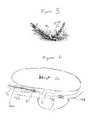
- FIG. 1illustrates a wristwatch in accordance with an embodiment of the present invention.
- FIG. 2illustrates a block diagram of electronic components of the wristwatch of FIG. 1 .
- FIG. 3illustrates a flow chart showing a method of securely operating the wristwatch of FIG. 1 in accordance with an embodiment of the present invention.
- FIG. 4illustrates a wristwatch in accordance with another embodiment of the present invention, showing an optical data channel.
- FIG. 5illustrates operation of the optical data channel of the wristwatch of FIG. 4 .
- FIG. 6illustrates operation of the optical data channel of the wristwatch of FIG. 4 in greater detail.
- FIG. 7illustrates a wristwatch in accordance with another embodiment of the present invention, showing a contacting electrical data channel.
- FIG. 8illustrates a wristwatch in accordance with another embodiment of the present invention, showing a non-contacting electrical data channel.
- FIG. 9illustrates a wristwatch in accordance with another embodiment of the present invention, showing a non-contacting electrical data channel formed by capacitive coupling.
- FIG. 10illustrates a wristwatch in accordance with another embodiment of the present invention, showing a non-contacting electrical data channel formed by inductive coupling.
- FIG. 1illustrates a wristwatch 100 in accordance with an embodiment of the present invention.
- the versatile device 100 of the present inventionis configured to be worn by an authenticated user such that to encircle a part of the authenticated user's body.
- the versatile device 100is implemented as a wristwatch 100 as shown in FIG. 1 .
- the versatile device 100may be implemented as any finger, hand, arm, foot, leg, waist, wrist, or other body worn item, such as a bracelet or armband. It should be understood that the wristwatch 100 may have other configurations.
- the wristwatch 100includes electronic circuitry 50 to host one or more applications, secure authentication/identification data, and transaction data, and to also provide authentication to validate use and possession of the wristwatch 100 by a legitimate user by executing a use-based context security validation scheme.
- the wristwatch 100is configured to facilitate a wireless transaction for an authenticated user and is configured to be worn by the authenticated user such that to encircle a part of the authenticated user, such as the authenticated user's wrist.
- the wireless transactioncan be of any type (e.g., credit card type, debit card type, access control type, etc.).
- the wristwatch 100includes a validation mechanism for controlling use of the wristwatch 100 based on whether the authenticated user continues to wear the wristwatch 100 after initiating use of the wristwatch 100 .
- the validation mechanismincludes a transmitting element 40 , a receiving element 30 , a data channel 80 , and a monitoring component (integrated in the electronic circuitry 50 ) for monitoring the status of the data channel 80 .
- the wristwatch 100executes a context security validation scheme, where authenticated use is determined not only by possession of the wristwatch 100 , but also by its operational context.
- the operational contextwill allow the wristwatch 100 to accept or deny any external service interaction via a wireless link, based on whether the wristwatch 100 is in an active/secure status state or in an inactive state.
- the wristwatch 100includes a data channel 80 integrated within the first and second straps 10 and 20 of the wristwatch 100 itself enabling validation of whether the wristwatch 100 is being worn by the authenticated user that initiated use of the wristwatch 100 . Removal of the wristwatch 100 will invalidate its context security and place the wristwatch 100 in an inactive state, disabling all external interaction via a wireless link.
- the context security validation executed by the wristwatch 100enables valid user authentication and access to services or transactions via a wireless link, which may otherwise be obtained by non-authenticated individuals who obtained the wristwatch by devious means or by accident.
- the concept of a secure device stateprovides additional security and theft redundancy as the wristwatch 100 acts as a host for applications and secure data and no longer solely depends on possession to maintain security.
- the securityis obtained by a combination of the authenticated user wearing the wristwatch 100 and initializing its operation. Therefore, removing the wristwatch 100 will also disable its operational capabilities, thus reducing its value to others.
- the wristwatch body 90acts as the main functional section.
- the wristwatch body 90provides time and date functions via the watchface 60 .
- the wristwatch body 90provides secure data storage capability, wireless transaction capability, and an encryption engine for the validation mechanism.
- the wristwatch 100includes a data channel 80 integrated within the first and second straps 10 and 20 of the wristwatch 100 itself enabling validation of whether the wristwatch 100 is being worn by the authenticated user that initiated use of the wristwatch 100 .
- the wristwatch body 90includes an embedded electronics subsystem 50 , a transmitting element 40 for transmitting data through the data channel 80 , a receiving element 30 for receiving the data transmitted through the data channel 80 , and optional biosensors 70 for sensing whether the authenticated user is wearing the wristwatch 100 .
- a successful transmission of the data between the transmitting element 40 and the receiving element 30indicates that the wristwatch 100 is being worn by the authenticated user.
- the data channel 80is configured to be rendered inoperable if the authenticated user discontinues wearing the wristwatch 100 .
- the data transmitted by the transmitting element 40is transmitted periodically and is time-varying to avoid unauthorized interference with the monitoring of the integrity and status of the data channel 80 .
- the encryption enginefacilitates secure transmission of the data through the data channel 80 .
- the wristwatch 100includes a clasp or strap connection mechanism 85 .
- FIG. 2illustrates a block diagram of electronic components of the wristwatch 100 of FIG. 1 .
- the wristwatch 100includes a microprocessor 84 for monitoring the status of the data channel 80 and executing the context security validation scheme, a read only memory (ROM) 81 , a random access memory (RAM) 82 , a radio frequency (RF) interface 83 , an interface 61 to the watch display 60 , an internal power source 75 , the transmitting (TX) element 40 , the receiving (RX) element 30 , a data bus 76 , and circuits 71 to process the biosensor 70 output signals.
- ROMread only memory
- RAMrandom access memory
- RFradio frequency
- the wristwatch 100is capable of providing a low cost and robust authentication solution by ensuring the integrity of the data channel 80 integrated into the first and second straps 10 and 20 .
- Securitycan be enhanced by using the optional biosensor subsystem 70 and 71 , providing the capability to detect the presence or absence of the authenticated user's body using biometric measurement techniques (e.g., skin temperature, light reflection, humidity), in addition to the integrity of the data channel 80 itself.
- biometric measurement techniquese.g., skin temperature, light reflection, humidity
- FIG. 3illustrates a flow chart showing a method 300 of securely operating the wristwatch 100 of FIG. 1 in accordance with an embodiment of the present invention. Reference is made to FIGS. 1 and 2 .
- a userwears the wristwatch 100 .
- the usergoes through a security initialization procedure to authenticate the user prior to allowing the user general operational use of the wristwatch's 100 application hosting functionality to facilitate a variety of wireless transactions for the authenticated user.
- the initialization proceduremay be a simple wristwatch-based operation (e.g. entering a PIN number on the wristwatch itself) or a more complex security procedure involving an external security system at Block 325 (e.g. an external device with retina scanning hardware could be used to provide unique user verification, which is conveyed to the wristwatch 100 via the encrypted RF data communications link 302 ).
- the initialization processwill also validate the presence of the user's body.
- the wristwatch 100enters an active/secure status state (at Block 330 ) and starts execution (at Block 370 ) of one or more applications, which are configured to facilitate wireless transactions and services.
- the wireless transaction and servicescan be of any type (e.g., credit card type, debit card type, access control type, etc.).
- the particular applicationchecks at Block 380 whether the wristwatch 100 is operating in the active/secure status state. If the wristwatch 100 is not operating in the active/secure status state, the particular application denies the user access to the particular application at Block 390 . Otherwise, the particular application then checks at Block 385 , the validity of the interrogation (e.g., has the user subscribed to the particular service, has the user paid the bill for the particular service). If the interrogation is not valid, the particular application denies the user access to the services offered by the particular application at Block 390 . Otherwise, at Block 395 , the particular application performs the desired service or transaction supported by the particular application.
- the interrogatione.g., has the user subscribed to the particular service, has the user paid the bill for the particular service.
- the integrity of the data channel 80 integrated into the strapsis monitored.
- datais transmitted through the data channel 80 to validate the active/secure status state of the wristwatch 100 .
- the validation processuses its own data for transmission through the data channel 80 , independent from the hosted applications or secure data stored in the wristwatch 100 .
- the wristwatch 100erases (at Block 360 ) its active/secure status state and application data and then switches (at Block 365 ) to an inactive state or off. Once switched off, others cannot use the wristwatch 100 to execute services or transactions. Once switched off, the wristwatch 100 can only be re-activated by the user after wearing the wristwatch 100 and re-performing the initialization procedure described above.
- the optional bio-sensing subsystem(at Block 340 ) provides an extra level of security by determining the user's presence as a supplement to the monitoring of the status and integrity of the data channel 80 . Abnormal changes detected by the biosensors will result in the performance of the operations in Blocks 360 and 365 as described above.
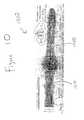
- FIG. 4illustrates a wristwatch 400 in accordance with another embodiment of the present invention, showing an optical data channel 480 A and 480 B.
- the wristwatch 400includes a first and a second plastic straps 450 and 451 and a buckle fastener 485 .
- the buckle fastener 485is typical of those used on most low cost watches.
- Each strap 454 and 450is manufactured so that it has an integrated optical light path 480 A and 480 B.
- the optical light paths 480 A and 480 Bform the optical data channel of the wristwatch 400 . This may be achieved by embedding an optical fiber in each strap. Alternatively, this may be achieved by manufacturing each strap from materials that possess appropriate optical properties.
- FIGS. 5 and 6illustrate operation of the optical data channel 480 A and 480 B of the wristwatch of FIG. 4 in greater detail.
- the location of the user's wrist 77is also shown.
- a light-transmitting element 1transmits light into the fixed length strap 451 at its hinge 2 with the watch body 460 .
- the curvature of the watch body 460 and the strap hinge mechanism 2provide a lens 492 to focus the light into the optical light path 480 A of the strap 451 .
- the lightis refracted and guided to leave the strap 451 at an angle above the buckle connection 4 , directing the light into the other variable length strap 450 .
- the lightthen enters the variable length strap 450 at one of a number of fixed points, determined by the positioning of the variable length strap 450 , i.e. which hole is used to clasp the buckle 485 .
- the geometry of the variable length strap 450includes a ‘saw-tooth’ pattern 5 that coincides with the buckle hole locations 471 . This feature minimizes the air gap and light path between the two straps 451 and 450 , thus ensuring that the light enters the variable length strap 450 close to perpendicular, maximizing the transmitted light energy entering the variable length strap 450 .
- the light within the variable length strap 450is then directed to the second hinge mechanism 6 , which again provides a lens 493 to focus the remaining light energy to a light receiving/detection element 7 .
- the watch body 460 , hinge mechanism 2 and 6 and the straps 450 and 451could be manufactured as a single plastic section, thus making the watch body and straps part of the same optical path, minimizing the number of light interfaces to three, i.e., the transmit and receive elements 1 and 2 and the buckle connection 4 .
- each strap 450 and 451could be windowed, possibly polarized, to ensure that light can only enter or leave the straps at the desired locations. This would assist in both reducing the optical power loss and hence the overall system power requirement and to reduce the possibility of external interference.
- any attempted external eaves dropping of the optical data channelwill not influence the secure functionality of the wristwatch 400 .
- FIG. 7illustrates a wristwatch 700 in accordance with another embodiment of the present invention, showing a contacting electrical data channel.
- the wristwatch 700includes two metal straps 720 and 730 , whereas the contacting electrical data channel is integrated into the metal straps 720 and 730 .
- One possible realization when using a metal strapis to use the clasp mechanism 750 as a switch, only allowing connection for the contacting electrical data channel when the clasp mechanism 750 is in the closed position. Although simple to realize, this type of design would be easy to eaves drop, vulnerable to an electrical by-pass and subject to switch contact or mechanical failure.
- FIG. 8illustrates a wristwatch 800 in accordance with another embodiment of the present invention, showing a non-contacting electrical data channel.
- An advantage offered by this wristwatch 800is that the non-contacting electrical data channel integrated into the straps 810 and 820 used for data transmission can simultaneously provide information about the integrity of the straps 810 and 820 and their connection such as whether the authenticated user has loosen or tightened the straps 810 and 820 .
- one or more electrical properties associated with the non-contacting electrical data channelcan be monitored to determine a status of the non-contacting electrical data channel.
- the non-contacting electrical data channelis more reliable and secure.
- the two straps 810 and 820become the electrical transmit and receive elements and are electrically connected to the watch body 830 and its internal circuitry.
- the non-contacting electrical sensor elements 840are required to detect and validate that the straps 810 and 820 are fastened and facilitate the encrypted data transmission through the non-contacting electrical data channel.
- the manufacture of the wristwatch 800could incorporate seamless rigid (watch electronics) and flexible (watchstrap) printed circuit board techniques, encased by the plastic watch body or other flexible non-conducting protective material.
- FIG. 9illustrates a wristwatch 900 in accordance with another embodiment of the present invention, showing a non-contacting electrical data channel formed by capacitive coupling.
- capacitive plates 930 and 940are embedded into each end of the two straps 910 and 920 to form a parallel plate capacitor with a deterministic capacitance based on the clasp position when worn. This will create a capacitive loop (or a non-contacting electrical data channel formed by capacitive coupling) through which the encrypted data can be transmitted, thus creating the non-contacting electrical data channel for secure data transmission and providing a means to monitor the status of the straps 910 and 920 and the non-contacting electrical data channel formed by capacitive coupling.
- FIG. 10illustrates a wristwatch 1000 in accordance with another embodiment of the present invention, showing a non-contacting electrical data channel formed by inductive coupling.
- each of the straps 1010 and 1020includes an inductive circuit element 1030 and 1040 .
- the mutual inductance coupling between these two inductive elements 1030 and 1040creates a non-contacting electrical data channel for secure data transmission and provides a means to monitor the status of the straps 1010 and 1020 and the non-contacting electrical data channel formed by inductive coupling, as described above.
- periodic measurement of mutual inductancewill validate the integrity of the non-contacting electrical data channel itself. Abnormal changes to this measurement will result in the wristwatch erasing its active/secure status state.
- Appropriate geometric shielding of the inductive circuit element 1030 and 1040 to minimize stray losses and external interferencemay be required.
Landscapes
- Engineering & Computer Science (AREA)
- Computer Security & Cryptography (AREA)
- Physics & Mathematics (AREA)
- General Physics & Mathematics (AREA)
- Computer Networks & Wireless Communication (AREA)
- Signal Processing (AREA)
- Human Computer Interaction (AREA)
- Electric Clocks (AREA)
- User Interface Of Digital Computer (AREA)
Abstract
Description
Claims (20)
Priority Applications (6)
| Application Number | Priority Date | Filing Date | Title |
|---|---|---|---|
| US10/011,925US7474592B2 (en) | 2001-12-05 | 2001-12-05 | Secure operation of a versatile device based on whether an authenticated user continues to wear the versatile device after initiating its use |
| DE60226265TDE60226265T2 (en) | 2001-12-05 | 2002-11-20 | SAFE OPERATION OF A MULTI-PURPOSE EQUIPMENT BASED ON WHETHER THE AUTHENTICATED USER CONTINUES TO OWN THE MULTIPURPOSE UNIT AFTER COMMISSIONING |
| PCT/US2002/037076WO2003054814A2 (en) | 2001-12-05 | 2002-11-20 | Secure operation of a versatile device based on whether an authenticated user continues to wear the versatile device after initiating its use |
| EP02782321AEP1450640B1 (en) | 2001-12-05 | 2002-11-20 | Secure operation of a versatile device based on whether an authenticated user continues to wear the versatile device after initiating its use |
| JP2003555455AJP4426844B2 (en) | 2001-12-05 | 2002-11-20 | Secure operation of universal device based on whether authenticated user continues to wear universal device after starting use |
| AU2002348296AAU2002348296A1 (en) | 2001-12-05 | 2002-11-20 | Secure operation of a versatile device based on whether an authenticated user continues to wear the versatile device after initiating its use |
Applications Claiming Priority (1)
| Application Number | Priority Date | Filing Date | Title |
|---|---|---|---|
| US10/011,925US7474592B2 (en) | 2001-12-05 | 2001-12-05 | Secure operation of a versatile device based on whether an authenticated user continues to wear the versatile device after initiating its use |
Publications (2)
| Publication Number | Publication Date |
|---|---|
| US20030103414A1 US20030103414A1 (en) | 2003-06-05 |
| US7474592B2true US7474592B2 (en) | 2009-01-06 |
Family
ID=21752551
Family Applications (1)
| Application Number | Title | Priority Date | Filing Date |
|---|---|---|---|
| US10/011,925Expired - Fee RelatedUS7474592B2 (en) | 2001-12-05 | 2001-12-05 | Secure operation of a versatile device based on whether an authenticated user continues to wear the versatile device after initiating its use |
Country Status (6)
| Country | Link |
|---|---|
| US (1) | US7474592B2 (en) |
| EP (1) | EP1450640B1 (en) |
| JP (1) | JP4426844B2 (en) |
| AU (1) | AU2002348296A1 (en) |
| DE (1) | DE60226265T2 (en) |
| WO (1) | WO2003054814A2 (en) |
Cited By (22)
| Publication number | Priority date | Publication date | Assignee | Title |
|---|---|---|---|---|
| US9091715B2 (en) | 2013-02-25 | 2015-07-28 | Google Technology Holdings LLC | Wearable device with capacitive sensor and method of operation therefor |
| US20160080936A1 (en)* | 2014-09-16 | 2016-03-17 | Samsung Electronics Co., Ltd. | Systems and methods for device based authentication |
| US9423418B2 (en) | 2013-02-25 | 2016-08-23 | Google Technology Holdings LLC | Capacitive sensor |
| US9461386B1 (en)* | 2015-10-09 | 2016-10-04 | Pebble Technology, Corp. | Spring pin electrical connector |
| US9566717B2 (en) | 2013-01-22 | 2017-02-14 | 3M Innovative Properties Company | Apparatus for cutting electronic monitoring bracelet straps |
| US10104089B2 (en) | 2014-06-02 | 2018-10-16 | Samsung Electronics Co., Ltd. | Method and apparatus for providing security function |
| US11285375B1 (en) | 2011-04-29 | 2022-03-29 | Bryan Marc Failing | Sports board configuration |
| DE112015003882B4 (en) | 2014-08-26 | 2023-04-27 | Toyota Motor Sales, U.S.A., Inc. | Integrated wearable item for interactive vehicle control system |
| US11815860B2 (en) | 2020-06-02 | 2023-11-14 | Apple Inc. | Switch module for electronic crown assembly |
| US11860587B2 (en) | 2019-02-12 | 2024-01-02 | Apple Inc. | Variable frictional feedback device for a digital crown of an electronic watch |
| US11988995B2 (en) | 2015-03-08 | 2024-05-21 | Apple Inc. | Compressible seal for rotatable and translatable input mechanisms |
| US12045416B2 (en) | 2014-02-12 | 2024-07-23 | Apple Inc. | Rejection of false turns of rotary inputs for electronic devices |
| US12066795B2 (en) | 2017-07-18 | 2024-08-20 | Apple Inc. | Tri-axis force sensor |
| US12086331B2 (en) | 2016-07-15 | 2024-09-10 | Apple Inc. | Capacitive gap sensor ring for an input device |
| US12092996B2 (en) | 2021-07-16 | 2024-09-17 | Apple Inc. | Laser-based rotation sensor for a crown of an electronic watch |
| US12105480B2 (en) | 2018-06-25 | 2024-10-01 | Apple Inc. | Crown for an electronic watch |
| US12104929B2 (en) | 2016-05-17 | 2024-10-01 | Apple Inc. | Rotatable crown for an electronic device |
| US12181840B2 (en) | 2013-08-09 | 2024-12-31 | Apple Inc. | Tactile switch for an electronic device |
| US12189347B2 (en) | 2022-06-14 | 2025-01-07 | Apple Inc. | Rotation sensor for a crown of an electronic watch |
| US12259690B2 (en) | 2018-08-24 | 2025-03-25 | Apple Inc. | Watch crown having a conductive surface |
| US12282302B2 (en) | 2018-08-02 | 2025-04-22 | Apple Inc. | Crown for an electronic watch |
| US12396686B2 (en) | 2021-08-31 | 2025-08-26 | Apple Inc. | Sensing health parameters in wearable devices |
Families Citing this family (34)
| Publication number | Priority date | Publication date | Assignee | Title |
|---|---|---|---|---|
| DE10001929A1 (en)* | 2000-01-19 | 2001-08-09 | Skidata Ag | Authorization control facility |
| USH2120H1 (en)* | 2002-10-10 | 2005-07-05 | The United States Of America As Represented By The Secretary Of The Air Force | Biometric personal identification credential system (PICS) |
| US20040151071A1 (en)* | 2003-02-04 | 2004-08-05 | Kocher Robert William | Wrist-mounted electronic computer component (WECC) |
| EP2016536A4 (en)* | 2006-04-18 | 2011-06-29 | Cfph Llc | Systems and methods for providing access to wireless gaming devices |
| US7549576B2 (en) | 2006-05-05 | 2009-06-23 | Cfph, L.L.C. | Systems and methods for providing access to wireless gaming devices |
| DE102007025920B4 (en)* | 2007-06-02 | 2009-10-29 | Imst Gmbh | Decorative jewelry with built-in electronic circuit, which has an integrated electronic data storage |
| GB2457335A (en)* | 2008-01-21 | 2009-08-19 | H W Comm Ltd | A wearable device indicating if a current wearer is the habitual wearer of the device. |
| US8976007B2 (en)* | 2008-08-09 | 2015-03-10 | Brian M. Dugan | Systems and methods for providing biofeedback information to a cellular telephone and for using such information |
| US8253542B2 (en)* | 2008-09-04 | 2012-08-28 | Disney Enterprises, Inc. | Method and system for performing affinity transactions |
| US20100052916A1 (en)* | 2008-09-04 | 2010-03-04 | Disney Enterprises, Inc | Identification band with secured association to wearer |
| KR101595384B1 (en)* | 2009-07-20 | 2016-02-18 | 엘지전자 주식회사 | Watch type mobile terminal |
| US20140089672A1 (en)* | 2012-09-25 | 2014-03-27 | Aliphcom | Wearable device and method to generate biometric identifier for authentication using near-field communications |
| JP2013191135A (en)* | 2012-03-15 | 2013-09-26 | Fujitsu Ltd | Authentication system, processing device, and program |
| US9305153B1 (en)* | 2012-06-29 | 2016-04-05 | Emc Corporation | User authentication |
| EP2733654A1 (en)* | 2012-11-20 | 2014-05-21 | Nagravision S.A. | Electronic payment method, system and device for securely exchanging payment information |
| US9832206B2 (en) | 2013-03-21 | 2017-11-28 | The Trustees Of Dartmouth College | System, method and authorization device for biometric access control to digital devices |
| US9231765B2 (en)* | 2013-06-18 | 2016-01-05 | Arm Ip Limited | Trusted device |
| GB2517417B (en) | 2013-08-19 | 2017-10-11 | Arm Ip Ltd | Wrist-worn device clasp |
| AT514861A3 (en) | 2013-09-20 | 2015-05-15 | Asmag Holding Gmbh | Authentication system for a mobile data terminal |
| GB2521614B (en)* | 2013-12-23 | 2021-01-13 | Arm Ip Ltd | Controlling authorisation within computer systems |
| US9720376B2 (en) | 2014-11-18 | 2017-08-01 | Sony Corporation | Band type electronic device and substrate arrangement method |
| KR102371943B1 (en)* | 2015-02-24 | 2022-03-08 | 삼성전자 주식회사 | Handheld electronic device capable of magnetic field communication and payment method using the same |
| EP3118762B1 (en)* | 2015-07-15 | 2020-03-11 | Biowatch SA | Method, device and computer program for authenticating a user |
| US20170237267A1 (en)* | 2016-02-12 | 2017-08-17 | Qualcomm Incorporated | Wireless power receiving element with capacitive coupling |
| US20190053739A1 (en)* | 2016-02-24 | 2019-02-21 | Seiko Epson Corporation | Wearable apparatus, settlement system, and settlement method |
| WO2017145730A1 (en)* | 2016-02-24 | 2017-08-31 | セイコーエプソン株式会社 | Wearable device |
| JP2017151943A (en)* | 2016-02-24 | 2017-08-31 | セイコーエプソン株式会社 | Wearing device, payment system and payment method |
| US10175653B1 (en)* | 2016-09-21 | 2019-01-08 | Apple Inc. | Watch glow light band |
| US9961547B1 (en) | 2016-09-30 | 2018-05-01 | EMC IP Holding Company LLC | Continuous seamless mobile device authentication using a separate electronic wearable apparatus |
| US20190033787A1 (en)* | 2017-07-25 | 2019-01-31 | Evan Swanagin | Device and method for emitting light away from a user |
| US11165141B2 (en) | 2018-05-01 | 2021-11-02 | Apple Inc. | Antenna assemblies for watch bands |
| US11315404B1 (en)* | 2018-12-27 | 2022-04-26 | Brian A. Greer | Wearable proximity alert system |
| CN109375497B (en)* | 2018-12-29 | 2020-11-06 | 北京工业大学 | Wireless rechargeable smart watch capable of detecting emotion change based on convolutional neural network |
| US11512926B2 (en)* | 2021-02-18 | 2022-11-29 | Locking Control Ltd. | Wrist band device for releasing holster lock |
Citations (16)
| Publication number | Priority date | Publication date | Assignee | Title |
|---|---|---|---|---|
| US4736196A (en) | 1986-11-18 | 1988-04-05 | Cost-Effective Monitoring Systems, Co. | Electronic monitoring system |
| WO1988009541A1 (en)* | 1987-05-26 | 1988-12-01 | Cogema Compagnie Generale Des Matieres Nucleaires | Person identification system |
| US5537102A (en)* | 1991-08-13 | 1996-07-16 | Electronic Monitoring Systems, Inc. | Apparatus and method for a system capable of remotely validating the identity of individual and their location |
| EP0774737A2 (en) | 1995-11-16 | 1997-05-21 | Ncr International Inc. | An authorization device |
| WO1998012670A1 (en) | 1996-09-18 | 1998-03-26 | Dew Engineering And Development Limited | Biometric identification system for providing secure access |
| US5883576A (en)* | 1998-01-14 | 1999-03-16 | De La Huerga; Carlos | Identification bracelet with electronics information |
| US5936530A (en)* | 1998-04-02 | 1999-08-10 | Meinhold; Robert C. | Child protection device |
| WO2000005686A1 (en) | 1998-07-21 | 2000-02-03 | Skidata Ag | Contactless data carrier |
| EP1014231A1 (en) | 1998-12-22 | 2000-06-28 | Eta SA Fabriques d'Ebauches | Wrist watch with capacitive coupling |
| US6158884A (en)* | 1998-06-26 | 2000-12-12 | Motorola, Inc. | Integrated communicative watch |
| WO2001018332A1 (en) | 1999-09-06 | 2001-03-15 | Siemens Aktiengesellschaft | Activation of secured objects |
| US6255951B1 (en) | 1996-12-20 | 2001-07-03 | Carlos De La Huerga | Electronic identification bracelet |
| US6350055B1 (en)* | 1998-12-22 | 2002-02-26 | Eta Sa Fabriques D'ebauches | Wristwatch with capacitive coupling |
| US6396403B1 (en)* | 1999-04-15 | 2002-05-28 | Lenora A. Haner | Child monitoring system |
| US20030099459A1 (en)* | 2000-11-10 | 2003-05-29 | Noboru Yanagita | Program additional data creating device, video program editing device, and video program data creating device |
| US7133843B2 (en)* | 1999-12-30 | 2006-11-07 | International Business Machines Corporation | Easy check-out with enhanced security |
Family Cites Families (4)
| Publication number | Priority date | Publication date | Assignee | Title |
|---|---|---|---|---|
| JP2000148860A (en)* | 1998-11-17 | 2000-05-30 | Seiko Instruments Inc | Authentication terminal and wristwatch type ID device for credit transaction system |
| JP4126385B2 (en)* | 1998-12-31 | 2008-07-30 | カシオ計算機株式会社 | Body wearing device and authentication system |
| JP2001179121A (en)* | 1999-12-27 | 2001-07-03 | Nippon Riiingu Kk | Pulverizing machine |
| JP3431134B2 (en)* | 2000-03-17 | 2003-07-28 | ケイエステクノ株式会社 | Security system |
- 2001
- 2001-12-05USUS10/011,925patent/US7474592B2/ennot_activeExpired - Fee Related
- 2002
- 2002-11-20EPEP02782321Apatent/EP1450640B1/ennot_activeExpired - Lifetime
- 2002-11-20JPJP2003555455Apatent/JP4426844B2/ennot_activeExpired - Fee Related
- 2002-11-20DEDE60226265Tpatent/DE60226265T2/ennot_activeExpired - Lifetime
- 2002-11-20WOPCT/US2002/037076patent/WO2003054814A2/enactiveApplication Filing
- 2002-11-20AUAU2002348296Apatent/AU2002348296A1/ennot_activeAbandoned
Patent Citations (18)
| Publication number | Priority date | Publication date | Assignee | Title |
|---|---|---|---|---|
| US4736196A (en) | 1986-11-18 | 1988-04-05 | Cost-Effective Monitoring Systems, Co. | Electronic monitoring system |
| WO1988009541A1 (en)* | 1987-05-26 | 1988-12-01 | Cogema Compagnie Generale Des Matieres Nucleaires | Person identification system |
| EP0295985A1 (en) | 1987-05-26 | 1988-12-21 | Compagnie Generale Des Matieres Nucleaires (Cogema) | Identification system for individuals |
| US5537102A (en)* | 1991-08-13 | 1996-07-16 | Electronic Monitoring Systems, Inc. | Apparatus and method for a system capable of remotely validating the identity of individual and their location |
| EP0774737A2 (en) | 1995-11-16 | 1997-05-21 | Ncr International Inc. | An authorization device |
| WO1998012670A1 (en) | 1996-09-18 | 1998-03-26 | Dew Engineering And Development Limited | Biometric identification system for providing secure access |
| US6255951B1 (en) | 1996-12-20 | 2001-07-03 | Carlos De La Huerga | Electronic identification bracelet |
| US5883576A (en)* | 1998-01-14 | 1999-03-16 | De La Huerga; Carlos | Identification bracelet with electronics information |
| US5936530A (en)* | 1998-04-02 | 1999-08-10 | Meinhold; Robert C. | Child protection device |
| US6158884A (en)* | 1998-06-26 | 2000-12-12 | Motorola, Inc. | Integrated communicative watch |
| WO2000005686A1 (en) | 1998-07-21 | 2000-02-03 | Skidata Ag | Contactless data carrier |
| US6431455B1 (en)* | 1998-07-21 | 2002-08-13 | Skidata Ag | Contactless data carrier |
| EP1014231A1 (en) | 1998-12-22 | 2000-06-28 | Eta SA Fabriques d'Ebauches | Wrist watch with capacitive coupling |
| US6350055B1 (en)* | 1998-12-22 | 2002-02-26 | Eta Sa Fabriques D'ebauches | Wristwatch with capacitive coupling |
| US6396403B1 (en)* | 1999-04-15 | 2002-05-28 | Lenora A. Haner | Child monitoring system |
| WO2001018332A1 (en) | 1999-09-06 | 2001-03-15 | Siemens Aktiengesellschaft | Activation of secured objects |
| US7133843B2 (en)* | 1999-12-30 | 2006-11-07 | International Business Machines Corporation | Easy check-out with enhanced security |
| US20030099459A1 (en)* | 2000-11-10 | 2003-05-29 | Noboru Yanagita | Program additional data creating device, video program editing device, and video program data creating device |
Cited By (31)
| Publication number | Priority date | Publication date | Assignee | Title |
|---|---|---|---|---|
| US11285375B1 (en) | 2011-04-29 | 2022-03-29 | Bryan Marc Failing | Sports board configuration |
| US12296251B1 (en)* | 2011-04-29 | 2025-05-13 | Bryan Marc Failing | Sports board configuration |
| US11724174B1 (en) | 2011-04-29 | 2023-08-15 | Bryan Marc Failing | Sports board configuration |
| US9566717B2 (en) | 2013-01-22 | 2017-02-14 | 3M Innovative Properties Company | Apparatus for cutting electronic monitoring bracelet straps |
| US9796100B2 (en) | 2013-01-22 | 2017-10-24 | 3M Innovative Properties Company | Apparatus for cutting electronic monitoring bracelet straps |
| US9423418B2 (en) | 2013-02-25 | 2016-08-23 | Google Technology Holdings LLC | Capacitive sensor |
| US9091715B2 (en) | 2013-02-25 | 2015-07-28 | Google Technology Holdings LLC | Wearable device with capacitive sensor and method of operation therefor |
| US12181840B2 (en) | 2013-08-09 | 2024-12-31 | Apple Inc. | Tactile switch for an electronic device |
| US12045416B2 (en) | 2014-02-12 | 2024-07-23 | Apple Inc. | Rejection of false turns of rotary inputs for electronic devices |
| US12307047B2 (en) | 2014-02-12 | 2025-05-20 | Apple Inc. | Rejection of false turns of rotary inputs for electronic devices |
| US10104089B2 (en) | 2014-06-02 | 2018-10-16 | Samsung Electronics Co., Ltd. | Method and apparatus for providing security function |
| DE112015003882B4 (en) | 2014-08-26 | 2023-04-27 | Toyota Motor Sales, U.S.A., Inc. | Integrated wearable item for interactive vehicle control system |
| CN105426714B (en)* | 2014-09-16 | 2019-02-19 | 三星电子株式会社 | System and method for device-based authentication |
| US9743279B2 (en)* | 2014-09-16 | 2017-08-22 | Samsung Electronics Co., Ltd. | Systems and methods for device based authentication |
| CN105426714A (en)* | 2014-09-16 | 2016-03-23 | 三星电子株式会社 | Systems and methods for device based authentication |
| US20160080936A1 (en)* | 2014-09-16 | 2016-03-17 | Samsung Electronics Co., Ltd. | Systems and methods for device based authentication |
| US11988995B2 (en) | 2015-03-08 | 2024-05-21 | Apple Inc. | Compressible seal for rotatable and translatable input mechanisms |
| US9461386B1 (en)* | 2015-10-09 | 2016-10-04 | Pebble Technology, Corp. | Spring pin electrical connector |
| US12104929B2 (en) | 2016-05-17 | 2024-10-01 | Apple Inc. | Rotatable crown for an electronic device |
| US12086331B2 (en) | 2016-07-15 | 2024-09-10 | Apple Inc. | Capacitive gap sensor ring for an input device |
| US12066795B2 (en) | 2017-07-18 | 2024-08-20 | Apple Inc. | Tri-axis force sensor |
| US12105480B2 (en) | 2018-06-25 | 2024-10-01 | Apple Inc. | Crown for an electronic watch |
| US12282302B2 (en) | 2018-08-02 | 2025-04-22 | Apple Inc. | Crown for an electronic watch |
| US12259690B2 (en) | 2018-08-24 | 2025-03-25 | Apple Inc. | Watch crown having a conductive surface |
| US11860587B2 (en) | 2019-02-12 | 2024-01-02 | Apple Inc. | Variable frictional feedback device for a digital crown of an electronic watch |
| US12346070B2 (en) | 2019-02-12 | 2025-07-01 | Apple Inc. | Variable frictional feedback device for a digital crown of an electronic watch |
| US12189342B2 (en) | 2020-06-02 | 2025-01-07 | Apple Inc. | Switch module for electronic crown assembly |
| US11815860B2 (en) | 2020-06-02 | 2023-11-14 | Apple Inc. | Switch module for electronic crown assembly |
| US12092996B2 (en) | 2021-07-16 | 2024-09-17 | Apple Inc. | Laser-based rotation sensor for a crown of an electronic watch |
| US12396686B2 (en) | 2021-08-31 | 2025-08-26 | Apple Inc. | Sensing health parameters in wearable devices |
| US12189347B2 (en) | 2022-06-14 | 2025-01-07 | Apple Inc. | Rotation sensor for a crown of an electronic watch |
Also Published As
| Publication number | Publication date |
|---|---|
| WO2003054814A2 (en) | 2003-07-03 |
| EP1450640A2 (en) | 2004-09-01 |
| US20030103414A1 (en) | 2003-06-05 |
| JP2005538430A (en) | 2005-12-15 |
| AU2002348296A1 (en) | 2003-07-09 |
| JP4426844B2 (en) | 2010-03-03 |
| WO2003054814A3 (en) | 2004-03-11 |
| DE60226265T2 (en) | 2008-12-18 |
| EP1450640B1 (en) | 2008-04-23 |
| DE60226265D1 (en) | 2008-06-05 |
| AU2002348296A8 (en) | 2003-07-09 |
Similar Documents
| Publication | Publication Date | Title |
|---|---|---|
| US7474592B2 (en) | Secure operation of a versatile device based on whether an authenticated user continues to wear the versatile device after initiating its use | |
| US8899487B2 (en) | Biometric identity verification system and method | |
| US7742995B2 (en) | Pre-authenticated identification token | |
| US20030046228A1 (en) | User-wearable functional jewelry with biometrics and smartcard to remotely sign and/or authenticate to e-services | |
| AU2008248013B2 (en) | Dynamically programmable RFID transponder | |
| EP3631663B1 (en) | Smartcard and method for controlling a smartcard | |
| US8730012B2 (en) | Enabling identification token for a timed period | |
| US20150286922A1 (en) | Biometric identity verification system and method | |
| JP2018142348A (en) | Multiple application chip card having biometrics | |
| US20160057627A1 (en) | Method and Apparatus for Preventing Concealed, Unauthorized Wireless Data Access | |
| US20230334131A1 (en) | Biometrically protected device | |
| US20190251236A1 (en) | Biometric device | |
| WO2019154504A1 (en) | Fingerprint authorisable device | |
| JP2003132031A (en) | Data communication device | |
| JP6432359B2 (en) | Information processing apparatus and program | |
| WO2018087336A1 (en) | Fingerprint authorisable demonstrator device |
Legal Events
| Date | Code | Title | Description |
|---|---|---|---|
| AS | Assignment | Owner name:HEWLETT-PACKARD COMPANY, COLORADO Free format text:ASSIGNMENT OF ASSIGNORS INTEREST;ASSIGNOR:LYON, GEOFFREY MARTIN;REEL/FRAME:012898/0196 Effective date:20011130 | |
| AS | Assignment | Owner name:HEWLETT-PACKARD DEVELOPMENT COMPANY L.P., TEXAS Free format text:ASSIGNMENT OF ASSIGNORS INTEREST;ASSIGNOR:HEWLETT-PACKARD COMPANY;REEL/FRAME:014061/0492 Effective date:20030926 Owner name:HEWLETT-PACKARD DEVELOPMENT COMPANY L.P.,TEXAS Free format text:ASSIGNMENT OF ASSIGNORS INTEREST;ASSIGNOR:HEWLETT-PACKARD COMPANY;REEL/FRAME:014061/0492 Effective date:20030926 | |
| STCF | Information on status: patent grant | Free format text:PATENTED CASE | |
| FPAY | Fee payment | Year of fee payment:4 | |
| FPAY | Fee payment | Year of fee payment:8 | |
| FEPP | Fee payment procedure | Free format text:MAINTENANCE FEE REMINDER MAILED (ORIGINAL EVENT CODE: REM.); ENTITY STATUS OF PATENT OWNER: LARGE ENTITY | |
| LAPS | Lapse for failure to pay maintenance fees | Free format text:PATENT EXPIRED FOR FAILURE TO PAY MAINTENANCE FEES (ORIGINAL EVENT CODE: EXP.); ENTITY STATUS OF PATENT OWNER: LARGE ENTITY | |
| STCH | Information on status: patent discontinuation | Free format text:PATENT EXPIRED DUE TO NONPAYMENT OF MAINTENANCE FEES UNDER 37 CFR 1.362 | |
| FP | Lapsed due to failure to pay maintenance fee | Effective date:20210106 |