US7474073B2 - Method and system for multiple servo motor control using a single control loop - Google Patents
Method and system for multiple servo motor control using a single control loopDownload PDFInfo
- Publication number
- US7474073B2 US7474073B2US11/601,496US60149606AUS7474073B2US 7474073 B2US7474073 B2US 7474073B2US 60149606 AUS60149606 AUS 60149606AUS 7474073 B2US7474073 B2US 7474073B2
- Authority
- US
- United States
- Prior art keywords
- signal
- mechanical load
- motors
- servo motors
- coupled
- Prior art date
- Legal status (The legal status is an assumption and is not a legal conclusion. Google has not performed a legal analysis and makes no representation as to the accuracy of the status listed.)
- Active, expires
Links
- 238000000034methodMethods0.000titleclaimsdescription13
- 238000006243chemical reactionMethods0.000claimsabstractdescription7
- 230000008878couplingEffects0.000claimsdescription4
- 238000010168coupling processMethods0.000claimsdescription4
- 238000005859coupling reactionMethods0.000claimsdescription4
- 238000004804windingMethods0.000claimsdescription4
- 230000007246mechanismEffects0.000abstractdescription8
- 238000010586diagramMethods0.000description2
- 238000010438heat treatmentMethods0.000description1
- 238000004806packaging method and processMethods0.000description1
- 230000000737periodic effectEffects0.000description1
- 230000002459sustained effectEffects0.000description1
Images


Classifications
- H—ELECTRICITY
- H02—GENERATION; CONVERSION OR DISTRIBUTION OF ELECTRIC POWER
- H02P—CONTROL OR REGULATION OF ELECTRIC MOTORS, ELECTRIC GENERATORS OR DYNAMO-ELECTRIC CONVERTERS; CONTROLLING TRANSFORMERS, REACTORS OR CHOKE COILS
- H02P5/00—Arrangements specially adapted for regulating or controlling the speed or torque of two or more electric motors
- H02P5/46—Arrangements specially adapted for regulating or controlling the speed or torque of two or more electric motors for speed regulation of two or more dynamo-electric motors in relation to one another
- H02P5/52—Arrangements specially adapted for regulating or controlling the speed or torque of two or more electric motors for speed regulation of two or more dynamo-electric motors in relation to one another additionally providing control of relative angular displacement
- H02P5/56—Speed and position comparison between the motors by electrical means
Definitions
- the present inventionrelates to improved control of multiple servo motors that are coupled to a common mechanical load.
- Inserter machinessuch as those produced by Pitney Bowes Inc. are used by organizations to produce large volumes of mail at very high speeds. These machines must be capable of handling sheets and collations of paper very quickly and precisely. In recent designs, it has been found that servo motors are well suited for executing the demanding and precise motion profiles needed for transporting paper in these systems.
- design requirements for output mechanical power or torqueare increased to exceed the capability of the originally selected motor and drive. This forces the design engineer to consider one or more of the following options: reduction of mechanical loads, reduction of performance requirements, or use of a higher output motor and drive.
- AC servo motor systemsFor mechanisms that require more output torque or power than less expensive 1 ⁇ 3 horsepower DC servo motor systems, AC servo motor systems are frequently considered as a practical option. However, the incremental price increase to implement an AC servo motor system can be disproportionably more than the additional output power or torque required of the mechanism and motion profile.
- the inventioninvolves the use of two motors to drive a single mechanical load. By doing this, a lower system cost might be achieved instead of using a larger one motor system solution. Unlike solutions that utilize multiple outer control loops to control multiple motors, this invention uses only one outer control loop. By use of this method, complex system instabilities associated with multiple control loops can be eliminated. Furthermore, the invention need not be limited to two motors systems as any number of motor systems may be added to drive a common mechanical load without compromising system stability or working against one another.
- the single control loopincludes a position sensing device coupled to a first of the plurality of servo motors and generating a position signal.
- a signal comparatorreceives the position signal and compares the position signal with a predetermined position based on a desired motion profile. The difference from the actual position and the motion profile is output as a position error signal.
- a signal converterreceives the position error signal and derives a conversion signal (analog or digital) based on the error signal.
- the analog gain signalis provided to a plurality of signal amplifiers, which in turn are coupled to the plurality of servo motors.
- the amplifiersprovide power to the motors for driving the mechanical load.
- FIG. 1is a block diagram that illustrates typical position control elements for a closed-loop servo motor system.
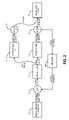
- FIG. 2is a block diagram that illustrates the position control elements for a two motor system.
- FIG. 3is a diagrammatic representation of a typical mechanical implementation using a two motor system.
- a motion profile generator 10injects a desired position into a summing junction 11 , also referred to herein as a comparator. Actual position is subtracted from the desired position to provide a position error. This error is injected into a digital filter 12 that outputs a DAC (digital to analog converter) value.
- the digital filter 12is most commonly a known PID (Proportional, Integral, Derivative) filter but can be any suitable algorithm that converts position error into a DAC power stage 13 (also referred to as an amplifier or drive) value to a motor 14 that ultimately provides the desired quality of motion at the mechanical load 15 .
- PIDProportional, Integral, Derivative
- the DAC valueis scaled accordingly to match the inputs and outputs of the power stage or amplifier 13 .
- many commercially available amplifiers 13use ⁇ 10 VDC as an acceptable analog input signal.
- the power stage 13converts this input signal and outputs a winding current that is proportional to the input signal.
- the digital filter 12may output a digital value whereby the power stage 13 can accept this digital value and accomplish the same as the analog version.
- Winding currentis delivered to the motor 14 and is typically proportional to motor 14 output torque. This ultimately provides motion to the mechanism 15 .
- An encoder 16 or other suitable feedback device located on the motor 14 or on the mechanism 15provides the actual position back to the summing junction 11 , completing the outer closed loop. (The control loop within the power stage 13 that regulates output current is commonly referred to as an inner loop.)
- this entire processtypically updates at a period of 500 microseconds (or 2 KHz), ultimately providing the desired quality of motion at the mechanism 15 .
- Quality of motiongenerally refers to one or more of the following metrics; position error, velocity overshoot and settling time. If the motor 15 and power stage 13 is not adequately sized, the desired quality of motion cannot be achieved and/or be sustained over periods of continuous operation.
- FIG. 2illustrates the position control elements for a two motor system.
- One motor 25Motor 1 or the main motor
- the second motor 26Motor 2 or the helper motor
- output torquecan be effectively doubled.
- a position sensing device 28is coupled to one of the motors 25 , 26 to provide feedback on the motor position.
- the position sensing deviceis an encoder 28 .
- the position sensing device 28can be coupled to the mechanical load 27 , the position of which will be a function of the motor 25 .
- the actual positionis provided from the position sensing device 28 to a comparator 21 (or summing device).
- the comparator 21compares the actual position with a motion profile provided from a motion profile generator 20 .
- a motion profileis a predetermined sequence of positions and timing required for proper operation of the machinery.
- the difference found by comparator 21is a position error signal that is provided to the digital filter 22 .
- the digital filter 22must convert the position error signal to a signal suitable for controlling the motors 25 , 26 .
- the digital filter 22can be tuned using conventional means once both motors 25 , 26 are coupled to the load 27 and the control system is enabled. Since the two motors 25 , 26 can provide double the torque over the one motor system, the gains within the digital filter 22 must be reduced accordingly to preserve servo system stability.
- the mechanical coupling of the two motors 25 , 26can be accomplished in a number of ways including direct coupling, through separate timing belts or through a common timing belt 35 ( FIG. 3 ) For those systems where the direction of motion for one motor is opposite of the other to achieve the same direction on the mechanism, the polarity of the DAC value can be inverted for the helper motor 26 .
- this inventionuses only one outer control loop.
- complex system instabilities associated with multiple control loopscan be eliminated.
- the polarity of the torque directionis always the same for both motor systems, this guarantees that the systems will never be working against one another, thereby minimizing motor heating and electrical power consumption.
- the inventionneed not be limited to two motors systems as any number of motor systems may be added to drive a common mechanical load without compromising system stability.
Landscapes
- Engineering & Computer Science (AREA)
- Power Engineering (AREA)
- Control Of Multiple Motors (AREA)
Abstract
Description
Claims (15)
Priority Applications (1)
| Application Number | Priority Date | Filing Date | Title |
|---|---|---|---|
| US11/601,496US7474073B2 (en) | 2006-11-17 | 2006-11-17 | Method and system for multiple servo motor control using a single control loop |
Applications Claiming Priority (1)
| Application Number | Priority Date | Filing Date | Title |
|---|---|---|---|
| US11/601,496US7474073B2 (en) | 2006-11-17 | 2006-11-17 | Method and system for multiple servo motor control using a single control loop |
Publications (2)
| Publication Number | Publication Date |
|---|---|
| US20080116836A1 US20080116836A1 (en) | 2008-05-22 |
| US7474073B2true US7474073B2 (en) | 2009-01-06 |
Family
ID=39416259
Family Applications (1)
| Application Number | Title | Priority Date | Filing Date |
|---|---|---|---|
| US11/601,496Active2027-04-03US7474073B2 (en) | 2006-11-17 | 2006-11-17 | Method and system for multiple servo motor control using a single control loop |
Country Status (1)
| Country | Link |
|---|---|
| US (1) | US7474073B2 (en) |
Cited By (2)
| Publication number | Priority date | Publication date | Assignee | Title |
|---|---|---|---|---|
| US20080145249A1 (en)* | 2005-03-17 | 2008-06-19 | Smisson-Cartledge Biomedical Llc | Dynamic Range Motor For A Pump Device |
| US11215477B2 (en) | 2020-03-11 | 2022-01-04 | Hamilton Sundstrand Corporation | Motor control systems for multiple motor drives |
Families Citing this family (3)
| Publication number | Priority date | Publication date | Assignee | Title |
|---|---|---|---|---|
| JP5996148B1 (en)* | 2015-04-23 | 2016-09-21 | 三菱電機株式会社 | Multi-axis control system setting adjustment support device |
| CN108418477B (en)* | 2018-02-09 | 2020-06-26 | 福建海睿达科技有限公司 | Synchronous control method of motor, electronic equipment and device with storage function |
| WO2019195436A1 (en) | 2018-04-03 | 2019-10-10 | Digital Check Corp | Film transport apparatus controller and related methods |
Citations (3)
| Publication number | Priority date | Publication date | Assignee | Title |
|---|---|---|---|---|
| US6046566A (en)* | 1998-04-21 | 2000-04-04 | Fanuc Ltd. | Method of and apparatus for controlling a plurality of servomotors |
| US6298779B1 (en)* | 1998-11-11 | 2001-10-09 | Toshiba Kikai Kabushiki Kaisha | Rotary press |
| US6384861B1 (en)* | 1998-12-22 | 2002-05-07 | Gateway, Inc | Image capture device having cursor generating and control apparatus |
- 2006
- 2006-11-17USUS11/601,496patent/US7474073B2/enactiveActive
Patent Citations (3)
| Publication number | Priority date | Publication date | Assignee | Title |
|---|---|---|---|---|
| US6046566A (en)* | 1998-04-21 | 2000-04-04 | Fanuc Ltd. | Method of and apparatus for controlling a plurality of servomotors |
| US6298779B1 (en)* | 1998-11-11 | 2001-10-09 | Toshiba Kikai Kabushiki Kaisha | Rotary press |
| US6384861B1 (en)* | 1998-12-22 | 2002-05-07 | Gateway, Inc | Image capture device having cursor generating and control apparatus |
Cited By (3)
| Publication number | Priority date | Publication date | Assignee | Title |
|---|---|---|---|---|
| US20080145249A1 (en)* | 2005-03-17 | 2008-06-19 | Smisson-Cartledge Biomedical Llc | Dynamic Range Motor For A Pump Device |
| US8360737B2 (en)* | 2005-03-17 | 2013-01-29 | Smisson-Cartledge Biomedical Llc | Dynamic range motor for a pump device |
| US11215477B2 (en) | 2020-03-11 | 2022-01-04 | Hamilton Sundstrand Corporation | Motor control systems for multiple motor drives |
Also Published As
| Publication number | Publication date |
|---|---|
| US20080116836A1 (en) | 2008-05-22 |
Similar Documents
| Publication | Publication Date | Title |
|---|---|---|
| US7474073B2 (en) | Method and system for multiple servo motor control using a single control loop | |
| US7847526B2 (en) | System and method for controlling torque ripples in synchronous machines | |
| JP3567808B2 (en) | Maximum power control method for solar cells | |
| EP3457247B1 (en) | Motor control system | |
| JP4815239B2 (en) | Control device for power conversion circuit | |
| CA2231134C (en) | Control system for separately excited dc motor | |
| US20090021194A1 (en) | Control device | |
| US20100171458A1 (en) | Servo controller | |
| US20060161274A1 (en) | Position control device, measuring device and machining device | |
| JPS62282172A (en) | Variable speed water turbine generator | |
| EP1417747B1 (en) | Method and apparatus for high performance permanent magnet motor speed control with limited position information | |
| CN102906995A (en) | motor control unit | |
| US4743827A (en) | Variable speed pumping-up electrical power system | |
| US20150123592A1 (en) | Motor controller | |
| JPS62268363A (en) | Control device for non-circulating current type cycloconverter | |
| US20030090226A1 (en) | System and method for induction motor control | |
| Armstrong | Load to motor inertia mismatch: Unveiling the truth | |
| JP2007336669A (en) | Power supply system stabilization method and power supply system stabilization system using method | |
| JPH09172783A (en) | NPC inverter device | |
| KR910001664B1 (en) | Elevator control | |
| JP7532207B2 (en) | MOTOR CONTROL DEVICE AND MOTOR CONTROL METHOD | |
| JPH09216775A (en) | AC elevator control device and correction gain setting method thereof | |
| JP5264059B2 (en) | Inverter control device and inverter control method | |
| US7492118B2 (en) | Method and drive system for operating a synchronous motor | |
| JP4239772B2 (en) | Synchronous operation method and numerical control device |
Legal Events
| Date | Code | Title | Description |
|---|---|---|---|
| AS | Assignment | Owner name:PITNEY BOWES INC., CONNECTICUT Free format text:ASSIGNMENT OF ASSIGNORS INTEREST;ASSIGNORS:SUSSMEIER, JOHN W.;DEPOI, ARTHUR H.;LEITZ, GERALD;REEL/FRAME:018617/0149 Effective date:20061116 | |
| STCF | Information on status: patent grant | Free format text:PATENTED CASE | |
| FPAY | Fee payment | Year of fee payment:4 | |
| FPAY | Fee payment | Year of fee payment:8 | |
| AS | Assignment | Owner name:DEUTSCHE BANK AG NEW YORK BRANCH, NEW YORK Free format text:SECURITY AGREEMENT;ASSIGNOR:DMT SOLUTIONS GLOBAL CORPORATION;REEL/FRAME:046467/0901 Effective date:20180702 | |
| AS | Assignment | Owner name:DEUTSCHE BANK AG NEW YORK BRANCH, NEW YORK Free format text:TERM LOAN SECURITY AGREEMENT;ASSIGNOR:DMT SOLUTIONS GLOBAL CORPORATION;REEL/FRAME:046473/0586 Effective date:20180702 | |
| AS | Assignment | Owner name:DMT SOLUTIONS GLOBAL CORPORATION, CONNECTICUT Free format text:ASSIGNMENT OF ASSIGNORS INTEREST;ASSIGNOR:PITNEY BOWES INC.;REEL/FRAME:046597/0120 Effective date:20180627 | |
| MAFP | Maintenance fee payment | Free format text:PAYMENT OF MAINTENANCE FEE, 12TH YEAR, LARGE ENTITY (ORIGINAL EVENT CODE: M1553); ENTITY STATUS OF PATENT OWNER: LARGE ENTITY Year of fee payment:12 | |
| AS | Assignment | Owner name:BANK OF AMERICA, N.A., AS COLLATERAL AGENT, NEW YORK Free format text:SECURITY AGREEMENT;ASSIGNORS:BCC SOFTWARE, LLC;DMT SOLUTIONS GLOBAL CORPORATION;REEL/FRAME:064784/0295 Effective date:20230830 Owner name:DMT SOLUTIONS GLOBAL CORPORATION, CONNECTICUT Free format text:RELEASE BY SECURED PARTY;ASSIGNOR:DEUTSCHE BANK AG NEW YORK BRANCH;REEL/FRAME:064785/0374 Effective date:20230830 Owner name:DMT SOLUTIONS GLOBAL CORPORATION, CONNECTICUT Free format text:RELEASE BY SECURED PARTY;ASSIGNOR:DEUTSCHE BANK AG NEW YORK BRANCH;REEL/FRAME:064785/0325 Effective date:20230830 | |
| AS | Assignment | Owner name:SILVER POINT FINANCE, LLC, ILLINOIS Free format text:SECURITY INTEREST;ASSIGNORS:BCC SOFTWARE, LLC;DMT SOLUTIONS GLOBAL CORPORATION;REEL/FRAME:064819/0445 Effective date:20230830 |