US7474058B2 - Inductively powered secondary assembly - Google Patents
Inductively powered secondary assemblyDownload PDFInfo
- Publication number
- US7474058B2 US7474058B2US11/558,684US55868406AUS7474058B2US 7474058 B2US7474058 B2US 7474058B2US 55868406 AUS55868406 AUS 55868406AUS 7474058 B2US7474058 B2US 7474058B2
- Authority
- US
- United States
- Prior art keywords
- lamp
- capacitor
- lamp assembly
- sleeve
- circuit
- Prior art date
- Legal status (The legal status is an assumption and is not a legal conclusion. Google has not performed a legal analysis and makes no representation as to the accuracy of the status listed.)
- Expired - Lifetime, expires
Links
- 239000003990capacitorSubstances0.000claimsabstractdescription55
- 230000001939inductive effectEffects0.000claimsdescription27
- 239000007858starting materialSubstances0.000abstractdescription15
- 230000007246mechanismEffects0.000abstractdescription7
- 239000011521glassSubstances0.000description11
- 239000010453quartzSubstances0.000description11
- VYPSYNLAJGMNEJ-UHFFFAOYSA-Nsilicon dioxideInorganic materialsO=[Si]=OVYPSYNLAJGMNEJ-UHFFFAOYSA-N0.000description11
- 239000004020conductorSubstances0.000description7
- 229910052736halogenInorganic materials0.000description7
- 150000002367halogensChemical class0.000description7
- 239000000463materialSubstances0.000description7
- 239000004809TeflonSubstances0.000description6
- 229920006362Teflon®Polymers0.000description6
- 230000008901benefitEffects0.000description6
- 238000010586diagramMethods0.000description6
- 239000007789gasSubstances0.000description6
- 230000000670limiting effectEffects0.000description6
- 238000000034methodMethods0.000description6
- XLYOFNOQVPJJNP-UHFFFAOYSA-NwaterSubstancesOXLYOFNOQVPJJNP-UHFFFAOYSA-N0.000description6
- 235000014676Phragmites communisNutrition0.000description5
- 230000008878couplingEffects0.000description5
- 238000010168coupling processMethods0.000description5
- 238000005859coupling reactionMethods0.000description5
- 238000013461designMethods0.000description4
- 239000004033plasticSubstances0.000description4
- 229920003023plasticPolymers0.000description4
- 239000011800void materialSubstances0.000description4
- XAGFODPZIPBFFR-UHFFFAOYSA-NaluminiumChemical compound[Al]XAGFODPZIPBFFR-UHFFFAOYSA-N0.000description3
- 229910052782aluminiumInorganic materials0.000description3
- 239000012530fluidSubstances0.000description3
- RVCKCEDKBVEEHL-UHFFFAOYSA-N2,3,4,5,6-pentachlorobenzyl alcoholChemical compoundOCC1=C(Cl)C(Cl)=C(Cl)C(Cl)=C1ClRVCKCEDKBVEEHL-UHFFFAOYSA-N0.000description2
- XKRFYHLGVUSROY-UHFFFAOYSA-NArgonChemical compound[Ar]XKRFYHLGVUSROY-UHFFFAOYSA-N0.000description2
- 239000011324beadSubstances0.000description2
- 230000005540biological transmissionEffects0.000description2
- 239000000919ceramicSubstances0.000description2
- 238000012937correctionMethods0.000description2
- 230000005672electromagnetic fieldEffects0.000description2
- 230000007613environmental effectEffects0.000description2
- 230000001965increasing effectEffects0.000description2
- 238000009434installationMethods0.000description2
- QSHDDOUJBYECFT-UHFFFAOYSA-NmercuryChemical compound[Hg]QSHDDOUJBYECFT-UHFFFAOYSA-N0.000description2
- 230000000149penetrating effectEffects0.000description2
- 230000004044responseEffects0.000description2
- 230000035939shockEffects0.000description2
- 230000001154acute effectEffects0.000description1
- 239000000654additiveSubstances0.000description1
- 230000000996additive effectEffects0.000description1
- 230000002411adverseEffects0.000description1
- 230000004075alterationEffects0.000description1
- 229910052786argonInorganic materials0.000description1
- 230000008859changeEffects0.000description1
- 230000007797corrosionEffects0.000description1
- 238000005260corrosionMethods0.000description1
- 230000007423decreaseEffects0.000description1
- 230000009977dual effectEffects0.000description1
- 230000000694effectsEffects0.000description1
- 230000008030eliminationEffects0.000description1
- 238000003379elimination reactionMethods0.000description1
- 239000011888foilSubstances0.000description1
- 230000017525heat dissipationEffects0.000description1
- 238000009413insulationMethods0.000description1
- 238000004519manufacturing processMethods0.000description1
- 229910052754neonInorganic materials0.000description1
- GKAOGPIIYCISHV-UHFFFAOYSA-Nneon atomChemical compound[Ne]GKAOGPIIYCISHV-UHFFFAOYSA-N0.000description1
- 238000013021overheatingMethods0.000description1
- 230000035515penetrationEffects0.000description1
- 230000008569processEffects0.000description1
- 238000007789sealingMethods0.000description1
- 238000001228spectrumMethods0.000description1
- 239000000758substrateSubstances0.000description1
- 238000012360testing methodMethods0.000description1
- 238000012956testing procedureMethods0.000description1
- 238000004804windingMethods0.000description1
Images


Classifications
- H—ELECTRICITY
- H05—ELECTRIC TECHNIQUES NOT OTHERWISE PROVIDED FOR
- H05B—ELECTRIC HEATING; ELECTRIC LIGHT SOURCES NOT OTHERWISE PROVIDED FOR; CIRCUIT ARRANGEMENTS FOR ELECTRIC LIGHT SOURCES, IN GENERAL
- H05B41/00—Circuit arrangements or apparatus for igniting or operating discharge lamps
- H05B41/14—Circuit arrangements
- H05B41/16—Circuit arrangements in which the lamp is fed by DC or by low-frequency AC, e.g. by 50 cycles/sec AC, or with network frequencies
- H—ELECTRICITY
- H05—ELECTRIC TECHNIQUES NOT OTHERWISE PROVIDED FOR
- H05B—ELECTRIC HEATING; ELECTRIC LIGHT SOURCES NOT OTHERWISE PROVIDED FOR; CIRCUIT ARRANGEMENTS FOR ELECTRIC LIGHT SOURCES, IN GENERAL
- H05B41/00—Circuit arrangements or apparatus for igniting or operating discharge lamps
- H05B41/14—Circuit arrangements
- H05B41/26—Circuit arrangements in which the lamp is fed by power derived from DC by means of a converter, e.g. by high-voltage DC
- H05B41/28—Circuit arrangements in which the lamp is fed by power derived from DC by means of a converter, e.g. by high-voltage DC using static converters
- H05B41/295—Circuit arrangements in which the lamp is fed by power derived from DC by means of a converter, e.g. by high-voltage DC using static converters with semiconductor devices and specially adapted for lamps with preheating electrodes, e.g. for fluorescent lamps
- A—HUMAN NECESSITIES
- A61—MEDICAL OR VETERINARY SCIENCE; HYGIENE
- A61L—METHODS OR APPARATUS FOR STERILISING MATERIALS OR OBJECTS IN GENERAL; DISINFECTION, STERILISATION OR DEODORISATION OF AIR; CHEMICAL ASPECTS OF BANDAGES, DRESSINGS, ABSORBENT PADS OR SURGICAL ARTICLES; MATERIALS FOR BANDAGES, DRESSINGS, ABSORBENT PADS OR SURGICAL ARTICLES
- A61L2/00—Methods or apparatus for disinfecting or sterilising materials or objects other than foodstuffs or contact lenses; Accessories therefor
- A61L2/02—Methods or apparatus for disinfecting or sterilising materials or objects other than foodstuffs or contact lenses; Accessories therefor using physical phenomena
- A61L2/08—Radiation
- A61L2/10—Ultraviolet radiation
- C—CHEMISTRY; METALLURGY
- C02—TREATMENT OF WATER, WASTE WATER, SEWAGE, OR SLUDGE
- C02F—TREATMENT OF WATER, WASTE WATER, SEWAGE, OR SLUDGE
- C02F1/00—Treatment of water, waste water, or sewage
- C02F1/30—Treatment of water, waste water, or sewage by irradiation
- C02F1/32—Treatment of water, waste water, or sewage by irradiation with ultraviolet light
- C02F1/325—Irradiation devices or lamp constructions
- C—CHEMISTRY; METALLURGY
- C02—TREATMENT OF WATER, WASTE WATER, SEWAGE, OR SLUDGE
- C02F—TREATMENT OF WATER, WASTE WATER, SEWAGE, OR SLUDGE
- C02F9/00—Multistage treatment of water, waste water or sewage
- C02F9/20—Portable or detachable small-scale multistage treatment devices, e.g. point of use or laboratory water purification systems
- F—MECHANICAL ENGINEERING; LIGHTING; HEATING; WEAPONS; BLASTING
- F21—LIGHTING
- F21V—FUNCTIONAL FEATURES OR DETAILS OF LIGHTING DEVICES OR SYSTEMS THEREOF; STRUCTURAL COMBINATIONS OF LIGHTING DEVICES WITH OTHER ARTICLES, NOT OTHERWISE PROVIDED FOR
- F21V23/00—Arrangement of electric circuit elements in or on lighting devices
- H—ELECTRICITY
- H01—ELECTRIC ELEMENTS
- H01F—MAGNETS; INDUCTANCES; TRANSFORMERS; SELECTION OF MATERIALS FOR THEIR MAGNETIC PROPERTIES
- H01F38/00—Adaptations of transformers or inductances for specific applications or functions
- H01F38/14—Inductive couplings
- H—ELECTRICITY
- H01—ELECTRIC ELEMENTS
- H01J—ELECTRIC DISCHARGE TUBES OR DISCHARGE LAMPS
- H01J13/00—Discharge tubes with liquid-pool cathodes, e.g. metal-vapour rectifying tubes
- H01J13/02—Details
- H01J13/46—One or more circuit elements structurally associated with the tube
- H—ELECTRICITY
- H01—ELECTRIC ELEMENTS
- H01J—ELECTRIC DISCHARGE TUBES OR DISCHARGE LAMPS
- H01J5/00—Details relating to vessels or to leading-in conductors common to two or more basic types of discharge tubes or lamps
- H01J5/50—Means forming part of the tube or lamps for the purpose of providing electrical connection to it
- H01J5/52—Means forming part of the tube or lamps for the purpose of providing electrical connection to it directly applied to or forming part of the vessel
- H—ELECTRICITY
- H01—ELECTRIC ELEMENTS
- H01J—ELECTRIC DISCHARGE TUBES OR DISCHARGE LAMPS
- H01J5/00—Details relating to vessels or to leading-in conductors common to two or more basic types of discharge tubes or lamps
- H01J5/50—Means forming part of the tube or lamps for the purpose of providing electrical connection to it
- H01J5/54—Means forming part of the tube or lamps for the purpose of providing electrical connection to it supported by a separate part, e.g. base
- H—ELECTRICITY
- H01—ELECTRIC ELEMENTS
- H01J—ELECTRIC DISCHARGE TUBES OR DISCHARGE LAMPS
- H01J61/00—Gas-discharge or vapour-discharge lamps
- H01J61/02—Details
- H01J61/56—One or more circuit elements structurally associated with the lamp
- H—ELECTRICITY
- H01—ELECTRIC ELEMENTS
- H01K—ELECTRIC INCANDESCENT LAMPS
- H01K1/00—Details
- H01K1/42—Means forming part of the lamp for the purpose of providing electrical connection, or support for, the lamp
- H01K1/44—Means forming part of the lamp for the purpose of providing electrical connection, or support for, the lamp directly applied to, or forming part of, the vessel
- H—ELECTRICITY
- H01—ELECTRIC ELEMENTS
- H01K—ELECTRIC INCANDESCENT LAMPS
- H01K1/00—Details
- H01K1/42—Means forming part of the lamp for the purpose of providing electrical connection, or support for, the lamp
- H01K1/46—Means forming part of the lamp for the purpose of providing electrical connection, or support for, the lamp supported by a separate part, e.g. base, cap
- H—ELECTRICITY
- H05—ELECTRIC TECHNIQUES NOT OTHERWISE PROVIDED FOR
- H05B—ELECTRIC HEATING; ELECTRIC LIGHT SOURCES NOT OTHERWISE PROVIDED FOR; CIRCUIT ARRANGEMENTS FOR ELECTRIC LIGHT SOURCES, IN GENERAL
- H05B39/00—Circuit arrangements or apparatus for operating incandescent light sources
- H—ELECTRICITY
- H05—ELECTRIC TECHNIQUES NOT OTHERWISE PROVIDED FOR
- H05B—ELECTRIC HEATING; ELECTRIC LIGHT SOURCES NOT OTHERWISE PROVIDED FOR; CIRCUIT ARRANGEMENTS FOR ELECTRIC LIGHT SOURCES, IN GENERAL
- H05B41/00—Circuit arrangements or apparatus for igniting or operating discharge lamps
- H05B41/02—Details
- H05B41/04—Starting switches
- H05B41/10—Starting switches magnetic only
- H—ELECTRICITY
- H05—ELECTRIC TECHNIQUES NOT OTHERWISE PROVIDED FOR
- H05B—ELECTRIC HEATING; ELECTRIC LIGHT SOURCES NOT OTHERWISE PROVIDED FOR; CIRCUIT ARRANGEMENTS FOR ELECTRIC LIGHT SOURCES, IN GENERAL
- H05B41/00—Circuit arrangements or apparatus for igniting or operating discharge lamps
- H05B41/14—Circuit arrangements
- H05B41/24—Circuit arrangements in which the lamp is fed by high frequency AC, or with separate oscillator frequency
- H—ELECTRICITY
- H05—ELECTRIC TECHNIQUES NOT OTHERWISE PROVIDED FOR
- H05B—ELECTRIC HEATING; ELECTRIC LIGHT SOURCES NOT OTHERWISE PROVIDED FOR; CIRCUIT ARRANGEMENTS FOR ELECTRIC LIGHT SOURCES, IN GENERAL
- H05B41/00—Circuit arrangements or apparatus for igniting or operating discharge lamps
- H05B41/14—Circuit arrangements
- H05B41/36—Controlling
- H—ELECTRICITY
- H05—ELECTRIC TECHNIQUES NOT OTHERWISE PROVIDED FOR
- H05B—ELECTRIC HEATING; ELECTRIC LIGHT SOURCES NOT OTHERWISE PROVIDED FOR; CIRCUIT ARRANGEMENTS FOR ELECTRIC LIGHT SOURCES, IN GENERAL
- H05B47/00—Circuit arrangements for operating light sources in general, i.e. where the type of light source is not relevant
- H05B47/20—Responsive to malfunctions or to light source life; for protection
- H05B47/25—Circuit arrangements for protecting against overcurrent
- B—PERFORMING OPERATIONS; TRANSPORTING
- B01—PHYSICAL OR CHEMICAL PROCESSES OR APPARATUS IN GENERAL
- B01D—SEPARATION
- B01D2201/00—Details relating to filtering apparatus
- B01D2201/30—Filter housing constructions
- B01D2201/301—Details of removable closures, lids, caps, filter heads
- B—PERFORMING OPERATIONS; TRANSPORTING
- B01—PHYSICAL OR CHEMICAL PROCESSES OR APPARATUS IN GENERAL
- B01D—SEPARATION
- B01D2201/00—Details relating to filtering apparatus
- B01D2201/34—Seals or gaskets for filtering elements
- C—CHEMISTRY; METALLURGY
- C02—TREATMENT OF WATER, WASTE WATER, SEWAGE, OR SLUDGE
- C02F—TREATMENT OF WATER, WASTE WATER, SEWAGE, OR SLUDGE
- C02F1/00—Treatment of water, waste water, or sewage
- C02F1/28—Treatment of water, waste water, or sewage by sorption
- C02F1/283—Treatment of water, waste water, or sewage by sorption using coal, charred products, or inorganic mixtures containing them
- C—CHEMISTRY; METALLURGY
- C02—TREATMENT OF WATER, WASTE WATER, SEWAGE, OR SLUDGE
- C02F—TREATMENT OF WATER, WASTE WATER, SEWAGE, OR SLUDGE
- C02F1/00—Treatment of water, waste water, or sewage
- C02F1/30—Treatment of water, waste water, or sewage by irradiation
- C02F1/32—Treatment of water, waste water, or sewage by irradiation with ultraviolet light
- C—CHEMISTRY; METALLURGY
- C02—TREATMENT OF WATER, WASTE WATER, SEWAGE, OR SLUDGE
- C02F—TREATMENT OF WATER, WASTE WATER, SEWAGE, OR SLUDGE
- C02F2201/00—Apparatus for treatment of water, waste water or sewage
- C02F2201/002—Construction details of the apparatus
- C02F2201/006—Cartridges
- C—CHEMISTRY; METALLURGY
- C02—TREATMENT OF WATER, WASTE WATER, SEWAGE, OR SLUDGE
- C02F—TREATMENT OF WATER, WASTE WATER, SEWAGE, OR SLUDGE
- C02F2201/00—Apparatus for treatment of water, waste water or sewage
- C02F2201/32—Details relating to UV-irradiation devices
- C02F2201/322—Lamp arrangement
- C02F2201/3222—Units using UV-light emitting diodes [LED]
- C—CHEMISTRY; METALLURGY
- C02—TREATMENT OF WATER, WASTE WATER, SEWAGE, OR SLUDGE
- C02F—TREATMENT OF WATER, WASTE WATER, SEWAGE, OR SLUDGE
- C02F2201/00—Apparatus for treatment of water, waste water or sewage
- C02F2201/32—Details relating to UV-irradiation devices
- C02F2201/322—Lamp arrangement
- C02F2201/3228—Units having reflectors, e.g. coatings, baffles, plates, mirrors
- C—CHEMISTRY; METALLURGY
- C02—TREATMENT OF WATER, WASTE WATER, SEWAGE, OR SLUDGE
- C02F—TREATMENT OF WATER, WASTE WATER, SEWAGE, OR SLUDGE
- C02F2201/00—Apparatus for treatment of water, waste water or sewage
- C02F2201/32—Details relating to UV-irradiation devices
- C02F2201/326—Lamp control systems
- F—MECHANICAL ENGINEERING; LIGHTING; HEATING; WEAPONS; BLASTING
- F21—LIGHTING
- F21W—INDEXING SCHEME ASSOCIATED WITH SUBCLASSES F21K, F21L, F21S and F21V, RELATING TO USES OR APPLICATIONS OF LIGHTING DEVICES OR SYSTEMS
- F21W2131/00—Use or application of lighting devices or systems not provided for in codes F21W2102/00-F21W2121/00
- F21W2131/10—Outdoor lighting
- F21W2131/103—Outdoor lighting of streets or roads
- Y—GENERAL TAGGING OF NEW TECHNOLOGICAL DEVELOPMENTS; GENERAL TAGGING OF CROSS-SECTIONAL TECHNOLOGIES SPANNING OVER SEVERAL SECTIONS OF THE IPC; TECHNICAL SUBJECTS COVERED BY FORMER USPC CROSS-REFERENCE ART COLLECTIONS [XRACs] AND DIGESTS
- Y02—TECHNOLOGIES OR APPLICATIONS FOR MITIGATION OR ADAPTATION AGAINST CLIMATE CHANGE
- Y02B—CLIMATE CHANGE MITIGATION TECHNOLOGIES RELATED TO BUILDINGS, e.g. HOUSING, HOUSE APPLIANCES OR RELATED END-USER APPLICATIONS
- Y02B20/00—Energy efficient lighting technologies, e.g. halogen lamps or gas discharge lamps
Definitions
- the present inventionrelates to lighting and more particularly to a lamp assembly for use in connection with inductively powered lighting.
- a conventional inductively coupled lighting systemgenerally includes a primary circuit having a primary coil (or “primary”) that is driven by a power supply and a secondary circuit having a secondary coil (or “secondary”) that inductively receives power from the primary.
- Inductive couplingsprovide a number of advantages over conventional direct electrical connections.
- First, inductively coupled lampsare typically safer and easier to connect and disconnect than hardwired lamps. With direct electrical connections, it is generally necessary to manipulate electrical connectors when installing and removing the lamp assembly. This typically requires some effort and creates a risk of electrical shock. Often, the electrical connectors are at least partially exposed, thereby increasing the risk of electrical shock.
- Inductively coupled lampsdo not require the manipulation of any electrical connectors. Instead, the secondary of the lamp assembly simply needs to be placed adjacent to the primary to permit the supply of power to the lamp assembly.
- the elimination of electrical connectorsalso increases the reliability of the system by eliminating the problems associated with conventional electrical connectors. For example, conventional electrical connectors are subject to corrosion and to wear. These problems are particularly acute in an outdoor setting where environmental conditions may subject the electrical connectors to moisture. With repeated use, mechanical connectors are also subject to wear and eventual failure.
- inductively coupled lampsinherently provide a lower risk of an electrical hazard at the lamp assembly. As noted above, the lamp assembly is electrically separated from the power source. All power must be inductively passed from the power source to the lamp assembly. Because there is an intrinsic limit on the amount of power that can be inductively passed to the lamp assembly, the amount of power at the lamp assembly is limited and the risk of electrical hazard is reduced.
- inductively coupled lampsprovide a number of important advantages over directly connected lamps, they do suffer significant drawbacks.
- An inductive couplingis inherently less efficient than a direct electrical connector. This is partly due to the power required to create and sustain the electromagnetic field.
- the primary inefficiencies in a conventional inductive couplingresult from a poorly tuned circuit. These inefficiencies are manifest in increased heat gain and in noise created by vibration in the primary and secondary. The efficiency issues are exaggerated with higher power lighting applications.
- existing lamp circuitsrequire precise alignment of the primary and secondary to provide any reasonable level of efficiency. This requires more precise tolerances and limits the configuration and layout of the lamp assembly and the overall lamp.
- U.S. Pat. No. 5,264,997 to Hutchisson et aldiscloses a lamp that is mounted to a printed wiring board that is spaced from the secondary on a plurality of posts.
- the printed wiring boardincludes various electrical component required for operation of the inductive coupling.
- Separate shell and lens componentsare sealed together to form a leaktight enclosure around the lamp, the printed wiring board and the secondary.
- the shellis specially shaped to receive the secondary and to be interfitted with a socket containing the primary.
- the aforementioned problemsare overcome by the present invention wherein a capacitor.
- the capacitoris connected in series with the lamp and the secondary, and is selected to have a resistance at the operating frequency that is approximately equal to or slightly less than the combined impedance of the lamp and the secondary at operating temperature.
- the lamp circuitoperates at or near resonance.
- the series capacitoralso functions to limit the flow of current in the secondary circuit, precluding an uncontrolled increase in current that would otherwise occur with an electric discharge lamp.
- the present inventionprovides an inductively powered lamp assembly in which the entire lamp assembly circuit is sealed within a transparent sleeve.
- the entire lamp assembly circuitincluding secondary and any associated capacitor is sealed within the sleeve of the lamp.
- the secondary and lamp, as well as any capacitor and starter deviceare contained within a second closed plastic, Teflon, glass or quartz sleeve with no wires or other elements penetrating the sleeve.
- the void defined between the second sleeve and the lamp sleeveis preferably evacuated or filled with a functional gas to provide the desired level of heat conduction or insulation.
- the present inventionprovides a remotely actuated switch to provide preheat of electric-discharge lamp.
- the switchis provided to short the electrodes across the secondary for a specific period of time at lamp start-up.
- this circuitmay have a series resistor to help limit preheat current.
- the switchis an electromagnetic switch that is preferably actuated by a magnetic field generated by a corresponding coil in a lamp control circuit.
- the present inventionprovides a simple and inexpensive lamp assembly for use with inductively powered lighting. Because the lamp assembly operates at or near resonance, it has a high power factor and is highly efficient. This reduces power loss through heat build up and also provides for quiet operation of the inductive coupling—even in relatively high power applications.
- the efficiency of the secondary circuitdemands less precise alignment between the primary and secondary, thereby permitting a greater degree of latitude in the layout and configuration of the lamp and the lamp assembly.
- the sealed sleeveprovides the lamp circuit with improved protection from the environment without limiting the transmission of light from the lamp. Although with some light sources, the spectrums emitted may see losses based on the specific transmissive properties of the materials used in the sleeves, for example, some materials are not highly transmissive to UV light.
- the present inventionallows functional gases to be entrapped within the sealed sleeve to increase or reduce the degree to which the lamp is isolated from the environment. Further, by enclosing the entire lamp circuit within the lamp sleeve, the need for wires or electrical leads that penetrate the sleeve can be eliminated. This greatly improves the reliability of the lamp while dramatically reducing manufacturing losses. Also, the electromagnetic switch of the present invention provides an inexpensive and reliable alternative to conventional starter circuits.
- FIG. 1is a sectional view of a lamp assembly according to one embodiment of the present invention
- FIG. 2is a sectional view the lamp assembly of FIG. 1 taken perpendicularly to the sectional view of FIG. 1 ;
- FIG. 3is a schematic diagram of a lamp circuit according to one embodiment of the present invention.
- FIG. 4is a sectional view of an alternative lamp assembly having an incandescent lamp with a universal base
- FIG. 5is a sectional view of an alternative lamp assembly having an incandescent lamp with a universal base
- FIG. 6is a sectional view of an alternative lamp assembly having a halogen lamp
- FIG. 7is a sectional view of an alternative lamp assembly having a halogen lamp with the base located outside of the lamp sleeve;
- FIG. 8is a sectional view of an alternative lamp assembly having a halogen lamp with no base
- FIG. 9is a sectional view of an alternative lamp assembly having a fluorescent lamp with no outer sleeve
- FIG. 10is a sectional view of an alternative lamp assembly having a type T-5 or T-8 fluorescent lamp
- FIG. 11is a schematic diagram of a lamp circuit for the lamp assembly of FIG. 10 ;
- FIG. 12is a schematic diagram of an alternative lamp circuit for the lamp assembly of FIG. 10 ;
- FIG. 13is a schematic diagram of yet another alternative lamp circuit for the lamp assembly of FIG. 10 ;
- FIG. 14is a schematic diagram of a further alternative lamp circuit for the lamp assembly of FIG. 10 ;
- FIG. 15is a sectional view of an alternative lamp assembly having a PL type fluorescent lamp
- FIG. 16is a sectional view of the alternative lamp assembly having a PL type fluorescent lamp taken perpendicularly to the sectional view of FIG. 15 ;
- FIG. 17is a partially sectional exploded view of an alternative lamp assembly
- FIG. 18is a sectional view of a portion of the alternative lamp assembly of FIG. 16 ;
- FIG. 19is a sectional view of a portion of an alternative lamp assembly.
- FIG. 20is a sectional view of a portion of yet another alternative lamp assembly.
- FIGS. 1 and 2A lamp assembly according to an embodiment of the present invention is shown in FIGS. 1 and 2 , and is generally designated 10 .
- the lamp assembly 10generally includes a lamp circuit 12 and an outer sleeve 70 .
- the lamp circuit 12includes a secondary 14 , a capacitor 16 and a lamp 18 , all connected in series (see FIG. 3 ).
- the secondary 14inductively receives power fro the primary (not shown) of an associated ballast (not shown).
- the series capacitor 16is specially tuned, as described in more detail below, so that the lamp circuit operates at resonance under specific operating conditions.
- the entire lamp circuit 12is fully enclosed within the outer sleeve 70 , including the secondary 14 , capacitor 16 and lamp 18 . At least a portion of the outer sleeve 70 is transparent and is not penetrated by electrical wires or other elements.
- ballasts capable of powering the inductive lamp assembly of the present inventionare well known to those skilled in the field. Accordingly, the ballast will not be described in detail.
- One ballast particularly well-suited for use with the type PL-S 38W UV lamp of the illustrated embodimentis disclosed in U.S. application Ser. No. 90/592,194 entitled “Fluid Treatment System,” which was filed on Jun. 12, 2000, which is incorporated herein by reference in its entirety.
- This ballastcan be readily adapted to provide efficient operation of all of the disclosed embodiments of the present invention.
- the type PL-S 38W UV lamppreferably includes an outer sleeve 70 that encloses the lamp circuit 12 to protect it from the environment (See FIGS. 1 and 2 ).
- the outer sleeve 70preferably includes a main body 90 and a cap 92 .
- the main body 90is a generally cylindrical tube having an open end and a closed end. After the lamp circuit 12 is installed within the main body 90 , the cap 92 is sealed over the open end of the main body 90 to fully enclose the lamp circuit 12 .
- the lamp circuit 12generally includes a secondary 14 , a capacitor 16 and a lamp 18 . As described below, the lamp circuit 12 may also include a starter 35 (See FIG. 2 ).
- the lamp 18is a generally conventional PL-S type lamp having a quartz sleeve with two parallel legs 72 a - b that are interconnected to cooperatively define a chamber 28 .
- the chamber 28is partially evacuated and contains the desired electric-discharge gas, such as mercury vapor.
- a stem 32 a - bis located at the base of each leg 72 a - b.
- a pair of conventional or custom designed electrodes 26 a - bare disposed within the chamber 28 , one mounted atop each of the stems 32 a - b.
- the outer sleeve 70is preferably manufactured from quartz to permit the efficient passage of UV light.
- the outer sleevemay be manufactured from glass, Teflon or plastic, depending in part on the heat generated by the lamp and the operating environment of the lamp.
- an alternative outer sleevecan be manufactured from a length of Teflon tubing having sealed opposite ends (not shown).
- the Teflon tubingcan be fitted over the remainder of the lamp assembly, and its opposite ends can be crimped or otherwise sealed to close the Teflon sleeve.
- each end of the Teflon tubingis folded back onto itself and crimped using heat and pressure.
- the lamp assembly 10also includes a base 50 and a support 86 that hold opposite ends the lamp 18 within the outer sleeve 70 .
- the base 50is generally cylindrical and dimensioned to be fitted closely within the outer sleeve 70 .
- the base 50also receives the various electrical components of the lamp circuit 12 .
- the base 50defines an annular recess 80 to receive the windings of the secondary 14 , a pair of apertures 82 a - b to receive the base end of each leg 72 a - b, and a pair of voids 84 a - b to contain the capacitor 16 and any desired starter 35 .
- the lamp assembly 10may also include a heat reflector 58 disposed between the secondary and the electrodes 36 a - b.
- the heat reflector 58is preferably shaped to match the cross-sectional shape of the lamp sleeve 52 at the point where it is mounted, and is preferably manufactured from a conventional reflective material, such as aluminum or aluminum foil on a suitable substrate.
- the support 86is generally disc-shaped and is dimensioned to be fitted closely within the outer sleeve 70 .
- the support 86preferably includes a tab 88 to be fictionally fitted between the legs 72 a - b of the quartz sleeve 52 .
- the precise design and configuration of the base 50 and support 86can vary among applications depending on the design and configuration of the outer sleeve 70 and the various components of the lamp circuit 12 .
- the base 50 and support 86are preferably manufactured from materials capable of withstanding high heat, such as ceramic or high temperature plastics.
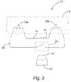
- the void 96 defined between the outer sleeve 70 and the lamp sleeve 52is configured to provide the lamp assembly with the desired conductive or insulative properties.
- this void 96can be evacuated to insulate the lamp from cold environments.
- the void 96can be filled with heavier gases, such as argon and neon, or fluids to conduct heat in hot environments. The conduction of heat from lamps in hot environments will help to protect the lamp from overheating and may also help to provide maximum intensity.
- the lamp assembly 10may also include a mechanism that permits the ballast to sense the presence of the lamp assembly 10 . This permits the ballast to power the primary (not shown) only when the lamp assembly 10 is installed.
- the sensing mechanismis not necessary in many applications, particularly in low-power applications, it does provide a more efficient design that conserves power, reduces heat build-up and protects the primary from certain types of damage associated with continuous operation.
- the lamp assembly 10includes a sensing magnet 60 and the ballast (not shown), or an associated control circuit, includes a reed switch (not shown) that is activated by the sensing magnet 60 . More preferably, when the lamp assembly 10 is installed, the sensing magnet 60 is positioned adjacent to reed switch (not shown).
- the magnetic field from the sensing magnet 60causes the reed switch 62 to close, thereby providing a signal to the ballast or control circuit that the lamp assembly 10 is in place.
- the sensing magnetis preferably mounted to the base 50 , but may be mounted in other locations as desired.
- the sensing magnet 60 and reed switchcan be replaced by a mechanical switch (not shown).
- a switchcan be disposed where it is mechanically closed by installation of the lamp assembly 10 .
- Another alternativeis to provide the lamp with a manually actuated on/off switch, for example, a toggle switch, that selectively turns the ballast on and off.
- the lamp circuit 12will now be described in connection with the type PL-S 38W UV lamp described above (See FIGS. 1 and 2 ).
- the lamp circuit 12generally includes a lamp 18 , a secondary 14 and a capacitor 16 .
- a schematic diagram of a lamp circuit 12is shown in FIG. 3 .
- the lamp circuit 12includes a single secondary 14 , preferably in the form of a coil of small diameter wire 22 .
- the precise characteristics of the secondary 14will vary from application to application as a function of the primary (not shown) and the load (e.g. the lamp).
- the wire 22is preferably conventional magnet or LITZ wire depending on the power settings and heat dissipation.
- the wireis preferably wrapped around the base 50 within the annular recess 80 , which provides the secondary 14 with a hollow core. If desired, the hollow core 24 can be replaced by other conventional cores.
- the type of wire, the number of turns of wire and the diameter of the core (and consequently the diameter of the turns of wire)will vary from application to application, depending on various factors such as the characteristics of the primary and the load of the lamp 18 .
- the inductance of the secondary 14is selected as a function of the operating frequency and the impedance of the load (i.e. the lamp) at the supplied power. More specifically, the inductance of the secondary 14 is determined by the following formula:
- the secondary 14is configured to receive power from a primary operating at approximately 100 kilohertz.
- the secondary 14includes 72 turns of wire and the primary includes 135 turns of wire.
- the secondary 14has a value of 196 microhenries at 100 kilohertz, having a reactance of approximately 123 ohms.
- the secondary 14is preferably located within the base 50 of the lamp assembly 10 .
- the diameter of the secondary 14is preferably selected to closely fit with the base 50 .
- the secondary 14is electrically connected to lamp 18 by leads 51 a - b.
- the secondary 14is preferably circular, it may vary in shape form from application to application.
- the secondarymay be square, oval, triangular, trapezoidal, hexagonal or even spherical.
- the secondaryis preferably positioned internally or externally concentric to the primary, or the two coils may be placed end to end.
- the capacitor 16is selected to provide optimum power factor correction given to the mechanical constraints, thereby providing resonance in the lamp circuit 12 .
- the power factoris preferably 0.90 or better, and more preferably 0.96 or better, but in some applications lower values may be acceptable. Without sufficient power factor correction, the reactive currents in the secondary will reflect back into the primary as a lower impedance load. This would cause a shift upward in operating power and current, as well as higher losses in the form of heat gain in the primary circuit. This effect is contrary to what one might initially expect but is in fact due to the inverse nature of reflected impedance within a series resonant primary circuit. Experience has revealed that reactive currents and losses in the primary increase very quickly at factors below 0.90.
- the capacitor 16is selected to have a reactance that is approximately equal to or slightly less than the resistive impedance of the lamp 18 and the reactive impedance of the secondary 14 when the lamp 18 is at its operating temperature.
- the reactance of the capacitoris selected as a function of the operating frequency and the impedance of the load (i.e. the lamp at the supplied power. More specifically, the reactance of the capacitor is selected in accordance with the following formula:
- the capacitor 16has a value of approximately 12.9 nanofarads (nf). This value will change in response to variations in the primary (not shown), secondary 14 and/or lamp 18 .
- the secondary and capacitor formulas presented aboveprovide a rough approximation of the desired capacitor and secondary reactance values.
- an iterative testing proceduremay be employed. This iterative testing may be required in some applications to provide the desire level of efficiency in the secondary circuit.
- the operating parameters of these designsinclude preheat, strike voltage, and operating current. All of these parameters can be configured through this tuning process along with changes in values of ratios, capacitance and inductance.
- the capacitor 16is preferably tuned to the secondary 14 and lamp 18 when the lamp 18 is at operating temperature
- the capacitor 16can alternatively be tuned to provide optimum efficiency at other times.
- the present inventioncan be employed to boost the circuit during start-up.
- the capacitoris selected to have a reactance that is approximately equal to the combined impedance of the secondary and the lamp at start-up temperature (rather than at operating temperature). This will increase the efficiency of the lamp circuit during start-up, permitting the use of a ballast with a lower current maximum.
- the lamp circuit 12preferably includes a conventional starter 35 (See FIG. 2 ), glow bulb or other equivalent mechanism. Starters and glow bulbs are well known and will therefore not be described in detail in this application.
- the conventional starteris replaced by a remotely actuatable switch, such as electromagnetic switch 34 (See FIG. 3 ).
- the electromagnetic switch 34is wired in series between the electrodes 36 a - b, thereby selectively permitting the switch 34 to close the circuit between the electrodes 36 a - b. When closed, the switch 34 permits current to flow directly through the electrodes 36 a - b, rather than through requiring it to arc through the gas.
- the electromagnetic switch 34is preferably arranged substantially perpendicular to the field of the primary so that the electromagnetic switch 34 is not actuated by the electromagnetic field of the primary. Instead, a separate coil 38 is positioned adjacent to the electromagnetic switch 34 where it can be charged to selectively close the switch 34 .
- a microprocessor 40preferably controls operation of the coil 38 and therefore the electromagnetic switch 34 .
- the microprocessor 40is programmed to charge the coil 38 for a fixed period of time each time that the lamp circuit is powered on. This closes the electromagnetic switch 34 shorting the electrodes 36 a - b together.
- the microprocessor 40can be replaced by a conventional one-shot timer circuit (not shown) that is configured to charge the coil for the desired period of time each time that the lamp is started.
- the configuration of the lamp assemblymay vary materially from application to application depending largely on the type of lamp and the associated power requirements.
- the present inventioncan be readily modified to permit use with a wide variety of existing lighting systems.
- the following alternative embodimentsdescribe a variety of alternative embodiments adapted for various uses. These alternative embodiments are intended to be illustrative of the wide adaptability of the present invention, and not intended to be exhaustive.
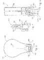
- the lamp assembly 110includes a glass sleeve 152 and a plastic base 150 .
- the glass sleeve 152is generally bulb shaped and includes an inwardly turned and generally cylindrical stem 132 .
- a secondary 114is mounted within the glass sleeve 152 about stem 132 .
- a filament 136is mounted to the secondary 114 extending upwardly into the bulbous portion of the glass sleeve 152 in a conventional manner.
- the base 150 in this embodimentis fitted to the outside of the glass sleeve 152 .
- the base 150is configured to be interfitted with a corresponding socket (not shown).
- the illustrated base 150is generally circular and includes an annular recess 156 configured to snap fit into a corresponding socket (not shown).
- the base 150also includes an upper flange 158 that provides a gripping edge for removing the lamp assembly 110 from a socket (not shown).
- the base 150may, however, take on a variety of different configurations to permit the lamp assembly 110 to mechanical connect to a variety of different sockets.
- the basemay be externally threaded.
- lamp assembly 110also preferably includes a sensing magnet 160 .
- the sensing magnet 160may be fitted into a corresponding retaining wall 162 in the bottom of base 150 .
- the sensing magnet 160functions with a magnetically actuated switch, such as a reed switch, to advise the primary or control circuit of the presence of the lamp assembly 110 .
- a magnetically actuated switchsuch as a reed switch
- the sensing magnet 160functions with a magnetically actuated switch, such as a reed switch, to advise the primary or control circuit of the presence of the lamp assembly 110 .
- the incandescent lamp assembly 110 ′can be configured to operate with a conventional universal base.
- the base 150 ′includes a pair of mounting pins 156 a - b that are configured to interlock with matching slots in a conventional universal base lamp socket (not shown).
- the lamp assembly 210generally includes a quartz sleeve 252 and a ceramic base 250 .
- the materials of the sleeve 252 and base 250are selected to withstand the particularly high temperature at which halogen lamps operate.
- the quartz sleeve 252is preferably fully sealed and does not include any penetrating elements, such as wires or other electrical connectors.
- a filament 236 , secondary 214 and capacitor 216are enclosed within the quartz sleeve 252 . In some applications, the capacitor 216 may not be necessary to provide an acceptable level of efficiency and may accordingly be eliminated.
- the lamp assembly 210further includes a heat reflector 258 disposed between the filament 236 and the secondary 214 .
- the base 250may include quarter turn threads 256 a - b that are threadedly interfitted within a corresponding socket (not shown).
- the base 250can be provided with alternative structure to facilitate installation in the socket.
- a sensing magnet 260is preferably mounted to the inside bottom surface of the base 250 .
- the quartz sleeve 252 ′is shortened to terminate just within the neck of the base 250 ′ (See FIG. 7 ).
- the secondary 214 ′is moved outside of the quartz sleeve 252 ′ and is positioned in the base 250 ′.
- the secondary 214 ′is isolated from the heat of the filament 236 ′.
- This embodimentmay also include a sensing magnet 260 ′.
- the baseis eliminated and the sensing magnet 260 ′′is moved into the interior of the sealed quartz sleeve 252 ′′.
- the quartz sleeve 252 ′′defines an annular recess 256 ′′ that extends entirely around the sleeve 252 ′′ to permit the lamp assembly 210 ′′ to be snap-fitted into a corresponding socket (not shown).
- the lamp assembly 310includes a base 350 that is disposed outside of the lamp sleeve 352 and the lamp assembly 310 does not include an outer sleeve.
- the lamp sleeve 352encloses the electrodes 336 a - b and the desired electric-discharge gas, for example, mercury vapor.
- the secondary 314 , capacitor 316 , any desired starter mechanism (such as a conventional starter or the magnetically actuated switch described above) and all electrical connectionsare contained inside the base 350 , but outside of the lamp sleeve 352 .
- the base 350is configured to corresponding with a conventional universal base, and includes a pair of mounting pins 356 a - b that interlock with matching slots in the lamp socket (not shown).
- the base 350may alternatively be configured to match with other socket configurations.
- a sensing magnet 360is preferably mounted in the base 350 .
- an outer sleeve(not shown) can be added to this lamp assembly 310 to enhance its protection from the environment. If included, the outer sleeve would preferably extend around the entire lamp assembly, except for the base 350 .
- the base 350would mounted to the exterior of the outer sleeve where it can be interfitted with a lamp socket.
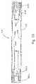
- the lamp assembly 410includes an elongated glass sleeve 452 and a pair of secondaries 414 a - b -one located at each end of the sleeve 452 .
- the power supplyis preferably configured to include two separate primaries (not shown) that separately power the two secondaries 414 a - b.
- the two primariesare disposed adjacent to the corresponding secondary 414 a - b. It is typical to evenly distribute the power between the coils 414 a - b, but is not strictly necessary.
- the secondary coils 414 a - bare set to opposite polarity with each primary and secondary combination being configured to sustain half of the voltage and current needed to power the lamp.
- the sleeve 452preferably includes an annular stem 432 a - b formed at each opposite end to receive the secondaries 414 a - b.
- An electrode 436 a - bis electrically connected to each secondary 414 a - b.
- a capacitor 416is connected in series between the two secondaries 414 a - b.
- the preferred method for calculating the value of the capacitors 416 a - b in this embodimentis to initially analyze the circuit as though only a single coil was going to be used in accordance with the methodology described above (in connection with the first disclosed embodiment). The value of the single capacitor of this hypothetical configuration is then halved to provide the value for each of the two capacitors 416 a - b of this embodiment.
- Optional end caps 420 a - b, preferably of aluminum,are fitted over opposite ends of the sleeve 452 .
- the lamp assembly 410may include a conventional started 435 as shown in FIG. 11 .
- conductors 498 a - bare required to extend between the two secondary coils 414 a - b.
- the conductors 498 a - bare preferably contained within the lamp sleeve 452 .
- magnetic switches 434 a - bor other remotely actuated switches, are used in place of a conventional starter.
- the lamp assembly 410 ′includes a separate switch 434 a - b that is mounted in series between each secondary coil 414 a - b′ and it's corresponding filament or electrode 436 a - b′. By closing the switches 434 a - b, the power from each secondary coil 414 a - b′ is supplied directly to its corresponding filament.
- only a single conductor 498 ′is required to extend between the secondary coils 414 a - b′.
- the capacitor 416 ′is connected in series along the conductors 498 ′.
- FIG. 13An alternative circuit for a dual-coil lamp assembly 410 ′′ is shown in FIG. 13 .
- each secondary coil 414 a - b′′includes a dedicated switch 434 a - b′′ and a dedicated capacitor 416 a - b′′.
- the lamp controlleris preferably configured to open and close the two switches 434 a - b′′ in unison.
- the preferred method for calculating the value of the capacitors 416 a - b′′is to initially analyze the circuit in accordance with the first disclosed embodiment as though only a single coil and single capacitor were going to be used.
- the value of the single capacitor of this hypothetical configurationis then halved to provide the value for each of the two capacitors 416 a - b′′ of this embodiment.
- the powermay not be evenly distributed between the two secondaries.
- the ratio between the value of the two capacitorsshould be equivalent to the ratio of the power between the two secondaries.
- FIG. 14Another alternative circuit for a dual-coil lamp 410 ′′′ is shown in FIG. 14 .
- the secondary coil 414 ′′′is connected to electrodes 436 a - b′′′ is provided.
- This circuitincludes a pair of conductors 498 a - b′′′ that extend between the coils.
- a conventional starter 435 ′′′ or other starter mechanism, such as magnetic switches,is included to start the lamp.
- the value of the capacitor 416 ′′′is preferably selected in accordance with the method of the first disclosed embodiment.
- FIGS. 15 and 16A further alternative embodiment showing the present invention adapted for use in a PL type fluorescent lamp is shown in FIGS. 15 and 16 .
- the entire lamp circuitis enclosed within the lamp sleeve 552 , and no outer sleeve is included.
- the lamp assembly 510includes a glass sleeve 552 having to interconnected legs 502 a - b.
- the lamp assembly 510may include any of the dual coil lamp circuits described above. For purposes of disclosure, this embodiment is described in connection with a lamp assembly 510 having a separate secondary 514 a - b mounted in the base of each leg 502 a - b.
- the two secondaries 514 a - bare preferably powered by a single primary (not shown) surrounding or adjacent to one end of the lamp assembly 510 .
- Each secondary 514 a - bis connected in series with an electrode 536 a - b, a capacitor 516 a - b and a magnetically actuated starter switch 534 a - b.
- the value of each capacitor 516 a - bis selected as described above is connection with the embodiment of FIG. 13 .
- This lamp assembly 510may also include a sensing magnet 560 .
- FIGS. 17 and 18An alternative lamp assembly 610 having an alternative sealing structure is shown in FIGS. 17 and 18 .
- the lamp assembly 610generally includes a locking ring 602 , an outer sleeve 670 , a lamp 618 and a base 650 .
- the locking ring 602 , outer sleeve 670 and base 650cooperate to seal the lamp assembly 610 .
- the base 650includes a cylindrical central portion 652 that is shaped to receive the secondary 614 and the lamp 618 . More specifically, the lamp 618 is mounted to a printed circuit board assembly (“PCBA”) 654 , which will preferably also support any capacitor or starter mechanism incorporated into the lamp assembly 610 .
- PCBAprinted circuit board assembly
- the lamp/PCBA combinationis mounted to the base 650 , for example, by fasteners or a snap-fit.
- the base 650also includes annular channel 656 that extends around the base 650 to receive the end of the outer sleeve 670 .
- An o-ring 604is fitted around the central portion 652 within the annular channel 656 .
- the base 650may include an annular rib (not shown) to prevent the o-ring 604 from riding up the central portion 652 . Once assembled, the o-ring 604 is disposed between the inner diameter of the outer sleeve 670 and the outer diameter of the central portion 652 of the base 650 .
- the o-ring 604not only provides an effective seal against water, but it also functions as a vibration damper that cushions vibrations between the lamp and the outer sleeve 670 .
- the outer sleeve 670is a generally cylindrical tube having a closed end and an open end. A bead 672 or other flange extends around the open end of the outer sleeve 670 .
- the outer sleeve 670is secured to the base 650 by the locking ring 602 .
- the locking ring 602is generally ring-shaped and is fitted over the outer sleeve 670 and the base 650 .
- the locking ring 602has a generally inverted L-shaped cross section with a radial leg 674 and an axial leg 676 .
- the radial leg 674engages the bead 672 and the axial leg 676 engages the outer surface of the base 650 .
- the locking ring 602 ′ and base 650 ′can be configured so that the axial leg 676 ′ is fitted within the annular channel 656 ′. In either case, the axial leg 676 or 676 ′ is secured to the base 650 or 650 ′ to lock the outer sleeve 670 in the annular channel 656 of the base 650 .
- the locking ring 602may be attached to the base 650 using various attachment methods.
- the locking ring 602may be sonic or heat welded to the base 650 .
- the lamp assembly 610 ′′′may include a locking ring 602 ′′ having a lower flange 678 (See FIG. 20 ) that permits the locking ring 602 ′ to be snap-fitted onto the base 650 ′, or the locking ring and base can includes threads (not shown) to permit the locking ring to be threaded to the base.
Landscapes
- Engineering & Computer Science (AREA)
- Health & Medical Sciences (AREA)
- Life Sciences & Earth Sciences (AREA)
- Power Engineering (AREA)
- Hydrology & Water Resources (AREA)
- Environmental & Geological Engineering (AREA)
- Water Supply & Treatment (AREA)
- Chemical & Material Sciences (AREA)
- Organic Chemistry (AREA)
- Public Health (AREA)
- Animal Behavior & Ethology (AREA)
- General Health & Medical Sciences (AREA)
- Epidemiology (AREA)
- Veterinary Medicine (AREA)
- Toxicology (AREA)
- Clinical Laboratory Science (AREA)
- General Engineering & Computer Science (AREA)
- Discharge Lamps And Accessories Thereof (AREA)
- Circuit Arrangements For Discharge Lamps (AREA)
- Arrangement Of Elements, Cooling, Sealing, Or The Like Of Lighting Devices (AREA)
- Circuit Arrangement For Electric Light Sources In General (AREA)
- Fastening Of Light Sources Or Lamp Holders (AREA)
- Connecting Device With Holders (AREA)
- Non-Portable Lighting Devices Or Systems Thereof (AREA)
- Led Devices (AREA)
Abstract
Description
The present invention is a continuation of U.S. application Ser. No. 10/,977,443, now U.S. Pat. No. 7,153,178, filed Oct. 29, 2004, which is a continuation of U.S. application Ser. No. 10/455,694, now U.S. Pat. No. 6,831,417, filed Jun. 5, 2003, which is a division of U.S. application Ser. No. 10/133,860, now U.S. Pat. No. 6,731,071, filed Apr. 26, 2002, which claims the benefit of U.S. Provisional Application No. 60/357,908, entitled Point of Use Water Treatment System, filed Feb. 19, 2002 and is a continuation-in-part of U.S. application Ser. No. 09/592,194 entitled Fluid Treatment System, which was filed on Jun. 12, 2000, now U.S. Pat. No. 6,436,299, which claims benefit of U.S. Provisional Application Ser. No. 60/140,159, entitled Water Treatment System Within Inductively Coupled Ballast, filed Jun. 21, 1999, and which claims the benefit of U.S. Provisional Application Ser. No. 60/140,090, entitled Point-Of-Use Water Treatment System, filed Jun. 21, 1999.
The present invention relates to lighting and more particularly to a lamp assembly for use in connection with inductively powered lighting.
Although not widely available, inductively coupled lighting systems are known. A conventional inductively coupled lighting system generally includes a primary circuit having a primary coil (or “primary”) that is driven by a power supply and a secondary circuit having a secondary coil (or “secondary”) that inductively receives power from the primary. Inductive couplings provide a number of advantages over conventional direct electrical connections. First, inductively coupled lamps are typically safer and easier to connect and disconnect than hardwired lamps. With direct electrical connections, it is generally necessary to manipulate electrical connectors when installing and removing the lamp assembly. This typically requires some effort and creates a risk of electrical shock. Often, the electrical connectors are at least partially exposed, thereby increasing the risk of electrical shock. Inductively coupled lamps, on the other hand, do not require the manipulation of any electrical connectors. Instead, the secondary of the lamp assembly simply needs to be placed adjacent to the primary to permit the supply of power to the lamp assembly. Second, the elimination of electrical connectors also increases the reliability of the system by eliminating the problems associated with conventional electrical connectors. For example, conventional electrical connectors are subject to corrosion and to wear. These problems are particularly acute in an outdoor setting where environmental conditions may subject the electrical connectors to moisture. With repeated use, mechanical connectors are also subject to wear and eventual failure. Third, inductively coupled lamps inherently provide a lower risk of an electrical hazard at the lamp assembly. As noted above, the lamp assembly is electrically separated from the power source. All power must be inductively passed from the power source to the lamp assembly. Because there is an intrinsic limit on the amount of power that can be inductively passed to the lamp assembly, the amount of power at the lamp assembly is limited and the risk of electrical hazard is reduced.
Although conventional inductively coupled lamps provide a number of important advantages over directly connected lamps, they do suffer significant drawbacks. An inductive coupling is inherently less efficient than a direct electrical connector. This is partly due to the power required to create and sustain the electromagnetic field. The primary inefficiencies in a conventional inductive coupling result from a poorly tuned circuit. These inefficiencies are manifest in increased heat gain and in noise created by vibration in the primary and secondary. The efficiency issues are exaggerated with higher power lighting applications. In addition, existing lamp circuits require precise alignment of the primary and secondary to provide any reasonable level of efficiency. This requires more precise tolerances and limits the configuration and layout of the lamp assembly and the overall lamp.
One of the largest reliability issues facing the lamp industry is caused by the penetration of the lamp sleeve by wires or other electrical conductors. Typically, the wires pass into the interior of the lamp through a glass stem. Because glass does not readily adhere to and seal around the wires, there is a material risk of lamp leakage at the point the wires penetrate the lamp. Although efforts have been made to optimize the seal, this remains a significant reliability concern.
With conventional inductively powered lamps, there are also reliability issues associated with exposure of the lamp circuit components to the environment, for example, water and moisture from the environment can damage circuit components. To address this concern, at least one inductively powered lighting system encloses the entire lamp assembly without a sealed enclosure. U.S. Pat. No. 5,264,997 to Hutchisson et al discloses a lamp that is mounted to a printed wiring board that is spaced from the secondary on a plurality of posts. The printed wiring board includes various electrical component required for operation of the inductive coupling. Separate shell and lens components are sealed together to form a leaktight enclosure around the lamp, the printed wiring board and the secondary. The shell is specially shaped to receive the secondary and to be interfitted with a socket containing the primary. Although the sealed enclosure provides improved protection from environmental conditions, it is relatively bulky and only provides light transmission in the direction of the lens.
As can be seen, there remains a need for an inductively coupled lamp assembly that is efficient, provides improved reliability in a variety of conditions and is easily adapted to many different lamp configurations.
The aforementioned problems are overcome by the present invention wherein a capacitor. The capacitor is connected in series with the lamp and the secondary, and is selected to have a resistance at the operating frequency that is approximately equal to or slightly less than the combined impedance of the lamp and the secondary at operating temperature. As a result, the lamp circuit operates at or near resonance. With electric-discharge lamps, the series capacitor also functions to limit the flow of current in the secondary circuit, precluding an uncontrolled increase in current that would otherwise occur with an electric discharge lamp.
In another aspect, the present invention provides an inductively powered lamp assembly in which the entire lamp assembly circuit is sealed within a transparent sleeve. Preferably, the entire lamp assembly circuit, including secondary and any associated capacitor is sealed within the sleeve of the lamp. In an alternative embodiment, the secondary and lamp, as well as any capacitor and starter device, are contained within a second closed plastic, Teflon, glass or quartz sleeve with no wires or other elements penetrating the sleeve. The void defined between the second sleeve and the lamp sleeve is preferably evacuated or filled with a functional gas to provide the desired level of heat conduction or insulation.
In a further aspect, the present invention provides a remotely actuated switch to provide preheat of electric-discharge lamp. The switch is provided to short the electrodes across the secondary for a specific period of time at lamp start-up. In addition this circuit may have a series resistor to help limit preheat current. In one embodiment, the switch is an electromagnetic switch that is preferably actuated by a magnetic field generated by a corresponding coil in a lamp control circuit.
The present invention provides a simple and inexpensive lamp assembly for use with inductively powered lighting. Because the lamp assembly operates at or near resonance, it has a high power factor and is highly efficient. This reduces power loss through heat build up and also provides for quiet operation of the inductive coupling—even in relatively high power applications. The efficiency of the secondary circuit demands less precise alignment between the primary and secondary, thereby permitting a greater degree of latitude in the layout and configuration of the lamp and the lamp assembly. The sealed sleeve provides the lamp circuit with improved protection from the environment without limiting the transmission of light from the lamp. Although with some light sources, the spectrums emitted may see losses based on the specific transmissive properties of the materials used in the sleeves, for example, some materials are not highly transmissive to UV light. The present invention allows functional gases to be entrapped within the sealed sleeve to increase or reduce the degree to which the lamp is isolated from the environment. Further, by enclosing the entire lamp circuit within the lamp sleeve, the need for wires or electrical leads that penetrate the sleeve can be eliminated. This greatly improves the reliability of the lamp while dramatically reducing manufacturing losses. Also, the electromagnetic switch of the present invention provides an inexpensive and reliable alternative to conventional starter circuits.
These and other objects, advantages, and features of the invention will be readily understood and appreciated by reference to the detailed description of the invention and the drawings.
A lamp assembly according to an embodiment of the present invention is shown inFIGS. 1 and 2 , and is generally designated10. For purposes of disclosure, the present invention is first described in connection with a conventional type PL-S 11 watt UV lamp converted for use at 38 watt, such as the type used in a water treatment device. Thelamp assembly 10 generally includes alamp circuit 12 and anouter sleeve 70. Thelamp circuit 12 includes a secondary14, acapacitor 16 and alamp 18, all connected in series (seeFIG. 3 ). The secondary14 inductively receives power fro the primary (not shown) of an associated ballast (not shown). Theseries capacitor 16 is specially tuned, as described in more detail below, so that the lamp circuit operates at resonance under specific operating conditions. Theentire lamp circuit 12 is fully enclosed within theouter sleeve 70, including the secondary14,capacitor 16 andlamp 18. At least a portion of theouter sleeve 70 is transparent and is not penetrated by electrical wires or other elements.
Although the following embodiment is described in connection with a type PL-S 38 watt UV lamp, the present invention is intended and well suited for use with lamps of various types and styles, including electric-discharge, incandescent, pulsed white light and light emitting diode (“LED”) lamps. This disclosure presents various alternative embodiments showing incandescent lamps and electric-discharge lamps. These examples are provided to illustrate the broad applicability and adaptability of the present invention, and not to provide any limit on the scope of the claims.
A wide variety of ballasts capable of powering the inductive lamp assembly of the present invention are well known to those skilled in the field. Accordingly, the ballast will not be described in detail. One ballast particularly well-suited for use with the type PL-S 38W UV lamp of the illustrated embodiment is disclosed in U.S. application Ser. No. 90/592,194 entitled “Fluid Treatment System,” which was filed on Jun. 12, 2000, which is incorporated herein by reference in its entirety. This ballast can be readily adapted to provide efficient operation of all of the disclosed embodiments of the present invention.
I. Lamp Configuration
As noted above, the type PL-S 38W UV lamp preferably includes anouter sleeve 70 that encloses thelamp circuit 12 to protect it from the environment (SeeFIGS. 1 and 2 ). Theouter sleeve 70 preferably includes amain body 90 and acap 92. Themain body 90 is a generally cylindrical tube having an open end and a closed end. After thelamp circuit 12 is installed within themain body 90, thecap 92 is sealed over the open end of themain body 90 to fully enclose thelamp circuit 12. Thelamp circuit 12 generally includes a secondary14, acapacitor 16 and alamp 18. As described below, thelamp circuit 12 may also include a starter35 (SeeFIG. 2 ). Thelamp 18 is a generally conventional PL-S type lamp having a quartz sleeve with two parallel legs72a-bthat are interconnected to cooperatively define achamber 28. Thechamber 28 is partially evacuated and contains the desired electric-discharge gas, such as mercury vapor. A stem32a-bis located at the base of each leg72a-b.A pair of conventional or custom designed electrodes26a-bare disposed within thechamber 28, one mounted atop each of the stems32a-b.In this embodiment, theouter sleeve 70 is preferably manufactured from quartz to permit the efficient passage of UV light. In non-UV applications, the outer sleeve may be manufactured from glass, Teflon or plastic, depending in part on the heat generated by the lamp and the operating environment of the lamp. For example, an alternative outer sleeve can be manufactured from a length of Teflon tubing having sealed opposite ends (not shown). The Teflon tubing can be fitted over the remainder of the lamp assembly, and its opposite ends can be crimped or otherwise sealed to close the Teflon sleeve. Preferably, each end of the Teflon tubing is folded back onto itself and crimped using heat and pressure.
Thelamp assembly 10 also includes abase 50 and asupport 86 that hold opposite ends thelamp 18 within theouter sleeve 70. Thebase 50 is generally cylindrical and dimensioned to be fitted closely within theouter sleeve 70. In addition to holding one end of thelamp 18, thebase 50 also receives the various electrical components of thelamp circuit 12. Thebase 50 defines anannular recess 80 to receive the windings of the secondary14, a pair of apertures82a-bto receive the base end of each leg72a-b,and a pair of voids84a-bto contain thecapacitor 16 and any desiredstarter 35. Thelamp assembly 10 may also include aheat reflector 58 disposed between the secondary and the electrodes36a-b.Theheat reflector 58 is preferably shaped to match the cross-sectional shape of the lamp sleeve52 at the point where it is mounted, and is preferably manufactured from a conventional reflective material, such as aluminum or aluminum foil on a suitable substrate. Thesupport 86 is generally disc-shaped and is dimensioned to be fitted closely within theouter sleeve 70. Thesupport 86 preferably includes atab 88 to be fictionally fitted between the legs72a-bof the quartz sleeve52. The precise design and configuration of thebase 50 andsupport 86 can vary among applications depending on the design and configuration of theouter sleeve 70 and the various components of thelamp circuit 12. Thebase 50 andsupport 86 are preferably manufactured from materials capable of withstanding high heat, such as ceramic or high temperature plastics.
In one embodiment, the void96 defined between theouter sleeve 70 and the lamp sleeve52 is configured to provide the lamp assembly with the desired conductive or insulative properties. For example, this void96 can be evacuated to insulate the lamp from cold environments. Alternatively, the void96 can be filled with heavier gases, such as argon and neon, or fluids to conduct heat in hot environments. The conduction of heat from lamps in hot environments will help to protect the lamp from overheating and may also help to provide maximum intensity.
In some applications, thelamp assembly 10 may also include a mechanism that permits the ballast to sense the presence of thelamp assembly 10. This permits the ballast to power the primary (not shown) only when thelamp assembly 10 is installed. Although the sensing mechanism is not necessary in many applications, particularly in low-power applications, it does provide a more efficient design that conserves power, reduces heat build-up and protects the primary from certain types of damage associated with continuous operation. In one embodiment, thelamp assembly 10 includes asensing magnet 60 and the ballast (not shown), or an associated control circuit, includes a reed switch (not shown) that is activated by thesensing magnet 60. More preferably, when thelamp assembly 10 is installed, thesensing magnet 60 is positioned adjacent to reed switch (not shown). The magnetic field from thesensing magnet 60 causes the reed switch62 to close, thereby providing a signal to the ballast or control circuit that thelamp assembly 10 is in place. The sensing magnet is preferably mounted to thebase 50, but may be mounted in other locations as desired. Alternatively, thesensing magnet 60 and reed switch (not shown) can be replaced by a mechanical switch (not shown). For example, a switch can be disposed where it is mechanically closed by installation of thelamp assembly 10. Another alternative is to provide the lamp with a manually actuated on/off switch, for example, a toggle switch, that selectively turns the ballast on and off.
II. Lamp Circuit
Thelamp circuit 12 will now be described in connection with the type PL-S 38W UV lamp described above (SeeFIGS. 1 and 2 ). As noted above, thelamp circuit 12 generally includes alamp 18, a secondary14 and acapacitor 16. A schematic diagram of alamp circuit 12 is shown inFIG. 3 . In this embodiment, thelamp circuit 12 includes a single secondary14, preferably in the form of a coil ofsmall diameter wire 22. The precise characteristics of the secondary14 will vary from application to application as a function of the primary (not shown) and the load (e.g. the lamp). Thewire 22 is preferably conventional magnet or LITZ wire depending on the power settings and heat dissipation. The wire is preferably wrapped around thebase 50 within theannular recess 80, which provides the secondary14 with a hollow core. If desired, thehollow core 24 can be replaced by other conventional cores. The type of wire, the number of turns of wire and the diameter of the core (and consequently the diameter of the turns of wire) will vary from application to application, depending on various factors such as the characteristics of the primary and the load of thelamp 18. The inductance of the secondary14 is selected as a function of the operating frequency and the impedance of the load (i.e. the lamp) at the supplied power. More specifically, the inductance of the secondary14 is determined by the following formula:
In the described 38 watt embodiment, the secondary14 is configured to receive power from a primary operating at approximately 100 kilohertz. The secondary14 includes 72 turns of wire and the primary includes 135 turns of wire. In the described 38 watt embodiment, the secondary14 has a value of 196 microhenries at 100 kilohertz, having a reactance of approximately 123 ohms. The secondary14 is preferably located within the
Thecapacitor 16 is selected to provide optimum power factor correction given to the mechanical constraints, thereby providing resonance in thelamp circuit 12. The power factor is preferably 0.90 or better, and more preferably 0.96 or better, but in some applications lower values may be acceptable. Without sufficient power factor correction, the reactive currents in the secondary will reflect back into the primary as a lower impedance load. This would cause a shift upward in operating power and current, as well as higher losses in the form of heat gain in the primary circuit. This effect is contrary to what one might initially expect but is in fact due to the inverse nature of reflected impedance within a series resonant primary circuit. Experience has revealed that reactive currents and losses in the primary increase very quickly at factors below 0.90. This can have a material adverse impact on efficiency, especially when it is considered that these losses are additive to the losses caused by coupling coefficient and dc resistances. In general, thecapacitor 16 is selected to have a reactance that is approximately equal to or slightly less than the resistive impedance of thelamp 18 and the reactive impedance of the secondary14 when thelamp 18 is at its operating temperature. Like the inductance of the secondary14, the reactance of the capacitor is selected as a function of the operating frequency and the impedance of the load (i.e. the lamp at the supplied power. More specifically, the reactance of the capacitor is selected in accordance with the following formula:
At this reactance, the
The secondary and capacitor formulas presented above provide a rough approximation of the desired capacitor and secondary reactance values. To provide more refined values (and thereby fine-tune the power factor, current limiting effect, and overall operating parameters), an iterative testing procedure may be employed. This iterative testing may be required in some applications to provide the desire level of efficiency in the secondary circuit. The operating parameters of these designs include preheat, strike voltage, and operating current. All of these parameters can be configured through this tuning process along with changes in values of ratios, capacitance and inductance.
Although thecapacitor 16 is preferably tuned to the secondary14 andlamp 18 when thelamp 18 is at operating temperature, thecapacitor 16 can alternatively be tuned to provide optimum efficiency at other times. For example, in electric-discharge lamps where greater current is required to start the lamp, the present invention can be employed to boost the circuit during start-up. In such applications, the capacitor is selected to have a reactance that is approximately equal to the combined impedance of the secondary and the lamp at start-up temperature (rather than at operating temperature). This will increase the efficiency of the lamp circuit during start-up, permitting the use of a ballast with a lower current maximum.
Given the nature of plasma, electric-discharge lamps attempt to maintain voltage at a substantially constant inherent voltage. As a result, if the secondary14 generates voltage in excess of the inherent voltage of the lamp, the lamp will attempt to consume the excess power. Because the resistance of in an electric-discharge lamp decreases in response to the flow of current, the lamp has the potential to drawing increasingly more current until the circuit limits or self-destructs. This concern is addressed by thecapacitor 16, which functions to limit the current supplied to the lamp. The current limiting function is an inherent characteristic of a capacitor. It has been determined that the capacitor value required to place the secondary circuit at resonance is approximately equal to the capacitor value needed to provide appropriate current limiting. Accordingly, it has been determined that the current limiting function is achieved in the present invention by selecting a capacitor value appropriate to provide unity power factor.
When the present invention is incorporated into an electric-discharge lamp assembly, thelamp circuit 12 preferably includes a conventional starter35 (SeeFIG. 2 ), glow bulb or other equivalent mechanism. Starters and glow bulbs are well known and will therefore not be described in detail in this application. In one embodiment of an electric-discharge lamp assembly, the conventional starter is replaced by a remotely actuatable switch, such as electromagnetic switch34 (SeeFIG. 3 ). Theelectromagnetic switch 34 is wired in series between the electrodes36a-b,thereby selectively permitting theswitch 34 to close the circuit between the electrodes36a-b.When closed, theswitch 34 permits current to flow directly through the electrodes36a-b,rather than through requiring it to arc through the gas. As a result, when theswitch 34 is closed, the electrodes36a-bare rapidly heated. Theelectromagnetic switch 34 is preferably arranged substantially perpendicular to the field of the primary so that theelectromagnetic switch 34 is not actuated by the electromagnetic field of the primary. Instead, aseparate coil 38 is positioned adjacent to theelectromagnetic switch 34 where it can be charged to selectively close theswitch 34. Amicroprocessor 40 preferably controls operation of thecoil 38 and therefore theelectromagnetic switch 34. Themicroprocessor 40 is programmed to charge thecoil 38 for a fixed period of time each time that the lamp circuit is powered on. This closes theelectromagnetic switch 34 shorting the electrodes36a-btogether. Alternatively, themicroprocessor 40 can be replaced by a conventional one-shot timer circuit (not shown) that is configured to charge the coil for the desired period of time each time that the lamp is started.
III. Alternative Embodiments
The configuration of the lamp assembly may vary materially from application to application depending largely on the type of lamp and the associated power requirements. The present invention can be readily modified to permit use with a wide variety of existing lighting systems. The following alternative embodiments describe a variety of alternative embodiments adapted for various uses. These alternative embodiments are intended to be illustrative of the wide adaptability of the present invention, and not intended to be exhaustive.
An alternative embodiment showing the present invention incorporated into an incandescent lamp is shown inFIG. 4 . In this embodiment, thelamp assembly 110 includes aglass sleeve 152 and aplastic base 150. Theglass sleeve 152 is generally bulb shaped and includes an inwardly turned and generallycylindrical stem 132. A secondary114 is mounted within theglass sleeve 152 aboutstem 132. Afilament 136 is mounted to the secondary114 extending upwardly into the bulbous portion of theglass sleeve 152 in a conventional manner. Unlike the embodiment described above, the base150 in this embodiment is fitted to the outside of theglass sleeve 152. Thebase 150 is configured to be interfitted with a corresponding socket (not shown). The illustratedbase 150 is generally circular and includes anannular recess 156 configured to snap fit into a corresponding socket (not shown). The base150 also includes anupper flange 158 that provides a gripping edge for removing thelamp assembly 110 from a socket (not shown). The base150 may, however, take on a variety of different configurations to permit thelamp assembly 110 to mechanical connect to a variety of different sockets. For example, the base may be externally threaded. As illustrated,lamp assembly 110 also preferably includes asensing magnet 160. Thesensing magnet 160 may be fitted into acorresponding retaining wall 162 in the bottom ofbase 150. As described above, thesensing magnet 160 functions with a magnetically actuated switch, such as a reed switch, to advise the primary or control circuit of the presence of thelamp assembly 110. This permits the primary to be powered only when alamp assembly 110 is in place. As shown inFIG. 5 , theincandescent lamp assembly 110′ can be configured to operate with a conventional universal base. In this embodiment, the base150′ includes a pair of mountingpins 156a-bthat are configured to interlock with matching slots in a conventional universal base lamp socket (not shown).
An alternative embodiment showing the present invention incorporated into a halogen lamp is shown inFIG. 6 . In this embodiment, thelamp assembly 210 generally includes aquartz sleeve 252 and aceramic base 250. The materials of thesleeve 252 andbase 250 are selected to withstand the particularly high temperature at which halogen lamps operate. Thequartz sleeve 252 is preferably fully sealed and does not include any penetrating elements, such as wires or other electrical connectors. Afilament 236, secondary214 andcapacitor 216 are enclosed within thequartz sleeve 252. In some applications, thecapacitor 216 may not be necessary to provide an acceptable level of efficiency and may accordingly be eliminated. Thelamp assembly 210 further includes aheat reflector 258 disposed between thefilament 236 and the secondary214. The base250 may include quarter turnthreads 256a-bthat are threadedly interfitted within a corresponding socket (not shown). The base250 can be provided with alternative structure to facilitate installation in the socket. Asensing magnet 260 is preferably mounted to the inside bottom surface of thebase 250.
In an alternativehalogen lamp assembly 210′, thequartz sleeve 252′ is shortened to terminate just within the neck of the base250′ (SeeFIG. 7 ). The secondary214′ is moved outside of thequartz sleeve 252′ and is positioned in the base250′. In this embodiment, the secondary214′ is isolated from the heat of thefilament 236′. This embodiment may also include asensing magnet 260′.
In another alternativehalogen lamp assembly 210″, the base is eliminated and thesensing magnet 260″is moved into the interior of the sealedquartz sleeve 252″. As shown inFIG. 8 , thequartz sleeve 252″ defines anannular recess 256″ that extends entirely around thesleeve 252″ to permit thelamp assembly 210″ to be snap-fitted into a corresponding socket (not shown).
Another alternative embodiment is shown inFIG. 9 . In this embodiment, thelamp assembly 310 includes a base350 that is disposed outside of thelamp sleeve 352 and thelamp assembly 310 does not include an outer sleeve. Thelamp sleeve 352 encloses the electrodes336a-band the desired electric-discharge gas, for example, mercury vapor. The secondary314,capacitor 316, any desired starter mechanism (such as a conventional starter or the magnetically actuated switch described above) and all electrical connections are contained inside thebase 350, but outside of thelamp sleeve 352. Thebase 350 is configured to corresponding with a conventional universal base, and includes a pair of mounting pins356a-bthat interlock with matching slots in the lamp socket (not shown). The base350 may alternatively be configured to match with other socket configurations. A sensing magnet360 is preferably mounted in thebase 350. If desired, an outer sleeve (not shown) can be added to thislamp assembly 310 to enhance its protection from the environment. If included, the outer sleeve would preferably extend around the entire lamp assembly, except for thebase 350. The base350 would mounted to the exterior of the outer sleeve where it can be interfitted with a lamp socket.
An alternative embodiment showing the present invention incorporated into a type T5 or T8 fluorescent lamp is shown inFIGS. 10 and 11 . Thelamp assembly 410 includes anelongated glass sleeve 452 and a pair ofsecondaries 414a-b-one located at each end of thesleeve 452. Given the different physical location of the twosecondaries 414a-b,the power supply is preferably configured to include two separate primaries (not shown) that separately power the twosecondaries 414a-b.The two primaries are disposed adjacent to the corresponding secondary414a-b.It is typical to evenly distribute the power between thecoils 414a-b,but is not strictly necessary. Preferably, thesecondary coils 414a-bare set to opposite polarity with each primary and secondary combination being configured to sustain half of the voltage and current needed to power the lamp. Thesleeve 452 preferably includes an annular stem432a-bformed at each opposite end to receive thesecondaries 414a-b.An electrode436a-bis electrically connected to each secondary414a-b.Acapacitor 416 is connected in series between the twosecondaries 414a-b.The preferred method for calculating the value of thecapacitors 416a-bin this embodiment is to initially analyze the circuit as though only a single coil was going to be used in accordance with the methodology described above (in connection with the first disclosed embodiment). The value of the single capacitor of this hypothetical configuration is then halved to provide the value for each of the twocapacitors 416a-bof this embodiment. Optional end caps420a-b,preferably of aluminum, are fitted over opposite ends of thesleeve 452. Thelamp assembly 410 may include a conventional started435 as shown inFIG. 11 . In this embodiment,conductors 498a-bare required to extend between the twosecondary coils 414a-b.Theconductors 498a-bare preferably contained within thelamp sleeve 452. As an alternative, magnetic switches434a-b,or other remotely actuated switches, are used in place of a conventional starter. As shown inFIG. 12 , thelamp assembly 410′ includes a separate switch434a-bthat is mounted in series between eachsecondary coil 414a-b′ and it's corresponding filament or electrode436a-b′.By closing the switches434a-b,the power from eachsecondary coil 414a-b′ is supplied directly to its corresponding filament. In this embodiment, only asingle conductor 498′ is required to extend between thesecondary coils 414a-b′.Thecapacitor 416′ is connected in series along theconductors 498′.
An alternative circuit for a dual-coil lamp assembly 410″ is shown inFIG. 13 . In this circuit, no conductors are required to extend between the twosecondary coils 414a-b′.Instead, eachsecondary coil 414a-b″ includes a dedicated switch434a-b″ and adedicated capacitor 416a-b″.The lamp controller is preferably configured to open and close the two switches434a-b″ in unison. The preferred method for calculating the value of thecapacitors 416a-b″ is to initially analyze the circuit in accordance with the first disclosed embodiment as though only a single coil and single capacitor were going to be used. The value of the single capacitor of this hypothetical configuration is then halved to provide the value for each of the twocapacitors 416a-b″ of this embodiment. In some applications, the power may not be evenly distributed between the two secondaries. In such applications, the ratio between the value of the two capacitors should be equivalent to the ratio of the power between the two secondaries.
Another alternative circuit for a dual-coil lamp 410′″ is shown inFIG. 14 . In this alternative, only a singlesecondary coil 414′″ is provided. Thesecondary coil 414′″ is connected to electrodes436a-b′″ is provided. This circuit includes a pair ofconductors 498a-b′″ that extend between the coils. Aconventional starter 435′″ or other starter mechanism, such as magnetic switches, is included to start the lamp. In this embodiment, the value of thecapacitor 416′″ is preferably selected in accordance with the method of the first disclosed embodiment.
A further alternative embodiment showing the present invention adapted for use in a PL type fluorescent lamp is shown inFIGS. 15 and 16 . In this embodiment, the entire lamp circuit is enclosed within thelamp sleeve 552, and no outer sleeve is included. As illustrated, thelamp assembly 510 includes aglass sleeve 552 having to interconnected legs502a-b.Thelamp assembly 510 may include any of the dual coil lamp circuits described above. For purposes of disclosure, this embodiment is described in connection with alamp assembly 510 having a separate secondary514a-bmounted in the base of each leg502a-b.The twosecondaries 514a-bare preferably powered by a single primary (not shown) surrounding or adjacent to one end of thelamp assembly 510. Each secondary514a-bis connected in series with an electrode536a-b,a capacitor516a-band a magnetically actuated starter switch534a-b.The value of each capacitor516a-bis selected as described above is connection with the embodiment ofFIG. 13 . Thislamp assembly 510 may also include asensing magnet 560.
Analternative lamp assembly 610 having an alternative sealing structure is shown inFIGS. 17 and 18 . As shown in the exploded view ofFIG. 17 , thelamp assembly 610 generally includes alocking ring 602, anouter sleeve 670, alamp 618 and abase 650. Thelocking ring 602,outer sleeve 670 andbase 650 cooperate to seal thelamp assembly 610. As perhaps best shown inFIG. 18 , thebase 650 includes a cylindricalcentral portion 652 that is shaped to receive the secondary614 and thelamp 618. More specifically, thelamp 618 is mounted to a printed circuit board assembly (“PCBA”)654, which will preferably also support any capacitor or starter mechanism incorporated into thelamp assembly 610. The lamp/PCBA combination is mounted to thebase 650, for example, by fasteners or a snap-fit. The base650 also includesannular channel 656 that extends around thebase 650 to receive the end of theouter sleeve 670. An o-ring 604 is fitted around thecentral portion 652 within theannular channel 656. The base650 may include an annular rib (not shown) to prevent the o-ring 604 from riding up thecentral portion 652. Once assembled, the o-ring 604 is disposed between the inner diameter of theouter sleeve 670 and the outer diameter of thecentral portion 652 of thebase 650. In this position, the o-ring 604 not only provides an effective seal against water, but it also functions as a vibration damper that cushions vibrations between the lamp and theouter sleeve 670. Theouter sleeve 670 is a generally cylindrical tube having a closed end and an open end. Abead 672 or other flange extends around the open end of theouter sleeve 670. Theouter sleeve 670 is secured to thebase 650 by the lockingring 602. Thelocking ring 602 is generally ring-shaped and is fitted over theouter sleeve 670 and thebase 650. Thelocking ring 602 has a generally inverted L-shaped cross section with aradial leg 674 and anaxial leg 676. Theradial leg 674 engages thebead 672 and theaxial leg 676 engages the outer surface of thebase 650. Alternatively, as shown inFIG. 19 , thelocking ring 602′ andbase 650′ can be configured so that theaxial leg 676′ is fitted within theannular channel 656′. In either case, theaxial leg outer sleeve 670 in theannular channel 656 of thebase 650. Thelocking ring 602 may be attached to the base650 using various attachment methods. For example, thelocking ring 602 may be sonic or heat welded to thebase 650. Alternatively, thelamp assembly 610′″ may include alocking ring 602″ having a lower flange678 (SeeFIG. 20 ) that permits thelocking ring 602′ to be snap-fitted onto the base650′, or the locking ring and base can includes threads (not shown) to permit the locking ring to be threaded to the base.
The above description is that of various embodiments of the invention. Various alterations and changes can be made without departing from the spirit and broader aspects of the invention as defined in the appended claims, which are to be interpreted in accordance with the principles of patent law including the doctrine of equivalents. Any reference to claim elements in the singular, for example, using the articles □a,□ □an,□ □the□ or □said,□ is not to be construed as limiting the element to the singular.
Claims (8)
1. An inductively powered secondary assembly comprising:
an inductive secondary to receive power from an inductive primary, the inductive secondary having a reactance;
a load disposed in series with the inductive secondary, the load having an impedance; and
a capacitor disposed in series with the inductive secondary and the load, the capacitor selected to have a reactance that is substantially equal to or slightly less than the sum of the impedance of the load and the reactance of the inductive secondary, whereby the load and the inductive secondary operate substantially at resonance.
2. The inductively powered secondary assembly ofclaim 1 wherein said inductive secondary is a coil of LITZ wire.
3. The inductively powered secondary assembly ofclaim 2 further including a sleeve surrounding and fully enclosing said inductive secondary, said load and said capacitor, said sleeve being unpenetrated.
4. The inductively powered secondary assembly ofclaim 1 wherein said inductive secondary is a coil of magnetic wire.
5. An inducively powered secondary assembly comprising:
an inductive secondary to receive power from an inductive primary, the inductive secondary having a reactance;
a load disposed in series with the inductive secondary, the load having an impedance that is substantially equal to the reactance of the inductive secondary; and
a capacitor disposed in series with the inductive secondary and the load, the capacitor selected to have a reactance that is substantially equal to or slightly less than the sum of the impedance of the load and the reactance of the inductive secondary, whereby the load and the inductive secondary operate substantially at resonance.
6. The inductively powered secondary assembly ofclaim 5 wherein said inductive secondary is a coil of LITZ wire.
7. The inductively powered secondary assembly ofclaim 6 further including a sleeve surrounding and fully enclosing said inductive secondary, said load and said capacitor, said sleeve being unpenetrated.
8. The inductively powered secondary assembly ofclaim 5 wherein said inductive secondary is a coil of magnetic wire.
Priority Applications (1)
| Application Number | Priority Date | Filing Date | Title |
|---|---|---|---|
| US11/558,684US7474058B2 (en) | 1999-06-21 | 2006-11-10 | Inductively powered secondary assembly |
Applications Claiming Priority (8)
| Application Number | Priority Date | Filing Date | Title |
|---|---|---|---|
| US14015999P | 1999-06-21 | 1999-06-21 | |
| US14009099P | 1999-06-21 | 1999-06-21 | |
| US09/592,194US6436299B1 (en) | 1999-06-21 | 2000-06-12 | Water treatment system with an inductively coupled ballast |
| US35790802P | 2002-02-19 | 2002-02-19 | |
| US10/133,860US6731071B2 (en) | 1999-06-21 | 2002-04-26 | Inductively powered lamp assembly |
| US10/455,694US6831417B2 (en) | 1999-06-21 | 2003-06-05 | Method of manufacturing a lamp assembly |
| US10/977,443US7153178B2 (en) | 1999-06-21 | 2004-10-29 | Method of manufacturing a lamp assembly |
| US11/558,684US7474058B2 (en) | 1999-06-21 | 2006-11-10 | Inductively powered secondary assembly |
Related Parent Applications (1)
| Application Number | Title | Priority Date | Filing Date |
|---|---|---|---|
| US10/977,443ContinuationUS7153178B2 (en) | 1999-06-21 | 2004-10-29 | Method of manufacturing a lamp assembly |
Publications (2)
| Publication Number | Publication Date |
|---|---|
| US20070205730A1 US20070205730A1 (en) | 2007-09-06 |
| US7474058B2true US7474058B2 (en) | 2009-01-06 |
Family
ID=29249078
Family Applications (6)
| Application Number | Title | Priority Date | Filing Date |
|---|---|---|---|
| US10/133,860Expired - LifetimeUS6731071B2 (en) | 1999-06-21 | 2002-04-26 | Inductively powered lamp assembly |
| US10/455,694Expired - LifetimeUS6831417B2 (en) | 1999-06-21 | 2003-06-05 | Method of manufacturing a lamp assembly |
| US10/455,502Expired - Fee RelatedUS6812645B2 (en) | 1999-06-21 | 2003-06-05 | Inductively powered lamp assembly |
| US10/781,401Expired - LifetimeUS6917163B2 (en) | 2000-06-12 | 2004-02-18 | Inductively powered lamp assembly |
| US10/977,443Expired - LifetimeUS7153178B2 (en) | 1999-06-21 | 2004-10-29 | Method of manufacturing a lamp assembly |
| US11/558,684Expired - LifetimeUS7474058B2 (en) | 1999-06-21 | 2006-11-10 | Inductively powered secondary assembly |
Family Applications Before (5)
| Application Number | Title | Priority Date | Filing Date |
|---|---|---|---|
| US10/133,860Expired - LifetimeUS6731071B2 (en) | 1999-06-21 | 2002-04-26 | Inductively powered lamp assembly |
| US10/455,694Expired - LifetimeUS6831417B2 (en) | 1999-06-21 | 2003-06-05 | Method of manufacturing a lamp assembly |
| US10/455,502Expired - Fee RelatedUS6812645B2 (en) | 1999-06-21 | 2003-06-05 | Inductively powered lamp assembly |
| US10/781,401Expired - LifetimeUS6917163B2 (en) | 2000-06-12 | 2004-02-18 | Inductively powered lamp assembly |
| US10/977,443Expired - LifetimeUS7153178B2 (en) | 1999-06-21 | 2004-10-29 | Method of manufacturing a lamp assembly |
Country Status (12)
| Country | Link |
|---|---|
| US (6) | US6731071B2 (en) |
| EP (4) | EP1502479B1 (en) |
| JP (5) | JP4782415B2 (en) |
| KR (4) | KR100695385B1 (en) |
| CN (5) | CN1631060B (en) |
| AT (4) | ATE528970T1 (en) |
| AU (1) | AU2002259342A1 (en) |
| CA (3) | CA2771058C (en) |
| MY (4) | MY135436A (en) |
| RU (1) | RU2292130C2 (en) |
| TW (1) | TW576905B (en) |
| WO (1) | WO2003092329A2 (en) |
Cited By (116)
| Publication number | Priority date | Publication date | Assignee | Title |
|---|---|---|---|---|
| US20070222542A1 (en)* | 2005-07-12 | 2007-09-27 | Joannopoulos John D | Wireless non-radiative energy transfer |
| US20070285619A1 (en)* | 2006-06-09 | 2007-12-13 | Hiroyuki Aoki | Fundus Observation Device, An Ophthalmologic Image Processing Unit, An Ophthalmologic Image Processing Program, And An Ophthalmologic Image Processing Method |
| US20080164817A1 (en)* | 2007-01-08 | 2008-07-10 | Access Business Group International Llc | Inductively-powered gas discharge lamp circuit |
| US20080278264A1 (en)* | 2005-07-12 | 2008-11-13 | Aristeidis Karalis | Wireless energy transfer |
| US20090284083A1 (en)* | 2008-05-14 | 2009-11-19 | Aristeidis Karalis | Wireless energy transfer, including interference enhancement |
| US20100109445A1 (en)* | 2008-09-27 | 2010-05-06 | Kurs Andre B | Wireless energy transfer systems |
| US20100148589A1 (en)* | 2008-10-01 | 2010-06-17 | Hamam Rafif E | Efficient near-field wireless energy transfer using adiabatic system variations |
| US20100164298A1 (en)* | 2008-09-27 | 2010-07-01 | Aristeidis Karalis | Wireless energy transfer using magnetic materials to shape field and reduce loss |
| US20100164296A1 (en)* | 2008-09-27 | 2010-07-01 | Kurs Andre B | Wireless energy transfer using variable size resonators and system monitoring |
| US20100164297A1 (en)* | 2008-09-27 | 2010-07-01 | Kurs Andre B | Wireless energy transfer using conducting surfaces to shape fields and reduce loss |
| US20100171368A1 (en)* | 2008-09-27 | 2010-07-08 | Schatz David A | Wireless energy transfer with frequency hopping |
| US20100181845A1 (en)* | 2008-09-27 | 2010-07-22 | Ron Fiorello | Temperature compensation in a wireless transfer system |
| US20100201203A1 (en)* | 2008-09-27 | 2010-08-12 | Schatz David A | Wireless energy transfer with feedback control for lighting applications |
| US20100219694A1 (en)* | 2008-09-27 | 2010-09-02 | Kurs Andre B | Wireless energy transfer in lossy environments |
| US20100231340A1 (en)* | 2008-09-27 | 2010-09-16 | Ron Fiorello | Wireless energy transfer resonator enclosures |
| US20100259108A1 (en)* | 2008-09-27 | 2010-10-14 | Giler Eric R | Wireless energy transfer using repeater resonators |
| US20100264747A1 (en)* | 2008-09-27 | 2010-10-21 | Hall Katherine L | Wireless energy transfer converters |
| US20100277121A1 (en)* | 2008-09-27 | 2010-11-04 | Hall Katherine L | Wireless energy transfer between a source and a vehicle |
| US20100308939A1 (en)* | 2008-09-27 | 2010-12-09 | Kurs Andre B | Integrated resonator-shield structures |
| US20110043047A1 (en)* | 2008-09-27 | 2011-02-24 | Aristeidis Karalis | Wireless energy transfer using field shaping to reduce loss |
| US20110043049A1 (en)* | 2008-09-27 | 2011-02-24 | Aristeidis Karalis | Wireless energy transfer with high-q resonators using field shaping to improve k |
| US20110074346A1 (en)* | 2009-09-25 | 2011-03-31 | Hall Katherine L | Vehicle charger safety system and method |
| US20110121920A1 (en)* | 2008-09-27 | 2011-05-26 | Kurs Andre B | Wireless energy transfer resonator thermal management |
| US20110193416A1 (en)* | 2008-09-27 | 2011-08-11 | Campanella Andrew J | Tunable wireless energy transfer systems |
| US20110214676A1 (en)* | 2009-09-03 | 2011-09-08 | Breathe Technologies, Inc. | Methods, systems and devices for non-invasive ventilation including a non-sealing ventilation interface with an entrainment port and/or pressure feature |
| US8400017B2 (en) | 2008-09-27 | 2013-03-19 | Witricity Corporation | Wireless energy transfer for computer peripheral applications |
| US8410636B2 (en) | 2008-09-27 | 2013-04-02 | Witricity Corporation | Low AC resistance conductor designs |
| US8441154B2 (en) | 2008-09-27 | 2013-05-14 | Witricity Corporation | Multi-resonator wireless energy transfer for exterior lighting |
| US8461721B2 (en) | 2008-09-27 | 2013-06-11 | Witricity Corporation | Wireless energy transfer using object positioning for low loss |
| US8461722B2 (en) | 2008-09-27 | 2013-06-11 | Witricity Corporation | Wireless energy transfer using conducting surfaces to shape field and improve K |
| US8466583B2 (en) | 2008-09-27 | 2013-06-18 | Witricity Corporation | Tunable wireless energy transfer for outdoor lighting applications |
| US8471410B2 (en) | 2008-09-27 | 2013-06-25 | Witricity Corporation | Wireless energy transfer over distance using field shaping to improve the coupling factor |
| US8476788B2 (en) | 2008-09-27 | 2013-07-02 | Witricity Corporation | Wireless energy transfer with high-Q resonators using field shaping to improve K |
| US8487480B1 (en) | 2008-09-27 | 2013-07-16 | Witricity Corporation | Wireless energy transfer resonator kit |
| US8569914B2 (en) | 2008-09-27 | 2013-10-29 | Witricity Corporation | Wireless energy transfer using object positioning for improved k |
| US8587153B2 (en) | 2008-09-27 | 2013-11-19 | Witricity Corporation | Wireless energy transfer using high Q resonators for lighting applications |
| US8598743B2 (en) | 2008-09-27 | 2013-12-03 | Witricity Corporation | Resonator arrays for wireless energy transfer |
| US8629578B2 (en) | 2008-09-27 | 2014-01-14 | Witricity Corporation | Wireless energy transfer systems |
| US8667452B2 (en) | 2011-11-04 | 2014-03-04 | Witricity Corporation | Wireless energy transfer modeling tool |
| US8669676B2 (en) | 2008-09-27 | 2014-03-11 | Witricity Corporation | Wireless energy transfer across variable distances using field shaping with magnetic materials to improve the coupling factor |
| US8686598B2 (en) | 2008-09-27 | 2014-04-01 | Witricity Corporation | Wireless energy transfer for supplying power and heat to a device |
| US8729737B2 (en) | 2008-09-27 | 2014-05-20 | Witricity Corporation | Wireless energy transfer using repeater resonators |
| US8805530B2 (en) | 2007-06-01 | 2014-08-12 | Witricity Corporation | Power generation for implantable devices |
| US8847548B2 (en) | 2008-09-27 | 2014-09-30 | Witricity Corporation | Wireless energy transfer for implantable devices |
| US8901778B2 (en) | 2008-09-27 | 2014-12-02 | Witricity Corporation | Wireless energy transfer with variable size resonators for implanted medical devices |
| US8901779B2 (en) | 2008-09-27 | 2014-12-02 | Witricity Corporation | Wireless energy transfer with resonator arrays for medical applications |
| US8907531B2 (en) | 2008-09-27 | 2014-12-09 | Witricity Corporation | Wireless energy transfer with variable size resonators for medical applications |
| US8912687B2 (en) | 2008-09-27 | 2014-12-16 | Witricity Corporation | Secure wireless energy transfer for vehicle applications |
| US8922066B2 (en) | 2008-09-27 | 2014-12-30 | Witricity Corporation | Wireless energy transfer with multi resonator arrays for vehicle applications |
| US8928276B2 (en) | 2008-09-27 | 2015-01-06 | Witricity Corporation | Integrated repeaters for cell phone applications |
| US8933594B2 (en) | 2008-09-27 | 2015-01-13 | Witricity Corporation | Wireless energy transfer for vehicles |
| US8937408B2 (en) | 2008-09-27 | 2015-01-20 | Witricity Corporation | Wireless energy transfer for medical applications |
| US8946938B2 (en) | 2008-09-27 | 2015-02-03 | Witricity Corporation | Safety systems for wireless energy transfer in vehicle applications |
| US8957549B2 (en) | 2008-09-27 | 2015-02-17 | Witricity Corporation | Tunable wireless energy transfer for in-vehicle applications |
| US8963488B2 (en) | 2008-09-27 | 2015-02-24 | Witricity Corporation | Position insensitive wireless charging |
| US9035499B2 (en) | 2008-09-27 | 2015-05-19 | Witricity Corporation | Wireless energy transfer for photovoltaic panels |
| US9065423B2 (en) | 2008-09-27 | 2015-06-23 | Witricity Corporation | Wireless energy distribution system |
| US9093853B2 (en) | 2008-09-27 | 2015-07-28 | Witricity Corporation | Flexible resonator attachment |
| US9106203B2 (en) | 2008-09-27 | 2015-08-11 | Witricity Corporation | Secure wireless energy transfer in medical applications |
| US9105959B2 (en) | 2008-09-27 | 2015-08-11 | Witricity Corporation | Resonator enclosure |
| US9160203B2 (en) | 2008-09-27 | 2015-10-13 | Witricity Corporation | Wireless powered television |
| US9246336B2 (en) | 2008-09-27 | 2016-01-26 | Witricity Corporation | Resonator optimizations for wireless energy transfer |
| US9287607B2 (en) | 2012-07-31 | 2016-03-15 | Witricity Corporation | Resonator fine tuning |
| US9306635B2 (en) | 2012-01-26 | 2016-04-05 | Witricity Corporation | Wireless energy transfer with reduced fields |
| US9318257B2 (en) | 2011-10-18 | 2016-04-19 | Witricity Corporation | Wireless energy transfer for packaging |
| US9318922B2 (en) | 2008-09-27 | 2016-04-19 | Witricity Corporation | Mechanically removable wireless power vehicle seat assembly |
| US9343922B2 (en) | 2012-06-27 | 2016-05-17 | Witricity Corporation | Wireless energy transfer for rechargeable batteries |
| US9384885B2 (en) | 2011-08-04 | 2016-07-05 | Witricity Corporation | Tunable wireless power architectures |
| US9396867B2 (en) | 2008-09-27 | 2016-07-19 | Witricity Corporation | Integrated resonator-shield structures |
| US9404954B2 (en) | 2012-10-19 | 2016-08-02 | Witricity Corporation | Foreign object detection in wireless energy transfer systems |
| US9421388B2 (en) | 2007-06-01 | 2016-08-23 | Witricity Corporation | Power generation for implantable devices |
| US9442172B2 (en) | 2011-09-09 | 2016-09-13 | Witricity Corporation | Foreign object detection in wireless energy transfer systems |
| US9449757B2 (en) | 2012-11-16 | 2016-09-20 | Witricity Corporation | Systems and methods for wireless power system with improved performance and/or ease of use |
| US9515494B2 (en) | 2008-09-27 | 2016-12-06 | Witricity Corporation | Wireless power system including impedance matching network |
| US9544683B2 (en) | 2008-09-27 | 2017-01-10 | Witricity Corporation | Wirelessly powered audio devices |
| US9595378B2 (en) | 2012-09-19 | 2017-03-14 | Witricity Corporation | Resonator enclosure |
| US9601266B2 (en) | 2008-09-27 | 2017-03-21 | Witricity Corporation | Multiple connected resonators with a single electronic circuit |
| US9601270B2 (en) | 2008-09-27 | 2017-03-21 | Witricity Corporation | Low AC resistance conductor designs |
| US9602168B2 (en) | 2010-08-31 | 2017-03-21 | Witricity Corporation | Communication in wireless energy transfer systems |
| US9642219B2 (en) | 2014-06-05 | 2017-05-02 | Steelcase Inc. | Environment optimization for space based on presence and activities |
| US9744858B2 (en) | 2008-09-27 | 2017-08-29 | Witricity Corporation | System for wireless energy distribution in a vehicle |
| US9780573B2 (en) | 2014-02-03 | 2017-10-03 | Witricity Corporation | Wirelessly charged battery system |
| US9837860B2 (en) | 2014-05-05 | 2017-12-05 | Witricity Corporation | Wireless power transmission systems for elevators |
| US9842688B2 (en) | 2014-07-08 | 2017-12-12 | Witricity Corporation | Resonator balancing in wireless power transfer systems |
| US9843217B2 (en) | 2015-01-05 | 2017-12-12 | Witricity Corporation | Wireless energy transfer for wearables |
| US9842687B2 (en) | 2014-04-17 | 2017-12-12 | Witricity Corporation | Wireless power transfer systems with shaped magnetic components |
| US9852388B1 (en) | 2014-10-03 | 2017-12-26 | Steelcase, Inc. | Method and system for locating resources and communicating within an enterprise |
| US9857821B2 (en) | 2013-08-14 | 2018-01-02 | Witricity Corporation | Wireless power transfer frequency adjustment |
| US9892849B2 (en) | 2014-04-17 | 2018-02-13 | Witricity Corporation | Wireless power transfer systems with shield openings |
| US9921726B1 (en) | 2016-06-03 | 2018-03-20 | Steelcase Inc. | Smart workstation method and system |
| US9929721B2 (en) | 2015-10-14 | 2018-03-27 | Witricity Corporation | Phase and amplitude detection in wireless energy transfer systems |
| US9948145B2 (en) | 2011-07-08 | 2018-04-17 | Witricity Corporation | Wireless power transfer for a seat-vest-helmet system |
| US9954375B2 (en) | 2014-06-20 | 2018-04-24 | Witricity Corporation | Wireless power transfer systems for surfaces |
| US9955318B1 (en) | 2014-06-05 | 2018-04-24 | Steelcase Inc. | Space guidance and management system and method |
| US9952266B2 (en) | 2014-02-14 | 2018-04-24 | Witricity Corporation | Object detection for wireless energy transfer systems |
| US10018744B2 (en) | 2014-05-07 | 2018-07-10 | Witricity Corporation | Foreign object detection in wireless energy transfer systems |
| US10063110B2 (en) | 2015-10-19 | 2018-08-28 | Witricity Corporation | Foreign object detection in wireless energy transfer systems |
| US10063104B2 (en) | 2016-02-08 | 2018-08-28 | Witricity Corporation | PWM capacitor control |
| US10075019B2 (en) | 2015-11-20 | 2018-09-11 | Witricity Corporation | Voltage source isolation in wireless power transfer systems |
| US10141788B2 (en) | 2015-10-22 | 2018-11-27 | Witricity Corporation | Dynamic tuning in wireless energy transfer systems |
| US10161752B1 (en) | 2014-10-03 | 2018-12-25 | Steelcase Inc. | Method and system for locating resources and communicating within an enterprise |
| US10248899B2 (en) | 2015-10-06 | 2019-04-02 | Witricity Corporation | RFID tag and transponder detection in wireless energy transfer systems |
| US10256669B2 (en) | 2006-08-31 | 2019-04-09 | Semiconductor Energy Laboratory Co., Ltd. | Semiconductor device and power receiving device |
| US10264213B1 (en) | 2016-12-15 | 2019-04-16 | Steelcase Inc. | Content amplification system and method |
| US10263473B2 (en) | 2016-02-02 | 2019-04-16 | Witricity Corporation | Controlling wireless power transfer systems |
| US10353664B2 (en) | 2014-03-07 | 2019-07-16 | Steelcase Inc. | Method and system for facilitating collaboration sessions |
| US10424976B2 (en) | 2011-09-12 | 2019-09-24 | Witricity Corporation | Reconfigurable control architectures and algorithms for electric vehicle wireless energy transfer systems |
| US10433646B1 (en) | 2014-06-06 | 2019-10-08 | Steelcaase Inc. | Microclimate control systems and methods |
| US10574091B2 (en) | 2014-07-08 | 2020-02-25 | Witricity Corporation | Enclosures for high power wireless power transfer systems |
| US10614694B1 (en) | 2014-06-06 | 2020-04-07 | Steelcase Inc. | Powered furniture assembly |
| US10733371B1 (en) | 2015-06-02 | 2020-08-04 | Steelcase Inc. | Template based content preparation system for use with a plurality of space types |
| US11031818B2 (en) | 2017-06-29 | 2021-06-08 | Witricity Corporation | Protection and control of wireless power systems |
| US11321643B1 (en) | 2014-03-07 | 2022-05-03 | Steelcase Inc. | Method and system for facilitating collaboration sessions |
| US11744376B2 (en) | 2014-06-06 | 2023-09-05 | Steelcase Inc. | Microclimate control systems and methods |
| US11984739B1 (en) | 2020-07-31 | 2024-05-14 | Steelcase Inc. | Remote power systems, apparatus and methods |
| US12118178B1 (en) | 2020-04-08 | 2024-10-15 | Steelcase Inc. | Wayfinding services method and apparatus |
Families Citing this family (111)
| Publication number | Priority date | Publication date | Assignee | Title |
|---|---|---|---|---|
| US6124886A (en) | 1997-08-25 | 2000-09-26 | Donnelly Corporation | Modular rearview mirror assembly |
| US6326613B1 (en) | 1998-01-07 | 2001-12-04 | Donnelly Corporation | Vehicle interior mirror assembly adapted for containing a rain sensor |
| US6445287B1 (en) | 2000-02-28 | 2002-09-03 | Donnelly Corporation | Tire inflation assistance monitoring system |
| US6278377B1 (en) | 1999-08-25 | 2001-08-21 | Donnelly Corporation | Indicator for vehicle accessory |
| US8288711B2 (en) | 1998-01-07 | 2012-10-16 | Donnelly Corporation | Interior rearview mirror system with forwardly-viewing camera and a control |
| US6420975B1 (en) | 1999-08-25 | 2002-07-16 | Donnelly Corporation | Interior rearview mirror sound processing system |
| US7592753B2 (en) | 1999-06-21 | 2009-09-22 | Access Business Group International Llc | Inductively-powered gas discharge lamp circuit |
| US7480149B2 (en) | 2004-08-18 | 2009-01-20 | Donnelly Corporation | Accessory module for vehicle |
| AU2001243285A1 (en) | 2000-03-02 | 2001-09-12 | Donnelly Corporation | Video mirror systems incorporating an accessory module |
| US6396408B2 (en) | 2000-03-31 | 2002-05-28 | Donnelly Corporation | Digital electrochromic circuit with a vehicle network |
| WO2002049395A2 (en)* | 2000-12-12 | 2002-06-20 | Tokyo Electron Limited | Rapid thermal processing lamp and method for manufacturing the same |
| US7065658B1 (en) | 2001-05-18 | 2006-06-20 | Palm, Incorporated | Method and apparatus for synchronizing and recharging a connector-less portable computer system |
| WO2003065084A1 (en) | 2002-01-31 | 2003-08-07 | Donnelly Corporation | Vehicle accessory module |
| EP1903837B1 (en) | 2002-02-19 | 2013-04-17 | Access Business Group International LLC | Starter assembly for a gas discharge lamp |
| FR2864066B1 (en)* | 2003-12-23 | 2006-04-14 | Otv Sa | DEVICE FOR SUPPLYING UV LAMPS USED IN THE TREATMENT OF WATER |
| US8280398B2 (en)* | 2004-03-03 | 2012-10-02 | Nec Corporation | Positioning system, positioning method, and program thereof |
| ATE396748T1 (en)* | 2004-11-26 | 2008-06-15 | Bae Ro Gmbh & Co Kg | GERMANIZATION LAMP |
| DE102004059854B4 (en)* | 2004-12-10 | 2007-05-31 | Oase Gmbh | Appliance for garden ponds, fountains, aquariums and outdoor facilities, with at least one light source |
| WO2006063827A1 (en) | 2004-12-15 | 2006-06-22 | Magna Donnelly Electronics Naas Limited | An accessory module system for a vehicle window |
| US7245083B2 (en)* | 2005-01-11 | 2007-07-17 | Longlite, Llc | Incandescent lamp with integral controlling means |
| DE102005021728A1 (en)* | 2005-05-09 | 2006-11-16 | Patent-Treuhand-Gesellschaft für elektrische Glühlampen mbH | Lamp base and high pressure discharge lamp with a lamp base |
| RU2008107579A (en)* | 2005-08-03 | 2009-09-10 | Эксесс Бизнесс Груп Интернешнл ЛЛС (US) | Inductive Gas Discharge Lamp |
| US7400095B2 (en)* | 2005-11-16 | 2008-07-15 | Ellenberger & Poensgen Gmbh | Portable electric lighting fixture |
| CN1977978B (en)* | 2005-12-01 | 2011-07-06 | 福建新大陆环保科技有限公司 | Open ditch-radiative sterilizing system |
| JP4813171B2 (en)* | 2005-12-16 | 2011-11-09 | 株式会社豊田自動織機 | Stator manufacturing method and manufacturing apparatus |
| US7952322B2 (en) | 2006-01-31 | 2011-05-31 | Mojo Mobility, Inc. | Inductive power source and charging system |
| US11201500B2 (en) | 2006-01-31 | 2021-12-14 | Mojo Mobility, Inc. | Efficiencies and flexibilities in inductive (wireless) charging |
| US8169185B2 (en) | 2006-01-31 | 2012-05-01 | Mojo Mobility, Inc. | System and method for inductive charging of portable devices |
| US11329511B2 (en) | 2006-06-01 | 2022-05-10 | Mojo Mobility Inc. | Power source, charging system, and inductive receiver for mobile devices |
| US7948208B2 (en)* | 2006-06-01 | 2011-05-24 | Mojo Mobility, Inc. | Power source, charging system, and inductive receiver for mobile devices |
| US20080080204A1 (en)* | 2006-06-23 | 2008-04-03 | Faurecia Interior Systems U.S.A., Inc. | Molded panel and method of manufacture |
| US7560867B2 (en)* | 2006-10-17 | 2009-07-14 | Access Business Group International, Llc | Starter for a gas discharge light source |
| MY147309A (en)* | 2007-01-08 | 2012-11-30 | Access Business Group Int Llc | Inductively-powered gas discharge lamp circuit |
| CN101802942A (en) | 2007-01-29 | 2010-08-11 | 普迈公司 | Pinless power coupling |
| EP3975372B1 (en) | 2007-03-22 | 2024-01-31 | Powermat Technologies Ltd. | Efficiency monitor for inductive power transmission |
| CN101663923A (en)* | 2007-04-23 | 2010-03-03 | 奥斯兰姆有限公司 | Circuit arrangement for operating a vacuum gas discharge lamp |
| US7641358B1 (en) | 2007-06-13 | 2010-01-05 | Sunlite Safety Products, LLC | Explosion proof lantern |
| TWM328514U (en)* | 2007-08-23 | 2008-03-11 | rong-de Hong | Heavy duty hook |
| US10068701B2 (en) | 2007-09-25 | 2018-09-04 | Powermat Technologies Ltd. | Adjustable inductive power transmission platform |
| KR20100061845A (en) | 2007-09-25 | 2010-06-09 | 파우워매트 엘티디. | Adjustable inductive power transmission platform |
| CA2701394A1 (en)* | 2007-10-17 | 2009-04-23 | Access Business Group International Llc | Laptop and portable electronic device wireless power supply systems |
| US8193769B2 (en)* | 2007-10-18 | 2012-06-05 | Powermat Technologies, Ltd | Inductively chargeable audio devices |
| US20100219183A1 (en)* | 2007-11-19 | 2010-09-02 | Powermat Ltd. | System for inductive power provision within a bounding surface |
| US8536737B2 (en)* | 2007-11-19 | 2013-09-17 | Powermat Technologies, Ltd. | System for inductive power provision in wet environments |
| US7804233B1 (en)* | 2007-11-19 | 2010-09-28 | Sundhar Shaam P | Light bulb and method of use |
| RU2483499C2 (en)* | 2007-12-14 | 2013-05-27 | Конинклейке Филипс Электроникс Н.В. | Device for light generation with controlled brightness |
| US9960642B2 (en) | 2008-03-17 | 2018-05-01 | Powermat Technologies Ltd. | Embedded interface for wireless power transfer to electrical devices |
| US9337902B2 (en) | 2008-03-17 | 2016-05-10 | Powermat Technologies Ltd. | System and method for providing wireless power transfer functionality to an electrical device |
| US9331750B2 (en) | 2008-03-17 | 2016-05-03 | Powermat Technologies Ltd. | Wireless power receiver and host control interface thereof |
| CN102084442B (en) | 2008-03-17 | 2013-12-04 | 鲍尔马特技术有限公司 | Inductive transmission system |
| US9960640B2 (en) | 2008-03-17 | 2018-05-01 | Powermat Technologies Ltd. | System and method for regulating inductive power transmission |
| TWI421439B (en)* | 2008-03-21 | 2014-01-01 | Liquidleds Lighting Corp | Glass package LED bulb and its manufacturing method |
| US8320143B2 (en)* | 2008-04-15 | 2012-11-27 | Powermat Technologies, Ltd. | Bridge synchronous rectifier |
| US20110050164A1 (en) | 2008-05-07 | 2011-03-03 | Afshin Partovi | System and methods for inductive charging, and improvements and uses thereof |
| AU2009254785A1 (en)* | 2008-06-02 | 2009-12-10 | Powermat Technologies Ltd. | Appliance mounted power outlets |
| US8981598B2 (en) | 2008-07-02 | 2015-03-17 | Powermat Technologies Ltd. | Energy efficient inductive power transmission system and method |
| US11979201B2 (en) | 2008-07-02 | 2024-05-07 | Powermat Technologies Ltd. | System and method for coded communication signals regulating inductive power transmissions |
| US8188619B2 (en)* | 2008-07-02 | 2012-05-29 | Powermat Technologies Ltd | Non resonant inductive power transmission system and method |
| WO2010004560A1 (en)* | 2008-07-08 | 2010-01-14 | Powermat Ltd. | Display device |
| WO2010014635A1 (en) | 2008-07-28 | 2010-02-04 | Bioclimatic Air Systems | Bi-polar ionization tube base and tube socket |
| USD640976S1 (en) | 2008-08-28 | 2011-07-05 | Hewlett-Packard Development Company, L.P. | Support structure and/or cradle for a mobile computing device |
| EP2342797A2 (en)* | 2008-09-23 | 2011-07-13 | Powermat Ltd | Combined antenna and inductive power receiver |
| US8868939B2 (en) | 2008-09-26 | 2014-10-21 | Qualcomm Incorporated | Portable power supply device with outlet connector |
| US8527688B2 (en)* | 2008-09-26 | 2013-09-03 | Palm, Inc. | Extending device functionality amongst inductively linked devices |
| US8850045B2 (en) | 2008-09-26 | 2014-09-30 | Qualcomm Incorporated | System and method for linking and sharing resources amongst devices |
| US20110106954A1 (en)* | 2008-09-26 | 2011-05-05 | Manjirnath Chatterjee | System and method for inductively pairing devices to share data or resources |
| US8401469B2 (en)* | 2008-09-26 | 2013-03-19 | Hewlett-Packard Development Company, L.P. | Shield for use with a computing device that receives an inductive signal transmission |
| US8688037B2 (en)* | 2008-09-26 | 2014-04-01 | Hewlett-Packard Development Company, L.P. | Magnetic latching mechanism for use in mating a mobile computing device to an accessory device |
| US8385822B2 (en)* | 2008-09-26 | 2013-02-26 | Hewlett-Packard Development Company, L.P. | Orientation and presence detection for use in configuring operations of computing devices in docked environments |
| US8712324B2 (en) | 2008-09-26 | 2014-04-29 | Qualcomm Incorporated | Inductive signal transfer system for computing devices |
| US8234509B2 (en)* | 2008-09-26 | 2012-07-31 | Hewlett-Packard Development Company, L.P. | Portable power supply device for mobile computing devices |
| US20120235566A1 (en)* | 2008-09-27 | 2012-09-20 | Aristeidis Karalis | Tunable wireless energy transfer for lighting applications |
| DE102008053623A1 (en)* | 2008-10-29 | 2010-05-12 | Osram Gesellschaft mit beschränkter Haftung | Lighting device with a discharge lamp and a partially arranged externally to the discharge lamp and electrically connected to this electronic control gear |
| US9083686B2 (en)* | 2008-11-12 | 2015-07-14 | Qualcomm Incorporated | Protocol for program during startup sequence |
| US8570374B2 (en) | 2008-11-13 | 2013-10-29 | Magna Electronics Inc. | Camera for vehicle |
| WO2010078557A2 (en)* | 2009-01-05 | 2010-07-08 | Palm, Inc. | Interior connector scheme for accessorizing a mobile computing device with a removeable housing segment |
| JP5510032B2 (en)* | 2009-05-14 | 2014-06-04 | 日産自動車株式会社 | Non-contact power feeding device |
| GB0911410D0 (en)* | 2009-07-01 | 2009-08-12 | Mantock Paul L | A low power electric heating system |
| US8954001B2 (en)* | 2009-07-21 | 2015-02-10 | Qualcomm Incorporated | Power bridge circuit for bi-directional wireless power transmission |
| US9395827B2 (en)* | 2009-07-21 | 2016-07-19 | Qualcomm Incorporated | System for detecting orientation of magnetically coupled devices |
| US8437695B2 (en)* | 2009-07-21 | 2013-05-07 | Hewlett-Packard Development Company, L.P. | Power bridge circuit for bi-directional inductive signaling |
| US8395547B2 (en)* | 2009-08-27 | 2013-03-12 | Hewlett-Packard Development Company, L.P. | Location tracking for mobile computing device |
| US8755815B2 (en) | 2010-08-31 | 2014-06-17 | Qualcomm Incorporated | Use of wireless access point ID for position determination |
| WO2011029074A1 (en) | 2009-09-03 | 2011-03-10 | Breathe Technologies, Inc. | Methods, systems and devices for non-invasive ventilation including a non-sealing ventilation interface with an entrainment port and/or pressure feature |
| US8174234B2 (en)* | 2009-10-08 | 2012-05-08 | Etymotic Research, Inc. | Magnetically coupled battery charging system |
| US8460816B2 (en) | 2009-10-08 | 2013-06-11 | Etymotic Research, Inc. | Rechargeable battery assemblies and methods of constructing rechargeable battery assemblies |
| US8022775B2 (en) | 2009-10-08 | 2011-09-20 | Etymotic Research, Inc. | Systems and methods for maintaining a drive signal to a resonant circuit at a resonant frequency |
| US8237402B2 (en) | 2009-10-08 | 2012-08-07 | Etymotic Research, Inc. | Magnetically coupled battery charging system |
| US8174233B2 (en) | 2009-10-08 | 2012-05-08 | Etymotic Research, Inc. | Magnetically coupled battery charging system |
| EP2502244A4 (en) | 2009-11-16 | 2013-07-10 | 300K Entpr Pty Ltd | Contactless coupling and method for use with an electrical appliance |
| USD674391S1 (en) | 2009-11-17 | 2013-01-15 | Hewlett-Packard Development Company, L.P. | Docking station for a computing device |
| CN101702861A (en)* | 2009-12-09 | 2010-05-05 | 盛德竹科技股份有限公司 | Driving method for prolonging service life of lamp tube and having power factor correction function |
| EP2543051B1 (en)* | 2010-03-03 | 2017-09-06 | Philips Lighting Holding B.V. | Kit of parts, connection device, lighting device and luminaire |
| KR101795827B1 (en)* | 2010-06-04 | 2017-11-08 | 액세스 비지니스 그룹 인터내셔날 엘엘씨 | Wirelessly powered dielectric barrier discharge lamp, and base station for a wirelessly powered fluid treatment system |
| WO2011156768A2 (en) | 2010-06-11 | 2011-12-15 | Mojo Mobility, Inc. | System for wireless power transfer that supports interoperability, and multi-pole magnets for use therewith |
| JP6030550B2 (en)* | 2010-06-16 | 2016-11-24 | フィリップス ライティング ホールディング ビー ヴィ | Housing for electrically operated devices |
| CN103222319B (en) | 2010-09-29 | 2016-08-10 | 高通股份有限公司 | A kind of method for mobile computing device and mobile computing device |
| US11342777B2 (en) | 2011-01-18 | 2022-05-24 | Mojo Mobility, Inc. | Powering and/or charging with more than one protocol |
| US9496732B2 (en) | 2011-01-18 | 2016-11-15 | Mojo Mobility, Inc. | Systems and methods for wireless power transfer |
| US9178369B2 (en) | 2011-01-18 | 2015-11-03 | Mojo Mobility, Inc. | Systems and methods for providing positioning freedom, and support of different voltages, protocols, and power levels in a wireless power system |
| US10115520B2 (en) | 2011-01-18 | 2018-10-30 | Mojo Mobility, Inc. | Systems and method for wireless power transfer |
| KR102091222B1 (en)* | 2012-02-02 | 2020-03-20 | 오클랜드 유니서비시즈 리미티드 | Var control for inductive power transfer systems |
| US9722447B2 (en) | 2012-03-21 | 2017-08-01 | Mojo Mobility, Inc. | System and method for charging or powering devices, such as robots, electric vehicles, or other mobile devices or equipment |
| US20130271069A1 (en) | 2012-03-21 | 2013-10-17 | Mojo Mobility, Inc. | Systems and methods for wireless power transfer |
| US9837846B2 (en) | 2013-04-12 | 2017-12-05 | Mojo Mobility, Inc. | System and method for powering or charging receivers or devices having small surface areas or volumes |
| US20150042223A1 (en)* | 2013-08-12 | 2015-02-12 | Daniel P. Harrington | Inductively coupled led lighting system |
| TW201511078A (en)* | 2014-11-25 | 2015-03-16 | qi-zhang Chen | Induction type fluorescent lamp system structure |
| US11444485B2 (en) | 2019-02-05 | 2022-09-13 | Mojo Mobility, Inc. | Inductive charging system with charging electronics physically separated from charging coil |
| CN109899743B (en)* | 2019-04-29 | 2021-05-04 | 陕西雄森创意设计工程有限公司 | Constant power control device for LED lamp |
| US11764610B2 (en)* | 2021-08-05 | 2023-09-19 | Non-Metallic Connectors, Inc. | Non-metallic connection light bulb and socket |
| US12024039B2 (en) | 2021-12-07 | 2024-07-02 | Arnold Chase | Vehicle self-centered charging system |
Citations (61)
| Publication number | Priority date | Publication date | Assignee | Title |
|---|---|---|---|---|
| US843534A (en) | 1900-04-18 | 1907-02-05 | Cooper Hewitt Electric Co | Method of producing electric light. |
| US2265475A (en) | 1937-06-03 | 1941-12-09 | Fodor Joseph | Illuminating system |
| US3550682A (en) | 1968-10-18 | 1970-12-29 | Exxon Production Research Co | Method and apparatus for making equipment connections at remote underwater locations and for producing fluids from underwater wells |
| US3628086A (en) | 1969-09-11 | 1971-12-14 | Gen Electric | High-frequency lamp-operating circuit |
| US3641336A (en) | 1967-05-06 | 1972-02-08 | Giovanni Boin | Electric lamps for emergency and/or for duty under particular environment conditions, and relative improved lamps |
| US3794882A (en) | 1967-06-12 | 1974-02-26 | T Kitanosono | Fluorescent lighting apparatus |
| GB1349788A (en) | 1970-06-11 | 1974-04-10 | Schering Ag | Coupling unit for electrical power supply |
| US3949268A (en) | 1971-02-11 | 1976-04-06 | Burkhard Von Mangoldt | Ballast unit for gas discharge lamps such as fluorescent tubes or the like |
| US4005330A (en) | 1975-01-20 | 1977-01-25 | General Electric Company | Electrodeless fluorescent lamp |
| US4017764A (en) | 1975-01-20 | 1977-04-12 | General Electric Company | Electrodeless fluorescent lamp having a radio frequency gas discharge excited by a closed loop magnetic core |
| US4117378A (en) | 1977-03-11 | 1978-09-26 | General Electric Company | Reflective coating for external core electrodeless fluorescent lamp |
| US4143301A (en)* | 1975-05-13 | 1979-03-06 | Duro-Test Corporation | High intensity discharge lamp with integral means for arc extinguishing |
| US4158792A (en)* | 1976-10-15 | 1979-06-19 | Kuroi Kosan Kabushiki Kaisha | Light control device for high frequency lighted fluorescent lamp |
| US4348612A (en) | 1981-02-06 | 1982-09-07 | Westinghouse Electric Corp. | Compact fluorescent lamp unit for three-way fluorescent lamp fixture |
| US4458136A (en) | 1981-01-23 | 1984-07-03 | Tokyo Shibaura Denki Kabushiki Kaisha | Method and apparatus for manufacturing a lamp |
| US4538094A (en)* | 1983-08-12 | 1985-08-27 | Iota Engineering Co. | Lamp ballast with near unity power factor and low harmonic content |
| US4609852A (en)* | 1983-08-12 | 1986-09-02 | Iota Engineering Co. | Lamp ballast with near unity power factor and low harmonic content |
| US4683523A (en)* | 1986-06-13 | 1987-07-28 | Olsson Mark S | Deep submersible light assembly |
| US4808877A (en) | 1985-02-15 | 1989-02-28 | U.S. Philips Corporation | Low-pressure sodium discharge lamp having a collar-like heat shield |
| US4812702A (en) | 1987-12-28 | 1989-03-14 | General Electric Company | Excitation coil for hid electrodeless discharge lamp |
| DE3642890A1 (en) | 1986-12-16 | 1989-07-27 | Igor Groza | Electronic, cable-independent lamp chain for decorative purposes |
| US4894591A (en) | 1988-09-06 | 1990-01-16 | General Electric Company | Inverted Excitation coil for HID lamps |
| EP0357829A1 (en) | 1988-09-09 | 1990-03-14 | Toppan Moore Company, Ltd. | Non-contacting power supplying system |
| US4977354A (en) | 1988-03-09 | 1990-12-11 | U.S. Philips Corporation | Electrodeless low-pressure discharge lamp |
| DE9012505U1 (en) | 1990-08-31 | 1991-06-27 | Siemens AG, 80333 München | Electronic door locking device |
| US5030125A (en)* | 1989-09-29 | 1991-07-09 | Aquafine Corporation | Attachment assembly for ultraviolet light lamp apparatus |
| DE4100272A1 (en) | 1990-01-08 | 1991-07-11 | Sharp Kk | Oscillator current supply for portable data appts. - delivers energy to primary coil with electromagnetically coupled detector coil for load change pick=up |
| US5039903A (en) | 1990-03-14 | 1991-08-13 | General Electric Company | Excitation coil for an electrodeless high intensity discharge lamp |
| US5105119A (en) | 1990-09-21 | 1992-04-14 | North American Philips Corporation | Electric lamp having a pressure molded base |
| US5184891A (en) | 1987-06-09 | 1993-02-09 | Amrus Corporation | Connective joint with interlocking ring structures, forming a lamp or portions thereof |
| US5229652A (en) | 1992-04-20 | 1993-07-20 | Hough Wayne E | Non-contact data and power connector for computer based modules |
| US5264997A (en) | 1992-03-04 | 1993-11-23 | Dominion Automotive Industries Corp. | Sealed, inductively powered lamp assembly |
| US5289085A (en) | 1992-10-16 | 1994-02-22 | Gte Products Corporation | Capacitively driven RF light source having notched electrode for improved starting |
| US5301096A (en) | 1991-09-27 | 1994-04-05 | Electric Power Research Institute | Submersible contactless power delivery system |
| US5300860A (en) | 1992-10-16 | 1994-04-05 | Gte Products Corporation | Capacitively coupled RF fluorescent lamp with RF magnetic enhancement |
| US5345149A (en) | 1991-02-27 | 1994-09-06 | Ham Byung I | Lighting system with fluorescent and incandescent lamps |
| US5422519A (en) | 1990-05-29 | 1995-06-06 | Leigh Steward Products Limited | Electric power and data signal transmission system |
| US5434763A (en)* | 1993-03-30 | 1995-07-18 | Robert Bosch Gmbh | Headlight for motor vehicles |
| US5450305A (en) | 1991-08-12 | 1995-09-12 | Auckland Uniservices Limited | Resonant power supplies |
| US5536979A (en) | 1994-06-30 | 1996-07-16 | Mceachern; Alexander | Charger for hand-held rechargeable electric apparatus with switch for reduced magnetic field |
| US5550452A (en) | 1993-07-26 | 1996-08-27 | Nintendo Co., Ltd. | Induction charging apparatus |
| US5594304A (en) | 1995-07-31 | 1997-01-14 | Woodhead Industries, Inc. | Portable fluorescent lamp for use in special applications |
| US5675677A (en) | 1993-12-10 | 1997-10-07 | General Electric Company | Lamp-to-light guide coupling arrangement for an electrodeless high intensity discharge lamp |
| US5828174A (en)* | 1996-03-16 | 1998-10-27 | Robert Bosch Gmbh | Ignition device for discharge lamp |
| US5834905A (en) | 1995-09-15 | 1998-11-10 | Osram Sylvania Inc. | High intensity electrodeless low pressure light source driven by a transformer core arrangement |
| US5905343A (en)* | 1995-10-10 | 1999-05-18 | Mccamant; Angus J. | Inductively coupled incandescent light bulb |
| US5923544A (en) | 1996-07-26 | 1999-07-13 | Tdk Corporation | Noncontact power transmitting apparatus |
| US5929598A (en) | 1996-07-03 | 1999-07-27 | Uniden Corporation | Noncontact charging device, charger, cordless electric equipment, and noncontact charger |
| US5928505A (en) | 1996-11-26 | 1999-07-27 | Matsushita Electric Works, Ltd. | Device for purifying and dispensing water |
| US5949155A (en) | 1996-06-25 | 1999-09-07 | Matsushita Electric Works, Ltd. | Non-contact electric power transmission device |
| US5952814A (en) | 1996-11-20 | 1999-09-14 | U.S. Philips Corporation | Induction charging apparatus and an electronic device |
| US6005304A (en) | 1994-12-24 | 1999-12-21 | Daimler-Benz Aktiengesellschaft | Arrangement for contactless inductive transmission of electrical power |
| US6028413A (en) | 1997-09-19 | 2000-02-22 | Perdix Oy | Charging device for batteries in a mobile electrical device |
| US6118249A (en) | 1998-08-19 | 2000-09-12 | Perdix Oy | Charger with inductive power transmission for batteries in a mobile electrical device |
| EP1063468A1 (en) | 1999-06-24 | 2000-12-27 | Obsta | Lamp, in particular beacon light for air navigation height obstacles |
| US6188179B1 (en) | 1995-10-24 | 2001-02-13 | Auckland Uniservices Limited | Induction circuits for lighting |
| US6194828B1 (en) | 1998-10-08 | 2001-02-27 | Federal-Mogul World Wide, Inc. | Electrodeless gas discharge lamp having flat induction coil and dual gas envelopes |
| US6241359B1 (en) | 1998-04-14 | 2001-06-05 | Yung Chang Lin | Fluid filled light apparatus |
| US6275143B1 (en) | 1997-05-09 | 2001-08-14 | Anatoli Stobbe | Security device having wireless energy transmission |
| US6339296B1 (en) | 1999-05-11 | 2002-01-15 | Jerzy M. Goral | Low profile emergency ballast |
| US6456015B1 (en)* | 1996-10-16 | 2002-09-24 | Tapeswitch Corporation | Inductive-resistive fluorescent apparatus and method |
Family Cites Families (44)
| Publication number | Priority date | Publication date | Assignee | Title |
|---|---|---|---|---|
| US843564A (en)* | 1905-04-05 | 1907-02-05 | Peter Grabler | Hasp-lock. |
| US2714653A (en)* | 1952-08-14 | 1955-08-02 | Gen Electric | Street lighting apparatus |
| US3652846A (en)* | 1968-03-14 | 1972-03-28 | Walter A Starck | Underwater hand light |
| US3599169A (en)* | 1969-03-10 | 1971-08-10 | Lewis Detch | Lamp lock means |
| JPS5220939Y2 (en)* | 1972-05-12 | 1977-05-13 | ||
| US3900761A (en)* | 1973-11-30 | 1975-08-19 | Gte Sylvania Inc | High intensity metal arc discharge lamp |
| DE2415087A1 (en)* | 1974-03-28 | 1975-10-09 | Sachs Systemtechnik Gmbh | LIGHT SOURCE ARRANGEMENT WITH ELECTRIC LOW VOLTAGE LAMPS |
| JPS5316474A (en)* | 1976-07-30 | 1978-02-15 | Hitachi Ltd | Discharge lamp starter |
| NL174104C (en)* | 1977-08-23 | 1984-04-16 | Philips Nv | LAMP UNIT. |
| JPS54100167A (en)* | 1978-01-23 | 1979-08-07 | Matsushita Electric Works Ltd | Fluorescent lamp lighting apparatus |
| US4322658A (en)* | 1980-03-19 | 1982-03-30 | General Electric Company | High intensity discharge lamp containing electronic starting aid |
| JPS58155798U (en)* | 1982-04-13 | 1983-10-18 | 松下電器産業株式会社 | fluorescent light fixtures |
| EP0134266A1 (en)* | 1983-06-02 | 1985-03-20 | Sintec Ag | Illuminated traffic bollard |
| NL8302498A (en)* | 1983-07-13 | 1985-02-01 | Philips Nv | Apparatus provided with a DC-AC-CONVERTER for igniting and feeding a gas and / or vapor discharge lamp. |
| US4633141A (en)* | 1985-02-28 | 1986-12-30 | Motorola, Inc. | Low voltage power source power inverter for an electroluminescent drive |
| US4998044A (en)* | 1985-12-27 | 1991-03-05 | Nilssen Ole K | Efficacy incandescent light bulbs |
| US5239233A (en)* | 1986-02-12 | 1993-08-24 | Nilssen Ole K | High efficacy incandescent lighting product |
| JPS62200687A (en)* | 1986-02-27 | 1987-09-04 | 松下電工株式会社 | Discharge lamp burner |
| JPS62200688A (en)* | 1986-02-27 | 1987-09-04 | 松下電工株式会社 | Discharge lamp burner |
| JP2605687B2 (en)* | 1986-04-17 | 1997-04-30 | 三菱電機株式会社 | Semiconductor device |
| SU1365376A1 (en)* | 1986-07-14 | 1988-01-07 | Ленинградский Политехнический Институт Им.М.И.Калинина | Lighting device |
| JPS6369196A (en)* | 1986-09-10 | 1988-03-29 | 東芝ライテック株式会社 | Discharge lamp lighter |
| JP2895491B2 (en)* | 1988-10-13 | 1999-05-24 | キヤノン株式会社 | Lamp drive circuit |
| US5053681A (en)* | 1989-04-17 | 1991-10-01 | Robert G. Lockwood | Remote electrical converter |
| US5477112A (en)* | 1993-04-27 | 1995-12-19 | Electronic Lighting, Inc. | Ballasting network with integral trap |
| JPH07153577A (en)* | 1993-11-26 | 1995-06-16 | Tokin Corp | Lighting system |
| US5510762A (en)* | 1994-04-12 | 1996-04-23 | Magnetek, Inc. | Simplified ballast transformer assembly |
| JP3584490B2 (en)* | 1994-06-06 | 2004-11-04 | 松下電工株式会社 | Lighting equipment for outdoor installation |
| CN1089482C (en)* | 1994-06-22 | 2002-08-21 | 皇家菲利浦电子有限公司 | Low-pressure sodium discharge lamp |
| US6459218B2 (en)* | 1994-07-13 | 2002-10-01 | Auckland Uniservices Limited | Inductively powered lamp unit |
| JPH08138436A (en)* | 1994-11-02 | 1996-05-31 | Seiwa Denki Kk | Underwater luminaire |
| US5786086A (en)* | 1996-01-02 | 1998-07-28 | Union Camp Corporation | Conductive wire coating |
| JP3986115B2 (en)* | 1997-06-02 | 2007-10-03 | 森山産業株式会社 | Light bulb device and lighting device |
| JPH10302984A (en)* | 1997-04-30 | 1998-11-13 | Toshiba Lighting & Technol Corp | Discharge lamp lighting device and lighting device |
| CN2346140Y (en)* | 1998-05-30 | 1999-10-27 | 刘新扬 | High-efficient energy-saving electronic ballast |
| JP2000048983A (en)* | 1998-07-27 | 2000-02-18 | Toshiba Lighting & Technology Corp | Discharge lamp lighting device and lighting device |
| JP3829534B2 (en)* | 1999-05-26 | 2006-10-04 | 松下電工株式会社 | Discharge lamp lighting device |
| AU5487800A (en)* | 1999-06-21 | 2001-01-09 | Amway Corporation | Fluid treatment system |
| AU6788600A (en)* | 1999-08-27 | 2001-03-26 | Illumagraphics, Llc | Induction electroluminescent lamp |
| CN1339242A (en)* | 1999-12-02 | 2002-03-06 | 皇家菲利浦电子有限公司 | Induction lamp system and induction lamp |
| JP2002075279A (en)* | 2000-08-28 | 2002-03-15 | Sanken Electric Co Ltd | Double-pipe discharge tube and manufacturing method |
| WO2002032195A2 (en)* | 2000-10-12 | 2002-04-18 | Photoscience Japan Corporation | Discharge lamps preheating |
| GB0026369D0 (en)* | 2000-10-27 | 2000-12-13 | Microlights Ltd | Improvements in and relating to an electrical lighting system |
| CN2472453Y (en)* | 2001-02-23 | 2002-01-16 | 华中科技大学 | Electronic ballast for fluorescent tube |
- 2002
- 2002-04-26USUS10/133,860patent/US6731071B2/ennot_activeExpired - Lifetime
- 2002-06-07CNCN028292286Apatent/CN1631060B/ennot_activeExpired - Lifetime
- 2002-06-07RURU2004134576/28Apatent/RU2292130C2/enactive
- 2002-06-07CACA2771058Apatent/CA2771058C/ennot_activeExpired - Lifetime
- 2002-06-07KRKR1020067020022Apatent/KR100695385B1/ennot_activeExpired - Fee Related
- 2002-06-07AUAU2002259342Apatent/AU2002259342A1/ennot_activeAbandoned
- 2002-06-07CNCN2009101328332Apatent/CN101684901B/ennot_activeExpired - Lifetime
- 2002-06-07ATAT02729348Tpatent/ATE528970T1/ennot_activeIP Right Cessation
- 2002-06-07CNCN2009101351659Apatent/CN101555999B/ennot_activeExpired - Lifetime
- 2002-06-07EPEP02729348Apatent/EP1502479B1/ennot_activeExpired - Lifetime
- 2002-06-07KRKR1020067020023Apatent/KR100695386B1/ennot_activeExpired - Fee Related
- 2002-06-07CACA2483519Apatent/CA2483519C/ennot_activeExpired - Lifetime
- 2002-06-07EPEP09075158Apatent/EP2079094B1/ennot_activeExpired - Lifetime
- 2002-06-07CNCN201010135846.8Apatent/CN101881385B/ennot_activeExpired - Lifetime
- 2002-06-07ATAT09075156Tpatent/ATE533335T1/enactive
- 2002-06-07CNCN2010106208734Apatent/CN102168813B/ennot_activeExpired - Lifetime
- 2002-06-07KRKR1020047017161Apatent/KR100695387B1/ennot_activeExpired - Fee Related
- 2002-06-07ATAT09075157Tpatent/ATE533333T1/enactive
- 2002-06-07JPJP2004500537Apatent/JP4782415B2/ennot_activeExpired - Fee Related
- 2002-06-07WOPCT/US2002/017901patent/WO2003092329A2/enactiveApplication Filing
- 2002-06-07ATAT09075158Tpatent/ATE533334T1/enactive
- 2002-06-07CACA2822260Apatent/CA2822260A1/ennot_activeAbandoned
- 2002-06-07EPEP09075157Apatent/EP2079093B1/ennot_activeExpired - Lifetime
- 2002-06-07EPEP09075156Apatent/EP2079286B1/ennot_activeExpired - Lifetime
- 2002-06-07KRKR1020067020024Apatent/KR100668010B1/ennot_activeExpired - Fee Related
- 2002-07-01TWTW091114482Apatent/TW576905B/ennot_activeIP Right Cessation
- 2002-07-12MYMYPI20022644Apatent/MY135436A/enunknown
- 2002-07-12MYMYPI20063904Apatent/MY144855A/enunknown
- 2002-07-12MYMYPI20063902Apatent/MY148216A/enunknown
- 2002-07-12MYMYPI20063903Apatent/MY144792A/enunknown
- 2003
- 2003-06-05USUS10/455,694patent/US6831417B2/ennot_activeExpired - Lifetime
- 2003-06-05USUS10/455,502patent/US6812645B2/ennot_activeExpired - Fee Related
- 2004
- 2004-02-18USUS10/781,401patent/US6917163B2/ennot_activeExpired - Lifetime
- 2004-10-29USUS10/977,443patent/US7153178B2/ennot_activeExpired - Lifetime
- 2006
- 2006-11-10USUS11/558,684patent/US7474058B2/ennot_activeExpired - Lifetime
- 2008
- 2008-04-30JPJP2008119328Apatent/JP4814279B2/ennot_activeExpired - Fee Related
- 2008-04-30JPJP2008119329Apatent/JP4673391B2/ennot_activeExpired - Fee Related
- 2009
- 2009-05-07JPJP2009113030Apatent/JP5280931B2/ennot_activeExpired - Fee Related
- 2010
- 2010-08-20JPJP2010185466Apatent/JP5108067B2/ennot_activeExpired - Fee Related
Patent Citations (62)
| Publication number | Priority date | Publication date | Assignee | Title |
|---|---|---|---|---|
| US843534A (en) | 1900-04-18 | 1907-02-05 | Cooper Hewitt Electric Co | Method of producing electric light. |
| US2265475A (en) | 1937-06-03 | 1941-12-09 | Fodor Joseph | Illuminating system |
| US3641336A (en) | 1967-05-06 | 1972-02-08 | Giovanni Boin | Electric lamps for emergency and/or for duty under particular environment conditions, and relative improved lamps |
| US3794882A (en) | 1967-06-12 | 1974-02-26 | T Kitanosono | Fluorescent lighting apparatus |
| US3550682A (en) | 1968-10-18 | 1970-12-29 | Exxon Production Research Co | Method and apparatus for making equipment connections at remote underwater locations and for producing fluids from underwater wells |
| US3628086A (en) | 1969-09-11 | 1971-12-14 | Gen Electric | High-frequency lamp-operating circuit |
| GB1349788A (en) | 1970-06-11 | 1974-04-10 | Schering Ag | Coupling unit for electrical power supply |
| US3949268A (en) | 1971-02-11 | 1976-04-06 | Burkhard Von Mangoldt | Ballast unit for gas discharge lamps such as fluorescent tubes or the like |
| US4005330A (en) | 1975-01-20 | 1977-01-25 | General Electric Company | Electrodeless fluorescent lamp |
| US4017764A (en) | 1975-01-20 | 1977-04-12 | General Electric Company | Electrodeless fluorescent lamp having a radio frequency gas discharge excited by a closed loop magnetic core |
| US4143301A (en)* | 1975-05-13 | 1979-03-06 | Duro-Test Corporation | High intensity discharge lamp with integral means for arc extinguishing |
| US4158792A (en)* | 1976-10-15 | 1979-06-19 | Kuroi Kosan Kabushiki Kaisha | Light control device for high frequency lighted fluorescent lamp |
| US4117378A (en) | 1977-03-11 | 1978-09-26 | General Electric Company | Reflective coating for external core electrodeless fluorescent lamp |
| US4458136A (en) | 1981-01-23 | 1984-07-03 | Tokyo Shibaura Denki Kabushiki Kaisha | Method and apparatus for manufacturing a lamp |
| US4348612A (en) | 1981-02-06 | 1982-09-07 | Westinghouse Electric Corp. | Compact fluorescent lamp unit for three-way fluorescent lamp fixture |
| US4538094A (en)* | 1983-08-12 | 1985-08-27 | Iota Engineering Co. | Lamp ballast with near unity power factor and low harmonic content |
| US4609852A (en)* | 1983-08-12 | 1986-09-02 | Iota Engineering Co. | Lamp ballast with near unity power factor and low harmonic content |
| US4808877A (en) | 1985-02-15 | 1989-02-28 | U.S. Philips Corporation | Low-pressure sodium discharge lamp having a collar-like heat shield |
| US4683523A (en)* | 1986-06-13 | 1987-07-28 | Olsson Mark S | Deep submersible light assembly |
| DE3642890A1 (en) | 1986-12-16 | 1989-07-27 | Igor Groza | Electronic, cable-independent lamp chain for decorative purposes |
| US5184891A (en) | 1987-06-09 | 1993-02-09 | Amrus Corporation | Connective joint with interlocking ring structures, forming a lamp or portions thereof |
| US4812702A (en) | 1987-12-28 | 1989-03-14 | General Electric Company | Excitation coil for hid electrodeless discharge lamp |
| US4977354A (en) | 1988-03-09 | 1990-12-11 | U.S. Philips Corporation | Electrodeless low-pressure discharge lamp |
| US4894591A (en) | 1988-09-06 | 1990-01-16 | General Electric Company | Inverted Excitation coil for HID lamps |
| EP0357829A1 (en) | 1988-09-09 | 1990-03-14 | Toppan Moore Company, Ltd. | Non-contacting power supplying system |
| US5030125A (en)* | 1989-09-29 | 1991-07-09 | Aquafine Corporation | Attachment assembly for ultraviolet light lamp apparatus |
| US5122729A (en) | 1990-01-08 | 1992-06-16 | Sharp Kabushiki Kaisha | Power supply device including induction voltage detection coil for charging portable electronic devices |
| DE4100272A1 (en) | 1990-01-08 | 1991-07-11 | Sharp Kk | Oscillator current supply for portable data appts. - delivers energy to primary coil with electromagnetically coupled detector coil for load change pick=up |
| US5039903A (en) | 1990-03-14 | 1991-08-13 | General Electric Company | Excitation coil for an electrodeless high intensity discharge lamp |
| US5422519A (en) | 1990-05-29 | 1995-06-06 | Leigh Steward Products Limited | Electric power and data signal transmission system |
| DE9012505U1 (en) | 1990-08-31 | 1991-06-27 | Siemens AG, 80333 München | Electronic door locking device |
| US5105119A (en) | 1990-09-21 | 1992-04-14 | North American Philips Corporation | Electric lamp having a pressure molded base |
| US5345149A (en) | 1991-02-27 | 1994-09-06 | Ham Byung I | Lighting system with fluorescent and incandescent lamps |
| US5450305A (en) | 1991-08-12 | 1995-09-12 | Auckland Uniservices Limited | Resonant power supplies |
| US5301096A (en) | 1991-09-27 | 1994-04-05 | Electric Power Research Institute | Submersible contactless power delivery system |
| US5264997A (en) | 1992-03-04 | 1993-11-23 | Dominion Automotive Industries Corp. | Sealed, inductively powered lamp assembly |
| US5229652A (en) | 1992-04-20 | 1993-07-20 | Hough Wayne E | Non-contact data and power connector for computer based modules |
| US5289085A (en) | 1992-10-16 | 1994-02-22 | Gte Products Corporation | Capacitively driven RF light source having notched electrode for improved starting |
| US5300860A (en) | 1992-10-16 | 1994-04-05 | Gte Products Corporation | Capacitively coupled RF fluorescent lamp with RF magnetic enhancement |
| US5434763A (en)* | 1993-03-30 | 1995-07-18 | Robert Bosch Gmbh | Headlight for motor vehicles |
| US5550452A (en) | 1993-07-26 | 1996-08-27 | Nintendo Co., Ltd. | Induction charging apparatus |
| US5675677A (en) | 1993-12-10 | 1997-10-07 | General Electric Company | Lamp-to-light guide coupling arrangement for an electrodeless high intensity discharge lamp |
| US5536979A (en) | 1994-06-30 | 1996-07-16 | Mceachern; Alexander | Charger for hand-held rechargeable electric apparatus with switch for reduced magnetic field |
| US6005304A (en) | 1994-12-24 | 1999-12-21 | Daimler-Benz Aktiengesellschaft | Arrangement for contactless inductive transmission of electrical power |
| US5594304A (en) | 1995-07-31 | 1997-01-14 | Woodhead Industries, Inc. | Portable fluorescent lamp for use in special applications |
| US5834905A (en) | 1995-09-15 | 1998-11-10 | Osram Sylvania Inc. | High intensity electrodeless low pressure light source driven by a transformer core arrangement |
| US5905343A (en)* | 1995-10-10 | 1999-05-18 | Mccamant; Angus J. | Inductively coupled incandescent light bulb |
| US6188179B1 (en) | 1995-10-24 | 2001-02-13 | Auckland Uniservices Limited | Induction circuits for lighting |
| US5828174A (en)* | 1996-03-16 | 1998-10-27 | Robert Bosch Gmbh | Ignition device for discharge lamp |
| US5949155A (en) | 1996-06-25 | 1999-09-07 | Matsushita Electric Works, Ltd. | Non-contact electric power transmission device |
| US5929598A (en) | 1996-07-03 | 1999-07-27 | Uniden Corporation | Noncontact charging device, charger, cordless electric equipment, and noncontact charger |
| US5923544A (en) | 1996-07-26 | 1999-07-13 | Tdk Corporation | Noncontact power transmitting apparatus |
| US6456015B1 (en)* | 1996-10-16 | 2002-09-24 | Tapeswitch Corporation | Inductive-resistive fluorescent apparatus and method |
| US5952814A (en) | 1996-11-20 | 1999-09-14 | U.S. Philips Corporation | Induction charging apparatus and an electronic device |
| US5928505A (en) | 1996-11-26 | 1999-07-27 | Matsushita Electric Works, Ltd. | Device for purifying and dispensing water |
| US6275143B1 (en) | 1997-05-09 | 2001-08-14 | Anatoli Stobbe | Security device having wireless energy transmission |
| US6028413A (en) | 1997-09-19 | 2000-02-22 | Perdix Oy | Charging device for batteries in a mobile electrical device |
| US6241359B1 (en) | 1998-04-14 | 2001-06-05 | Yung Chang Lin | Fluid filled light apparatus |
| US6118249A (en) | 1998-08-19 | 2000-09-12 | Perdix Oy | Charger with inductive power transmission for batteries in a mobile electrical device |
| US6194828B1 (en) | 1998-10-08 | 2001-02-27 | Federal-Mogul World Wide, Inc. | Electrodeless gas discharge lamp having flat induction coil and dual gas envelopes |
| US6339296B1 (en) | 1999-05-11 | 2002-01-15 | Jerzy M. Goral | Low profile emergency ballast |
| EP1063468A1 (en) | 1999-06-24 | 2000-12-27 | Obsta | Lamp, in particular beacon light for air navigation height obstacles |
Cited By (309)
| Publication number | Priority date | Publication date | Assignee | Title |
|---|---|---|---|---|
| US8022576B2 (en) | 2005-07-12 | 2011-09-20 | Massachusetts Institute Of Technology | Wireless non-radiative energy transfer |
| US20110227528A1 (en)* | 2005-07-12 | 2011-09-22 | Aristeidis Karalis | Adaptive matching, tuning, and power transfer of wireless power |
| US8400018B2 (en) | 2005-07-12 | 2013-03-19 | Massachusetts Institute Of Technology | Wireless energy transfer with high-Q at high efficiency |
| US20080278264A1 (en)* | 2005-07-12 | 2008-11-13 | Aristeidis Karalis | Wireless energy transfer |
| US20090195332A1 (en)* | 2005-07-12 | 2009-08-06 | John D Joannopoulos | Wireless non-radiative energy transfer |
| US20090195333A1 (en)* | 2005-07-12 | 2009-08-06 | John D Joannopoulos | Wireless non-radiative energy transfer |
| US20090224856A1 (en)* | 2005-07-12 | 2009-09-10 | Aristeidis Karalis | Wireless energy transfer |
| US20090267710A1 (en)* | 2005-07-12 | 2009-10-29 | Joannopoulos John D | Wireless non-radiative energy transfer |
| US20090267709A1 (en)* | 2005-07-12 | 2009-10-29 | Joannopoulos John D | Wireless non-radiative energy transfer |
| US8760008B2 (en) | 2005-07-12 | 2014-06-24 | Massachusetts Institute Of Technology | Wireless energy transfer over variable distances between resonators of substantially similar resonant frequencies |
| US20100096934A1 (en)* | 2005-07-12 | 2010-04-22 | Joannopoulos John D | Wireless energy transfer with high-q similar resonant frequency resonators |
| US20100102641A1 (en)* | 2005-07-12 | 2010-04-29 | Joannopoulos John D | Wireless energy transfer across variable distances |
| US20100102640A1 (en)* | 2005-07-12 | 2010-04-29 | Joannopoulos John D | Wireless energy transfer to a moving device between high-q resonators |
| US20100102639A1 (en)* | 2005-07-12 | 2010-04-29 | Joannopoulos John D | Wireless non-radiative energy transfer |
| US11685271B2 (en) | 2005-07-12 | 2023-06-27 | Massachusetts Institute Of Technology | Wireless non-radiative energy transfer |
| US20100117455A1 (en)* | 2005-07-12 | 2010-05-13 | Joannopoulos John D | Wireless energy transfer using coupled resonators |
| US20100123355A1 (en)* | 2005-07-12 | 2010-05-20 | Joannopoulos John D | Wireless energy transfer with high-q sub-wavelength resonators |
| US20100133919A1 (en)* | 2005-07-12 | 2010-06-03 | Joannopoulos John D | Wireless energy transfer across variable distances with high-q capacitively-loaded conducting-wire loops |
| US11685270B2 (en) | 2005-07-12 | 2023-06-27 | Mit | Wireless energy transfer |
| US7741734B2 (en) | 2005-07-12 | 2010-06-22 | Massachusetts Institute Of Technology | Wireless non-radiative energy transfer |
| US10666091B2 (en) | 2005-07-12 | 2020-05-26 | Massachusetts Institute Of Technology | Wireless non-radiative energy transfer |
| US8400024B2 (en) | 2005-07-12 | 2013-03-19 | Massachusetts Institute Of Technology | Wireless energy transfer across variable distances |
| US8400022B2 (en) | 2005-07-12 | 2013-03-19 | Massachusetts Institute Of Technology | Wireless energy transfer with high-Q similar resonant frequency resonators |
| US8400020B2 (en) | 2005-07-12 | 2013-03-19 | Massachusetts Institute Of Technology | Wireless energy transfer with high-Q devices at variable distances |
| US10141790B2 (en) | 2005-07-12 | 2018-11-27 | Massachusetts Institute Of Technology | Wireless non-radiative energy transfer |
| US20100181844A1 (en)* | 2005-07-12 | 2010-07-22 | Aristeidis Karalis | High efficiency and power transfer in wireless power magnetic resonators |
| US10097044B2 (en) | 2005-07-12 | 2018-10-09 | Massachusetts Institute Of Technology | Wireless energy transfer |
| US8400023B2 (en) | 2005-07-12 | 2013-03-19 | Massachusetts Institute Of Technology | Wireless energy transfer with high-Q capacitively loaded conducting loops |
| US8400019B2 (en) | 2005-07-12 | 2013-03-19 | Massachusetts Institute Of Technology | Wireless energy transfer with high-Q from more than one source |
| US20100225175A1 (en)* | 2005-07-12 | 2010-09-09 | Aristeidis Karalis | Wireless power bridge |
| US9831722B2 (en) | 2005-07-12 | 2017-11-28 | Massachusetts Institute Of Technology | Wireless non-radiative energy transfer |
| US20100237707A1 (en)* | 2005-07-12 | 2010-09-23 | Aristeidis Karalis | Increasing the q factor of a resonator |
| US20100237708A1 (en)* | 2005-07-12 | 2010-09-23 | Aristeidis Karalis | Transmitters and receivers for wireless energy transfer |
| US20110012431A1 (en)* | 2005-07-12 | 2011-01-20 | Aristeidis Karalis | Resonators for wireless power transfer |
| US9509147B2 (en) | 2005-07-12 | 2016-11-29 | Massachusetts Institute Of Technology | Wireless energy transfer |
| US9450421B2 (en) | 2005-07-12 | 2016-09-20 | Massachusetts Institute Of Technology | Wireless non-radiative energy transfer |
| US20100264745A1 (en)* | 2005-07-12 | 2010-10-21 | Aristeidis Karalis | Resonators for wireless power applications |
| US8400021B2 (en) | 2005-07-12 | 2013-03-19 | Massachusetts Institute Of Technology | Wireless energy transfer with high-Q sub-wavelength resonators |
| US7825543B2 (en) | 2005-07-12 | 2010-11-02 | Massachusetts Institute Of Technology | Wireless energy transfer |
| US9450422B2 (en) | 2005-07-12 | 2016-09-20 | Massachusetts Institute Of Technology | Wireless energy transfer |
| US20100277005A1 (en)* | 2005-07-12 | 2010-11-04 | Aristeidis Karalis | Wireless powering and charging station |
| US9444265B2 (en) | 2005-07-12 | 2016-09-13 | Massachusetts Institute Of Technology | Wireless energy transfer |
| US8395283B2 (en) | 2005-07-12 | 2013-03-12 | Massachusetts Institute Of Technology | Wireless energy transfer over a distance at high efficiency |
| US20100327660A1 (en)* | 2005-07-12 | 2010-12-30 | Aristeidis Karalis | Resonators and their coupling characteristics for wireless power transfer via magnetic coupling |
| US20100253152A1 (en)* | 2005-07-12 | 2010-10-07 | Aristeidis Karalis | Long range low frequency resonator |
| US20110018361A1 (en)* | 2005-07-12 | 2011-01-27 | Aristeidis Karalis | Tuning and gain control in electro-magnetic power systems |
| US20110025131A1 (en)* | 2005-07-12 | 2011-02-03 | Aristeidis Karalis | Packaging and details of a wireless power device |
| US8395282B2 (en) | 2005-07-12 | 2013-03-12 | Massachusetts Institute Of Technology | Wireless non-radiative energy transfer |
| US20070222542A1 (en)* | 2005-07-12 | 2007-09-27 | Joannopoulos John D | Wireless non-radiative energy transfer |
| US20110049998A1 (en)* | 2005-07-12 | 2011-03-03 | Aristeidis Karalis | Wireless delivery of power to a fixed-geometry power part |
| US8766485B2 (en) | 2005-07-12 | 2014-07-01 | Massachusetts Institute Of Technology | Wireless energy transfer over distances to a moving device |
| US20110074218A1 (en)* | 2005-07-12 | 2011-03-31 | Aristedis Karalis | Wireless energy transfer |
| US20110074347A1 (en)* | 2005-07-12 | 2011-03-31 | Aristeidis Karalis | Wireless energy transfer |
| US20110089895A1 (en)* | 2005-07-12 | 2011-04-21 | Aristeidis Karalis | Wireless energy transfer |
| US8772971B2 (en) | 2005-07-12 | 2014-07-08 | Massachusetts Institute Of Technology | Wireless energy transfer across variable distances with high-Q capacitively-loaded conducting-wire loops |
| US20110140544A1 (en)* | 2005-07-12 | 2011-06-16 | Aristeidis Karalis | Adaptive wireless power transfer apparatus and method thereof |
| US20110148219A1 (en)* | 2005-07-12 | 2011-06-23 | Aristeidis Karalis | Short range efficient wireless power transfer |
| US20110162895A1 (en)* | 2005-07-12 | 2011-07-07 | Aristeidis Karalis | Noncontact electric power receiving device, noncontact electric power transmitting device, noncontact electric power feeding system, and electrically powered vehicle |
| US20110181122A1 (en)* | 2005-07-12 | 2011-07-28 | Aristeidis Karalis | Wirelessly powered speaker |
| US8772972B2 (en) | 2005-07-12 | 2014-07-08 | Massachusetts Institute Of Technology | Wireless energy transfer across a distance to a moving device |
| US20110193419A1 (en)* | 2005-07-12 | 2011-08-11 | Aristeidis Karalis | Wireless energy transfer |
| US20110198939A1 (en)* | 2005-07-12 | 2011-08-18 | Aristeidis Karalis | Flat, asymmetric, and e-field confined wireless power transfer apparatus and method thereof |
| US9065286B2 (en) | 2005-07-12 | 2015-06-23 | Massachusetts Institute Of Technology | Wireless non-radiative energy transfer |
| US8760007B2 (en) | 2005-07-12 | 2014-06-24 | Massachusetts Institute Of Technology | Wireless energy transfer with high-Q to more than one device |
| US20100327661A1 (en)* | 2005-07-12 | 2010-12-30 | Aristeidis Karalis | Packaging and details of a wireless power device |
| US20110227530A1 (en)* | 2005-07-12 | 2011-09-22 | Aristeidis Karalis | Wireless power transmission for portable wireless power charging |
| US8791599B2 (en) | 2005-07-12 | 2014-07-29 | Massachusetts Institute Of Technology | Wireless energy transfer to a moving device between high-Q resonators |
| US8076800B2 (en) | 2005-07-12 | 2011-12-13 | Massachusetts Institute Of Technology | Wireless non-radiative energy transfer |
| US8097983B2 (en) | 2005-07-12 | 2012-01-17 | Massachusetts Institute Of Technology | Wireless energy transfer |
| US8084889B2 (en) | 2005-07-12 | 2011-12-27 | Massachusetts Institute Of Technology | Wireless non-radiative energy transfer |
| US20070285619A1 (en)* | 2006-06-09 | 2007-12-13 | Hiroyuki Aoki | Fundus Observation Device, An Ophthalmologic Image Processing Unit, An Ophthalmologic Image Processing Program, And An Ophthalmologic Image Processing Method |
| US10256669B2 (en) | 2006-08-31 | 2019-04-09 | Semiconductor Energy Laboratory Co., Ltd. | Semiconductor device and power receiving device |
| US7821208B2 (en)* | 2007-01-08 | 2010-10-26 | Access Business Group International Llc | Inductively-powered gas discharge lamp circuit |
| US20080164817A1 (en)* | 2007-01-08 | 2008-07-10 | Access Business Group International Llc | Inductively-powered gas discharge lamp circuit |
| US9843230B2 (en) | 2007-06-01 | 2017-12-12 | Witricity Corporation | Wireless power harvesting and transmission with heterogeneous signals |
| US9421388B2 (en) | 2007-06-01 | 2016-08-23 | Witricity Corporation | Power generation for implantable devices |
| US9318898B2 (en) | 2007-06-01 | 2016-04-19 | Witricity Corporation | Wireless power harvesting and transmission with heterogeneous signals |
| US9101777B2 (en) | 2007-06-01 | 2015-08-11 | Witricity Corporation | Wireless power harvesting and transmission with heterogeneous signals |
| US9943697B2 (en) | 2007-06-01 | 2018-04-17 | Witricity Corporation | Power generation for implantable devices |
| US9095729B2 (en) | 2007-06-01 | 2015-08-04 | Witricity Corporation | Wireless power harvesting and transmission with heterogeneous signals |
| US10348136B2 (en) | 2007-06-01 | 2019-07-09 | Witricity Corporation | Wireless power harvesting and transmission with heterogeneous signals |
| US10420951B2 (en) | 2007-06-01 | 2019-09-24 | Witricity Corporation | Power generation for implantable devices |
| US8805530B2 (en) | 2007-06-01 | 2014-08-12 | Witricity Corporation | Power generation for implantable devices |
| US8076801B2 (en) | 2008-05-14 | 2011-12-13 | Massachusetts Institute Of Technology | Wireless energy transfer, including interference enhancement |
| US20090284083A1 (en)* | 2008-05-14 | 2009-11-19 | Aristeidis Karalis | Wireless energy transfer, including interference enhancement |
| US9396867B2 (en) | 2008-09-27 | 2016-07-19 | Witricity Corporation | Integrated resonator-shield structures |
| US9601261B2 (en) | 2008-09-27 | 2017-03-21 | Witricity Corporation | Wireless energy transfer using repeater resonators |
| US8461721B2 (en) | 2008-09-27 | 2013-06-11 | Witricity Corporation | Wireless energy transfer using object positioning for low loss |
| US8461719B2 (en) | 2008-09-27 | 2013-06-11 | Witricity Corporation | Wireless energy transfer systems |
| US8461722B2 (en) | 2008-09-27 | 2013-06-11 | Witricity Corporation | Wireless energy transfer using conducting surfaces to shape field and improve K |
| US8461720B2 (en) | 2008-09-27 | 2013-06-11 | Witricity Corporation | Wireless energy transfer using conducting surfaces to shape fields and reduce loss |
| US8466583B2 (en) | 2008-09-27 | 2013-06-18 | Witricity Corporation | Tunable wireless energy transfer for outdoor lighting applications |
| US8471410B2 (en) | 2008-09-27 | 2013-06-25 | Witricity Corporation | Wireless energy transfer over distance using field shaping to improve the coupling factor |
| US8476788B2 (en) | 2008-09-27 | 2013-07-02 | Witricity Corporation | Wireless energy transfer with high-Q resonators using field shaping to improve K |
| US8482158B2 (en) | 2008-09-27 | 2013-07-09 | Witricity Corporation | Wireless energy transfer using variable size resonators and system monitoring |
| US8487480B1 (en) | 2008-09-27 | 2013-07-16 | Witricity Corporation | Wireless energy transfer resonator kit |
| US8497601B2 (en) | 2008-09-27 | 2013-07-30 | Witricity Corporation | Wireless energy transfer converters |
| US8552592B2 (en) | 2008-09-27 | 2013-10-08 | Witricity Corporation | Wireless energy transfer with feedback control for lighting applications |
| US8569914B2 (en) | 2008-09-27 | 2013-10-29 | Witricity Corporation | Wireless energy transfer using object positioning for improved k |
| US8587155B2 (en) | 2008-09-27 | 2013-11-19 | Witricity Corporation | Wireless energy transfer using repeater resonators |
| US8587153B2 (en) | 2008-09-27 | 2013-11-19 | Witricity Corporation | Wireless energy transfer using high Q resonators for lighting applications |
| US8598743B2 (en) | 2008-09-27 | 2013-12-03 | Witricity Corporation | Resonator arrays for wireless energy transfer |
| US8618696B2 (en) | 2008-09-27 | 2013-12-31 | Witricity Corporation | Wireless energy transfer systems |
| US8629578B2 (en) | 2008-09-27 | 2014-01-14 | Witricity Corporation | Wireless energy transfer systems |
| US8643326B2 (en) | 2008-09-27 | 2014-02-04 | Witricity Corporation | Tunable wireless energy transfer systems |
| US11114896B2 (en) | 2008-09-27 | 2021-09-07 | Witricity Corporation | Wireless power system modules |
| US8669676B2 (en) | 2008-09-27 | 2014-03-11 | Witricity Corporation | Wireless energy transfer across variable distances using field shaping with magnetic materials to improve the coupling factor |
| US8686598B2 (en) | 2008-09-27 | 2014-04-01 | Witricity Corporation | Wireless energy transfer for supplying power and heat to a device |
| US8692412B2 (en) | 2008-09-27 | 2014-04-08 | Witricity Corporation | Temperature compensation in a wireless transfer system |
| US8692410B2 (en) | 2008-09-27 | 2014-04-08 | Witricity Corporation | Wireless energy transfer with frequency hopping |
| US8716903B2 (en) | 2008-09-27 | 2014-05-06 | Witricity Corporation | Low AC resistance conductor designs |
| US8723366B2 (en) | 2008-09-27 | 2014-05-13 | Witricity Corporation | Wireless energy transfer resonator enclosures |
| US8729737B2 (en) | 2008-09-27 | 2014-05-20 | Witricity Corporation | Wireless energy transfer using repeater resonators |
| US8410636B2 (en) | 2008-09-27 | 2013-04-02 | Witricity Corporation | Low AC resistance conductor designs |
| US8400017B2 (en) | 2008-09-27 | 2013-03-19 | Witricity Corporation | Wireless energy transfer for computer peripheral applications |
| US11114897B2 (en) | 2008-09-27 | 2021-09-07 | Witricity Corporation | Wireless power transmission system enabling bidirectional energy flow |
| US8324759B2 (en) | 2008-09-27 | 2012-12-04 | Witricity Corporation | Wireless energy transfer using magnetic materials to shape field and reduce loss |
| US8772973B2 (en) | 2008-09-27 | 2014-07-08 | Witricity Corporation | Integrated resonator-shield structures |
| US8304935B2 (en) | 2008-09-27 | 2012-11-06 | Witricity Corporation | Wireless energy transfer using field shaping to reduce loss |
| US8106539B2 (en) | 2008-09-27 | 2012-01-31 | Witricity Corporation | Wireless energy transfer for refrigerator application |
| US8035255B2 (en) | 2008-09-27 | 2011-10-11 | Witricity Corporation | Wireless energy transfer using planar capacitively loaded conducting loop resonators |
| US10673282B2 (en) | 2008-09-27 | 2020-06-02 | Witricity Corporation | Tunable wireless energy transfer systems |
| US8847548B2 (en) | 2008-09-27 | 2014-09-30 | Witricity Corporation | Wireless energy transfer for implantable devices |
| US20100164298A1 (en)* | 2008-09-27 | 2010-07-01 | Aristeidis Karalis | Wireless energy transfer using magnetic materials to shape field and reduce loss |
| US8901778B2 (en) | 2008-09-27 | 2014-12-02 | Witricity Corporation | Wireless energy transfer with variable size resonators for implanted medical devices |
| US8901779B2 (en) | 2008-09-27 | 2014-12-02 | Witricity Corporation | Wireless energy transfer with resonator arrays for medical applications |
| US8907531B2 (en) | 2008-09-27 | 2014-12-09 | Witricity Corporation | Wireless energy transfer with variable size resonators for medical applications |
| US8912687B2 (en) | 2008-09-27 | 2014-12-16 | Witricity Corporation | Secure wireless energy transfer for vehicle applications |
| US8922066B2 (en) | 2008-09-27 | 2014-12-30 | Witricity Corporation | Wireless energy transfer with multi resonator arrays for vehicle applications |
| US8928276B2 (en) | 2008-09-27 | 2015-01-06 | Witricity Corporation | Integrated repeaters for cell phone applications |
| US8933594B2 (en) | 2008-09-27 | 2015-01-13 | Witricity Corporation | Wireless energy transfer for vehicles |
| US8937408B2 (en) | 2008-09-27 | 2015-01-20 | Witricity Corporation | Wireless energy transfer for medical applications |
| US8946938B2 (en) | 2008-09-27 | 2015-02-03 | Witricity Corporation | Safety systems for wireless energy transfer in vehicle applications |
| US8947186B2 (en) | 2008-09-27 | 2015-02-03 | Witricity Corporation | Wireless energy transfer resonator thermal management |
| US8957549B2 (en) | 2008-09-27 | 2015-02-17 | Witricity Corporation | Tunable wireless energy transfer for in-vehicle applications |
| US8963488B2 (en) | 2008-09-27 | 2015-02-24 | Witricity Corporation | Position insensitive wireless charging |
| US9035499B2 (en) | 2008-09-27 | 2015-05-19 | Witricity Corporation | Wireless energy transfer for photovoltaic panels |
| US9065423B2 (en) | 2008-09-27 | 2015-06-23 | Witricity Corporation | Wireless energy distribution system |
| US10559980B2 (en) | 2008-09-27 | 2020-02-11 | Witricity Corporation | Signaling in wireless power systems |
| US9093853B2 (en) | 2008-09-27 | 2015-07-28 | Witricity Corporation | Flexible resonator attachment |
| US20110193416A1 (en)* | 2008-09-27 | 2011-08-11 | Campanella Andrew J | Tunable wireless energy transfer systems |
| US9106203B2 (en) | 2008-09-27 | 2015-08-11 | Witricity Corporation | Secure wireless energy transfer in medical applications |
| US20110121920A1 (en)* | 2008-09-27 | 2011-05-26 | Kurs Andre B | Wireless energy transfer resonator thermal management |
| US9105959B2 (en) | 2008-09-27 | 2015-08-11 | Witricity Corporation | Resonator enclosure |
| US9160203B2 (en) | 2008-09-27 | 2015-10-13 | Witricity Corporation | Wireless powered television |
| US9184595B2 (en) | 2008-09-27 | 2015-11-10 | Witricity Corporation | Wireless energy transfer in lossy environments |
| US9246336B2 (en) | 2008-09-27 | 2016-01-26 | Witricity Corporation | Resonator optimizations for wireless energy transfer |
| US10536034B2 (en) | 2008-09-27 | 2020-01-14 | Witricity Corporation | Wireless energy transfer resonator thermal management |
| US10446317B2 (en) | 2008-09-27 | 2019-10-15 | Witricity Corporation | Object and motion detection in wireless power transfer systems |
| US20100164296A1 (en)* | 2008-09-27 | 2010-07-01 | Kurs Andre B | Wireless energy transfer using variable size resonators and system monitoring |
| US10410789B2 (en) | 2008-09-27 | 2019-09-10 | Witricity Corporation | Integrated resonator-shield structures |
| US9318922B2 (en) | 2008-09-27 | 2016-04-19 | Witricity Corporation | Mechanically removable wireless power vehicle seat assembly |
| US20100164297A1 (en)* | 2008-09-27 | 2010-07-01 | Kurs Andre B | Wireless energy transfer using conducting surfaces to shape fields and reduce loss |
| US9369182B2 (en) | 2008-09-27 | 2016-06-14 | Witricity Corporation | Wireless energy transfer using variable size resonators and system monitoring |
| US10340745B2 (en) | 2008-09-27 | 2019-07-02 | Witricity Corporation | Wireless power sources and devices |
| US20110043049A1 (en)* | 2008-09-27 | 2011-02-24 | Aristeidis Karalis | Wireless energy transfer with high-q resonators using field shaping to improve k |
| US10300800B2 (en) | 2008-09-27 | 2019-05-28 | Witricity Corporation | Shielding in vehicle wireless power systems |
| US20110043047A1 (en)* | 2008-09-27 | 2011-02-24 | Aristeidis Karalis | Wireless energy transfer using field shaping to reduce loss |
| US20100308939A1 (en)* | 2008-09-27 | 2010-12-09 | Kurs Andre B | Integrated resonator-shield structures |
| US9444520B2 (en) | 2008-09-27 | 2016-09-13 | Witricity Corporation | Wireless energy transfer converters |
| US11479132B2 (en) | 2008-09-27 | 2022-10-25 | Witricity Corporation | Wireless power transmission system enabling bidirectional energy flow |
| US20100277121A1 (en)* | 2008-09-27 | 2010-11-04 | Hall Katherine L | Wireless energy transfer between a source and a vehicle |
| US10264352B2 (en) | 2008-09-27 | 2019-04-16 | Witricity Corporation | Wirelessly powered audio devices |
| US20100264747A1 (en)* | 2008-09-27 | 2010-10-21 | Hall Katherine L | Wireless energy transfer converters |
| US20100171368A1 (en)* | 2008-09-27 | 2010-07-08 | Schatz David A | Wireless energy transfer with frequency hopping |
| US9496719B2 (en) | 2008-09-27 | 2016-11-15 | Witricity Corporation | Wireless energy transfer for implantable devices |
| US20100259108A1 (en)* | 2008-09-27 | 2010-10-14 | Giler Eric R | Wireless energy transfer using repeater resonators |
| US9515495B2 (en) | 2008-09-27 | 2016-12-06 | Witricity Corporation | Wireless energy transfer in lossy environments |
| US9515494B2 (en) | 2008-09-27 | 2016-12-06 | Witricity Corporation | Wireless power system including impedance matching network |
| US9544683B2 (en) | 2008-09-27 | 2017-01-10 | Witricity Corporation | Wirelessly powered audio devices |
| US9577436B2 (en) | 2008-09-27 | 2017-02-21 | Witricity Corporation | Wireless energy transfer for implantable devices |
| US9584189B2 (en) | 2008-09-27 | 2017-02-28 | Witricity Corporation | Wireless energy transfer using variable size resonators and system monitoring |
| US9596005B2 (en) | 2008-09-27 | 2017-03-14 | Witricity Corporation | Wireless energy transfer using variable size resonators and systems monitoring |
| US10230243B2 (en) | 2008-09-27 | 2019-03-12 | Witricity Corporation | Flexible resonator attachment |
| US9601266B2 (en) | 2008-09-27 | 2017-03-21 | Witricity Corporation | Multiple connected resonators with a single electronic circuit |
| US10218224B2 (en) | 2008-09-27 | 2019-02-26 | Witricity Corporation | Tunable wireless energy transfer systems |
| US9601270B2 (en) | 2008-09-27 | 2017-03-21 | Witricity Corporation | Low AC resistance conductor designs |
| US20100181845A1 (en)* | 2008-09-27 | 2010-07-22 | Ron Fiorello | Temperature compensation in a wireless transfer system |
| US20100109445A1 (en)* | 2008-09-27 | 2010-05-06 | Kurs Andre B | Wireless energy transfer systems |
| US9662161B2 (en) | 2008-09-27 | 2017-05-30 | Witricity Corporation | Wireless energy transfer for medical applications |
| US9698607B2 (en) | 2008-09-27 | 2017-07-04 | Witricity Corporation | Secure wireless energy transfer |
| US9711991B2 (en) | 2008-09-27 | 2017-07-18 | Witricity Corporation | Wireless energy transfer converters |
| US9742204B2 (en) | 2008-09-27 | 2017-08-22 | Witricity Corporation | Wireless energy transfer in lossy environments |
| US9744858B2 (en) | 2008-09-27 | 2017-08-29 | Witricity Corporation | System for wireless energy distribution in a vehicle |
| US9748039B2 (en) | 2008-09-27 | 2017-08-29 | Witricity Corporation | Wireless energy transfer resonator thermal management |
| US9754718B2 (en) | 2008-09-27 | 2017-09-05 | Witricity Corporation | Resonator arrays for wireless energy transfer |
| US9780605B2 (en) | 2008-09-27 | 2017-10-03 | Witricity Corporation | Wireless power system with associated impedance matching network |
| US10097011B2 (en) | 2008-09-27 | 2018-10-09 | Witricity Corporation | Wireless energy transfer for photovoltaic panels |
| US20100181843A1 (en)* | 2008-09-27 | 2010-07-22 | Schatz David A | Wireless energy transfer for refrigerator application |
| US9806541B2 (en) | 2008-09-27 | 2017-10-31 | Witricity Corporation | Flexible resonator attachment |
| US20100231340A1 (en)* | 2008-09-27 | 2010-09-16 | Ron Fiorello | Wireless energy transfer resonator enclosures |
| US10084348B2 (en) | 2008-09-27 | 2018-09-25 | Witricity Corporation | Wireless energy transfer for implantable devices |
| US11958370B2 (en) | 2008-09-27 | 2024-04-16 | Witricity Corporation | Wireless power system modules |
| US20100201203A1 (en)* | 2008-09-27 | 2010-08-12 | Schatz David A | Wireless energy transfer with feedback control for lighting applications |
| US20100219694A1 (en)* | 2008-09-27 | 2010-09-02 | Kurs Andre B | Wireless energy transfer in lossy environments |
| US8441154B2 (en) | 2008-09-27 | 2013-05-14 | Witricity Corporation | Multi-resonator wireless energy transfer for exterior lighting |
| US12263743B2 (en) | 2008-09-27 | 2025-04-01 | Witricity Corporation | Wireless power system modules |
| US9843228B2 (en) | 2008-09-27 | 2017-12-12 | Witricity Corporation | Impedance matching in wireless power systems |
| US20100148589A1 (en)* | 2008-10-01 | 2010-06-17 | Hamam Rafif E | Efficient near-field wireless energy transfer using adiabatic system variations |
| US8362651B2 (en) | 2008-10-01 | 2013-01-29 | Massachusetts Institute Of Technology | Efficient near-field wireless energy transfer using adiabatic system variations |
| US9831682B2 (en) | 2008-10-01 | 2017-11-28 | Massachusetts Institute Of Technology | Efficient near-field wireless energy transfer using adiabatic system variations |
| US8836172B2 (en) | 2008-10-01 | 2014-09-16 | Massachusetts Institute Of Technology | Efficient near-field wireless energy transfer using adiabatic system variations |
| US20110214676A1 (en)* | 2009-09-03 | 2011-09-08 | Breathe Technologies, Inc. | Methods, systems and devices for non-invasive ventilation including a non-sealing ventilation interface with an entrainment port and/or pressure feature |
| US20110074346A1 (en)* | 2009-09-25 | 2011-03-31 | Hall Katherine L | Vehicle charger safety system and method |
| US9602168B2 (en) | 2010-08-31 | 2017-03-21 | Witricity Corporation | Communication in wireless energy transfer systems |
| US9948145B2 (en) | 2011-07-08 | 2018-04-17 | Witricity Corporation | Wireless power transfer for a seat-vest-helmet system |
| US9787141B2 (en) | 2011-08-04 | 2017-10-10 | Witricity Corporation | Tunable wireless power architectures |
| US11621585B2 (en) | 2011-08-04 | 2023-04-04 | Witricity Corporation | Tunable wireless power architectures |
| US9384885B2 (en) | 2011-08-04 | 2016-07-05 | Witricity Corporation | Tunable wireless power architectures |
| US10734842B2 (en) | 2011-08-04 | 2020-08-04 | Witricity Corporation | Tunable wireless power architectures |
| US9442172B2 (en) | 2011-09-09 | 2016-09-13 | Witricity Corporation | Foreign object detection in wireless energy transfer systems |
| US10027184B2 (en) | 2011-09-09 | 2018-07-17 | Witricity Corporation | Foreign object detection in wireless energy transfer systems |
| US10778047B2 (en) | 2011-09-09 | 2020-09-15 | Witricity Corporation | Foreign object detection in wireless energy transfer systems |
| US11097618B2 (en) | 2011-09-12 | 2021-08-24 | Witricity Corporation | Reconfigurable control architectures and algorithms for electric vehicle wireless energy transfer systems |
| US10424976B2 (en) | 2011-09-12 | 2019-09-24 | Witricity Corporation | Reconfigurable control architectures and algorithms for electric vehicle wireless energy transfer systems |
| US9318257B2 (en) | 2011-10-18 | 2016-04-19 | Witricity Corporation | Wireless energy transfer for packaging |
| US8875086B2 (en) | 2011-11-04 | 2014-10-28 | Witricity Corporation | Wireless energy transfer modeling tool |
| US8667452B2 (en) | 2011-11-04 | 2014-03-04 | Witricity Corporation | Wireless energy transfer modeling tool |
| US9306635B2 (en) | 2012-01-26 | 2016-04-05 | Witricity Corporation | Wireless energy transfer with reduced fields |
| US9343922B2 (en) | 2012-06-27 | 2016-05-17 | Witricity Corporation | Wireless energy transfer for rechargeable batteries |
| US10158251B2 (en) | 2012-06-27 | 2018-12-18 | Witricity Corporation | Wireless energy transfer for rechargeable batteries |
| US9287607B2 (en) | 2012-07-31 | 2016-03-15 | Witricity Corporation | Resonator fine tuning |
| US9595378B2 (en) | 2012-09-19 | 2017-03-14 | Witricity Corporation | Resonator enclosure |
| US9465064B2 (en) | 2012-10-19 | 2016-10-11 | Witricity Corporation | Foreign object detection in wireless energy transfer systems |
| US10211681B2 (en) | 2012-10-19 | 2019-02-19 | Witricity Corporation | Foreign object detection in wireless energy transfer systems |
| US9404954B2 (en) | 2012-10-19 | 2016-08-02 | Witricity Corporation | Foreign object detection in wireless energy transfer systems |
| US10686337B2 (en) | 2012-10-19 | 2020-06-16 | Witricity Corporation | Foreign object detection in wireless energy transfer systems |
| US9449757B2 (en) | 2012-11-16 | 2016-09-20 | Witricity Corporation | Systems and methods for wireless power system with improved performance and/or ease of use |
| US9842684B2 (en) | 2012-11-16 | 2017-12-12 | Witricity Corporation | Systems and methods for wireless power system with improved performance and/or ease of use |
| US10186372B2 (en) | 2012-11-16 | 2019-01-22 | Witricity Corporation | Systems and methods for wireless power system with improved performance and/or ease of use |
| US11720133B2 (en) | 2013-08-14 | 2023-08-08 | Witricity Corporation | Impedance adjustment in wireless power transmission systems and methods |
| US11112814B2 (en) | 2013-08-14 | 2021-09-07 | Witricity Corporation | Impedance adjustment in wireless power transmission systems and methods |
| US9857821B2 (en) | 2013-08-14 | 2018-01-02 | Witricity Corporation | Wireless power transfer frequency adjustment |
| US9780573B2 (en) | 2014-02-03 | 2017-10-03 | Witricity Corporation | Wirelessly charged battery system |
| US9952266B2 (en) | 2014-02-14 | 2018-04-24 | Witricity Corporation | Object detection for wireless energy transfer systems |
| US11150859B2 (en) | 2014-03-07 | 2021-10-19 | Steelcase Inc. | Method and system for facilitating collaboration sessions |
| US11321643B1 (en) | 2014-03-07 | 2022-05-03 | Steelcase Inc. | Method and system for facilitating collaboration sessions |
| US12001976B1 (en) | 2014-03-07 | 2024-06-04 | Steelcase Inc. | Method and system for facilitating collaboration sessions |
| US10353664B2 (en) | 2014-03-07 | 2019-07-16 | Steelcase Inc. | Method and system for facilitating collaboration sessions |
| US9892849B2 (en) | 2014-04-17 | 2018-02-13 | Witricity Corporation | Wireless power transfer systems with shield openings |
| US9842687B2 (en) | 2014-04-17 | 2017-12-12 | Witricity Corporation | Wireless power transfer systems with shaped magnetic components |
| US10186373B2 (en) | 2014-04-17 | 2019-01-22 | Witricity Corporation | Wireless power transfer systems with shield openings |
| US9837860B2 (en) | 2014-05-05 | 2017-12-05 | Witricity Corporation | Wireless power transmission systems for elevators |
| US10371848B2 (en) | 2014-05-07 | 2019-08-06 | Witricity Corporation | Foreign object detection in wireless energy transfer systems |
| US10018744B2 (en) | 2014-05-07 | 2018-07-10 | Witricity Corporation | Foreign object detection in wireless energy transfer systems |
| US11402217B1 (en) | 2014-06-05 | 2022-08-02 | Steelcase Inc. | Space guidance and management system and method |
| US11280619B1 (en) | 2014-06-05 | 2022-03-22 | Steelcase Inc. | Space guidance and management system and method |
| US9955318B1 (en) | 2014-06-05 | 2018-04-24 | Steelcase Inc. | Space guidance and management system and method |
| US11402216B1 (en) | 2014-06-05 | 2022-08-02 | Steelcase Inc. | Space guidance and management system and method |
| US12324072B2 (en) | 2014-06-05 | 2025-06-03 | Steelcase Inc. | Environment optimization for space based on presence and activities |
| US10561006B2 (en) | 2014-06-05 | 2020-02-11 | Steelcase Inc. | Environment optimization for space based on presence and activities |
| US11307037B1 (en) | 2014-06-05 | 2022-04-19 | Steelcase Inc. | Space guidance and management system and method |
| US12375874B1 (en) | 2014-06-05 | 2025-07-29 | Steelcase Inc. | Space guidance and management system and method |
| US11212898B2 (en) | 2014-06-05 | 2021-12-28 | Steelcase Inc. | Environment optimization for space based on presence and activities |
| US11085771B1 (en) | 2014-06-05 | 2021-08-10 | Steelcase Inc. | Space guidance and management system and method |
| US10057963B2 (en) | 2014-06-05 | 2018-08-21 | Steelcase Inc. | Environment optimization for space based on presence and activities |
| US11979959B1 (en) | 2014-06-05 | 2024-05-07 | Steelcase Inc. | Environment optimization for space based on presence and activities |
| US10225707B1 (en) | 2014-06-05 | 2019-03-05 | Steelcase Inc. | Space guidance and management system and method |
| US9642219B2 (en) | 2014-06-05 | 2017-05-02 | Steelcase Inc. | Environment optimization for space based on presence and activities |
| US10433646B1 (en) | 2014-06-06 | 2019-10-08 | Steelcaase Inc. | Microclimate control systems and methods |
| US11744376B2 (en) | 2014-06-06 | 2023-09-05 | Steelcase Inc. | Microclimate control systems and methods |
| US10614694B1 (en) | 2014-06-06 | 2020-04-07 | Steelcase Inc. | Powered furniture assembly |
| US11637458B2 (en) | 2014-06-20 | 2023-04-25 | Witricity Corporation | Wireless power transfer systems for surfaces |
| US10923921B2 (en) | 2014-06-20 | 2021-02-16 | Witricity Corporation | Wireless power transfer systems for surfaces |
| US9954375B2 (en) | 2014-06-20 | 2018-04-24 | Witricity Corporation | Wireless power transfer systems for surfaces |
| US9842688B2 (en) | 2014-07-08 | 2017-12-12 | Witricity Corporation | Resonator balancing in wireless power transfer systems |
| US10574091B2 (en) | 2014-07-08 | 2020-02-25 | Witricity Corporation | Enclosures for high power wireless power transfer systems |
| US11143510B1 (en) | 2014-10-03 | 2021-10-12 | Steelcase Inc. | Method and system for locating resources and communicating within an enterprise |
| US11713969B1 (en) | 2014-10-03 | 2023-08-01 | Steelcase Inc. | Method and system for locating resources and communicating within an enterprise |
| US10970662B2 (en) | 2014-10-03 | 2021-04-06 | Steelcase Inc. | Method and system for locating resources and communicating within an enterprise |
| US9852388B1 (en) | 2014-10-03 | 2017-12-26 | Steelcase, Inc. | Method and system for locating resources and communicating within an enterprise |
| US10161752B1 (en) | 2014-10-03 | 2018-12-25 | Steelcase Inc. | Method and system for locating resources and communicating within an enterprise |
| US11687854B1 (en) | 2014-10-03 | 2023-06-27 | Steelcase Inc. | Method and system for locating resources and communicating within an enterprise |
| US10121113B1 (en) | 2014-10-03 | 2018-11-06 | Steelcase Inc. | Method and system for locating resources and communicating within an enterprise |
| US11168987B2 (en) | 2014-10-03 | 2021-11-09 | Steelcase Inc. | Method and system for locating resources and communicating within an enterprise |
| US9843217B2 (en) | 2015-01-05 | 2017-12-12 | Witricity Corporation | Wireless energy transfer for wearables |
| US10733371B1 (en) | 2015-06-02 | 2020-08-04 | Steelcase Inc. | Template based content preparation system for use with a plurality of space types |
| US11100282B1 (en) | 2015-06-02 | 2021-08-24 | Steelcase Inc. | Template based content preparation system for use with a plurality of space types |
| US10248899B2 (en) | 2015-10-06 | 2019-04-02 | Witricity Corporation | RFID tag and transponder detection in wireless energy transfer systems |
| US9929721B2 (en) | 2015-10-14 | 2018-03-27 | Witricity Corporation | Phase and amplitude detection in wireless energy transfer systems |
| US10063110B2 (en) | 2015-10-19 | 2018-08-28 | Witricity Corporation | Foreign object detection in wireless energy transfer systems |
| US10651689B2 (en) | 2015-10-22 | 2020-05-12 | Witricity Corporation | Dynamic tuning in wireless energy transfer systems |
| US10141788B2 (en) | 2015-10-22 | 2018-11-27 | Witricity Corporation | Dynamic tuning in wireless energy transfer systems |
| US10651688B2 (en) | 2015-10-22 | 2020-05-12 | Witricity Corporation | Dynamic tuning in wireless energy transfer systems |
| US10075019B2 (en) | 2015-11-20 | 2018-09-11 | Witricity Corporation | Voltage source isolation in wireless power transfer systems |
| US10263473B2 (en) | 2016-02-02 | 2019-04-16 | Witricity Corporation | Controlling wireless power transfer systems |
| US10637292B2 (en) | 2016-02-02 | 2020-04-28 | Witricity Corporation | Controlling wireless power transfer systems |
| US10913368B2 (en) | 2016-02-08 | 2021-02-09 | Witricity Corporation | PWM capacitor control |
| US10063104B2 (en) | 2016-02-08 | 2018-08-28 | Witricity Corporation | PWM capacitor control |
| US11807115B2 (en) | 2016-02-08 | 2023-11-07 | Witricity Corporation | PWM capacitor control |
| US9921726B1 (en) | 2016-06-03 | 2018-03-20 | Steelcase Inc. | Smart workstation method and system |
| US11690111B1 (en) | 2016-06-03 | 2023-06-27 | Steelcase Inc. | Smart workstation method and system |
| US10459611B1 (en) | 2016-06-03 | 2019-10-29 | Steelcase Inc. | Smart workstation method and system |
| US12213191B1 (en) | 2016-06-03 | 2025-01-28 | Steelcase Inc. | Smart workstation method and system |
| US11330647B2 (en) | 2016-06-03 | 2022-05-10 | Steelcase Inc. | Smart workstation method and system |
| US11956838B1 (en) | 2016-06-03 | 2024-04-09 | Steelcase Inc. | Smart workstation method and system |
| US10638090B1 (en) | 2016-12-15 | 2020-04-28 | Steelcase Inc. | Content amplification system and method |
| US11652957B1 (en) | 2016-12-15 | 2023-05-16 | Steelcase Inc. | Content amplification system and method |
| US10264213B1 (en) | 2016-12-15 | 2019-04-16 | Steelcase Inc. | Content amplification system and method |
| US11190731B1 (en) | 2016-12-15 | 2021-11-30 | Steelcase Inc. | Content amplification system and method |
| US12231810B1 (en) | 2016-12-15 | 2025-02-18 | Steelcase Inc. | Content amplification system and method |
| US10897598B1 (en) | 2016-12-15 | 2021-01-19 | Steelcase Inc. | Content amplification system and method |
| US11043848B2 (en) | 2017-06-29 | 2021-06-22 | Witricity Corporation | Protection and control of wireless power systems |
| US11637452B2 (en) | 2017-06-29 | 2023-04-25 | Witricity Corporation | Protection and control of wireless power systems |
| US11588351B2 (en) | 2017-06-29 | 2023-02-21 | Witricity Corporation | Protection and control of wireless power systems |
| US11031818B2 (en) | 2017-06-29 | 2021-06-08 | Witricity Corporation | Protection and control of wireless power systems |
| US12118178B1 (en) | 2020-04-08 | 2024-10-15 | Steelcase Inc. | Wayfinding services method and apparatus |
| US11984739B1 (en) | 2020-07-31 | 2024-05-14 | Steelcase Inc. | Remote power systems, apparatus and methods |
| US12341360B1 (en) | 2020-07-31 | 2025-06-24 | Steelcase Inc. | Remote power systems, apparatus and methods |
Also Published As
Similar Documents
| Publication | Publication Date | Title |
|---|---|---|
| US7474058B2 (en) | Inductively powered secondary assembly | |
| HK1079656B (en) | Inductively powered lamp assembly | |
| HK1150650B (en) | Inductively powered lamp assembly | |
| HK1142943B (en) | Inductively powered lamp assembly | |
| HK1136335B (en) | Inductively powered lamp assembly | |
| HK1161338B (en) | Inductively powered lamp assembly |
Legal Events
| Date | Code | Title | Description |
|---|---|---|---|
| FEPP | Fee payment procedure | Free format text:PAYOR NUMBER ASSIGNED (ORIGINAL EVENT CODE: ASPN); ENTITY STATUS OF PATENT OWNER: LARGE ENTITY | |
| STCF | Information on status: patent grant | Free format text:PATENTED CASE | |
| CC | Certificate of correction | ||
| FPAY | Fee payment | Year of fee payment:4 | |
| FPAY | Fee payment | Year of fee payment:8 | |
| AS | Assignment | Owner name:PHILIPS IP VENTURES B.V., NETHERLANDS Free format text:ASSIGNMENT OF ASSIGNORS INTEREST;ASSIGNOR:ACCESS BUSINESS GROUP INTERNATIONAL LLC;REEL/FRAME:045644/0810 Effective date:20171020 | |
| MAFP | Maintenance fee payment | Free format text:PAYMENT OF MAINTENANCE FEE, 12TH YEAR, LARGE ENTITY (ORIGINAL EVENT CODE: M1553); ENTITY STATUS OF PATENT OWNER: LARGE ENTITY Year of fee payment:12 |