US7473267B2 - System and method for minimally invasive posterior fixation - Google Patents
System and method for minimally invasive posterior fixationDownload PDFInfo
- Publication number
- US7473267B2 US7473267B2US10/462,098US46209803AUS7473267B2US 7473267 B2US7473267 B2US 7473267B2US 46209803 AUS46209803 AUS 46209803AUS 7473267 B2US7473267 B2US 7473267B2
- Authority
- US
- United States
- Prior art keywords
- bone anchor
- advancing
- guidewire
- guide
- vertebral body
- Prior art date
- Legal status (The legal status is an assumption and is not a legal conclusion. Google has not performed a legal analysis and makes no representation as to the accuracy of the status listed.)
- Expired - Lifetime, expires
Links
Images


Classifications
- A—HUMAN NECESSITIES
- A61—MEDICAL OR VETERINARY SCIENCE; HYGIENE
- A61F—FILTERS IMPLANTABLE INTO BLOOD VESSELS; PROSTHESES; DEVICES PROVIDING PATENCY TO, OR PREVENTING COLLAPSING OF, TUBULAR STRUCTURES OF THE BODY, e.g. STENTS; ORTHOPAEDIC, NURSING OR CONTRACEPTIVE DEVICES; FOMENTATION; TREATMENT OR PROTECTION OF EYES OR EARS; BANDAGES, DRESSINGS OR ABSORBENT PADS; FIRST-AID KITS
- A61F2/00—Filters implantable into blood vessels; Prostheses, i.e. artificial substitutes or replacements for parts of the body; Appliances for connecting them with the body; Devices providing patency to, or preventing collapsing of, tubular structures of the body, e.g. stents
- A61F2/02—Prostheses implantable into the body
- A61F2/30—Joints
- A—HUMAN NECESSITIES
- A61—MEDICAL OR VETERINARY SCIENCE; HYGIENE
- A61B—DIAGNOSIS; SURGERY; IDENTIFICATION
- A61B17/00—Surgical instruments, devices or methods
- A61B17/16—Instruments for performing osteoclasis; Drills or chisels for bones; Trepans
- A61B17/1662—Instruments for performing osteoclasis; Drills or chisels for bones; Trepans for particular parts of the body
- A61B17/1671—Instruments for performing osteoclasis; Drills or chisels for bones; Trepans for particular parts of the body for the spine
- A—HUMAN NECESSITIES
- A61—MEDICAL OR VETERINARY SCIENCE; HYGIENE
- A61B—DIAGNOSIS; SURGERY; IDENTIFICATION
- A61B17/00—Surgical instruments, devices or methods
- A61B17/16—Instruments for performing osteoclasis; Drills or chisels for bones; Trepans
- A61B17/17—Guides or aligning means for drills, mills, pins or wires
- A61B17/1739—Guides or aligning means for drills, mills, pins or wires specially adapted for particular parts of the body
- A61B17/1757—Guides or aligning means for drills, mills, pins or wires specially adapted for particular parts of the body for the spine
- A—HUMAN NECESSITIES
- A61—MEDICAL OR VETERINARY SCIENCE; HYGIENE
- A61B—DIAGNOSIS; SURGERY; IDENTIFICATION
- A61B17/00—Surgical instruments, devices or methods
- A61B17/56—Surgical instruments or methods for treatment of bones or joints; Devices specially adapted therefor
- A61B17/58—Surgical instruments or methods for treatment of bones or joints; Devices specially adapted therefor for osteosynthesis, e.g. bone plates, screws or setting implements
- A61B17/68—Internal fixation devices, including fasteners and spinal fixators, even if a part thereof projects from the skin
- A61B17/70—Spinal positioners or stabilisers, e.g. stabilisers comprising fluid filler in an implant
- A61B17/7001—Screws or hooks combined with longitudinal elements which do not contact vertebrae
- A61B17/7002—Longitudinal elements, e.g. rods
- A61B17/7019—Longitudinal elements having flexible parts, or parts connected together, such that after implantation the elements can move relative to each other
- A—HUMAN NECESSITIES
- A61—MEDICAL OR VETERINARY SCIENCE; HYGIENE
- A61B—DIAGNOSIS; SURGERY; IDENTIFICATION
- A61B17/00—Surgical instruments, devices or methods
- A61B17/56—Surgical instruments or methods for treatment of bones or joints; Devices specially adapted therefor
- A61B17/58—Surgical instruments or methods for treatment of bones or joints; Devices specially adapted therefor for osteosynthesis, e.g. bone plates, screws or setting implements
- A61B17/68—Internal fixation devices, including fasteners and spinal fixators, even if a part thereof projects from the skin
- A61B17/70—Spinal positioners or stabilisers, e.g. stabilisers comprising fluid filler in an implant
- A61B17/7001—Screws or hooks combined with longitudinal elements which do not contact vertebrae
- A61B17/7035—Screws or hooks, wherein a rod-clamping part and a bone-anchoring part can pivot relative to each other
- A61B17/704—Screws or hooks, wherein a rod-clamping part and a bone-anchoring part can pivot relative to each other the longitudinal element passing through a ball-joint in the screw head
- A—HUMAN NECESSITIES
- A61—MEDICAL OR VETERINARY SCIENCE; HYGIENE
- A61B—DIAGNOSIS; SURGERY; IDENTIFICATION
- A61B17/00—Surgical instruments, devices or methods
- A61B17/56—Surgical instruments or methods for treatment of bones or joints; Devices specially adapted therefor
- A61B17/58—Surgical instruments or methods for treatment of bones or joints; Devices specially adapted therefor for osteosynthesis, e.g. bone plates, screws or setting implements
- A61B17/68—Internal fixation devices, including fasteners and spinal fixators, even if a part thereof projects from the skin
- A61B17/70—Spinal positioners or stabilisers, e.g. stabilisers comprising fluid filler in an implant
- A61B17/7074—Tools specially adapted for spinal fixation operations other than for bone removal or filler handling
- A61B17/7076—Tools specially adapted for spinal fixation operations other than for bone removal or filler handling for driving, positioning or assembling spinal clamps or bone anchors specially adapted for spinal fixation
- A61B17/7082—Tools specially adapted for spinal fixation operations other than for bone removal or filler handling for driving, positioning or assembling spinal clamps or bone anchors specially adapted for spinal fixation for driving, i.e. rotating, screws or screw parts specially adapted for spinal fixation, e.g. for driving polyaxial or tulip-headed screws
- A—HUMAN NECESSITIES
- A61—MEDICAL OR VETERINARY SCIENCE; HYGIENE
- A61B—DIAGNOSIS; SURGERY; IDENTIFICATION
- A61B17/00—Surgical instruments, devices or methods
- A61B17/56—Surgical instruments or methods for treatment of bones or joints; Devices specially adapted therefor
- A61B17/58—Surgical instruments or methods for treatment of bones or joints; Devices specially adapted therefor for osteosynthesis, e.g. bone plates, screws or setting implements
- A61B17/68—Internal fixation devices, including fasteners and spinal fixators, even if a part thereof projects from the skin
- A61B17/70—Spinal positioners or stabilisers, e.g. stabilisers comprising fluid filler in an implant
- A61B17/7074—Tools specially adapted for spinal fixation operations other than for bone removal or filler handling
- A61B17/7083—Tools for guidance or insertion of tethers, rod-to-anchor connectors, rod-to-rod connectors, or longitudinal elements
- A61B17/7086—Rod reducers, i.e. devices providing a mechanical advantage to allow a user to force a rod into or onto an anchor head other than by means of a rod-to-bone anchor locking element; rod removers
- A—HUMAN NECESSITIES
- A61—MEDICAL OR VETERINARY SCIENCE; HYGIENE
- A61B—DIAGNOSIS; SURGERY; IDENTIFICATION
- A61B17/00—Surgical instruments, devices or methods
- A61B17/56—Surgical instruments or methods for treatment of bones or joints; Devices specially adapted therefor
- A61B17/58—Surgical instruments or methods for treatment of bones or joints; Devices specially adapted therefor for osteosynthesis, e.g. bone plates, screws or setting implements
- A61B17/68—Internal fixation devices, including fasteners and spinal fixators, even if a part thereof projects from the skin
- A61B17/70—Spinal positioners or stabilisers, e.g. stabilisers comprising fluid filler in an implant
- A61B17/7074—Tools specially adapted for spinal fixation operations other than for bone removal or filler handling
- A61B17/7083—Tools for guidance or insertion of tethers, rod-to-anchor connectors, rod-to-rod connectors, or longitudinal elements
- A61B17/7089—Tools for guidance or insertion of tethers, rod-to-anchor connectors, rod-to-rod connectors, or longitudinal elements wherein insertion is along an arcuate path
- A—HUMAN NECESSITIES
- A61—MEDICAL OR VETERINARY SCIENCE; HYGIENE
- A61B—DIAGNOSIS; SURGERY; IDENTIFICATION
- A61B17/00—Surgical instruments, devices or methods
- A61B17/56—Surgical instruments or methods for treatment of bones or joints; Devices specially adapted therefor
- A61B17/58—Surgical instruments or methods for treatment of bones or joints; Devices specially adapted therefor for osteosynthesis, e.g. bone plates, screws or setting implements
- A61B17/88—Osteosynthesis instruments; Methods or means for implanting or extracting internal or external fixation devices
- A61B17/90—Guides therefor
- A—HUMAN NECESSITIES
- A61—MEDICAL OR VETERINARY SCIENCE; HYGIENE
- A61F—FILTERS IMPLANTABLE INTO BLOOD VESSELS; PROSTHESES; DEVICES PROVIDING PATENCY TO, OR PREVENTING COLLAPSING OF, TUBULAR STRUCTURES OF THE BODY, e.g. STENTS; ORTHOPAEDIC, NURSING OR CONTRACEPTIVE DEVICES; FOMENTATION; TREATMENT OR PROTECTION OF EYES OR EARS; BANDAGES, DRESSINGS OR ABSORBENT PADS; FIRST-AID KITS
- A61F2/00—Filters implantable into blood vessels; Prostheses, i.e. artificial substitutes or replacements for parts of the body; Appliances for connecting them with the body; Devices providing patency to, or preventing collapsing of, tubular structures of the body, e.g. stents
- A61F2/02—Prostheses implantable into the body
- A61F2/30—Joints
- A61F2/44—Joints for the spine, e.g. vertebrae, spinal discs
- A—HUMAN NECESSITIES
- A61—MEDICAL OR VETERINARY SCIENCE; HYGIENE
- A61B—DIAGNOSIS; SURGERY; IDENTIFICATION
- A61B17/00—Surgical instruments, devices or methods
- A61B17/16—Instruments for performing osteoclasis; Drills or chisels for bones; Trepans
- A61B17/1613—Component parts
- A61B17/1615—Drill bits, i.e. rotating tools extending from a handpiece to contact the worked material
- A—HUMAN NECESSITIES
- A61—MEDICAL OR VETERINARY SCIENCE; HYGIENE
- A61B—DIAGNOSIS; SURGERY; IDENTIFICATION
- A61B17/00—Surgical instruments, devices or methods
- A61B17/16—Instruments for performing osteoclasis; Drills or chisels for bones; Trepans
- A61B17/1642—Instruments for performing osteoclasis; Drills or chisels for bones; Trepans for producing a curved bore
- A—HUMAN NECESSITIES
- A61—MEDICAL OR VETERINARY SCIENCE; HYGIENE
- A61B—DIAGNOSIS; SURGERY; IDENTIFICATION
- A61B17/00—Surgical instruments, devices or methods
- A61B17/34—Trocars; Puncturing needles
- A61B17/3468—Trocars; Puncturing needles for implanting or removing devices, e.g. prostheses, implants, seeds, wires
- A—HUMAN NECESSITIES
- A61—MEDICAL OR VETERINARY SCIENCE; HYGIENE
- A61B—DIAGNOSIS; SURGERY; IDENTIFICATION
- A61B17/00—Surgical instruments, devices or methods
- A61B17/34—Trocars; Puncturing needles
- A61B17/3472—Trocars; Puncturing needles for bones, e.g. intraosseus injections
- A—HUMAN NECESSITIES
- A61—MEDICAL OR VETERINARY SCIENCE; HYGIENE
- A61B—DIAGNOSIS; SURGERY; IDENTIFICATION
- A61B17/00—Surgical instruments, devices or methods
- A61B17/56—Surgical instruments or methods for treatment of bones or joints; Devices specially adapted therefor
- A61B17/58—Surgical instruments or methods for treatment of bones or joints; Devices specially adapted therefor for osteosynthesis, e.g. bone plates, screws or setting implements
- A61B17/68—Internal fixation devices, including fasteners and spinal fixators, even if a part thereof projects from the skin
- A61B17/70—Spinal positioners or stabilisers, e.g. stabilisers comprising fluid filler in an implant
- A61B17/7001—Screws or hooks combined with longitudinal elements which do not contact vertebrae
- A61B17/7002—Longitudinal elements, e.g. rods
- A61B17/7004—Longitudinal elements, e.g. rods with a cross-section which varies along its length
- A61B17/7005—Parts of the longitudinal elements, e.g. their ends, being specially adapted to fit in the screw or hook heads
- A—HUMAN NECESSITIES
- A61—MEDICAL OR VETERINARY SCIENCE; HYGIENE
- A61B—DIAGNOSIS; SURGERY; IDENTIFICATION
- A61B17/00—Surgical instruments, devices or methods
- A61B17/56—Surgical instruments or methods for treatment of bones or joints; Devices specially adapted therefor
- A61B17/58—Surgical instruments or methods for treatment of bones or joints; Devices specially adapted therefor for osteosynthesis, e.g. bone plates, screws or setting implements
- A61B17/68—Internal fixation devices, including fasteners and spinal fixators, even if a part thereof projects from the skin
- A61B17/70—Spinal positioners or stabilisers, e.g. stabilisers comprising fluid filler in an implant
- A61B17/7001—Screws or hooks combined with longitudinal elements which do not contact vertebrae
- A61B17/7002—Longitudinal elements, e.g. rods
- A61B17/7011—Longitudinal element being non-straight, e.g. curved, angled or branched
- A—HUMAN NECESSITIES
- A61—MEDICAL OR VETERINARY SCIENCE; HYGIENE
- A61B—DIAGNOSIS; SURGERY; IDENTIFICATION
- A61B17/00—Surgical instruments, devices or methods
- A61B17/56—Surgical instruments or methods for treatment of bones or joints; Devices specially adapted therefor
- A61B17/58—Surgical instruments or methods for treatment of bones or joints; Devices specially adapted therefor for osteosynthesis, e.g. bone plates, screws or setting implements
- A61B17/68—Internal fixation devices, including fasteners and spinal fixators, even if a part thereof projects from the skin
- A61B17/70—Spinal positioners or stabilisers, e.g. stabilisers comprising fluid filler in an implant
- A61B17/7001—Screws or hooks combined with longitudinal elements which do not contact vertebrae
- A61B17/7002—Longitudinal elements, e.g. rods
- A61B17/7019—Longitudinal elements having flexible parts, or parts connected together, such that after implantation the elements can move relative to each other
- A61B17/702—Longitudinal elements having flexible parts, or parts connected together, such that after implantation the elements can move relative to each other having a core or insert, and a sleeve, whereby a screw or hook can move along the core or in the sleeve
- A—HUMAN NECESSITIES
- A61—MEDICAL OR VETERINARY SCIENCE; HYGIENE
- A61B—DIAGNOSIS; SURGERY; IDENTIFICATION
- A61B17/00—Surgical instruments, devices or methods
- A61B17/56—Surgical instruments or methods for treatment of bones or joints; Devices specially adapted therefor
- A61B17/58—Surgical instruments or methods for treatment of bones or joints; Devices specially adapted therefor for osteosynthesis, e.g. bone plates, screws or setting implements
- A61B17/68—Internal fixation devices, including fasteners and spinal fixators, even if a part thereof projects from the skin
- A61B17/84—Fasteners therefor or fasteners being internal fixation devices
- A61B17/86—Pins or screws or threaded wires; nuts therefor
- A61B17/8605—Heads, i.e. proximal ends projecting from bone
- A61B17/861—Heads, i.e. proximal ends projecting from bone specially shaped for gripping driver
- A—HUMAN NECESSITIES
- A61—MEDICAL OR VETERINARY SCIENCE; HYGIENE
- A61B—DIAGNOSIS; SURGERY; IDENTIFICATION
- A61B17/00—Surgical instruments, devices or methods
- A61B17/56—Surgical instruments or methods for treatment of bones or joints; Devices specially adapted therefor
- A61B17/58—Surgical instruments or methods for treatment of bones or joints; Devices specially adapted therefor for osteosynthesis, e.g. bone plates, screws or setting implements
- A61B17/68—Internal fixation devices, including fasteners and spinal fixators, even if a part thereof projects from the skin
- A61B17/84—Fasteners therefor or fasteners being internal fixation devices
- A61B17/86—Pins or screws or threaded wires; nuts therefor
- A61B17/864—Pins or screws or threaded wires; nuts therefor hollow, e.g. with socket or cannulated
- A—HUMAN NECESSITIES
- A61—MEDICAL OR VETERINARY SCIENCE; HYGIENE
- A61B—DIAGNOSIS; SURGERY; IDENTIFICATION
- A61B17/00—Surgical instruments, devices or methods
- A61B17/56—Surgical instruments or methods for treatment of bones or joints; Devices specially adapted therefor
- A61B17/58—Surgical instruments or methods for treatment of bones or joints; Devices specially adapted therefor for osteosynthesis, e.g. bone plates, screws or setting implements
- A61B17/88—Osteosynthesis instruments; Methods or means for implanting or extracting internal or external fixation devices
- A61B17/8861—Apparatus for manipulating flexible wires or straps
- A—HUMAN NECESSITIES
- A61—MEDICAL OR VETERINARY SCIENCE; HYGIENE
- A61B—DIAGNOSIS; SURGERY; IDENTIFICATION
- A61B17/00—Surgical instruments, devices or methods
- A61B17/56—Surgical instruments or methods for treatment of bones or joints; Devices specially adapted therefor
- A61B17/58—Surgical instruments or methods for treatment of bones or joints; Devices specially adapted therefor for osteosynthesis, e.g. bone plates, screws or setting implements
- A61B17/88—Osteosynthesis instruments; Methods or means for implanting or extracting internal or external fixation devices
- A61B17/8897—Guide wires or guide pins
Definitions
- the present inventionrelates generally to medical devices and, more particularly, to systems for aligning and implanting orthopedic fixation or stabilization implants within the body.
- the present inventionrelates to minimally invasive procedures and devices for implanting posterior instrumentation.
- the human vertebrae and associated connective elementsare subject to a variety of diseases and conditions which cause pain and disability. Among these diseases and conditions are spondylosis, spondylolisthesis, vertebral instability, spinal stenosis and degenerated, herniated, or degenerated and herniated intervertebral discs. Additionally, the vertebrae and associated connective elements are subject to injuries, including fractures and torn ligaments and surgical manipulations, including laminectomies.
- the devicesare implantable through a minimally invasive procedure.
- a systemfor the minimally invasive implantation of posterior fixation hardware.
- the systemgenerally includes at least two bone anchors, at least one of which is provided with an adjustable connector. In many clinical situations, all of the bone anchors used in the system may be provided with adjustable connectors.
- the systemmay also include a driver for inserting the bone anchor into a bone and locking the adjustable connector.
- the systemalso includes at least one linkage rod, for linking two or more bone anchors through their respective adjustable connectors.
- an insertion toolis provided for the insertion of the linkage rod. The bone anchors and the linkage rod may be fixed to each other by the locking of the adjustable connectors on the bone anchors, to subcutaneously form a prosthesis.
- the systemadditionally includes a guidance apparatus for the minimally invasive implantation of posterior fixation hardware.
- the guidance apparatusincludes a central support arm adapted to engage a bone anchor.
- a radial armis pivotably attached to the central arm.
- a hollow access needleis secured to the radial arm.
- the radial armis pivotable with respect to the central arm, to allow the hollow access needle to travel along an arcuate path, for guiding a guidewire through a tissue tract and into and through at least one adjustable connector on a bone anchor (or bone screw).
- the hollow access needlemay removably carry an obturator, to facilitate percutaneous advancement.
- the hollow needlemay additionally removably carry a distal guidewire capture device, for capturing a proximally advancing guidewire subcutaneously within the hollow access needle.
- the guidewire capture devicemay comprise a radially enlargeable structure such as a conical funnel, for deflecting an approaching guidewire into the lumen of the hollow access needle.
- a methodfor the minimally invasive implantation of posterior fixation hardware.
- the methodcomprises the insertion of a first bone anchor, having a first adjustable connector, into a first vertebral body.
- a second bone anchor, having a second adjustable connectoris inserted into a second vertebral body.
- the first and second vertebral bodiesmay be adjacent to each other, or separated by one or more other vertebral body or bodies.
- a linkage rodis inserted through the adjustable connectors of both bone anchors.
- the adjustable connector of each bone anchoris then locked, fixing the position of the adjustable connector within the bone anchor, and securing the linkage rod within the adjustable connector, to form a prosthesis.
- the methodfurther comprises the insertion of another bone anchor with an adjustable connector into another vertebral body.
- This latter vertebral bodymay be adjacent to either or both of the first and second vertebral bodies, or separated from both the first and second vertebral bodies.
- the linkage rodis inserted through the adjustable connectors of all of the bone anchors to form the prosthesis.
- the methodadditionally includes the placement of one or more guide wires.
- a guide wiremay be inserted into a bone to define a path for the insertion of a bone anchor.
- Another guide wiremay be threaded through the adjustable connectors of two or more bone anchors, to guide the insertion of the linkage rod.
- the guide wiremay be placed using the guidance apparatus described above.
- the guide wiremay be replaced or supplemented by a flexible guide tube.
- the bone anchor and/or the linkage rodmay be advanced through the interior of the guide tube.
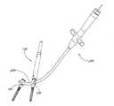
- FIG. 1is an overview of a system for minimally invasive posterior spinal fixation according to one embodiment of the present invention.
- FIG. 2is an exploded view of the bone anchor and the driver of FIG. 1 .
- FIG. 3Ais an enlarged view of the circled area in FIG. 2 .
- FIG. 3Billustrates an angularly adjustable connector with rotation limits according to another embodiment.
- FIG. 3Cillustrates a connector, a locking cap and its complementary inner adapter according to yet another embodiment.
- FIGS. 3D-3Fillustrate the connector illustrated in FIG. 3C in further detail.
- FIG. 3Gis a cross-sectional view of an angularly adjustable connector with rotation limits positioned within a head of a bone anchor according to another embodiment.
- FIG. 4is another view of the system for minimally invasive posterior spinal fixation illustrated in FIG. 1 , with the linkage rod detached from its insertion tool.
- FIG. 5is an enlarged view of the circled area in FIG. 4 .
- FIG. 6is another view of the system for minimally invasive posterior spinal fixation illustrated in FIG. 4 .
- FIGS. 7-12illustrate the use of positioning tools to position a guide wire into a vertebral body.
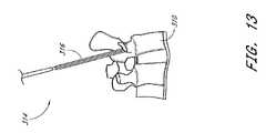
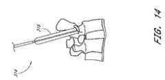
- FIGS. 13-14illustrate the use of a dilation balloon catheter to dilate a tissue tract.
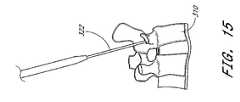
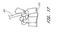
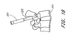
- FIGS. 15-20illustrate the positioning of a sheath adjacent to a vertebral body.
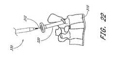
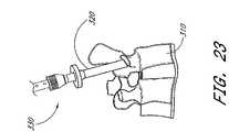
- FIGS. 21-23illustrate a drill used to create an opening in a vertebral body to receive a bone anchor.
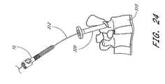
- FIGS. 24-25illustrate advancing a bone anchor over the wire towards a vertebral body.
- FIGS. 26-27illustrate a bone anchor and the driver used to insert the bone anchor into a vertebral body.
- FIGS. 28-31illustrate the use of the driver to insert a bone anchor into a vertebral body.
- FIG. 32illustrates two bone anchors positioned in two adjacent vertebral bodies.
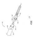
- FIG. 33illustrates an alignment device for positioning a guidewire though a bone anchor in accordance with one aspect of the present invention.
- FIG. 34illustrates a flexible obtuator for positioning within the arcuate arm of the alignment device.
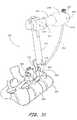
- FIG. 35illustrates a first alignment device coupled to first bone anchor, and a second alignment device coupled to a second bone anchor.
- FIGS. 36 and 37illustrate a guidewire capture device, for positioning within the arcuate arm on an alignment device.
- FIG. 38illustrates the first and second alignment devices, with a guidewire advancing from the first alignment device towards the capture device carried by the second alignment device.
- FIG. 39is an illustration as in FIG. 38 , after the guidewire has entered the guidewire capture device and traversed the curved arm on the second alignment device.
- FIG. 40is a side elevational view of a linkage rod, decoupled from an insertion tool, both over a guidewire.
- FIG. 41is a side elevational perspective view of a guidewire positioned through two adjacent bone anchors, and a linkage rod being advanced along the guidewire by an insertion tool.
- FIG. 42is an illustration as in FIG. 41 , with the linkage rod positioned within the first and second bone anchors.
- FIG. 43is an illustration as in FIG. 42 , with a driver in position to lock the first bone anchor to the linkage rod.
- FIG. 44is an illustration as in FIG. 43 , with a portion of the driver tool proximally retracted.
- FIG. 45is an illustration as in FIG. 44 , with the driver tool retracted, the first and second bone anchors locked onto the linkage rod, and the insertion tool decoupled from the linkage rod.
- FIG. 46is an illustration as in FIG. 45 , with the insertion tool and the guidewire removed from the linkage rod, illustrating a formed in place one level posterior fusion device in accordance with the present invention.
- FIG. 47is an illustration as in FIG. 46 , showing a two level fusion or fixation device, percutaneously assembled in accordance with the present invention.
- FIG. 48is a side elevational schematic view of an alternate linkage rod in accordance with the present invention.
- FIG. 49is an enlarged exploded view as in FIG. 3A , showing the proximal end of a bone anchor adapted for use with the linkage rod of FIG. 48 .
- One advantage of the prosthesis formation described in the various embodiments of the present inventionis the ability to access a treatment site through minimally invasive pathways, while allowing the formation of a relatively larger prosthesis at the treatment site.
- various components of a prosthesisare inserted into a patient through minimally invasive pathways, then joined to form a single prosthesis. This is facilitated by the angularly adjustable connectors between the various components, which provide leeway or angular adjustability as the components are joined. Afterwards, the junctions between the various components may be locked to fix or set the prosthesis in a desired configuration.
- a corollary advantage of several embodimentsis the ability to unlock and adjust one or more junctions between components of the prosthesis, to set the prosthesis in other desirable configurations during or even after its implantation and formation.
- the prosthesismay thus be adjusted in subsequent procedures.
- the systems and methods for spinal fixationminimize procedure morbidity by avoiding open surgical cutdowns or other invasive access procedures.
- the basic percutaneous access, bone screw construction and implantation methods, and methods and structures for percutaneously positioning a fixation rod across bone screws, all of which are useful in the practice of the present invention,are disclosed in U.S. patent application Ser. No. 09/747,066, entitled Percutaneous Vertebral Fusion System, to Teitelbaum, filed Dec. 21, 2000; U.S. patent application Ser. No. 09/943,636 to Shaolian et al., entitled Formable Orthopedic Fixation System, filed Aug. 29, 2001; U.S. patent application Ser. No.
- FIG. 1An overview of a system for minimally invasive posterior spinal fixation according to one embodiment of the present invention is provided in FIG. 1 .
- the systemincludes at least two and optionally three or four or more bone anchors 100 and a linkage rod 200 .
- the bone anchorsare shown connected by the linkage rod 200 .
- the systemalso includes a driver 150 , shown engaging one of the bone anchors 100 , and an insertion tool 250 , shown connected to the linkage rod 200 .
- the present inventionwill be described primarily in the context of a single linkage rod connected to two bone anchors, the normal fusion application will involve the implantation of two linkage rods, each carried by two or more bone anchors, bilaterally symmetrically mounted on the spine as is well understood in the art.
- FIG. 2shows an exploded view of the bone anchor 100 and the driver 150 .
- the bone anchor 100is provided with threads 102 by which it is screwed into a vertebral body.
- a connector 104 and a locking cap 106are disposed within the head 108 of the bone anchor 100 .
- the driver 150comprises an outer adapter 152 concentrically arranged around an inner adapter 154 .
- Either adaptermay be freely rotated with respect to the other.
- the outer adapter 152is adapted to engage the head 108 , to screw the bone anchor 100 into a bone.
- the inner adapter 154is adapted to engage the locking cap 106 , to tighten the connector 104 within the head 108 .
- the hexagonal proximal end 156 of the outer adapter 152allows torque to be applied to the outer adapter 152 by means of a wrench, a spanner or another tool.
- the hexagonal proximal end 158 of the inner adapter 154allows torque to be applied to the inner adapter 154 .
- Releasable, rotational engagement between the driver and the bone anchormay be accomplished in any of a variety of ways.
- the distal end the inner adapter 154is provided with at least one surface for cooperating with a complimentary surface on the proximal end of the bone anchor 100 , for transmitting torque from the inner adapter 154 to the bone anchor 100 , to enable transmission of torque from the inner adapter 154 to locking cap 106 .
- the distal end of the outer adapter 152is provided with at least one surface for cooperating with a complimentary surface on the proximal end of the bone anchor 100 , for transmitted torque from the outer adapter 152 to the bone anchor 100 to enable credible engagement between the bone anchor 100 and the vertebral body.
- the bone anchor 100 , its connector 104 , its locking cap 106 , and the inner adapter 154are all provided with a central axial lumen through which a guide wire 190 may pass.
- FIG. 3Ais an enlarged view of the circled area in FIG. 2 , showing the proximal head 108 of the bone anchor 100 and the distal ends of the outer adapter 152 and the inner adapter 154 .
- the connector 104 and the locking cap 106are disposed within the head 108 .
- the connector 104is spherical with an aperture 110 extending therethrough, and a gap 112 in its circumference, such that it is approximately C-shaped when viewed along the central axis of the aperture 110 .
- the aperture 110is adapted for the insertion of a linkage rod (not shown), and has a diameter slightly larger than that of the linkage rod.
- the connector 104can be provided in a variety of suitable shapes.
- the connector 104is seated on a race or groove 114 within the head 108 .
- the groove 114is preferably provided with a complementary surface to the spherical exterior surface of the connector 104 .
- the connector 104may rotate on any axis within the head 108 of the bone anchor (or bone screw) 100 .
- a locking cap 106may be threaded into the head 108 to lock the connector 104 against the linkage rod 200 , by compressing the groove 114 , fixing the connector 104 within the head 108 .
- the bottom of the locking cap 106may be provided with a concave surface (not shown) which is complementary to the spherical exterior surface of the connector 104 .
- a transverse portal 116extends through the head 108 along an axis approximately perpendicular to the central axis of the bone anchor 100 . While the aperture 110 of the connector 104 and the transverse portal 116 of the head 108 are illustrated as circular, they may be of different shapes in other embodiments, depending upon the cross sectional shape of the fixation rod (e.g. oval, elliptical, rectangular, square, etc.).
- the diameter of the transverse portal 116is generally smaller than the outside diameter of the uncompressed connector 104 but greater than the inside diameter of the aperture 110 .
- the connector 104Before the locking cap 106 is tightened, the connector 104 may rotate on any axis within the head 108 to accommodate different entrance angles for the fixation rod.
- the central axis of the aperture 110 and the central axis of the transverse portal 116may be coaxial or angularly offset.
- the threading of the locking cap 106 into the head 108compresses the connector 104 , decreasing the width of the gap 112 and reducing the cross sectional area of the aperture 110 .
- the tightening of the locking cap 106 into the head 108also fixes the rotational position of the connector 104 within the head 108 .
- FIG. 3Billustrates an alternate connector 104 ′. Similar to the connector 104 described above, the connector 104 ′ is provided with an aperture 110 ′ having a longitudinal axis and a gap 112 ′.
- the spherical exterior surface of the connector 104 ′is provided with one or two or three or more surface structures such as projections or indentations 111 .
- the indentations 111receive complementary surface structures such as projections provided within the head 108 of the bone anchor 100 to limit the degree of rotation of the connector 104 ′ within the head 108 .
- FIG. 3Gillustrates an exemplary embodiment wherein the complementary surface structure comprises a pin 101 that may be laser welded or otherwise coupled to or integrally formed with the screw head 108 .
- the pin 101interacts with the indentation 111 to limit the degree of rotation of the connector 104 ′ within the head 108 .
- the connector 104 ′is limited to about 30 degrees of rotation on any axis within the head 108 , from the longitudinal axis through the transverse portal 116 .
- the connector 104 ′may be limited to a range of up to about 60 degrees of rotation from the longitudinal axis.
- the connector 104 ′is limited to no more than about 5 degrees or about 10 degrees of rotation on any axis from the longitudinal axis.
- the rotation of the connector 104 ′is limited such that the aperture will always be exposed through transverse portal 116 to the linkage rod 200 .
- the linkage rod 200may be provided with a tapered distal end 201 .
- the tapered distal end 201may be machined or molded integrally with the linkage rod 200 , or may be separately formed and attached to the linkage rod 200 .
- the tapered end 201may be a polymeric component such as nylon, HDPE, PEBAX or other materials known in the art.
- the tapered tip 201facilitates advance of the linkage rod 200 through aperture 110 , by causing the connector 104 to pivot about its center of rotation into alignment for receiving the linkage rod 200 . In this manner, the connector 104 will self align with the linkage rod 200 to accommodate any of a wide variety of angular relationships that may be found in vivo.
- FIG. 3Cis similar to FIG. 3A above, and illustrates an inner adapter 154 ′ and a locking cap 106 ′ according to another embodiment.
- the inner adapter 154 ′is provided with a Torx distal end 158 ′ which is adapted to engage a complementary Torx opening 120 ′ at the top of the locking cap 106 ′.
- Any of a variety of complementary surface structuresmay be used, as will be understood in the art in view of the disclosure herein.
- FIG. 3Cillustrates a connector 104 ′′ according to another embodiment. Similar to the connectors 104 and 104 ′ described above, the connector 104 ′′ is provided with an aperture 110 ′′ and one or more compressible gaps 112 ′′. The gaps 112 ′′ are provided with a compressible material which compresses when the locking cap 106 ′ tightens the connector 104 ′′ against the groove 114 within the head 108 . Compressible material, including any of a variety of compressible polymeric materials known in the medical device arts can be used according to several embodiments of the present invention. One skilled in the art will appreciate that other suitable flexible or compressible materials may also be used.
- any of a variety of metal (stainless steel, titanium, etc.) connectors 104may be configured such that the aperture 110 is moveable from a first, large cross-section, for receiving a linkage rod 200 therethrough, to a second, reduced cross section for locking the linkage rod 200 in place. This may be accomplished by providing opposing components forming the side wall of the connector 104 with any of a variety of interlocking structures such as ramp and pawl ratchet structures, or sliding fit structures which permit a reduction in the diameter in the aperture 110 under compressive force from the locking cap 106 .
- interlocking structuressuch as ramp and pawl ratchet structures, or sliding fit structures which permit a reduction in the diameter in the aperture 110 under compressive force from the locking cap 106 .
- portions or all of the connector 104comprise a compressible media such as an open cell foam, closed cell foam or solid compressible material.
- a compressible mediasuch as an open cell foam, closed cell foam or solid compressible material.
- Structurescomprising polyethylene, PEEK, nylon, and other polymers known in the medical arts may be utilized, depending upon the construction and desired compressibility.
- the combination of material and the structure of the connector 104is sufficient to allow angular adjustment of the longitudinal axis of the aperture 110 , to accommodate various entrance angles of the linkage rod 200 .
- a locking elementsuch as locking cap 106 functions to both prevent axial movement of the linkage rod 200 within the aperture 110 , as well as prevent further angular adjustment of the longitudinal axis of the aperture 110 with respect to the longitudinal axis of the bone anchor 100 .
- FIGS. 3D-3Fillustrate the connector 104 ′′, the aperture 110 ′′, the gaps 112 ′′, and a compressible or foldable membrane or link 115 in greater detail.
- FIG. 3Dis an isometric view of the connector 104 ′′.
- FIG. 3Eis a front plan view of the connector 104 ′′ viewed along the central axis of the aperture 110 ′′.
- FIG. 3Fis the corresponding side plan view.
- the compressible linkis formed by grinding, laser etching, molding or otherwise forming a recess such as a V-shaped channel 113 that leaves a thin link 115 which folds flat when the connector 104 ′′ is compressed.
- compressible materials and structurescan be provided in a variety of suitable shapes and forms.
- the apertures 110 ′ and 110 ′′have a tendency to return to their original diameters even after the connectors 104 and 104 ′, respectively, are compressed by the locking cap 106 against the groove 114 within the head 108 .
- This tendencyresults from the resiliency of the metal, alloy or other material used to make the connectors 104 and 104 ′.
- the use of compressible material, such as V-shaped channels 113 in the gaps 112 ′′ of the connector 104 ′′reduces or eliminates this tendency and may allow a linkage rod (not shown) to be more firmly secured within the aperture 110 ′′.
- the connectors 104 and 104 ′can be made from lower resiliency materials which can also reduce or eliminate the tendency of apertures 110 ′ and 110 ′′ to return to their original diameters.
- the outer adapter 152is adapted to engage the head 108
- the inner adapter 154is adapted to engage the locking cap 106
- projections 156 on the distal end of the outer adapter 152are adapted to engage complementary projections 118 on the head 108 of the bone anchor 100
- the hexagonal distal end 158 of the inner adapter 154is adapted to engage a complementary hexagonal opening 120 at the top of the locking cap 106 .
- each of the inner adapter 154 and outer adapter 152is provided with a surface structure for enabling rotational engagement with a corresponding component on the implant.
- any of a variety of alternative structuresmay be utilized in which a first surface on the inner adapter 154 or outer adapter 152 cooperates with a second, complementary surface on the corresponding aspect of the bone anchor 100 , for allowing rotational engagement, followed by axial decoupling.
- the linkage rod 200is shown positioned within two adjacent bone anchors 100 , and released from the insertion tool 250 .
- the insertion tool 250is provided for the insertion of the linkage rod 200 into the bone anchors 100 .
- the insertion tool 250comprises an arm 252 and a handle 254 .
- the arm 252is curved to facilitate insertion of the linkage rod 200 into the bone anchors 100 within a patient along a curved tissue tract which passes through the aperture 110 of at least each of a first bone anchor and a second bone anchor.
- a central control line 256such as a torque transmission tube, rod or cable extends through an axial lumen of the insertion tool 250 , and terminates at a control such as a knob 258 at the proximal end of the insertion tool 250 .
- a screw(not shown) threaded into a tunnel 260 extending along a radius of the knob 258 may be used to secure the control line 256 within the knob 258 .
- the control line 256is provided with a threaded distal tip 262 . Rotating the knob 258 thus rotates the control line 256 and its threaded distal tip 262 to engage or disengage the linkage rod 200 .
- both the linkage rod 200 and the control line 256are provided with a central axial lumen for the passage over a guide wire.
- FIG. 5is an enlarged view of the circled area in FIG. 4 , showing the distal end of the outer adapter 152 , the bone anchor 100 , the linkage rod 200 , and the distal end of the arm 252 of the insertion tool.
- the linkage rod 200is shown fixed within the head 108 of the bone anchor 100 .
- the linkage rod 200is provided with a hexagonal proximal end 202 adapted to engage a complementary hexagonal socket (not shown) in the distal end of the arm 252 of the insertion tool.
- alternative complementary surface structuresmay be provided on the linkage rod 200 and the arm 252 to rotationally fix their orientation with respect to one another.
- the hexagonal proximal end 202is provided with a dimple 204 adapted to engage a complementary nub (not shown) within the hexagonal socket (not shown) in the distal end of the arm 252 of the insertion tool.
- the dimple 204 and nub (not shown)fix the axial orientation of the linkage rod 200 with respect to the arm 252 .
- the threaded distal tip 262 of the control line 256may be threaded into a complementary threaded hole 206 in the hexagonal proximal end 202 of the linkage rod 200 , enabling the linkage rod 200 to be detachably secured to the arm 252 of the insertion tool.
- the threaded distal tip 262may be threaded into the threaded hole 206 by rotating the knob (not shown) at the proximal end of the insertion tool. Unthreading the threaded distal tip 262 from the threaded hole 206 allows the linkage rod 200 to be released from the insertion tool 250 .
- the outer adapter 152is provided with an opening 160 extending along a diameter for fluoroscopic or other visualization of the rotational orientation of the outer adapter 152 , to align the portal 116 of the bone anchor 100 engaged by the outer adapter 152 .
- the axis of the opening 160is preferably arranged at a right angle to the axis of the portal 116 as shown in FIG. 5 .
- the inner adapter 154may be temporarily retracted so that it does not block the opening 160 .
- a translucent markermay be installed in opening 160 for fluoroscopic or other visualization of the outer adapter 152 .
- any of a variety of other indicium of the rotational orientation of the bone anchor 100may be provided.
- the complementary surface structures between the proximal end of the bone anchor 100 and the distal end of the insertion tool 250may be configured to only allow coupling between the two components in a predetermined rotational orientation.
- visual indiciamay be provided on a portion of the insertion tool 250 (e.g. “T” handle, painted or etched markings or other indicium) which remains external to the patient, to allow direct visual observation of the rotational orientation of the longitudinal axis of the transverse portal 116 .
- FIG. 6illustrates the described system from another angle.
- the knob and its attached central cablehave been removed for clarity.
- the hexagonal socket 264adapted to engage the hexagonal proximal end 202 of the linkage rod 200 , as described above, is shown.
- the nub 266adapted to engage the dimple (not shown) on the hexagonal proximal end 202 of the linkage rod 200 is also shown.
- the components of the bone anchor, the linkage rod, the driver, and the arm of the insertion toolmay be made of titanium, stainless steel or any other suitable metals, alloys, or material.
- the handle of the insertion toolis preferably made of a suitable non-slip material. The selection of these materials for the manufacture of the components and devices described in the above embodiments would be known by those skilled in the art.
- a trocar 300is inserted through a tissue tract and into a vertebral body 310 .
- the trocar 300comprises a sharp-tipped rod (not shown) attached to a proximal or top half-handle 302 .
- the sharp-tipped rodis arranged concentrically within a cannula 304 , which is attached to the bottom half-handle 306 of the trocar 300 .
- the top half-handle 302 and the bottom half-handle 306 of the trocar 300are screwed together for initial use, as shown in FIGS. 7-8 .
- the trocar 300is inserted through the skin, muscle and other tissues of the patient into the vertebral body 310 .
- the tip 308 of the sharp-tipped rodis visible in FIG. 16 .
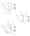
- FIG. 9shows the bottom half-handle 306 with the attached cannula 304 embedded in the vertebral body 310 .
- the top half-handle(not shown) has been unscrewed and set aside from the bottom half-handle 306 .
- a guide wire 312is inserted into the vertebral body 310 via the bottom half-handle 306 and the cannula 304 .
- the bottom half-handle 306 and the cannula 304are removed from the vertebral body 310 .
- the guide wire 312remains in place in the vertebral body 310 .
- FIG. 12shows the guide wire 312 in the vertebral body 310 after the bottom half-handle 306 and the cannula 304 are removed.
- FIGS. 13-14show one embodiment of the invention in which an inflatable tissue expander for enlarging the tissue tract is used.
- a balloon catheter 314 carrying a balloon 316is advanced over the guide wire 312 towards the vertebral body 310 .
- the balloon 316is inflated to dilate the tissues adjacent the access pathway to the vertebral body 310 . This provides an enlarged path for the insertion of a sheath as described below.
- a guide tube 322is advanced over the guide wire 312 into the vertebral body 310 .
- the guide tube 322may be approximately the same diameter as the cannula 304 of the trocar 300 , allowing the guide tube 322 to be inserted into the opening in the vertebral body 310 created earlier by the trocar 300 .
- the guide tube 322acts as a stable rail over which a tapered dilation cylinder 324 may be advanced against the vertebral body 310 .
- a tapered dilation cylinder 324is advanced over the guide tube 322 against the vertebral body 310 .
- the tapered dilation cylinder 324may be approximately the same diameter as the inflated dilation balloon 316 discussed above with reference to FIGS. 13-14 .
- the tapered dilation cylinder 324is used to occupy the path created by the dilation balloon, and facilitates the insertion of a sheath.
- the dilation cylinder 324is provided without a tapered distal end, and is distally advanced into position directly over the inflatable balloon.
- a sheath 320is advanced over the tapered dilation cylinder 324 against the vertebral body 310 .
- the sheath 320occupies the path created by the dilation balloon.
- the guide tube 322 and the tapered dilation cylinder 324are removed.
- the guide wire 312preferably remains in the vertebral body 310 after the placement of the sheath 320 .
- a drill 330 having a rotatable distal tip 332is advanced over the guide wire 312 and through the sheath 320 .
- the drill 330drills an opening (not shown) in the vertebral body 310 adapted for the insertion of a bone anchor 100 .
- the drill 330is removed.
- the bone anchor 100is advanced over the guide wire 312 and through the sheath 320 towards the vertebral body 310 .
- a bone anchor 100is advanced over the wire 312 and through the sheath 320 into engagement with the vertebral body 310 .
- the insertion tool 250is not illustrated, the bone anchor 100 may be coupled to the insertion tool 250 prior to the step of advancing the bone anchor 100 into contact with the vertebral body 310 .
- FIGS. 26 and 27show the outer adapter 152 and the inner adapter 154 of the driver 150 , as well as a bone anchor 100 , with the connector 104 and the locking cap 106 disposed within the head 108 of the bone anchor 100 .
- the interrelation of these componentshave been described in detail above with reference to FIGS. 2 and 3A .
- the outer adapter 152 illustrated in FIGS. 26-28additionally comprises a pivot hole 153 which extend through a diameter of the outer adapter 152 .
- the pivot hole 153is adapted for the attachment of a guide wire insertion device 400 described in further detail below.
- these componentsare shown arranged over a guide wire 190 .
- the driver 150(comprising the outer adapter 152 and the inner adapter 154 ) is advanced over the guide wire 312 until the driver 150 engages the bone anchor 100 .
- torqueis applied to the outer adapter 152 to screw the bone anchor 100 into the vertebral body 310 .
- the driver 150is removed, leaving the bone anchor 100 in place, with the longitudinal axis of the portal 116 aligned approximately parallel with the longitudinal axis of the spine.
- the sheath 320discussed above with reference to FIGS. 18-25 , while not shown in the steps discussed with reference to FIGS. 28-31 , may nonetheless be used to shield the driver from adjacent tissue in these steps, as will be understood by those skilled in the art.
- a second bone anchor 340has been inserted into another vertebral body 350 . While bone anchors 100 and 340 are shown inserted into adjacent vertebral bodies 310 and 350 , respectively, the system and methods for minimally invasive spinal fixation according to the embodiments of the present invention are also applicable to nonadjacent vertebral bodies.
- a first bone anchormay be positioned in a first vertebral body as has been described above.
- a second bone anchormay be positioned in a second vertebral body, spaced apart from the first vertebral body by one or more intervening third vertebral bodies.
- the first and second bone anchorsmay thereafter be connected by the implantation of a linkage rod 200 .
- a third bone anchormay be positioned in a third vertebral body, positioned in between the first and second vertebral bodies to produce, for example, a three level fusion system as will be discussed.
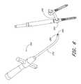
- FIG. 33shows an overview of the guide wire insertion device 400 according to one embodiment of the invention.
- the guide wire insertion devicecomprises a handle 410 and a hollow access needle 450 .
- the handle 410is detachably joined to the outer adapter 152 of the driver 150 .
- the handle 410is forked at its proximal end 412 .
- Each forkis provided with a pivot pin 414 , which engages the pivot hole 153 ( FIG. 28 ) of the outer adapter 152 .
- the forked proximal end 412 of the handle 410may be spread slightly to allow the pivot pins 414 to engage the pivot hole 153 .
- the handle 410swings on its pivot pins 414 at the pivot hole 153 of the outer adapter 152 of the driver 150 to insert the access needle 450 through the transverse portal 116 of the bone anchor 100 .
- a hollow access needle 450is attached to the distal end 416 of the handle 410 .
- the access needle 450is disposed within an opening 418 at the distal end 416 of the handle 410 .
- a screw(not shown) may be threaded through a screw hole 420 at the distal end 416 of the handle 410 to tighten the access needle 450 within the opening 418 .
- the lengthwise position of the access needle 450 within the opening 418is therefore adjustable to allow the access needle 450 to be aimed through the transverse portal 116 of the bone anchor 100 .
- the access needle 450may be aimed such that it passes through the transverse portal 116 at a point lower (towards the threads 102 in FIG. 2 ) than the center of the transverse portal 116 because obstructions encountered during the in vivo insertion of the access needle 450 may deflect the needle 450 towards the inside of its curvature and the center of the transverse portal 116 .
- the sharp, tapered distal end 452 of the access needle 450terminates at an opening 454 .
- the access needle 450is provided with threaded proximal end 456 , the purpose of which is described in further detail below.
- FIG. 34illustrates a flexible obturator 500 of the guide wire insertion device 400 according to one embodiment.
- the obturator 500comprises a tubing 502 , a threaded cap 504 on its proximal end and a plug 506 on its distal end.
- the tubing 502is sized such that it fits snugly within the hollow access needle 450 and occupies the length of its lumen.
- the cap 504can be made with a threaded luer connector which may be tightened onto the threaded proximal end 456 of the access needle 450 .
- the plug 506may be formed from an adhesive, for example, Loctite 3104 , etc.
- the obturator 500occupies the lumen of the access needle 450 , and minimizes the collection of tissue or other matter within the access needle 450 as it is advanced through the patient.
- FIG. 35shows a first guide wire insertion device 400 joined to a first outer adapter 152 engaging a first bone anchor 100 and a second guide wire insertion device 400 ′ joined to the outer adapter 152 ′ engaging a second bone anchor 340 .
- both handles 410 and 410 ′are pivoted with respect to outer adapters 152 and 152 ′ to advance access needles 450 and 450 ′ through the patient's tissues and towards the transverse portals 116 of bone anchors 100 and 340 , respectively.
- FIG. 35also shows an obturator 500 according to one embodiment being inserted into the access needle 450 of the guide wire insertion device 400 as described above with reference to FIG. 34 .
- the obturator 500is inserted into the access needle 450 and threaded onto its threaded proximal end 456 before the access needle 450 is inserted into the patient.
- another obturator 500may be inserted into the access needle 450 ′.
- the guide wire insertion device 400additionally comprises a guide wire snare or capture device 530 , illustrated in FIG. 36 .
- the guide wire capture device 530comprises an inner tubing 532 located coaxially within an outer tubing 534 .
- the inner tubing 532is provided with an inner half-cone 536 and the outer tubing 534 is provided with an outer half cone 538 .
- the inner half-cone 536may be furled and retracted within the outer tubing 534 .
- the outer half-cone 536may be furled to ease its insertion into and navigation through the lumen of the hollow access needle 450 .
- Inner half-cone 536may be rotationally oriented with respect to outer half-cone 538 to form the conical funnel 540 of the guide wire capture device 530 , as illustrated in FIG. 37 .
- the guide wireis directed into the lumen 542 of the inner tubing 532 .
- the guide wire capture device 530also additionally comprises a handle 544 in the illustrated embodiment.
- the access needle 450has been advanced through the transverse portal 116 of bone anchor 100
- access needle 450 ′has been advanced through the transverse portal 116 of bone anchor 340
- the guide wire capture device 530is inserted through the lumen of the access needle 450 , and its conical funnel 540 is deployed.
- a guide wire 368is inserted through the lumen of the access needle 450 ′ and advanced towards the conical funnel 540 of the guide wire capture device 530 .
- the guide wire 368contacts the conical funnel 540 , the guide wire 368 is directed into the lumen 542 of the inner tubing 532 of the guide wire capture device 530 .
- the guide wire 368is advanced through the lumen 542 of the inner tubing 532 until it extends past the handle 544 of the guide wire capture device 530 .
- Various methods of inserting guide wiresare known in the art and the invention is not limited to the methods disclosed herein. Instead, any method of inserting a guide wire known to those skilled in the art may be used in accordance with the present invention.
- the first insertion device 400 and second insertion device 400 ′may be removed.
- a flexible or curved bone drillmay be advanced along the guide wire 368 to clear a path between the transverse portals 116 of bone anchors 100 and 340 .
- the bone drill arm carrying the drill bitis provided with a certain degree of flexibility to allow it to travel along the arcuate course of the guide wire 368 .
- the curvature the bone drill arm carrying the drill bitis matched to the curvature of the linkage rod 200 to ensure that the path cleared between transverse portals 116 of bone anchors 100 and 340 fits the linkage rod 200 .
- the bone drillis removed from the guide wire 368 after a path has been cleared between transverse portals 116 of bone anchors 100 and 340 .
- a linkage rod 200 and its insertion tool 250are shown arranged over the guide wire 368 .
- the linkage rod 200 and insertion tool 250are described above with reference to FIGS. 4-6 .
- the linkage rod 200 and insertion tool 250 in the embodiment illustrated in FIG. 40are provided with slightly different indexing features than the linkage rod and insertion tool described with reference to FIGS. 4-6 .
- the linkage rod 200is provided with one or more bumps 220 on its hexagonal proximal end 202 .
- the bumps 220are complementary with one or more holes 280 at the distal end of the insertion tool 250 .
- the linkage rod 200is detached from the insertion tool 250 .
- the attachment of the linkage rod 200 to the insertion tool 250is described above with reference to FIGS. 4-6 .
- the insertion tool 250is used to advance the linkage rod 200 over the guide wire 368 towards the bone anchors 100 and 340 . While the linkage rod 200 is inserted from a rostral or sacral approach (tail-to-head) in the illustrated embodiment, it may also be inserted from a caudal approach (head-to-tail) in another embodiment.
- the linkage rod 200is inserted through the respective connectors 104 within bone anchors 100 and 340 .
- the connector 104 within the bone anchor 100is described above with reference to FIGS. 2-3 .
- the inner adapter 154 of the driver 150is used to tighten the locking cap 106 within the bone anchor 340 , fixing the linkage rod 200 within the bone anchor 340 , as described above with reference to FIGS. 2-3 .
- the outer adapter 152 of the driver 150engages the head of bone anchor 340 to prevent it from rotating as the locking cap is tightened.
- the engagement between the bone anchor 340 and the driver 150is described above with reference to FIGS. 1-3 in the context of bone anchor 100 .
- the driver 150(comprising the outer adapter 152 and the inner adapter 154 ) is withdrawn from the bone anchor 340 .
- the locking cap 106 in the bone anchor 100is similarly tightened, fixing the linkage rod 200 within the bone anchor 100 .
- the insertion tool 250is released from the linkage rod 200 .
- the attachment and detachment of the linkage rod 200 to and from the insertion tool 250is discussed above with reference to FIGS. 4-6 .
- the driver 150 , the sheath 320 and the guide wire 368are removed from the patient.
- FIG. 46illustrates the percutaneously assembled in place prosthesis resulting from the procedure described above, comprising the bone anchors 100 , 340 and the linkage rod 200 .
- FIG. 47illustrates a three level prosthesis comprising an additional bone anchor inserted into an additional adjacent vertebral body, to provide a three level spinal fusion.
- FIG. 48illustrates a side elevational view of a modified linkage rod 200 .
- Linkage rod 200 in FIG. 48may be the same general dimensions and configuration as the linkage rods disclosed previously herein, except as described below.
- the linkage rod 200comprises an elongate body 401 extending between a proximal end 402 and a distal end 404 .
- the length of the body 401 in a device intended for use in a human adult one level lumbar or lumbar-sacral fusionwill generally be in the range from about 30 mm to about 90 mm.
- a linkage rod 200 intended for a two level fusion in the same environmentwill generally have a length within the range of from about 50 mm to about 110 mm.
- the diameter of the body 401will generally be in the range of from about 3 mm to about 8 mm. In one embodiment, the diameter of the body 401 in a two level fusion device is about 6.35 mm. In general, the cross sectional area of the body 401 , which may be expressed as a diameter in a circular cross sectional implementation, may be varied depending upon the desired structural integrity of the finished implant.
- the distal end 404 of the body 401may be provided with a distal opening 408 to a central guidewire lumen, not illustrated.
- the distal end 404may also be provided with tapered tip 406 as has been previously discussed.
- the tapered tip 406may facilitate navigation through the tissue tract, as well as introduction of the body 401 into the bone anchor.
- Tapered tip 406may be integrally formed with the body 401 , or attached thereto in a subsequent manufacturing step.
- the body 401is generally provided with a preformed curve, such that it forms a portion of an arc as illustrated.
- the archas an approximately constant radius of curvature along the length the body 401 .
- the radius of curvature of body 401is generally in excess of about 19 cm, and, in many embodiments, within the range of from about 8 cm to about 30 cm.
- the overall length of the body 401is about 65 mm, the diameter is about 6.35 mm, and the radius of curvature is about 19 cm.
- the radius of curvature of the body 401may be equal or approximately the same as the radius of curvature of the hollow access needle 450 in the guidewire insertion device 400 discussed previously.
- the radiusmay be approximately equal to the distance between the access needle 450 and the pivot point 414 , which is also equal to the effective lever arm length of the handle 410 . This facilitates introduction of the linkage rod 200 along the same curved tissue tract used by or created by the access needle 450 .
- the linkage rod 200 illustrated in FIG. 48unlike the embodiments previously illustrated herein, includes a distinct distal locking surface 410 formed by a discontinuity in the outer profile of the body 401 .
- the distal locking surface 410is in the form of an increase in the cross sectional area of the body 401 , such as a spherical or curved enlargement of the profile of the body 401 .
- This distal locking surface 410is adapted to cooperate with a modified bone anchor, illustrated in FIG. 49 .
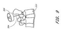
- FIG. 49is an enlarged, explored view of the proximal end of the bone anchor and distal end of a driver tool as illustrated in FIG. 3A , except that the connector 104 has been omitted from the embodiment illustrated in FIG. 49 .
- the distal locking surface 410is adapted for insertion through the transverse portal 116 and positioning within the proximal head 108 .
- the locking cap 106may be threadably distally advanced into the head 108 , to compress against the distal locking surface 410 and lock the bone anchor with respect to the linkage rod throughout any of a variety of angular orientations, as had been discussed previously.
- the distal wall of the chamber within the head 108may be provided with a complimentary curved surface for cooperating with the distal locking surface 410 .
- the distal surface on the locking cap 106may be concave in the distal direction, to increase the surface area of contact between the locking cap 106 and the distal locking surface 410 .
- Proximal locking surface 412is carried by an axially moveable tubular collar 414 .
- the collar 414comprises a generally tubular body axially movably carried by the body 401 of the linkage rod 200 .
- the proximal locking surface 412comprises a spherical, semi-spherical, curved or other enlargement in the cross-sectional area collar 414 , to provide a locking surface which may be useful throughout a variety of angular orientations as has described.
- One or two or three or four more axially extending slots 416may be provided on the proximal lock, to facilitate compression of the lock from a slideable orientation to a locked orientation in which it is compressed against the body 401 .
- two or more axially extending slotsextend in a proximal direction from the distal end of the lock.
- the linkage rod 200is advanced distally along a guidewire, through a tube, or otherwise through the first and second bone anchors.
- the locking cap 106 of the distal bone anchoris tightened to lock the linkage rod 200 with respect the distal bone anchor.
- the proximal lockis thereafter axially distally advanced along the insertion tool and/or linkage rod 200 , until the proximal locking surface 412 is positioned within the head 108 of the proximal bone anchor.
- the locking cap 106 of the proximal bone anchoris tightened, to lock the proximal locking surface 412 against the body 401 .
- the proximal lockmay be distally advanced along the insertion tool and/or linkage rod 200 in any of a variety of manners, such as by distally advancing a pusher sleeve which is axially movably carried on the insertion tool.
- the transverse portal 116 of the proximal bone anchoris provided with a proximal opening having a first diameter and distal opening having a second, smaller diameter.
- the outside diameter of proximal locking surface 412is dimensioned relative to the portal 116 such that it can pass through the proximal opening on the transverse portal 116 but cannot pass distally through the distal opening of the transverse portal 116 . In this manner, the clinician can perceive tactile feedback once the proximal lock has been distally advanced into position within the head 108 .
- This same constructioncan be utilized on the distal bone anchor as well, such that distal advancement of the distal locking surface 410 may be accomplished until the positive stop is felt by the clinician as the distal locking surface 410 is seated within the head 108 .
- the driver toolcan be provided with indicium of the rotational position of the bone anchor.
- the insertion toolmay be provided with a curved distal region, having a radius of curvature which approximates the radius of curvature of the linkage rod, described above.
- both the linkage rod 200 and the distal portion of the insertion toolare provided with a curve having a radius of approximately 12 cm. This further facilitates introduction of the linkage rod and insertion tool along a curved tissue tract, while minimizing trauma to surrounding tissue, as the linkage rod 200 is navigated through the first and second bone anchors.
- the foregoing constructionalso allows the percutaneous access site for the introduction of the linkage rod 200 to be predetermined distance from the longitudinal axis of the driver 150 .
- the radius of curvature of the curved needle 450is approximately 9 cm. This enables the percutaneous access site to be approximately 8 centimeters from the percutaneous entry site for the driver 150 .
- the transdermal access site for the linkage rodis preferably no more than about one radius away from the driver 150 . This allows minimization of the length of the tissue tract, and thus minimizes the access induced trauma to surrounding tissue.
- the guidewiremay be positioned through portals of adjacent bone anchors utilizing either the procedures disclosed in the copending patent applications previously incorporated by reference herein.
- the guidewiremay be positioned utilizing the pivotable guidance system disclosed herein.
- a tubular sleevemay be advanced over the guidewire and through the portals on bone anchors 100 , with the guidewire thereafter removed.
- the linkage rod 200may thereafter be advanced through the tubular sleeve.
- the linkage rod 200may be advanced utilizing the manual insertion tool 250 , as disclosed herein.
- the linkage rod 200may be releasably connected to the distal end of a curved pivotable arm 450 , using releasable connection structures disclosed elsewhere herein.
- the pivotable insertion systemsuch as that illustrated in FIG. 33 can be utilized to insert the linkage rod 200 through one or more apertures 116 in one or more bone anchors 100 .
Landscapes
- Health & Medical Sciences (AREA)
- Orthopedic Medicine & Surgery (AREA)
- Life Sciences & Earth Sciences (AREA)
- Neurology (AREA)
- Surgery (AREA)
- Engineering & Computer Science (AREA)
- Biomedical Technology (AREA)
- General Health & Medical Sciences (AREA)
- Veterinary Medicine (AREA)
- Heart & Thoracic Surgery (AREA)
- Public Health (AREA)
- Animal Behavior & Ethology (AREA)
- Nuclear Medicine, Radiotherapy & Molecular Imaging (AREA)
- Medical Informatics (AREA)
- Molecular Biology (AREA)
- Oral & Maxillofacial Surgery (AREA)
- Dentistry (AREA)
- Vascular Medicine (AREA)
- Transplantation (AREA)
- Cardiology (AREA)
- Surgical Instruments (AREA)
- Prostheses (AREA)
Abstract
Description
Claims (21)
Priority Applications (21)
| Application Number | Priority Date | Filing Date | Title |
|---|---|---|---|
| US10/462,098US7473267B2 (en) | 2003-04-25 | 2003-06-13 | System and method for minimally invasive posterior fixation |
| US10/642,399US7083621B2 (en) | 2003-04-25 | 2003-08-15 | Articulating spinal fixation rod and system |
| CNB2004800145448ACN100418485C (en) | 2003-04-25 | 2004-04-09 | Systems and methods for minimally invasive posterior fixation |
| AT04760245TATE536823T1 (en) | 2003-04-25 | 2004-04-09 | SYSTEM FOR MINIMALLY INVASIVE POSTERIOR FIXATION |
| KR1020057020324AKR101056313B1 (en) | 2003-04-25 | 2004-04-09 | Minimally invasive rear fixation device and method |
| PCT/US2004/010902WO2004096080A2 (en) | 2003-04-25 | 2004-04-09 | System and method for minimally invasive posterior fixation |
| CA002525491ACA2525491A1 (en) | 2003-04-25 | 2004-04-09 | System and method for minimally invasive posterior fixation |
| EP04760245AEP1622525B1 (en) | 2003-04-25 | 2004-04-09 | System for minimally invasive posterior fixation |
| AT09164057TATE538733T1 (en) | 2003-04-25 | 2004-04-09 | SYSTEM FOR MINIMALLY INVASIVE POSTERIOR SPINE FIXATION |
| JP2006509829AJP4481301B2 (en) | 2003-04-25 | 2004-04-09 | Guide wire insertion device |
| AU2004233794AAU2004233794A1 (en) | 2003-04-25 | 2004-04-09 | System and method for minimally invasive posterior fixation |
| EP09164057AEP2098178B1 (en) | 2003-04-25 | 2004-04-09 | System for minimally invasive posterior spinal fixation |
| EP04780882AEP1663028A4 (en) | 2003-04-25 | 2004-08-12 | Articulating spinal fixation rod and system |
| JP2006523927AJP2007502662A (en) | 2003-04-25 | 2004-08-12 | Fixed rod |
| CNB200480027587XACN100553573C (en) | 2003-04-25 | 2004-08-12 | Articulate spinal fixation bar and system |
| PCT/US2004/026112WO2005018490A2 (en) | 2003-04-25 | 2004-08-12 | Articulating spinal fixation rod and system |
| CA002535797ACA2535797A1 (en) | 2003-04-25 | 2004-08-12 | Articulating spinal fixation rod and system |
| AU2004266653AAU2004266653B2 (en) | 2003-04-25 | 2004-08-12 | Articulating spinal fixation rod and system |
| US11/428,269US8211153B2 (en) | 2003-04-25 | 2006-06-30 | Articulating spinal fixation rod and system |
| US12/328,914US8317838B2 (en) | 2003-04-25 | 2008-12-05 | System and method for minimally invasive posterior fixation |
| US13/650,390US20130035726A1 (en) | 2003-04-25 | 2012-10-12 | System and method for minimally invasive posterior fixation |
Applications Claiming Priority (3)
| Application Number | Priority Date | Filing Date | Title |
|---|---|---|---|
| US46590203P | 2003-04-25 | 2003-04-25 | |
| US10/462,098US7473267B2 (en) | 2003-04-25 | 2003-06-13 | System and method for minimally invasive posterior fixation |
| US10/642,399US7083621B2 (en) | 2003-04-25 | 2003-08-15 | Articulating spinal fixation rod and system |
Related Child Applications (1)
| Application Number | Title | Priority Date | Filing Date |
|---|---|---|---|
| US12/328,914DivisionUS8317838B2 (en) | 2003-04-25 | 2008-12-05 | System and method for minimally invasive posterior fixation |
Publications (2)
| Publication Number | Publication Date |
|---|---|
| US20040215190A1 US20040215190A1 (en) | 2004-10-28 |
| US7473267B2true US7473267B2 (en) | 2009-01-06 |
Family
ID=42561184
Family Applications (5)
| Application Number | Title | Priority Date | Filing Date |
|---|---|---|---|
| US10/462,098Expired - LifetimeUS7473267B2 (en) | 2003-04-25 | 2003-06-13 | System and method for minimally invasive posterior fixation |
| US10/642,399Expired - Fee RelatedUS7083621B2 (en) | 2003-04-25 | 2003-08-15 | Articulating spinal fixation rod and system |
| US11/428,269Expired - Fee RelatedUS8211153B2 (en) | 2003-04-25 | 2006-06-30 | Articulating spinal fixation rod and system |
| US12/328,914Expired - LifetimeUS8317838B2 (en) | 2003-04-25 | 2008-12-05 | System and method for minimally invasive posterior fixation |
| US13/650,390AbandonedUS20130035726A1 (en) | 2003-04-25 | 2012-10-12 | System and method for minimally invasive posterior fixation |
Family Applications After (4)
| Application Number | Title | Priority Date | Filing Date |
|---|---|---|---|
| US10/642,399Expired - Fee RelatedUS7083621B2 (en) | 2003-04-25 | 2003-08-15 | Articulating spinal fixation rod and system |
| US11/428,269Expired - Fee RelatedUS8211153B2 (en) | 2003-04-25 | 2006-06-30 | Articulating spinal fixation rod and system |
| US12/328,914Expired - LifetimeUS8317838B2 (en) | 2003-04-25 | 2008-12-05 | System and method for minimally invasive posterior fixation |
| US13/650,390AbandonedUS20130035726A1 (en) | 2003-04-25 | 2012-10-12 | System and method for minimally invasive posterior fixation |
Country Status (8)
| Country | Link |
|---|---|
| US (5) | US7473267B2 (en) |
| EP (3) | EP2098178B1 (en) |
| JP (2) | JP4481301B2 (en) |
| KR (1) | KR101056313B1 (en) |
| CN (2) | CN100418485C (en) |
| AU (2) | AU2004233794A1 (en) |
| CA (2) | CA2525491A1 (en) |
| WO (2) | WO2004096080A2 (en) |
Cited By (59)
| Publication number | Priority date | Publication date | Assignee | Title |
|---|---|---|---|---|
| US20050021031A1 (en)* | 1999-10-20 | 2005-01-27 | Foley Kevin T. | Instruments and methods for stabilization of bony structures |
| US20060276803A1 (en)* | 2005-05-24 | 2006-12-07 | Anthony Salerni | Electromagnetically guided spinal rod system and related methods |
| US20070179501A1 (en)* | 2006-01-13 | 2007-08-02 | Paul Firkins | Spinal Rod Support Kit |
| US20090048632A1 (en)* | 2005-10-22 | 2009-02-19 | Paul Firkins | Spinal Support Rod Kit |
| US20090198280A1 (en)* | 2007-10-24 | 2009-08-06 | Frank Spratt | Assembly for Orthopaedic Surgery |
| US20090222042A1 (en)* | 2005-10-22 | 2009-09-03 | Paul Firkins | Implant Kit For Supporting A Spinal Column |
| US20100049252A1 (en)* | 2008-08-21 | 2010-02-25 | Southern Spine, Llc | Transverse Connector Device for Extending an Existing Spinal Fixation System |
| US20100049199A1 (en)* | 2008-02-21 | 2010-02-25 | Tyco Healthcare Group Lp | Tibial guide for acl repair having moveable distal features |
| US20100049198A1 (en)* | 2008-02-21 | 2010-02-25 | Tyco Healthcare Group Lp | Tibial guide for acl repair having off-axis guide wire arrangement |
| US20100049196A1 (en)* | 2008-02-21 | 2010-02-25 | Tyco Healthcare Group Lp | Tibial guide for acl repair having interchangeable and/or rotatable outrigger |
| US20100049197A1 (en)* | 2008-02-21 | 2010-02-25 | Tyco Healthcare Group Lp | Tibial guide for acl repair having left/right docking configuration |
| US20100063548A1 (en)* | 2008-07-07 | 2010-03-11 | Depuy International Ltd | Spinal Correction Method Using Shape Memory Spinal Rod |
| DE202010005202U1 (en) | 2010-04-14 | 2010-06-17 | Aesculap Ag | Orthopedic fixation system and target device for such a fixation system |
| US20100292742A1 (en)* | 2009-05-13 | 2010-11-18 | Stad Shawn D | Torque Limited Instrument For Manipulating A Spinal Rod Relative to a Bone Anchor |
| US20110093074A1 (en)* | 2009-10-15 | 2011-04-21 | Chad Glerum | Expandable Fusion Device and Method of Installation Thereof |
| US20110093014A1 (en)* | 2009-10-19 | 2011-04-21 | Zimmer Spine, Inc. | Rod with Removable End and Inserter Therefor |
| DE102010016448A1 (en) | 2010-04-14 | 2011-10-20 | Aesculap Ag | Orthopedic fixation system and target device for such a fixation system |
| US8142437B2 (en) | 2010-06-18 | 2012-03-27 | Spine Wave, Inc. | System for percutaneously fixing a connecting rod to a spine |
| US8348952B2 (en) | 2006-01-26 | 2013-01-08 | Depuy International Ltd. | System and method for cooling a spinal correction device comprising a shape memory material for corrective spinal surgery |
| US8394108B2 (en) | 2010-06-18 | 2013-03-12 | Spine Wave, Inc. | Screw driver for a multiaxial bone screw |
| US8454664B2 (en) | 2010-06-18 | 2013-06-04 | Spine Wave, Inc. | Method for fixing a connecting rod to a thoracic spine |
| US8512383B2 (en) | 2010-06-18 | 2013-08-20 | Spine Wave, Inc. | Method of percutaneously fixing a connecting rod to a spine |
| US8777954B2 (en) | 2010-06-18 | 2014-07-15 | Spine Wave, Inc. | Pedicle screw extension for use in percutaneous spinal fixation |
| US8828058B2 (en) | 2008-11-11 | 2014-09-09 | Kspine, Inc. | Growth directed vertebral fixation system with distractible connector(s) and apical control |
| US8920472B2 (en) | 2011-11-16 | 2014-12-30 | Kspine, Inc. | Spinal correction and secondary stabilization |
| US9011491B2 (en) | 2004-08-03 | 2015-04-21 | K Spine, Inc. | Facet device and method |
| US9066814B2 (en) | 2010-08-02 | 2015-06-30 | Ulrich Medical Usa, Inc. | Implant assembly having an angled head |
| US9168071B2 (en) | 2009-09-15 | 2015-10-27 | K2M, Inc. | Growth modulation system |
| US9173681B2 (en) | 2009-03-26 | 2015-11-03 | K2M, Inc. | Alignment system with longitudinal support features |
| US9295500B2 (en) | 2013-06-12 | 2016-03-29 | Spine Wave, Inc. | Screw driver with release for a multiaxial bone screw |
| US9333009B2 (en) | 2011-06-03 | 2016-05-10 | K2M, Inc. | Spinal correction system actuators |
| US9452000B2 (en) | 2013-10-07 | 2016-09-27 | K2M, Inc. | Rod reducer |
| US9451987B2 (en) | 2011-11-16 | 2016-09-27 | K2M, Inc. | System and method for spinal correction |
| US9468471B2 (en) | 2013-09-17 | 2016-10-18 | K2M, Inc. | Transverse coupler adjuster spinal correction systems and methods |
| US9468469B2 (en) | 2011-11-16 | 2016-10-18 | K2M, Inc. | Transverse coupler adjuster spinal correction systems and methods |
| US9468468B2 (en) | 2011-11-16 | 2016-10-18 | K2M, Inc. | Transverse connector for spinal stabilization system |
| US9713488B2 (en) | 2008-02-04 | 2017-07-25 | Medos International Sarl | Methods for correction of spinal deformities |
| US9724130B2 (en) | 2013-03-14 | 2017-08-08 | Medos International Sarl | Locking compression members for use with bone anchor assemblies and methods |
| US9724145B2 (en) | 2013-03-14 | 2017-08-08 | Medos International Sarl | Bone anchor assemblies with multiple component bottom loading bone anchors |
| US9750546B2 (en) | 2014-08-11 | 2017-09-05 | Spinal Elements, Inc. | Articulating rod inserter |
| US9775660B2 (en) | 2013-03-14 | 2017-10-03 | DePuy Synthes Products, Inc. | Bottom-loading bone anchor assemblies and methods |
| US9782204B2 (en) | 2012-09-28 | 2017-10-10 | Medos International Sarl | Bone anchor assemblies |
| US9918747B2 (en) | 2013-03-14 | 2018-03-20 | DePuy Synthes Products, Inc. | Bone anchor assemblies and methods with improved locking |
| US9943344B2 (en) | 2015-01-15 | 2018-04-17 | K2M, Inc. | Rod reducer |
| US10045803B2 (en) | 2014-07-03 | 2018-08-14 | Mayo Foundation For Medical Education And Research | Sacroiliac joint fusion screw and method |
| US10052140B2 (en) | 2016-10-05 | 2018-08-21 | Stryker European Holdings I, Llc | Apparatus and method for fenestrated screw augmentation |
| US10085778B2 (en) | 2016-03-04 | 2018-10-02 | Spinal Elements, Inc. | Rod reducer instrument for spinal surgery |
| WO2019118844A1 (en)* | 2017-12-14 | 2019-06-20 | K2M, Inc. | Band tensioning system |
| US10342582B2 (en) | 2013-03-14 | 2019-07-09 | DePuy Synthes Products, Inc. | Bone anchor assemblies and methods with improved locking |
| US10405896B2 (en) | 2015-04-30 | 2019-09-10 | K2M, Inc. | Rod reducer |
| US10413332B2 (en) | 2016-04-25 | 2019-09-17 | Imds Llc | Joint fusion implant and methods |
| US10485590B2 (en) | 2017-01-18 | 2019-11-26 | K2M, Inc. | Rod reducing device |
| US10524843B2 (en) | 2016-05-06 | 2020-01-07 | K2M, Inc. | Rotation shaft for a rod reducer |
| US10603177B2 (en) | 2016-04-25 | 2020-03-31 | Imds Llc | Joint fusion instrumentation and methods |
| US10702311B2 (en) | 2011-11-16 | 2020-07-07 | K2M, Inc. | Spinal correction and secondary stabilization |
| US10779866B2 (en) | 2016-12-29 | 2020-09-22 | K2M, Inc. | Rod reducer assembly |
| US11864801B2 (en) | 2019-07-31 | 2024-01-09 | Seaspine, Inc. | Implantable universal connector |
| US12127766B2 (en) | 2021-03-05 | 2024-10-29 | Medos International Sàrl | Selectively locking polyaxial screw |
| US12324610B2 (en) | 2021-04-28 | 2025-06-10 | Spinal Elements, Inc. | Lever reducer |
Families Citing this family (531)
| Publication number | Priority date | Publication date | Assignee | Title |
|---|---|---|---|---|
| US20060241602A1 (en)* | 2000-06-06 | 2006-10-26 | Jackson Roger P | Hooked transverse connector for spinal implant system |
| US7833250B2 (en) | 2004-11-10 | 2010-11-16 | Jackson Roger P | Polyaxial bone screw with helically wound capture connection |
| GB0108228D0 (en) | 2001-04-02 | 2001-05-23 | Glaxo Group Ltd | Medicament dispenser |
| US8292926B2 (en) | 2005-09-30 | 2012-10-23 | Jackson Roger P | Dynamic stabilization connecting member with elastic core and outer sleeve |
| US10729469B2 (en) | 2006-01-09 | 2020-08-04 | Roger P. Jackson | Flexible spinal stabilization assembly with spacer having off-axis core member |
| US7862587B2 (en) | 2004-02-27 | 2011-01-04 | Jackson Roger P | Dynamic stabilization assemblies, tool set and method |
| US8353932B2 (en) | 2005-09-30 | 2013-01-15 | Jackson Roger P | Polyaxial bone anchor assembly with one-piece closure, pressure insert and plastic elongate member |
| US10258382B2 (en) | 2007-01-18 | 2019-04-16 | Roger P. Jackson | Rod-cord dynamic connection assemblies with slidable bone anchor attachment members along the cord |
| US20160242816A9 (en)* | 2001-05-09 | 2016-08-25 | Roger P. Jackson | Dynamic spinal stabilization assembly with elastic bumpers and locking limited travel closure mechanisms |
| US9155544B2 (en)* | 2002-03-20 | 2015-10-13 | P Tech, Llc | Robotic systems and methods |
| WO2006052796A2 (en) | 2004-11-10 | 2006-05-18 | Jackson Roger P | Helical guide and advancement flange with break-off extensions |
| US8876868B2 (en) | 2002-09-06 | 2014-11-04 | Roger P. Jackson | Helical guide and advancement flange with radially loaded lip |
| US7887539B2 (en) | 2003-01-24 | 2011-02-15 | Depuy Spine, Inc. | Spinal rod approximators |
| US7988698B2 (en) | 2003-01-28 | 2011-08-02 | Depuy Spine, Inc. | Spinal rod approximator |
| TWI315010B (en)* | 2003-03-31 | 2009-09-21 | Sharp Corporatio | Liquid crystal display device and method of manufacturing the same |
| US7621918B2 (en) | 2004-11-23 | 2009-11-24 | Jackson Roger P | Spinal fixation tool set and method |
| US8540753B2 (en) | 2003-04-09 | 2013-09-24 | Roger P. Jackson | Polyaxial bone screw with uploaded threaded shank and method of assembly and use |
| US6716214B1 (en) | 2003-06-18 | 2004-04-06 | Roger P. Jackson | Polyaxial bone screw with spline capture connection |
| US7473267B2 (en)* | 2003-04-25 | 2009-01-06 | Warsaw Orthopedic, Inc. | System and method for minimally invasive posterior fixation |
| US20050171543A1 (en)* | 2003-05-02 | 2005-08-04 | Timm Jens P. | Spine stabilization systems and associated devices, assemblies and methods |
| US7377923B2 (en) | 2003-05-22 | 2008-05-27 | Alphatec Spine, Inc. | Variable angle spinal screw assembly |
| US7776067B2 (en) | 2005-05-27 | 2010-08-17 | Jackson Roger P | Polyaxial bone screw with shank articulation pressure insert and method |
| US8926670B2 (en) | 2003-06-18 | 2015-01-06 | Roger P. Jackson | Polyaxial bone screw assembly |
| US7766915B2 (en) | 2004-02-27 | 2010-08-03 | Jackson Roger P | Dynamic fixation assemblies with inner core and outer coil-like member |
| US8092500B2 (en)* | 2007-05-01 | 2012-01-10 | Jackson Roger P | Dynamic stabilization connecting member with floating core, compression spacer and over-mold |
| US8366753B2 (en) | 2003-06-18 | 2013-02-05 | Jackson Roger P | Polyaxial bone screw assembly with fixed retaining structure |
| US8257398B2 (en) | 2003-06-18 | 2012-09-04 | Jackson Roger P | Polyaxial bone screw with cam capture |
| US7967850B2 (en) | 2003-06-18 | 2011-06-28 | Jackson Roger P | Polyaxial bone anchor with helical capture connection, insert and dual locking assembly |
| US8398682B2 (en) | 2003-06-18 | 2013-03-19 | Roger P. Jackson | Polyaxial bone screw assembly |
| US8137386B2 (en) | 2003-08-28 | 2012-03-20 | Jackson Roger P | Polyaxial bone screw apparatus |
| US8377102B2 (en) | 2003-06-18 | 2013-02-19 | Roger P. Jackson | Polyaxial bone anchor with spline capture connection and lower pressure insert |
| US8308772B2 (en)* | 2003-06-27 | 2012-11-13 | Medicrea Technologies | Vertebral osteosynthesis equipment |
| ATE407634T1 (en)* | 2003-09-08 | 2008-09-15 | Synthes Gmbh | LONGITUDINAL BEAM |
| US7137985B2 (en)* | 2003-09-24 | 2006-11-21 | N Spine, Inc. | Marking and guidance method and system for flexible fixation of a spine |
| US8979900B2 (en) | 2003-09-24 | 2015-03-17 | DePuy Synthes Products, LLC | Spinal stabilization device |
| US7815665B2 (en) | 2003-09-24 | 2010-10-19 | N Spine, Inc. | Adjustable spinal stabilization system |
| US7955355B2 (en) | 2003-09-24 | 2011-06-07 | Stryker Spine | Methods and devices for improving percutaneous access in minimally invasive surgeries |
| US7763052B2 (en)* | 2003-12-05 | 2010-07-27 | N Spine, Inc. | Method and apparatus for flexible fixation of a spine |
| US20050203513A1 (en)* | 2003-09-24 | 2005-09-15 | Tae-Ahn Jahng | Spinal stabilization device |
| US8002798B2 (en) | 2003-09-24 | 2011-08-23 | Stryker Spine | System and method for spinal implant placement |
| US7455685B2 (en)* | 2003-09-29 | 2008-11-25 | Warsaw Orthopedic, Inc. | Instruments and methods for securing a connecting element along a bony segment |
| US7835778B2 (en)* | 2003-10-16 | 2010-11-16 | Medtronic Navigation, Inc. | Method and apparatus for surgical navigation of a multiple piece construct for implantation |
| US7588588B2 (en) | 2003-10-21 | 2009-09-15 | Innovative Spinal Technologies | System and method for stabilizing of internal structures |
| US7588575B2 (en) | 2003-10-21 | 2009-09-15 | Innovative Spinal Technologies | Extension for use with stabilization systems for internal structures |
| US7967826B2 (en) | 2003-10-21 | 2011-06-28 | Theken Spine, Llc | Connector transfer tool for internal structure stabilization systems |
| WO2005039392A2 (en)* | 2003-10-22 | 2005-05-06 | Endius Incorporated | Method and surgical tool for inserting a longitudinal member |
| US9055934B2 (en) | 2004-08-26 | 2015-06-16 | Zimmer Spine, Inc. | Methods and apparatus for access to and/or treatment of the spine |
| US20050131406A1 (en)* | 2003-12-15 | 2005-06-16 | Archus Orthopedics, Inc. | Polyaxial adjustment of facet joint prostheses |
| US7179261B2 (en) | 2003-12-16 | 2007-02-20 | Depuy Spine, Inc. | Percutaneous access devices and bone anchor assemblies |
| US11419642B2 (en) | 2003-12-16 | 2022-08-23 | Medos International Sarl | Percutaneous access devices and bone anchor assemblies |
| US7666188B2 (en) | 2003-12-16 | 2010-02-23 | Depuy Spine, Inc. | Methods and devices for spinal fixation element placement |
| US7527638B2 (en) | 2003-12-16 | 2009-05-05 | Depuy Spine, Inc. | Methods and devices for minimally invasive spinal fixation element placement |
| ATE441376T1 (en)* | 2003-12-17 | 2009-09-15 | Depuy Spine Inc | INSTRUMENTS AND PROCEDURES FOR BONE ANCHOR PROCEDURES AND SPINAL BAR REDUCTION |
| US7842044B2 (en) | 2003-12-17 | 2010-11-30 | Depuy Spine, Inc. | Instruments and methods for bone anchor engagement and spinal rod reduction |
| US7678137B2 (en) | 2004-01-13 | 2010-03-16 | Life Spine, Inc. | Pedicle screw constructs for spine fixation systems |
| US7597694B2 (en)* | 2004-01-30 | 2009-10-06 | Warsaw Orthopedic, Inc. | Instruments and methods for minimally invasive spinal stabilization |
| US8029548B2 (en) | 2008-05-05 | 2011-10-04 | Warsaw Orthopedic, Inc. | Flexible spinal stabilization element and system |
| ITRM20040082A1 (en) | 2004-02-16 | 2004-05-16 | Sic Brevetti S R L | POST STERNOTOMY OR STERNAL FRACTURE REINFORCEMENT DEVICE. |
| US8333789B2 (en)* | 2007-01-10 | 2012-12-18 | Gmedelaware 2 Llc | Facet joint replacement |
| US11241261B2 (en) | 2005-09-30 | 2022-02-08 | Roger P Jackson | Apparatus and method for soft spinal stabilization using a tensionable cord and releasable end structure |
| JP2007525274A (en) | 2004-02-27 | 2007-09-06 | ロジャー・ピー・ジャクソン | Orthopedic implant rod reduction instrument set and method |
| US8152810B2 (en) | 2004-11-23 | 2012-04-10 | Jackson Roger P | Spinal fixation tool set and method |
| US7160300B2 (en) | 2004-02-27 | 2007-01-09 | Jackson Roger P | Orthopedic implant rod reduction tool set and method |
| US7819902B2 (en)* | 2004-02-27 | 2010-10-26 | Custom Spine, Inc. | Medialised rod pedicle screw assembly |
| US7959634B2 (en) | 2004-03-29 | 2011-06-14 | Soteira Inc. | Orthopedic surgery access devices |
| US20050228380A1 (en)* | 2004-04-09 | 2005-10-13 | Depuy Spine Inc. | Instruments and methods for minimally invasive spine surgery |
| US8900236B2 (en)* | 2004-04-20 | 2014-12-02 | James Chappuis | Internal pedicle insulator implants assemblies and methods of use |
| US7338500B2 (en)* | 2004-04-20 | 2008-03-04 | Chappuis James L | Internal pedicle insulator apparatus and method of use |
| US7901435B2 (en)* | 2004-05-28 | 2011-03-08 | Depuy Spine, Inc. | Anchoring systems and methods for correcting spinal deformities |
| GB2414674B (en)* | 2004-06-04 | 2009-08-12 | John Burke | Apparatus for the correction of skeletal deformities |
| US7938848B2 (en)* | 2004-06-09 | 2011-05-10 | Life Spine, Inc. | Spinal fixation system |
| US7744635B2 (en)* | 2004-06-09 | 2010-06-29 | Spinal Generations, Llc | Spinal fixation system |
| US8021398B2 (en)* | 2004-06-09 | 2011-09-20 | Life Spine, Inc. | Spinal fixation system |
| US7559943B2 (en)* | 2004-06-09 | 2009-07-14 | Zimmer Spine, Inc. | Spinal fixation device with internal drive structure |
| US7651496B2 (en)* | 2004-07-23 | 2010-01-26 | Zimmer Spine, Inc. | Methods and apparatuses for percutaneous implant delivery |
| US20060184175A1 (en)* | 2004-07-29 | 2006-08-17 | X-Sten, Inc. | Spinal ligament modification devices |
| US7854752B2 (en) | 2004-08-09 | 2010-12-21 | Theken Spine, Llc | System and method for dynamic skeletal stabilization |
| DE202004020396U1 (en) | 2004-08-12 | 2005-07-07 | Columbus Trading-Partners Pos und Brendel GbR (vertretungsberechtigte Gesellschafter Karin Brendel, 95503 Hummeltal und Bohumila Pos, 95445 Bayreuth) | Child seat for motor vehicles |
| AU2005277363A1 (en)* | 2004-08-18 | 2006-03-02 | Fsi Acquisition Sub, Llc | Adjacent level facet arthroplasty devices, spine stabilization systems, and methods |
| US7651502B2 (en) | 2004-09-24 | 2010-01-26 | Jackson Roger P | Spinal fixation tool set and method for rod reduction and fastener insertion |
| US7666189B2 (en)* | 2004-09-29 | 2010-02-23 | Synthes Usa, Llc | Less invasive surgical system and methods |
| DE102004048938B4 (en)* | 2004-10-07 | 2015-04-02 | Synthes Gmbh | Device for the dynamic stabilization of vertebral bodies |
| US7578819B2 (en) | 2005-05-16 | 2009-08-25 | Baxano, Inc. | Spinal access and neural localization |
| US8062300B2 (en) | 2006-05-04 | 2011-11-22 | Baxano, Inc. | Tissue removal with at least partially flexible devices |
| US7963915B2 (en) | 2004-10-15 | 2011-06-21 | Baxano, Inc. | Devices and methods for tissue access |
| US7938830B2 (en) | 2004-10-15 | 2011-05-10 | Baxano, Inc. | Powered tissue modification devices and methods |
| US20100331883A1 (en) | 2004-10-15 | 2010-12-30 | Schmitz Gregory P | Access and tissue modification systems and methods |
| US9101386B2 (en) | 2004-10-15 | 2015-08-11 | Amendia, Inc. | Devices and methods for treating tissue |
| US9247952B2 (en) | 2004-10-15 | 2016-02-02 | Amendia, Inc. | Devices and methods for tissue access |
| US8613745B2 (en) | 2004-10-15 | 2013-12-24 | Baxano Surgical, Inc. | Methods, systems and devices for carpal tunnel release |
| US7738969B2 (en) | 2004-10-15 | 2010-06-15 | Baxano, Inc. | Devices and methods for selective surgical removal of tissue |
| US8430881B2 (en) | 2004-10-15 | 2013-04-30 | Baxano, Inc. | Mechanical tissue modification devices and methods |
| US7959577B2 (en) | 2007-09-06 | 2011-06-14 | Baxano, Inc. | Method, system, and apparatus for neural localization |
| JP5243034B2 (en) | 2004-10-15 | 2013-07-24 | バクサノ,インク. | Tissue removal device |
| US7857813B2 (en) | 2006-08-29 | 2010-12-28 | Baxano, Inc. | Tissue access guidewire system and method |
| US20110190772A1 (en) | 2004-10-15 | 2011-08-04 | Vahid Saadat | Powered tissue modification devices and methods |
| US8221397B2 (en) | 2004-10-15 | 2012-07-17 | Baxano, Inc. | Devices and methods for tissue modification |
| US8048080B2 (en) | 2004-10-15 | 2011-11-01 | Baxano, Inc. | Flexible tissue rasp |
| US8257356B2 (en) | 2004-10-15 | 2012-09-04 | Baxano, Inc. | Guidewire exchange systems to treat spinal stenosis |
| US7887538B2 (en) | 2005-10-15 | 2011-02-15 | Baxano, Inc. | Methods and apparatus for tissue modification |
| US8267969B2 (en) | 2004-10-20 | 2012-09-18 | Exactech, Inc. | Screw systems and methods for use in stabilization of bone structures |
| US20070239159A1 (en)* | 2005-07-22 | 2007-10-11 | Vertiflex, Inc. | Systems and methods for stabilization of bone structures |
| US8025680B2 (en) | 2004-10-20 | 2011-09-27 | Exactech, Inc. | Systems and methods for posterior dynamic stabilization of the spine |
| US8162985B2 (en) | 2004-10-20 | 2012-04-24 | The Board Of Trustees Of The Leland Stanford Junior University | Systems and methods for posterior dynamic stabilization of the spine |
| US8226690B2 (en) | 2005-07-22 | 2012-07-24 | The Board Of Trustees Of The Leland Stanford Junior University | Systems and methods for stabilization of bone structures |
| US7935134B2 (en) | 2004-10-20 | 2011-05-03 | Exactech, Inc. | Systems and methods for stabilization of bone structures |
| US7604655B2 (en)* | 2004-10-25 | 2009-10-20 | X-Spine Systems, Inc. | Bone fixation system and method for using the same |
| WO2006047711A2 (en) | 2004-10-25 | 2006-05-04 | Alphaspine, Inc. | Pedicle screw systems and methods |
| US8926672B2 (en) | 2004-11-10 | 2015-01-06 | Roger P. Jackson | Splay control closure for open bone anchor |
| US7569061B2 (en) | 2004-11-16 | 2009-08-04 | Innovative Spinal Technologies, Inc. | Off-axis anchor guidance system |
| US9980753B2 (en) | 2009-06-15 | 2018-05-29 | Roger P Jackson | pivotal anchor with snap-in-place insert having rotation blocking extensions |
| US9216041B2 (en) | 2009-06-15 | 2015-12-22 | Roger P. Jackson | Spinal connecting members with tensioned cords and rigid sleeves for engaging compression inserts |
| WO2006057837A1 (en) | 2004-11-23 | 2006-06-01 | Jackson Roger P | Spinal fixation tool attachment structure |
| US7875065B2 (en) | 2004-11-23 | 2011-01-25 | Jackson Roger P | Polyaxial bone screw with multi-part shank retainer and pressure insert |
| US8308782B2 (en) | 2004-11-23 | 2012-11-13 | Jackson Roger P | Bone anchors with longitudinal connecting member engaging inserts and closures for fixation and optional angulation |
| US9168069B2 (en) | 2009-06-15 | 2015-10-27 | Roger P. Jackson | Polyaxial bone anchor with pop-on shank and winged insert with lower skirt for engaging a friction fit retainer |
| US8444681B2 (en) | 2009-06-15 | 2013-05-21 | Roger P. Jackson | Polyaxial bone anchor with pop-on shank, friction fit retainer and winged insert |
| WO2006058221A2 (en) | 2004-11-24 | 2006-06-01 | Abdou Samy M | Devices and methods for inter-vertebral orthopedic device placement |
| US7559929B2 (en)* | 2005-02-18 | 2009-07-14 | Warsaw Orthopedic, Inc. | Implants and methods for positioning same in surgical approaches to the spine |
| US10076361B2 (en) | 2005-02-22 | 2018-09-18 | Roger P. Jackson | Polyaxial bone screw with spherical capture, compression and alignment and retention structures |
| US7901437B2 (en) | 2007-01-26 | 2011-03-08 | Jackson Roger P | Dynamic stabilization member with molded connection |
| WO2008024937A2 (en) | 2006-08-23 | 2008-02-28 | Pioneer Surgical Technology, Inc. | Minimally invasive surgical system |
| EP1858422A4 (en)* | 2005-02-23 | 2011-12-28 | Pioneer Surgical Technology Inc | Minimally invasive surgical system |
| US20060212033A1 (en)* | 2005-03-03 | 2006-09-21 | Accin Corporation | Vertebral stabilization using flexible rods |
| WO2006096381A2 (en)* | 2005-03-03 | 2006-09-14 | Accelerated Innovation Llc | Spinal stabilization using bone anchor seat and cross coupling with improved locking feature |
| US7951172B2 (en) | 2005-03-04 | 2011-05-31 | Depuy Spine Sarl | Constrained motion bone screw assembly |
| US7951175B2 (en) | 2005-03-04 | 2011-05-31 | Depuy Spine, Inc. | Instruments and methods for manipulating a vertebra |
| CA2614898C (en) | 2005-04-27 | 2014-04-22 | Trinity Orthopedics, Llc | Mono-planar pedilcle screw method, system, and kit |
| US7618424B2 (en)* | 2005-04-29 | 2009-11-17 | Warsaw Orthopedic, Inc. | Orthopedic instrument |
| US7695499B2 (en)* | 2005-04-29 | 2010-04-13 | Warsaw Orthopedic, Inc. | System, devices and method for augmenting existing fusion constructs |
| US8177817B2 (en) | 2005-05-18 | 2012-05-15 | Stryker Spine | System and method for orthopedic implant configuration |
| US20060293692A1 (en) | 2005-06-02 | 2006-12-28 | Whipple Dale E | Instruments and methods for manipulating a spinal fixation element |
| US7942826B1 (en)* | 2005-06-06 | 2011-05-17 | Nuvasive, Inc. | Insulated pedicle access system and related methods |
| US20060282080A1 (en)* | 2005-06-08 | 2006-12-14 | Accin Corporation | Vertebral facet stabilizer |
| US7828825B2 (en)* | 2005-06-20 | 2010-11-09 | Warsaw Orthopedic, Inc. | Multi-level multi-functional spinal stabilization systems and methods |
| US8105236B2 (en)* | 2005-07-11 | 2012-01-31 | Kyphon Sarl | Surgical access device, system, and methods of use |
| US8147521B1 (en)* | 2005-07-20 | 2012-04-03 | Nuvasive, Inc. | Systems and methods for treating spinal deformities |
| US8523865B2 (en) | 2005-07-22 | 2013-09-03 | Exactech, Inc. | Tissue splitter |
| US7717943B2 (en) | 2005-07-29 | 2010-05-18 | X-Spine Systems, Inc. | Capless multiaxial screw and spinal fixation assembly and method |
| EP2335600B1 (en)* | 2005-07-29 | 2017-04-19 | Vertos Medical, Inc. | Percutaneous tissue excision devices |
| WO2007016684A2 (en)* | 2005-07-29 | 2007-02-08 | X-Sten, Corp. | Tools for percutaneous spinal ligament decompression and device for supporting same |
| DE602005007223D1 (en)* | 2005-08-24 | 2008-07-10 | Biedermann Motech Gmbh | Rod-shaped element for use in spine or trauma surgery and stabilization device with such an element |
| US7909830B2 (en) | 2005-08-25 | 2011-03-22 | Synthes Usa, Llc | Methods of spinal fixation and instrumentation |
| US7695475B2 (en)* | 2005-08-26 | 2010-04-13 | Warsaw Orthopedic, Inc. | Instruments for minimally invasive stabilization of bony structures |
| US20070083210A1 (en)* | 2005-09-16 | 2007-04-12 | Zimmer Spine, Inc. | Apparatus and method for minimally invasive spine surgery |
| US7955358B2 (en)* | 2005-09-19 | 2011-06-07 | Albert Todd J | Bone screw apparatus, system and method |
| US20070083200A1 (en)* | 2005-09-23 | 2007-04-12 | Gittings Darin C | Spinal stabilization systems and methods |
| US7846093B2 (en)* | 2005-09-26 | 2010-12-07 | K2M, Inc. | Minimally invasive retractor and methods of use |
| US7771430B2 (en)* | 2005-09-29 | 2010-08-10 | K2M, Inc. | Single action anti-torque rod reducer |
| US20080140076A1 (en)* | 2005-09-30 | 2008-06-12 | Jackson Roger P | Dynamic stabilization connecting member with slitted segment and surrounding external elastomer |
| US8105368B2 (en) | 2005-09-30 | 2012-01-31 | Jackson Roger P | Dynamic stabilization connecting member with slitted core and outer sleeve |
| WO2007041702A2 (en)* | 2005-10-04 | 2007-04-12 | Alphaspine, Inc. | Pedicle screw system with provisional locking aspects |
| US20070093813A1 (en)* | 2005-10-11 | 2007-04-26 | Callahan Ronald Ii | Dynamic spinal stabilizer |
| US8062298B2 (en) | 2005-10-15 | 2011-11-22 | Baxano, Inc. | Flexible tissue removal devices and methods |
| US8092456B2 (en) | 2005-10-15 | 2012-01-10 | Baxano, Inc. | Multiple pathways for spinal nerve root decompression from a single access point |
| US8366712B2 (en) | 2005-10-15 | 2013-02-05 | Baxano, Inc. | Multiple pathways for spinal nerve root decompression from a single access point |
| US8097025B2 (en) | 2005-10-25 | 2012-01-17 | X-Spine Systems, Inc. | Pedicle screw system configured to receive a straight or curved rod |
| US8357181B2 (en) | 2005-10-27 | 2013-01-22 | Warsaw Orthopedic, Inc. | Intervertebral prosthetic device for spinal stabilization and method of implanting same |
| US7713273B2 (en)* | 2005-11-18 | 2010-05-11 | Carefusion 2200, Inc. | Device, system and method for delivering a curable material into bone |
| USD669168S1 (en) | 2005-11-18 | 2012-10-16 | Carefusion 2200, Inc. | Vertebral augmentation needle |
| US7799035B2 (en)* | 2005-11-18 | 2010-09-21 | Carefusion 2200, Inc. | Device, system and method for delivering a curable material into bone |
| US8690884B2 (en) | 2005-11-18 | 2014-04-08 | Carefusion 2200, Inc. | Multistate-curvature device and method for delivering a curable material into bone |
| WO2007061960A2 (en)* | 2005-11-18 | 2007-05-31 | Life Spine, Inc. | Dynamic spinal stabilization devices and systems |
| US9907580B2 (en) | 2005-11-22 | 2018-03-06 | Bryson Medical Technology Llc | Adjustable spinous process spacer device and method of treating spinal disorders |
| US7998173B2 (en)* | 2005-11-22 | 2011-08-16 | Richard Perkins | Adjustable spinous process spacer device and method of treating spinal stenosis |
| US7951152B2 (en)* | 2005-11-23 | 2011-05-31 | Trinity Orthopedics, Llc | Spinal distractor, compressor, and rod engaging system and method |
| US8034078B2 (en) | 2008-05-30 | 2011-10-11 | Globus Medical, Inc. | System and method for replacement of spinal motion segment |
| DE102005061368B3 (en)* | 2005-12-13 | 2007-07-12 | Aesculap Ag & Co. Kg | Implantable connecting element and surgical fixation system |
| US7704271B2 (en) | 2005-12-19 | 2010-04-27 | Abdou M Samy | Devices and methods for inter-vertebral orthopedic device placement |
| US20080294198A1 (en)* | 2006-01-09 | 2008-11-27 | Jackson Roger P | Dynamic spinal stabilization assembly with torsion and shear control |
| EP1971282A2 (en) | 2006-01-10 | 2008-09-24 | Life Spine, Inc. | Pedicle screw constructs and spinal rod attachment assemblies |
| US20070173822A1 (en)* | 2006-01-13 | 2007-07-26 | Sdgi Holdings, Inc. | Use of a posterior dynamic stabilization system with an intradiscal device |
| US7927360B2 (en)* | 2006-01-26 | 2011-04-19 | Warsaw Orthopedic, Inc. | Spinal anchor assemblies having extended receivers |
| US7682376B2 (en) | 2006-01-27 | 2010-03-23 | Warsaw Orthopedic, Inc. | Interspinous devices and methods of use |
| US7578849B2 (en) | 2006-01-27 | 2009-08-25 | Warsaw Orthopedic, Inc. | Intervertebral implants and methods of use |
| US7815663B2 (en) | 2006-01-27 | 2010-10-19 | Warsaw Orthopedic, Inc. | Vertebral rods and methods of use |
| US7497869B2 (en)* | 2006-01-27 | 2009-03-03 | Warsaw Orthopedic, Inc. | Methods and devices for a minimally invasive placement of a rod within a patient |
| US20070179614A1 (en)* | 2006-01-30 | 2007-08-02 | Sdgi Holdings, Inc. | Intervertebral prosthetic disc and method of installing same |
| US20070191860A1 (en)* | 2006-01-30 | 2007-08-16 | Sdgi Holdings, Inc. | Intervertebral prosthetic disc inserter |
| EP1815812B1 (en)* | 2006-02-03 | 2009-07-29 | Spinelab AG | Spinal implant |
| US7785325B1 (en)* | 2006-02-03 | 2010-08-31 | Milbank Miles C | Multi-articulated fracture fixation device with adjustable modulus of rigidity |
| US8372074B2 (en)* | 2006-02-03 | 2013-02-12 | Miles C. Milbank | Multi-articulated fracture fixation device with adjustable modulus of rigidity |
| EP1981422B1 (en) | 2006-02-06 | 2018-10-24 | Stryker European Holdings I, LLC | Rod contouring apparatus for percutaneous pedicle screw extension |
| US7520879B2 (en)* | 2006-02-07 | 2009-04-21 | Warsaw Orthopedic, Inc. | Surgical instruments and techniques for percutaneous placement of spinal stabilization elements |
| US20070233089A1 (en)* | 2006-02-17 | 2007-10-04 | Endius, Inc. | Systems and methods for reducing adjacent level disc disease |
| US8323290B2 (en)* | 2006-03-03 | 2012-12-04 | Biomet Manufacturing Corp. | Tensor for use in surgical navigation |
| US8025681B2 (en) | 2006-03-29 | 2011-09-27 | Theken Spine, Llc | Dynamic motion spinal stabilization system |
| ES2318603T3 (en) | 2006-03-31 | 2009-05-01 | Biedermann Motech Gmbh | FIXING SYSTEM TO INSURE A ROD IN A RECEPTION PART INTENDED TO BE USED IN VERTEBRAL OR TRAUMATOLOGICAL SURGERY, BEAR ANCHORAGE DEVICE THAT INCLUDES SUCH ASSOCIATED FIXING AND TOOL SYSTEM. |
| WO2007121271A2 (en) | 2006-04-11 | 2007-10-25 | Synthes (U.S.A) | Minimally invasive fixation system |
| EP2012686B1 (en)* | 2006-04-18 | 2013-10-02 | Joseph Nicholas Logan | Spinal rod system |
| US20070270815A1 (en)* | 2006-04-20 | 2007-11-22 | Chris Johnson | Bone anchors with end-loading receivers for elongated connecting elements in spinal surgical procedures |
| WO2007122494A2 (en)* | 2006-04-21 | 2007-11-01 | Precimed, S.A. | Dynamic intervertebral stabilization system |
| US8252031B2 (en) | 2006-04-28 | 2012-08-28 | Warsaw Orthopedic, Inc. | Molding device for an expandable interspinous process implant |
| US7846185B2 (en)* | 2006-04-28 | 2010-12-07 | Warsaw Orthopedic, Inc. | Expandable interspinous process implant and method of installing same |
| US8105357B2 (en)* | 2006-04-28 | 2012-01-31 | Warsaw Orthopedic, Inc. | Interspinous process brace |
| US8048118B2 (en)* | 2006-04-28 | 2011-11-01 | Warsaw Orthopedic, Inc. | Adjustable interspinous process brace |
| US8348978B2 (en)* | 2006-04-28 | 2013-01-08 | Warsaw Orthopedic, Inc. | Interosteotic implant |
| US20070270824A1 (en)* | 2006-04-28 | 2007-11-22 | Warsaw Orthopedic, Inc. | Interspinous process brace |
| US8696560B2 (en) | 2006-05-02 | 2014-04-15 | K2M, Inc. | Minimally open retraction device |
| US7942830B2 (en) | 2006-05-09 | 2011-05-17 | Vertos Medical, Inc. | Ipsilateral approach to minimally invasive ligament decompression procedure |
| US20070276369A1 (en)* | 2006-05-26 | 2007-11-29 | Sdgi Holdings, Inc. | In vivo-customizable implant |
| US7914559B2 (en)* | 2006-05-30 | 2011-03-29 | Warsaw Orthopedic, Inc. | Locking device and method employing a posted member to control positioning of a stabilization member of a bone stabilization system |
| ATE505145T1 (en)* | 2006-06-07 | 2011-04-15 | Disc Motion Technologies Inc | PEDICLE SCREW |
| US20080058808A1 (en) | 2006-06-14 | 2008-03-06 | Spartek Medical, Inc. | Implant system and method to treat degenerative disorders of the spine |
| JP5210305B2 (en)* | 2006-06-16 | 2013-06-12 | アルファテック スパイン, インコーポレイテッド | Spinal screw assembly system, system for implanting spinal screw assembly |
| US7666211B2 (en)* | 2006-12-28 | 2010-02-23 | Mi4Spine, Llc | Vertebral disc annular fibrosis tensioning and lengthening device |
| WO2008003047A2 (en)* | 2006-06-28 | 2008-01-03 | Synthes (U.S.A.) | Dynamic fixation system |
| EP2055434B1 (en)* | 2006-07-31 | 2014-04-30 | Atsushi Takahashi | Driver with tail |
| US8388660B1 (en) | 2006-08-01 | 2013-03-05 | Samy Abdou | Devices and methods for superior fixation of orthopedic devices onto the vertebral column |
| US8439952B2 (en)* | 2006-08-04 | 2013-05-14 | Integrity Intellect, Inc. | Connecting rod for bone anchors having a bioresorbable tip |
| US7806913B2 (en)* | 2006-08-16 | 2010-10-05 | Depuy Spine, Inc. | Modular multi-level spine stabilization system and method |
| US7766942B2 (en)* | 2006-08-31 | 2010-08-03 | Warsaw Orthopedic, Inc. | Polymer rods for spinal applications |
| US7686809B2 (en) | 2006-09-25 | 2010-03-30 | Stryker Spine | Rod inserter and rod with reduced diameter end |
| US8157809B2 (en)* | 2006-09-25 | 2012-04-17 | Stryker Spine | Percutaneous compression and distraction system |
| DE602007008112D1 (en)* | 2006-09-25 | 2010-09-09 | Stryker Spine | ALIGNMENT CONNECTION FOR BAR CONTOURING |
| US7918857B2 (en) | 2006-09-26 | 2011-04-05 | Depuy Spine, Inc. | Minimally invasive bone anchor extensions |
| US8162952B2 (en) | 2006-09-26 | 2012-04-24 | Ebi, Llc | Percutaneous instrument assembly |
| US8038699B2 (en) | 2006-09-26 | 2011-10-18 | Ebi, Llc | Percutaneous instrument assembly |
| US20090012563A1 (en)* | 2006-10-11 | 2009-01-08 | Nas Medical Technologies, Inc. | Spinal fixation devices and methods |
| US20080147122A1 (en)* | 2006-10-12 | 2008-06-19 | Jackson Roger P | Dynamic stabilization connecting member with molded inner segment and surrounding external elastomer |
| US8096996B2 (en) | 2007-03-20 | 2012-01-17 | Exactech, Inc. | Rod reducer |
| US8057481B2 (en) | 2006-11-03 | 2011-11-15 | Innovative Spine, Llc | System and method for providing surgical access to a spine |
| US8840621B2 (en) | 2006-11-03 | 2014-09-23 | Innovative Spine, Inc. | Spinal access systems and methods |
| US7456107B2 (en)* | 2006-11-09 | 2008-11-25 | Cabot Microelectronics Corporation | Compositions and methods for CMP of low-k-dielectric materials |
| US8066744B2 (en)* | 2006-11-10 | 2011-11-29 | Warsaw Orthopedic, Inc. | Keyed crown orientation for multi-axial screws |
| US8162990B2 (en)* | 2006-11-16 | 2012-04-24 | Spine Wave, Inc. | Multi-axial spinal fixation system |
| US8262662B2 (en)* | 2006-11-20 | 2012-09-11 | Depuy Spine, Inc. | Break-off screw extensions |
| USD564097S1 (en)* | 2006-11-22 | 2008-03-11 | Sven Olerud | Bushing for bone fixation assembly |
| US9867640B2 (en) | 2006-12-07 | 2018-01-16 | Nexus Spine, LLC | Press-on pedicle screw assembly |
| US20080139903A1 (en)* | 2006-12-08 | 2008-06-12 | Isense Corporation | Method and apparatus for insertion of a sensor using an introducer |
| CA2670988C (en) | 2006-12-08 | 2014-03-25 | Roger P. Jackson | Tool system for dynamic spinal implants |
| CN102525623B (en) | 2006-12-10 | 2015-04-29 | 帕拉迪格脊骨有限责任公司 | Posterior functionally dynamic stabilization system |
| US7828824B2 (en) | 2006-12-15 | 2010-11-09 | Depuy Spine, Inc. | Facet joint prosthesis |
| WO2008076330A1 (en) | 2006-12-15 | 2008-06-26 | Soteira, Inc. | Drills and methods for vertebrostenting |
| US7922731B2 (en)* | 2006-12-22 | 2011-04-12 | Aesculap Ag | Surgical instrument and osteosynthesis device |
| US7998144B2 (en)* | 2006-12-22 | 2011-08-16 | Aesculap Ag | Surgical instrument and osteosynthesis device |
| US20080161853A1 (en)* | 2006-12-28 | 2008-07-03 | Depuy Spine, Inc. | Spine stabilization system with dynamic screw |
| US7892265B2 (en) | 2006-12-28 | 2011-02-22 | Mi4Spine, Llc | Surgical screw including a body that facilitates bone in-growth |
| US8747445B2 (en)* | 2007-01-15 | 2014-06-10 | Ebi, Llc | Spinal fixation device |
| US9962194B2 (en)* | 2007-01-15 | 2018-05-08 | Innovative Delta Technology, Llc | Polyaxial spinal stabilizer connector and methods of use thereof |
| US7794478B2 (en)* | 2007-01-15 | 2010-09-14 | Innovative Delta Technology, Llc | Polyaxial cross connector and methods of use thereof |
| US7931676B2 (en)* | 2007-01-18 | 2011-04-26 | Warsaw Orthopedic, Inc. | Vertebral stabilizer |
| US8366745B2 (en) | 2007-05-01 | 2013-02-05 | Jackson Roger P | Dynamic stabilization assembly having pre-compressed spacers with differential displacements |
| US8475498B2 (en) | 2007-01-18 | 2013-07-02 | Roger P. Jackson | Dynamic stabilization connecting member with cord connection |
| US10792074B2 (en) | 2007-01-22 | 2020-10-06 | Roger P. Jackson | Pivotal bone anchor assemly with twist-in-place friction fit insert |
| US8083743B2 (en) | 2007-01-29 | 2011-12-27 | Polaris Biotechnology, Inc. | Craniospinal fusion method and apparatus |
| US8182511B2 (en)* | 2007-01-29 | 2012-05-22 | Polaris Biotechnology, Inc. | Craniospinal fusion method and apparatus |
| US9827023B2 (en) | 2007-01-29 | 2017-11-28 | Life Spine, Inc. | Craniospinal fusion method and apparatus |
| US8034081B2 (en) | 2007-02-06 | 2011-10-11 | CollabComl, LLC | Interspinous dynamic stabilization implant and method of implanting |
| US9414861B2 (en)* | 2007-02-09 | 2016-08-16 | Transcendental Spine, Llc | Dynamic stabilization device |
| US8012177B2 (en)* | 2007-02-12 | 2011-09-06 | Jackson Roger P | Dynamic stabilization assembly with frusto-conical connection |
| EP2114268A4 (en)* | 2007-02-12 | 2010-03-03 | Vertos Medical Inc | DEVICES AND METHODS FOR TISSUE EXCISION |
| US10842535B2 (en) | 2007-02-14 | 2020-11-24 | William R. Krause | Flexible spine components having multiple slots |
| US9138263B2 (en) | 2007-02-14 | 2015-09-22 | William R. Krause | Flexible spine components |
| US8167912B2 (en)* | 2007-02-27 | 2012-05-01 | The Center for Orthopedic Research and Education, Inc | Modular pedicle screw system |
| US7648521B2 (en)* | 2007-03-15 | 2010-01-19 | Zimmer Spine, Inc. | System and method for minimally invasive spinal surgery |
| AU2008228710A1 (en)* | 2007-03-22 | 2008-09-25 | Novalign Orthopaedics, Inc. | Segmented intramedullary structure |
| US8052727B2 (en)* | 2007-03-23 | 2011-11-08 | Zimmer Gmbh | System and method for insertion of flexible spinal stabilization element |
| US8172847B2 (en) | 2007-03-29 | 2012-05-08 | Depuy Spine, Inc. | In-line rod reduction device and methods |
| WO2008131084A2 (en) | 2007-04-17 | 2008-10-30 | K2M, Inc. | Minimally open interbody access retraction device and surgical method |
| US20080269805A1 (en)* | 2007-04-25 | 2008-10-30 | Warsaw Orthopedic, Inc. | Methods for correcting spinal deformities |
| US8241362B2 (en)* | 2007-04-26 | 2012-08-14 | Voorhies Rand M | Lumbar disc replacement implant for posterior implantation with dynamic spinal stabilization device and method |
| WO2008134703A2 (en) | 2007-04-30 | 2008-11-06 | Globus Medical, Inc. | Flexible spine stabilization system |
| US8979904B2 (en) | 2007-05-01 | 2015-03-17 | Roger P Jackson | Connecting member with tensioned cord, low profile rigid sleeve and spacer with torsion control |
| US10383660B2 (en) | 2007-05-01 | 2019-08-20 | Roger P. Jackson | Soft stabilization assemblies with pretensioned cords |
| US8016832B2 (en)* | 2007-05-02 | 2011-09-13 | Zimmer Spine, Inc. | Installation systems for spinal stabilization system and related methods |
| US20080275504A1 (en)* | 2007-05-02 | 2008-11-06 | Bonin Henry K | Constructs for dynamic spinal stabilization |
| CA2690038C (en)* | 2007-05-31 | 2012-11-27 | Roger P. Jackson | Dynamic stabilization connecting member with pre-tensioned solid core |
| US8048128B2 (en) | 2007-06-05 | 2011-11-01 | Spartek Medical, Inc. | Revision system and method for a dynamic stabilization and motion preservation spinal implantation system and method |
| US8109970B2 (en) | 2007-06-05 | 2012-02-07 | Spartek Medical, Inc. | Deflection rod system with a deflection contouring shield for a spine implant and method |
| US8048115B2 (en) | 2007-06-05 | 2011-11-01 | Spartek Medical, Inc. | Surgical tool and method for implantation of a dynamic bone anchor |
| US8092501B2 (en) | 2007-06-05 | 2012-01-10 | Spartek Medical, Inc. | Dynamic spinal rod and method for dynamic stabilization of the spine |
| US8052722B2 (en) | 2007-06-05 | 2011-11-08 | Spartek Medical, Inc. | Dual deflection rod system for a dynamic stabilization and motion preservation spinal implantation system and method |
| WO2008151097A1 (en)* | 2007-06-05 | 2008-12-11 | Spartek Medical, Inc. | A deflection rod system for a dynamic stabilization and motion preservation spinal implantation system and method |
| US8021396B2 (en) | 2007-06-05 | 2011-09-20 | Spartek Medical, Inc. | Configurable dynamic spinal rod and method for dynamic stabilization of the spine |
| US8048123B2 (en) | 2007-06-05 | 2011-11-01 | Spartek Medical, Inc. | Spine implant with a deflection rod system and connecting linkages and method |
| US8083772B2 (en) | 2007-06-05 | 2011-12-27 | Spartek Medical, Inc. | Dynamic spinal rod assembly and method for dynamic stabilization of the spine |
| US8114134B2 (en) | 2007-06-05 | 2012-02-14 | Spartek Medical, Inc. | Spinal prosthesis having a three bar linkage for motion preservation and dynamic stabilization of the spine |
| EP2155086B1 (en) | 2007-06-06 | 2016-05-04 | K2M, Inc. | Medical device to correct deformity |
| US20080312704A1 (en)* | 2007-06-12 | 2008-12-18 | Zimmer Spine, Inc. | Instrumentation and associated techniques for minimally invasive spinal construct installation |
| US7947046B2 (en)* | 2007-06-21 | 2011-05-24 | Warsaw Orthopedic, Inc. | Anchor extenders for minimally invasive surgical procedures |
| US8361126B2 (en) | 2007-07-03 | 2013-01-29 | Pioneer Surgical Technology, Inc. | Bone plate system |
| US8623019B2 (en) | 2007-07-03 | 2014-01-07 | Pioneer Surgical Technology, Inc. | Bone plate system |
| US7887541B2 (en) | 2007-07-26 | 2011-02-15 | Depuy Spine, Inc. | Spinal rod reduction instruments and methods for use |
| EP2178451A2 (en)* | 2007-08-07 | 2010-04-28 | Synthes GmbH | Dynamic cable system |
| US8048129B2 (en)* | 2007-08-15 | 2011-11-01 | Zimmer Spine, Inc. | MIS crosslink apparatus and methods for spinal implant |
| US9039711B2 (en) | 2007-08-21 | 2015-05-26 | DePuy Synthes Products, Inc. | Instruments and methods for tensioning a spinal tether |
| WO2009026519A1 (en)* | 2007-08-23 | 2009-02-26 | Life Spine Inc. | Resilient spinal rod system with controllable angulation |
| US20090082811A1 (en)* | 2007-09-26 | 2009-03-26 | Depuy Spine, Inc. | Devices and methods for positioning a spinal fixation element |
| US8790348B2 (en) | 2007-09-28 | 2014-07-29 | Depuy Spine, Inc. | Dual pivot instrument for reduction of a fixation element and method of use |
| US20090088782A1 (en)* | 2007-09-28 | 2009-04-02 | Missoum Moumene | Flexible Spinal Rod With Elastomeric Jacket |
| US20090088799A1 (en)* | 2007-10-01 | 2009-04-02 | Chung-Chun Yeh | Spinal fixation device having a flexible cable and jointed components received thereon |
| US8414588B2 (en) | 2007-10-04 | 2013-04-09 | Depuy Spine, Inc. | Methods and devices for minimally invasive spinal connection element delivery |
| EP2047812B1 (en) | 2007-10-11 | 2011-12-14 | BIEDERMANN MOTECH GmbH | Bone anchoring device |
| US8366714B2 (en)* | 2007-10-23 | 2013-02-05 | K2M, Inc. | Rod insertion instrument and method of use |
| US20090105764A1 (en)* | 2007-10-23 | 2009-04-23 | Jackson Roger P | Dynamic stabilization member with fin support and solid core extension |
| US8911477B2 (en)* | 2007-10-23 | 2014-12-16 | Roger P. Jackson | Dynamic stabilization member with end plate support and cable core extension |
| AU2008316604B2 (en) | 2007-10-25 | 2014-11-06 | Smith & Nephew, Inc. | Anchor assembly |
| US20090118709A1 (en)* | 2007-11-06 | 2009-05-07 | Vertos Medical, Inc. A Delaware Corporation | Tissue Excision Tool, Kits and Methods of Using the Same |
| US7947064B2 (en)* | 2007-11-28 | 2011-05-24 | Zimmer Spine, Inc. | Stabilization system and method |
| US8894687B2 (en) | 2011-04-25 | 2014-11-25 | Nexus Spine, L.L.C. | Coupling system for surgical construct |
| US8192436B2 (en) | 2007-12-07 | 2012-06-05 | Baxano, Inc. | Tissue modification devices |
| US9232968B2 (en)* | 2007-12-19 | 2016-01-12 | DePuy Synthes Products, Inc. | Polymeric pedicle rods and methods of manufacturing |
| US8366746B2 (en)* | 2008-01-03 | 2013-02-05 | Kiester P Douglas | Spine reconstruction rod extender |
| US8425564B2 (en)* | 2008-01-03 | 2013-04-23 | P. Douglas Kiester | Spine reconstruction rod extender |
| US8092499B1 (en) | 2008-01-11 | 2012-01-10 | Roth Herbert J | Skeletal flexible/rigid rod for treating skeletal curvature |
| US9277940B2 (en)* | 2008-02-05 | 2016-03-08 | Zimmer Spine, Inc. | System and method for insertion of flexible spinal stabilization element |
| US8221426B2 (en)* | 2008-02-12 | 2012-07-17 | Warsaw Orthopedic, Inc. | Methods and devices for deformity correction |
| US20090216278A1 (en)* | 2008-02-25 | 2009-08-27 | Dr. John K. Song | Method and device for stabilization |
| US8048125B2 (en) | 2008-02-26 | 2011-11-01 | Spartek Medical, Inc. | Versatile offset polyaxial connector and method for dynamic stabilization of the spine |
| US8083775B2 (en) | 2008-02-26 | 2011-12-27 | Spartek Medical, Inc. | Load-sharing bone anchor having a natural center of rotation and method for dynamic stabilization of the spine |
| US8007518B2 (en) | 2008-02-26 | 2011-08-30 | Spartek Medical, Inc. | Load-sharing component having a deflectable post and method for dynamic stabilization of the spine |
| US8337536B2 (en) | 2008-02-26 | 2012-12-25 | Spartek Medical, Inc. | Load-sharing bone anchor having a deflectable post with a compliant ring and method for stabilization of the spine |
| US8097024B2 (en) | 2008-02-26 | 2012-01-17 | Spartek Medical, Inc. | Load-sharing bone anchor having a deflectable post and method for stabilization of the spine |
| US8057517B2 (en) | 2008-02-26 | 2011-11-15 | Spartek Medical, Inc. | Load-sharing component having a deflectable post and centering spring and method for dynamic stabilization of the spine |
| US8211155B2 (en) | 2008-02-26 | 2012-07-03 | Spartek Medical, Inc. | Load-sharing bone anchor having a durable compliant member and method for dynamic stabilization of the spine |
| US8267979B2 (en) | 2008-02-26 | 2012-09-18 | Spartek Medical, Inc. | Load-sharing bone anchor having a deflectable post and axial spring and method for dynamic stabilization of the spine |
| US8333792B2 (en) | 2008-02-26 | 2012-12-18 | Spartek Medical, Inc. | Load-sharing bone anchor having a deflectable post and method for dynamic stabilization of the spine |
| US20100036437A1 (en)* | 2008-02-26 | 2010-02-11 | Spartek Medical, Inc. | Load-sharing bone anchor having a deflectable post with a compliant ring and method for stabilization of the spine |
| US8932210B2 (en)* | 2008-02-28 | 2015-01-13 | K2M, Inc. | Minimally invasive retraction device having detachable blades |
| US8747407B2 (en)* | 2008-02-28 | 2014-06-10 | K2M, Inc. | Minimally invasive retractor and methods of use |
| US8246538B2 (en)* | 2008-02-28 | 2012-08-21 | K2M, Inc. | Minimally invasive retractor with separable blades and methods of use |
| US20090222044A1 (en)* | 2008-02-28 | 2009-09-03 | K2M, Inc. | Minimally Invasive Retractor Screw and Methods of Use |
| US8097026B2 (en)* | 2008-02-28 | 2012-01-17 | K2M, Inc. | Minimally invasive retraction device having removable blades |
| US20090221879A1 (en)* | 2008-02-28 | 2009-09-03 | K2M, Inc. | Minimally Invasive Retractor Having Separable Blades |
| US9060813B1 (en) | 2008-02-29 | 2015-06-23 | Nuvasive, Inc. | Surgical fixation system and related methods |
| US8608746B2 (en) | 2008-03-10 | 2013-12-17 | DePuy Synthes Products, LLC | Derotation instrument with reduction functionality |
| US8709015B2 (en) | 2008-03-10 | 2014-04-29 | DePuy Synthes Products, LLC | Bilateral vertebral body derotation system |
| US8221473B2 (en)* | 2008-03-13 | 2012-07-17 | Life Spine, Inc. | Spinal rod connector assembly for a vertebral bone screw |
| US20090248077A1 (en)* | 2008-03-31 | 2009-10-01 | Derrick William Johns | Hybrid dynamic stabilization |
| US8226656B2 (en)* | 2008-04-16 | 2012-07-24 | Warsaw Orthopedic, Inc. | Minimally invasive systems and methods for insertion of a connecting member adjacent the spinal column |
| US20090264931A1 (en)* | 2008-04-18 | 2009-10-22 | Warsaw Orthopedic, Inc. | Implantable Article for Use with an Anchor and a Non-Metal Rod |
| US20090264895A1 (en)* | 2008-04-22 | 2009-10-22 | Warsaw Orthopedic, Inc. | Systems and methods for implanting a bone fastener and delivering a bone filling material |
| ES2368016T3 (en)* | 2008-04-22 | 2011-11-11 | Biedermann Motech Gmbh | INSTRUMENT FOR MOUNTING A BONE ANCHORAGE DEVICE. |
| US8257407B2 (en)* | 2008-04-23 | 2012-09-04 | Aryan Henry E | Bone plate system and method |
| EP2441404B1 (en)* | 2008-04-28 | 2013-07-31 | Biedermann Technologies GmbH & Co. KG | Rod-shaped implant, in particular for spinal stabilization, and method for producing the same |
| ES2378171T3 (en)* | 2008-05-13 | 2012-04-09 | Spinelab Ag | Pedicle screw with a locking mechanism |
| US8303628B2 (en)* | 2008-05-14 | 2012-11-06 | Dewey Jonathan M | Spinal stabilization system |
| US8206421B2 (en)* | 2008-05-15 | 2012-06-26 | Warsaw Othropedic, Inc. | Methods and devices for insertion of tethers through subcutaneous screw heads |
| US8246654B2 (en)* | 2008-06-16 | 2012-08-21 | U.S. Spine, Inc. | Transfacet fixation assembly and related surgical methods |
| US10973556B2 (en) | 2008-06-17 | 2021-04-13 | DePuy Synthes Products, Inc. | Adjustable implant assembly |
| WO2009155319A1 (en) | 2008-06-17 | 2009-12-23 | Soteira, Inc. | Devices and methods for fracture reduction |
| US8277506B2 (en) | 2008-06-24 | 2012-10-02 | Carefusion 2200, Inc. | Method and structure for stabilizing a vertebral body |
| US20090326583A1 (en)* | 2008-06-25 | 2009-12-31 | Missoum Moumene | Posterior Dynamic Stabilization System With Flexible Ligament |
| US20090326584A1 (en)* | 2008-06-27 | 2009-12-31 | Michael Andrew Slivka | Spinal Dynamic Stabilization Rods Having Interior Bumpers |
| US8409206B2 (en) | 2008-07-01 | 2013-04-02 | Baxano, Inc. | Tissue modification devices and methods |
| US8398641B2 (en) | 2008-07-01 | 2013-03-19 | Baxano, Inc. | Tissue modification devices and methods |
| US9314253B2 (en) | 2008-07-01 | 2016-04-19 | Amendia, Inc. | Tissue modification devices and methods |
| WO2010003139A1 (en) | 2008-07-03 | 2010-01-07 | Krause William R | Flexible spine components having a concentric slot |
| AU2009271047B2 (en) | 2008-07-14 | 2014-04-17 | Baxano Surgical, Inc. | Tissue modification devices |
| US8974494B2 (en) | 2008-07-17 | 2015-03-10 | Smith & Nephew, Inc. | Surgical devices |
| AU2010260521C1 (en) | 2008-08-01 | 2013-08-01 | Roger P. Jackson | Longitudinal connecting member with sleeved tensioned cords |
| US20100036434A1 (en)* | 2008-08-05 | 2010-02-11 | Abbott Spine Inc. | Rescue reduction bone anchor |
| US8287571B2 (en) | 2008-08-12 | 2012-10-16 | Blackstone Medical, Inc. | Apparatus for stabilizing vertebral bodies |
| EP2153786B1 (en) | 2008-08-12 | 2011-10-26 | BIEDERMANN MOTECH GmbH | Modular system for the stabilization of the spinal column |
| WO2011123580A1 (en) | 2010-03-30 | 2011-10-06 | Sherwin Hua | Systems and methods for pedicle screw stabilization of spinal vertebrae |
| CA2739431C (en)* | 2008-10-01 | 2016-12-06 | Sherwin Hua | System and method for wire-guided pedicle screw stabilization of spinal vertebrae |
| EP2174608B1 (en)* | 2008-10-08 | 2012-08-01 | Biedermann Technologies GmbH & Co. KG | Bone anchoring device and stabilization device for bone parts or vertebrae |
| FR2937531B1 (en)* | 2008-10-23 | 2016-01-29 | Lotfi Miladi | SPINAL OSTEOSYNTHESIS SYSTEM |
| USD635671S1 (en) | 2008-10-23 | 2011-04-05 | Vertos Medical, Inc. | Tissue modification device |
| USD619252S1 (en) | 2008-10-23 | 2010-07-06 | Vertos Medical, Inc. | Tissue modification device |
| USD611146S1 (en) | 2008-10-23 | 2010-03-02 | Vertos Medical, Inc. | Tissue modification device |
| USD619253S1 (en) | 2008-10-23 | 2010-07-06 | Vertos Medical, Inc. | Tissue modification device |
| USD621939S1 (en) | 2008-10-23 | 2010-08-17 | Vertos Medical, Inc. | Tissue modification device |
| USD610259S1 (en) | 2008-10-23 | 2010-02-16 | Vertos Medical, Inc. | Tissue modification device |
| US8496661B2 (en)* | 2008-11-03 | 2013-07-30 | Omni Surgical LLC | System and method for micro-invasive transfacet lumbar interbody fusion |
| US8888826B2 (en)* | 2008-11-20 | 2014-11-18 | Mbrace, Llc | Surgical device, system and method of use thereof |
| GB0822507D0 (en)* | 2008-12-10 | 2009-01-14 | Karnezis Ioannis | Surgical device for correction of spinal deformities |
| WO2010078029A1 (en) | 2008-12-17 | 2010-07-08 | Synthes Usa, Llc | Posterior spine dynamic stabilizer |
| EP2198792A1 (en)* | 2008-12-19 | 2010-06-23 | Sepitec Foundation | Implant system for stabilising bones |
| US20100198271A1 (en)* | 2009-02-02 | 2010-08-05 | Vincent Leone | Screw Sheath for Minimally Invasive Spinal Surgery and Method Relating Thereto |
| US8641734B2 (en)* | 2009-02-13 | 2014-02-04 | DePuy Synthes Products, LLC | Dual spring posterior dynamic stabilization device with elongation limiting elastomers |
| WO2010096829A2 (en)* | 2009-02-23 | 2010-08-26 | Crocker Spinal, L.L.C. | Press-on link for surgical screws |
| US9788869B2 (en)* | 2009-02-27 | 2017-10-17 | DePuy Synthes Products, Inc. | Spinal fixation element rotation instrument |
| US8118840B2 (en) | 2009-02-27 | 2012-02-21 | Warsaw Orthopedic, Inc. | Vertebral rod and related method of manufacture |
| EP2405823A4 (en) | 2009-03-13 | 2012-07-04 | Baxano Inc | Flexible neural localization devices and methods |
| WO2010111246A1 (en) | 2009-03-23 | 2010-09-30 | Soteira, Inc. | Devices and methods for vertebrostenting |
| AU2015230721B2 (en)* | 2009-03-26 | 2017-11-16 | K2M, Inc. | Semi - constrained anchoring system for correcting a spinal deformity |
| US9750545B2 (en) | 2009-03-27 | 2017-09-05 | Globus Medical, Inc. | Devices and methods for inserting a vertebral fixation member |
| US8900238B2 (en)* | 2009-03-27 | 2014-12-02 | Globus Medical, Inc. | Devices and methods for inserting a vertebral fixation member |
| US20100291507A1 (en)* | 2009-05-13 | 2010-11-18 | Custom Spine, Inc. | Polyaxial Dental Implant |
| FR2945725A1 (en)* | 2009-05-20 | 2010-11-26 | Univ Grenoble 1 | TOOL FOR THE PREHENSION OF A STEM-SHAPED IMPLANT IN A MINIMALLY INVASIVE SURGICAL INTERVENTION. |
| CN102497828B (en) | 2009-05-20 | 2015-09-09 | 斯恩蒂斯有限公司 | What patient installed retracts part |
| CN103826560A (en) | 2009-06-15 | 2014-05-28 | 罗杰.P.杰克逊 | Polyaxial Bone Anchor with Socket Stem and Winged Inserts with Friction Fit Compression Collars |
| US11229457B2 (en) | 2009-06-15 | 2022-01-25 | Roger P. Jackson | Pivotal bone anchor assembly with insert tool deployment |
| US8998959B2 (en) | 2009-06-15 | 2015-04-07 | Roger P Jackson | Polyaxial bone anchors with pop-on shank, fully constrained friction fit retainer and lock and release insert |
| US9668771B2 (en) | 2009-06-15 | 2017-06-06 | Roger P Jackson | Soft stabilization assemblies with off-set connector |
| US20100318129A1 (en)* | 2009-06-16 | 2010-12-16 | Kspine, Inc. | Deformity alignment system with reactive force balancing |
| US8267968B2 (en)* | 2009-06-24 | 2012-09-18 | Neuropro Technologies, Inc. | Percutaneous system for dynamic spinal stabilization |
| US8394102B2 (en) | 2009-06-25 | 2013-03-12 | Baxano, Inc. | Surgical tools for treatment of spinal stenosis |
| US9320543B2 (en)* | 2009-06-25 | 2016-04-26 | DePuy Synthes Products, Inc. | Posterior dynamic stabilization device having a mobile anchor |
| US8105360B1 (en) | 2009-07-16 | 2012-01-31 | Orthonex LLC | Device for dynamic stabilization of the spine |
| US8246624B2 (en)* | 2009-07-23 | 2012-08-21 | Zimmer Spine, Inc. | Spinal rod insertion tool and method |
| US9707019B2 (en) | 2009-08-11 | 2017-07-18 | Zimmer Spine, Inc. | System and method for performing vertebral reduction using a sleeve |
| US8657856B2 (en) | 2009-08-28 | 2014-02-25 | Pioneer Surgical Technology, Inc. | Size transition spinal rod |
| US9011494B2 (en) | 2009-09-24 | 2015-04-21 | Warsaw Orthopedic, Inc. | Composite vertebral rod system and methods of use |
| EP2485654B1 (en) | 2009-10-05 | 2021-05-05 | Jackson P. Roger | Polyaxial bone anchor with non-pivotable retainer and pop-on shank, some with friction fit |
| US9655658B2 (en) | 2009-10-14 | 2017-05-23 | Ebi, Llc | Deformable device for minimally invasive fixation |
| US9044272B2 (en) | 2009-11-09 | 2015-06-02 | Ebi, Llc | Multiplanar bone anchor system |
| RU2712028C2 (en) | 2009-11-09 | 2020-01-24 | Спайнуэлдинг Аг | Medical device for implantation into human or animal body or for strengthening of human or animal solid tissue for further implantation of separate implant and dental implant |
| JP2013510659A (en)* | 2009-11-10 | 2013-03-28 | スミス アンド ネフュー インコーポレーテッド | Tissue repair device |
| US8894658B2 (en) | 2009-11-10 | 2014-11-25 | Carefusion 2200, Inc. | Apparatus and method for stylet-guided vertebral augmentation |
| US20110118783A1 (en)* | 2009-11-16 | 2011-05-19 | Spartek Medical, Inc. | Load-sharing bone anchor having a flexible post and method for dynamic stabilization of the spine |
| CN102695465A (en) | 2009-12-02 | 2012-09-26 | 斯帕泰克医疗股份有限公司 | Low profile spinal prosthesis incorporating a bone anchor having a deflectable post and a compound spinal rod |
| US8764806B2 (en) | 2009-12-07 | 2014-07-01 | Samy Abdou | Devices and methods for minimally invasive spinal stabilization and instrumentation |
| USD626222S1 (en)* | 2009-12-14 | 2010-10-26 | Conmed Corporation | Surgical handpiece |
| US8317834B2 (en)* | 2010-01-28 | 2012-11-27 | Warsaw Orthopedic, Inc. | Pre-assembled construct for insertion into a patient |
| US8540719B2 (en) | 2010-02-09 | 2013-09-24 | Aesculap Implant Systems, Llc | Percutaneous rod insertion system and method |
| US8323286B2 (en)* | 2010-03-02 | 2012-12-04 | Warsaw Orthopedic, Inc. | Systems and methods for minimally invasive surgical procedures |
| US20110218574A1 (en)* | 2010-03-03 | 2011-09-08 | Warsaw Orthopedic, Inc. | Dynamic vertebral construct |
| US9445844B2 (en)* | 2010-03-24 | 2016-09-20 | DePuy Synthes Products, Inc. | Composite material posterior dynamic stabilization spring rod |
| WO2011119690A1 (en) | 2010-03-26 | 2011-09-29 | Echostar Technologies L.L.C. | Multiple input television receiver |
| EP2555696B1 (en)* | 2010-04-08 | 2017-07-26 | Globus Medical, Inc. | Jointed rod |
| US8535318B2 (en) | 2010-04-23 | 2013-09-17 | DePuy Synthes Products, LLC | Minimally invasive instrument set, devices and related methods |
| US12383311B2 (en) | 2010-05-14 | 2025-08-12 | Roger P. Jackson | Pivotal bone anchor assembly and method for use thereof |
| US20110307015A1 (en) | 2010-06-10 | 2011-12-15 | Spartek Medical, Inc. | Adaptive spinal rod and methods for stabilization of the spine |
| KR101001539B1 (en)* | 2010-06-14 | 2010-12-17 | 주식회사 디오메디칼 | Chiropractic rod insertion device and chiropractic device |
| US20120016424A1 (en)* | 2010-07-19 | 2012-01-19 | Warsaw Orthopedic, Inc. | Extensions for spinal anchors |
| US8382803B2 (en)* | 2010-08-30 | 2013-02-26 | Zimmer Gmbh | Vertebral stabilization transition connector |
| AU2011299558A1 (en) | 2010-09-08 | 2013-05-02 | Roger P. Jackson | Dynamic stabilization members with elastic and inelastic sections |
| US8986319B2 (en) | 2010-10-08 | 2015-03-24 | Alphatec Spine, Inc. | Screw head locker apparatus and methods of use |
| AU2011324058A1 (en) | 2010-11-02 | 2013-06-20 | Roger P. Jackson | Polyaxial bone anchor with pop-on shank and pivotable retainer |
| US8721566B2 (en) | 2010-11-12 | 2014-05-13 | Robert A. Connor | Spinal motion measurement device |
| US9044274B2 (en)* | 2010-12-01 | 2015-06-02 | Amendia, Inc. | Bone screw system |
| US8956284B2 (en) | 2011-01-20 | 2015-02-17 | K2M, Inc. | Minimally invasive retractor and posted screw |
| US8764756B2 (en) | 2011-02-22 | 2014-07-01 | K2M, Inc. | Single action anti-torque rod reducer |
| US9387013B1 (en) | 2011-03-01 | 2016-07-12 | Nuvasive, Inc. | Posterior cervical fixation system |
| JP5865479B2 (en) | 2011-03-24 | 2016-02-17 | ロジャー・ピー・ジャクソン | Multiaxial bone anchor with compound joint and pop-mounted shank |
| US8828059B2 (en) | 2011-04-25 | 2014-09-09 | Warsaw Orthopedic, Inc. | Elongated connecting elements for minimally invasive surgical procedures |
| US8617218B2 (en) | 2011-05-13 | 2013-12-31 | Warsaw Orthoepdic, Inc. | Bone anchor extenders |
| CN103717159B (en) | 2011-05-27 | 2016-08-17 | 新特斯有限责任公司 | Minimally Invasive Spinal Fixation System Including Vertebral Alignment Features |
| US8870879B2 (en)* | 2011-06-16 | 2014-10-28 | Industrial Technology Research Institute | Minimally invasive spinal stabilization method |
| US8784424B2 (en) | 2011-06-16 | 2014-07-22 | Industrial Technology Research Institute | Minimally invasive spinal stabilization system |
| US9005249B2 (en) | 2011-07-11 | 2015-04-14 | Life Spine, Inc. | Spinal rod connector assembly |
| US9066734B2 (en)* | 2011-08-31 | 2015-06-30 | Biomet Manufacturing, Llc | Patient-specific sacroiliac guides and associated methods |
| WO2013040456A1 (en) | 2011-09-14 | 2013-03-21 | Band-Lok, Llc | Tether clamp and implantation system |
| US8845728B1 (en) | 2011-09-23 | 2014-09-30 | Samy Abdou | Spinal fixation devices and methods of use |
| US20130103091A1 (en)* | 2011-10-20 | 2013-04-25 | Frank Lugo ACOSTA, JR. | Spinal fusion instrumentation and systems and methods thereof |
| US20130110174A1 (en)* | 2011-10-31 | 2013-05-02 | Warsaw Orthopedic, Inc. | Methods for installing a vertebral construct |
| US9622788B2 (en)* | 2011-11-02 | 2017-04-18 | Warsaw Orthopedic, Inc. | Implant assembly with a rigid interface |
| US8956361B2 (en)* | 2011-12-19 | 2015-02-17 | Amendia, Inc. | Extended tab bone screw system |
| US9198769B2 (en) | 2011-12-23 | 2015-12-01 | Pioneer Surgical Technology, Inc. | Bone anchor assembly, bone plate system, and method |
| US8911479B2 (en) | 2012-01-10 | 2014-12-16 | Roger P. Jackson | Multi-start closures for open implants |
| US9125703B2 (en) | 2012-01-16 | 2015-09-08 | K2M, Inc. | Rod reducer, compressor, distractor system |
| US8430916B1 (en) | 2012-02-07 | 2013-04-30 | Spartek Medical, Inc. | Spinal rod connectors, methods of use, and spinal prosthesis incorporating spinal rod connectors |
| US20130226240A1 (en) | 2012-02-22 | 2013-08-29 | Samy Abdou | Spinous process fixation devices and methods of use |
| US9427260B2 (en)* | 2012-03-01 | 2016-08-30 | Globus Medical, Inc. | Closed-head polyaxial and monaxial screws |
| US9138265B2 (en)* | 2012-03-19 | 2015-09-22 | Aesculap Implant Systems, Llc | Apparatus and method for visualizing insertion of a fixation element into an implant |
| CN102599967A (en)* | 2012-04-17 | 2012-07-25 | 上海市奉贤区中心医院 | Surgical indirect repositor for bone fracture |
| US20140018816A1 (en) | 2012-07-12 | 2014-01-16 | Synthes Usa, Llc | Torque transmitting ball joint driver having a rigid fixation mechanism |
| EP2877109A4 (en)* | 2012-07-24 | 2016-03-23 | Carbofix In Orthopedics Llc | Spine system and kit |
| US9198767B2 (en) | 2012-08-28 | 2015-12-01 | Samy Abdou | Devices and methods for spinal stabilization and instrumentation |
| US20140074169A1 (en)* | 2012-09-13 | 2014-03-13 | Warsaw Orthopedic, Inc. | Spinal correction system and method |
| US20140088647A1 (en)* | 2012-09-21 | 2014-03-27 | Atlas Spine, Inc. | Minimally invasive spine surgery instruments: spinal rod with flange |
| US9277939B2 (en)* | 2012-09-28 | 2016-03-08 | Warsaw Orthopedic, Inc. | Spinal correction system and method |
| US9339309B1 (en) | 2012-10-11 | 2016-05-17 | Nuvasive, Inc. | Systems and methods for inserting cross-connectors |
| US9320617B2 (en) | 2012-10-22 | 2016-04-26 | Cogent Spine, LLC | Devices and methods for spinal stabilization and instrumentation |
| WO2014066513A1 (en)* | 2012-10-23 | 2014-05-01 | Gordon Charles R | Method of positioning pedicle screws and spinal rods and apparatuses for the same |
| US8911478B2 (en) | 2012-11-21 | 2014-12-16 | Roger P. Jackson | Splay control closure for open bone anchor |
| US20140172104A1 (en)* | 2012-12-18 | 2014-06-19 | Alphatec Spine, Inc. | Instrument for insertion and deployment of an implant |
| US10058354B2 (en) | 2013-01-28 | 2018-08-28 | Roger P. Jackson | Pivotal bone anchor assembly with frictional shank head seating surfaces |
| US8852239B2 (en) | 2013-02-15 | 2014-10-07 | Roger P Jackson | Sagittal angle screw with integral shank and receiver |
| US9827020B2 (en) | 2013-03-14 | 2017-11-28 | Stryker European Holdings I, Llc | Percutaneous spinal cross link system and method |
| CA2846149C (en) | 2013-03-14 | 2018-03-20 | Stryker Spine | Systems and methods for percutaneous spinal fusion |
| FR3010628B1 (en) | 2013-09-18 | 2015-10-16 | Medicrea International | METHOD FOR REALIZING THE IDEAL CURVATURE OF A ROD OF A VERTEBRAL OSTEOSYNTHESIS EQUIPMENT FOR STRENGTHENING THE VERTEBRAL COLUMN OF A PATIENT |
| FR3012030B1 (en) | 2013-10-18 | 2015-12-25 | Medicrea International | METHOD FOR REALIZING THE IDEAL CURVATURE OF A ROD OF A VERTEBRAL OSTEOSYNTHESIS EQUIPMENT FOR STRENGTHENING THE VERTEBRAL COLUMN OF A PATIENT |
| US9566092B2 (en) | 2013-10-29 | 2017-02-14 | Roger P. Jackson | Cervical bone anchor with collet retainer and outer locking sleeve |
| US9408716B1 (en) | 2013-12-06 | 2016-08-09 | Stryker European Holdings I, Llc | Percutaneous posterior spinal fusion implant construction and method |
| US9744050B1 (en) | 2013-12-06 | 2017-08-29 | Stryker European Holdings I, Llc | Compression and distraction system for percutaneous posterior spinal fusion |
| US10159579B1 (en) | 2013-12-06 | 2018-12-25 | Stryker European Holdings I, Llc | Tubular instruments for percutaneous posterior spinal fusion systems and methods |
| US9717533B2 (en) | 2013-12-12 | 2017-08-01 | Roger P. Jackson | Bone anchor closure pivot-splay control flange form guide and advancement structure |
| CA2874390C (en) | 2013-12-13 | 2018-03-06 | Stryker European Holdings I, Llc | Tissue retraction and vertebral displacement devices, systems, and methods for posterior spinal fusion |
| EP2886074B1 (en)* | 2013-12-20 | 2016-09-14 | Biedermann Technologies GmbH & Co. KG | Rod insertion device |
| US9451993B2 (en) | 2014-01-09 | 2016-09-27 | Roger P. Jackson | Bi-radial pop-on cervical bone anchor |
| EP3148458B1 (en) | 2014-05-28 | 2021-11-03 | James L. Chappuis | Internal pedicle insulator |
| US10667849B2 (en)* | 2014-06-03 | 2020-06-02 | Premia Spine Ltd. | Minimally invasive surgery (MIS) assembly |
| US9597119B2 (en) | 2014-06-04 | 2017-03-21 | Roger P. Jackson | Polyaxial bone anchor with polymer sleeve |
| US10064658B2 (en) | 2014-06-04 | 2018-09-04 | Roger P. Jackson | Polyaxial bone anchor with insert guides |
| US10034742B2 (en)* | 2014-10-23 | 2018-07-31 | Medos International Sarl | Biceps tenodesis implants and delivery tools |
| DE102014117175A1 (en)* | 2014-11-24 | 2016-05-25 | Aesculap Ag | Pedicle screw system and spine stabilization system |
| CA3008161C (en) | 2014-12-09 | 2023-09-26 | John A. Heflin | Spine alignment system |
| CN106361413A (en)* | 2015-07-24 | 2017-02-01 | 镱钛科技股份有限公司 | Puncture guide |
| US10149674B2 (en) | 2015-08-12 | 2018-12-11 | K2M, Inc. | Orthopedic surgical system including surgical access systems, distraction systems, and methods of using same |
| US10499894B2 (en) | 2015-08-12 | 2019-12-10 | K2M, Inc. | Orthopedic surgical system including surgical access systems, distraction systems, and methods of using same |
| US10857003B1 (en) | 2015-10-14 | 2020-12-08 | Samy Abdou | Devices and methods for vertebral stabilization |
| US10194953B2 (en)* | 2015-10-15 | 2019-02-05 | Seth K. WILLIAMS | Spinal rod implant extension |
| US10456211B2 (en) | 2015-11-04 | 2019-10-29 | Medicrea International | Methods and apparatus for spinal reconstructive surgery and measuring spinal length and intervertebral spacing, tension and rotation |
| US10786368B2 (en)* | 2015-12-30 | 2020-09-29 | Nuvasive, Inc. | Interfixated vertebral body replacement and insertion methods |
| CN105832394A (en)* | 2016-02-26 | 2016-08-10 | 邓宇 | Posterior minimally invasive screw-rod fixation skin-outer resetting system for thoracolumbar vertebral fracture |
| CN105816235A (en)* | 2016-02-26 | 2016-08-03 | 邓宇 | Rotating arm knife of thoracolumbar vertebral fracture posterior micro-wound screw-rod fixation percutaneous reduction system |
| CN105662554B (en)* | 2016-03-25 | 2018-06-19 | 中国人民解放军第四军医大学 | Needle localization guiding device, puncture positioning device and its application method |
| EP3490474A4 (en) | 2016-07-26 | 2019-08-28 | Band-lok, LLC | ORTHOPEDIC IMPLANTS. |
| EP4368128A3 (en) | 2016-09-07 | 2024-07-17 | Vertos Medical, Inc. | Percutaneous lateral recess resection methods and instruments |
| US10744000B1 (en) | 2016-10-25 | 2020-08-18 | Samy Abdou | Devices and methods for vertebral bone realignment |
| US10973648B1 (en) | 2016-10-25 | 2021-04-13 | Samy Abdou | Devices and methods for vertebral bone realignment |
| WO2018109556A1 (en) | 2016-12-12 | 2018-06-21 | Medicrea International | Systems and methods for patient-specific spinal implants |
| EP3612122B1 (en) | 2017-04-21 | 2023-12-20 | Medicrea International | A system for developing one or more patient-specific spinal implants |
| CA3073564C (en) | 2017-08-29 | 2022-10-18 | Zimmer Biomet Spine, Inc. | Surgical cord tensioning devices, systems, and methods |
| US10939941B2 (en) | 2017-08-29 | 2021-03-09 | Zimmer Biomet Spine, Inc. | Surgical cord tensioning devices, systems, and methods |
| US10918422B2 (en) | 2017-12-01 | 2021-02-16 | Medicrea International | Method and apparatus for inhibiting proximal junctional failure |
| US10966762B2 (en) | 2017-12-15 | 2021-04-06 | Medos International Sarl | Unilateral implant holders and related methods |
| US11116559B2 (en)* | 2018-02-19 | 2021-09-14 | Warsaw Orthopedic, Inc. | Surgical instrument and method |
| US10966736B2 (en)* | 2018-05-21 | 2021-04-06 | Warsaw Orthopedic, Inc. | Spinal implant system and methods of use |
| US11179248B2 (en) | 2018-10-02 | 2021-11-23 | Samy Abdou | Devices and methods for spinal implantation |
| AU2019358075B2 (en)* | 2018-10-10 | 2022-03-17 | Zimmer Biomet Spine, Inc. | Surgical cord tensioning devices and systems |
| CN111134911B (en)* | 2018-11-06 | 2022-03-01 | 贵州澳特拉斯科技有限公司 | Bionic artificial spinal joint |
| US11712272B2 (en)* | 2018-12-18 | 2023-08-01 | Frank J. Schwab | Technologies for lines coupled to spines |
| US10751091B1 (en)* | 2019-02-27 | 2020-08-25 | Bret Michael Berry | Tulip head and collet for a poly axial screw |
| US20220160400A1 (en)* | 2019-03-12 | 2022-05-26 | Carbofix Spine Inc. | Composite material spinal implant |
| USD1004774S1 (en) | 2019-03-21 | 2023-11-14 | Medos International Sarl | Kerrison rod reducer |
| US11291482B2 (en) | 2019-03-21 | 2022-04-05 | Medos International Sarl | Rod reducers and related methods |
| US11291481B2 (en) | 2019-03-21 | 2022-04-05 | Medos International Sarl | Rod reducers and related methods |
| US11944385B2 (en) | 2019-04-02 | 2024-04-02 | Medicrea International | Systems and methods for medical image analysis |
| US11925417B2 (en) | 2019-04-02 | 2024-03-12 | Medicrea International | Systems, methods, and devices for developing patient-specific spinal implants, treatments, operations, and/or procedures |
| US11877801B2 (en) | 2019-04-02 | 2024-01-23 | Medicrea International | Systems, methods, and devices for developing patient-specific spinal implants, treatments, operations, and/or procedures |
| US11160580B2 (en) | 2019-04-24 | 2021-11-02 | Spine23 Inc. | Systems and methods for pedicle screw stabilization of spinal vertebrae |
| CN110141351B (en)* | 2019-04-25 | 2022-04-19 | 陇西县中医医院 | Steel wire traction tool and method for orthopedics department |
| US11540920B2 (en) | 2019-10-17 | 2023-01-03 | Chap-Med, Inc. | Internal pedicle insulator |
| EP4065016A1 (en) | 2019-11-27 | 2022-10-05 | Spine23 Inc. | Systems, devices and methods for treating a lateral curvature of a spine |
| US11769251B2 (en) | 2019-12-26 | 2023-09-26 | Medicrea International | Systems and methods for medical image analysis |
| US11877779B2 (en) | 2020-03-26 | 2024-01-23 | Xtant Medical Holdings, Inc. | Bone plate system |
| EP3900654B1 (en)* | 2020-04-23 | 2024-01-03 | Biedermann Technologies GmbH & Co. KG | Bone anchoring device |
| WO2022009901A1 (en)* | 2020-07-08 | 2022-01-13 | 国立大学法人滋賀医科大学 | Surgical instrument, medical tool set, and movement method |
| US12171470B2 (en) | 2020-07-31 | 2024-12-24 | Mazor Robotics Ltd. | Surgical fixation systems, methods, and devices |
| EP4240262B1 (en) | 2020-11-09 | 2024-12-04 | Medos International Sàrl | Biplanar forceps reducers |
| US12310629B2 (en) | 2021-02-10 | 2025-05-27 | Alphatec Spine, Inc. | Methods and devices for augmenting the spine |
| US11432848B1 (en)* | 2021-05-12 | 2022-09-06 | Warsaw Orthopedic, Inc. | Top loading quick lock construct |
| WO2022241140A1 (en) | 2021-05-12 | 2022-11-17 | Spine23 Inc. | Systems and methods for pedicle screw stabilization of spinal vertebrae |
| US12318144B2 (en) | 2021-06-23 | 2025-06-03 | Medicrea International SA | Systems and methods for planning a patient-specific spinal correction |
| US20230404561A1 (en) | 2022-06-16 | 2023-12-21 | Vertos Medical, Inc. | Integrated instrument assembly |
| CN118203400B (en)* | 2024-05-20 | 2024-08-02 | 四川大学华西医院 | Traction resetting device |
Citations (102)
| Publication number | Priority date | Publication date | Assignee | Title |
|---|---|---|---|---|
| US2338159A (en) | 1941-03-03 | 1944-01-04 | Henry W Appleton | Needle threader |
| US4041939A (en) | 1975-04-28 | 1977-08-16 | Downs Surgical Limited | Surgical implant spinal screw |
| US4289123A (en) | 1980-03-31 | 1981-09-15 | Dunn Harold K | Orthopedic appliance |
| US4335715A (en) | 1980-06-20 | 1982-06-22 | Kirkley William H | Osteotomy guide |
| US4648388A (en) | 1985-11-01 | 1987-03-10 | Acromed Corporation | Apparatus and method for maintaining vertebrae in a desired relationship |
| US4653481A (en) | 1985-07-24 | 1987-03-31 | Howland Robert S | Advanced spine fixation system and method |
| US4657533A (en) | 1986-05-01 | 1987-04-14 | Oscarsson Rolf A | Hypodermic injector device |
| US4722331A (en) | 1985-09-03 | 1988-02-02 | Fox James M | Orthopaedic tool guide |
| US4743260A (en) | 1985-06-10 | 1988-05-10 | Burton Charles V | Method for a flexible stabilization system for a vertebral column |
| US4771767A (en) | 1986-02-03 | 1988-09-20 | Acromed Corporation | Apparatus and method for maintaining vertebrae in a desired relationship |
| US4883048A (en) | 1986-10-03 | 1989-11-28 | Purnell Mark L | Apparatus and method for use in performing a surgical operation |
| US4887595A (en) | 1987-07-29 | 1989-12-19 | Acromed Corporation | Surgically implantable device for spinal columns |
| US4892550A (en) | 1985-12-30 | 1990-01-09 | Huebsch Donald L | Endoprosthesis device and method |
| US4920958A (en) | 1986-11-05 | 1990-05-01 | Minnesota Mining And Manufacturing Company | Drill guide assembly |
| US4957495A (en) | 1987-04-01 | 1990-09-18 | Patrick Kluger | Device for setting the spinal column |
| US4998936A (en) | 1987-08-07 | 1991-03-12 | Mehdian Seyed M H | Apparatus for use in the treatment of spinal disorders |
| US5000165A (en) | 1989-05-15 | 1991-03-19 | Watanabe Robert S | Lumbar spine rod fixation system |
| US5030220A (en) | 1990-03-29 | 1991-07-09 | Advanced Spine Fixation Systems Incorporated | Spine fixation system |
| US5042982A (en) | 1987-07-08 | 1991-08-27 | Harms Juergen | Positioning device |
| US5084051A (en) | 1986-11-03 | 1992-01-28 | Toermaelae Pertti | Layered surgical biocomposite material |
| US5084049A (en) | 1989-02-08 | 1992-01-28 | Acromed Corporation | Transverse connector for spinal column corrective devices |
| US5112337A (en) | 1991-02-05 | 1992-05-12 | Depuy Du Pont Orthopaedics | Variable angle, selective length tibial drill guide |
| SU1745231A1 (en) | 1990-05-24 | 1992-07-07 | Кишиневский Государственный Медицинский Институт Им.Н.А.Тестемицану | Appliance for correction of spiral curvatures |
| US5163940A (en) | 1991-03-04 | 1992-11-17 | American Cyanamid Company | Surgical drill guide for tibia |
| US5171279A (en) | 1992-03-17 | 1992-12-15 | Danek Medical | Method for subcutaneous suprafascial pedicular internal fixation |
| US5176680A (en) | 1990-02-08 | 1993-01-05 | Vignaud Jean Louis | Device for the adjustable fixing of spinal osteosynthesis rods |
| US5242443A (en) | 1991-08-15 | 1993-09-07 | Smith & Nephew Dyonics, Inc. | Percutaneous fixation of vertebrae |
| US5242444A (en) | 1991-11-04 | 1993-09-07 | University Of Florida | Lumbosacral fixation and fusion method and device |
| US5281223A (en) | 1992-09-21 | 1994-01-25 | Ray R Charles | Tool and method for derotating scoliotic spine |
| US5306275A (en) | 1992-12-31 | 1994-04-26 | Bryan Donald W | Lumbar spine fixation apparatus and method |
| US5334205A (en) | 1993-06-30 | 1994-08-02 | The United States Of America As Represented By The Secretary Of The Air Force | Sacroiliac joint fixation guide |
| US5342361A (en) | 1993-01-14 | 1994-08-30 | Yuan Hansen A | Dual tier spinal locking and retrieving system and instrumentation for administering such system percutaneously |
| US5397363A (en) | 1992-08-11 | 1995-03-14 | Gelbard; Steven D. | Spinal stabilization implant system |
| US5409488A (en) | 1992-01-16 | 1995-04-25 | Ulrich; Heinrich | Spondylodesis implant |
| US5464407A (en) | 1991-02-19 | 1995-11-07 | Mcguire; David A. | Flexible surgical screwdriver and methods of arthroscopic ligament reconstruction |
| US5474551A (en) | 1994-11-18 | 1995-12-12 | Smith & Nephew Richards, Inc. | Universal coupler for spinal fixation |
| US5484418A (en) | 1991-12-13 | 1996-01-16 | Endovascular Technologies, Inc. | Dual valve reinforced sheath and method |
| US5486174A (en) | 1993-02-24 | 1996-01-23 | Soprane S.A. | Fastener for the osteosynthesis of the spinal column |
| US5520689A (en) | 1992-06-04 | 1996-05-28 | Synthes (U.S.A.) | Osteosynthetic fastening device |
| US5549679A (en) | 1994-05-20 | 1996-08-27 | Kuslich; Stephen D. | Expandable fabric implant for stabilizing the spinal motion segment |
| US5562661A (en) | 1995-03-16 | 1996-10-08 | Alphatec Manufacturing Incorporated | Top tightening bone fixation apparatus |
| US5584887A (en) | 1991-08-15 | 1996-12-17 | Smith & Nephew Richards, Inc. | Percutaneous screw adapter |
| US5591167A (en) | 1994-02-15 | 1997-01-07 | Sofamor, S.N.C. | Anterior dorso-lumbar spinal osteosynthesis instrumentation for the correction of kyphosis |
| US5591165A (en) | 1992-11-09 | 1997-01-07 | Sofamor, S.N.C. | Apparatus and method for spinal fixation and correction of spinal deformities |
| US5613971A (en) | 1995-08-11 | 1997-03-25 | Depuy Inc. | Ratcheting tibial and femoral guide |
| US5643273A (en) | 1995-02-17 | 1997-07-01 | Clark; Ron | ACL bone tunnel projection drill guide and method for its use |
| US5649925A (en) | 1994-05-13 | 1997-07-22 | Jose Vicente Barbera Alacreu | System for setting cervical vertebrae from behind |
| US5658286A (en) | 1996-02-05 | 1997-08-19 | Sava; Garard A. | Fabrication of implantable bone fixation elements |
| US5658289A (en) | 1993-09-24 | 1997-08-19 | Linvatec Corporation | Ligament graft protection apparatus and method |
| WO1997030666A2 (en) | 1996-02-22 | 1997-08-28 | Sdgi Holdings, Inc. | Methods and instruments for interbody fusion |
| WO1997038639A1 (en) | 1996-04-18 | 1997-10-23 | Tresona Instrument Ab | Device and method for correcting and stabilising a deviating curvature of a spinal column |
| US5681320A (en) | 1991-12-13 | 1997-10-28 | Mcguire; David A. | Bone-cutting guide |
| US5704937A (en) | 1993-08-27 | 1998-01-06 | Paulette Fairant | Operative equipment for fixing spinal instrumentation |
| US5728112A (en) | 1995-09-22 | 1998-03-17 | Yoon; Inbae | Combined tissue clamping and suturing instrument |
| US5733260A (en)* | 1995-02-02 | 1998-03-31 | Demaio; Samuel J. | Balloon Catheter |
| US5752955A (en) | 1995-10-30 | 1998-05-19 | Fastenetix, L.L.C. | Sliding shaft variable length cross-link device for use with dual rod apparatus |
| US5792106A (en) | 1993-12-02 | 1998-08-11 | Scimed Life Systems, Inc. | In situ stent forming catheter |
| US5800435A (en) | 1996-10-09 | 1998-09-01 | Techsys, Llc | Modular spinal plate for use with modular polyaxial locking pedicle screws |
| US5840059A (en) | 1995-06-07 | 1998-11-24 | Cardiogenesis Corporation | Therapeutic and diagnostic agent delivery |
| WO1999009902A1 (en) | 1997-08-27 | 1999-03-04 | Societe De Fabrication De Materiel Orthopedique (Sofamor) | Spinal instrumentation system with articulated modules |
| US5879713A (en) | 1994-10-12 | 1999-03-09 | Focal, Inc. | Targeted delivery via biodegradable polymers |
| US5891150A (en) | 1996-12-04 | 1999-04-06 | Chan; Kwan-Ho | Apparatus and method for fixing a ligament in a bone tunnel |
| US5899939A (en) | 1998-01-21 | 1999-05-04 | Osteotech, Inc. | Bone-derived implant for load-supporting applications |
| US5910142A (en) | 1998-10-19 | 1999-06-08 | Bones Consulting, Llc | Polyaxial pedicle screw having a rod clamping split ferrule coupling element |
| WO1999015097A3 (en) | 1997-09-24 | 1999-06-17 | Surgical Navigation Tech | Percutaneous registration apparatus and method for use in computer-assisted surgical navigation |
| US5938663A (en) | 1995-03-06 | 1999-08-17 | Stryker France, S.A. | Spinal instruments, particularly for a rod |
| US5961516A (en) | 1996-08-01 | 1999-10-05 | Graf; Henry | Device for mechanically connecting and assisting vertebrae with respect to one another |
| US6048343A (en) | 1999-06-02 | 2000-04-11 | Mathis; John M. | Bone screw system |
| US6099528A (en) | 1997-05-29 | 2000-08-08 | Sofamor S.N.C. | Vertebral rod for spinal osteosynthesis instrumentation and osteosynthesis instrumentation, including said rod |
| US6106530A (en) | 1997-01-24 | 2000-08-22 | Terumo Kabushiki Kaisha | Stent delivery device |
| US6120511A (en) | 1997-11-18 | 2000-09-19 | Chan; Kwan-Ho | Drill guide assembly and method for producing a bone tunnel |
| US6127597A (en) | 1997-03-07 | 2000-10-03 | Discotech N.V. | Systems for percutaneous bone and spinal stabilization, fixation and repair |
| US6126689A (en) | 1998-06-15 | 2000-10-03 | Expanding Concepts, L.L.C. | Collapsible and expandable interbody fusion device |
| US6129763A (en) | 1996-09-13 | 2000-10-10 | Chauvin; Jean-Luc | Expandable osteosynthesis cage |
| US6162223A (en) | 1999-04-09 | 2000-12-19 | Smith & Nephew, Inc. | Dynamic wrist fixation apparatus for early joint motion in distal radius fractures |
| US6175758B1 (en) | 1997-07-15 | 2001-01-16 | Parviz Kambin | Method for percutaneous arthroscopic disc removal, bone biopsy and fixation of the vertebrae |
| US6187011B1 (en) | 1997-12-05 | 2001-02-13 | Smith & Nephew, Inc. | Positioning a tibial tunnel |
| US6206922B1 (en) | 1995-03-27 | 2001-03-27 | Sdgi Holdings, Inc. | Methods and instruments for interbody fusion |
| US6235028B1 (en) | 2000-02-14 | 2001-05-22 | Sdgi Holdings, Inc. | Surgical guide rod |
| US6296644B1 (en) | 1998-08-26 | 2001-10-02 | Jean Saurat | Spinal instrumentation system with articulated modules |
| US6296643B1 (en)* | 1999-04-23 | 2001-10-02 | Sdgi Holdings, Inc. | Device for the correction of spinal deformities through vertebral body tethering without fusion |
| WO2002000126A1 (en)* | 2000-06-23 | 2002-01-03 | University Of Southern California | Percutaneous vertebral fusion system |
| US6336930B1 (en) | 2000-03-07 | 2002-01-08 | Zimmer, Inc. | Polymer filled bone plate |
| US20020022764A1 (en) | 1996-03-22 | 2002-02-21 | Smith Maurice M. | Devices and methods for percutaneous surgery |
| US20020068975A1 (en) | 2000-06-23 | 2002-06-06 | Teitelbaum George P. | Formable orthopedic fixation system with cross linking |
| US6402784B1 (en) | 1997-07-10 | 2002-06-11 | Aberdeen Orthopaedic Developments Limited | Intervertebral disc nucleus prosthesis |
| US20020082601A1 (en) | 2000-12-27 | 2002-06-27 | Yoshiaki Toyama | Vertebra correcting and fixing device |
| US20020082600A1 (en) | 2000-06-23 | 2002-06-27 | Shaolian Samuel M. | Formable orthopedic fixation system |
| US6425923B1 (en) | 2000-03-07 | 2002-07-30 | Zimmer, Inc. | Contourable polymer filled implant |
| US20020143341A1 (en) | 2001-03-27 | 2002-10-03 | Lutz Biedermann | Anchoring element |
| US20020161368A1 (en) | 1999-10-20 | 2002-10-31 | Foley Kevin T. | Instruments and methods for stabilization of bony structures |
| US20020198526A1 (en) | 2000-06-23 | 2002-12-26 | Shaolian Samuel M. | Formed in place fixation system with thermal acceleration |
| US6530926B1 (en) | 2000-08-01 | 2003-03-11 | Endius Incorporated | Method of securing vertebrae |
| US6558390B2 (en) | 2000-02-16 | 2003-05-06 | Axiamed, Inc. | Methods and apparatus for performing therapeutic procedures in the spine |
| US6558386B1 (en) | 2000-02-16 | 2003-05-06 | Trans1 Inc. | Axial spinal implant and method and apparatus for implanting an axial spinal implant within the vertebrae of the spine |
| US6582467B1 (en) | 2000-10-31 | 2003-06-24 | Vertelink Corporation | Expandable fusion cage |
| US20040006344A1 (en) | 2002-07-02 | 2004-01-08 | Nguyen Thanh Van | Expandable percutaneous sheath |
| US20040006341A1 (en) | 2000-06-23 | 2004-01-08 | Shaolian Samuel M. | Curable media for implantable medical device |
| US6726691B2 (en) | 1998-08-14 | 2004-04-27 | Kyphon Inc. | Methods for treating fractured and/or diseased bone |
| US6802844B2 (en) | 2001-03-26 | 2004-10-12 | Nuvasive, Inc | Spinal alignment apparatus and methods |
| US20050010220A1 (en)* | 2003-04-24 | 2005-01-13 | Simon Casutt | Instrument system for pedicle screws |
| US7083621B2 (en) | 2003-04-25 | 2006-08-01 | Sdgi Holdings, Inc. | Articulating spinal fixation rod and system |
Family Cites Families (32)
| Publication number | Priority date | Publication date | Assignee | Title |
|---|---|---|---|---|
| US4269178A (en)* | 1979-06-04 | 1981-05-26 | Keene James S | Hook assembly for engaging a spinal column |
| FR2553993B1 (en)* | 1983-10-28 | 1986-02-07 | Peze William | METHOD AND APPARATUS FOR DYNAMIC CORRECTION OF SPINAL DEFORMATIONS |
| US4966143A (en)* | 1988-12-06 | 1990-10-30 | Meinershagen Charles I | Surgical wire guide |
| US5139499A (en)* | 1989-02-06 | 1992-08-18 | American Cyanamid Company | Screw and driver |
| US5024213A (en)* | 1989-02-08 | 1991-06-18 | Acromed Corporation | Connector for a corrective device |
| US5139500A (en)* | 1989-05-08 | 1992-08-18 | Schwartz Nathan H | Bone attachment system |
| FR2676911B1 (en)* | 1991-05-30 | 1998-03-06 | Psi Ste Civile Particuliere | INTERVERTEBRAL STABILIZATION DEVICE WITH SHOCK ABSORBERS. |
| FR2697428B1 (en)* | 1992-11-02 | 1997-09-12 | Albert Alby | Flexible implantable device for positional support of the vertebrae. |
| DE4243951C2 (en) | 1992-12-23 | 1997-07-03 | Plus Endoprothetik Ag | Device for stiffening a spinal column section consisting of at least two vertebrae |
| DE4303770C1 (en)* | 1993-02-09 | 1994-05-26 | Plus Endoprothetik Ag Rotkreuz | Stiffening and correction system for spinal vertebrae - comprises screw-ended holders with connecting rod supporting clamped distance pieces. |
| WO1995020362A1 (en)* | 1994-01-26 | 1995-08-03 | Reiley Mark A | Improved inflatable device for use in surgical protocol relating to fixation of bone |
| FR2715825A1 (en)* | 1994-02-09 | 1995-08-11 | Soprane Sa | Self-aligning rod for spinal osteosynthesis apparatus |
| DE9402695U1 (en)* | 1994-02-18 | 1994-04-14 | Kernforschungszentrum Karlsruhe Gmbh, 76133 Karlsruhe | Implant |
| FR2730405A1 (en) | 1995-02-10 | 1996-08-14 | Moreau Patrice | Spinal column prosthesis |
| CN1113744A (en)* | 1994-05-09 | 1995-12-27 | 苏发莫丹内克集团有限公司 | Apparatus and method for spinal fixation and correction of spinal deformities |
| EP0706782B1 (en)* | 1994-10-14 | 1999-06-30 | Synthes AG, Chur | Osteosynthetic longitudinal alignment and/or fixation device |
| FR2726995B1 (en)* | 1994-11-18 | 1997-06-13 | Euros Sa | DEVICE FOR POSTERIOR STABILIZATION OF THE SPINAL BY MEANS OF A ROD |
| US5683391A (en)* | 1995-06-07 | 1997-11-04 | Danek Medical, Inc. | Anterior spinal instrumentation and method for implantation and revision |
| IES970323A2 (en)* | 1997-04-30 | 1998-06-03 | Eskina Developments Limited | Spinal osteosynthesis device for mechanically interconnecting two adjacent vertebrae, in particular lumbar vertebrae |
| DE19726754C2 (en) | 1997-06-24 | 1999-07-22 | Aesculap Ag & Co Kg | Implant for the fixation of bone parts and tool for this implant |
| EP0999795A1 (en)* | 1997-07-31 | 2000-05-17 | Plus Endoprothetik Ag | Device for stiffening and/or correcting a vertebral column or such like |
| US5997542A (en)* | 1997-11-18 | 1999-12-07 | Biomet, Inc. | Surgical wire assembly and method of use |
| FR2775583B1 (en)* | 1998-03-04 | 2000-08-11 | Dimso Sa | SYSTEM FOR OSTEOSYNTHESIS OF THE RACHIS WITH LIGAMENT |
| US6146386A (en)* | 1999-02-04 | 2000-11-14 | Sdgi Holdings, Inc. | Cable operated bone anchor compressor |
| US6607530B1 (en)* | 1999-05-10 | 2003-08-19 | Highgate Orthopedics, Inc. | Systems and methods for spinal fixation |
| FR2796828B1 (en)* | 1999-07-27 | 2001-10-19 | Dev Sed Soc Et | IMPLANTABLE INTERVERTEBRAL CONNECTION DEVICE |
| US6475220B1 (en)* | 1999-10-15 | 2002-11-05 | Whiteside Biomechanics, Inc. | Spinal cable system |
| FR2803756B1 (en)* | 2000-01-18 | 2004-11-26 | Eurosurgical | CONNECTING ROD FOR SPINAL INSTRUMENTATION |
| EP1364622B1 (en)* | 2002-05-21 | 2005-07-20 | Spinelab GmbH | Elastical system for stabilising the spine |
| AU2003265597A1 (en)* | 2002-08-23 | 2004-03-11 | Paul C. Mcafee | Metal-backed uhmpe rod sleeve system preserving spinal motion |
| WO2004096066A2 (en)* | 2003-04-25 | 2004-11-11 | Kitchen Michael S | Spinal curvature correction device |
| US7794476B2 (en)* | 2003-08-08 | 2010-09-14 | Warsaw Orthopedic, Inc. | Implants formed of shape memory polymeric material for spinal fixation |
- 2003
- 2003-06-13USUS10/462,098patent/US7473267B2/ennot_activeExpired - Lifetime
- 2003-08-15USUS10/642,399patent/US7083621B2/ennot_activeExpired - Fee Related
- 2004
- 2004-04-09WOPCT/US2004/010902patent/WO2004096080A2/enactiveApplication Filing
- 2004-04-09JPJP2006509829Apatent/JP4481301B2/ennot_activeExpired - Fee Related
- 2004-04-09CNCNB2004800145448Apatent/CN100418485C/ennot_activeExpired - Fee Related
- 2004-04-09KRKR1020057020324Apatent/KR101056313B1/ennot_activeExpired - Fee Related
- 2004-04-09CACA002525491Apatent/CA2525491A1/ennot_activeAbandoned
- 2004-04-09EPEP09164057Apatent/EP2098178B1/ennot_activeExpired - Lifetime
- 2004-04-09EPEP04760245Apatent/EP1622525B1/ennot_activeExpired - Lifetime
- 2004-04-09AUAU2004233794Apatent/AU2004233794A1/ennot_activeAbandoned
- 2004-08-12CACA002535797Apatent/CA2535797A1/ennot_activeAbandoned
- 2004-08-12EPEP04780882Apatent/EP1663028A4/ennot_activeWithdrawn
- 2004-08-12WOPCT/US2004/026112patent/WO2005018490A2/enactiveApplication Filing
- 2004-08-12CNCNB200480027587XApatent/CN100553573C/ennot_activeExpired - Fee Related
- 2004-08-12AUAU2004266653Apatent/AU2004266653B2/ennot_activeCeased
- 2004-08-12JPJP2006523927Apatent/JP2007502662A/enactivePending
- 2006
- 2006-06-30USUS11/428,269patent/US8211153B2/ennot_activeExpired - Fee Related
- 2008
- 2008-12-05USUS12/328,914patent/US8317838B2/ennot_activeExpired - Lifetime
- 2012
- 2012-10-12USUS13/650,390patent/US20130035726A1/ennot_activeAbandoned
Patent Citations (113)
| Publication number | Priority date | Publication date | Assignee | Title |
|---|---|---|---|---|
| US2338159A (en) | 1941-03-03 | 1944-01-04 | Henry W Appleton | Needle threader |
| US4041939A (en) | 1975-04-28 | 1977-08-16 | Downs Surgical Limited | Surgical implant spinal screw |
| US4289123A (en) | 1980-03-31 | 1981-09-15 | Dunn Harold K | Orthopedic appliance |
| US4335715A (en) | 1980-06-20 | 1982-06-22 | Kirkley William H | Osteotomy guide |
| US4743260A (en) | 1985-06-10 | 1988-05-10 | Burton Charles V | Method for a flexible stabilization system for a vertebral column |
| US4653481A (en) | 1985-07-24 | 1987-03-31 | Howland Robert S | Advanced spine fixation system and method |
| US4722331A (en) | 1985-09-03 | 1988-02-02 | Fox James M | Orthopaedic tool guide |
| US4648388A (en) | 1985-11-01 | 1987-03-10 | Acromed Corporation | Apparatus and method for maintaining vertebrae in a desired relationship |
| US4648388B1 (en) | 1985-11-01 | 1995-10-31 | Acromed Corp | Apparatus and method for maintaining vertebrae in a desired relationship |
| US4892550A (en) | 1985-12-30 | 1990-01-09 | Huebsch Donald L | Endoprosthesis device and method |
| US4771767A (en) | 1986-02-03 | 1988-09-20 | Acromed Corporation | Apparatus and method for maintaining vertebrae in a desired relationship |
| US4657533A (en) | 1986-05-01 | 1987-04-14 | Oscarsson Rolf A | Hypodermic injector device |
| US4883048A (en) | 1986-10-03 | 1989-11-28 | Purnell Mark L | Apparatus and method for use in performing a surgical operation |
| US5084051A (en) | 1986-11-03 | 1992-01-28 | Toermaelae Pertti | Layered surgical biocomposite material |
| US4920958A (en) | 1986-11-05 | 1990-05-01 | Minnesota Mining And Manufacturing Company | Drill guide assembly |
| US4957495A (en) | 1987-04-01 | 1990-09-18 | Patrick Kluger | Device for setting the spinal column |
| US5042982A (en) | 1987-07-08 | 1991-08-27 | Harms Juergen | Positioning device |
| US4887595A (en) | 1987-07-29 | 1989-12-19 | Acromed Corporation | Surgically implantable device for spinal columns |
| US4998936A (en) | 1987-08-07 | 1991-03-12 | Mehdian Seyed M H | Apparatus for use in the treatment of spinal disorders |
| US5084049A (en) | 1989-02-08 | 1992-01-28 | Acromed Corporation | Transverse connector for spinal column corrective devices |
| US5000165A (en) | 1989-05-15 | 1991-03-19 | Watanabe Robert S | Lumbar spine rod fixation system |
| US5176680A (en) | 1990-02-08 | 1993-01-05 | Vignaud Jean Louis | Device for the adjustable fixing of spinal osteosynthesis rods |
| US5030220A (en) | 1990-03-29 | 1991-07-09 | Advanced Spine Fixation Systems Incorporated | Spine fixation system |
| SU1745231A1 (en) | 1990-05-24 | 1992-07-07 | Кишиневский Государственный Медицинский Институт Им.Н.А.Тестемицану | Appliance for correction of spiral curvatures |
| US5112337A (en) | 1991-02-05 | 1992-05-12 | Depuy Du Pont Orthopaedics | Variable angle, selective length tibial drill guide |
| US5464407A (en) | 1991-02-19 | 1995-11-07 | Mcguire; David A. | Flexible surgical screwdriver and methods of arthroscopic ligament reconstruction |
| US5163940A (en) | 1991-03-04 | 1992-11-17 | American Cyanamid Company | Surgical drill guide for tibia |
| US5242443A (en) | 1991-08-15 | 1993-09-07 | Smith & Nephew Dyonics, Inc. | Percutaneous fixation of vertebrae |
| US5584887A (en) | 1991-08-15 | 1996-12-17 | Smith & Nephew Richards, Inc. | Percutaneous screw adapter |
| US5242444A (en) | 1991-11-04 | 1993-09-07 | University Of Florida | Lumbosacral fixation and fusion method and device |
| US5484418A (en) | 1991-12-13 | 1996-01-16 | Endovascular Technologies, Inc. | Dual valve reinforced sheath and method |
| US5681320A (en) | 1991-12-13 | 1997-10-28 | Mcguire; David A. | Bone-cutting guide |
| US5409488A (en) | 1992-01-16 | 1995-04-25 | Ulrich; Heinrich | Spondylodesis implant |
| US5357983A (en) | 1992-03-17 | 1994-10-25 | Danek Medical, Inc. | Method for subcutaneous suprafascial pedicular internal fixation |
| US5171279A (en) | 1992-03-17 | 1992-12-15 | Danek Medical | Method for subcutaneous suprafascial pedicular internal fixation |
| US6033406A (en) | 1992-03-17 | 2000-03-07 | Sdgi Holdings, Inc. | Method for subcutaneous suprafascial pedicular internal fixation |
| US5569248A (en) | 1992-03-17 | 1996-10-29 | Danek Medical, Inc. | Apparatus for subcutaneous suprafascial pedicular internal fixation |
| US5496322A (en) | 1992-03-17 | 1996-03-05 | Danek Medical Inc. | Method for subcutaneous suprafascial pedicular internal fixation |
| US5728097A (en) | 1992-03-17 | 1998-03-17 | Sdgi Holding, Inc. | Method for subcutaneous suprafascial internal fixation |
| US5520689A (en) | 1992-06-04 | 1996-05-28 | Synthes (U.S.A.) | Osteosynthetic fastening device |
| US5397363A (en) | 1992-08-11 | 1995-03-14 | Gelbard; Steven D. | Spinal stabilization implant system |
| US5281223A (en) | 1992-09-21 | 1994-01-25 | Ray R Charles | Tool and method for derotating scoliotic spine |
| US5591165A (en) | 1992-11-09 | 1997-01-07 | Sofamor, S.N.C. | Apparatus and method for spinal fixation and correction of spinal deformities |
| US5306275A (en) | 1992-12-31 | 1994-04-26 | Bryan Donald W | Lumbar spine fixation apparatus and method |
| US5342361A (en) | 1993-01-14 | 1994-08-30 | Yuan Hansen A | Dual tier spinal locking and retrieving system and instrumentation for administering such system percutaneously |
| US5486174A (en) | 1993-02-24 | 1996-01-23 | Soprane S.A. | Fastener for the osteosynthesis of the spinal column |
| US5334205A (en) | 1993-06-30 | 1994-08-02 | The United States Of America As Represented By The Secretary Of The Air Force | Sacroiliac joint fixation guide |
| US5704937A (en) | 1993-08-27 | 1998-01-06 | Paulette Fairant | Operative equipment for fixing spinal instrumentation |
| US5658289A (en) | 1993-09-24 | 1997-08-19 | Linvatec Corporation | Ligament graft protection apparatus and method |
| US5792106A (en) | 1993-12-02 | 1998-08-11 | Scimed Life Systems, Inc. | In situ stent forming catheter |
| US5591167A (en) | 1994-02-15 | 1997-01-07 | Sofamor, S.N.C. | Anterior dorso-lumbar spinal osteosynthesis instrumentation for the correction of kyphosis |
| US5649925A (en) | 1994-05-13 | 1997-07-22 | Jose Vicente Barbera Alacreu | System for setting cervical vertebrae from behind |
| US5549679A (en) | 1994-05-20 | 1996-08-27 | Kuslich; Stephen D. | Expandable fabric implant for stabilizing the spinal motion segment |
| US5879713A (en) | 1994-10-12 | 1999-03-09 | Focal, Inc. | Targeted delivery via biodegradable polymers |
| US5474551A (en) | 1994-11-18 | 1995-12-12 | Smith & Nephew Richards, Inc. | Universal coupler for spinal fixation |
| US5733260A (en)* | 1995-02-02 | 1998-03-31 | Demaio; Samuel J. | Balloon Catheter |
| US5643273A (en) | 1995-02-17 | 1997-07-01 | Clark; Ron | ACL bone tunnel projection drill guide and method for its use |
| US5938663A (en) | 1995-03-06 | 1999-08-17 | Stryker France, S.A. | Spinal instruments, particularly for a rod |
| US5562661A (en) | 1995-03-16 | 1996-10-08 | Alphatec Manufacturing Incorporated | Top tightening bone fixation apparatus |
| US6206922B1 (en) | 1995-03-27 | 2001-03-27 | Sdgi Holdings, Inc. | Methods and instruments for interbody fusion |
| US5840059A (en) | 1995-06-07 | 1998-11-24 | Cardiogenesis Corporation | Therapeutic and diagnostic agent delivery |
| US5613971A (en) | 1995-08-11 | 1997-03-25 | Depuy Inc. | Ratcheting tibial and femoral guide |
| US5728112A (en) | 1995-09-22 | 1998-03-17 | Yoon; Inbae | Combined tissue clamping and suturing instrument |
| US5752955A (en) | 1995-10-30 | 1998-05-19 | Fastenetix, L.L.C. | Sliding shaft variable length cross-link device for use with dual rod apparatus |
| US5658286A (en) | 1996-02-05 | 1997-08-19 | Sava; Garard A. | Fabrication of implantable bone fixation elements |
| WO1997030666A2 (en) | 1996-02-22 | 1997-08-28 | Sdgi Holdings, Inc. | Methods and instruments for interbody fusion |
| US20020022764A1 (en) | 1996-03-22 | 2002-02-21 | Smith Maurice M. | Devices and methods for percutaneous surgery |
| WO1997038639A1 (en) | 1996-04-18 | 1997-10-23 | Tresona Instrument Ab | Device and method for correcting and stabilising a deviating curvature of a spinal column |
| US5961516A (en) | 1996-08-01 | 1999-10-05 | Graf; Henry | Device for mechanically connecting and assisting vertebrae with respect to one another |
| US6129763A (en) | 1996-09-13 | 2000-10-10 | Chauvin; Jean-Luc | Expandable osteosynthesis cage |
| US5800435A (en) | 1996-10-09 | 1998-09-01 | Techsys, Llc | Modular spinal plate for use with modular polyaxial locking pedicle screws |
| US5891150A (en) | 1996-12-04 | 1999-04-06 | Chan; Kwan-Ho | Apparatus and method for fixing a ligament in a bone tunnel |
| US6106530A (en) | 1997-01-24 | 2000-08-22 | Terumo Kabushiki Kaisha | Stent delivery device |
| US6127597A (en) | 1997-03-07 | 2000-10-03 | Discotech N.V. | Systems for percutaneous bone and spinal stabilization, fixation and repair |
| US6099528A (en) | 1997-05-29 | 2000-08-08 | Sofamor S.N.C. | Vertebral rod for spinal osteosynthesis instrumentation and osteosynthesis instrumentation, including said rod |
| US6102912A (en) | 1997-05-29 | 2000-08-15 | Sofamor S.N.C. | Vertebral rod of constant section for spinal osteosynthesis instrumentations |
| US6402784B1 (en) | 1997-07-10 | 2002-06-11 | Aberdeen Orthopaedic Developments Limited | Intervertebral disc nucleus prosthesis |
| US6175758B1 (en) | 1997-07-15 | 2001-01-16 | Parviz Kambin | Method for percutaneous arthroscopic disc removal, bone biopsy and fixation of the vertebrae |
| WO1999009902A1 (en) | 1997-08-27 | 1999-03-04 | Societe De Fabrication De Materiel Orthopedique (Sofamor) | Spinal instrumentation system with articulated modules |
| WO1999015097A3 (en) | 1997-09-24 | 1999-06-17 | Surgical Navigation Tech | Percutaneous registration apparatus and method for use in computer-assisted surgical navigation |
| US6226548B1 (en) | 1997-09-24 | 2001-05-01 | Surgical Navigation Technologies, Inc. | Percutaneous registration apparatus and method for use in computer-assisted surgical navigation |
| US6120511A (en) | 1997-11-18 | 2000-09-19 | Chan; Kwan-Ho | Drill guide assembly and method for producing a bone tunnel |
| US6187011B1 (en) | 1997-12-05 | 2001-02-13 | Smith & Nephew, Inc. | Positioning a tibial tunnel |
| US5899939A (en) | 1998-01-21 | 1999-05-04 | Osteotech, Inc. | Bone-derived implant for load-supporting applications |
| US6126689A (en) | 1998-06-15 | 2000-10-03 | Expanding Concepts, L.L.C. | Collapsible and expandable interbody fusion device |
| US6726691B2 (en) | 1998-08-14 | 2004-04-27 | Kyphon Inc. | Methods for treating fractured and/or diseased bone |
| US6296644B1 (en) | 1998-08-26 | 2001-10-02 | Jean Saurat | Spinal instrumentation system with articulated modules |
| US5910142A (en) | 1998-10-19 | 1999-06-08 | Bones Consulting, Llc | Polyaxial pedicle screw having a rod clamping split ferrule coupling element |
| US6162223A (en) | 1999-04-09 | 2000-12-19 | Smith & Nephew, Inc. | Dynamic wrist fixation apparatus for early joint motion in distal radius fractures |
| US6296643B1 (en)* | 1999-04-23 | 2001-10-02 | Sdgi Holdings, Inc. | Device for the correction of spinal deformities through vertebral body tethering without fusion |
| US6048343A (en) | 1999-06-02 | 2000-04-11 | Mathis; John M. | Bone screw system |
| US20020161368A1 (en) | 1999-10-20 | 2002-10-31 | Foley Kevin T. | Instruments and methods for stabilization of bony structures |
| US20030060826A1 (en) | 1999-10-20 | 2003-03-27 | Foley Kevin T. | Instruments and methods for stabilization of bony structures |
| US6530929B1 (en)* | 1999-10-20 | 2003-03-11 | Sdgi Holdings, Inc. | Instruments for stabilization of bony structures |
| US6235028B1 (en) | 2000-02-14 | 2001-05-22 | Sdgi Holdings, Inc. | Surgical guide rod |
| US6558386B1 (en) | 2000-02-16 | 2003-05-06 | Trans1 Inc. | Axial spinal implant and method and apparatus for implanting an axial spinal implant within the vertebrae of the spine |
| US6558390B2 (en) | 2000-02-16 | 2003-05-06 | Axiamed, Inc. | Methods and apparatus for performing therapeutic procedures in the spine |
| US6336930B1 (en) | 2000-03-07 | 2002-01-08 | Zimmer, Inc. | Polymer filled bone plate |
| US6425923B1 (en) | 2000-03-07 | 2002-07-30 | Zimmer, Inc. | Contourable polymer filled implant |
| US20020068975A1 (en) | 2000-06-23 | 2002-06-06 | Teitelbaum George P. | Formable orthopedic fixation system with cross linking |
| WO2002000126A1 (en)* | 2000-06-23 | 2002-01-03 | University Of Southern California | Percutaneous vertebral fusion system |
| US20020198526A1 (en) | 2000-06-23 | 2002-12-26 | Shaolian Samuel M. | Formed in place fixation system with thermal acceleration |
| US20040006341A1 (en) | 2000-06-23 | 2004-01-08 | Shaolian Samuel M. | Curable media for implantable medical device |
| US20020082600A1 (en) | 2000-06-23 | 2002-06-27 | Shaolian Samuel M. | Formable orthopedic fixation system |
| US20020082598A1 (en) | 2000-06-23 | 2002-06-27 | Teitelbaum George P. | Percutaneous vertebral fusion system |
| US6530926B1 (en) | 2000-08-01 | 2003-03-11 | Endius Incorporated | Method of securing vertebrae |
| US6582467B1 (en) | 2000-10-31 | 2003-06-24 | Vertelink Corporation | Expandable fusion cage |
| US20020082601A1 (en) | 2000-12-27 | 2002-06-27 | Yoshiaki Toyama | Vertebra correcting and fixing device |
| US6802844B2 (en) | 2001-03-26 | 2004-10-12 | Nuvasive, Inc | Spinal alignment apparatus and methods |
| US20020143341A1 (en) | 2001-03-27 | 2002-10-03 | Lutz Biedermann | Anchoring element |
| US20040006344A1 (en) | 2002-07-02 | 2004-01-08 | Nguyen Thanh Van | Expandable percutaneous sheath |
| US20050010220A1 (en)* | 2003-04-24 | 2005-01-13 | Simon Casutt | Instrument system for pedicle screws |
| US7083621B2 (en) | 2003-04-25 | 2006-08-01 | Sdgi Holdings, Inc. | Articulating spinal fixation rod and system |
Non-Patent Citations (3)
| Title |
|---|
| International Search report for Application No. PCT/US04/10902 ( the PCT counterpart of the parent application). |
| International Search report for European Application No. 00 98 9371 (The European counterpart of the parent application) mailed Jan. 2, 2007. |
| Muller et al., "A Keyhole Approach for Endoscopically Assisted Pedicle Screw Fixation in Lumbar Spine Instability". Neurosurgery, vol. 47, No. 1, Jul. 2000, pp. 85-96. |
Cited By (134)
| Publication number | Priority date | Publication date | Assignee | Title |
|---|---|---|---|---|
| US9179948B2 (en) | 1999-10-20 | 2015-11-10 | Warsaw Orthopedic, Inc. | Instruments and methods for stabilization of bony structures |
| US9918754B2 (en) | 1999-10-20 | 2018-03-20 | Warsaw Orthopedic, Inc. | Instruments and methods for stabilization of bony structures |
| US20060200135A1 (en)* | 1999-10-20 | 2006-09-07 | Sherman Michael C | Instruments and methods for stabilization of bony structures |
| US20060229614A1 (en)* | 1999-10-20 | 2006-10-12 | Foley Kevin T | Instruments and methods for stabilization of bony structures |
| US20110106187A1 (en)* | 1999-10-20 | 2011-05-05 | Foley Kevin T | Instruments and methods for stabilization of bony structures |
| US7867259B2 (en) | 1999-10-20 | 2011-01-11 | Warsaw Orthopedic, Inc. | Instruments and methods for stabilization of bony structures |
| US20070185491A1 (en)* | 1999-10-20 | 2007-08-09 | Foley Kevin T | Instruments and methods for stabilization of bony structures |
| US20070198015A1 (en)* | 1999-10-20 | 2007-08-23 | Foley Kevin T | Instruments and methods for stabilization of bony structures |
| US7862595B2 (en) | 1999-10-20 | 2011-01-04 | Warsaw Orthopedic, Inc. | Instruments and methods for stabilization of bony structures |
| US7763055B2 (en) | 1999-10-20 | 2010-07-27 | Warsaw Orthopedic, Inc. | Instruments and methods for stabilization of bony structures |
| US8721685B2 (en) | 1999-10-20 | 2014-05-13 | Kevin T. Foley | Instruments and methods for stabilization of bony structures |
| US9597127B2 (en) | 1999-10-20 | 2017-03-21 | Warsaw Orthopedic, Inc. | Instruments and methods for stabilization of bony structures |
| US8900275B2 (en) | 1999-10-20 | 2014-12-02 | Warsaw Orthopedic, Inc. | Instruments and methods for stabilization of bony structures |
| US20050021031A1 (en)* | 1999-10-20 | 2005-01-27 | Foley Kevin T. | Instruments and methods for stabilization of bony structures |
| US20060111714A1 (en)* | 1999-10-20 | 2006-05-25 | Foley Kevin T | Instruments and methods for stabilization of bony structures |
| US8961524B2 (en) | 1999-10-20 | 2015-02-24 | Warsaw Orthopedic, Inc. | Instruments and methods for stabilization of bony structures |
| US8361124B2 (en) | 1999-10-20 | 2013-01-29 | Warsaw Orthopedic, Inc. | Instruments and methods for stabilization of bony structures |
| US7717944B2 (en) | 1999-10-20 | 2010-05-18 | Warsaw Orthopedic, Inc. | Instruments and methods for stabilization of bony structures |
| US9451997B2 (en) | 2004-08-03 | 2016-09-27 | K2M, Inc. | Facet device and method |
| US9011491B2 (en) | 2004-08-03 | 2015-04-21 | K Spine, Inc. | Facet device and method |
| US7749232B2 (en)* | 2005-05-24 | 2010-07-06 | Anthony Salerni | Electromagnetically guided spinal rod system and related methods |
| US20100228303A1 (en)* | 2005-05-24 | 2010-09-09 | Anthony Salerni | Electromagnetically guided spinal rod system and related methods |
| US8425531B2 (en)* | 2005-05-24 | 2013-04-23 | Anthony Salerni | Electromagnetically guided spinal rod system and related methods |
| US20060276803A1 (en)* | 2005-05-24 | 2006-12-07 | Anthony Salerni | Electromagnetically guided spinal rod system and related methods |
| US20090222042A1 (en)* | 2005-10-22 | 2009-09-03 | Paul Firkins | Implant Kit For Supporting A Spinal Column |
| US20090048632A1 (en)* | 2005-10-22 | 2009-02-19 | Paul Firkins | Spinal Support Rod Kit |
| US8414614B2 (en) | 2005-10-22 | 2013-04-09 | Depuy International Ltd | Implant kit for supporting a spinal column |
| US20070179501A1 (en)* | 2006-01-13 | 2007-08-02 | Paul Firkins | Spinal Rod Support Kit |
| US8425563B2 (en) | 2006-01-13 | 2013-04-23 | Depuy International Ltd. | Spinal rod support kit |
| US8348952B2 (en) | 2006-01-26 | 2013-01-08 | Depuy International Ltd. | System and method for cooling a spinal correction device comprising a shape memory material for corrective spinal surgery |
| US8430914B2 (en) | 2007-10-24 | 2013-04-30 | Depuy Spine, Inc. | Assembly for orthopaedic surgery |
| US20090198280A1 (en)* | 2007-10-24 | 2009-08-06 | Frank Spratt | Assembly for Orthopaedic Surgery |
| US10987145B2 (en) | 2008-02-04 | 2021-04-27 | Medos International Sarl | Methods for correction of spinal deformities |
| US9713488B2 (en) | 2008-02-04 | 2017-07-25 | Medos International Sarl | Methods for correction of spinal deformities |
| US10201377B2 (en) | 2008-02-04 | 2019-02-12 | Medos International Sarl | Methods for correction of spinal deformities |
| US8298239B2 (en) | 2008-02-21 | 2012-10-30 | Tyco Healthcare Group Lp | Tibial guide for ACL repair having interchangeable and/or rotatable outrigger |
| US8323289B2 (en) | 2008-02-21 | 2012-12-04 | Covidien Lp | Tibial guide for ACL repair having left/right docking configuration |
| US20100049199A1 (en)* | 2008-02-21 | 2010-02-25 | Tyco Healthcare Group Lp | Tibial guide for acl repair having moveable distal features |
| US20100049198A1 (en)* | 2008-02-21 | 2010-02-25 | Tyco Healthcare Group Lp | Tibial guide for acl repair having off-axis guide wire arrangement |
| US20100049196A1 (en)* | 2008-02-21 | 2010-02-25 | Tyco Healthcare Group Lp | Tibial guide for acl repair having interchangeable and/or rotatable outrigger |
| US20100049197A1 (en)* | 2008-02-21 | 2010-02-25 | Tyco Healthcare Group Lp | Tibial guide for acl repair having left/right docking configuration |
| US20100063548A1 (en)* | 2008-07-07 | 2010-03-11 | Depuy International Ltd | Spinal Correction Method Using Shape Memory Spinal Rod |
| US20100049252A1 (en)* | 2008-08-21 | 2010-02-25 | Southern Spine, Llc | Transverse Connector Device for Extending an Existing Spinal Fixation System |
| US10842536B2 (en) | 2008-11-11 | 2020-11-24 | K2M, Inc. | Growth directed vertebral fixation system with distractible connector(s) and apical control |
| US9510865B2 (en) | 2008-11-11 | 2016-12-06 | K2M, Inc. | Growth directed vertebral fixation system with distractible connector(s) and apical control |
| US8828058B2 (en) | 2008-11-11 | 2014-09-09 | Kspine, Inc. | Growth directed vertebral fixation system with distractible connector(s) and apical control |
| US11154329B2 (en) | 2009-03-26 | 2021-10-26 | K2M, Inc. | Semi-constrained anchoring system |
| US9358044B2 (en) | 2009-03-26 | 2016-06-07 | K2M, Inc. | Semi-constrained anchoring system |
| US9173681B2 (en) | 2009-03-26 | 2015-11-03 | K2M, Inc. | Alignment system with longitudinal support features |
| US12137943B2 (en) | 2009-03-26 | 2024-11-12 | K2M, Inc. | Semi-constrained anchoring system |
| US8206394B2 (en) | 2009-05-13 | 2012-06-26 | Depuy Spine, Inc. | Torque limited instrument for manipulating a spinal rod relative to a bone anchor |
| US8679126B2 (en) | 2009-05-13 | 2014-03-25 | DePuy Synthes Products, LLC | Torque limited instrument for manipulating a spinal rod relative to a bone anchor |
| US20100292742A1 (en)* | 2009-05-13 | 2010-11-18 | Stad Shawn D | Torque Limited Instrument For Manipulating A Spinal Rod Relative to a Bone Anchor |
| US9827022B2 (en) | 2009-09-15 | 2017-11-28 | K2M, Llc | Growth modulation system |
| US10736669B2 (en) | 2009-09-15 | 2020-08-11 | K2M, Inc. | Growth modulation system |
| US9168071B2 (en) | 2009-09-15 | 2015-10-27 | K2M, Inc. | Growth modulation system |
| US20110093074A1 (en)* | 2009-10-15 | 2011-04-21 | Chad Glerum | Expandable Fusion Device and Method of Installation Thereof |
| US20110093014A1 (en)* | 2009-10-19 | 2011-04-21 | Zimmer Spine, Inc. | Rod with Removable End and Inserter Therefor |
| DE202010005202U1 (en) | 2010-04-14 | 2010-06-17 | Aesculap Ag | Orthopedic fixation system and target device for such a fixation system |
| DE102010016448A1 (en) | 2010-04-14 | 2011-10-20 | Aesculap Ag | Orthopedic fixation system and target device for such a fixation system |
| WO2011128220A1 (en) | 2010-04-14 | 2011-10-20 | Aesculap Ag | Orthopedic fixation system and targeting device for such a fixation system |
| US9314281B2 (en) | 2010-04-14 | 2016-04-19 | Aesculap Ag | Orthopaedic fixation system, targeting device for such a fixation system and orthopaedic fixation method |
| US8142437B2 (en) | 2010-06-18 | 2012-03-27 | Spine Wave, Inc. | System for percutaneously fixing a connecting rod to a spine |
| US10639081B2 (en) | 2010-06-18 | 2020-05-05 | Spine Wave, Inc. | Pedicle screw extension for use in percutaneous spinal fixation |
| US8167887B2 (en) | 2010-06-18 | 2012-05-01 | Spine Wave, Inc. | Introducer for inserting a connecting rod into a spine |
| US9433446B2 (en) | 2010-06-18 | 2016-09-06 | Spine Wave, Inc. | Pedicle screw extension for use in percutaneous spinal fixation |
| US9962196B2 (en) | 2010-06-18 | 2018-05-08 | Spine Wave, Inc. | Pedicle screw extension for use in percutaneous spinal fixation |
| US8394108B2 (en) | 2010-06-18 | 2013-03-12 | Spine Wave, Inc. | Screw driver for a multiaxial bone screw |
| US8454664B2 (en) | 2010-06-18 | 2013-06-04 | Spine Wave, Inc. | Method for fixing a connecting rod to a thoracic spine |
| US8202274B2 (en) | 2010-06-18 | 2012-06-19 | Spine Wave, Inc. | Apparatus and method for detecting a connecting rod during percutaneous surgery |
| US8512383B2 (en) | 2010-06-18 | 2013-08-20 | Spine Wave, Inc. | Method of percutaneously fixing a connecting rod to a spine |
| US8845640B2 (en) | 2010-06-18 | 2014-09-30 | Spine Wave, Inc. | Pedicle screw extension for use in percutaneous spinal fixation |
| US8777954B2 (en) | 2010-06-18 | 2014-07-15 | Spine Wave, Inc. | Pedicle screw extension for use in percutaneous spinal fixation |
| US8206395B2 (en) | 2010-06-18 | 2012-06-26 | Spine Wave, Inc. | Surgical instrument and method for the distraction or compression of bones |
| US9066814B2 (en) | 2010-08-02 | 2015-06-30 | Ulrich Medical Usa, Inc. | Implant assembly having an angled head |
| US10675062B2 (en) | 2011-06-03 | 2020-06-09 | K2M, Inc. | Spinal correction system actuators |
| US9333009B2 (en) | 2011-06-03 | 2016-05-10 | K2M, Inc. | Spinal correction system actuators |
| US9408638B2 (en) | 2011-06-03 | 2016-08-09 | K2M, Inc. | Spinal correction system actuators |
| US9895168B2 (en) | 2011-06-03 | 2018-02-20 | K2M, Inc. | Spinal correction system actuators |
| US9451987B2 (en) | 2011-11-16 | 2016-09-27 | K2M, Inc. | System and method for spinal correction |
| US8920472B2 (en) | 2011-11-16 | 2014-12-30 | Kspine, Inc. | Spinal correction and secondary stabilization |
| US9827017B2 (en) | 2011-11-16 | 2017-11-28 | K2M, Inc. | Spinal correction and secondary stabilization |
| US9757157B2 (en) | 2011-11-16 | 2017-09-12 | K2M, Inc. | System and method for spinal correction |
| US9113959B2 (en) | 2011-11-16 | 2015-08-25 | K2M, Inc. | Spinal correction and secondary stabilization |
| US11013538B2 (en) | 2011-11-16 | 2021-05-25 | K2M, Inc. | System and method for spinal correction |
| US10702311B2 (en) | 2011-11-16 | 2020-07-07 | K2M, Inc. | Spinal correction and secondary stabilization |
| US9468469B2 (en) | 2011-11-16 | 2016-10-18 | K2M, Inc. | Transverse coupler adjuster spinal correction systems and methods |
| US9468468B2 (en) | 2011-11-16 | 2016-10-18 | K2M, Inc. | Transverse connector for spinal stabilization system |
| US10342581B2 (en) | 2011-11-16 | 2019-07-09 | K2M, Inc. | System and method for spinal correction |
| US10226282B2 (en) | 2012-09-28 | 2019-03-12 | Medos International Sarl | Bone anchor assemblies |
| US10786284B2 (en) | 2012-09-28 | 2020-09-29 | Medos International Sarl | Bone anchor assemblies |
| US9782204B2 (en) | 2012-09-28 | 2017-10-10 | Medos International Sarl | Bone anchor assemblies |
| US10238441B2 (en) | 2013-03-14 | 2019-03-26 | Medos International Sàrl | Bottom-loading bone anchor assemblies and methods |
| US10413342B2 (en) | 2013-03-14 | 2019-09-17 | Medos International Sárl | Bone anchor assemblies with multiple component bottom loading bone anchors |
| US10321938B2 (en) | 2013-03-14 | 2019-06-18 | Medos International Sàrl | Locking compression members for use with bone anchor assemblies and methods |
| US9775660B2 (en) | 2013-03-14 | 2017-10-03 | DePuy Synthes Products, Inc. | Bottom-loading bone anchor assemblies and methods |
| US12082852B2 (en) | 2013-03-14 | 2024-09-10 | Medos International Sàrl | Locking compression members for use with bone anchor assemblies and methods |
| US10342582B2 (en) | 2013-03-14 | 2019-07-09 | DePuy Synthes Products, Inc. | Bone anchor assemblies and methods with improved locking |
| US9724130B2 (en) | 2013-03-14 | 2017-08-08 | Medos International Sarl | Locking compression members for use with bone anchor assemblies and methods |
| US9724145B2 (en) | 2013-03-14 | 2017-08-08 | Medos International Sarl | Bone anchor assemblies with multiple component bottom loading bone anchors |
| US11311318B2 (en) | 2013-03-14 | 2022-04-26 | DePuy Synthes Products, Inc. | Bone anchor assemblies and methods with improved locking |
| US10987138B2 (en) | 2013-03-14 | 2021-04-27 | Medos International Sari | Locking compression members for use with bone anchor assemblies and methods |
| US9918747B2 (en) | 2013-03-14 | 2018-03-20 | DePuy Synthes Products, Inc. | Bone anchor assemblies and methods with improved locking |
| US9295500B2 (en) | 2013-06-12 | 2016-03-29 | Spine Wave, Inc. | Screw driver with release for a multiaxial bone screw |
| US9468471B2 (en) | 2013-09-17 | 2016-10-18 | K2M, Inc. | Transverse coupler adjuster spinal correction systems and methods |
| US9452000B2 (en) | 2013-10-07 | 2016-09-27 | K2M, Inc. | Rod reducer |
| US10045803B2 (en) | 2014-07-03 | 2018-08-14 | Mayo Foundation For Medical Education And Research | Sacroiliac joint fusion screw and method |
| US11357557B2 (en) | 2014-07-03 | 2022-06-14 | Mayo Foundation For Medical Education And Research | Bone joint reaming tool |
| US9750546B2 (en) | 2014-08-11 | 2017-09-05 | Spinal Elements, Inc. | Articulating rod inserter |
| US10925649B2 (en) | 2014-08-11 | 2021-02-23 | Spinal Elements, Inc. | Articulating rod inserter |
| US9943344B2 (en) | 2015-01-15 | 2018-04-17 | K2M, Inc. | Rod reducer |
| US11350973B2 (en) | 2015-01-15 | 2022-06-07 | K2M, Inc. | Rod reducer |
| US10653461B2 (en) | 2015-01-15 | 2020-05-19 | K2M, Inc. | Rod reducer |
| US10405896B2 (en) | 2015-04-30 | 2019-09-10 | K2M, Inc. | Rod reducer |
| US10085778B2 (en) | 2016-03-04 | 2018-10-02 | Spinal Elements, Inc. | Rod reducer instrument for spinal surgery |
| US10413332B2 (en) | 2016-04-25 | 2019-09-17 | Imds Llc | Joint fusion implant and methods |
| US11129649B2 (en) | 2016-04-25 | 2021-09-28 | Imds Llc | Joint fusion implant and methods |
| US10603177B2 (en) | 2016-04-25 | 2020-03-31 | Imds Llc | Joint fusion instrumentation and methods |
| US10751071B2 (en) | 2016-04-25 | 2020-08-25 | Imds Llc | Joint fusion instrumentation and methods |
| US10610244B2 (en) | 2016-04-25 | 2020-04-07 | Imds Llc | Joint fusion instrumentation and methods |
| US10524843B2 (en) | 2016-05-06 | 2020-01-07 | K2M, Inc. | Rotation shaft for a rod reducer |
| US11771476B2 (en) | 2016-10-05 | 2023-10-03 | Stryker European Operations Holdings Llc | Apparatus and method for fenestrated screw augmentation |
| US10595912B2 (en) | 2016-10-05 | 2020-03-24 | Stryker European Holdings I, Llc | Apparatus and method for fenestrated screw augmentation |
| US10052140B2 (en) | 2016-10-05 | 2018-08-21 | Stryker European Holdings I, Llc | Apparatus and method for fenestrated screw augmentation |
| US12178479B2 (en) | 2016-12-29 | 2024-12-31 | K2M, Inc. | Rod reducer assembly |
| US10779866B2 (en) | 2016-12-29 | 2020-09-22 | K2M, Inc. | Rod reducer assembly |
| US10485590B2 (en) | 2017-01-18 | 2019-11-26 | K2M, Inc. | Rod reducing device |
| US11439443B2 (en) | 2017-01-18 | 2022-09-13 | K2M, Inc. | Rod reducing device |
| US11771474B2 (en) | 2017-12-14 | 2023-10-03 | K2M, Inc. | Band tensioning system |
| WO2019118844A1 (en)* | 2017-12-14 | 2019-06-20 | K2M, Inc. | Band tensioning system |
| US12262925B2 (en) | 2017-12-14 | 2025-04-01 | K2M, Inc. | Band tensioning system |
| US11864801B2 (en) | 2019-07-31 | 2024-01-09 | Seaspine, Inc. | Implantable universal connector |
| US12127766B2 (en) | 2021-03-05 | 2024-10-29 | Medos International Sàrl | Selectively locking polyaxial screw |
| US12324610B2 (en) | 2021-04-28 | 2025-06-10 | Spinal Elements, Inc. | Lever reducer |
Also Published As
| Publication number | Publication date |
|---|---|
| AU2004233794A1 (en) | 2004-11-11 |
| KR101056313B1 (en) | 2011-08-11 |
| US20090082809A1 (en) | 2009-03-26 |
| WO2004096080A3 (en) | 2005-10-13 |
| US8317838B2 (en) | 2012-11-27 |
| CN100418485C (en) | 2008-09-17 |
| EP1663028A4 (en) | 2008-10-29 |
| AU2004266653A1 (en) | 2005-03-03 |
| KR20060004961A (en) | 2006-01-16 |
| US20040215190A1 (en) | 2004-10-28 |
| US7083621B2 (en) | 2006-08-01 |
| WO2005018490A3 (en) | 2005-06-23 |
| EP1622525B1 (en) | 2011-12-14 |
| EP1663028A2 (en) | 2006-06-07 |
| EP2098178B1 (en) | 2011-12-28 |
| WO2005018490A2 (en) | 2005-03-03 |
| EP1622525A2 (en) | 2006-02-08 |
| CA2535797A1 (en) | 2005-03-03 |
| EP2098178A1 (en) | 2009-09-09 |
| CA2525491A1 (en) | 2004-11-11 |
| CN1798527A (en) | 2006-07-05 |
| AU2004266653B2 (en) | 2010-04-15 |
| WO2004096080A2 (en) | 2004-11-11 |
| JP2007502662A (en) | 2007-02-15 |
| JP2006524539A (en) | 2006-11-02 |
| JP4481301B2 (en) | 2010-06-16 |
| CN100553573C (en) | 2009-10-28 |
| US20050038432A1 (en) | 2005-02-17 |
| US8211153B2 (en) | 2012-07-03 |
| CN1893880A (en) | 2007-01-10 |
| WO2005018490B1 (en) | 2005-08-04 |
| US20070016194A1 (en) | 2007-01-18 |
| EP1622525A4 (en) | 2008-10-22 |
| US20130035726A1 (en) | 2013-02-07 |
Similar Documents
| Publication | Publication Date | Title |
|---|---|---|
| US7473267B2 (en) | System and method for minimally invasive posterior fixation | |
| US20210393296A1 (en) | Rod Inserter And Rod With Reduced Diameter End | |
| US7188626B2 (en) | Instruments and methods for stabilization of bony structures | |
| EP3100687B1 (en) | Pedicle mountable retractor system | |
| US20070239159A1 (en) | Systems and methods for stabilization of bone structures | |
| US20090093851A1 (en) | Transfacet-Pedicle Locking Screw Fixation of Lumbar Motion Segment | |
| CN115052540A (en) | System and method for pedicle screw stabilization of vertebrae | |
| JP2024518177A (en) | Systems and methods for pedicle screw stabilization of spinal vertebrae - Patents.com | |
| US20250120750A1 (en) | Systems and methods for pedicle screw stabilization of spinal vertebrae |
Legal Events
| Date | Code | Title | Description |
|---|---|---|---|
| AS | Assignment | Owner name:VERTELINK CORPORATION, CALIFORNIA Free format text:ASSIGNMENT OF ASSIGNORS INTEREST;ASSIGNORS:NGUYEN, THANH V.;SHAOLIAN, SAMUEL M.;TEITELBAUM, GEORGE P.;AND OTHERS;REEL/FRAME:014595/0254;SIGNING DATES FROM 20030915 TO 20030918 | |
| AS | Assignment | Owner name:SDGI HOLDINGS, INC., DELAWARE Free format text:ASSIGNMENT OF ASSIGNORS INTEREST;ASSIGNOR:MEDTRONIC VERTELINK, INC.;REEL/FRAME:016446/0593 Effective date:20050314 | |
| AS | Assignment | Owner name:WARSAW ORTHOPEDIC, INC.,INDIANA Free format text:MERGER;ASSIGNOR:SDGI HOLDINGS, INC.;REEL/FRAME:018573/0086 Effective date:20061201 Owner name:WARSAW ORTHOPEDIC, INC., INDIANA Free format text:MERGER;ASSIGNOR:SDGI HOLDINGS, INC.;REEL/FRAME:018573/0086 Effective date:20061201 | |
| FEPP | Fee payment procedure | Free format text:PAYOR NUMBER ASSIGNED (ORIGINAL EVENT CODE: ASPN); ENTITY STATUS OF PATENT OWNER: LARGE ENTITY Free format text:PAYER NUMBER DE-ASSIGNED (ORIGINAL EVENT CODE: RMPN); ENTITY STATUS OF PATENT OWNER: LARGE ENTITY | |
| STCF | Information on status: patent grant | Free format text:PATENTED CASE | |
| AS | Assignment | Owner name:MEDTRONIC VERTELINK, INC., MINNESOTA Free format text:CHANGE OF NAME;ASSIGNOR:VERTELINK CORPORATION;REEL/FRAME:022127/0504 Effective date:20030219 | |
| FPAY | Fee payment | Year of fee payment:4 | |
| AS | Assignment | Owner name:WARSAW ORTHOPEDIC, INC, INDIANA Free format text:CORRECTIVE ASSIGNMENT TO CORRECT T0 REMOVE APPLICATION NUMBER PREVIOUSLY RECORDED AT REEL: 018573 FRAME: 0086. ASSIGNOR(S) HEREBY CONFIRMS THE MERGER;ASSIGNOR:SDGI HOLDINGS, INC.;REEL/FRAME:033904/0891 Effective date:20061201 | |
| FPAY | Fee payment | Year of fee payment:8 | |
| MAFP | Maintenance fee payment | Free format text:PAYMENT OF MAINTENANCE FEE, 12TH YEAR, LARGE ENTITY (ORIGINAL EVENT CODE: M1553); ENTITY STATUS OF PATENT OWNER: LARGE ENTITY Year of fee payment:12 |