US7473255B2 - Transbuccal plate holding cannula - Google Patents
Transbuccal plate holding cannulaDownload PDFInfo
- Publication number
- US7473255B2 US7473255B2US11/349,559US34955906AUS7473255B2US 7473255 B2US7473255 B2US 7473255B2US 34955906 AUS34955906 AUS 34955906AUS 7473255 B2US7473255 B2US 7473255B2
- Authority
- US
- United States
- Prior art keywords
- tubular member
- inner sleeve
- fingers
- plate
- flange
- Prior art date
- Legal status (The legal status is an assumption and is not a legal conclusion. Google has not performed a legal analysis and makes no representation as to the accuracy of the status listed.)
- Active, expires
Links
Images


Classifications
- A—HUMAN NECESSITIES
- A61—MEDICAL OR VETERINARY SCIENCE; HYGIENE
- A61B—DIAGNOSIS; SURGERY; IDENTIFICATION
- A61B17/00—Surgical instruments, devices or methods
- A61B17/56—Surgical instruments or methods for treatment of bones or joints; Devices specially adapted therefor
- A61B17/58—Surgical instruments or methods for treatment of bones or joints; Devices specially adapted therefor for osteosynthesis, e.g. bone plates, screws or setting implements
- A61B17/88—Osteosynthesis instruments; Methods or means for implanting or extracting internal or external fixation devices
- A—HUMAN NECESSITIES
- A61—MEDICAL OR VETERINARY SCIENCE; HYGIENE
- A61B—DIAGNOSIS; SURGERY; IDENTIFICATION
- A61B17/00—Surgical instruments, devices or methods
- A61B17/56—Surgical instruments or methods for treatment of bones or joints; Devices specially adapted therefor
- A61B17/58—Surgical instruments or methods for treatment of bones or joints; Devices specially adapted therefor for osteosynthesis, e.g. bone plates, screws or setting implements
- A61B17/68—Internal fixation devices, including fasteners and spinal fixators, even if a part thereof projects from the skin
- A61B17/80—Cortical plates, i.e. bone plates; Instruments for holding or positioning cortical plates, or for compressing bones attached to cortical plates
- A61B17/8061—Cortical plates, i.e. bone plates; Instruments for holding or positioning cortical plates, or for compressing bones attached to cortical plates specially adapted for particular bones
- A61B17/8071—Cortical plates, i.e. bone plates; Instruments for holding or positioning cortical plates, or for compressing bones attached to cortical plates specially adapted for particular bones for the jaw
- A—HUMAN NECESSITIES
- A61—MEDICAL OR VETERINARY SCIENCE; HYGIENE
- A61B—DIAGNOSIS; SURGERY; IDENTIFICATION
- A61B17/00—Surgical instruments, devices or methods
- A61B17/16—Instruments for performing osteoclasis; Drills or chisels for bones; Trepans
- A61B17/17—Guides or aligning means for drills, mills, pins or wires
- A61B17/1728—Guides or aligning means for drills, mills, pins or wires for holes for bone plates or plate screws
- A—HUMAN NECESSITIES
- A61—MEDICAL OR VETERINARY SCIENCE; HYGIENE
- A61B—DIAGNOSIS; SURGERY; IDENTIFICATION
- A61B17/00—Surgical instruments, devices or methods
- A61B17/56—Surgical instruments or methods for treatment of bones or joints; Devices specially adapted therefor
- A61B17/58—Surgical instruments or methods for treatment of bones or joints; Devices specially adapted therefor for osteosynthesis, e.g. bone plates, screws or setting implements
- A61B17/68—Internal fixation devices, including fasteners and spinal fixators, even if a part thereof projects from the skin
- A61B17/80—Cortical plates, i.e. bone plates; Instruments for holding or positioning cortical plates, or for compressing bones attached to cortical plates
- A61B17/808—Instruments for holding or positioning bone plates, or for adjusting screw-to-plate locking mechanisms
Definitions
- the inventionrelates to instrumentation for osteofixation. More specifically, the invention relates to a transbuccal plate holding cannula.
- Platesare used to stabilize, mend, or align a patient's bone.
- Fastenerssuch as screws are driven through holes in the plate to secure the plate to the bone.
- the boneoften needs to be drilled to allow the screws to be properly secured.
- the drillingis done through the holes in the plate to ensure proper alignment of the plate on the bone. Accurate alignment of the holes in the plate and the holes drilled in the bone is crucial to properly affix the plate to the bone.
- the platemust be maintained at a specific position on the bone while a hole is drilled and a screw is driven into the bone.
- a drill guideis employed to ensure proper alignment of the plate hole with the hole drilled in the bone.
- a cannulais inserted into the soft tissue incision to ensure the opening is maintained, to provide access to the bone for drills and screws, and to provide protection for the surrounding soft tissue.
- Current cannula systemsallow for passage of drill guides, drills, screwdrivers, and screws through a cannula that must be placed and held in alignment with the holes in the plate. Alignment of such cannula systems is accomplished by providing complementary geometry on the plate and the tip of the cannula.
- This method of alignmentrequires constant axial pressure on the plate and is difficult to maintain. Relying on axial pressure for alignment makes it particularly difficult to manipulate the plate intraorally in maxillofacial surgery. Releasing axial pressure on the plate can cause the cannula and the plate to become misaligned with respect to the hole being drilled in the bone.
- the inventionprovides an instrument that securely holds a plate and allows the passage of tools and fasteners, such as drills and screws, through the instrument to secure the plate to a bone.
- the instrumentallows a user to hold and manipulate a plate while drilling and screwing the plate to a bone without having to maintain constant axial pressure on the plate.
- the instrumentcomprises a tubular member and a tubular inner sleeve disposed telescopically within a central passageway in the tubular member.
- the front end of the tubular memberis made to self align with the plate by providing matching chamfered edges on the tubular member and holes in the plate. When the front end of the tubular member is aligned with a hole in the plate, the instrument can engage and hold the plate.
- the inner sleevehas fingers extending from its front end.
- the fingersare bent such that they extend radially outward and longitudinally forward from the front end of the inner sleeve. Further, the fingers have tips on their forward ends that are bent radially inward and transverse to the fingers.
- the inner sleeveis slidably disposed within the tubular member such that the fingers extend radially outward and axially forward through longitudinal slots in the tubular member when the back end of the inner sleeve is pressed forward.
- the inner sleevecan slide back and the fingers can retract.
- the tips of the fingersmay engage recesses on an outer surface of the tubular member in order to secure the inner sleeve to the tubular member.
- a spring inside the tubular membercauses the inner sleeve to slide back. The fingers extend and retract to securely engage the outer periphery of the plate while drills and screws are introduced through the inner sleeve. Once the instrument has engaged the plate, drills and screws can be introduced through the inner sleeve to secure the plate to the bone.
- the rear surface of the bone platehas recesses formed on the periphery of the plate close to the plate holes to further facilitate engagement of the plate by the fingers.
- the recesses on the back surface of the plateallow the plate holding instrument to position the plate substantially flush against the bone while the plate is being secured to the bone and allow the fingers to freely disengage after the plate has been secured to the bone.
- a rodis provided to be slidably inserted through a central passageway in the inner sleeve such that the front tip of the rod protrudes through a tip opening on the front end of the tubular member.
- the front end of the rodtapers to a point so that when it protrudes through the tip opening of the tubular member, the front end of the tubular member can be more easily inserted and guided through an incision in the body.
- the fingers of the inner sleeveextend outwardly from the tubular member through the tip opening rather than through longitudinal slots on the front end of the tubular member.
- the fingersare biased to expand radially outward as they are extended axially forward.
- the tips of the fingersare bent radially outward to engage the inner periphery of the plate holes rather than the outer periphery of the plate while still allowing the passage of drills and screws through the inner sleeve.
- the bone platehas recesses formed adjacent to the plate holes to accept the fingers of the plate holding instrument.
- the recessesextend alongside the plate holes and radially outward from the center of the plate holes. The recesses allow the fingers to engage the plate hole while still allowing drills and screws to freely pass through the plate holes.
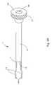
- FIG. 1shows an exemplary plate holding instrument
- FIG. 2Ashows a top view of an exemplary bone plate
- FIG. 2Bshows a side view of an exemplary bone plate
- FIG. 2Cshows a cross sectional view of an exemplary bone plate taken along sectional line 2 C- 2 C of FIG. 2B ;
- FIG. 3shows an exemplary tubular member
- FIG. 4Ashows an exemplary inner sleeve
- FIG. 4Bshows another exemplary embodiment of the inner sleeve
- FIG. 5shows an exemplary rod
- FIG. 6shows a partially exploded view of an exemplary plate holding instrument
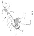
- FIG. 7shows an exemplary plate holding instrument having a handle and the fingers extended
- FIG. 8shows an exemplary plate holding instrument having a handle and the fingers retracted
- FIG. 9shows an exemplary plate holding instrument having a handle and holding an exemplary bone plate
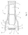
- FIG. 10shows a cross sectional view of the front end of an exemplary plate holding instrument
- FIG. 11shows a cross sectional view of the front end of an exemplary plate holding instrument with the fingers extended over an exemplary bone plate
- FIG. 12shows a cross sectional view of the front end of an exemplary plate holding instrument engaging an exemplary bone plate
- FIG. 13Ashows a cross sectional view of the front end of another exemplary embodiment of the plate holding instrument and another exemplary embodiment of the bone plate;
- FIG. 13Bshows a cross sectional view of the front end of the exemplary plate holding instrument of FIG. 13A engaging the bone plate.
- the present inventionrelates to instrumentation for osteofixation. More particularly, the invention relates to specially configured bone plates and instruments for holding bone plates during osteofixation procedures.
- a plate holding instrument 1allows a user to securely hold a bone plate 2 to the bone while passing drills and screws through the bone plate 2 .
- the plate holding instrument 1is a transbuccal plate holding cannula and the bone plate 2 is a mandible plate.
- a transbuccal plate holding cannulais used to rigidly capture a mandible plate intraorally, to manipulate plate placement, and to accurately pass drills and screws through the cannula into the plate.
- FIG. 1shows a preferred embodiment of the plate holding instrument 1 .
- FIGS. 2A-2Cshow a preferred embodiment of the bone plate 2 .
- the plate holding instrument 1includes a tubular member 3 , an inner sleeve 4 , and a rod 5 .
- a plate 2includes a front surface 20 , a rear surface 21 , and at least one plate hole 22 .
- the plate hole 22extends through the plate 2 from the front surface 20 to the rear surface 21 .
- the periphery of the plate hole 22 on the front surface 20 of the plate 2has a chamfered surface 23 .
- the outer periphery of the bone plate 2 on the rear surface 21includes recesses 25 .
- FIG. 3shows an exemplary tubular member 3 .
- the tubular member 3has a hollow, cylindrical body 30 , a front end 31 , and a rear end 32 .
- the front end 31has a tip opening 33 a , at least two longitudinal slots 34 and at least two recesses 35 (only one is depicted) located around the circumference of the tubular member 3 .
- the outer surface 36 of the tip opening 33 ais chamfered inwardly.
- the slots 34extend from the tip opening 33 a rearward along the longitudinal length of the body 30 of the tubular member 3 .
- the forward surface of the slots 34have ramps 37 that slope radially outward moving forward from the back end toward the front end.
- the recesses 35are aligned with the slots 34 along the longitudinal axis of the tubular member 3 and are located longitudinally forward of the slots 34 .
- the recesses 35extend to the tip of the front end 31 of the tubular member 3 .
- the rear end 32 of the tubular member 3has an annular flange 38 and a rear opening 33 b .
- a passageway 39connects the tip opening 33 a on the front end of the tubular member 3 to the rear opening 33 b.
- FIGS. 4A and 4Bshow exemplary inner sleeves 4 .
- the inner sleeve 4has a hollow, cylindrical body 40 , a front end 41 , and a back end 42 .
- the distal ends of the fingers 43have tips 44 .
- the tips 44are bent radially inward, as shown in FIGS. 4A and 4B .
- the front end 41 of the inner sleeve 4has a front opening 45 and the back end 42 of the inner sleeve 4 has a back opening 46 . As shown in FIGS.
- the back end 42 of the inner sleeve 4has an annular flange 47 .
- the fingers 43are biased toward a closed position and are in substantial longitudinal alignment with the inner sleeve 4 .
- the fingers 43are biased radially outward toward an open position.
- FIG. 5shows and exemplary rod 5 .
- the rod 5is an obturator.
- the rod 5has a body 50 , an annular flange 51 , and a tip 52 .
- the tip 52 of the rod 5tapers to a blunt point.
- FIG. 6shows a preferred assembly of the plate holding instrument 1 .
- the inner sleeve 4is inserted through the rear opening 33 b of the tubular member 3 and fits slidably therein.
- the fingers 43protrude outwardly through the slots 34 of the tubular member 3 , as shown in FIGS. 7 and 11 .
- the fingers 43are biased closed and are forced open by the ramps 37 as the inner sleeve 4 is pressed forward in the tubular member 3 .
- the fingers 43are biased open so that they extend axially outward through the slots 34 as the inner sleeve 4 is pressed forward in the tubular member 3 .
- a spring 6is preferably located between the annular flange 47 of the inner sleeve 4 and the annular flange 38 of the tubular member 3 so that the inner sleeve 4 automatically slides back as it is released.
- the fingers 43are biased closed so that they move toward a closed position as the inner sleeve 4 slides back and off the ramps 37 .
- the fingers 43are biased open and are forced closed by the tubular member 3 as the inner sleeve 4 slides back in to the tubular member 3 .
- Rampsmay be provided on the back side of the slots to facilitate closing of the fingers.
- a handle 7can be attached to the body 30 of the tubular member 3 .
- the handle 7has a body 70 that has an annular opening 71 at an upper end 72 .
- the body 30 of the tubular member 3is slid into the annular opening 71 of the handle 7 and is secured therein.
- an internal spring loaded ball(not shown) and a corresponding mating recess (not shown) may be used to secure the tubular member 3 to the handle 7 .
- the handle 7facilitates manipulation of the plate holding instrument 1 and allows the plate holding instrument 1 to be manipulated with one hand.
- a handle 7may include a ratchet gear mechanism (not shown) to actuate the forward movement of the inner sleeve 4 into the tubular member 3 .
- the ratchet gear mechanismmay include a lever arm having a distal end and a proximal end. The distal end of the lever arm may be in contact with the back end 42 of the inner sleeve 4 , a central portion of the lever arm may be pivotally connected to the handle body 70 , and the distal end may protrude through the handle body 70 to form a trigger, or be mechanically connected to a trigger mechanism.
- the triggermay be actuated to cause the distal end of the lever arm to move the inner sleeve 4 forward into the tubular member 3 in a controlled manner.
- the pivot point between the lever arm and the handle body 70may incorporate a ratchet gear such that the forward movement of the distal end of the lever arm and the back end 42 of the inner sleeve 4 toward the tubular member 3 may be maintained.
- a release mechanismmay be employed to disengage the ratchet gear and allow the distal end of the lever arm and the back end 42 of the inner sleeve 4 to move back away from the tubular member 3 .
- the fingers 43extend axially forward and radially outward through the slots 34 (not shown) of the tubular member 3 .
- the slots 34have ramps 37 that force the fingers 43 , which in one embodiment shown in FIG. 4A are biased closed, to expand radially outward through the slots as the inner sleeve 4 is pressed axially forward.
- the fingers 43are biased open, as shown in the embodiment illustrated in FIG.
- rampsare not required and the slots 34 allow the fingers to extend axially outward as the inner sleeve 4 is pressed forward in the tubular member 3 .
- the radial expansion of the fingers 43allows the fingers 43 to extend over and around the outer periphery of a bone plate 2 .
- the fingers 43retract inwardly into the tubular member 3 .
- the retraction of the fingers 43engages the outer periphery of a bone plate 2 .
- the finger tips 44engage the recesses 35 on the tubular member 3 , and the fingers 43 rest flush against the outer surface of the tubular member 3 .
- the recesses 35help prevent the fingers 43 from snagging tissue as the instrument 1 moves through incisions in the body.
- FIGS. 10-12show a preferred embodiment of the plate holding instrument 1 in operation.
- a bone plate 2is introduced into a patient's body at the site of desired osteofixation.
- the plate holding instrument 1is introduced into the body to manipulate the bone plate 2 and facilitate the fixation of the plate 2 to the bone.
- a rod 5is inserted through the inner sleeve 4 , the tip 52 of the rod 5 protrudes through the tip opening 33 a of the tubular member 3 .
- the protruding tip 52 of the rod 5gives the plate holding instrument 1 a tapered front end that is easier to insert and guide through an incision in the body. Once plate holding instrument 1 is properly positioned within the incision, the rod 5 may be removed from the plate holding instrument 1 .
- the back end 42 (not shown) of the inner sleeve 4is pressed forward to extend the fingers 43 and engage the outer periphery of the bone plate 2 .
- the inner sleeve 4can slide back and the fingers 43 can retract.
- a spring 5is located between the annular flange 47 of the inner sleeve 4 and the annular flange 38 of the tubular member 3 so that the inner sleeve 4 slides back and the fingers 43 retract automatically when the back end 42 of the inner sleeve 4 is released. Further, the use of spring 5 to retract the inner sleeve 4 helps to positively maintain engagement of the plate 2 with the fingers 43 .
- the tips 44 of the fingers 43engage recessed portions 25 on the rear surface 21 of the plate 2 , and the front surface 20 of the plate 2 is moved against the front end 31 of the tubular member 3 .
- the tip opening 33 a of the tubular member 3is brought into contact with the plate 2 such that the chamfered outer surface 36 of the tip opening 33 a rests against the chamfered surface 23 around the periphery of the plate hole 22 .
- drills and screwsfor example, can be passed through the inner sleeve 4 to secure the bone plate 2 to the bone.
- the fingers 43 a of the inner sleeve 4engage the plate 2 through the plate holes 22 at recesses 24 .
- the bone plate 2includes recesses 24 proximate the plate holes 22 and the fingers 43 a extend into the recesses 24 to engage the plate 2 .
- the bone plate 2has a front surface 20 , a rear surface 21 , and at least one plate hole 22 .
- the plate hole 22extends through the plate 2 from the front surface 20 to the rear surface 21 .
- recess 24includes a first portion 24 a and second portion 24 b .
- the first portion 24 a of the recess 24is formed on the front surface 20 of the plate 2 and extends through the plate to the rear surface 21 .
- the second portion 24 b of the recess 24is located adjacent to the rear surface 21 of the plate hole 22 and extends axially outward from a center of the plate hole 22 . As shown, recess 24 extends generally radially outward from the front surface 20 to the rear surface 21 .
- the fingers 43 a of the inner sleeve 4extend longitudinally and radially outward from the tubular member 3 through the tip opening 33 a .
- the fingers 43 aare curved outwardly so that they expand radially outward as they are extended past the end 33 a .
- the tips 44 a of the fingers 43 aare preferably bent radially outward to engage the recesses 24 adjacent to the plate holes 22 as the fingers 43 a extend and expand into the bone plate 2 .
- the plate holding instrument 1 of FIGS. 13A and 13Bis brought into contact with the plate 2 .
- the tip opening 33 a of the tubular member 3contacts the periphery of the plate hole 22 .
- the back end 42 of the inner sleeve 4is pressed forward and the fingers 43 a extend longitudinally and radially outward through the tip opening 33 a of the tubular member 3 .
- the fingers 43 aextend and expand and the tips 44 a of the fingers 43 a engage the recesses 24 to secure the plate 2 .
- drills and screwsmay be introduced to the bone plate 2 through the inner sleeve 4 while the inner sleeve 4 is pressed forward and the fingers 43 a are securing the bone plate 2 .
- the fingers 43 aretract and the plate holding instrument 1 disengages the bone plate 2 .
Landscapes
- Health & Medical Sciences (AREA)
- Orthopedic Medicine & Surgery (AREA)
- Surgery (AREA)
- Life Sciences & Earth Sciences (AREA)
- Heart & Thoracic Surgery (AREA)
- Veterinary Medicine (AREA)
- Engineering & Computer Science (AREA)
- Biomedical Technology (AREA)
- Nuclear Medicine, Radiotherapy & Molecular Imaging (AREA)
- Medical Informatics (AREA)
- Molecular Biology (AREA)
- Animal Behavior & Ethology (AREA)
- General Health & Medical Sciences (AREA)
- Public Health (AREA)
- Neurology (AREA)
- Dentistry (AREA)
- Oral & Maxillofacial Surgery (AREA)
- Surgical Instruments (AREA)
- External Artificial Organs (AREA)
Abstract
Description
Claims (20)
Priority Applications (15)
| Application Number | Priority Date | Filing Date | Title |
|---|---|---|---|
| US11/349,559US7473255B2 (en) | 2006-02-08 | 2006-02-08 | Transbuccal plate holding cannula |
| TW096104360ATWI386183B (en) | 2006-02-08 | 2007-02-07 | Transbuccal plate holding cannula |
| JP2008554300AJP5225863B2 (en) | 2006-02-08 | 2007-02-07 | Cannula holding transbuckle plate |
| BRPI0707712ABRPI0707712B8 (en) | 2006-02-08 | 2007-02-07 | apparatus to contain a bone plate, bone plate and instrumentation for bone fixation |
| AU2007212435AAU2007212435A1 (en) | 2006-02-08 | 2007-02-07 | Transbuccal plate holding cannula |
| CA2641714ACA2641714C (en) | 2006-02-08 | 2007-02-07 | Transbuccal plate holding cannula |
| CA2876440ACA2876440C (en) | 2006-02-08 | 2007-02-07 | Transbuccal plate holding cannula |
| EP07763223.0AEP1981424B1 (en) | 2006-02-08 | 2007-02-07 | Transbuccal plate holding cannula |
| KR1020087018654AKR101433683B1 (en) | 2006-02-08 | 2007-02-07 | Transbuccal plate holding cannula |
| CN2007800037112ACN101374471B (en) | 2006-02-08 | 2007-02-07 | Transbuccal plate holding cannula |
| PCT/US2007/003142WO2007092441A2 (en) | 2006-02-08 | 2007-02-07 | Transbuccal plate holding cannula |
| ZA200806198AZA200806198B (en) | 2006-02-08 | 2008-07-16 | Transbuccal plate holding cannula |
| US12/277,773US8398685B2 (en) | 2006-02-08 | 2008-11-25 | Transbuccal plate holding cannula |
| JP2012211916AJP5628875B2 (en) | 2006-02-08 | 2012-09-26 | Bone plate |
| JP2014087452AJP5860089B2 (en) | 2006-02-08 | 2014-04-21 | Bone plate |
Applications Claiming Priority (1)
| Application Number | Priority Date | Filing Date | Title |
|---|---|---|---|
| US11/349,559US7473255B2 (en) | 2006-02-08 | 2006-02-08 | Transbuccal plate holding cannula |
Related Child Applications (1)
| Application Number | Title | Priority Date | Filing Date |
|---|---|---|---|
| US12/277,773DivisionUS8398685B2 (en) | 2006-02-08 | 2008-11-25 | Transbuccal plate holding cannula |
Publications (2)
| Publication Number | Publication Date |
|---|---|
| US20070213726A1 US20070213726A1 (en) | 2007-09-13 |
| US7473255B2true US7473255B2 (en) | 2009-01-06 |
Family
ID=38330526
Family Applications (2)
| Application Number | Title | Priority Date | Filing Date |
|---|---|---|---|
| US11/349,559Active2027-02-02US7473255B2 (en) | 2006-02-08 | 2006-02-08 | Transbuccal plate holding cannula |
| US12/277,773Active2027-08-26US8398685B2 (en) | 2006-02-08 | 2008-11-25 | Transbuccal plate holding cannula |
Family Applications After (1)
| Application Number | Title | Priority Date | Filing Date |
|---|---|---|---|
| US12/277,773Active2027-08-26US8398685B2 (en) | 2006-02-08 | 2008-11-25 | Transbuccal plate holding cannula |
Country Status (11)
| Country | Link |
|---|---|
| US (2) | US7473255B2 (en) |
| EP (1) | EP1981424B1 (en) |
| JP (3) | JP5225863B2 (en) |
| KR (1) | KR101433683B1 (en) |
| CN (1) | CN101374471B (en) |
| AU (1) | AU2007212435A1 (en) |
| BR (1) | BRPI0707712B8 (en) |
| CA (2) | CA2876440C (en) |
| TW (1) | TWI386183B (en) |
| WO (1) | WO2007092441A2 (en) |
| ZA (1) | ZA200806198B (en) |
Cited By (33)
| Publication number | Priority date | Publication date | Assignee | Title |
|---|---|---|---|---|
| US20080015694A1 (en)* | 2006-01-13 | 2008-01-17 | Clifford Tribus | Spine reduction and stabilization device |
| US20090163963A1 (en)* | 2005-09-26 | 2009-06-25 | Gregory Berrevoets | Apparatus and Method for Implantation of Surgical Devices |
| USD603502S1 (en)* | 2007-12-03 | 2009-11-03 | Orthopedic Development Corporation | Surgical impactor |
| US20090281543A1 (en)* | 2008-05-09 | 2009-11-12 | Skeletal Dynamics Llc | Formable bone plate, clamping apparatus, osteotomy system and method for reconstructing a bone |
| US20100145391A1 (en)* | 2008-12-05 | 2010-06-10 | Kleiner Jeffrey | Apparatus and method of spinal implant and fusion |
| US8088163B1 (en) | 2008-02-06 | 2012-01-03 | Kleiner Jeffrey B | Tools and methods for spinal fusion |
| USD656610S1 (en) | 2009-02-06 | 2012-03-27 | Kleiner Jeffrey B | Spinal distraction instrument |
| US8439932B2 (en) | 2010-05-03 | 2013-05-14 | Biomet Manufacturing Corp. | Submuscular plating system |
| US8685031B2 (en) | 2009-09-18 | 2014-04-01 | Spinal Surgical Strategies, Llc | Bone graft delivery system |
| US8864654B2 (en) | 2010-04-20 | 2014-10-21 | Jeffrey B. Kleiner | Method and apparatus for performing retro peritoneal dissection |
| US8906028B2 (en) | 2009-09-18 | 2014-12-09 | Spinal Surgical Strategies, Llc | Bone graft delivery device and method of using the same |
| USD723682S1 (en) | 2013-05-03 | 2015-03-03 | Spinal Surgical Strategies, Llc | Bone graft delivery tool |
| US9060877B2 (en) | 2009-09-18 | 2015-06-23 | Spinal Surgical Strategies, Llc | Fusion cage with combined biological delivery system |
| US9173694B2 (en) | 2009-09-18 | 2015-11-03 | Spinal Surgical Strategies, Llc | Fusion cage with combined biological delivery system |
| US9186193B2 (en) | 2009-09-18 | 2015-11-17 | Spinal Surgical Strategies, Llc | Fusion cage with combined biological delivery system |
| US9247943B1 (en) | 2009-02-06 | 2016-02-02 | Kleiner Intellectual Property, Llc | Devices and methods for preparing an intervertebral workspace |
| USD750249S1 (en) | 2014-10-20 | 2016-02-23 | Spinal Surgical Strategies, Llc | Expandable fusion cage |
| US9629729B2 (en) | 2009-09-18 | 2017-04-25 | Spinal Surgical Strategies, Llc | Biological delivery system with adaptable fusion cage interface |
| US20170143353A1 (en)* | 2009-05-15 | 2017-05-25 | Globus Medical, Inc. | Screw guide and tissue retractor instrument |
| US9717403B2 (en) | 2008-12-05 | 2017-08-01 | Jeffrey B. Kleiner | Method and apparatus for performing retro peritoneal dissection |
| USD797290S1 (en) | 2015-10-19 | 2017-09-12 | Spinal Surgical Strategies, Llc | Bone graft delivery tool |
| US20190046251A1 (en)* | 2016-03-11 | 2019-02-14 | Jace Medical, Llc | Orthopaedic fixation devices, systems and methods |
| US10245159B1 (en) | 2009-09-18 | 2019-04-02 | Spinal Surgical Strategies, Llc | Bone graft delivery system and method for using same |
| USD853560S1 (en) | 2008-10-09 | 2019-07-09 | Nuvasive, Inc. | Spinal implant insertion device |
| US10945725B2 (en) | 2017-02-06 | 2021-03-16 | Crossroads Extremity Systems, Llc | Implant inserter |
| US10973656B2 (en) | 2009-09-18 | 2021-04-13 | Spinal Surgical Strategies, Inc. | Bone graft delivery system and method for using same |
| US11179149B2 (en) | 2017-02-07 | 2021-11-23 | Crossroads Extremity Systems, Llc | Counter-torque implant |
| US11202626B2 (en) | 2014-07-10 | 2021-12-21 | Crossroads Extremity Systems, Llc | Bone implant with means for multi directional force and means of insertion |
| USD961081S1 (en) | 2020-11-18 | 2022-08-16 | Crossroads Extremity Systems, Llc | Orthopedic implant |
| US11666455B2 (en) | 2009-09-18 | 2023-06-06 | Spinal Surgical Strategies, Inc., A Nevada Corporation | Bone graft delivery devices, systems and kits |
| US11871899B2 (en) | 2013-12-20 | 2024-01-16 | Crossroads Extremity Systems, Llc | Bone plates with dynamic elements |
| US12059183B2 (en) | 2020-07-31 | 2024-08-13 | Crossroads Extremity Systems, Llc | Bone plates with dynamic elements and screws |
| US12279972B2 (en) | 2008-05-22 | 2025-04-22 | Spinal Surgical Strategies, Inc. | Spinal fusion cage system with inserter |
Families Citing this family (91)
| Publication number | Priority date | Publication date | Assignee | Title |
|---|---|---|---|---|
| US8613747B2 (en) | 2004-10-20 | 2013-12-24 | Vertiflex, Inc. | Spacer insertion instrument |
| US8197484B2 (en)* | 2007-04-24 | 2012-06-12 | Depuy Products, Inc. | Assembly for minimally invasive reduction of hip fracture |
| US8801725B2 (en)* | 2008-03-10 | 2014-08-12 | Zimmer Orthobiologics, Inc. | Instruments and methods used when repairing a defect on a tissue surface |
| US8257407B2 (en)* | 2008-04-23 | 2012-09-04 | Aryan Henry E | Bone plate system and method |
| US8932332B2 (en)* | 2008-05-08 | 2015-01-13 | Aesculap Implant Systems, Llc | Minimally invasive spinal stabilization system |
| US8337533B2 (en)* | 2008-06-20 | 2012-12-25 | Osteomed Llc | Locking plate benders |
| US8425573B2 (en)* | 2008-10-24 | 2013-04-23 | The Cleveland Clinic Foundation | Method and system for attaching a plate to a bone |
| US8795340B2 (en)* | 2008-11-07 | 2014-08-05 | Globus Medical, Inc. | Vertical inline plate |
| US9486262B2 (en)* | 2010-01-27 | 2016-11-08 | DePuy Synthes Products, Inc. | System and method for minimally invasive clavicle plate application |
| US9113916B2 (en) | 2010-08-31 | 2015-08-25 | Zimmer, Inc. | Drill bit for osteochondral drilling with guiding element and uses thereof |
| US8435305B2 (en)* | 2010-08-31 | 2013-05-07 | Zimmer, Inc. | Osteochondral graft delivery device and uses thereof |
| US8998988B2 (en)* | 2010-12-29 | 2015-04-07 | Spinal Usa, Inc. | Buttress plate system |
| DE202011107521U1 (en)* | 2011-11-04 | 2011-12-01 | Cival Medical Gmbh | Bone surgical placement instrument and system for applying a bone surgical fastener to a bone plate |
| US9361410B2 (en)* | 2012-05-03 | 2016-06-07 | DePuy Synthes Products, Inc. | Surgical guides from scanned implant data |
| AU2015225580B2 (en)* | 2014-03-07 | 2019-10-10 | DePuy Synthes Products, Inc. | Separable guide instrument for anatomical implant |
| JP2017529886A (en)* | 2014-07-10 | 2017-10-12 | クロスローズ エクストリミティ システムズ リミテッド ライアビリティ カンパニー | Bone implant and means of insertion |
| US20160015426A1 (en) | 2014-07-15 | 2016-01-21 | Treace Medical Concepts, Inc. | Bone positioning and cutting system and method |
| US9687250B2 (en) | 2015-01-07 | 2017-06-27 | Treace Medical Concepts, Inc. | Bone cutting guide systems and methods |
| US10064668B2 (en)* | 2015-02-13 | 2018-09-04 | Kls-Martin, L.P. | Bone plate locking cannula and drill guide assembly |
| WO2016134154A1 (en) | 2015-02-18 | 2016-08-25 | Treace Medical Concepts, Inc. | Pivotable bone cutting guide useful for bone realignment and compression techniques |
| WO2016171747A1 (en)* | 2015-04-23 | 2016-10-27 | Acumed Llc | System for deforming plate members on bone |
| US10653467B2 (en) | 2015-05-06 | 2020-05-19 | Treace Medical Concepts, Inc. | Intra-osseous plate system and method |
| US10849663B2 (en) | 2015-07-14 | 2020-12-01 | Treace Medical Concepts, Inc. | Bone cutting guide systems and methods |
| EP4483824A3 (en) | 2015-07-14 | 2025-03-05 | Treace Medical Concepts, Inc. | Bone positioning guide |
| US9622805B2 (en) | 2015-08-14 | 2017-04-18 | Treace Medical Concepts, Inc. | Bone positioning and preparing guide systems and methods |
| WO2017031020A1 (en) | 2015-08-14 | 2017-02-23 | Treace Medical Concepts, Inc. | Tarsal-metatarsal joint procedure utilizing fulcrum |
| EP4494582A3 (en) | 2015-08-14 | 2025-04-16 | Treace Medical Concepts, Inc. | Tarsal-metatarsal joint procedure utilizing fulcrum |
| US10687874B2 (en) | 2015-08-27 | 2020-06-23 | Globus Medical, Inc | Proximal humeral stabilization system |
| US11076898B2 (en) | 2015-08-27 | 2021-08-03 | Globus Medical, Inc. | Proximal humeral stabilization system |
| US11197682B2 (en) | 2015-08-27 | 2021-12-14 | Globus Medical, Inc. | Proximal humeral stabilization system |
| CA2998481C (en) | 2015-09-18 | 2024-05-14 | Treace Medical Concepts, Inc. | Joint spacer systems and methods |
| DE102015116091B4 (en)* | 2015-09-23 | 2019-05-29 | Karl Leibinger Medizintechnik Gmbh & Co. Kg | Plate holding instrument with snapping or "snap-in" gripping section |
| US10130402B2 (en) | 2015-09-25 | 2018-11-20 | Globus Medical, Inc. | Bone fixation devices having a locking feature |
| US9974581B2 (en) | 2015-11-20 | 2018-05-22 | Globus Medical, Inc. | Expandable intramedullary systems and methods of using the same |
| FR3047658B1 (en)* | 2016-02-15 | 2018-02-09 | Backbone | INTERVERTEBRAL IMPLANT OF DYNAMIC STABILIZATION AND ITS POSITIONING TOOL |
| US9795411B2 (en) | 2016-03-02 | 2017-10-24 | Globus Medical, Inc. | Fixators for bone stabilization and associated systems and methods |
| US10531905B2 (en) | 2016-04-19 | 2020-01-14 | Globus Medical, Inc. | Implantable compression screws |
| US10420596B2 (en) | 2016-08-17 | 2019-09-24 | Globus Medical, Inc. | Volar distal radius stabilization system |
| US11432857B2 (en) | 2016-08-17 | 2022-09-06 | Globus Medical, Inc. | Stabilization systems |
| US10751098B2 (en) | 2016-08-17 | 2020-08-25 | Globus Medical Inc. | Stabilization systems |
| US11331128B2 (en) | 2016-08-17 | 2022-05-17 | Globus Medical Inc. | Distal radius stabilization system |
| US11141204B2 (en) | 2016-08-17 | 2021-10-12 | Globus Medical Inc. | Wrist stabilization systems |
| US11213327B2 (en) | 2016-08-17 | 2022-01-04 | Globus Medical, Inc. | Fracture plates, systems, and methods |
| US10575884B2 (en) | 2016-08-17 | 2020-03-03 | Globus Medical, Inc. | Fracture plates, systems, and methods |
| US10687873B2 (en) | 2016-08-17 | 2020-06-23 | Globus Medical Inc. | Stabilization systems |
| US10383668B2 (en) | 2016-08-17 | 2019-08-20 | Globus Medical, Inc. | Volar distal radius stabilization system |
| US11197701B2 (en) | 2016-08-17 | 2021-12-14 | Globus Medical, Inc. | Stabilization systems |
| US10512470B1 (en) | 2016-08-26 | 2019-12-24 | Treace Medical Concepts, Inc. | Osteotomy procedure for correcting bone misalignment |
| US10299847B2 (en) | 2016-09-22 | 2019-05-28 | Globus Medical, Inc. | Systems and methods for intramedullary nail implantation |
| US10524808B1 (en) | 2016-11-11 | 2020-01-07 | Treace Medical Concepts, Inc. | Devices and techniques for performing an osteotomy procedure on a first metatarsal to correct a bone misalignment |
| EP3562414A2 (en)* | 2016-12-27 | 2019-11-06 | Depuy Synthes Products, Inc. | Bone plate fastening system |
| IT201700002652A1 (en)* | 2017-01-12 | 2018-07-12 | 2B1 S R L | Improved plaque for the synthesis of a bone fracture and kit incorporating this plate. |
| US10939939B1 (en) | 2017-02-26 | 2021-03-09 | Treace Medical Concepts, Inc. | Fulcrum for tarsal-metatarsal joint procedure |
| US10881438B2 (en) | 2017-03-10 | 2021-01-05 | Globus Medical, Inc. | Clavicle fixation system |
| US10905477B2 (en) | 2017-03-13 | 2021-02-02 | Globus Medical, Inc. | Bone stabilization systems |
| US10368928B2 (en) | 2017-03-13 | 2019-08-06 | Globus Medical, Inc. | Bone stabilization systems |
| US11096730B2 (en) | 2017-09-13 | 2021-08-24 | Globus Medical Inc. | Bone stabilization systems |
| US10856920B2 (en) | 2017-09-13 | 2020-12-08 | Globus Medical Inc. | Bone stabilization systems |
| US12318122B2 (en) | 2017-09-13 | 2025-06-03 | Globus Medical, Inc. | Bone stabilization systems |
| US11224468B2 (en) | 2018-03-02 | 2022-01-18 | Globus Medical, Inc. | Distal tibial plating system |
| US11071570B2 (en) | 2018-03-02 | 2021-07-27 | Globus Medical, Inc. | Distal tibial plating system |
| US11141172B2 (en) | 2018-04-11 | 2021-10-12 | Globus Medical, Inc. | Method and apparatus for locking a drill guide in a polyaxial hole |
| US11596443B2 (en) | 2018-07-11 | 2023-03-07 | Treace Medical Concepts, Inc. | Compressor-distractor for angularly realigning bone portions |
| US11583323B2 (en) | 2018-07-12 | 2023-02-21 | Treace Medical Concepts, Inc. | Multi-diameter bone pin for installing and aligning bone fixation plate while minimizing bone damage |
| CN109172000A (en)* | 2018-10-17 | 2019-01-11 | 董延召 | Femur punches locating guider |
| US11202663B2 (en) | 2019-02-13 | 2021-12-21 | Globus Medical, Inc. | Proximal humeral stabilization systems and methods thereof |
| US11607250B2 (en) | 2019-02-13 | 2023-03-21 | Treace Medical Concepts, Inc. | Tarsal-metatarsal joint procedure utilizing compressor-distractor and instrument providing sliding surface |
| US11571248B2 (en) | 2019-03-19 | 2023-02-07 | Orthoalignment, Llc | Bone implant and method for treating long bone angular deformities |
| CA3146564A1 (en) | 2019-08-07 | 2021-02-11 | Jason May | Bi-planar instrument for bone cutting and joint realignment procedure |
| KR102314563B1 (en)* | 2019-08-29 | 2021-10-20 | 주식회사 제일메디칼코퍼레이션 | Fixing holder for medical plate |
| US11793558B2 (en)* | 2019-08-30 | 2023-10-24 | K2M, Inc. | All in one plate holder and spring loaded awl |
| US11889998B1 (en) | 2019-09-12 | 2024-02-06 | Treace Medical Concepts, Inc. | Surgical pin positioning lock |
| US11890039B1 (en) | 2019-09-13 | 2024-02-06 | Treace Medical Concepts, Inc. | Multi-diameter K-wire for orthopedic applications |
| US11986251B2 (en) | 2019-09-13 | 2024-05-21 | Treace Medical Concepts, Inc. | Patient-specific osteotomy instrumentation |
| US12185995B2 (en) | 2019-10-09 | 2025-01-07 | Globus Medical, Inc. | Bone stabilization systems |
| US11129627B2 (en) | 2019-10-30 | 2021-09-28 | Globus Medical, Inc. | Method and apparatus for inserting a bone plate |
| US11723647B2 (en) | 2019-12-17 | 2023-08-15 | Globus Medical, Inc. | Syndesmosis fixation assembly |
| JP7368243B2 (en)* | 2020-01-17 | 2023-10-24 | メイラ株式会社 | Bone plate bending method, bending tools, and bending tool set |
| WO2021155269A1 (en) | 2020-01-31 | 2021-08-05 | Treace Medical Concepts, Inc. | Metatarsophalangeal joint preparation and metatarsal realignment for fusion |
| US11559341B2 (en) | 2020-02-25 | 2023-01-24 | Aesculap Ag | Surgical instrumentation for cervical-occipito fixation |
| AU2021275140A1 (en) | 2020-05-19 | 2023-02-02 | Treace Medical Concepts, Inc. | Devices and techniques for treating metatarsus adductus |
| US12161371B2 (en) | 2021-01-18 | 2024-12-10 | Treace Medical Concepts, Inc. | Contoured bone plate with locking screw for bone compression, particularly across a tarsometatarsal joint |
| WO2023059482A1 (en)* | 2021-10-04 | 2023-04-13 | Smith & Nephew, Inc. | Bone alignment system and method |
| US20230285116A1 (en)* | 2021-12-02 | 2023-09-14 | DePuy Synthes Products, Inc. | Compression/neutral drill guide sleeve |
| US12064150B2 (en) | 2022-01-19 | 2024-08-20 | Globus Medical Inc. | System and method for treating bone fractures |
| USD1075012S1 (en) | 2022-02-23 | 2025-05-13 | Treace Medical Concepts, Inc. | Metatarsal lateral release instrument |
| USD1079011S1 (en) | 2022-02-23 | 2025-06-10 | Treace Medical Concepts, Inc. | Metatarsal cut guide with parallel cut faces |
| USD1057155S1 (en) | 2022-02-23 | 2025-01-07 | Treace Medical Concepts, Inc. | Lesser metatarsal cut guide with parallel cut faces |
| USD1051382S1 (en) | 2022-02-23 | 2024-11-12 | Treace Medical Concepts, Inc. | Lesser metatarsal cut guide |
| USD1068077S1 (en) | 2023-02-08 | 2025-03-25 | Treace Medical Concepts, Inc. | Orthopedic rasp for preparing an intercuneiform joint |
| USD1068078S1 (en) | 2023-02-08 | 2025-03-25 | Treace Medical Concepts, Inc. | Handle for an orthopedic instrument |
Citations (17)
| Publication number | Priority date | Publication date | Assignee | Title |
|---|---|---|---|---|
| US2549731A (en)* | 1944-12-18 | 1951-04-17 | Vincent E Wattley | Flexible test prod |
| US2631584A (en)* | 1948-07-22 | 1953-03-17 | Alfred T Purificato | Fracture securing instrument |
| US2933114A (en) | 1957-09-16 | 1960-04-19 | Agnar F Bystrom | Screw-holding screw driver |
| US5423826A (en) | 1993-02-05 | 1995-06-13 | Danek Medical, Inc. | Anterior cervical plate holder/drill guide and method of use |
| US5667513A (en)* | 1995-06-07 | 1997-09-16 | Smith & Nephew Dyonics Inc. | Soft tissue anchor delivery apparatus |
| US5755721A (en) | 1996-03-13 | 1998-05-26 | Synthes | Plate holding drill guide and trocar and method of holding a plate |
| US5782747A (en)* | 1996-04-22 | 1998-07-21 | Zimmon Science Corporation | Spring based multi-purpose medical instrument |
| US5782830A (en)* | 1995-10-16 | 1998-07-21 | Sdgi Holdings, Inc. | Implant insertion device |
| US6319257B1 (en)* | 1999-12-20 | 2001-11-20 | Kinamed, Inc. | Inserter assembly |
| US6436103B1 (en) | 2000-12-21 | 2002-08-20 | Loubert Suddaby | Drill guide and plate attachment mechanism for orthopedic plating |
| WO2003015650A1 (en) | 2001-08-21 | 2003-02-27 | Depuy Products, Inc. | Method and apparatus for percutaneously securing a bone screw and a bone plate to a bone of a patient |
| US6648888B1 (en) | 2002-09-06 | 2003-11-18 | Endius Incorporated | Surgical instrument for moving a vertebra |
| US20040097937A1 (en) | 2002-11-19 | 2004-05-20 | Sandi Pike | Orthopedic bone plate |
| USRE38684E1 (en) | 1997-07-01 | 2005-01-04 | Synthes Ag Chur | Freely separable surgical drill guide and plate |
| US20050038444A1 (en) | 2003-08-13 | 2005-02-17 | Binder Lawrence J. | Quick-release drill-guide assembly for bone-plate |
| US20060036254A1 (en)* | 2004-08-10 | 2006-02-16 | Roy Lim | Reducing instrument for spinal surgery |
| US7001333B2 (en)* | 2000-12-20 | 2006-02-21 | Hamel Ross J | Surgical retractor system |
Family Cites Families (14)
| Publication number | Priority date | Publication date | Assignee | Title |
|---|---|---|---|---|
| US2108206A (en)* | 1937-03-09 | 1938-02-15 | Lillian Pearl Mecker | Tenaculum |
| US5066296A (en)* | 1989-02-02 | 1991-11-19 | Pfizer Hopsital Products Group, Inc. | Apparatus for treating a fracture |
| US6017345A (en)* | 1997-05-09 | 2000-01-25 | Spinal Innovations, L.L.C. | Spinal fixation plate |
| FR2784571B1 (en)* | 1998-10-19 | 2001-02-02 | Scient X | ANTERIOR OSTEOSYNTHESIS PLATE FOR LUMBAR OR LUMBAR / SACRED VERTEBRES AND INSTRUMENT FOR POSITIONING SUCH A PLATE |
| CN1172634C (en) | 1999-09-13 | 2004-10-27 | 库尔斯恩蒂斯股份公司 | Bone plating system |
| US6293949B1 (en)* | 2000-03-01 | 2001-09-25 | Sdgi Holdings, Inc. | Superelastic spinal stabilization system and method |
| US6342057B1 (en)* | 2000-04-28 | 2002-01-29 | Synthes (Usa) | Remotely aligned surgical drill guide |
| CA2354747A1 (en)* | 2000-08-08 | 2002-02-08 | Depuy Acromed, Inc. | Spinal rod/plate locking mechanisms and surgical methods |
| JP4283665B2 (en)* | 2001-06-04 | 2009-06-24 | ウォーソー・オーソペディック・インコーポレーテッド | Dynamic plate for anterior cervical spine with movable segments |
| CA2443429C (en)* | 2001-06-04 | 2010-08-10 | Gary Karlin Michelson | Anterior cervical plate system having vertebral body engaging anchors, connecting plate, and method for installation thereof |
| US7625378B2 (en)* | 2002-09-30 | 2009-12-01 | Warsaw Orthopedic, Inc. | Devices and methods for securing a bone plate to a bony segment |
| BRPI0408769A (en)* | 2003-03-26 | 2006-03-28 | Swiss Orthopedic Solutions Sa | lock bone plate |
| US7179261B2 (en)* | 2003-12-16 | 2007-02-20 | Depuy Spine, Inc. | Percutaneous access devices and bone anchor assemblies |
| ATE441376T1 (en)* | 2003-12-17 | 2009-09-15 | Depuy Spine Inc | INSTRUMENTS AND PROCEDURES FOR BONE ANCHOR PROCEDURES AND SPINAL BAR REDUCTION |
- 2006
- 2006-02-08USUS11/349,559patent/US7473255B2/enactiveActive
- 2007
- 2007-02-07KRKR1020087018654Apatent/KR101433683B1/enactiveActive
- 2007-02-07WOPCT/US2007/003142patent/WO2007092441A2/enactiveApplication Filing
- 2007-02-07JPJP2008554300Apatent/JP5225863B2/enactiveActive
- 2007-02-07TWTW096104360Apatent/TWI386183B/enactive
- 2007-02-07AUAU2007212435Apatent/AU2007212435A1/ennot_activeAbandoned
- 2007-02-07CACA2876440Apatent/CA2876440C/enactiveActive
- 2007-02-07BRBRPI0707712Apatent/BRPI0707712B8/enactiveIP Right Grant
- 2007-02-07EPEP07763223.0Apatent/EP1981424B1/enactiveActive
- 2007-02-07CACA2641714Apatent/CA2641714C/enactiveActive
- 2007-02-07CNCN2007800037112Apatent/CN101374471B/enactiveActive
- 2008
- 2008-07-16ZAZA200806198Apatent/ZA200806198B/enunknown
- 2008-11-25USUS12/277,773patent/US8398685B2/enactiveActive
- 2012
- 2012-09-26JPJP2012211916Apatent/JP5628875B2/enactiveActive
- 2014
- 2014-04-21JPJP2014087452Apatent/JP5860089B2/enactiveActive
Patent Citations (20)
| Publication number | Priority date | Publication date | Assignee | Title |
|---|---|---|---|---|
| US2549731A (en)* | 1944-12-18 | 1951-04-17 | Vincent E Wattley | Flexible test prod |
| US2631584A (en)* | 1948-07-22 | 1953-03-17 | Alfred T Purificato | Fracture securing instrument |
| US2933114A (en) | 1957-09-16 | 1960-04-19 | Agnar F Bystrom | Screw-holding screw driver |
| US5423826A (en) | 1993-02-05 | 1995-06-13 | Danek Medical, Inc. | Anterior cervical plate holder/drill guide and method of use |
| US5667513A (en)* | 1995-06-07 | 1997-09-16 | Smith & Nephew Dyonics Inc. | Soft tissue anchor delivery apparatus |
| US5782830A (en)* | 1995-10-16 | 1998-07-21 | Sdgi Holdings, Inc. | Implant insertion device |
| US5755721A (en) | 1996-03-13 | 1998-05-26 | Synthes | Plate holding drill guide and trocar and method of holding a plate |
| US5782747A (en)* | 1996-04-22 | 1998-07-21 | Zimmon Science Corporation | Spring based multi-purpose medical instrument |
| USRE38684E1 (en) | 1997-07-01 | 2005-01-04 | Synthes Ag Chur | Freely separable surgical drill guide and plate |
| US6319257B1 (en)* | 1999-12-20 | 2001-11-20 | Kinamed, Inc. | Inserter assembly |
| US7001333B2 (en)* | 2000-12-20 | 2006-02-21 | Hamel Ross J | Surgical retractor system |
| US6436103B1 (en) | 2000-12-21 | 2002-08-20 | Loubert Suddaby | Drill guide and plate attachment mechanism for orthopedic plating |
| WO2003015650A1 (en) | 2001-08-21 | 2003-02-27 | Depuy Products, Inc. | Method and apparatus for percutaneously securing a bone screw and a bone plate to a bone of a patient |
| US6916323B2 (en)* | 2001-08-21 | 2005-07-12 | Depuy Products, Inc. | Method and apparatus for percutaneously securing a bone screw and a bone plate to a bone of a patient |
| US6648888B1 (en) | 2002-09-06 | 2003-11-18 | Endius Incorporated | Surgical instrument for moving a vertebra |
| US20040097937A1 (en) | 2002-11-19 | 2004-05-20 | Sandi Pike | Orthopedic bone plate |
| US20050038444A1 (en) | 2003-08-13 | 2005-02-17 | Binder Lawrence J. | Quick-release drill-guide assembly for bone-plate |
| US20050137606A1 (en) | 2003-08-13 | 2005-06-23 | Binder Lawrence J.Jr. | Quick-release drill guide assembly for bone plate |
| US7357804B2 (en)* | 2003-08-13 | 2008-04-15 | Synthes (U.S.A.) | Quick-release drill-guide assembly for bone-plate |
| US20060036254A1 (en)* | 2004-08-10 | 2006-02-16 | Roy Lim | Reducing instrument for spinal surgery |
Cited By (64)
| Publication number | Priority date | Publication date | Assignee | Title |
|---|---|---|---|---|
| US8343165B2 (en)* | 2005-09-26 | 2013-01-01 | Pioneer Surgical Technology, Inc. | Apparatus and method for implantation of surgical devices |
| US20090163963A1 (en)* | 2005-09-26 | 2009-06-25 | Gregory Berrevoets | Apparatus and Method for Implantation of Surgical Devices |
| US20080015694A1 (en)* | 2006-01-13 | 2008-01-17 | Clifford Tribus | Spine reduction and stabilization device |
| US8430929B2 (en)* | 2006-01-13 | 2013-04-30 | Clifford Tribus | Spine reduction and stabilization device |
| USD603502S1 (en)* | 2007-12-03 | 2009-11-03 | Orthopedic Development Corporation | Surgical impactor |
| US8277510B2 (en) | 2008-02-06 | 2012-10-02 | Kleiner Intellectual Property, Llc | Tools and methods for spinal fusion |
| USD700322S1 (en) | 2008-02-06 | 2014-02-25 | Jeffrey B. Kleiner | Intervertebral surgical tool |
| US8715355B2 (en) | 2008-02-06 | 2014-05-06 | Nuvasive, Inc. | Spinal fusion cage with removable planar elements |
| US9439782B2 (en) | 2008-02-06 | 2016-09-13 | Jeffrey B. Kleiner | Spinal fusion cage system with inserter |
| US8292960B2 (en) | 2008-02-06 | 2012-10-23 | Kleiner Intellectual Property, Llc | Spinal fusion cage with removable planar elements |
| US8088163B1 (en) | 2008-02-06 | 2012-01-03 | Kleiner Jeffrey B | Tools and methods for spinal fusion |
| US10179054B2 (en) | 2008-02-06 | 2019-01-15 | Jeffrey B. Kleiner | Spinal fusion cage system with inserter |
| US11129730B2 (en) | 2008-02-06 | 2021-09-28 | Spinal Surgical Strategies, Inc., a Nevada corpora | Spinal fusion cage system with inserter |
| US8808305B2 (en) | 2008-02-06 | 2014-08-19 | Jeffrey B. Kleiner | Spinal fusion cage system with inserter |
| USD696399S1 (en) | 2008-02-06 | 2013-12-24 | Kleiner Intellectual Property, Llc | Spinal distraction instrument |
| US20090281543A1 (en)* | 2008-05-09 | 2009-11-12 | Skeletal Dynamics Llc | Formable bone plate, clamping apparatus, osteotomy system and method for reconstructing a bone |
| US9622799B2 (en)* | 2008-05-09 | 2017-04-18 | Skeletal Dynamics, Llc. | Formable bone plate, clamping apparatus, osteotomy system and method for reconstructing a bone |
| US12279972B2 (en) | 2008-05-22 | 2025-04-22 | Spinal Surgical Strategies, Inc. | Spinal fusion cage system with inserter |
| USD853560S1 (en) | 2008-10-09 | 2019-07-09 | Nuvasive, Inc. | Spinal implant insertion device |
| US20100145391A1 (en)* | 2008-12-05 | 2010-06-10 | Kleiner Jeffrey | Apparatus and method of spinal implant and fusion |
| US9427264B2 (en) | 2008-12-05 | 2016-08-30 | Jeffrey KLEINER | Apparatus and method of spinal implant and fusion |
| US8870882B2 (en) | 2008-12-05 | 2014-10-28 | Jeffrey KLEINER | Apparatus and method of spinal implant and fusion |
| US10617293B2 (en) | 2008-12-05 | 2020-04-14 | Jeffrey B. Kleiner | Method and apparatus for performing retro peritoneal dissection |
| US9717403B2 (en) | 2008-12-05 | 2017-08-01 | Jeffrey B. Kleiner | Method and apparatus for performing retro peritoneal dissection |
| US9861496B2 (en) | 2008-12-05 | 2018-01-09 | Jeffrey B. Kleiner | Apparatus and method of spinal implant and fusion |
| US8366748B2 (en) | 2008-12-05 | 2013-02-05 | Kleiner Jeffrey | Apparatus and method of spinal implant and fusion |
| US10201355B2 (en) | 2009-02-06 | 2019-02-12 | Kleiner Intellectual Property, Llc | Angled surgical tool for removing tissue from within an intervertebral space |
| US9247943B1 (en) | 2009-02-06 | 2016-02-02 | Kleiner Intellectual Property, Llc | Devices and methods for preparing an intervertebral workspace |
| US9826988B2 (en) | 2009-02-06 | 2017-11-28 | Kleiner Intellectual Property, Llc | Devices and methods for preparing an intervertebral workspace |
| USD667542S1 (en) | 2009-02-06 | 2012-09-18 | Kleiner Jeffrey B | Spinal distraction instrument |
| USD656610S1 (en) | 2009-02-06 | 2012-03-27 | Kleiner Jeffrey B | Spinal distraction instrument |
| US11253274B2 (en)* | 2009-05-15 | 2022-02-22 | Globus Mediccal, Inc. | Screw guide and tissue retractor instrument |
| US20170143353A1 (en)* | 2009-05-15 | 2017-05-25 | Globus Medical, Inc. | Screw guide and tissue retractor instrument |
| US8685031B2 (en) | 2009-09-18 | 2014-04-01 | Spinal Surgical Strategies, Llc | Bone graft delivery system |
| US10973656B2 (en) | 2009-09-18 | 2021-04-13 | Spinal Surgical Strategies, Inc. | Bone graft delivery system and method for using same |
| US12167971B2 (en) | 2009-09-18 | 2024-12-17 | Spinal Surgical Strategies, Inc. | Bone graft delivery devices, systems and kits |
| US12053393B2 (en) | 2009-09-18 | 2024-08-06 | Spinal Surgical Strategies, Inc. | Bone graft delivery system and method for use |
| US9186193B2 (en) | 2009-09-18 | 2015-11-17 | Spinal Surgical Strategies, Llc | Fusion cage with combined biological delivery system |
| US9173694B2 (en) | 2009-09-18 | 2015-11-03 | Spinal Surgical Strategies, Llc | Fusion cage with combined biological delivery system |
| US10195053B2 (en) | 2009-09-18 | 2019-02-05 | Spinal Surgical Strategies, Llc | Bone graft delivery system and method for using same |
| US9060877B2 (en) | 2009-09-18 | 2015-06-23 | Spinal Surgical Strategies, Llc | Fusion cage with combined biological delivery system |
| US11666455B2 (en) | 2009-09-18 | 2023-06-06 | Spinal Surgical Strategies, Inc., A Nevada Corporation | Bone graft delivery devices, systems and kits |
| US10245159B1 (en) | 2009-09-18 | 2019-04-02 | Spinal Surgical Strategies, Llc | Bone graft delivery system and method for using same |
| US11660208B2 (en) | 2009-09-18 | 2023-05-30 | Spinal Surgical Strategies, Inc. | Bone graft delivery system and method for using same |
| US8906028B2 (en) | 2009-09-18 | 2014-12-09 | Spinal Surgical Strategies, Llc | Bone graft delivery device and method of using the same |
| US8709088B2 (en) | 2009-09-18 | 2014-04-29 | Spinal Surgical Strategies, Llc | Fusion cage with combined biological delivery system |
| US9629729B2 (en) | 2009-09-18 | 2017-04-25 | Spinal Surgical Strategies, Llc | Biological delivery system with adaptable fusion cage interface |
| US8864654B2 (en) | 2010-04-20 | 2014-10-21 | Jeffrey B. Kleiner | Method and apparatus for performing retro peritoneal dissection |
| US8439932B2 (en) | 2010-05-03 | 2013-05-14 | Biomet Manufacturing Corp. | Submuscular plating system |
| USD723682S1 (en) | 2013-05-03 | 2015-03-03 | Spinal Surgical Strategies, Llc | Bone graft delivery tool |
| US11871899B2 (en) | 2013-12-20 | 2024-01-16 | Crossroads Extremity Systems, Llc | Bone plates with dynamic elements |
| US11202626B2 (en) | 2014-07-10 | 2021-12-21 | Crossroads Extremity Systems, Llc | Bone implant with means for multi directional force and means of insertion |
| US11998191B2 (en) | 2014-07-10 | 2024-06-04 | Crossroads Extremity Systems, Llc | Bone implant with means for multi directional force and means of insertion |
| US11284887B2 (en) | 2014-07-10 | 2022-03-29 | Crossroads Extremity Systems, Llc | Bone implant with means for multi directional force and means of insertion |
| USD750249S1 (en) | 2014-10-20 | 2016-02-23 | Spinal Surgical Strategies, Llc | Expandable fusion cage |
| USD797290S1 (en) | 2015-10-19 | 2017-09-12 | Spinal Surgical Strategies, Llc | Bone graft delivery tool |
| US11490935B2 (en) | 2016-03-11 | 2022-11-08 | Jace Medical, Llc | Orthopaedic fixation devices, systems and methods |
| US20190046251A1 (en)* | 2016-03-11 | 2019-02-14 | Jace Medical, Llc | Orthopaedic fixation devices, systems and methods |
| US10758290B2 (en)* | 2016-03-11 | 2020-09-01 | Jace Medical, Llc | Orthopaedic fixation devices, systems and methods |
| US11864753B2 (en) | 2017-02-06 | 2024-01-09 | Crossroads Extremity Systems, Llc | Implant inserter |
| US10945725B2 (en) | 2017-02-06 | 2021-03-16 | Crossroads Extremity Systems, Llc | Implant inserter |
| US11179149B2 (en) | 2017-02-07 | 2021-11-23 | Crossroads Extremity Systems, Llc | Counter-torque implant |
| US12059183B2 (en) | 2020-07-31 | 2024-08-13 | Crossroads Extremity Systems, Llc | Bone plates with dynamic elements and screws |
| USD961081S1 (en) | 2020-11-18 | 2022-08-16 | Crossroads Extremity Systems, Llc | Orthopedic implant |
Also Published As
| Publication number | Publication date |
|---|---|
| US20090076556A1 (en) | 2009-03-19 |
| BRPI0707712B1 (en) | 2018-06-19 |
| EP1981424A2 (en) | 2008-10-22 |
| ZA200806198B (en) | 2009-07-29 |
| KR20080092394A (en) | 2008-10-15 |
| US8398685B2 (en) | 2013-03-19 |
| CA2876440C (en) | 2017-02-28 |
| WO2007092441A2 (en) | 2007-08-16 |
| KR101433683B1 (en) | 2014-08-25 |
| TW200800092A (en) | 2008-01-01 |
| CA2641714C (en) | 2015-03-31 |
| JP5628875B2 (en) | 2014-11-19 |
| CN101374471B (en) | 2012-05-23 |
| BRPI0707712B8 (en) | 2021-06-22 |
| BRPI0707712A2 (en) | 2011-05-10 |
| EP1981424B1 (en) | 2017-11-22 |
| CA2641714A1 (en) | 2007-08-16 |
| US20070213726A1 (en) | 2007-09-13 |
| JP5860089B2 (en) | 2016-02-16 |
| TWI386183B (en) | 2013-02-21 |
| JP2012250095A (en) | 2012-12-20 |
| CN101374471A (en) | 2009-02-25 |
| CA2876440A1 (en) | 2007-08-16 |
| JP2009525813A (en) | 2009-07-16 |
| JP2014184237A (en) | 2014-10-02 |
| AU2007212435A1 (en) | 2007-08-16 |
| WO2007092441A3 (en) | 2007-12-21 |
| JP5225863B2 (en) | 2013-07-03 |
Similar Documents
| Publication | Publication Date | Title |
|---|---|---|
| US7473255B2 (en) | Transbuccal plate holding cannula | |
| US7001333B2 (en) | Surgical retractor system | |
| JP4220237B2 (en) | Universal handle for surgical devices | |
| JP2015531654A (en) | Multi-hole drill sleeve with protective sleeve | |
| CN115052536B (en) | Universal Drill Guide System | |
| JP2007501063A5 (en) | ||
| KR20060123057A (en) | Drill guide assembly for bone fixation | |
| US20130030478A1 (en) | Anchor wire system and method | |
| US20190223930A1 (en) | Adaptor for use with a driver, a drill, and a cannula for drilling into bone | |
| US7887540B2 (en) | Device for drilling or for inserting implants |
Legal Events
| Date | Code | Title | Description |
|---|---|---|---|
| AS | Assignment | Owner name:SYNTHES (USA), PENNSYLVANIA Free format text:ASSIGNMENT OF ASSIGNORS INTEREST;ASSIGNORS:GRIFFITHS, BRYAN JAMES;HAMEL, ROSS JONATHAN;CICCONE, PAUL CHRISTOPHER;AND OTHERS;REEL/FRAME:017724/0183;SIGNING DATES FROM 20060504 TO 20060515 | |
| AS | Assignment | Owner name:HFSC COMPANY, PENNSYLVANIA Free format text:ASSIGNMENT OF ASSIGNORS INTEREST;ASSIGNOR:SYNTHES (USA);REEL/FRAME:017734/0097 Effective date:20060515 | |
| AS | Assignment | Owner name:SYNTHES (USA), PENNSYLVANIA Free format text:ASSIGNMENT OF ASSIGNORS INTEREST;ASSIGNOR:HFSC COMPANY;REEL/FRAME:018404/0449 Effective date:20061017 | |
| AS | Assignment | Owner name:SYNTHES GMBH, SWITZERLAND Free format text:ASSIGNMENT OF ASSIGNORS INTEREST;ASSIGNOR:SYNTHES (U.S.A.);REEL/FRAME:021582/0649 Effective date:20070207 | |
| FEPP | Fee payment procedure | Free format text:PAYOR NUMBER ASSIGNED (ORIGINAL EVENT CODE: ASPN); ENTITY STATUS OF PATENT OWNER: LARGE ENTITY | |
| STCF | Information on status: patent grant | Free format text:PATENTED CASE | |
| AS | Assignment | Owner name:SYNTHES USA, LLC, PENNSYLVANIA Free format text:CHANGE OF NAME;ASSIGNOR:SYNTHES (U.S.A.);REEL/FRAME:022214/0552 Effective date:20081223 Owner name:SYNTHES USA, LLC,PENNSYLVANIA Free format text:CHANGE OF NAME;ASSIGNOR:SYNTHES (U.S.A.);REEL/FRAME:022214/0552 Effective date:20081223 | |
| FPAY | Fee payment | Year of fee payment:4 | |
| FPAY | Fee payment | Year of fee payment:8 | |
| MAFP | Maintenance fee payment | Free format text:PAYMENT OF MAINTENANCE FEE, 12TH YEAR, LARGE ENTITY (ORIGINAL EVENT CODE: M1553); ENTITY STATUS OF PATENT OWNER: LARGE ENTITY Year of fee payment:12 |