US7472374B1 - System and method for using blueprints to provide a traceable software solution for an enterprise - Google Patents
System and method for using blueprints to provide a traceable software solution for an enterpriseDownload PDFInfo
- Publication number
- US7472374B1 US7472374B1US10/731,846US73184603AUS7472374B1US 7472374 B1US7472374 B1US 7472374B1US 73184603 AUS73184603 AUS 73184603AUS 7472374 B1US7472374 B1US 7472374B1
- Authority
- US
- United States
- Prior art keywords
- software
- business
- blueprint
- relationship
- enterprise
- Prior art date
- Legal status (The legal status is an assumption and is not a legal conclusion. Google has not performed a legal analysis and makes no representation as to the accuracy of the status listed.)
- Expired - Fee Related, expires
Links
Images


Classifications
- G—PHYSICS
- G06—COMPUTING OR CALCULATING; COUNTING
- G06F—ELECTRIC DIGITAL DATA PROCESSING
- G06F8/00—Arrangements for software engineering
- G06F8/10—Requirements analysis; Specification techniques
Definitions
- the present inventionrelates generally to the field of software development. More particularly, the invention provides a technique for using a blueprint to provide a software solution for an enterprise.
- Many enterprisesuse software to perform various tasks in furtherance of the business of the enterprise.
- an airlinemay use such software to receive reservation requests from customers and travel agents.
- the airlinemay use business software to track planes, schedule flight crews, arrange for in-flight meals, order fuel and monitor parts inventory.
- software employed by an enterpriseis customized to one degree or another.
- softwaree.g., an airline reservation system
- the softwaremay begin as an off-the-shelf product, and then undergo some level of modification.
- software that was custom-builthas undergone modifications and updates to bring it in line with current requirements.
- Customized softwareis associated with at least two problems. First, customization is labor-intensive, and thus any customization of software is expensive. Second, customizations are often poorly documented, thus making it difficult to maintain the software, or make further customizations to it. Often, attempts to modify customized software produce unintended results, which is partly due to the fact that there is no structured way to connect the implementation of the software with the original goals that the software was intended to accomplish.
- Legacy systemsare typically examples of custom software that is difficult to modify. Even legacy systems that were not custom-built share many of the problems of custom software, because they may be poorly documented.
- a legacy systemis an existing system within a company that continues to be used despite being out-of-date, incompatible with current systems, or otherwise undesirable. Generally, legacy systems tend to be difficult and expensive to modify and unnecessarily large. Thus, legacy systems typically continue to be used despite such shortcomings because the cost of replacing or redesigning the system may be prohibitive. As a result, the company is forced to trade-off a certain level of competitiveness relative to its more modern competitors because of the expense of replacing a legacy system.
- Legacy systemsare often difficult and expensive to update.
- the software for such systemsis written in old computer languages and may have been custom-made for the company.
- any attempts to further update the softwaremay require the company to obtain assistance from the original vendor, who may have institutional knowledge of the company's software.
- the original vendormay be very expensive, unavailable or even out of business.
- the companymay have another vendor update the software, which will invariably require in-depth analysis of the software before a programmer can become familiar enough with the software to implement an update.
- the additional effort required to perform an update to a legacy systemalso increases the monetary costs associated with the update.
- the softwaremay be proprietary, so the company is forced to deal with a vendor who effectively has a monopoly over the software and who can therefore charge higher prices.
- Legacy systemsas well as newer conventional business software systems, often lack adequate documentation to enable a programmer to understand the system and to determine which other systems, if any, might be affected by a change.
- software in one part of a systemmay have been written specifically to run on a certain type of computer. Without sufficient documentation, a programmer intending to run the software on a different type of computer may have great difficulty determining which parts of the software code were computer-specific. Therefore, the added time required for the programmer to determine which parts of the software need to be changed adds to the costs involved with the change.
- the programmermay also be unaware that a change to the software in one system may have an effect on another system.
- another systemthat is either within or outside the company may communicate with the software that is running on the original computer by using a computer-specific software protocol.
- the other systemmay no longer be able to communicate with the software.
- the programmermay not know that a problem exists until the change is implemented and the systems can no longer communicate, which again adversely affects the costs of the software change.
- any software applicationsuch as an application that is used as a business software system—is a set of instructions that can be followed by a computer to perform one or more tasks.
- a software applicationwas designed by identifying the task(s) to be performed and writing instructions to perform those tasks in a programming language, such as C or C++.
- the disadvantage to this traditional approachis that it requires the software developer to model the development process in terms of the low-level actions that a computer can be instructed to perform, rather than in terms of the contemplated use of the software by actual business users.
- the software to be developedis an organization-wide scheduling system for a company
- the traditional approach to software developmentmay require the developer to model the problem in terms of how calendars are represented as data structures and manipulated arithmetically, how users are uniquely identified within the system, etc.
- This type of model for the softwareis at a much “lower-level” than the business problem that the software is intended to solve.
- RATIONAL ROSEvisual modeling tool from Rational Software Corporation
- RATIONAL ROSEinstead of modeling the requirements for software in terms of the basic actions to be performed by a computer, a software developer can abstract the software under development in terms of “use cases” and object models.
- a “use case”is an instance of the use of the software by an actor. For example, in the scheduling system mentioned above, a use case might be a calendar owner's scheduling of a personal appointment on his or her calendar. Having identified one or more such use cases, the software developer can build the software by separately modeling and then coding each of the use cases.
- Use casesare a useful abstraction because they allow the software developer to create software with a view toward specific situations that the software will be expected to handle. However, use cases still have the drawback of being, in many situations, at a much lower level of abstraction than the requirements for which the software is designed.
- Softwareis generally envisioned to meet the requirements of a business model, and a business model is usually conceived as a high-level plan to implement a business process, rather than as a collection of specific examples of how the software will be used. For example, the management of a company (which, in many cases, is composed of a group of non-programmers) may envision a scheduling system that meets certain requirements and solves certain scheduling problems.
- the management's vision for such a systemis not likely to be at a level of detail that includes all of the exemplary uses of the system (e.g., scheduling a personal appointment, scheduling a company-wide event, canceling an appointment, deleting from the system a user who has left the company, etc.).
- the present inventionprovides a method and system for developing a software-based solution for an enterprise.
- a blueprintcomprising a set of one or more artifacts is provided.
- the artifactsdocument one or more aspects relating to business processes and/or to the design, implementation, or deployment of software relating to those business processes.
- Blueprints containing artifacts that are preconfigured for a particular industryare also provided. Artifacts and blueprints may be interchangeable and customizable, thereby enabling the blueprint to be used for a wide variety of enterprises and business processes.
- a blueprint relating to the field in which the enterprise operatesis selected.
- a blueprint for transportation softwarecan be selected.
- the blueprintcontains artifacts relating to aspects of a transportation business such as: a business vision, a description of typical operations for a transportation business, a glossary of terms typically used in a transportation business, use cases for software that has been designed for a typical transportation business, and so forth.
- the blueprintmay be customized to fit the particular needs of a given enterprise (e.g., airline A may have a somewhat different business vision from, or may perform different types of operations from, airline B, and thus the transportation enterprise blueprint can be customized for either airline).
- any documentation contained in the artifacts that relates to processes not being automatedmay still be retained as a reference, or for use in guiding future software development for the enterprise.
- the artifacts that relate to business processes that are being automatedare used as a guide for a programmer to create a business software solution.
- Functional components, such as prefabricated software modulesare used when possible to automate business processes.
- customized software codemay also be used.
- the prefabricated modules and/or customized software codeis then combined into a business software solution.
- the business software solutionis then implemented using a hardware infrastructure using any type of hardware that is appropriate to the automated business process.
- the artifactsreference each other in order to provide traceability in terms of design decisions.
- a use casemay be created to model a certain process that the enterprise performs.
- an artifact relating to the use case and an artifact relating to the business process that the use case is designed to modelpreferably reference each other.
- the artifactswill memorialize the fact that the use case (as well as any underlying software that implements the use case) may need to be changed as well.
- a change to a business processmay be propagated throughout the business software solution by following the references that are included in the artifact documenting the changed business process.
- a revised business software solutionmay be created by changing the functional components and software code that corresponds to the changed artifacts.
- FIG. 1is a functional diagram showing an overview of a system for creating a business software solution for a company
- FIG. 2is a flowchart of an exemplary method of generating a business software solution for a company according to an embodiment of the present invention
- FIG. 3is a flowchart illustrating a detail of block 230 from FIG. 2 according to an embodiment of the present invention
- FIG. 4is a block diagram illustrating the types of conventional software applications that may be utilized at different stages of automating business processes according to an embodiment of the present invention
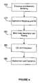
- FIG. 5is a block diagram illustrating an exemplary method of taking the business processes of a company and automating such processes in a robust business software solution that enables the propagation of changes throughout the solution according to an embodiment of the present invention
- FIG. 6is a block diagram illustrating interchangeability of artifacts within two blueprints.
- the present inventionprovides a methodology for developing a comprehensive and robust business software solution.
- the inventionleverages the common ground in what different enterprises seek in a software solution by starting with a basic blueprint of the solution.
- the inventionfurther allows any modifications to the basic blueprint in terms of customizations, development specifics, or deployment details, to be documented in a way that allows the effect of a modification to be seen at all levels of development.
- the relationship between a business process and its implementation in softwareis documented in a systematic way, so at a later date this relationship can be seen, which may motivate the way that future changes to the software or the business processes are addressed.
- This methodologyhelps to maintain accountability of the effect a change to one part of the solution will have on any other part.
- Such software development toolsmay be embodied in the form of program code (i.e., instructions) stored on a computer-readable medium, such as a magnetic, electrical, or optical storage medium, including without limitation a floppy diskette, CD-ROM, CD-RW, DVD-ROM, DVD-RAM, magnetic tape, flash memory, hard disk drive, or any other machine-readable storage medium, wherein, when the program code is loaded into and executed by a machine, such as a computer, the machine becomes an apparatus for practicing the invention.
- program codei.e., instructions
- the present inventionmay also be embodied in the form of program code that is transmitted over some transmission medium, such as over electrical wiring or cabling, through fiber optics, over a network, including the Internet or an intranet, or via any other form of transmission, wherein, when the program code is received and loaded into and executed by a machine, such as a computer, the machine becomes an apparatus for practicing the invention.
- program codeWhen implemented on a general-purpose processor, the program code combines with the processor to provide a unique apparatus that operates analogously to specific logic circuits.
- FIG. 1is a functional diagram showing an overview of an enterprise 100 , and the various levels at which enterprise 100 can be modeled.
- a enterprise as disclosed hereinmay be any type of business organization that is engaged in any line or lines of business.
- the complexity of the business process or processes to be automatedmay range from very simple to highly complex. While a more complex enterprise may require a more complex business software solution, the structure of enterprise 100 is similar regardless of the complexity of the business in which it is engaged.
- enterprise 100can be modeled or defined by a series of levels 110 , 120 , 130 , 140 and 150 .
- the organization 111 of an enterpriseis defined.
- the organizationrepresents such features as how the organization is divided into departments, how the management of the organization is structured, etc. Such a definition can be created in any number of ways, such as by interviewing company personnel, reviewing company organizational references and the like.
- an enterprisemay be defined in terms of each employee's job function.
- an organization 111 of an enterprisemay be defined in terms of each employee's relationship to other employees.
- organization 111may reflect that an airline has a luggage department and a ticketing department, and that the heads of these departments both report to a chief of operations.
- level 120Another level at which an enterprise may be modeled is the process level 120 .
- the relationship between the organization level 110 and the process level 120is that the level 120 represents the various processes that the organizations in level 110 carry out.
- level 110 and level 120convey different types of information. That is, an organization can be described without reference to what it does, and processes can be described without reference to who will perform them.
- there may be a mapping between structures shown at organization level 110 and process level 120that is, certain organizations may participate in certain processes, but not in others. For reasons described below, it may be useful to understand this mapping in order to provide some level of traceability in documenting a software solution.
- level 120shows the various processes that take place in an enterprise.
- the company organization 111 determined at the organization level 110is mapped 113 into a process definition 121 .
- An exemplary process definitionmay be, for example, a process used by an airline to receive a reservation over the Internet.
- Another type of processmay be a process of receiving luggage at a check in counter and transporting it to the appropriate plane.
- an entire companymay be viewed in terms of the processes that take place therein.
- Component level 130shows the various components that will ultimately be used to built a software solution for the enterprise.
- the processes selected for automationare mapped 123 into software components 131 at the component level 130 .
- software components 131may be reused for similar processes and therefore need not be created every time a business software solution is desired. Therefore, a library of business software-specific components 131 may be maintained, and an appropriate component 131 may be selected when needed. Alternatively, if a software component 131 is not available for a particular process definition 121 , then an appropriate component 131 may be created.
- Application level 140shows the applications 141 into which components 131 may be incorporated.
- Software components 131may be incorporated 133 into software applications 141 .
- software applications 141may be already available in a library (not shown) or may be created specifically for the company.
- any combination of pre-fabricated and specially-made components 131 and applications 141may embody a business software solution.
- the business software solutionis enabled 143 by way of a computer infrastructure 151 at the infrastructure level 150 .
- Computer infrastructure 151may be any type of computing equipment that is capable of implementing the business software solution applications 141 as created at the application level 140 .
- the computer infrastructure 151may be any type of computing device that is appropriate to the application 151 being implemented.
- an airline reservation applicationmay be implemented using a networked computer system that is capable of accepting reservation requests from travelers.
- Such a reservation systemmay have communications electronics, such as electronics to enable telephone and computer connections, and may also have a database and computer hardware capable of handling the large number of computations necessary to handle reservations.
- computer infrastructure 151may be handheld electronics or the like for other types of applications 141 .
- an embodimentuses one or more blueprints to define the business process of an enterprise.
- a blueprintis a collection of documents, called artifacts, that can be used to create a cross-referenced representation of the business processes that occur within an enterprise.
- an artifactmay take the form of a word processing document, a spreadsheet, database, organizational chart and the like.
- the content of “artifacts”is more specifically described below in the section entitled “Exemplary Artifacts.”
- an artifactis a type of information relating to a blueprint for a business solution. Typically, several artifacts will be cross-referenced so the interrelationships between business processes may be accounted for.
- a blueprintis preconfigured for a particular industry model.
- one or more blueprintsmay exist for different industries, such as: transportation, banking, insurance, manufacturing and the like.
- the artifacts within the blueprintmay be preconfigured with descriptions of processes that are typical to the industry.
- completing the artifacts and blueprints for a particular enterprisemay simply involve adding unique identification and reference information and descriptions for any unique company processes.
- having preconfigured artifacts and blueprintsmay reduce the time and expense of generating a business software solution for an enterprise.
- a software designer or programmermay use the blueprint as a reference to generate a business software solution as described below in connection with block 230 as well as in FIG. 3 .
- Method 200begins at block 210 , where one or more blueprints that are configured according to an industry model of the company are selected. For example, if the company is an airline, a blueprint that is preconfigured for the airline industry may be used. As may be appreciated, many of the business processes of an enterprise within a particular industry will likely be similar to the business processes of other companies within the industry. Thus, by selecting an appropriate blueprint a time savings in generating a business software solution maybe obtained. In addition, a blueprint may be used in whole or in part, and several blueprints may be employed. For example, an enterprise that has business operations that span two or more industries may require the use of a blueprint from each industry.
- a blueprint from the primary industrymay be employed in conjunction with one or more artifacts from the second industry (e.g., food service).
- artifacts and blueprintsare equally consistent with an embodiment of the present invention.
- the blueprintsare customized according to the specific requirements of the company (block 220 ).
- the companymay employ one or more business processes that are unique in the industry, and therefore the blueprint that was selected in block 210 may not completely describe all of the relevant business processes of the company.
- artifactsmay need to be modified, and even created if necessary.
- any cross-references between artifactsmay need to be changed if the interrelationships between processes require it. Accordingly, at the completion of block 220 a blueprint that describes the relevant business processes of the company, the interrelationships between such processes and the like, is generated.
- a computer programmer or the likemay create, select or modify functional components.
- a functional componentis any type of software component that may be used to implement and/or automate a business process.
- a functional componentmay be a pre-fabricated software module or the like.
- a functional componentmay be used without any modification if the component is capable of automating a business process without any such modifications.
- at least some modification of a componentmay be necessary to both automate a business process and maintain the necessary interrelationships between processes as determined above in connection with block 220 . If necessary, one or more functional components may need to be created to automate a business process. Block 230 is discussed in greater detail in connection with FIG. 3 , below.
- the functional components of block 230 and any additional programmingare incorporated into a business software solution for the company.
- the result of block 240may be a single software application that automates all of the relevant business processes.
- several independent software applicationsmay be generated to automate an enterprise's business processes.
- the present inventionincludes either of these scenarios.
- one or more of the applicationsare in operative communications with each other so as to maintain any operative interrelationships between the applications.
- the software applicationsoperate independently of each other.
- the application program(s)may not implement every business process specified in the blueprint, but may be limited to those processes that are capable of being implemented in software, or for which it is economically feasible or desirable to employ a software-based solution.
- the solutionis implemented or deployed in a hardware infrastructure of the enterprise.
- the hardware selected to implement the solutionis typically hardware that is a suitable platform for the solution within any possible budgetary constraints. If the solution is, for example, a computer program requiring input from an employee who is located at a fixed location, the solution may be implemented by a conventional personal computer or the like. Likewise, if the solution requires input from an employee who will be mobile, then the solution may be implemented using a laptop or handheld computer, or the like. Alternatively, the solution may be implemented using specialized equipment such as, for example, telephone switching equipment, air traffic control equipment, financial databases and the like. As may be appreciated, the above-mentioned hardware may be combined in any manner, and the present invention contemplates any such combination.
- FIG. 3a detail of block 230 from FIG. 2 is shown.
- FIG. 3shows how blueprints (including any customized blueprints that were developed in accordance with block 220 ) may be used to select or design functional components for a business solution.
- the detail of block 230comprises blocks 231 - 235 .
- Block 231is entered from block 220 of FIG. 2 .
- a determinationis made whether the business process documented in an artifact is to be automated. As noted above, some processes are not capable of being automated by software, and still other processes may not be automated for various reasons (e.g., cost) even though such processes are amenable to automation.
- the completed artifactmay nevertheless be retained as a reference (block 232 ).
- the completed artifactmay comprise a word processing document or slide-show presentation that can be used to train new personnel, to assist a programmer in programming related business processes and the like, or develop a software solution in the future as may be permitted by new technology (or changed economic circumstances).
- a functional componentmay be a prefabricated software module or the like. If such a component is available, then such component is used to automate the business process (block 235 ). As may be appreciated, more than one component may be used to automate a business process. In such a situation, the components may be preconfigured to operate together, or may require custom software to operate together to automate the business process. Any such configuration is equally consistent with an embodiment of the present invention. If no components are available, then at block 234 a custom component is written.
- the custom componentmay implement all of the functionality necessary to automate the business process, or only a part of such functionality. In the latter case, the component may be a part of a larger component or software program. Utimately, after either of blocks 234 or 235 , the process exits block 230 and continues to block 240 of FIG. 2 .
- FIG. 4a block diagram is provided that illustrates the types of conventional software development tools that may be utilized at different stages of automating a business process according to an embodiment. As may be appreciated, the following is intended solely as an illustrative list of suitable applications, and any type of business software application is equally consistent with an embodiment of the present invention.
- enterprise and business modelingtakes place to document the business processes of an enterprise as was described above in connection with blocks 210 and 220 in FIG. 2 .
- business modeling softwaresuch as, for example, the PROVISION tool from the Proforma Corporation may be used to generate electronic documents that embody the business processes of the company.
- application modeling and the use of an Integration Development Environment (IDE), such as Logic and Information Network Compiler (LINC) and Unified Modeling Language (UML)takes place in order to design functional software components and/or to create custom software code as was discussed above in connection with block 230 of FIG. 2 .
- IDEIntegration Development Environment
- LINCLogic and Information Network Compiler
- UMLUnified Modeling Language
- RATIONAL ROSEenables a programmer to perform such application modeling.
- ENDEAVOR softwarefrom Unisys Corporation, or the like, may be employed to perform such modeling.
- Business modeling tools and software modeling tools such as those mentioned aboveare generally known in the art and thus are not described herein.
- MDA code generation and testingtakes place to incorporate and test the functional components and/or custom software code that was created as discussed above in connection with block 240 of FIG. 2 .
- MDA code generation and testingmay be performed prior to implementing the solution to perform the company's business processes.
- Such generation and testingmay use software such as, for example, ARCSTYLER from Interactive Objects Software GmbH.
- ARCSTYLERis an architectural IDE for MDA, and enables model-centric design of business infrastructures.
- ENDEAVORfrom the Unisys Corporation or the like.
- IDE and integrationtakes place using, for example, the JUPITER e-business solution from Microsoft Corporation.
- JUPITERis actually a suite of business-specific software applications that enable a programmer, project manager or the like to integrate the components of the business software solution for an enterprise.
- the WEBSPHERE e-business platformfrom IBM Corporation and the WEBLOGIC platform from BEA Systems, Inc. may also be used for block 440 .
- Both WEBSPHERE and WEBLOGICare business software platforms.
- the business software solutionis deployed to the hardware infrastructure and operated using, for example, JUPITER, WEBSPHERE, WEBLOGIC or SENTINEL SERVER from Unisys Corporation.
- an embodiment of the present inventionprovides a solution that will be documented well enough to permit the propagation of changes that may be made to one part of the business software solution to other, related parts of the solution.
- an enterprisemay change a parameter of a particular business process that is automated by a business software solution.
- the softwareis modified to effectuate the change.
- the changemay affect other processes within the company, whether automated or not.
- the completed artifacts that were used to create the now-changed business software solutionprovide the tools for a programmer to determine where additional changes, if any, may need to be made to the rest of the business software solution or artifacts. Accordingly, a programmer will have an efficient way to determine whether a change made to one part of the solution will affect another part of the solution and, if so, where additional changes need to be made.
- Raceabilityin this context, means that any design decisions that are made—including any departures from the original blueprint on which a solution is based—are documented, so that the design decisions, and the effects that they may have on the other parts of the solution, will be known to those who must use or modify the solution in the future.
- this documentationis made at the time that any design decisions—or any actual design of components—is performed, since that is the time at which the understanding of the design, and the implication of any design decisions, will be at its highest.
- traceabilitymay have different meanings for different actors in a business process being modeled by a blueprint.
- the meaningmay also depend on the types of elements (e.g., processes, use cases and the like) that are rendered traceable. In one embodiment of the present invention, seven types of traceability exist, although in other embodiments a lesser or greater number of types may be present.
- traceabilityis “direct associative traceability.” This type of traceability depicts which elements of a given type of model are related to certain elements of another model. For example, in one embodiment, a particular “goal” of a “goal model” is related to a number of system use cases that describe the operational flow of a system that needs to be built or automated. In one embodiment, blueprints have software components or other such mechanisms to associate different elements of a model to other elements defined in other models.
- Transformational traceabilityis, in one embodiment, used to describe automation that enables traceability where model elements of a given model at a particular abstraction level can be automatically traced to model elements at another abstraction level. Transformational traceability is, in some embodiments, the most commonly used definition of the word “traceability.” For example, in one embodiment, a meta-model (i.e., a model that describes another model) is used to delineate the elements of a model that can automatically be traced to elements of another model.
- “Indirect transitive traceability”relates to embodiments in which a relationship between two different elements of different models is not directly explicit.
- direct associative traceabilitya problem that a business is trying to resolve might be tied to strategies that the business uses to resolve such a problem.
- certain test cases that are used to test certain systemscan be directly linked to the business problem the business is trying to resolve. If, in a direct associative manner, a link exists between model element A and model element B, and a link also exists between model element B and another model element C, it will be appreciated that in one embodiment indirect transitive traceability can be used to automatically establish a direct linkage between model elements A and C.
- Model to model traceabilitydeals with transformations between a modeling language such as UML, for example, and another modeling language such as Object Relationship Modeling (ORM).
- ORMObject Relationship Modeling
- a technique used to establish “modeling paradigm”—to—“modeling paradigm” traceabilityis different from a technique used for other types of traceability used in a blueprint framework.
- meta-meta-models, and not meta-models or the actually instantiated models themselvesshould be used to provide such traceability.
- Tool to tool traceabilitypermits the transformation of models between different modeling and development tools. For example, in one embodiment, tool to tool traceability permits interactions between modeling tools of the same company, which ensures upward compatibility. In another embodiment, tool to tool traceability permits interactions between modeling tools provided by different companies, which ensures the preservation of intellectual property in a heterogeneous tool environment.
- “Requirements traceability”relates to the ability to associate business and system requirements to different elements within a full range of models in a blueprint. Significantly, such traceability is unique because it enables associations between non-model artifacts such as natural, unstructured “English” documents and structured models. Blueprints, in one embodiment, incorporate standards such as “Business Requirement Rules” that can be used to quantify and structure non-structured documents so the elements within such documents can be linked to elements of other structured models.
- business process re-engineering traceabilityrelates to linking unstructured business models to other unstructured business models.
- a difference between business process re-engineering traceability and requirements traceabilityis that both the source and the target documents in the present form of traceability are unstructured documents. Therefore, in one embodiment, every traceable element is uniquely dependent upon the business context, so a structured model cannot be used to support automation between such types of un-structured business documents. Even in such a situation, and as noted above, a blueprint according to one embodiment of the present invention may contain reference documentation that enables manual tracing of elements across documents and models.
- an embodiment of the present inventionenables any or all of the above-referenced types of traceability by way of, for example, the organizational structure of one or more blueprints. Implementation details pertaining to the technical aspects of enabling traceability will be apparent to those of skill in the art. Importantly, it will also be appreciated that an embodiment of the present invention provides a means by which any of the above referenced types of traceability may occur by cross-referencing related business processes across artifacts and blueprints.
- FIG. 5a block diagram illustrates a exemplary method of taking the business processes of an enterprise and automating such processes in a robust business software solution that enables the propagation of changes throughout the solution.
- the companycollaborates with a software designer to determine the proper blueprint or blueprints to use.
- a collaborationmay include using a single blueprint in its entirety, or several blueprints.
- Such a collaborationmay also include taking custom-selected artifacts from one or more blueprints and combining such artifacts into a custom blueprint.
- any type of collaboration resulting in any combination of artifacts and blueprintsis equally consistent with an embodiment of the present invention.
- the artifactsare filled out according to the business processes used by the company.
- an artifactmay be pre-configured according to an industry model. Therefore, an artifact may or may not be modified at block 510 , depending on whether the company process adheres to the industry model.
- each process that is documented in an artifactis cross-referenced as applicable to other processes. For example, a process for accepting airline reservations by way of the Internet may be cross-referenced to a process for updating the number of meals to be ordered for a flight based on the number of passenger reservations.
- the completed blueprintis converted into a business software solution.
- the processesare implemented using existing functional components when possible, as indicated by block 525 .
- custom software codeis written to implement such business processes.
- any combination of functional components and custom-written software codeis equally consistent with an embodiment of the present invention.
- various business modeling and software modeling and software modeling toolsmay be used to aid in the software development process.
- the business software solution that was created in block 520is implemented or deployed in an appropriate hardware infrastructure.
- such hardware infrastructuremay be any type of computing device that is capable of executing the business software that is assigned to it.
- many different hardware componentsmay be necessary to implement the entire business software solution.
- Optional blocks 540 , 545 and 550serve to illustrate a process of making a change to a business process that then propagates throughout the business software solution.
- a business processis changed.
- Such a changemay be made to the artifact that documents the business process, or directly to the functional component or software code that automates the business process.
- a programmer or the likefollows the cross-references in the artifact that documents the changed process to determine the artifacts and/or blueprints that are affected by the change and to change such artifacts and/or blueprints accordingly. As was discussed above in connection with FIG.
- the cross-referencesmay simply be text references, or may be something more complex such as an electronic link or the like.
- the functional component or software code associated with the artifacts and/or blueprints changed in block 545is changed according to the change made in block 545 .
- the automated business processundergoes a complete change, whereby the original change is propagated throughout the business software solution. In doing so, an embodiment of the present invention ensures that a change made to one business process is accounted for in all other business processes within an enterprise.
- the changes discussed above in connection with blocks 540 - 550may be made without being implemented in the company's operations.
- an enterprisemay plan to determine the total effect and cost of a particular change to a business process.
- a copy or the like of the business process' artifactmay be made, and the change made according to the plan.
- the cross-references in the artifactare followed to determine whether any other processes are affected by the change.
- the associated artifactsare inspected to determine any additional processes that may be affected, and so on.
- the companywill know the extent to which the desired change will affect the company's business processes, and will be able to accurately estimate the costs involved with making such a change.
- the companymay then decide to implement the change, or may decide to cancel the change, based at least in part on the extent to which the change will affect the company's business processes.
- FIG. 6a block diagram of two blueprints 600 and 605 is illustrated. Within blueprint 600 are artifacts 610 a - g , which are interrelated by way of cross-references 615 .
- blueprint 605contains artifacts 620 a - f —as well as artifact 610 g as will be discussed below—which are interrelated according to cross-references 625 .
- the configuration of blueprints 600 and 605as well as artifacts 610 a - g , 620 a - f and cross-references 615 and 625 , are merely for illustrative purposes, as any configuration is equally consistent with an embodiment of the present invention.
- artifact 610 cis related to both artifact 610 a and artifact 610 a .
- Artifact 610 cis also related to artifacts 610 e - g , but only by way of artifacts 610 a and 610 d .
- Blueprint 605exhibits similar interrelationships between artifacts 620 .
- a financial services companymay employ a process of originating a loan that is similar to an insurance company's process of initiating an insurance application.
- an artifactsuch as artifact 610 g
- an artifactmay be taken from a blueprint, such as blueprint 600 , and copied to a different blueprint 605 .
- artifact 610 ghas been copied and cross-referenced to artifact 620 e to indicate an interrelationship between the business processes described by artifacts 610 g and 620 e .
- Artifact 610 gmay be suitable in its unedited state, or may require modifications. Accordingly, a company, programmer, or the like should only generate a new artifact when the modifications to an existing artifact would be more costly in terms of time or expense.
- a software toolmay present a software designer with a choice of blueprints, and may allow the designer to customize, change, or replace artifacts in the blueprint.
- the toolmay perform the act of propagating any changes in one artifact to any related artifacts.
- a company blueprintis comprised of cross-referenced artifacts.
- the artifactsmay be preconfigured to describe processes that are typical for a given industry model.
- the followingdescribes the types of artifacts that may be associated with a blueprint.
- this set of artifactsis for illustrative purposes only, as an embodiment of the present invention may include any type of artifacts.
- the various artifactsmay be broken down based on the various layers of an enterprise to which a given blueprint applies. These layers include:
- artifactsmay include:
- artifactsmay include:
- artifactsmay include:
- Information generated or used by a systems integration managerincluding:
- artifactsmay include:
- Information generated or used by a deployment architectincluding:
- Information generated or used by a deployment managerincluding:
Landscapes
- Engineering & Computer Science (AREA)
- General Engineering & Computer Science (AREA)
- Theoretical Computer Science (AREA)
- Software Systems (AREA)
- Physics & Mathematics (AREA)
- General Physics & Mathematics (AREA)
- Stored Programmes (AREA)
Abstract
Description
- Parties external to the industry
- Parties internal to the industry
- Industry trends
- Business environment
- Business vision and strategy
- Information needs and business data structures
- Organizational structure
- Business locations
- Business events and results
- Business functions and processes
- Information needs and business data structures
- Organizational structure
- Business locations
- Business operations
- Business workflows and simulations
- Business events and results
- Business rules
- Business class diagrams
- Business vision
- Business glossary
- Business use-case model
- Business use-case spec
- Vision
- Glossary
- Supplementary spec
- Use-case model
- Use-case storyboard
- Use-case specification
- User interface prototype
- Software requirements spec
- Analysis model
- Design model
- Data model
- Software architecture document
- Implementation model
- Test plan
- Integration build plan
- Deployment model
- Deployment plan
- Release notes
- Bill of materials
- Installation artifacts
- End-user support material
- Training materials
Claims (24)
Priority Applications (1)
| Application Number | Priority Date | Filing Date | Title |
|---|---|---|---|
| US10/731,846US7472374B1 (en) | 2003-06-09 | 2003-12-09 | System and method for using blueprints to provide a traceable software solution for an enterprise |
Applications Claiming Priority (2)
| Application Number | Priority Date | Filing Date | Title |
|---|---|---|---|
| US10/457,250US7546575B1 (en) | 2003-06-09 | 2003-06-09 | System and method for using blueprints to provide a software solution for an enterprise |
| US10/731,846US7472374B1 (en) | 2003-06-09 | 2003-12-09 | System and method for using blueprints to provide a traceable software solution for an enterprise |
Related Parent Applications (1)
| Application Number | Title | Priority Date | Filing Date |
|---|---|---|---|
| US10/457,250ContinuationUS7546575B1 (en) | 2003-06-09 | 2003-06-09 | System and method for using blueprints to provide a software solution for an enterprise |
Publications (1)
| Publication Number | Publication Date |
|---|---|
| US7472374B1true US7472374B1 (en) | 2008-12-30 |
Family
ID=40138607
Family Applications (2)
| Application Number | Title | Priority Date | Filing Date |
|---|---|---|---|
| US10/457,250Expired - LifetimeUS7546575B1 (en) | 2003-06-09 | 2003-06-09 | System and method for using blueprints to provide a software solution for an enterprise |
| US10/731,846Expired - Fee RelatedUS7472374B1 (en) | 2003-06-09 | 2003-12-09 | System and method for using blueprints to provide a traceable software solution for an enterprise |
Family Applications Before (1)
| Application Number | Title | Priority Date | Filing Date |
|---|---|---|---|
| US10/457,250Expired - LifetimeUS7546575B1 (en) | 2003-06-09 | 2003-06-09 | System and method for using blueprints to provide a software solution for an enterprise |
Country Status (1)
| Country | Link |
|---|---|
| US (2) | US7546575B1 (en) |
Cited By (50)
| Publication number | Priority date | Publication date | Assignee | Title |
|---|---|---|---|---|
| US20050015743A1 (en)* | 2003-07-17 | 2005-01-20 | Raytheon Company | Designing computer programs |
| US20050138602A1 (en)* | 2003-12-22 | 2005-06-23 | Hinchey Michael G. | System and method for deriving a process-based specification |
| US20060031819A1 (en)* | 2004-08-06 | 2006-02-09 | Microsoft Corporation | Methods and apparatus for creating solutions |
| US20060149582A1 (en)* | 2004-10-18 | 2006-07-06 | Peter Hawkins | Acting on a subject system |
| US20070061354A1 (en)* | 2005-09-12 | 2007-03-15 | Infosys Technologies Ltd. | System for modeling architecture for business systems and methods thereof |
| US20070168921A1 (en)* | 2003-12-19 | 2007-07-19 | Arnaud Bailleul | Method for automatic recovery of uml model requirements and updating thereof |
| US20090048880A1 (en)* | 2007-08-13 | 2009-02-19 | Shoshan Itzhak | Method and system for an enterprise management system |
| US20090119643A1 (en)* | 2007-11-07 | 2009-05-07 | International Business Machines Corporation | Method, system and computer-usable medium for tracking and recording modifications to a software solution |
| US20100235275A1 (en)* | 2009-03-06 | 2010-09-16 | Carl Ansley | Card Processing |
| US20110055802A1 (en)* | 2009-09-03 | 2011-03-03 | Von Unwerth Catherine D | Industry standards modeling systems and methods |
| US20110066566A1 (en)* | 2009-09-16 | 2011-03-17 | International Business Machines Corporation | Conceptual representation of business processes for cross-domain mapping |
| US20110191383A1 (en)* | 2010-02-01 | 2011-08-04 | Oracle International Corporation | Orchestration of business processes using templates |
| US20110218925A1 (en)* | 2010-03-05 | 2011-09-08 | Oracle International Corporation | Change management framework in distributed order orchestration system |
| US20110218926A1 (en)* | 2010-03-05 | 2011-09-08 | Oracle International Corporation | Saving order process state for adjusting long running order management fulfillment processes in a distributed order orchestration system |
| US20110218922A1 (en)* | 2010-03-05 | 2011-09-08 | Oracle International Corporation | Cost of change for adjusting long running order management fulfillment processes for a distributed order orchestration sytem |
| US20110218842A1 (en)* | 2010-03-05 | 2011-09-08 | Oracle International Corporation | Distributed order orchestration system with rules engine |
| US20110218921A1 (en)* | 2010-03-05 | 2011-09-08 | Oracle International Corporation | Notify/inquire fulfillment systems before processing change requests for adjusting long running order management fulfillment processes in a distributed order orchestration system |
| US20110218923A1 (en)* | 2010-03-05 | 2011-09-08 | Oracle International Corporation | Task layer service patterns for adjusting long running order management fulfillment processes for a distributed order orchestration system |
| US20110219218A1 (en)* | 2010-03-05 | 2011-09-08 | Oracle International Corporation | Distributed order orchestration system with rollback checkpoints for adjusting long running order management fulfillment processes |
| US20110218924A1 (en)* | 2010-03-05 | 2011-09-08 | Oracle International Corporation | Distributed order orchestration system for adjusting long running order management fulfillment processes with delta attributes |
| US20110218813A1 (en)* | 2010-03-05 | 2011-09-08 | Oracle International Corporation | Correlating and mapping original orders with new orders for adjusting long running order management fulfillment processes |
| US20110218927A1 (en)* | 2010-03-05 | 2011-09-08 | Oracle International Corporation | Compensation patterns for adjusting long running order management fulfillment processes in an distributed order orchestration system |
| US20110307798A1 (en)* | 2010-06-11 | 2011-12-15 | Microsoft Corporation | Merging Modifications to User Interface Components While Preserving User Customizations |
| US20110321033A1 (en)* | 2010-06-24 | 2011-12-29 | Bmc Software, Inc. | Application Blueprint and Deployment Model for Dynamic Business Service Management (BSM) |
| US8239882B2 (en) | 2005-08-30 | 2012-08-07 | Microsoft Corporation | Markup based extensibility for user interfaces |
| US20130103372A1 (en)* | 2011-10-25 | 2013-04-25 | International Business Machines Corporation | Specifying reusable process models |
| US8762322B2 (en) | 2012-05-22 | 2014-06-24 | Oracle International Corporation | Distributed order orchestration system with extensible flex field support |
| US8799353B2 (en) | 2009-03-30 | 2014-08-05 | Josef Larsson | Scope-based extensibility for control surfaces |
| US20150149983A1 (en)* | 2006-10-20 | 2015-05-28 | International Business Machines Corporation | System and method for automatically determining relationships between software artifacts using multiple evidence sources |
| US20150169322A1 (en)* | 2006-03-31 | 2015-06-18 | Ebay Inc. | Distributed parallel build system |
| US9329976B1 (en)* | 2013-06-24 | 2016-05-03 | Amazon Technologies, Inc. | Application development via a multi-unit device |
| US9588781B2 (en) | 2008-03-31 | 2017-03-07 | Microsoft Technology Licensing, Llc | Associating command surfaces with multiple active components |
| US9658901B2 (en) | 2010-11-12 | 2017-05-23 | Oracle International Corporation | Event-based orchestration in distributed order orchestration system |
| US9672560B2 (en) | 2012-06-28 | 2017-06-06 | Oracle International Corporation | Distributed order orchestration system that transforms sales products to fulfillment products |
| US20170228413A1 (en)* | 2016-02-10 | 2017-08-10 | Tata Consultancy Services Limited | Systems and methods for generating blueprints for enterprises |
| US10248687B2 (en) | 2005-09-12 | 2019-04-02 | Microsoft Technology Licensing, Llc | Expanded search and find user interface |
| US10437431B2 (en) | 2004-08-16 | 2019-10-08 | Microsoft Technology Licensing, Llc | Command user interface for displaying selectable software functionality controls |
| US10482429B2 (en) | 2003-07-01 | 2019-11-19 | Microsoft Technology Licensing, Llc | Automatic grouping of electronic mail |
| US10482637B2 (en) | 2006-06-01 | 2019-11-19 | Microsoft Technology Licensing, Llc | Modifying and formatting a chart using pictorially provided chart elements |
| US10521195B1 (en)* | 2019-03-19 | 2019-12-31 | Servicenow, Inc. | Guided definition of an application programming interface action for a workflow |
| US10521081B2 (en) | 2004-08-16 | 2019-12-31 | Microsoft Technology Licensing, Llc | User interface for displaying a gallery of formatting options |
| US10552769B2 (en) | 2012-01-27 | 2020-02-04 | Oracle International Corporation | Status management framework in a distributed order orchestration system |
| US10592073B2 (en) | 2007-06-29 | 2020-03-17 | Microsoft Technology Licensing, Llc | Exposing non-authoring features through document status information in an out-space user interface |
| US10635266B2 (en) | 2004-08-16 | 2020-04-28 | Microsoft Technology Licensing, Llc | User interface for displaying selectable software functionality controls that are relevant to a selected object |
| US10642927B2 (en) | 2007-06-29 | 2020-05-05 | Microsoft Technology Licensing, Llc | Transitions between user interfaces in a content editing application |
| US10860295B1 (en)* | 2019-01-03 | 2020-12-08 | Amazon Technologies, Inc. | Automated detection of ambiguities in software design diagrams |
| US10997562B2 (en) | 2008-06-20 | 2021-05-04 | Microsoft Technology Licensing, Llc | Synchronized conversation-centric message list and message reading pane |
| US11237802B1 (en) | 2020-07-20 | 2022-02-01 | Bank Of America Corporation | Architecture diagram analysis tool for software development |
| US11397562B2 (en)* | 2019-10-15 | 2022-07-26 | Yingshu Zhou | System and method to generate software development and testing stories utilizing multi-dimensional knowledgebase (MDK) |
| CN114881566A (en)* | 2022-05-20 | 2022-08-09 | 成都飞机工业(集团)有限责任公司 | Installation process information data problem tracing method based on depth-first traversal strategy |
Families Citing this family (72)
| Publication number | Priority date | Publication date | Assignee | Title |
|---|---|---|---|---|
| WO2005122078A2 (en)* | 2004-06-04 | 2005-12-22 | Sap Ag | Consistent set of interfaces derived from a business object model |
| US8370794B2 (en) | 2005-12-30 | 2013-02-05 | Sap Ag | Software model process component |
| US8316344B2 (en) | 2005-12-30 | 2012-11-20 | Sap Ag | Software model deployment units |
| US20080275713A9 (en)* | 2005-12-30 | 2008-11-06 | Shai Alfandary | Architectural design for physical inventory application software |
| US8407664B2 (en)* | 2005-12-30 | 2013-03-26 | Sap Ag | Software model business objects |
| US8326703B2 (en) | 2005-12-30 | 2012-12-04 | Sap Ag | Architectural design for product catalog management application software |
| US8448137B2 (en) | 2005-12-30 | 2013-05-21 | Sap Ag | Software model integration scenarios |
| US8522194B2 (en)* | 2005-12-30 | 2013-08-27 | Sap Ag | Software modeling |
| US8402426B2 (en) | 2005-12-30 | 2013-03-19 | Sap Ag | Architectural design for make to stock application software |
| US8660904B2 (en) | 2005-12-30 | 2014-02-25 | Sap Ag | Architectural design for service request and order management application software |
| US8380553B2 (en) | 2005-12-30 | 2013-02-19 | Sap Ag | Architectural design for plan-driven procurement application software |
| US8321831B2 (en) | 2005-12-30 | 2012-11-27 | Sap Ag | Architectural design for internal projects application software |
| US8396731B2 (en) | 2005-12-30 | 2013-03-12 | Sap Ag | Architectural design for service procurement application software |
| US8327319B2 (en) | 2005-12-30 | 2012-12-04 | Sap Ag | Software model process interaction |
| US8676617B2 (en) | 2005-12-30 | 2014-03-18 | Sap Ag | Architectural design for self-service procurement application software |
| US8396749B2 (en) | 2006-03-30 | 2013-03-12 | Sap Ag | Providing customer relationship management application as enterprise services |
| US8442850B2 (en) | 2006-03-30 | 2013-05-14 | Sap Ag | Providing accounting software application as enterprise services |
| US8396761B2 (en) | 2006-03-30 | 2013-03-12 | Sap Ag | Providing product catalog software application as enterprise services |
| US8538864B2 (en) | 2006-03-30 | 2013-09-17 | Sap Ag | Providing payment software application as enterprise services |
| US8438119B2 (en) | 2006-03-30 | 2013-05-07 | Sap Ag | Foundation layer for services based enterprise software architecture |
| US8326702B2 (en) | 2006-03-30 | 2012-12-04 | Sap Ag | Providing supplier relationship management software application as enterprise services |
| US8321832B2 (en)* | 2006-03-31 | 2012-11-27 | Sap Ag | Composite application modeling |
| US8312416B2 (en) | 2006-04-13 | 2012-11-13 | Sap Ag | Software model business process variant types |
| US20080103862A1 (en)* | 2006-10-27 | 2008-05-01 | International Business Machines Corporation | Instant messaged forms based business process decision point facilitation |
| US8464205B2 (en)* | 2007-04-13 | 2013-06-11 | International Business Machines Corporation | Life cycle of a work packet in a software factory |
| US8327318B2 (en)* | 2007-04-13 | 2012-12-04 | International Business Machines Corporation | Software factory health monitoring |
| US8296719B2 (en)* | 2007-04-13 | 2012-10-23 | International Business Machines Corporation | Software factory readiness review |
| US8359566B2 (en)* | 2007-04-13 | 2013-01-22 | International Business Machines Corporation | Software factory |
| US8566777B2 (en)* | 2007-04-13 | 2013-10-22 | International Business Machines Corporation | Work packet forecasting in a software factory |
| US20080256390A1 (en)* | 2007-04-13 | 2008-10-16 | Chaar Jarir K | Project Induction in a Software Factory |
| US8141040B2 (en)* | 2007-04-13 | 2012-03-20 | International Business Machines Corporation | Assembling work packets within a software factory |
| US8141030B2 (en)* | 2007-08-07 | 2012-03-20 | International Business Machines Corporation | Dynamic routing and load balancing packet distribution with a software factory |
| US8332807B2 (en)* | 2007-08-10 | 2012-12-11 | International Business Machines Corporation | Waste determinants identification and elimination process model within a software factory operating environment |
| US9189757B2 (en) | 2007-08-23 | 2015-11-17 | International Business Machines Corporation | Monitoring and maintaining balance of factory quality attributes within a software factory environment |
| US8539437B2 (en)* | 2007-08-30 | 2013-09-17 | International Business Machines Corporation | Security process model for tasks within a software factory |
| US8510143B2 (en) | 2007-12-31 | 2013-08-13 | Sap Ag | Architectural design for ad-hoc goods movement software |
| US8401936B2 (en) | 2007-12-31 | 2013-03-19 | Sap Ag | Architectural design for expense reimbursement application software |
| US8671034B2 (en) | 2007-12-31 | 2014-03-11 | Sap Ag | Providing human capital management software application as enterprise services |
| US8671033B2 (en) | 2007-12-31 | 2014-03-11 | Sap Ag | Architectural design for personnel events application software |
| US8671032B2 (en) | 2007-12-31 | 2014-03-11 | Sap Ag | Providing payment software application as enterprise services |
| US8315900B2 (en) | 2007-12-31 | 2012-11-20 | Sap Ag | Architectural design for self-service procurement application software |
| US8447657B2 (en) | 2007-12-31 | 2013-05-21 | Sap Ag | Architectural design for service procurement application software |
| US8667469B2 (en) | 2008-05-29 | 2014-03-04 | International Business Machines Corporation | Staged automated validation of work packets inputs and deliverables in a software factory |
| US8595044B2 (en) | 2008-05-29 | 2013-11-26 | International Business Machines Corporation | Determining competence levels of teams working within a software |
| US8452629B2 (en) | 2008-07-15 | 2013-05-28 | International Business Machines Corporation | Work packet enabled active project schedule maintenance |
| US8527329B2 (en) | 2008-07-15 | 2013-09-03 | International Business Machines Corporation | Configuring design centers, assembly lines and job shops of a global delivery network into “on demand” factories |
| US8140367B2 (en)* | 2008-07-22 | 2012-03-20 | International Business Machines Corporation | Open marketplace for distributed service arbitrage with integrated risk management |
| US8375370B2 (en) | 2008-07-23 | 2013-02-12 | International Business Machines Corporation | Application/service event root cause traceability causal and impact analyzer |
| US8418126B2 (en) | 2008-07-23 | 2013-04-09 | International Business Machines Corporation | Software factory semantic reconciliation of data models for work packets |
| US8448129B2 (en) | 2008-07-31 | 2013-05-21 | International Business Machines Corporation | Work packet delegation in a software factory |
| US8336026B2 (en) | 2008-07-31 | 2012-12-18 | International Business Machines Corporation | Supporting a work packet request with a specifically tailored IDE |
| US8271949B2 (en)* | 2008-07-31 | 2012-09-18 | International Business Machines Corporation | Self-healing factory processes in a software factory |
| US8359218B2 (en) | 2008-09-18 | 2013-01-22 | Sap Ag | Computer readable medium for implementing supply chain control using service-oriented methodology |
| US8352338B2 (en) | 2008-09-18 | 2013-01-08 | Sap Ag | Architectural design for time recording application software |
| US8386325B2 (en) | 2008-09-18 | 2013-02-26 | Sap Ag | Architectural design for plan-driven procurement application software |
| US8326706B2 (en) | 2008-09-18 | 2012-12-04 | Sap Ag | Providing logistics execution application as enterprise services |
| US8401928B2 (en) | 2008-09-18 | 2013-03-19 | Sap Ag | Providing supplier relationship management software application as enterprise services |
| US8380549B2 (en) | 2008-09-18 | 2013-02-19 | Sap Ag | Architectural design for embedded support application software |
| US8315926B2 (en) | 2008-09-18 | 2012-11-20 | Sap Ag | Architectural design for tax declaration application software |
| US8374896B2 (en) | 2008-09-18 | 2013-02-12 | Sap Ag | Architectural design for opportunity management application software |
| US8321250B2 (en) | 2008-09-18 | 2012-11-27 | Sap Ag | Architectural design for sell from stock application software |
| US8595077B2 (en) | 2008-09-18 | 2013-11-26 | Sap Ag | Architectural design for service request and order management application software |
| US8818884B2 (en) | 2008-09-18 | 2014-08-26 | Sap Ag | Architectural design for customer returns handling application software |
| US8401908B2 (en) | 2008-12-03 | 2013-03-19 | Sap Ag | Architectural design for make-to-specification application software |
| US8321306B2 (en) | 2008-12-03 | 2012-11-27 | Sap Ag | Architectural design for selling project-based services application software |
| US8321308B2 (en) | 2008-12-03 | 2012-11-27 | Sap Ag | Architectural design for manual invoicing application software |
| US8311904B2 (en) | 2008-12-03 | 2012-11-13 | Sap Ag | Architectural design for intra-company stock transfer application software |
| US8738476B2 (en) | 2008-12-03 | 2014-05-27 | Sap Ag | Architectural design for selling standardized services application software |
| US8671035B2 (en) | 2008-12-11 | 2014-03-11 | Sap Ag | Providing payroll software application as enterprise services |
| US8407073B2 (en) | 2010-08-25 | 2013-03-26 | International Business Machines Corporation | Scheduling resources from a multi-skill multi-level human resource pool |
| US8660878B2 (en) | 2011-06-15 | 2014-02-25 | International Business Machines Corporation | Model-driven assignment of work to a software factory |
| US10936305B2 (en)* | 2017-11-13 | 2021-03-02 | Sap Se | Configuration guide editor to generate interactive configuration guides and automation content |
Citations (3)
| Publication number | Priority date | Publication date | Assignee | Title |
|---|---|---|---|---|
| US5987247A (en)* | 1997-05-09 | 1999-11-16 | International Business Machines Corporation | Systems, methods and computer program products for building frameworks in an object oriented environment |
| US6223343B1 (en)* | 1997-04-04 | 2001-04-24 | State Farm Mutual Automobile Insurance Co. | Computer system and method to track and control element changes throughout application development |
| US20020091990A1 (en)* | 2000-10-04 | 2002-07-11 | Todd Little | System for software application development and modeling |
Family Cites Families (3)
| Publication number | Priority date | Publication date | Assignee | Title |
|---|---|---|---|---|
| US6539374B2 (en)* | 1999-06-03 | 2003-03-25 | Microsoft Corporation | Methods, apparatus and data structures for providing a uniform representation of various types of information |
| CA2440031C (en)* | 2001-02-22 | 2013-07-02 | Accenture Global Services Gmbh | Distributed development environment for building internet applications by developers at remote locations |
| US20040054985A1 (en)* | 2002-06-25 | 2004-03-18 | Sewell Marc T. Burton | Tool and notation for capturing and communicating enterprise and technology structures, processes, strategies, and concepts |
- 2003
- 2003-06-09USUS10/457,250patent/US7546575B1/ennot_activeExpired - Lifetime
- 2003-12-09USUS10/731,846patent/US7472374B1/ennot_activeExpired - Fee Related
Patent Citations (3)
| Publication number | Priority date | Publication date | Assignee | Title |
|---|---|---|---|---|
| US6223343B1 (en)* | 1997-04-04 | 2001-04-24 | State Farm Mutual Automobile Insurance Co. | Computer system and method to track and control element changes throughout application development |
| US5987247A (en)* | 1997-05-09 | 1999-11-16 | International Business Machines Corporation | Systems, methods and computer program products for building frameworks in an object oriented environment |
| US20020091990A1 (en)* | 2000-10-04 | 2002-07-11 | Todd Little | System for software application development and modeling |
Cited By (76)
| Publication number | Priority date | Publication date | Assignee | Title |
|---|---|---|---|---|
| US10482429B2 (en) | 2003-07-01 | 2019-11-19 | Microsoft Technology Licensing, Llc | Automatic grouping of electronic mail |
| US20050015743A1 (en)* | 2003-07-17 | 2005-01-20 | Raytheon Company | Designing computer programs |
| US8219968B2 (en)* | 2003-07-17 | 2012-07-10 | Raytheon Company | Designing computer programs |
| US20070168921A1 (en)* | 2003-12-19 | 2007-07-19 | Arnaud Bailleul | Method for automatic recovery of uml model requirements and updating thereof |
| US7543274B2 (en)* | 2003-12-22 | 2009-06-02 | The United States Of America As Represented By The Administrator Of The National Aeronautics And Space Administration | System and method for deriving a process-based specification |
| US20050138602A1 (en)* | 2003-12-22 | 2005-06-23 | Hinchey Michael G. | System and method for deriving a process-based specification |
| US20060031819A1 (en)* | 2004-08-06 | 2006-02-09 | Microsoft Corporation | Methods and apparatus for creating solutions |
| US10437431B2 (en) | 2004-08-16 | 2019-10-08 | Microsoft Technology Licensing, Llc | Command user interface for displaying selectable software functionality controls |
| US10521081B2 (en) | 2004-08-16 | 2019-12-31 | Microsoft Technology Licensing, Llc | User interface for displaying a gallery of formatting options |
| US10635266B2 (en) | 2004-08-16 | 2020-04-28 | Microsoft Technology Licensing, Llc | User interface for displaying selectable software functionality controls that are relevant to a selected object |
| US7822592B2 (en)* | 2004-10-18 | 2010-10-26 | Manthatron-Ip Limited | Acting on a subject system |
| US20060149582A1 (en)* | 2004-10-18 | 2006-07-06 | Peter Hawkins | Acting on a subject system |
| US8239882B2 (en) | 2005-08-30 | 2012-08-07 | Microsoft Corporation | Markup based extensibility for user interfaces |
| US10248687B2 (en) | 2005-09-12 | 2019-04-02 | Microsoft Technology Licensing, Llc | Expanded search and find user interface |
| US7716254B2 (en)* | 2005-09-12 | 2010-05-11 | Infosys Technologies Ltd. | System for modeling architecture for business systems and methods thereof |
| US20070061354A1 (en)* | 2005-09-12 | 2007-03-15 | Infosys Technologies Ltd. | System for modeling architecture for business systems and methods thereof |
| US11106459B2 (en) | 2006-03-31 | 2021-08-31 | Ebay Inc. | Distributed parallel build system |
| US10048961B2 (en) | 2006-03-31 | 2018-08-14 | Ebay Inc. | Distributed parallel build system |
| US9529589B2 (en)* | 2006-03-31 | 2016-12-27 | Ebay Inc. | Distributed parallel build system |
| US20150169322A1 (en)* | 2006-03-31 | 2015-06-18 | Ebay Inc. | Distributed parallel build system |
| US10620943B2 (en) | 2006-03-31 | 2020-04-14 | Ebay Inc. | Distributed parallel build system |
| US10482637B2 (en) | 2006-06-01 | 2019-11-19 | Microsoft Technology Licensing, Llc | Modifying and formatting a chart using pictorially provided chart elements |
| US20150149983A1 (en)* | 2006-10-20 | 2015-05-28 | International Business Machines Corporation | System and method for automatically determining relationships between software artifacts using multiple evidence sources |
| US9430591B2 (en)* | 2006-10-20 | 2016-08-30 | International Business Machines Corporation | System and method for automatically determining relationships between software artifacts using multiple evidence sources |
| US10642927B2 (en) | 2007-06-29 | 2020-05-05 | Microsoft Technology Licensing, Llc | Transitions between user interfaces in a content editing application |
| US10592073B2 (en) | 2007-06-29 | 2020-03-17 | Microsoft Technology Licensing, Llc | Exposing non-authoring features through document status information in an out-space user interface |
| US20090048880A1 (en)* | 2007-08-13 | 2009-02-19 | Shoshan Itzhak | Method and system for an enterprise management system |
| US8418138B2 (en)* | 2007-11-07 | 2013-04-09 | International Business Machines Corporation | Method, system and computer-usable medium for tracking and recording modifications to a software solution |
| US20090119643A1 (en)* | 2007-11-07 | 2009-05-07 | International Business Machines Corporation | Method, system and computer-usable medium for tracking and recording modifications to a software solution |
| US10445114B2 (en) | 2008-03-31 | 2019-10-15 | Microsoft Technology Licensing, Llc | Associating command surfaces with multiple active components |
| US9588781B2 (en) | 2008-03-31 | 2017-03-07 | Microsoft Technology Licensing, Llc | Associating command surfaces with multiple active components |
| US10997562B2 (en) | 2008-06-20 | 2021-05-04 | Microsoft Technology Licensing, Llc | Synchronized conversation-centric message list and message reading pane |
| US20100235275A1 (en)* | 2009-03-06 | 2010-09-16 | Carl Ansley | Card Processing |
| US8799353B2 (en) | 2009-03-30 | 2014-08-05 | Josef Larsson | Scope-based extensibility for control surfaces |
| US20110055802A1 (en)* | 2009-09-03 | 2011-03-03 | Von Unwerth Catherine D | Industry standards modeling systems and methods |
| US11315208B2 (en) | 2009-09-16 | 2022-04-26 | International Business Machines Corporation | Conceptual representation of business processes for cross-domain mapping |
| US20110066566A1 (en)* | 2009-09-16 | 2011-03-17 | International Business Machines Corporation | Conceptual representation of business processes for cross-domain mapping |
| US8402064B2 (en) | 2010-02-01 | 2013-03-19 | Oracle International Corporation | Orchestration of business processes using templates |
| US20110191383A1 (en)* | 2010-02-01 | 2011-08-04 | Oracle International Corporation | Orchestration of business processes using templates |
| US20110218923A1 (en)* | 2010-03-05 | 2011-09-08 | Oracle International Corporation | Task layer service patterns for adjusting long running order management fulfillment processes for a distributed order orchestration system |
| US8793262B2 (en) | 2010-03-05 | 2014-07-29 | Oracle International Corporation | Correlating and mapping original orders with new orders for adjusting long running order management fulfillment processes |
| US9269075B2 (en) | 2010-03-05 | 2016-02-23 | Oracle International Corporation | Distributed order orchestration system for adjusting long running order management fulfillment processes with delta attributes |
| US20110218842A1 (en)* | 2010-03-05 | 2011-09-08 | Oracle International Corporation | Distributed order orchestration system with rules engine |
| US20110218921A1 (en)* | 2010-03-05 | 2011-09-08 | Oracle International Corporation | Notify/inquire fulfillment systems before processing change requests for adjusting long running order management fulfillment processes in a distributed order orchestration system |
| US20110218927A1 (en)* | 2010-03-05 | 2011-09-08 | Oracle International Corporation | Compensation patterns for adjusting long running order management fulfillment processes in an distributed order orchestration system |
| US10789562B2 (en) | 2010-03-05 | 2020-09-29 | Oracle International Corporation | Compensation patterns for adjusting long running order management fulfillment processes in an distributed order orchestration system |
| US20110218924A1 (en)* | 2010-03-05 | 2011-09-08 | Oracle International Corporation | Distributed order orchestration system for adjusting long running order management fulfillment processes with delta attributes |
| US20110219218A1 (en)* | 2010-03-05 | 2011-09-08 | Oracle International Corporation | Distributed order orchestration system with rollback checkpoints for adjusting long running order management fulfillment processes |
| US20110218813A1 (en)* | 2010-03-05 | 2011-09-08 | Oracle International Corporation | Correlating and mapping original orders with new orders for adjusting long running order management fulfillment processes |
| US9904898B2 (en) | 2010-03-05 | 2018-02-27 | Oracle International Corporation | Distributed order orchestration system with rules engine |
| US20110218922A1 (en)* | 2010-03-05 | 2011-09-08 | Oracle International Corporation | Cost of change for adjusting long running order management fulfillment processes for a distributed order orchestration sytem |
| US10061464B2 (en) | 2010-03-05 | 2018-08-28 | Oracle International Corporation | Distributed order orchestration system with rollback checkpoints for adjusting long running order management fulfillment processes |
| US20110218926A1 (en)* | 2010-03-05 | 2011-09-08 | Oracle International Corporation | Saving order process state for adjusting long running order management fulfillment processes in a distributed order orchestration system |
| US10395205B2 (en)* | 2010-03-05 | 2019-08-27 | Oracle International Corporation | Cost of change for adjusting long running order management fulfillment processes for a distributed order orchestration system |
| US20110218925A1 (en)* | 2010-03-05 | 2011-09-08 | Oracle International Corporation | Change management framework in distributed order orchestration system |
| US8302014B2 (en)* | 2010-06-11 | 2012-10-30 | Microsoft Corporation | Merging modifications to user interface components while preserving user customizations |
| US20110307798A1 (en)* | 2010-06-11 | 2011-12-15 | Microsoft Corporation | Merging Modifications to User Interface Components While Preserving User Customizations |
| US20110321033A1 (en)* | 2010-06-24 | 2011-12-29 | Bmc Software, Inc. | Application Blueprint and Deployment Model for Dynamic Business Service Management (BSM) |
| US9805322B2 (en)* | 2010-06-24 | 2017-10-31 | Bmc Software, Inc. | Application blueprint and deployment model for dynamic business service management (BSM) |
| US9658901B2 (en) | 2010-11-12 | 2017-05-23 | Oracle International Corporation | Event-based orchestration in distributed order orchestration system |
| US8938714B2 (en)* | 2011-10-25 | 2015-01-20 | International Business Machines Corporation | Specifying reusable process models |
| US20130103372A1 (en)* | 2011-10-25 | 2013-04-25 | International Business Machines Corporation | Specifying reusable process models |
| US10552769B2 (en) | 2012-01-27 | 2020-02-04 | Oracle International Corporation | Status management framework in a distributed order orchestration system |
| US8762322B2 (en) | 2012-05-22 | 2014-06-24 | Oracle International Corporation | Distributed order orchestration system with extensible flex field support |
| US9672560B2 (en) | 2012-06-28 | 2017-06-06 | Oracle International Corporation | Distributed order orchestration system that transforms sales products to fulfillment products |
| US9785539B2 (en) | 2013-06-24 | 2017-10-10 | Amazon Technologies, Inc. | Application development via a multi-unit device |
| US9329976B1 (en)* | 2013-06-24 | 2016-05-03 | Amazon Technologies, Inc. | Application development via a multi-unit device |
| US20170228413A1 (en)* | 2016-02-10 | 2017-08-10 | Tata Consultancy Services Limited | Systems and methods for generating blueprints for enterprises |
| US10474665B2 (en)* | 2016-02-10 | 2019-11-12 | Tata Consultancy Services Limited | Systems and methods for generating blueprints for enterprises |
| US10860295B1 (en)* | 2019-01-03 | 2020-12-08 | Amazon Technologies, Inc. | Automated detection of ambiguities in software design diagrams |
| US10521195B1 (en)* | 2019-03-19 | 2019-12-31 | Servicenow, Inc. | Guided definition of an application programming interface action for a workflow |
| US11068241B2 (en) | 2019-03-19 | 2021-07-20 | Servicenow, Inc. | Guided definition of an application programming interface action for a workflow |
| US11397562B2 (en)* | 2019-10-15 | 2022-07-26 | Yingshu Zhou | System and method to generate software development and testing stories utilizing multi-dimensional knowledgebase (MDK) |
| US11237802B1 (en) | 2020-07-20 | 2022-02-01 | Bank Of America Corporation | Architecture diagram analysis tool for software development |
| CN114881566A (en)* | 2022-05-20 | 2022-08-09 | 成都飞机工业(集团)有限责任公司 | Installation process information data problem tracing method based on depth-first traversal strategy |
| CN114881566B (en)* | 2022-05-20 | 2024-06-04 | 成都飞机工业(集团)有限责任公司 | Installation process information data problem tracing method based on depth-first traversal strategy |
Also Published As
| Publication number | Publication date |
|---|---|
| US7546575B1 (en) | 2009-06-09 |
Similar Documents
| Publication | Publication Date | Title |
|---|---|---|
| US7472374B1 (en) | System and method for using blueprints to provide a traceable software solution for an enterprise | |
| Mohapatra et al. | Fundamentals of software engineering | |
| Fairley | Managing and leading software projects | |
| Kroll et al. | The rational unified process made easy: a practitioner's guide to the RUP | |
| US8332807B2 (en) | Waste determinants identification and elimination process model within a software factory operating environment | |
| US8234621B2 (en) | Rule based instantiation of software- and system development processes | |
| US20050021348A1 (en) | Business solution management (BSM) | |
| US20090271760A1 (en) | Method for application development | |
| Snoeck et al. | Agile MERODE: a model-driven software engineering method for user-centric and value-based development | |
| Ambler | A manager’s introduction to the Rational Unified Process (RUP) | |
| Hause | The Unified Profile for DoDAF/MODAF (UPDM) enabling systems of systems on many levels | |
| Tegarden et al. | Systems Analysis and Design, with EEPUB Access: An Object-Oriented Approach with UML | |
| Apperly | Service-and component-based development using Select Perspective and UML | |
| Land et al. | Practical support for lean six sigma software process definition: using IEEE software engineering standards | |
| Hull et al. | Software development processes—an assessment | |
| Derakhshanmanesh et al. | Model-integrating development of software systems: a flexible component-based approach | |
| Péraire et al. | The IBM Rational Unified Process for System z | |
| Beedle | Pattern based reengineering | |
| Crookshanks | Practical enterprise software development techniques: Tools and techniques for large scale solutions | |
| Howard | IT release management: A hands-on guide | |
| Van Gorp et al. | Cavit: a consistency maintenance framework based on transformation contracts | |
| Vidales12 et al. | A new MDA approach based on BPM and SOA to improve software development process | |
| van de Weerd | Advancing in software product management: An incremental method engineering approach | |
| Eide | Quantification and traceability of requirements | |
| Hitesh | Fundamentals of Software Engineering |
Legal Events
| Date | Code | Title | Description |
|---|---|---|---|
| AS | Assignment | Owner name:CITIBANK, N.A.,NEW YORK Free format text:SECURITY AGREEMENT;ASSIGNORS:UNISYS CORPORATION;UNISYS HOLDING CORPORATION;REEL/FRAME:018003/0001 Effective date:20060531 Owner name:CITIBANK, N.A., NEW YORK Free format text:SECURITY AGREEMENT;ASSIGNORS:UNISYS CORPORATION;UNISYS HOLDING CORPORATION;REEL/FRAME:018003/0001 Effective date:20060531 | |
| AS | Assignment | Owner name:UNISYS CORPORATION, PENNSYLVANIA Free format text:RELEASE BY SECURED PARTY;ASSIGNOR:CITIBANK, N.A.;REEL/FRAME:023312/0044 Effective date:20090601 Owner name:UNISYS HOLDING CORPORATION, DELAWARE Free format text:RELEASE BY SECURED PARTY;ASSIGNOR:CITIBANK, N.A.;REEL/FRAME:023312/0044 Effective date:20090601 Owner name:UNISYS CORPORATION,PENNSYLVANIA Free format text:RELEASE BY SECURED PARTY;ASSIGNOR:CITIBANK, N.A.;REEL/FRAME:023312/0044 Effective date:20090601 Owner name:UNISYS HOLDING CORPORATION,DELAWARE Free format text:RELEASE BY SECURED PARTY;ASSIGNOR:CITIBANK, N.A.;REEL/FRAME:023312/0044 Effective date:20090601 | |
| AS | Assignment | Owner name:UNISYS CORPORATION, PENNSYLVANIA Free format text:RELEASE BY SECURED PARTY;ASSIGNOR:CITIBANK, N.A.;REEL/FRAME:023263/0631 Effective date:20090601 Owner name:UNISYS HOLDING CORPORATION, DELAWARE Free format text:RELEASE BY SECURED PARTY;ASSIGNOR:CITIBANK, N.A.;REEL/FRAME:023263/0631 Effective date:20090601 Owner name:UNISYS CORPORATION,PENNSYLVANIA Free format text:RELEASE BY SECURED PARTY;ASSIGNOR:CITIBANK, N.A.;REEL/FRAME:023263/0631 Effective date:20090601 Owner name:UNISYS HOLDING CORPORATION,DELAWARE Free format text:RELEASE BY SECURED PARTY;ASSIGNOR:CITIBANK, N.A.;REEL/FRAME:023263/0631 Effective date:20090601 | |
| AS | Assignment | Owner name:DEUTSCHE BANK TRUST COMPANY AMERICAS, AS COLLATERA Free format text:PATENT SECURITY AGREEMENT (PRIORITY LIEN);ASSIGNOR:UNISYS CORPORATION;REEL/FRAME:023355/0001 Effective date:20090731 | |
| AS | Assignment | Owner name:DEUTSCHE BANK TRUST COMPANY AMERICAS, AS COLLATERA Free format text:PATENT SECURITY AGREEMENT (JUNIOR LIEN);ASSIGNOR:UNISYS CORPORATION;REEL/FRAME:023364/0098 Effective date:20090731 | |
| AS | Assignment | Owner name:GENERAL ELECTRIC CAPITAL CORPORATION, AS AGENT, IL Free format text:SECURITY AGREEMENT;ASSIGNOR:UNISYS CORPORATION;REEL/FRAME:026509/0001 Effective date:20110623 | |
| FPAY | Fee payment | Year of fee payment:4 | |
| AS | Assignment | Owner name:UNISYS CORPORATION, PENNSYLVANIA Free format text:RELEASE BY SECURED PARTY;ASSIGNOR:DEUTSCHE BANK TRUST COMPANY;REEL/FRAME:030004/0619 Effective date:20121127 | |
| AS | Assignment | Owner name:UNISYS CORPORATION, PENNSYLVANIA Free format text:RELEASE BY SECURED PARTY;ASSIGNOR:DEUTSCHE BANK TRUST COMPANY AMERICAS, AS COLLATERAL TRUSTEE;REEL/FRAME:030082/0545 Effective date:20121127 | |
| REMI | Maintenance fee reminder mailed | ||
| LAPS | Lapse for failure to pay maintenance fees | ||
| STCH | Information on status: patent discontinuation | Free format text:PATENT EXPIRED DUE TO NONPAYMENT OF MAINTENANCE FEES UNDER 37 CFR 1.362 | |
| FP | Expired due to failure to pay maintenance fee | Effective date:20161230 | |
| AS | Assignment | Owner name:UNISYS CORPORATION, PENNSYLVANIA Free format text:RELEASE BY SECURED PARTY;ASSIGNOR:WELLS FARGO BANK, NATIONAL ASSOCIATION (SUCCESSOR TO GENERAL ELECTRIC CAPITAL CORPORATION);REEL/FRAME:044416/0358 Effective date:20171005 |