US7472231B1 - Storage area network data cache - Google Patents
Storage area network data cacheDownload PDFInfo
- Publication number
- US7472231B1 US7472231B1US10/237,560US23756002AUS7472231B1US 7472231 B1US7472231 B1US 7472231B1US 23756002 AUS23756002 AUS 23756002AUS 7472231 B1US7472231 B1US 7472231B1
- Authority
- US
- United States
- Prior art keywords
- data
- cache
- segment
- block
- storage
- Prior art date
- Legal status (The legal status is an assumption and is not a legal conclusion. Google has not performed a legal analysis and makes no representation as to the accuracy of the status listed.)
- Expired - Lifetime, expires
Links
Images


Classifications
- G—PHYSICS
- G06—COMPUTING OR CALCULATING; COUNTING
- G06F—ELECTRIC DIGITAL DATA PROCESSING
- G06F3/00—Input arrangements for transferring data to be processed into a form capable of being handled by the computer; Output arrangements for transferring data from processing unit to output unit, e.g. interface arrangements
- G06F3/06—Digital input from, or digital output to, record carriers, e.g. RAID, emulated record carriers or networked record carriers
- G06F3/0601—Interfaces specially adapted for storage systems
- G06F3/0602—Interfaces specially adapted for storage systems specifically adapted to achieve a particular effect
- G06F3/061—Improving I/O performance
- G06F3/0613—Improving I/O performance in relation to throughput
- G—PHYSICS
- G06—COMPUTING OR CALCULATING; COUNTING
- G06F—ELECTRIC DIGITAL DATA PROCESSING
- G06F12/00—Accessing, addressing or allocating within memory systems or architectures
- G06F12/02—Addressing or allocation; Relocation
- G06F12/08—Addressing or allocation; Relocation in hierarchically structured memory systems, e.g. virtual memory systems
- G06F12/0802—Addressing of a memory level in which the access to the desired data or data block requires associative addressing means, e.g. caches
- G06F12/0804—Addressing of a memory level in which the access to the desired data or data block requires associative addressing means, e.g. caches with main memory updating
- G—PHYSICS
- G06—COMPUTING OR CALCULATING; COUNTING
- G06F—ELECTRIC DIGITAL DATA PROCESSING
- G06F12/00—Accessing, addressing or allocating within memory systems or architectures
- G06F12/02—Addressing or allocation; Relocation
- G06F12/08—Addressing or allocation; Relocation in hierarchically structured memory systems, e.g. virtual memory systems
- G06F12/0802—Addressing of a memory level in which the access to the desired data or data block requires associative addressing means, e.g. caches
- G06F12/0806—Multiuser, multiprocessor or multiprocessing cache systems
- G06F12/0813—Multiuser, multiprocessor or multiprocessing cache systems with a network or matrix configuration
- G—PHYSICS
- G06—COMPUTING OR CALCULATING; COUNTING
- G06F—ELECTRIC DIGITAL DATA PROCESSING
- G06F12/00—Accessing, addressing or allocating within memory systems or architectures
- G06F12/02—Addressing or allocation; Relocation
- G06F12/08—Addressing or allocation; Relocation in hierarchically structured memory systems, e.g. virtual memory systems
- G06F12/0802—Addressing of a memory level in which the access to the desired data or data block requires associative addressing means, e.g. caches
- G06F12/0862—Addressing of a memory level in which the access to the desired data or data block requires associative addressing means, e.g. caches with prefetch
- G—PHYSICS
- G06—COMPUTING OR CALCULATING; COUNTING
- G06F—ELECTRIC DIGITAL DATA PROCESSING
- G06F12/00—Accessing, addressing or allocating within memory systems or architectures
- G06F12/02—Addressing or allocation; Relocation
- G06F12/08—Addressing or allocation; Relocation in hierarchically structured memory systems, e.g. virtual memory systems
- G06F12/0802—Addressing of a memory level in which the access to the desired data or data block requires associative addressing means, e.g. caches
- G06F12/0866—Addressing of a memory level in which the access to the desired data or data block requires associative addressing means, e.g. caches for peripheral storage systems, e.g. disk cache
- G—PHYSICS
- G06—COMPUTING OR CALCULATING; COUNTING
- G06F—ELECTRIC DIGITAL DATA PROCESSING
- G06F12/00—Accessing, addressing or allocating within memory systems or architectures
- G06F12/02—Addressing or allocation; Relocation
- G06F12/08—Addressing or allocation; Relocation in hierarchically structured memory systems, e.g. virtual memory systems
- G06F12/10—Address translation
- G06F12/1081—Address translation for peripheral access to main memory, e.g. direct memory access [DMA]
- G—PHYSICS
- G06—COMPUTING OR CALCULATING; COUNTING
- G06F—ELECTRIC DIGITAL DATA PROCESSING
- G06F12/00—Accessing, addressing or allocating within memory systems or architectures
- G06F12/02—Addressing or allocation; Relocation
- G06F12/08—Addressing or allocation; Relocation in hierarchically structured memory systems, e.g. virtual memory systems
- G06F12/12—Replacement control
- G06F12/121—Replacement control using replacement algorithms
- G06F12/126—Replacement control using replacement algorithms with special data handling, e.g. priority of data or instructions, handling errors or pinning
- G—PHYSICS
- G06—COMPUTING OR CALCULATING; COUNTING
- G06F—ELECTRIC DIGITAL DATA PROCESSING
- G06F3/00—Input arrangements for transferring data to be processed into a form capable of being handled by the computer; Output arrangements for transferring data from processing unit to output unit, e.g. interface arrangements
- G06F3/06—Digital input from, or digital output to, record carriers, e.g. RAID, emulated record carriers or networked record carriers
- G06F3/0601—Interfaces specially adapted for storage systems
- G06F3/0628—Interfaces specially adapted for storage systems making use of a particular technique
- G06F3/0655—Vertical data movement, i.e. input-output transfer; data movement between one or more hosts and one or more storage devices
- G—PHYSICS
- G06—COMPUTING OR CALCULATING; COUNTING
- G06F—ELECTRIC DIGITAL DATA PROCESSING
- G06F3/00—Input arrangements for transferring data to be processed into a form capable of being handled by the computer; Output arrangements for transferring data from processing unit to output unit, e.g. interface arrangements
- G06F3/06—Digital input from, or digital output to, record carriers, e.g. RAID, emulated record carriers or networked record carriers
- G06F3/0601—Interfaces specially adapted for storage systems
- G06F3/0668—Interfaces specially adapted for storage systems adopting a particular infrastructure
- G06F3/0671—In-line storage system
- G06F3/0673—Single storage device
- G—PHYSICS
- G06—COMPUTING OR CALCULATING; COUNTING
- G06F—ELECTRIC DIGITAL DATA PROCESSING
- G06F2212/00—Indexing scheme relating to accessing, addressing or allocation within memory systems or architectures
- G06F2212/26—Using a specific storage system architecture
- G06F2212/263—Network storage, e.g. SAN or NAS
Definitions
- the present inventionrelates to data caches for storage area networks (SAN).
- SANstorage area networks
- a microprocessortypically will have at least a first level cache on the microprocessor chip itself, and may be connected to a separate SDRAM cache which is a second-level cache.
- a storage controllertypically will have a cache.
- the same cache structuretypically is used, with the cache being attached to the storage controller which is then connected to the network. Thus, caching is done at the endpoint of the data transmission over the network.
- a virtualization engineis interposed between the host and multiple physical storage controllers.
- the hostcan send data requests to the virtualization engine, which then determines which storage controller to send it to, and forwards the data over the network to the storage controller.
- the storage controllerthen uses its own associated cache in connection with data accesses.
- the present inventionprovides a cache connected to the virtualization engine in the center of a storage area network.
- the inventioncaches data in a virtual cache, without requiring translation to the physical location.
- the cachingis done as the data crosses the network through the virtualization engine, eliminating the need to do the further translation and forwarding over the network to the actual storage controller in the event the data is in the cache.
- the inventioneliminates the need for multiple caches at each physical storage controller.
- the cache of the present inventionis segmented.
- a first look-up tablepreferably a content addressable memory (CAM) compares a virtual logic unit number (VLUN) assigned to the host and a logical block address of the data being sought to determine if the segment is in the cache. If there is a hit, a second look-up table (e.g., a SDRAM) is used to determine if the logical block is stored in the data cache.
- VLUNvirtual logic unit number
- SDRAMSecure Digital Random Access Memory
- the virtualization engineexamines a tag in the frame to determine if the data is cacheable, with only cacheable data being sent to the data cache, further improving the speed.
- VLUNsare marked as cacheable or non-cacheable by the operator as they are configured in the system. When accessing data in a cacheable VLUN the host may mark the transaction as non-cacheable.
- the data cacheuses a network processor, since the cache is located in the middle of the network, and thus network processing capabilities are required, unlike typical storage controller caches.
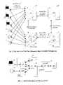
- FIG. 1is a block diagram of a SAN system incorporating a data cache according to an embodiment of the present invention.
- FIG. 2is a block diagram of the VSX Data Cache Module of FIG. 1 .
- FIG. 3is a block diagram of a Logical VSX with VDC In A Simple Storage Area Network according to an embodiment of the invention.
- FIG. 4is a block diagram of a Single Box VSX with Cache (VSX/C) according to an embodiment of the invention.
- FIG. 5is a block diagram of a VSX with VSX/C In Fibre Channel & High Available Configuration, illustrating fibre channel connections, according to an embodiment of the invention.
- FIG. 6is a block diagram illustrating a logical interconnect of VSX and VSX/C according to an embodiment of the invention.
- FIG. 7is a block diagram of a Detailed VSX Data Cache (VDC) Module according to an embodiment of the invention.
- FIG. 8is a block diagram of a Data Cache Engine (DCE) according to an embodiment of the invention.
- DCEData Cache Engine
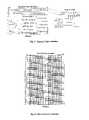
- FIG. 9is a diagram illustrating the segment mapping to data blocks according to an embodiment of the invention.
- FIG. 10is a diagram of an embodiment of CAM data entries.
- FIG. 11is a diagram of an embodiment of the segment data structure.
- FIG. 12is a diagram of an embodiment of a block pointer structure.
- FIG. 13is a diagram illustrating a look-up operation according to an embodiment of the invention.
- FIG. 14is a diagram illustrating a segment aging operation according to an embodiment of the invention.
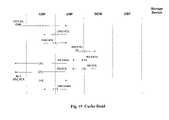
- FIG. 15is a diagram illustrating a cache read according to an embodiment of the invention.
- FIG. 16is a diagram of an internal cache read according to an embodiment of the invention.
- FIG. 17is a diagram of a cache memory with partial data according to an embodiment of the invention.
- FIG. 18is a diagram illustrating a cache read with a partial miss according to an embodiment of the invention.
- FIG. 19is a diagram of an internal cache read with a partial miss according to an embodiment of the invention.
- FIG. 20is a diagram of a successful cache write according to an embodiment of the invention.
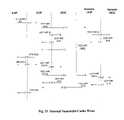
- FIG. 21is a diagram of an internal successful cache write according to an embodiment of the invention.
- FIG. 22is a diagram of a cache write through according to an embodiment of the invention.
- the SAN Data Cache of the present inventionaddresses problems that are created in large SAN installations by providing a SAN-centric resource that increases overall SAN performance and facilitates data and storage resource management.
- the SAN Data Cachesolves and/or provides for the following:
- the SAN Data Cachewill be described in the context as it relates to the Confluence Networks Virtual Storage Exchange (VSX) platform and be called the VSX Data Cache.
- VSXConfluence Networks Virtual Storage Exchange
- the VSX Data Cacheis the system function that caches data blocks for the VSX platform as they are accessed from external devices.
- the architecture as presented heredetails the hardware (and some software) mechanisms required to satisfy the overall system-level requirements of the cache subsystem. In general, the basic functionality of this architecture is independent of the details of other system level building blocks (i.e. switch fabric, network processor, etc.), but may make assumptions for the sake of this description.
- the VDCcould physically exist within the VSX platform or external to it.
- the VDCis designed to serve multiple purposes. One purpose is to keep a local copy of frequently used disk blocks in order to accelerate read and write accesses to the physical disks. Another function of the VDC is to serve as a temporary data store when replicating write data across an array of mirrored disks. The VDC can also serve as a data buffer when transferring data between disk and tape during backup and restore procedures.
- the real value of the VDCis that it facilitates the above functions and benefits due to the VDC being a fast solid-state entity in the middle of the SAN along with the control and virtualization functionality as opposed to a device at the edge of the SAN disassociated from a centralized control and virtualization function.
- FIG. 1One embodiment of a VSX system 9 incorporating the present invention is shown in FIG. 1 .
- line cards 10There are one or more line cards 10 , a Virtual Storage Controller (VSC) 11 , a switch fabric 12 and one or more VDC cards 16 .
- Each line card 10may contain one or more instantiations of a Central Storage Processor (CSP), Downstream Processor (DSP) or Upstream Processor (USP).
- CSPCentral Storage Processor
- DSPDownstream Processor
- USPUpstream Processor
- the data cache hardwareis processing transactions at the VLUN (Virtual Logic Unit Number) level and knows nothing about the physical mapping of LUNs.
- VLUNVirtual Logic Unit Number
- Each VLUNrepresents a virtual address space (e.g., gigabytes of storage) with defined attributes (e.g., performance parameters, reliability level, etc.).
- attributese.g., performance parameters, reliability level, etc.
- each host computerexchanges data and commands with the VSX system with reference to a particular VLUN.
- the VLUNsare translated into PLUNs (Physical Logic Unit Numbers).
- the basic building block of a cache capable VSX systemis the VDC Module 16 .
- a VDC Module 16is shown in FIG. 2 and is comprised of a Data Cache Processor 18 and a Data Cache Engine 20 .
- the Data Cache Processor(DCP) is a network processor.
- the DCPis connected to the Data Cache Engine (DCE) via a packet or streaming interface.
- the DCEconsists of an FPGA (or ASIC) and its support logic.
- FIG. 3is a diagram of a VSX 9 with internal cache support. It includes DCP 18 and DCE 20 as described above, as well as switch fabric 12 .
- the Down Stream Processor (DSP) 13connects to an array of disks 22
- the Up Stream Processor (USP) 15connects to a host 24 over a network.
- a Central Storage Processor (CSP), 14also connects to the switch fabric.
- a VDC unitis external to the VSX platform, and the cache logic is implemented using the current VSX as a building block.
- a block diagram of such an external cacheis shown in FIG. 4 .
- a caching functionDCP 18 +DCE 20
- FCFiber Channel Interface chip 28
- the virtualization platformis called the VSX and that same platform modified to become a cache function is called a VSX/C.
- FIG. 5shows a redundant pair of VSX 30 each with a VSX/C 32 for cache support. Each VSX connects to a redundant VSX and VSX/C leaving at least one Fibre channel port for connectivity to hosts 24 and disks 22 .
- the two VSX/Csalso have a redundancy connection between them to accelerate the synchronization of the two cache memories.
- a Fibre channel switchis included on the links between the VSXs and the VSX/Cs to support the expansion of the available cache storage by adding VSX/Cs to the private Fibre Channel network.
- Fibre Channelis shown in this example, but this could be any interconnect.
- the resulting logical interconnect of the VSX building blocksis shown in FIG. 6 .
- the systemconsists of the Upstream SP (USP) 13 , the Downstream SP (DSP) 15 and the Central SP (CSP) 14 , with the new addition of the VDC 16 .
- USBUpstream SP
- DSPDownstream SP
- CSPCentral SP
- These SPsmay serve additional purposes, such as a CSP, DSP or USP, but appear as simple forwarders when dealing with cache data and commands.
- VDC 16hardware block diagram
- the architectureis based around a custom cache controller design and the Network Processor that performs the function of the DCP 18 .
- the Network Processoris the NP4GS3 available from IBM.
- Caching functionalityis implemented across these two building blocks such that the Data Cache Engine (DCE) 20 is responsible for speedy block lookups and data block management and the DCP is responsible for maintaining the higher-level functionality of error handling as well as providing the interconnect into the switch fabric.
- the VDC 16also consists of a large array of SDRAM memory, a Content Addressable Memory (CAM) array and various pieces of support logic. For some applications the SDRAM memory array may include a backup battery and its control/charge logic. The basics of each block is detailed as follows:
- DCEData Cache Engine
- the Data Cache Engine (DCE) 20is responsible for parsing requests from the DCP 18 and performing operations with the Data Block Memory (DBM) 38 to satisfy these read and write requests.
- the DCE 20uses the POS interface 21 for data and control to the NP 18 .
- the DCEalso manages a CAM 40 , the Data Block Memory (DBM) 38 , a Control Structure Memory (CSM) 42 , the request queuing, segment aging, write aging and cleansing dirty blocks stored in the DBM 38 .
- DBMData Block Memory
- CSMControl Structure Memory
- CAMContent Addressable Memory
- the CAM 40provides the lookup as requested by the DCE 20 .
- This CAMcontains the presence of segments that may have data blocks mapped into cache.
- the actual size of this CAMdepends upon the number of segments that are actively mapped to cache blocks. This depends upon the Data Cache size, segment size, and any segment over-allocation factor.
- CSMControl Structure Memories
- These memories 42provide fast access to control structures used to manage and flag the state of all data blocks and segments that are mapped into cache.
- This memoryalso contains the pointer to the specific block locations in the DBM.
- the memoryalso provides for queues used to manage free blocks, outstanding requests and other management functions. In one embodiment this memory is ECC or parity protected and optimized to multiplex a number of smaller control structure requests.
- the DBMis where the actual data blocks are cached.
- This memoryis ECC protected SDRAM and optimized to run large block level reads and writes.
- DCPData Cache Processor
- the DCP 18is an off-the-shelf network processor used in this context provides the higher-level virtualization and cache synchronization functions that the lower level hardware will not be cognizant of. In addition it is tailored to handshake with the DCE and provide the connection into the system switching fabric.
- a CC 44provides for the card-level control capability. It is responsible for boot-up code, diagnostics, Ethernet and console support, etc.
- DCEData Cache Engine
- the DCE 20is the heart of the Data Cache architecture. It provides many of the essential hardware mechanisms required to implement the Data Cache.
- the block diagram in FIG. 8shows a more detailed view of the DCE.
- the DCEperforms the following functions:
- NPINetwork Processor Interface
- NPI 46is a packet interface module that is responsible for ingress and egress to/from the DCE.
- the ingress path on receiving a framesplits the header from the data and sends the header to a Request Frame Parser (RFP) 48 and the full frame to an Rx Data Path buffer 50 .
- RFPRequest Frame Parser
- the POS CRCwill also be calculated on the full frame during ingress.
- the egress pathwill transmit (w.r.t. DCE) a POS frame over the interface 21 to the DCP.
- the complete frameis read from a TX Data Path 52 or an Ack Frame Generator (AFG) 54 .
- the POS CRCis calculated prior to writing the frame into this buffer so protection is maintained within the data path buffer and AFG as well.
- the RFP 48is responsible for parsing the header of the incoming POS frame.
- the header informationwill be neatly written into a fixed data structure that is allocated in a Master State Machine (MSM) 56 and queued in the Work Queue for processing by the other functional blocks.
- MSMMaster State Machine
- the RFPalso parses, generates and sends the appropriate key information to the CAM Interface.
- the AFG 54generates frames to acknowledge requests made by the DCP.
- a CAM Interface 58is responsible for controlling accesses to a CAM matrix 40 made from the various requesters. It will issue the commands and pass segment addresses and status to/from the RFP 48 , MSM 56 and Table Memory Controller (TMC) 60 blocks.
- the CAMwill map the VLUN/block address to a segment address that it provides upon a hit.
- the segment addresswill provide access to a data structure within the TMC used to identify the status of individual blocks within the segment.
- TMCTable Memory Controller
- the TMC 60is responsible for controlling the access to the Control Structure Memory (CSM) 42 .
- CSMControl Structure Memory
- the TMCtakes access requests from SAP, WAP and 2 nd level lookup and processes them accordingly.
- BMCBlock Memory Controller
- the BMC 62is responsible for controlling the read and write access to the Data Block Memory (DBM) 38 .
- the BMCtakes requests from the DCI, performs memory accesses and returns status to the DCI.
- SAPSegment Aging Processor
- the SAP 64is a linked list manager used to implement the LRU aging function for the segments. As segments are accessed the SAP places them on top of the aging queue. The LRU segments will fall to the bottom of the queue and they will be the ones that are aged out of the cache. See FIG. 14 for more details.
- WAPWrite Aging Processor
- the WAP 66is used to age dirty cache blocks for writing out to storage.
- the WAPwill age dirty cache blocks in much the same way as with the SAP except the WAP must flush the blocks in a more controlled and time critical manner. There are thresholds that will determine when a write is aged out to the storage device.
- a 2nd level LU 70processes the segment information retrieved from the CAM interface and determines which blocks in the segment are currently stored in the Data Block Memory 38 .
- the 2 nd level LU 70also determined the status of the blocks stored in the DBM.
- MSMMaster State Machine
- the MSM 56is the master controlling function within the chip. It is responsible for the coordination of the entire basis functional blocks as well as queuing functions, movement of data via DMA, scheduling and context management.
- the DCI 68is the interface to the Block Memory Controllers.
- the DCIperforms the mapping and muxing function of the BMCs to the other internal data path modules within the DCE.
- the DCIwill perform DMAs under control of the MSM.
- the WDP(Rx Data Path 50 ) is used to write data into the data cache. It is a speed-matching FIFO between the NPI and the DCI.
- the RDP(Tx Data Path 52 ) is used to read data from the data cache. It is a speed-matching FIFO between the DCI and the NPI. During reads the cache supplies data from the DCI.
- the cache data storageis used to store data that is cached during normal read and write commands as well as the static read and write commands.
- the standard data stored in the DBMis organized in blocks and segments as illustrated in FIG. 9 . In one embodiment each block contains 512 bytes of data and is the smallest unit that can be written to the cache memory.
- the DCEmay be configured to support larger blocks of data in its block memory.
- a fixed spaceis allocated for each block stored in the DBM.
- the amount of space allocated for each blockis slightly larger than the largest block supported by the VSX Data Cache.
- flagswill be updated to indicate the size of the block actually stored in the memory. This will allow each cache module to support a variety of block sizes in the same physical cache.
- Each of the blocks stored in the DBMincludes a CRC to protect the integrity of the data blocks stored in memory.
- the data stored in the cache memoryis organized into segments.
- eachis used to track 64 blocks of data and has an associated data structure as well as a pointer array.
- the segment data structurescontain information about the status of the stored blocks while the block pointer array contains the address at which the data blocks can be found.
- FIG. 9shows the relationship between the CAM array, the segment data structures, the pointer array and the individual blocks stored in the memory.
- Each entry in the CAMcontains a vector that contains the 24-bit VLUN ID for the segment and the upper 30 bits of its starting Logical Block Address (LBA).
- LBALogical Block Address
- Each access to and from the cache memorymay span multiple segments depending on the starting address and the size of the data access.
- the cache logicwill generate one or more segment addresses using the starting LBA and size of the data access. These segment addresses are combined with the VLUN ID of the command and are passed to the CAM as a search key.
- the CAMsearches its internal array and returns the address of the matching entry. In some cases new entries will have to be created and the CAM will return the address of the newly created entry. The address returned by the CAM is shifted 6 bits and added to the segment data base address to find the location of the data structure for the segment.
- the segment data structureshown in FIG. 11 , contains all of the information necessary to mange the blocks of data in the cache memory.
- the data structurecontains the VLUN ID and starting LBA of the segment. This value can be compared with the search key to verify the of the CAM lookup operation.
- the data structurehas 10 bit locations for segment specific information.
- the segment valid indicator, bit 0bit is used to determine if this is an active segment or part of the free segment pool.
- the lock indicator, bit 1is used to lock the segment data into the cache. Writes to the segment data will still be allowed, dirty data will still be written to the disk and missing blocks will still be added to the cache memory when needed. The data will not be removed from cache regardless of its age until the lock bit has been cleared.
- the Flush Fail bitis used to indicate that a flush was attempted for the data in this segment that has its Flush In Progress bits set. This flag is used to block access to the data until the problem can be resolved by the DCP.
- the Primary bitindicates that any dirty data in this segment is owed by this cache engine and must be flushed when possible.
- the segment busy bitmay be used as a lock when processing commands or when performing aging functions. Operations on the segment are not allowed when the busy bit is set.
- the static data bitindicates that this data is being accessed as static data and should never be automatically flushed. The remaining 4 bits in the vector are reserved for future use.
- Two 32-bit pointers in the data structureare used to hold its place in an aging chain.
- the aging mechanism of the VSX cache logic and the use of these pointerswill be discussed later in this document.
- Each of the 64 blocks of the segmenthas a bit to define each of the following:
- each blockhas a spare bit that is reserved for future use.
- Each data structureuses 64 bytes of memory.
- the amount of segment entries allowedis dependent on the size of the CAM used in the design. Every time a segment is created to store one or more blocks the number of available segments is decreased.
- One design approach to the cache logicis to make the number of segments equal to the total blocks the memory can support divided by the number of blocks in each segment. This gives a 1 to 1 mapping between the segments and the block memory.
- the designis simplified because the block address can be generated directly from the base address of the segment data structure. Indirect pointers to the individual block locations are not needed.
- Each segmenthas an associated pointer array that contains a pointer for each of the 64 blocks in the segment.
- the address of the pointer array for a segmentis generated directly from the segment data structure address.
- Each pointer arraycontains a 32-bit pointer for each of the 64 blocks supported by the segment.
- the pointer array for each segmentconsumes 256 bytes of memory.
- Each pointer locationcontains a value that is used to generate the address for the associated block. Values in this array are only valid if the data valid bit is set in the segment data structure.
- As a block of data is flushed from the cachethe data valid bit for the block will be cleared and the pointer will be added to list of available locations.
- the VSX cache designcan support both the direct and indirect method of block address lookup and any ratio between segments and block memory locations. It is preferred that the indirect method be used to be more efficient with DBM resources.
- segment look-up operationsare performed by passing the VLUN number and LBA to the CAM function. If the segment that the block falls within is in the cache, then a segment hit occurs. This segment address is then used to look-up the data structure containing the status information about the segment itself. In this data structure the individual block status resides. If the status shows that a block is present in the cache, then a read hit occurs for a read or a write hit for a write. There are other status bits that indicated whether it is safe to read or write (i.e. Read-In-Progress or Write-In-Progress). The segment address will also be used to create the base address into the data cache memory for actual access of the data.
- the segment addressis used to generate an address to a data structure that contains the pointers to the cached data blocks.
- the cache segmentsmust be aged to determine which will be replaced when new segments are required for allocation. Segments are aged in hardware using a basic LRU algorithm implemented using linked lists and head and tail pointers. Since the segments are always kept in LRU order and the segment that has data being accessed is linked into the aging data structure there are no searches required to age the segments. An example of how this is done is shown in FIG. 14 .
- the aging mechanismwill track how much data is currently being stored as static data. The amount of free storage plus the amount of static data must be above the static data threshold. If the total amount is below the threshold the aging engine will begin to allocate more space. Once static data has been unlocked it will be treated as normal cached data when checking the static data threshold.
- the VDCcan serve as a cache for read and write accesses to disk as well as serving as a temporary data store for mirroring operations.
- a read command( FIG. 15 ) is a host to disk read that is routed through the VDC. This read will result in data being pulled from internal cache memory or read from the disk. A copy of the data read from disk will be stored in the cache memory.
- Read commands for a cacheable VLUNare routed to the VDC for processing.
- the VDCwill determine which data is stored locally and how much data needs to be read from the physical device. If data is missing from the cache memory the VDC will attempt to read it from the disk and store it in cache memory. Read commands are not synchronized between redundant cache modules.
- Read commands to the VDCmay result in either a miss or a hit on data stored in the cache memory.
- the first command exampledemonstrates the command and data flow for a cache read hit.
- FIG. 16shows the data flow within the VDC for the read command shown in FIG. 15 .
- FIG. 17shows an example case where 65 blocks are requested with the data cache memory containing some of the data requested by the host.
- the areas 80 , 84represent data currently contained in the cache memory.
- the DCEcan only allocate space to store an additional 25 blocks of data on top of the 25 blocks already stored in the data cache.
- the DCEwill first determine which data is stored locally in the cache and which data needs to be retrieved from the disk. As the DCE determines that data needs to be retrieved from the disk it will attempt to allocate cache space to store the retrieved data. When the DCE runs out of space to store the data locally it will mark the last block it was able to allocate storage for. The DCE will then generate read requests to the disk for the missing blocks of data up to the point that it was able to allocate space.
- the DCEwill find that it can allocate space for 25 blocks of data. It will mark the 50th block as the last block that it was able to allocate space for. The DCE will then generate two read requests to the storage device. The first read request is for 10 blocks of data with the second read request being for the 15 blocks of data it was able to allocate space for. When the DCE sends the read requests out it will set a flag it indicate to the DCP that the data being read from the disk can be received out of order.
- the first 20 blocks of datacan be sent to the host while the DCE is waiting for the data read from the disk.
- the state of the commandwill determine what is done with the read data. If local storage space has been allocated for the data the DCE will store the data in the allocated space. If the data being received is the next block of data needed by the host the data will also be forwarded to the host. In this example as the first read of 10 blocks is received from the disk it will be forwarded to the host as well as the local cache memory.
- the DCEwill then send as much data to the host as it has stored locally. If the second read of 15 blocks has completed it will be able to send 20 blocks to the host. If not only the 5 blocks of data stored locally can be sent.
- the DCEwill then complete the command by generating a read to the disk for the last 15 blocks of data. This data cannot be stored locally and will be forwarded directly to the host as it is received.
- the DCEsends out this read request it will flag the command to indicate to the DCP that the data must be received in order.
- the flow diagram in FIG. 18shows the command steps as they are executed.
- FIG. 19shows the data flow within the VDC for the command shown in FIG. 18 .
- the DCPreceives the VLUN RD command from the USP it converts the command into a CACHE RD command and forwards it to the DCE.
- the DCEthen processes the command and determines which data is located in the local memory and which data needs to the retrieved from the disk.
- the DCEattempts to allocate cache space for the data that is to be fetched from the disk.
- the DCEthen generates read requests for the missing data that it has allocate memory space to store.
- the read requestsare send to the DCP as DCP_RD_IO packets.
- the DCPwill convert these reads to PLUN addresses and forward to the proper DSP.
- the read ahead commandswill be flagged to indicate to the DCP that the read data can be received out of order.
- the DCEwill read the 20 blocks of data it has in the DBM and form this data into DATA packets and forward them to the DCP.
- the DCPwill forward the read data to the proper USP.
- the read ahead dataAs the read ahead data is received from the disk it will be stored at the appropriate locations in the DBM. This data may or may not be received from the disk in order. If the data is in order and the block received matches the next block to send to the host the data will be looped internally and forwarded directly to the host. If the data is coming in out of order it will be written directly to the memory and not forwarded to the host until the data has been reordered. As each frame of data is received that state of the command will be checked to see if any data can be sent to the host.
- the DCEwill continue this process until all of the data up to the allocation point has been sent to the host. Once this has occurs the DCE will generate a DCP_RD_IO command for the remaining data. This data will not be stored locally when received and will simply be looped back to the DCP. The offsets will be adjusted to match the original command.
- the DCEWhen the command has completed the DCE will generate a DCP_RD_STS packet indicating that all data has been transferred and the command is complete.
- the initial RD command sent from the DCP to the DCEcan be marked as a lock read. As each segment is accessed or allocated in the command processing its lock bit is set.
- the DCPalso has the ability to send an unlock command to unlock a range of data in the cache memory.
- a field in the DCP_RD_IO commandwill indicate the pre-fetch length for the read command.
- the DCEwill attempt to allocate enough space to read in this extra data. If any space can be allocated the data will be read into the data cache memory. This data will not be forwarded to the host. The status of the read ahead will be indicated to the DCP with an extra DCP_RD_STS packet.
- the write commandis a cacheable data transfer from the host to the disk.
- the processing of the write commandwill result in the data being stored in the data cache memory if space can be allocated in the local and redundant cache module. If space cannot be allocated in both cache modules the command will be converted to a write through.
- the local VDCwill ensure that the data can be stored both locally and in the remote VDC before the write command is allowed to proceed.
- Any data written to a cacheable VLUNis routed to the VDC for processing.
- the write datacan be stored locally if the following conditions are met:
- the DCEwill assume the command will be converted to a write through. In either case an ACK will be sent to the DCP to indicate the success/failure of the command processing.
- the DCPmay choose to allow the command to continue as a write through or abort the command and allow the write to proceed directly to the disk.
- the DCE on the redundant VDCwill always be aborted in this case.
- the VDCalso supports a version of the write command that forces the DCE to allocate space for the write command. This command is used then the DCP wishes to store the write data locally so it can be written to one or more disks at a later time.
- FIG. 20shows the data and command flows for a successful write command to the VDC.
- the example command shown in FIG. 20the host attempts to write to a cacheable VLUN.
- the USPrequests permission from the CSP to proceed with the command. If successful the USP forwards the write request to the VDC.
- the VDCwill do an internal check to determine if space for the write can be allocated in its local cache memory.
- the VDCwill also forward a RED_WR_REQ to the remote VDC that will check if it can allocate space for the write command. If so the remote VDC will return a RED_WR_ACK to the local VDC. If the local VDC can allocate space it will allow the transfer to proceed by generating a XFR_RDY packet to the host.
- the hostwill then transfer data to the VDC through the USP.
- the VDCAs the VDC receives each packet of data it forwards a copy to the remote VDC. Once all of the data has been transferred the remote VDC will send a RED WR STS to the local VDC to indicate that the data has been successfully written. If the local data has also been successfully written the VDC will send a WR STS back to the initiating host. The command is then completed.
- FIG. 21shows the details of the command and data flow within the VDC for the command detailed in FIG. 20 .
- the DCPWhen the DCP receives the write command from the USP it translates it into a RED WR REQ to the redundant DCP. Both the local and the remote DCP generate DCP WR IO packets to their local DCE. Each DCE then attempts to allocate space for the expected data. As space is allocated in the cache memory the blocks are marked as valid, the dirty bits are set and the write in progress bits are set. Each DCE then responds with a DCP WR ACK packet to alert the local DCP that it is ready to accept the write data. The remote DCP sends a RED WR ACK to the local DCP. If the local DCP receives ACK packets from both the local DCE and the remote DCP the command is allowed to proceed. The DCP generates a XFR RDY packet to the USP.
- the DCPmust generate a copy for the local DCE and the remote DCP.
- the proper segment and blocksare located and the data is written into the pre-allocated locations in cache memory.
- the write in progress bits for the written blocksare then cleared and the dirty data bits for the blocks are set. If the DCE is the primary DCE for the command as indicated in the original write command the Primary bits for the blocks will also be set.
- the DCEWhen the DCE detects that it has written all of the data associated with the command it sends a DCP WR STS packet to the DCP.
- the remote DCPwill forward the packet in the form of a RED WR STS packet.
- the local DCPwill wait for the remote response and the local DCE response. When both responses are received the DCP generates a WR STS packet to the USP indicating a successful write.
- the systemmay want to perform a write through command to the VDC.
- a write through commanddata will be written directly to the disk with a local copy being written into cache memory.
- the write though commandcan be used when a redundant cache module is not available or is currently in a failed state.
- a write through commandalso occurs when data cannot be allocated during a write command.
- the processbegins when the host initiates a write request to a cacheable VLUN.
- the write requestis forwarded to the DCP.
- the DCPwill create a DCP WT IO to the DCE and a PLUN WR IO to the storage device through the DSP.
- the DCEwill attempt to allocate storage locations for the expected data and will acknowledge the write request with a DCP WT ACK. Any storage locations allocated or currently in memory that are affected by the write command have their data valid and write in progress bits set.
- the DCEwill always return a successful even if all of the blocks could not be allocated.
- the storage devicewill proceed with the write request and send XFR RDYs through the DSP to the USP.
- the dataAs the data is transferred from the host device to the storage device it is routed through the DCP and DCE.
- the POS interface on the DCEwill create a copy of the write data and route it back to the DCP.
- the DCPthen forwards the write data to the DSP and on to the storage device.
- the DCEwill attempt to store the write blocks into the cache storage memory. If the blocks exist in memory the data will be written to the block and the write in progress bit will be set. The dirty bit is not set because the data is also being written to the storage device.
- the diagram in FIG. 22details the data and command flows during a write through command.
- the present inventionmay be embodied in other specific forms without departing from the essential characteristics thereof.
- the data cachecould use DRAM instead of SDRAM, and an addressing structure other than CAM could be used.
- an addressing structure other than CAMcould be used.
- Fiber ChannelSCSI or any other interconnect could be used.
- POSPOS or other bus could be used.
Landscapes
- Engineering & Computer Science (AREA)
- Theoretical Computer Science (AREA)
- Physics & Mathematics (AREA)
- General Engineering & Computer Science (AREA)
- General Physics & Mathematics (AREA)
- Human Computer Interaction (AREA)
- Mathematical Physics (AREA)
- Data Exchanges In Wide-Area Networks (AREA)
- Memory System Of A Hierarchy Structure (AREA)
- Information Retrieval, Db Structures And Fs Structures Therefor (AREA)
Abstract
Description
- Interface to the DCP
- DCP request frame parsing and processing
- DCP acknowledgement frame creation
- DCE request frame creation and acknowledgement (write flush)
- Request queuing
- CAM interface and management
- Read Request State Machine
- Write Request State Machine
- Cache control structure maintenance
- Data block memory interface
- Segment aging processor
- Write aging and queue maintenance
- Free buffer queue (non-direct mapped blocks)
- Block-level CRC generation and checking that can be turned on and off by software
- PCI interface for side-band control
- Embedded Processor for list and memory management (optional)
- The block is valid and currently stored in cache memory
- The block is dirty and needs to be written to the disk
- A read command is currently active for the block
- A write command is currently active for the block
- The cache data is currently being written to the disk.
- The local DCE can allocate enough space to handle the entire write command
- The DCE on the redundant VDC can allocate enough space to handle the entire write command
Claims (13)
Priority Applications (1)
| Application Number | Priority Date | Filing Date | Title |
|---|---|---|---|
| US10/237,560US7472231B1 (en) | 2001-09-07 | 2002-09-06 | Storage area network data cache |
Applications Claiming Priority (2)
| Application Number | Priority Date | Filing Date | Title |
|---|---|---|---|
| US31781701P | 2001-09-07 | 2001-09-07 | |
| US10/237,560US7472231B1 (en) | 2001-09-07 | 2002-09-06 | Storage area network data cache |
Publications (1)
| Publication Number | Publication Date |
|---|---|
| US7472231B1true US7472231B1 (en) | 2008-12-30 |
Family
ID=40138582
Family Applications (2)
| Application Number | Title | Priority Date | Filing Date |
|---|---|---|---|
| US10/237,560Expired - LifetimeUS7472231B1 (en) | 2001-09-07 | 2002-09-06 | Storage area network data cache |
| US13/952,025Expired - LifetimeUS9804788B2 (en) | 2001-09-07 | 2013-07-26 | Method and apparatus for transferring information between different streaming protocols at wire speed |
Family Applications After (1)
| Application Number | Title | Priority Date | Filing Date |
|---|---|---|---|
| US13/952,025Expired - LifetimeUS9804788B2 (en) | 2001-09-07 | 2013-07-26 | Method and apparatus for transferring information between different streaming protocols at wire speed |
Country Status (1)
| Country | Link |
|---|---|
| US (2) | US7472231B1 (en) |
Cited By (19)
| Publication number | Priority date | Publication date | Assignee | Title |
|---|---|---|---|---|
| US20040148380A1 (en)* | 2002-10-28 | 2004-07-29 | Richard Meyer | Method and system for dynamic expansion and contraction of nodes in a storage area network |
| US20060026229A1 (en)* | 2004-05-14 | 2006-02-02 | Ismail Ari | Providing an alternative caching scheme at the storage area network level |
| US20060126520A1 (en)* | 2004-12-15 | 2006-06-15 | Cisco Technology, Inc. | Tape acceleration |
| US20070101134A1 (en)* | 2005-10-31 | 2007-05-03 | Cisco Technology, Inc. | Method and apparatus for performing encryption of data at rest at a port of a network device |
| US20070113158A1 (en)* | 2005-10-28 | 2007-05-17 | Fischer Jeffrey H | High speed CAM lookup using stored encoded key |
| US20070136647A1 (en)* | 2005-11-30 | 2007-06-14 | Kabushiki Kaisha Toshiba | Access control apparatus, access control system, processor, access control method, memory access control apparatus, memory access control system, and memory access control method |
| US20080172489A1 (en)* | 2005-03-14 | 2008-07-17 | Yaolong Zhu | Scalable High-Speed Cache System in a Storage Network |
| US20080244194A1 (en)* | 2005-03-29 | 2008-10-02 | International Business Machines Corporation | Method and aparathus for filtering snoop requests using stream registers |
| US20090006770A1 (en)* | 2005-03-29 | 2009-01-01 | International Business Machines Corporation | Novel snoop filter for filtering snoop requests |
| US20090217184A1 (en)* | 2008-02-21 | 2009-08-27 | Amundson Michael D | Control of Design Automation Process |
| US20100095084A1 (en)* | 2008-10-13 | 2010-04-15 | Troy Manning | Translation layer in a solid state storage device |
| US8069270B1 (en)* | 2005-09-06 | 2011-11-29 | Cisco Technology, Inc. | Accelerated tape backup restoration |
| US8464074B1 (en) | 2008-05-30 | 2013-06-11 | Cisco Technology, Inc. | Storage media encryption with write acceleration |
| US9319354B2 (en) | 2010-07-02 | 2016-04-19 | Thomson Licensing | Network storage device and method for data transmission via a single serial network link |
| CN113836052A (en)* | 2021-09-03 | 2021-12-24 | 中国人民解放军战略支援部队信息工程大学 | High-speed measurement and control data caching method |
| US11245774B2 (en)* | 2019-12-16 | 2022-02-08 | EMC IP Holding Company LLC | Cache storage for streaming data |
| US11327793B2 (en)* | 2020-02-18 | 2022-05-10 | International Business Machines Corporation | Garbage collection work stealing mechanism |
| US20230067709A1 (en)* | 2020-08-21 | 2023-03-02 | Vmware, Inc. | Scalable segment cleaning for a log-structured file system |
| US20230120680A1 (en)* | 2019-09-17 | 2023-04-20 | Shenzhen Unionmemory Information System Limited | Method and device for marking dirty bits in l2p table based on solid state drive |
Families Citing this family (4)
| Publication number | Priority date | Publication date | Assignee | Title |
|---|---|---|---|---|
| CN104618055B (en)* | 2014-12-31 | 2018-03-27 | 曙光信息产业(北京)有限公司 | A kind of data verification method and device based on SDH Transmission systems |
| US20170069054A1 (en)* | 2015-09-04 | 2017-03-09 | Intel Corporation | Facilitating efficient scheduling of graphics workloads at computing devices |
| US9886388B2 (en)* | 2016-04-22 | 2018-02-06 | Citrix Systems, Inc. | Dynamic block-level indexing for cache with overflow |
| CN109656467B (en)* | 2017-10-11 | 2021-12-03 | 阿里巴巴集团控股有限公司 | Data transmission system of cloud network, data interaction method and device and electronic equipment |
Citations (20)
| Publication number | Priority date | Publication date | Assignee | Title |
|---|---|---|---|---|
| EP0380854A2 (en)* | 1989-02-03 | 1990-08-08 | Digital Equipment Corporation | Instruction buffer system for a digital computer |
| US5455834A (en)* | 1993-06-14 | 1995-10-03 | Hal Computer Systems, Inc. | Fault tolerant address translation method and system |
| US5668968A (en)* | 1992-03-02 | 1997-09-16 | International Business Machines Corporation | Two-level virtual/real set associative cache system and method with improved synonym detection |
| US5787494A (en)* | 1992-10-06 | 1998-07-28 | Hewlett-Packard Company | Software assisted hardware TLB miss handler |
| US6067608A (en)* | 1997-04-15 | 2000-05-23 | Bull Hn Information Systems Inc. | High performance mechanism for managing allocation of virtual memory buffers to virtual processes on a least recently used basis |
| US6208543B1 (en)* | 1999-05-18 | 2001-03-27 | Advanced Micro Devices, Inc. | Translation lookaside buffer (TLB) including fast hit signal generation circuitry |
| US20010049773A1 (en)* | 2000-06-06 | 2001-12-06 | Bhavsar Shyamkant R. | Fabric cache |
| US20020010790A1 (en)* | 2000-07-17 | 2002-01-24 | Ellis Donald R. | Architecture and addressing scheme for storage interconnect and emerging storage service providers |
| US20020026558A1 (en) | 2000-06-02 | 2002-02-28 | Reuter James M. | Architecture for parallel distributed table driven I/O mapping |
| US6381674B2 (en)* | 1997-09-30 | 2002-04-30 | Lsi Logic Corporation | Method and apparatus for providing centralized intelligent cache between multiple data controlling elements |
| US6421711B1 (en)* | 1998-06-29 | 2002-07-16 | Emc Corporation | Virtual ports for data transferring of a data storage system |
| US20020112113A1 (en)* | 2001-01-11 | 2002-08-15 | Yotta Yotta, Inc. | Storage virtualization system and methods |
| US6442666B1 (en)* | 1999-01-28 | 2002-08-27 | Infineon Technologies Ag | Techniques for improving memory access in a virtual memory system |
| US6453404B1 (en)* | 1999-05-27 | 2002-09-17 | Microsoft Corporation | Distributed data cache with memory allocation model |
| US20020156962A1 (en)* | 1999-10-01 | 2002-10-24 | Rajesh Chopra | Microprocessor having improved memory management unit and cache memory |
| US6640278B1 (en)* | 1999-03-25 | 2003-10-28 | Dell Products L.P. | Method for configuration and management of storage resources in a storage network |
| US20040006572A1 (en) | 2002-04-10 | 2004-01-08 | Hitachi, Ltd. | Method and system for employing and managing storage |
| US6876656B2 (en)* | 2001-06-15 | 2005-04-05 | Broadcom Corporation | Switch assisted frame aliasing for storage virtualization |
| US6898670B2 (en)* | 2000-04-18 | 2005-05-24 | Storeage Networking Technologies | Storage virtualization in a storage area network |
| US7203730B1 (en)* | 2001-02-13 | 2007-04-10 | Network Appliance, Inc. | Method and apparatus for identifying storage devices |
Family Cites Families (103)
| Publication number | Priority date | Publication date | Assignee | Title |
|---|---|---|---|---|
| IT1117593B (en) | 1979-01-24 | 1986-02-17 | Cselt Centro Studi Lab Telecom | AOTODIAGNOSIS SYSTEM FOR A CONTROLLER MANAGED EQUIPMENT |
| US4641302A (en) | 1985-06-24 | 1987-02-03 | Racal Data Communications Inc. | High speed packet switching arrangement |
| US9286294B2 (en)* | 1992-12-09 | 2016-03-15 | Comcast Ip Holdings I, Llc | Video and digital multimedia aggregator content suggestion engine |
| KR0136519B1 (en)* | 1994-07-14 | 1998-06-01 | 양승택 | Connectionless data processing system |
| US5655140A (en) | 1994-07-22 | 1997-08-05 | Network Peripherals | Apparatus for translating frames of data transferred between heterogeneous local area networks |
| KR0132944B1 (en)* | 1994-12-23 | 1998-04-21 | 양승택 | Data exchange |
| US5892900A (en) | 1996-08-30 | 1999-04-06 | Intertrust Technologies Corp. | Systems and methods for secure transaction management and electronic rights protection |
| CN101398871B (en) | 1995-02-13 | 2011-05-18 | 英特特拉斯特技术公司 | Systems and methods for secure transaction management and electronic rights protection |
| US5621885A (en) | 1995-06-07 | 1997-04-15 | Tandem Computers, Incorporated | System and method for providing a fault tolerant computer program runtime support environment |
| US5651002A (en)* | 1995-07-12 | 1997-07-22 | 3Com Corporation | Internetworking device with enhanced packet header translation and memory |
| US6307868B1 (en) | 1995-08-25 | 2001-10-23 | Terayon Communication Systems, Inc. | Apparatus and method for SCDMA digital data transmission using orthogonal codes and a head end modem with no tracking loops |
| JPH09130421A (en)* | 1995-11-02 | 1997-05-16 | Furukawa Electric Co Ltd:The | Virtual network management method |
| US6032184A (en) | 1995-12-29 | 2000-02-29 | Mci Worldcom, Inc. | Integrated interface for Web based customer care and trouble management |
| US5799049A (en) | 1996-04-02 | 1998-08-25 | Motorola, Inc. | Phase-independent clock circuit and method |
| US6463446B1 (en) | 1998-02-26 | 2002-10-08 | Sun Microsystems, Inc. | Method and apparatus for transporting behavior in an event-based distributed system |
| US7145898B1 (en) | 1996-11-18 | 2006-12-05 | Mci Communications Corporation | System, method and article of manufacture for selecting a gateway of a hybrid communication system architecture |
| US7080260B2 (en) | 1996-11-19 | 2006-07-18 | Johnson R Brent | System and computer based method to automatically archive and retrieve encrypted remote client data files |
| US6118776A (en) | 1997-02-18 | 2000-09-12 | Vixel Corporation | Methods and apparatus for fiber channel interconnection of private loop devices |
| ATE389995T1 (en) | 1997-03-27 | 2008-04-15 | Nokia Siemens Networks Gmbh | REDUNDANT TRANSMISSION SYSTEM WITH SWITCHING OFF A TRANSMISSION ROUTE OF DEFECTIVE TRANSMISSION BEHAVIOR |
| FR2762695B1 (en) | 1997-04-29 | 1999-05-28 | Bull Sa | METHOD AND DEVICE FOR CONNECTING THE CENTRAL UNIT OF A DATA PROCESSING SYSTEM TO A REDUNDANT DATA STORAGE SUBSYSTEM |
| US6052738A (en) | 1997-06-30 | 2000-04-18 | Sun Microsystems, Inc. | Method and apparatus in a packet routing switch for controlling access at different data rates to a shared memory |
| US5999931A (en) | 1997-10-17 | 1999-12-07 | Lucent Technologies Inc. | Concurrency control protocols for management of replicated data items in a distributed database system |
| US6654747B1 (en) | 1997-12-02 | 2003-11-25 | International Business Machines Corporation | Modular scalable system for managing data in a heterogeneous environment with generic structure for control repository access transactions |
| KR100249797B1 (en) | 1997-12-09 | 2000-03-15 | 정선종 | The communication event tracking of rpc-based distributed programs |
| US6145028A (en) | 1997-12-11 | 2000-11-07 | Ncr Corporation | Enhanced multi-pathing to an array of storage devices |
| US6044403A (en) | 1997-12-31 | 2000-03-28 | At&T Corp | Network server platform for internet, JAVA server and video application server |
| US6081812A (en) | 1998-02-06 | 2000-06-27 | Ncr Corporation | Identifying at-risk components in systems with redundant components |
| US6247077B1 (en) | 1998-02-06 | 2001-06-12 | Ncr Corporation | Highly-scalable parallel processing computer system architecture |
| US6182198B1 (en) | 1998-06-05 | 2001-01-30 | International Business Machines Corporation | Method and apparatus for providing a disc drive snapshot backup while allowing normal drive read, write, and buffering operations |
| US6247109B1 (en) | 1998-06-10 | 2001-06-12 | Compaq Computer Corp. | Dynamically assigning CPUs to different partitions each having an operation system instance in a shared memory space |
| US6260120B1 (en) | 1998-06-29 | 2001-07-10 | Emc Corporation | Storage mapping and partitioning among multiple host processors in the presence of login state changes and host controller replacement |
| US6295575B1 (en) | 1998-06-29 | 2001-09-25 | Emc Corporation | Configuring vectors of logical storage units for data storage partitioning and sharing |
| DE19836347C2 (en) | 1998-08-11 | 2001-11-15 | Ericsson Telefon Ab L M | Fault-tolerant computer system |
| US6148414A (en) | 1998-09-24 | 2000-11-14 | Seek Systems, Inc. | Methods and systems for implementing shared disk array management functions |
| US6434649B1 (en) | 1998-10-14 | 2002-08-13 | Hitachi, Ltd. | Data streamer |
| US6158014A (en) | 1998-12-02 | 2000-12-05 | Emulex Corporation | Automatic detection of 8B/10B data rates |
| US6230313B1 (en) | 1998-12-23 | 2001-05-08 | Cray Inc. | Parallelism performance analysis based on execution trace information |
| US6457098B1 (en) | 1998-12-23 | 2002-09-24 | Lsi Logic Corporation | Methods and apparatus for coordinating shared multiple raid controller access to common storage devices |
| US6438661B1 (en) | 1999-03-03 | 2002-08-20 | International Business Machines Corporation | Method, system, and program for managing meta data in a storage system and rebuilding lost meta data in cache |
| US6400730B1 (en) | 1999-03-10 | 2002-06-04 | Nishan Systems, Inc. | Method and apparatus for transferring data between IP network devices and SCSI and fibre channel devices over an IP network |
| US6289376B1 (en) | 1999-03-31 | 2001-09-11 | Diva Systems Corp. | Tightly-coupled disk-to-CPU storage server |
| US6295578B1 (en) | 1999-04-09 | 2001-09-25 | Compaq Computer Corporation | Cascaded removable media data storage system |
| DE19918896A1 (en) | 1999-04-26 | 2000-11-02 | Mueschenborn Hans Joachim | Logical network system |
| US6536037B1 (en) | 1999-05-27 | 2003-03-18 | Accenture Llp | Identification of redundancies and omissions among components of a web based architecture |
| US6615166B1 (en) | 1999-05-27 | 2003-09-02 | Accenture Llp | Prioritizing components of a network framework required for implementation of technology |
| US6343324B1 (en) | 1999-09-13 | 2002-01-29 | International Business Machines Corporation | Method and system for controlling access share storage devices in a network environment by configuring host-to-volume mapping data structures in the controller memory for granting and denying access to the devices |
| US6411678B1 (en) | 1999-10-01 | 2002-06-25 | General Electric Company | Internet based remote diagnostic system |
| US6587879B1 (en) | 1999-11-18 | 2003-07-01 | International Business Machines Corporation | Architecture for testing pervasive appliances |
| US20010054112A1 (en) | 2000-01-26 | 2001-12-20 | Lida Nobakht | Channel-based internet network for a satellite system |
| US6636239B1 (en) | 2000-02-24 | 2003-10-21 | Sanavigator, Inc. | Method of operating a graphical user interface to selectively enable and disable a datapath in a network |
| US6760720B1 (en) | 2000-02-25 | 2004-07-06 | Pedestrian Concepts, Inc. | Search-on-the-fly/sort-on-the-fly search engine for searching databases |
| US7428540B1 (en) | 2000-03-03 | 2008-09-23 | Intel Corporation | Network storage system |
| US6671280B1 (en) | 2000-03-29 | 2003-12-30 | International Business Machines Corporation | Network processor for multiprotocol data flows |
| US6947931B1 (en)* | 2000-04-06 | 2005-09-20 | International Business Machines Corporation | Longest prefix match (LPM) algorithm implementation for a network processor |
| US6760776B1 (en) | 2000-04-10 | 2004-07-06 | International Business Machines Corporation | Method and apparatus for processing network frames in a network processor by embedding network control information such as routing and filtering information in each received frame |
| JP3424651B2 (en) | 2000-04-12 | 2003-07-07 | 日本電気株式会社 | CDMA wireless base station |
| EP1209569A1 (en) | 2000-04-12 | 2002-05-29 | Annex Systems Incorporated | Data backup/recovery system |
| JP2001313670A (en) | 2000-04-28 | 2001-11-09 | Oki Electric Ind Co Ltd | Network management method |
| US20020001307A1 (en)* | 2000-05-20 | 2002-01-03 | Equipe Communications Corporation | VPI/VCI availability index |
| US6571358B1 (en) | 2000-06-08 | 2003-05-27 | Fujitsu Network Communications, Inc. | Integrated multiple services switch testing system |
| US6775230B1 (en) | 2000-07-18 | 2004-08-10 | Hitachi, Ltd. | Apparatus and method for transmitting frames via a switch in a storage area network |
| EP1316017A2 (en) | 2000-08-07 | 2003-06-04 | Inrange Technologies Corporation | Method and apparatus for imparting fault tolerance in a director switch |
| US6829250B2 (en) | 2000-08-10 | 2004-12-07 | Verizon Communications Inc. | Automatic programming of customer premises equipment for vertical services integration |
| US6865737B1 (en) | 2000-08-23 | 2005-03-08 | Microsoft Corporation | Remote software installation and maintenance |
| US6985956B2 (en) | 2000-11-02 | 2006-01-10 | Sun Microsystems, Inc. | Switching system |
| US6754853B1 (en) | 2000-12-07 | 2004-06-22 | Lsi Logic Corporation | Testing components of a computerized storage network system having a storage unit with multiple controllers |
| US20020073257A1 (en) | 2000-12-07 | 2002-06-13 | Ibm Corporation | Transferring foreign protocols across a system area network |
| US6587933B2 (en) | 2001-01-26 | 2003-07-01 | International Business Machines Corporation | Method, system, and program for discarding data in a storage system where updates to a primary storage device are shadowed in a secondary storage device |
| US6904544B2 (en) | 2001-01-30 | 2005-06-07 | Sun Microsystems, Inc. | Method, system, program, and data structures for testing a network system including input/output devices |
| WO2002065298A1 (en) | 2001-02-13 | 2002-08-22 | Candera, Inc. | Silicon-based storage virtualization server |
| US6606690B2 (en)* | 2001-02-20 | 2003-08-12 | Hewlett-Packard Development Company, L.P. | System and method for accessing a storage area network as network attached storage |
| US20020161983A1 (en) | 2001-02-21 | 2002-10-31 | Storageapps Inc. | System, method, and computer program product for shared device of storage compacting |
| US6813731B2 (en) | 2001-02-26 | 2004-11-02 | Emc Corporation | Methods and apparatus for accessing trace data |
| US7069337B2 (en) | 2001-03-20 | 2006-06-27 | Mci, Inc. | Policy-based synchronization of per-class resources between routers in a data network |
| US20020170004A1 (en) | 2001-05-08 | 2002-11-14 | Shugart Technology, Inc. | Storage area network monitor device and networked monitor system |
| US20020169869A1 (en) | 2001-05-08 | 2002-11-14 | Shugart Technology, Inc. | SAN monitor incorporating a GPS receiver |
| US6766466B1 (en) | 2001-05-15 | 2004-07-20 | Lsi Logic Corporation | System and method for isolating fibre channel failures in a SAN environment |
| US6834214B2 (en) | 2001-05-24 | 2004-12-21 | The Boeing Company | System, method and computer-program product for transferring a numerical control program to thereby control a machine tool controller |
| US7042842B2 (en) | 2001-06-13 | 2006-05-09 | Computer Network Technology Corporation | Fiber channel switch |
| US7734781B2 (en) | 2001-07-09 | 2010-06-08 | Savvis Communications Corporation | Methods and systems for shared storage virtualization |
| US20030031197A1 (en) | 2001-08-13 | 2003-02-13 | Schmidt Steven G. | Multiple arbitration circuit |
| US7330892B2 (en) | 2001-09-07 | 2008-02-12 | Network Appliance, Inc. | High-speed data transfer in a storage virtualization controller |
| US6877011B2 (en) | 2001-10-10 | 2005-04-05 | Sun Microsystems, Inc. | System and method for host based storage virtualization |
| US6845403B2 (en) | 2001-10-31 | 2005-01-18 | Hewlett-Packard Development Company, L.P. | System and method for storage virtualization |
| US7433948B2 (en) | 2002-01-23 | 2008-10-07 | Cisco Technology, Inc. | Methods and apparatus for implementing virtualization of storage within a storage area network |
| US7548975B2 (en) | 2002-01-09 | 2009-06-16 | Cisco Technology, Inc. | Methods and apparatus for implementing virtualization of storage within a storage area network through a virtual enclosure |
| US20030200548A1 (en)* | 2001-12-27 | 2003-10-23 | Paul Baran | Method and apparatus for viewer control of digital TV program start time |
| US6934799B2 (en) | 2002-01-18 | 2005-08-23 | International Business Machines Corporation | Virtualization of iSCSI storage |
| JP4154893B2 (en) | 2002-01-23 | 2008-09-24 | 株式会社日立製作所 | Network storage virtualization method |
| US7509687B2 (en)* | 2002-03-16 | 2009-03-24 | Trustedflow Systems, Inc. | Remotely authenticated operation method |
| US7010663B2 (en) | 2002-03-22 | 2006-03-07 | Sun Microsystems, Inc. | Method and system for dividing a plurality of existing volumes of storage into a plurality of virtual logical units of storage |
| US20030208525A1 (en)* | 2002-05-06 | 2003-11-06 | Vinay Bannai | System and method for providing transparent lan services |
| US7415723B2 (en)* | 2002-06-11 | 2008-08-19 | Pandya Ashish A | Distributed network security system and a hardware processor therefor |
| US20040210677A1 (en) | 2002-06-28 | 2004-10-21 | Vinodh Ravindran | Apparatus and method for mirroring in a storage processing device |
| US7353305B2 (en) | 2002-06-28 | 2008-04-01 | Brocade Communications Systems, Inc. | Apparatus and method for data virtualization in a storage processing device |
| US7228459B2 (en) | 2003-05-19 | 2007-06-05 | Tellabs Petaluma, Inc. | Apparatus and method that provides a primary server and a backup server that both support a RADIUS client and share an IP address |
| US6839746B1 (en) | 2003-06-03 | 2005-01-04 | Veritas Operating Corporation | Storage area network (SAN) device logical relationships manager |
| CA2453900A1 (en) | 2004-01-09 | 2005-07-09 | Richard J. Wolfli | Online data backup system |
| US7617365B2 (en)* | 2004-04-28 | 2009-11-10 | Emc Corporation | Systems and methods to avoid deadlock and guarantee mirror consistency during online mirror synchronization and verification |
| US7484058B2 (en)* | 2004-04-28 | 2009-01-27 | Emc Corporation | Reactive deadlock management in storage area networks |
| US7730047B2 (en)* | 2006-04-07 | 2010-06-01 | Microsoft Corporation | Analysis of media content via extensible object |
| US8863256B1 (en)* | 2011-01-14 | 2014-10-14 | Cisco Technology, Inc. | System and method for enabling secure transactions using flexible identity management in a vehicular environment |
| US20150187043A1 (en)* | 2013-12-27 | 2015-07-02 | Samsung Electronics Company, Ltd. | Virtualizing storage structures with unified heap architecture |
- 2002
- 2002-09-06USUS10/237,560patent/US7472231B1/ennot_activeExpired - Lifetime
- 2013
- 2013-07-26USUS13/952,025patent/US9804788B2/ennot_activeExpired - Lifetime
Patent Citations (21)
| Publication number | Priority date | Publication date | Assignee | Title |
|---|---|---|---|---|
| EP0380854A2 (en)* | 1989-02-03 | 1990-08-08 | Digital Equipment Corporation | Instruction buffer system for a digital computer |
| US5668968A (en)* | 1992-03-02 | 1997-09-16 | International Business Machines Corporation | Two-level virtual/real set associative cache system and method with improved synonym detection |
| US5787494A (en)* | 1992-10-06 | 1998-07-28 | Hewlett-Packard Company | Software assisted hardware TLB miss handler |
| US5455834A (en)* | 1993-06-14 | 1995-10-03 | Hal Computer Systems, Inc. | Fault tolerant address translation method and system |
| US6067608A (en)* | 1997-04-15 | 2000-05-23 | Bull Hn Information Systems Inc. | High performance mechanism for managing allocation of virtual memory buffers to virtual processes on a least recently used basis |
| US6381674B2 (en)* | 1997-09-30 | 2002-04-30 | Lsi Logic Corporation | Method and apparatus for providing centralized intelligent cache between multiple data controlling elements |
| US6421711B1 (en)* | 1998-06-29 | 2002-07-16 | Emc Corporation | Virtual ports for data transferring of a data storage system |
| US6442666B1 (en)* | 1999-01-28 | 2002-08-27 | Infineon Technologies Ag | Techniques for improving memory access in a virtual memory system |
| US6640278B1 (en)* | 1999-03-25 | 2003-10-28 | Dell Products L.P. | Method for configuration and management of storage resources in a storage network |
| US6208543B1 (en)* | 1999-05-18 | 2001-03-27 | Advanced Micro Devices, Inc. | Translation lookaside buffer (TLB) including fast hit signal generation circuitry |
| US6453404B1 (en)* | 1999-05-27 | 2002-09-17 | Microsoft Corporation | Distributed data cache with memory allocation model |
| US20020156962A1 (en)* | 1999-10-01 | 2002-10-24 | Rajesh Chopra | Microprocessor having improved memory management unit and cache memory |
| US6898670B2 (en)* | 2000-04-18 | 2005-05-24 | Storeage Networking Technologies | Storage virtualization in a storage area network |
| US20020026558A1 (en) | 2000-06-02 | 2002-02-28 | Reuter James M. | Architecture for parallel distributed table driven I/O mapping |
| US20010049773A1 (en)* | 2000-06-06 | 2001-12-06 | Bhavsar Shyamkant R. | Fabric cache |
| US20020010790A1 (en)* | 2000-07-17 | 2002-01-24 | Ellis Donald R. | Architecture and addressing scheme for storage interconnect and emerging storage service providers |
| US20020112113A1 (en)* | 2001-01-11 | 2002-08-15 | Yotta Yotta, Inc. | Storage virtualization system and methods |
| US6857059B2 (en)* | 2001-01-11 | 2005-02-15 | Yottayotta, Inc. | Storage virtualization system and methods |
| US7203730B1 (en)* | 2001-02-13 | 2007-04-10 | Network Appliance, Inc. | Method and apparatus for identifying storage devices |
| US6876656B2 (en)* | 2001-06-15 | 2005-04-05 | Broadcom Corporation | Switch assisted frame aliasing for storage virtualization |
| US20040006572A1 (en) | 2002-04-10 | 2004-01-08 | Hitachi, Ltd. | Method and system for employing and managing storage |
Non-Patent Citations (2)
| Title |
|---|
| IBM, "IBM Network Processor (IBM32NPR161EPXCAC133) Product Overview", Nov. 4, 1999, pp. 1-18. |
| Montague, Robert M. et al., "Virtualizing the San", Morgan Keegan Equity Research, Jul. 5, 2000, pp. 1-20. |
Cited By (34)
| Publication number | Priority date | Publication date | Assignee | Title |
|---|---|---|---|---|
| US20040148380A1 (en)* | 2002-10-28 | 2004-07-29 | Richard Meyer | Method and system for dynamic expansion and contraction of nodes in a storage area network |
| US7752294B2 (en)* | 2002-10-28 | 2010-07-06 | Netapp, Inc. | Method and system for dynamic expansion and contraction of nodes in a storage area network |
| US20060026229A1 (en)* | 2004-05-14 | 2006-02-02 | Ismail Ari | Providing an alternative caching scheme at the storage area network level |
| US8549226B2 (en)* | 2004-05-14 | 2013-10-01 | Hewlett-Packard Development Company, L.P. | Providing an alternative caching scheme at the storage area network level |
| US20060126520A1 (en)* | 2004-12-15 | 2006-06-15 | Cisco Technology, Inc. | Tape acceleration |
| US8032610B2 (en)* | 2005-03-14 | 2011-10-04 | Yaolong Zhu | Scalable high-speed cache system in a storage network |
| US20080172489A1 (en)* | 2005-03-14 | 2008-07-17 | Yaolong Zhu | Scalable High-Speed Cache System in a Storage Network |
| US8677073B2 (en) | 2005-03-29 | 2014-03-18 | Intel Corporation | Snoop filter for filtering snoop requests |
| US8255638B2 (en) | 2005-03-29 | 2012-08-28 | International Business Machines Corporation | Snoop filter for filtering snoop requests |
| US20080244194A1 (en)* | 2005-03-29 | 2008-10-02 | International Business Machines Corporation | Method and aparathus for filtering snoop requests using stream registers |
| US20090006770A1 (en)* | 2005-03-29 | 2009-01-01 | International Business Machines Corporation | Novel snoop filter for filtering snoop requests |
| US8135917B2 (en)* | 2005-03-29 | 2012-03-13 | International Business Machines Corporation | Method and apparatus for filtering snoop requests using stream registers |
| US8069270B1 (en)* | 2005-09-06 | 2011-11-29 | Cisco Technology, Inc. | Accelerated tape backup restoration |
| US7761774B2 (en)* | 2005-10-28 | 2010-07-20 | Qualcomm Incorporated | High speed CAM lookup using stored encoded key |
| US20070113158A1 (en)* | 2005-10-28 | 2007-05-17 | Fischer Jeffrey H | High speed CAM lookup using stored encoded key |
| US20070101134A1 (en)* | 2005-10-31 | 2007-05-03 | Cisco Technology, Inc. | Method and apparatus for performing encryption of data at rest at a port of a network device |
| US8266431B2 (en) | 2005-10-31 | 2012-09-11 | Cisco Technology, Inc. | Method and apparatus for performing encryption of data at rest at a port of a network device |
| US7761779B2 (en)* | 2005-11-30 | 2010-07-20 | Kabushiki Kaisha Toshiba | Access control apparatus, access control system, processor, access control method, memory access control apparatus, memory access control system, and memory access control method |
| US20070136647A1 (en)* | 2005-11-30 | 2007-06-14 | Kabushiki Kaisha Toshiba | Access control apparatus, access control system, processor, access control method, memory access control apparatus, memory access control system, and memory access control method |
| US8001496B2 (en)* | 2008-02-21 | 2011-08-16 | International Business Machines Corporation | Control of design automation process |
| US20090217184A1 (en)* | 2008-02-21 | 2009-08-27 | Amundson Michael D | Control of Design Automation Process |
| US8464074B1 (en) | 2008-05-30 | 2013-06-11 | Cisco Technology, Inc. | Storage media encryption with write acceleration |
| US8838876B2 (en)* | 2008-10-13 | 2014-09-16 | Micron Technology, Inc. | Translation layer in a solid state storage device |
| US20100095084A1 (en)* | 2008-10-13 | 2010-04-15 | Troy Manning | Translation layer in a solid state storage device |
| US8966165B2 (en) | 2008-10-13 | 2015-02-24 | Micron Technology, Inc. | Translation layer in a solid state storage device |
| US9176868B2 (en) | 2008-10-13 | 2015-11-03 | Micron Technology, Inc. | Translation layer in a solid state storage device |
| US9405679B2 (en) | 2008-10-13 | 2016-08-02 | Micron Technology, Inc. | Determining a location of a memory device in a solid state device |
| US9319354B2 (en) | 2010-07-02 | 2016-04-19 | Thomson Licensing | Network storage device and method for data transmission via a single serial network link |
| US20230120680A1 (en)* | 2019-09-17 | 2023-04-20 | Shenzhen Unionmemory Information System Limited | Method and device for marking dirty bits in l2p table based on solid state drive |
| US11245774B2 (en)* | 2019-12-16 | 2022-02-08 | EMC IP Holding Company LLC | Cache storage for streaming data |
| US11327793B2 (en)* | 2020-02-18 | 2022-05-10 | International Business Machines Corporation | Garbage collection work stealing mechanism |
| US20230067709A1 (en)* | 2020-08-21 | 2023-03-02 | Vmware, Inc. | Scalable segment cleaning for a log-structured file system |
| CN113836052A (en)* | 2021-09-03 | 2021-12-24 | 中国人民解放军战略支援部队信息工程大学 | High-speed measurement and control data caching method |
| CN113836052B (en)* | 2021-09-03 | 2024-04-05 | 中国人民解放军战略支援部队信息工程大学 | High-speed control data caching method |
Also Published As
| Publication number | Publication date |
|---|---|
| US20130311690A1 (en) | 2013-11-21 |
| US9804788B2 (en) | 2017-10-31 |
Similar Documents
| Publication | Publication Date | Title |
|---|---|---|
| US7472231B1 (en) | Storage area network data cache | |
| US9049242B2 (en) | Atomic cache transactions in a distributed storage system | |
| JP7135162B2 (en) | Information processing system, storage system and data transfer method | |
| US8825882B2 (en) | Method and apparatus for implementing high-performance, scaleable data processing and storage systems | |
| US5895485A (en) | Method and device using a redundant cache for preventing the loss of dirty data | |
| US7404021B2 (en) | Integrated input/output controller | |
| US7117310B2 (en) | Systems and methods for cache synchronization between redundant storage controllers | |
| US7380059B2 (en) | Methods and systems of cache memory management and snapshot operations | |
| US8312233B2 (en) | Storage system that is connected to external storage | |
| US6920519B1 (en) | System and method for supporting access to multiple I/O hub nodes in a host bridge | |
| JP5159797B2 (en) | Preserve cache data after failover | |
| US20160335208A1 (en) | Presentation of direct accessed storage under a logical drive model | |
| US20050144223A1 (en) | Bottom-up cache structure for storage servers | |
| US20110231613A1 (en) | Remote storage caching | |
| JP2002323959A (en) | System and method for non-volatile write cache based on log of magnetic disk controller | |
| US20080172489A1 (en) | Scalable High-Speed Cache System in a Storage Network | |
| JP2005055970A (en) | Storage device | |
| JP2010049502A (en) | Storage subsystem and storage system having the same | |
| US7162582B2 (en) | Caching in a virtualization system | |
| US10761764B1 (en) | Storage system and data transfer method | |
| JP2023142021A (en) | Network interface, and buffer control method thereof | |
| JP2003044421A (en) | Virtual storage system and switching node used in the system | |
| US20120158682A1 (en) | Scatter-gather list usage for a configuration database retrieve and restore function and database blocking and configuration changes during a database restore process | |
| US20230126664A1 (en) | Methods and systems for storing data in a distributed system using offload components with advanced data services | |
| Liang et al. | High performance block I/O for global file system (GFS) with infiniband RDMA |
Legal Events
| Date | Code | Title | Description |
|---|---|---|---|
| AS | Assignment | Owner name:CANDERA INC., CALIFORNIA Free format text:ASSIGNMENT OF ASSIGNORS INTEREST;ASSIGNORS:CIHLA, JAMES LAWRENCE;HERBST, RYAN;REEL/FRAME:013575/0057 Effective date:20021106 | |
| AS | Assignment | Owner name:NETWORK APPLIANCE, INC., CALIFORNIA Free format text:ASSIGNMENT OF ASSIGNORS INTEREST;ASSIGNOR:CANDERA, INC.;REEL/FRAME:015963/0680 Effective date:20050310 Owner name:NETWORK APPLIANCE, INC.,CALIFORNIA Free format text:ASSIGNMENT OF ASSIGNORS INTEREST;ASSIGNOR:CANDERA, INC.;REEL/FRAME:015963/0680 Effective date:20050310 | |
| STCF | Information on status: patent grant | Free format text:PATENTED CASE | |
| FPAY | Fee payment | Year of fee payment:4 | |
| AS | Assignment | Owner name:NETAPP, INC., CALIFORNIA Free format text:MERGER;ASSIGNOR:NETWORK APPLIANCE, INC.;REEL/FRAME:029452/0118 Effective date:20080310 | |
| FPAY | Fee payment | Year of fee payment:8 | |
| MAFP | Maintenance fee payment | Free format text:PAYMENT OF MAINTENANCE FEE, 12TH YEAR, LARGE ENTITY (ORIGINAL EVENT CODE: M1553); ENTITY STATUS OF PATENT OWNER: LARGE ENTITY Year of fee payment:12 |